

Page 1
DeWALT
Instruction Manual
Guide D’utilisation
Manual de instrucciones
DWEHF1838K DWLHF2025K
DWEHF1838K, DWLHF2025K
Hardwood Flooring Staplers
Engrapadoras Para Pisos De Madera
Agrafeuses Pour Bois Dur à Parquet
If you have questions or comments, contact us.
Pour toute question ou tout commentaire, nous contacter.
Si tiene dudas o comentarios, contáctenos.
1-800-4-
Page 2

INTRODUCTION
DeWALT
DeWALT
DeWALT
DeWALT
DeWALT
DeWALT
DeWALT
DeWALT
DeWALT
The
speed, high volume fastening. These tools will deliver efficient, dependable service when
used correctly and with care. As with any fine power tool, for best performance the
manufacturer’s instructions must be followed. Please study this manual before operating
the tool and understand the safety warnings and cautions. The instructions on installation,
operation and maintenance should be read carefully, and the manuals kept for reference.
NOTE: Additional safety measures may be required because of your particular application of the tool.
Contact your
use.
(1-800-433-9258) or visit our website: www.dewalt.com.
INDEX
Safety Instructions ..............................................3
Tool Components ...............................................4
Tool/Fastener Specifications .......................................5
Air Supply and Connections .......................................6
Loading the Tool ................................................7
Adjustment Instructions ...........................................8
Tool Operation.................................................10
Tool Operation Check ........................................... 11
Maintaining the Pneumatic Tool ...................................11
Troubleshooting ..............................................12
Maintenance Checklist...........................................13
Other
DWEHF1838K and DWLHF2025K are precision-built tools, designed for high
representative or distributor with any questions concerning the tool and its
Industrial Tool Co., 701East Joppa Road, Towson, MD 21286, call 1-800-4-
Flooring Products ..................................14
NOTE:
tools have been engineered to provide excellent customer satisfaction and are designed
to achieve maximum performance when used with precision
same exacting standards.
if our tools are used with fasteners or accessories not meeting the specific requirements
established for genuine
SEVEN YEAR LIMITED WARRANTY
DeWALT will repair, without charge, any defects due to faulty materials or workmanship for seven years from the
date of purchase. This warranty does not cover part failure due to normal wear or tool abuse. For further detail
of warranty coverage and warranty repair information, visit www.dewalt.com or call 1-800-4-DeWALT (1-800433-9258). This warranty does not apply to accessories or damage caused where repairs have been made or
attempted by others. This warranty gives you specific legal rights and you may have other rights which vary in
certain states or provinces.
In addition to the warranty, DeWALT tools are covered by our:
cannot assume responsibility for product performance
nails, staples and accessories.
fasteners engineered to the
1 YEAR FREE SERVICE
DeWALT will maintain the tool and replace worn parts caused by normal use, for free, any time during the first year
after purchase. Nailer wear items, such as o-rings and driver blades, are not covered.
90 DAY MONEY BACK GUARANTEE
If you are not completely satisfied with the performance of your DeWALT Power Tool, Laser, or Nailer for any
reason, you can return it within 90 days from the date of purchase with a receipt for a full refund – no questions
asked.
LATIN AMERICA: This warranty does not apply to products sold in Latin America. For products sold in Latin
America, see country specific warranty information contained in the packaging, call the local company or see
website for warranty information.
FREE WARNING LABEL REPLACEMENT: If your warning labels become illegible or are missing, call
1-800-4-DeWALT (1-800-433-9258) for a free replacement.
-2-
Page 3

SAFETY INSTRUCTIONS
EYE PROTECTION which conforms to ANSI specifications and provides protection against
flying particles both from the FRONT and SIDE should ALWAYS be worn by the operator
and others in the work area when connecting to air supply, loading, operating or servicing
this tool. Eye protection is required to guard against flying fasteners and debris, which
could cause severe eye injury.
The employer and/or user must ensure that proper eye protection is worn. Eye protection
equipment must conform to the requirements of the American National Standards
Institute, ANSI Z87.1 and provide both frontal and side protection. NOTE: Non-side shielded
spectacles and face shields alone do not provide adequate protection.
Additional Safety Protection will be required in some environments. For
lead to hearing damage. The employer and user must ensure that any necessary hearing
protection is provided and used by the operator and others in the work area. Some
environments will require the use of head protection equipment. When required, the
employer and user must ensure that head protection conforming to ANSI Z89.1 is used.
example, the working area may include exposure to noise level which can
AIR SUPPLY AND CONNECTIONS
Do not use oxygen, combustible gases, or bottled gases as a power source for this tool as
tool may explode, possibly causing injury.
Do not use supply sources which can potentially exceed 200 psig (14 kg/cm2) as tool may
burst, possibly causing injury.
The connector on the tool must not hold pressure when air supply is disconnected. If a
wrong fitting is used, the tool can remain charged with air after disconnecting and thus will
be able to drive a fastener even after the air line is disconnected possibly causing injury.
Do not pull trigger or depress contact arm while connected to the air supply as the tool may
cycle, possibly causing injury.
Always disconnect air supply: 1.) Before making adjustments; 2.) When servicing the tool;
3.) When clearing a jam; 4.) When tool is not in use; 5.) When moving to a different work
area, as accidental actuation may occur, possibly causing injury.
LOADING TOOL
When loading tool: 1.) Never place a hand or any part of body in fastener discharge area
of tool; 2.) Never point tool at anyone; 3.) Do not pull the trigger or depress the trip as
accidental actuation may occur, possibly causing injury.
OPERATION
Always handle the tool with care: 1.) Never engage in horseplay; 2.) Never pull the trigger
unless nose is directed toward the work; 3.) Keep others a safe distance from the tool while
tool is in operation as accidental actuation may occur, possibly causing injury.
The operator must not hold the trigger pulled on contact arm tools except during fastening
operation as serious injury could result if the trip accidentally contacted someone or
something, causing the tool to cycle.
Keep hands and body away from the discharge area of the tool. A contact arm tool may
bounce from the recoil of driving a fastener and an unwanted second fastener may be
driven possibly causing injury.
Check operation of the contact arm mechanism frequently. Do not use the tool if the arm is
not working correctly as accidental driving of a fastener may result. Do not interfere with
the proper operation of the contact arm mechanism.
Do not drive fasteners on top of other fasteners or with the tool at an overly steep angle as
this may cause deflection of fasteners which could cause injury.
Do not drive fasteners close to the edge of the work piece as the wood may split, allowing
the fastener to be deflected possibly causing injury.
This nailer produces SPARKS during operation. NEVER use the nailer near flammable
substances, gases or vapors including lacquer, paint, benzine, thinner, gasoline, adhesives,
mastics, glues or any other material that is -- or the vapors, fumes or by-products of which are
-- flammable, combustible or explosive. Using the nailer in any such environment could cause an
EXPLOSION resulting in personal injury or death to user and bystanders.
-3-
Page 4

MAINTAINING THE TOOL
When working on air tools note the warnings in this manual and use extra care when
evaluating problem tools.
If the tool has been dropped or you suspect tool damage perform tool operation check
as defined in the tool operation check section.
TOOL COMPONENTS
Over-Molded Comfort Grip
Frame Cap
Frame
Protector
Frame
Air Fitting
Rear Exhaust
Magazine
Release Button
Trigger
Lockout
Trigger
Adjustable Precision Knobs
Reload Indicator
Easy-Sight Tongue
Engagement
-4-
Page 5

TOOL SPECIFICATIONS
DeWALT
All dimensions in inches unless otherwise specified.
DWEHF1838K DWLHF2025K
Description 18-ga Flooring Stapler 20-ga Flooring Stapler
Engine Type Oil-free Oil-free
Operation Pressure Range 70-120 psig (4.9 - 8.4 kg/cm2) 70-120 psig (4.9 - 8.4 kg/cm2)
Maximum Operation Pressure 120 psig (8.4 kg/cm2) 120 psig (8.4 kg/cm2)
Fastener Type DNS181XX-2 Series DWCS20100
Fastener Gauge 18 Gauge 20 Gauge
Fastener Range 1” - 1-1/2” (25 mm - 38 mm) 1” (25 mm)
Magazine Capacity 100 125
Length 9-1/4” (235 mm) 9-1/4” (235 mm)
Width 2-3/4” (70 mm) 2-3/4” (70 mm)
Height 9-7/8” (251 mm) 8.5” (216 mm)
Weight 3.5 lb (1.57 kg) 2.9 lb (1.32 kg)
Operating Pressure
70 to 120 psig (4.9 - 8.4 kg/cm2). Select the operating pressure in this range for best fastener performance.
DO NOT EXCEED THIS RECOMMENDED OPERATING PRESSURE.
The DWEHF1838K requires 1.94 cubic feet per minute or cfm (55 liters per minute or L/min) of free air at
80 PSI (5.6 kg/cm2) to operate at a rate of 60 fasteners per minute. The DWLHF2025K requires 1.90 cubic
feet per minute or cfm (54 liters per minute or L/min) of free air at 80 PSI (5.6 kg/cm2) to operate at a rate
of 60 fasteners per minute. To determine the appropriately sized air compressor, take the actual rate
at which the tool will be run and compare the required cfm (L/min) to the compressor’s free air delivery
(cfm or L/min) at 80 PSI (5.6 kg/cm2).
For example, if your fastener usage averages 30 fasteners per minute, you need 50% of the required air volume
(cfm or L/min) that is required to operate the tool at the rate of 60 fasteners per minute. In this case, be sure
that your air compressor can deliver a minimum of 0.97 cfm (27.5 L/min) at 80 PSI (5.6 kg/cm2) for optimum
performance.
FASTENER SPECIFICATIONS
Tool Model
DWEHF1838K Staples
DWLHF2025K Staples
*Visit www.
NOTE:
DeWALT tools have been engineered to provide superior customer satisfaction and are designed to achieve
maximum perfomance when used with precision DeWALT fasteners engineered to the same exacting standards.
DeWALT cannot assume responsibility for product performance if our tools are used with fasteners
or accessories not meeting the specific requirements established for genuine DeWALT fasteners
andaccessories.
.com for further details.
Fastener
Type
Fastener SKU
DNS18100-2 1/4” (6.3 mm) 18
DNS18125-2 1/4” (6.3 mm) 18
DNS18150-2 1/4” (6.3 mm) 18
DWCS20100
-5-
Crown
Width
3/16”
(4.7 mm)
Gauge Length
1”
(25 mm)
1-1/4”
(31.75 mm))
1-1/2”
(38 mm)
20
1”
(25 mm)
Page 6

AIR SUPPLY AND CONNECTIONS
Do not use oxygen, combustible gases, or bottled gases as a power source for this tool as
tool may explode, possibly causing injury.
FITTINGS
Install a male plug on the tool which is free flowing and which will release air pressure from the tool when
disconnected from the supply source.
HOSES
Air hoses should have a minimum of 150 psig (10.6 kg/cm2) working pressure rating or 150 percent of the
maximum pressure that could be produced in the air system. The supply hose should contain a fitting that will
provide “quick disconnecting” from the male plug on the tool.
SUPPLY SOURCE
Use only clean regulated compressed air as a power source for this tool. NEVER USE OXYGEN, COMBUSTIBLE
GASES, OR BOTTLED GASES, AS A POWER SOURCE FOR THIS TOOL AS TOOL MAY EXPLODE.
REGULATOR
A pressure regulator with an operating pressure of 0 - 125 psig (0 - 8.8 kg/cm2) is required to control the operating
pressure for safe operation of this tool. Do not connect this tool to air pressure which can potentially exceed 200
psig (14 kg/cm2) as tool may fracture or burst, possibly causing injury.
OPERATING PRESSURE
Do not exceed recommended maximum operating pressure as tool wear will be greatly increased. The air supply
must be capable of maintaining the operating pressure at the tool. Pressure drops in the air supply can reduce
the tool’s driving power. Refer to “TOOL SPECIFICATIONS” for setting the correct operating pressure for the tool.
Quick Disconnect Plug
Quick Connect Plug
-6-
Page 7
LOADING THE DWEHF1838K & DWLHF2025K
EYE PROTECTION which conforms to ANSI specifications and provides protection against
flying particles both from the FRONT and SIDE should ALWAYS be worn by the operator
and others in the work area when connecting to air supply, loading, operating or servicing
this tool. Eye protection is required to guard against flying fasteners and debris, which
could cause severe eye injury.
The employer and/or user must ensure that proper eye protection is worn. Eye protection
equipment must conform to the requirements of the American National Standards
Institute, ANSI Z87.1 and provide both frontal and side protection. NOTE: Non-side
shielded spectacles and face shields alone do not provide adequate protection.
TO PREVENT ACCIDENTAL INJURIES:
• Never place a hand or any other part of the body in nail discharge area of tool while
the air supply is connected.
• Never point the tool at anyone else.
• Never engage in horseplay.
• Never pull the trigger unless nose is directed at the work.
• Always handle the tool with care.
• Do not pull the trigger or depress the trip mechanism while loading the tool.
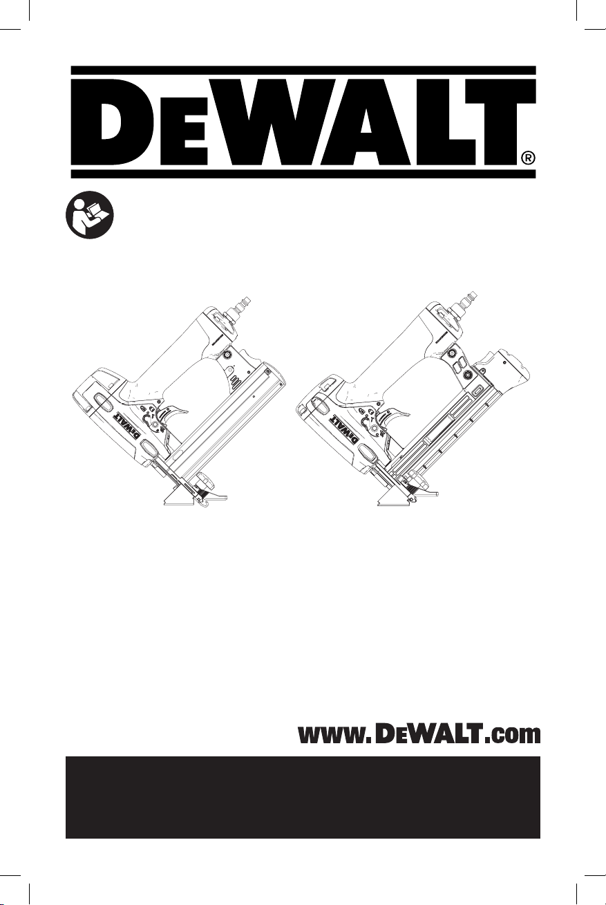
LOADING THE DWEHF1838K & DWLHF2025K
1. Depress magazine release button and pull
back magazine.
2. Open magazine fully and turn tool sideways
with discharge area pointed away from
yourself and others. Load staples in
channel.
3. Push magazine forward until latch is
engaged.
-7-
Page 8
ADJUSTMENT INSTRUCTIONS
DeWALT
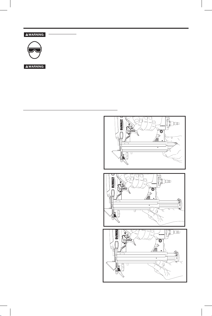
KNOB
FLOOR
VAPOR BARRIER
SUBFLOOR
FOOT
NOSE
FRONT GUIDE
TONGUE OF FLOORING
TO ADJUST THE TOOL TO THE FLOORING
1. Loosen both Knobs until the Foot and Front Guide move freely.
2. Engage the Nose with the Tongue of Flooring.
3. Push the Front Guide to the subfloor and the Foot to the flooring.
4. Tighten both Knobs.
Refer to the flooring manufactures installation instructions for proper fastener and
fastening technique.
IMPORTANT: Test the tool on a scrap piece of flooring to ensure proper staple placement and
compatibility.
improperly or not in accordance with the flooring manufacturer’s installation instructions.
cannot assume responsibility for product performance if the tool is used
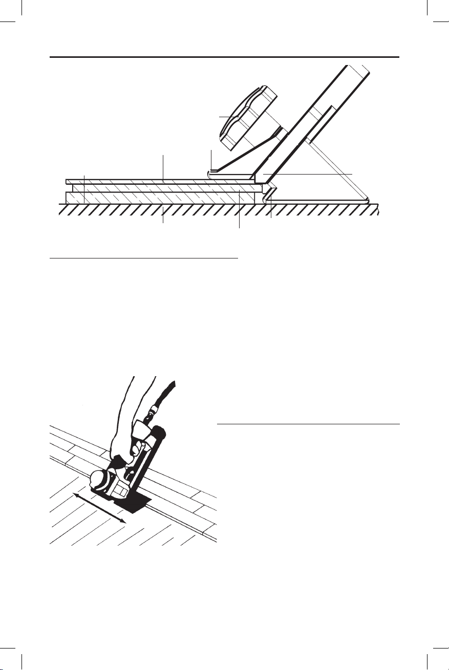
With tool properly located on tongue of flooring,
slide the tool along the tongue without lifting the
tool off the floor while fastening as shown above
and to the left.
AIR PRESSURE:
Air pressure must be adjusted to properly
countersink the staples. Air pressure should be
set using a scrap piece of flooring to adjust the air
pressure for correct countersinking.
(See following page)
-8-
Page 9
BEFORE OPERATING THIS TOOL, STUDY THESE INSTRUCTIONS AND OPERATION
DeWALT
AND MAINTENANCE MANUAL FOR YOUR TOOL TO UNDERSTAND THE SAFETY
WARNINGS AND INSTRUCTIONS. IF YOU HAVE ANY QUESTIONS, CONTACT YOUR
REPRESENTATIVE OR DISTRIBUTOR. SAVE THESE INSTRUCTIONS FOR FUTURE
REFERENCE.
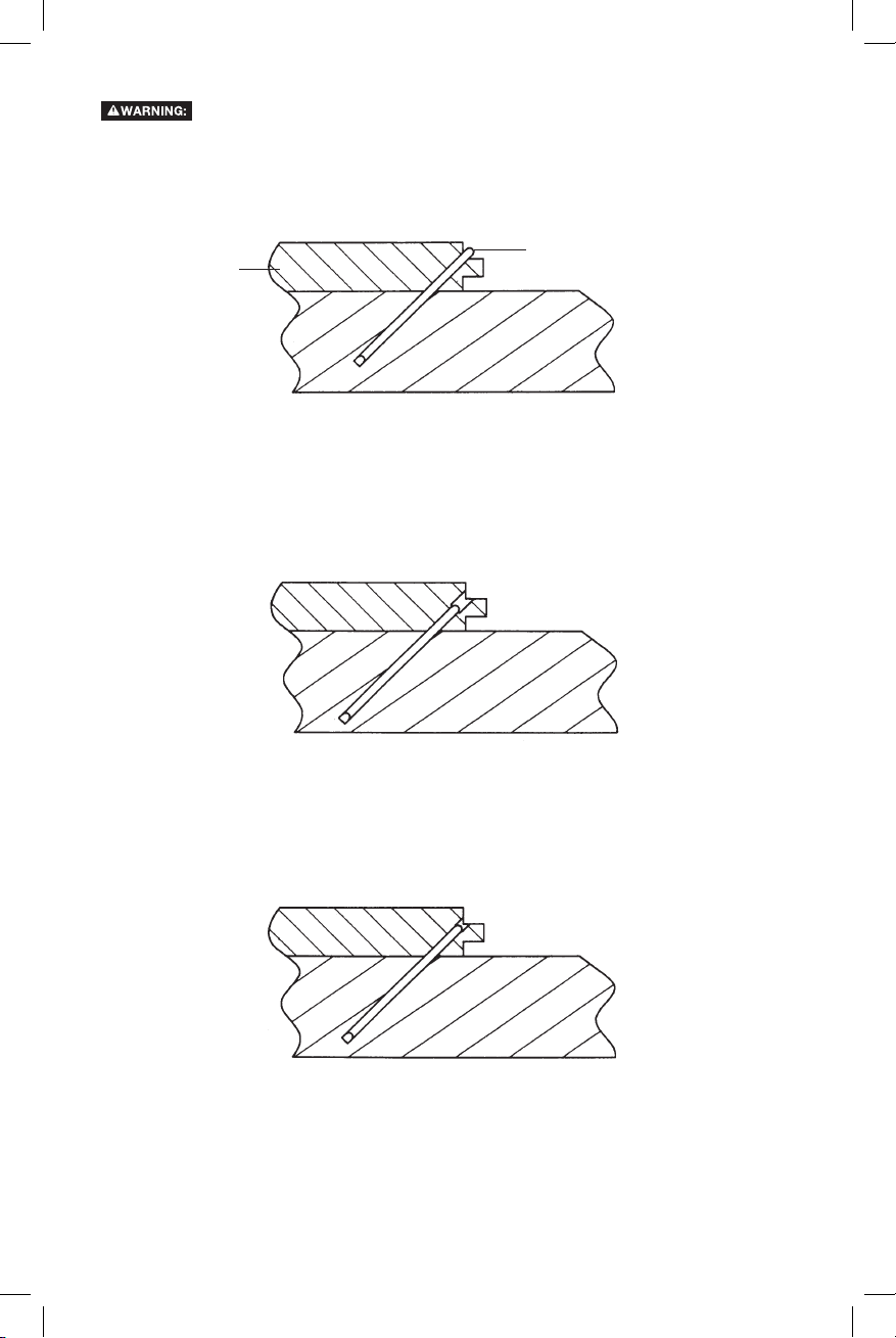
FLOOR
STAPLE
• Air pressure too low.
• Staple crown above tongue.
• Increase air pressure.
• Air pressure too high.
• Staple buried.
• Lower air pressure.
• Correct air pressure.
• Staple just below surface.
-9-
Page 10

TOOL OPERATION
DeWALT
DeWALT
DeWALT
EYE PROTECTION which conforms to ANSI specifications and provides protection against
flying particles both from the FRONT and SIDE should ALWAYS be worn by the operator
and others in the work area when connecting to air supply, loading, operating or servicing
this tool. Eye protection is required to guard against flying fasteners and debris, which
could cause severe eye injury.
The employer and/or user must ensure that proper eye protection is worn. Eye protection
equipment must conform to the requirements of the American National Standards
Institute, ANSI Z87.1 and provide both frontal and side protection. NOTE: Non-side shielded
spectacles and face shields alone do not provide adequate protection.
BEFORE HANDLING OR OPERATING THIS TOOL:
I. READ AND UNDERSTAND THE WARNINGS CONTAINED IN THIS MANUAL.
II. REFER TO “TOOL SPECIFICATIONS” IN THIS MANUAL TO IDENTIFY THE OPERATING SYSTEM
ON YOUR TOOL.
OPERATION
The operator must not hold the trigger pulled on contact trip tools except during fastening
operation, as serious injury could result if the trip accidentally contacted someone or
something, causing the tool to cycle.
Keep hands and body away from the discharge area of the tool. A contact trip tool may
bounce from the recoil of driving a fastener and an unwanted second fastener may be
driven, possibly causing injury.
SEQUENTIAL TRIP OPERATION:
In SEQUENTIAL TRIP MODE the contact trip operates in conjunction with the trigger to drive a fastener.
To operate a sequential trip tool, first position the contact trip on the work surface WITHOUT PULLING
THE TRIGGER. Depress the contact trip and then pull the trigger to drive a fastener. As long as the contact
trip is contacting the work and is held depressed, the tool will drive a fastener each time the trigger is
depressed. If the contact trip is allowed to leave the work surface, the sequence described above must be
repeated to drive another fastener.
If the tool has been dropped or you suspect tool damage perform tool operation check as
defined in the tool operation check section.
IN ADDITION TO THE OTHER WARNINGS CONTAINED
IN THIS MANUAL OBSERVE THE FOLLOWING FOR
SAFEOPERATION
• Use the
• Never use this tool in a manner that could cause a fastener to be directed toward the user
or others in the work area.
• Do not use the tool as a hammer.
• Always carry the tool by the handle. Never carry the tool by the air hose.
• Do not alter or modify this tool from the original design or function without approval from
• Always be aware that misuse and improper handling of this tool can cause injury to
yourself and others.
• Never clamp or tape the trigger or contact trip in an actuated position.
• Never leave a tool unattended with the air hose attached.
• Do not operate this tool if it does not contain a legible WARNING LABEL.
• Do not continue to use a tool that leaks air or does not function properly. Notify your nearest
pneumatic tool only for the purpose for which it was designed.
representative if your tool continues to experience functional problems.
-10-
.
Page 11

TOOL OPERATION CHECK
DeWALT
Remove all fasteners from tool before performing tool operation check.
If the tool is dropped or you suspect tool damage perform tool operation check.
A. Press the contact trip against the work surface, without touching the trigger.
THE TOOL MUST NOT CYCLE.
B. Hold the tool off the work surface and pull the trigger.
THE TOOL MUST NOT CYCLE.
Release the trigger. The trigger must return to the trigger stop on the frame.
C. Pull the trigger and press the contact trip against the work surface.
THE TOOL MUST NOT CYCLE.
D. With finger off the trigger, press the contact trip against the work surface. Pull the trigger.
THE TOOL MUST CYCLE.
SEQUENTIAL TRIP OPERATION:
MAINTAINING THE PNEUMATIC TOOL
When working on air tools, note the warnings in this manual and use extra care evaluating
problem tools.
If the tool has been dropped or you suspect tool damage perform tool operation check as
defined in the tool operation check section.
Pusher spring (constant force spring). Caution must be used when working with the
spring assembly. The spring is wrapped around, but not attached to, a roller. If the
spring is extended beyond its length, the end will come off the roller and the spring will
roll up with a snap, with a chance of pinching your hand. Also the edges of the spring
are very thin and could cut. Care must also be taken to insure no permanent kinks are
put in the spring as this will reduce the springs force.
REPLACEMENT PARTS
Use only genuine
ASSEMBLY PROCEDURE FOR SEALS
When repairing a tool, make sure the internal parts are clean and lubricated. Use Parker “O”-LUBE, Magnalube,
or equivalent on all “O”-rings. Coat each “O”-ring with lubricant before assembling.
replacement parts. Do not use modified parts.
AIR SUPPLY-PRESSURE AND VOLUME
Air volume is as important as air pressure. The air volume supplied to the tool may be inadequate because of
undersize fittings and hoses, or from the effects of dirt and water in the system. Restricted air flow will prevent the
tool from receiving an adequate volume of air, even though the pressure reading is high. The results will be slow
operation, misfeeds or reduced driving power. Before evaluating tool problems for these symptoms, trace the air
supply from the tool to the supply source for restrictive connectors, low points containing water and anything else
that would prevent full volume flow of air to the tool.
-11-
Page 12

TROUBLESHOOTING
DeWALT
PROBLEM CAUSE CORRECTION
Trigger valve housing leaks air O-ring cut or cracked ....................Replace O-ring
Trigger valve stem leaks air O-ring/seals cut or cracked ..............Replace trigger valve assembly
Frame/nose leaks air O-ring or gasket is cut or cracked. . . . . . . . . Replace O-ring or gasket
Bumper cracked/worn ...................Replace bumper
Frame/cap leaks air Damaged gasket or seal ................. Replace gasket or seal
Cracked/worn head valve ...............Replace head valve
Loose cap screws ......................Tighten and recheck
Failure to cycle Air supply restriction ....................Check air supply equipment
Worn head valve .......................Replace head valve
Broken cylinder cap spring ...............Replace cylinder cap spring
Head valve stuck in cap .................Disassemble / Check / Lubricate
Lack of power; slow to cycle Broken cylinder cap spring ...............Replace cap spring
Rings/seals cut or cracked ...............Replace rings/seals
Exhaust blocked ........................Check bumper, head valve spring
Trigger assembly worn/leaks .............Replace trigger assembly
Dirt/tar build up on driver ................ Disassemble nose/driver to clean
Cylinder sleeve not seated correctly
on bottom bumper ......................Disassemble to correct
Air pressure too low .....................Check air supply equipment
Skipping fasteners;
intermittent feed Worn bumper ...........................Replace bumper
Tar/dirt in driver channel .................Disassemble and clean nose and driver
Air restriction/inadequate air flow through
quick disconnect socket and plug .........Replace quick disconnect fittings
Worn piston ring ........................Replace ring, check driver
Damaged pusher spring .................Replace spring
Low air pressure ........................Check air supply system to tool
Loose magazine nose screws ............Tighten all screws
Fasteners too short for tool. . . . . . . . . . . . . . . Use only recommended fasteners
Bent fasteners ..........................Discontinue using these fasteners
Wrong size fasteners ....................Use only recommended fasteners
Leaking head cap gasket ................Tighten screws/replace gasket
Trigger valve O-ring cut/worn ............Replace O-ring
Broken/chipped driver ...................Replace driver (check piston ring)
Dry/dirty magazine ......................Clean/lubricate use
Worn magazine .........................Replace magazine
Fasteners jam in tool Driver channel worn ....................Replace nose/check door
Wrong size fasteners ....................Use only recommended fasteners
Bent fasteners ..........................Discontinue using these fasteners
Loose magazine/nose screws ............ Tighten all screws
Broken/chipped driver ...................Replace driver
Air Tool Lubricant
-12-
Page 13

MAINTENANCE CHECKLIST
Maintenance Benefit Procedure Service Interval
Inspect trigger performance Ensure trigger system is in
proper working order
Refer to Tool Operation Check
section in this manual
Daily
Drain condensation from air
compressor tanks and air filters
(if present)
Clean magazine assembly Prevents accumlation of debris
Clean nose assembly Prevents accumlation of debris
Ensure all fasteners remain tight Prevent loose parts Tighten all fasteners with
Replace air fitting Maintains proper air flow to
Replace piston/driver assembly Maintains consistent drive
Replace O-rings Maintains engine for peak
Replace bumper Maintains engine for peak
Replace headvalve Maintains engine for peak
Replace engine cylinder Maintains engine for peak
Prevents accumlation of
moisture that can impede tool
performace
that could cause a jam
that could cause a jam
engine for peak performance
quality
performance
performance
performance
performance
Open drain cock on tanks and air
filters and drain all condensate
Blow clean with compressed air Daily
Blow clean with compressed air Daily
appropriately sized hex wrench
Remove worn air fitting and
replace with new fitting
Refer to replacement part kit
instructions
Refer to replacement part kit
instructions
Refer to replacement part kit
instructions
Refer to replacement part kit
instructions
Refer to replacement part kit
instructions
Daily
Weekly
50,000 Fasteners
150,000 Fasteners
250,000 Fasteners
250,000 Fasteners
250,000 Fasteners
500,000 Fasteners
-13-
Page 14

OTHER
DeWALT
DeWALT
FLOORING PRODUCTS
DWMIIIFS
15.5 GAUGE
FLOORING STAPLER
DWMFN-201
16 GAUGE MANUAL
FLOORING NAILER
16 GAUGE FLOORING NAILER
DWMIIIFN
DWFP12569
2-IN-1 15.5 GAUGE FLOORING
STAPLER AND 16 GAUGE
CLEAT NAILER
For more information log on to:
www.
.com
-14-
Page 15

INTRODUCCIÓN
DeWALT
DeWALT
DeWALT
DeWALT
DeWALT
DeWALT
DeWALT
DeWALT
DeWALT
DeWALT
DeWALT
Los modelos DeWALT DWEHF1838K y DWLHF2025K son herramientas construidas a precisión, diseñadas
para funcionar a alta velocidad y con alto volumen. Estas herramientas entregan un servicio eficiente y fiable
cuando se usan correctamente y con cuidado. Al igual que con toda herramienta automática de calidad, deben
seguirse las instrucciones del fabricante para obtener el óptimo rendimiento. Estudie este manual antes de
operar la herramienta y tome nota de las advertencias y precauciones de seguridad. Deben leerse en detalle
las instrucciones sobre la instalación, operación y mantenimiento, y deben conservarse los manuales para
referencia. NOTA: Pueden necesitarse medidas adicionales de seguridad según la aplicación particular de
la herramienta. Comuníquese con su representante o distribuidor de DeWALT por cualquier pregunta sobre
la herramienta y su uso. DEWALT Industrial Tool Co., 701 East Joppa Road, Towson, MD 21286, llamada
1-800-4-DeWALT (1-800-433-9258) o visite nuestro sitio web www.dewalt.com.
ÍNDICE
Instrucciones de seguridad .......................................16
Componentes de las herramientas .................................17
Especificaciones de la herramienta/Sujetador .........................18
Suministro de aire y conexiones ...................................19
Cargar la herramienta ...........................................20
Instrucciones de ajuste ..........................................21
Operación de la herramienta . . . . . . . . . . . . . . . . . . . . . . . . . . . . . . . . . . . . . . 23
Revisión funcional de la herramienta ................................24
Mantenimiento de la herramienta neumática .........................24
Solución de problemas ..........................................25
Lista de verificación de mantenimiento ..............................26
Otros productos
para pisos ...............................27
Las herramientas
rendimiento al utilizarse con fijaciones de precisión
no puede asumir responsabilidad alguna por el rendimiento del producto si se utilizan
nuestras herramientas con fijaciones o accesorios que no reúnen los requisitos específicos establecidos
para los clavos, grapas y accesorios genuinos de
a partir de la fecha de compra. Esta garantía no cubre la falla de piezas debido al desgaste normal o abuso de
la herramienta. Para obtener más información sobre la cobertura de la garantía y la información de reparación
de la garantía, visite www.dewalt.com o llame al 1 800 433-9258 (1 800 4a accesorios o daños causados en caso de que terceros realicen o intenten realizar reparaciones. Esta garantía
le proporciona derechos legales específicos y usted puede tener otros derechos que varían en ciertos estados
o provincias.
Además de esta garantía, las herramientas
cualquier momento durante el primer año después de la compra. Los elementos que sufren desgaste de la
clavadora, como juntas tóricas y hojas de transmisión, no están cubiertos.
reparará, sin cargo alguno, los defectos en materiales o por mano de obra defectuosa por siete años
mantendrá la herramienta y reemplazará las piezas desgastadas por el uso normal sin costo y en
se han diseñado para brindar una satisfacción excelente al cliente y lograr máximo
GARANTÍA LIMITADA POR SIETE AÑOS
SERVICIO GRATUITO DE 1 AÑO
están cubiertas por nuestro:
diseñadas con las mismas normas estrictas.
.
). Esta garantía no se aplica
GARANTÍA DE REEMBOLSO DE 90 DÍAS
Si usted no está completamente satisfecho con el rendimiento de su herramienta eléctrica, láser o clavadora
por algún motivo, puede devolverlos dentro de los 90 días posteriores a la fecha de compra con un
recibo para obtener un reembolso completo, sin ninguna pregunta.
AMÉRICA LATINA: Esta garantía no es de aplicación a productos vendidos en América Latina. Para productos
vendidos en América Latina, consulte la información de la garantía específica del país incluida en el embalaje,
contacte a la compañía local o consulte el sitio web para obtener información acerca de la garantía.
REEMPLAZO GRATUITO DE LA ETIQUETA DE ADVERTENCIA: Si sus etiquetas de advertencia son ilegibles
o se extravían, llame al 1 800 433-9258 (1 800 4-
) para obtener un reemplazo gratuito.
NOTA:
-15-
Page 16

INSTRUCCIONES DE SEGURIDAD
ATENCIÓN:
El operador y otros en el área SIEMPRE deben llevar PROTECCIÓN OCULAR en conformidad con las
especificaciones ANSI y que proteja contra partículas que vuelen por DELANTE y por el LADO, cuando
se haga la conexión al suministro de aire, así como al cargar, operar o dar servicio a esta herramienta.
Se exige protegerse la vista para resguardarse contra fijaciones o residuos que vuelen, lo cual puede
causar lesiones graves a los ojos.
El empleador y/o el usuario deben asegurar que se protejan debidamente los ojos. El equipo de
protección ocular debe estar en conformidad con los requisitos del Instituto Nacional Americano de
Normas (American National Standards Institute), ANSI Z87.1 y proteger por delante y por el costado.
NOTA: Los anteojos o caretas sin protección lateral por sí solos no dan una protección adecuada.
En algunos ambientes se necesitará protección adicional de seguridad. Por ejemplo, el
el usuario deben comprobar que se cuente con la protección necesaria del oído y que el operador y los
demás presentes en el área la usen. Algunos ambientes exigirán el uso de casco protector. Cuando sea
necesario, el empleador y el usuario deben verificar que se proteja la cabeza en conformidad con la
norma ANSI Z89.1.
área de trabajo puede exponer a un nivel de ruido que lesione el oído. El empleador y
SUMINISTRO DE AIRE Y CONEXIONES
No use oxígeno, gases combustibles ni gases envasados en cilindros para operar esta herramienta
porque puede explotar, causando posibles lesiones.
No use fuentes de suministro que tengan el potencial de superar 14 kg/cm2 (200 psig) dado que la
herramienta puede explotar, causando posibles lesiones.
El conector de la herramienta no debe contener presión cuando se desconecte el suministro de
aire. Si se usa el conector indebido, la herramienta puede mantenerse cargada con aire después de
desconectarla y podría impulsar una fijación incluso después de desconectar la línea de aire, causando
posibles lesiones.
No accione el gatillo ni oprima el brazo de contacto mientras esté conectado al suministro de aire
porque la herramienta puede hacer un ciclo, causando posibles lesiones.
Siempre desconecte el suministro de aire: 1.) Antes de hacer ajustes; 2.) Al dar servicio a la
herramienta; 3.) Al despejar un atasco; 4.) Cuando no está en uso la herramienta; 5.) Al avanzar a
otra área de trabajo, porque puede activarse accidentalmente, causando posibles lesiones.
CARGA DE LA HERRAMIENTA
Al cargar la herramienta: 1.) Nunca ponga la mano ni ninguna otra parte del cuerpo en el área aplicadora
de descarga de la herramienta; 2.) Nunca apunte la herramienta a ninguna persona; 3.) No accione el
gatillo ni pulse el disparador porque puede activarse accidentalmente, causando posibles lesiones.
FUNCIONAMIENTO
Siempre maneje la herramienta con cuidado: 1.) Nunca participe en juegos rudos; 2.) Nunca accione
el gatillo a menos que la punta esté dirigida hacia el trabajo; 3.) Mantenga a los demás a una distancia
segura de la herramienta mientras esté en funcionamiento porque puede activarse accidentalmente,
causando posibles lesiones.
El operador no debe sostener el gatillo accionado en las herramientas con brazos de contacto salvo
durante la aplicación de fijaciones ya que pueden ocurrir lesiones graves si el disparo tomara contacto
accidentalmente con algo o alguien, ocasionando que la herramienta haga un ciclo.
Mantenga las manos y el cuerpo alejados del área de descarga de la herramienta. Una herramienta con
brazo de contacto puede rebotar al aplicar una fijación haciendo salir otra, causando posibles lesiones.
Revise frecuentemente el funcionamiento del mecanismo del brazo de contacto. No use la
herramienta si el brazo no funciona correctamente ya que puede impulsarse accidentalmente una
fijación. No interfiera con el funcionamiento adecuado del mecanismo del brazo de contacto.
No aplique clavos o grapas encima de otras ni con la herramienta en un ángulo demasiado agudo pues
esto puede ocasionar su deflexión, pudiendo causar lesiones.
No aplique grapas cerca del borde de la pieza con la cual esté trabajando pues la madera puede
dividirse, permitiendo la deflexión del clavo o grapa, causando posibles lesiones.
Esta clavadora produce CHISPAS durante la operación. NUNCA use la clavadora cerca de sustancias,
gases ni vapores inflamables, incluidos lacas, pintura, bencina, gasolina, adhesivos, mástique,
pegamentos ni ningún otro material que sea inflamable, combustible o explosivo -- o vapores,
emanaciones o subproductos que puedan serlo. Si se usa la clavadora en cualquier ambiente de
este tipo podría causar una EXPLOSIÓN produciendo lesiones físicas o fatales para el usuario y las
personas en la cercanía.
-16-
Page 17

Tapa del armazón
Protector del
armazón
Armazón
MANTENIMIENTO DE LA HERRAMIENTA
Al trabajar con herramientas neumáticas, observe las advertencias de este manual y tenga sumo
cuidado al evaluar herramientas con problemas.
Si la herramienta se ha caído o si sospecha daño a la herramienta, realice una comprobación
de funcionamiento de la herramienta tal como se define en la sección de comprobación de
funcionamiento de la herramienta.
COMPONENTES DE LA HERRAMIENTA
Conector de
aire
Escape posterior
Agarre cómodo sobremoldeado
Bloqueo
del gatillo
Gatillo
Perillas de precisión ajustables
Depósito Botón
de liberación
Indicador de recarga
Enganche de le
lengüeta Easy-Sight
-17-
Page 18

ESPECIFICACIONES DE LA HERRAMIENTA
DeWALT
DeWALT
DeWALT
DeWALT
DeWALT
Todas las dimensiones están en pulgadas a menos que se especifique lo contrario.
DWEHF1838K DWLHF2025K
Descripción Engrapadora para duela calibre18 Engrapadora para duela calibre 20
Tipo de motor Sin aceite Sin aceite
Rango de presión operativa 4,9 - 8,4 kg/cm2 (70 a 120 psig) 4,9 - 8,4 kg/cm2 (70 a 120 psig)
Máxima presión operativa 8,4 kg/cm2 (120 psig) 8,4 kg/cm2 (120 psig)
Tipo de fijación Serie DNS181XX-2 DWCS20100
Calibre de la fijación Calibre 18 Calibre 20
Gama de la fijación 25 mm - 38 mm (1" a 1-1/2") 25 mm (1")
Capacidad del depósito 100 125
Largo 235 mm (9-1/4") 235 mm (9-1/4")
Ancho 70 mm (2-3/4") 70 mm (2-3/4")
Altura 251 mm (9-7/8") 216 mm (8,5")
Peso
Presión operativa
4 ,9 a 8,4 kg/cm2 (70 a 120 psig). Seleccione la presión de operación dentro de este rango para el mejor
desempeño del sujetador.
NO SUPERE ESTA PRESIÓN OPERATIVA RECOMENDADA.
Consumo de aire
La DWEHF1838K requiere 55 litros por minuto o L/min (1.94 pies cúbicos por minuto o cfm) de aire libre a
5.6kg/cm2 (80 PSI) para operar a una velocidad de 60 sujetadores por minuto. La DWLHF2025K requiere 54
litros por minuto o L/min (1.90 pies cúbicos por minuto o cfm) de aire libre a 5.6 kg/cm2 (80 PSI) para operar a
una velocidad de 60 sujetadores por minuto. Para determinar el tamaño adecuado del compresor de aire, tome
la velocidad real en la cual se utilizará la herramienta y compare los L/min (cfm) requeridos con la entrega de
aire libre (FAD) del compresor (L/min o cfm) a 5.6 kg/cm2 (80 PSI).
Por ejemplo, si usted usa en promedio 30 sujetadores por minuto, necesita el 50 % del volumen de aire (L/min
o cfm) que se requiere para operar la herramienta a una velocidad de 60 sujetadores por minuto. En este caso,
para un rendimiento óptimo, asegúrese de que su compresor de aire pueda entregar un mínimo de 27.5 L/min
(0.97 cfm) a 5.6 kg/cm2 (80 PSI).
1,57 kg (3,5 lb) 1,32 kg (2,9 lb)
ESPECIFICACIONES DE FIJACIONES
Modelo de
herramienta
DWEHF1838K
DWLHF2025K
* Si desea obtener más detalles, visite www.
NOTA:
Las herramientas
al utilizarse con fijaciones de precisión
responsabilidad alguna por el rendimiento del producto si se utilizan nuestras herramientas con fijaciones
o accesorios que no reúnen los requisitos específicos establecidos para fijaciones y accesorios genuinos
de
.
Tipo de
fijación
Grapas
Grapas DWCS20100 4,7 mm (3/16") 20 25 mm (1")
se han diseñado para brindar una satisfacción excelente al cliente y lograr máximo rendimiento
SKU de
la fijación
DNS18100-2 (6,3 mm) 1/4" 18 25 mm (1")
DNS18125-2 (6,3 mm) 1/4" 18 31,75 mm (1-1/4")
DNS18150-2 (6,3 mm) 1/4" 18 38 mm (1-1/2")
diseñadas con las mismas normas estrictas.
Ancho
de corona
.com.
Calibre Largo
no puede asumir
-18-
Page 19

SUMINISTRO DE AIRE Y CONEXIONES
No use oxígeno, gases combustibles ni gases envasados en cilindros para operar esta herramienta
porque puede explotar, causando posibles lesiones.
CONECTORES
Instale un enchufe macho en la herramienta que está fluyendo libremente y que liberará presión de aire de la herramienta
al desconectarse de la fuente de alimentación.
MANGUERAS
Las mangueras de aire deben tener una presión nominal de trabajo mínima de 10.6 kg/cm2 (150 psig) de capacidad nominal
de presión de trabajo o un 150 por ciento de la presión máxima que podría producirse en el sistema de aire. La manguera
de suministro debe contar con un conector de “desconexión rápida” del enchufe macho en la herramienta.
FUENTE DE SUMINISTRO
Use solamente aire comprimido regulado limpio como fuente de energía para esta herramienta. NUNCA USE OXÍGENO,
GASES COMBUSTIBLES O GASES ENVASADOS EN CILINDROS COMO FUENTE DE ENERGÍA PARA ESTA
HERRAMIENTA, PUES LA HERRAMIENTA PUEDE EXPLOTAR.
REGULADOR
Se necesita un regulador de presión con una presión operativa de 0 - 8.8 kg/cm2 (0 a 125 psig) para controlar la presión
operativa con el fin de que la herramienta funcione en forma segura. No conecte esta herramienta a la presión de aire
que potencialmente pueda superar 14 kg/cm2 (200 psig) porque la herramienta puede fracturarse o explotar, causando
posibles lesiones.
PRESIÓN OPERATIVA
No supere la presión operativa máxima recomendada porque aumentará considerablemente el desgaste de la
herramienta. El suministro de aire debe ser capaz de mantener la presión operativa de la herramienta. Las caídas de
presión en el suministro de aire pueden reducir la energía impulsora de la herramienta. Consulte las “OPERACIÓN DE LA
HERRAMIENTA” para establecer la presión operativa correcta de la herramienta.
Enchufe de
desconexión rápida
Enchufe de conexión
rápida
-19-
Page 20

CARGA DE LA DWEHF1838K Y LA DWLHF2025K
El operador y otros en el área SIEMPRE deben llevar PROTECCIÓN OCULAR en conformidad
con las especificaciones ANSI y que proteja contra partículas que vuelen por DELANTE y
por el LADO, cuando se haga la conexión al suministro de aire, así como al cargar, operar
o dar servicio a esta herramienta. Se exige protegerse la vista para resguardarse contra
fijaciones o residuos que vuelen, lo cual puede causar lesiones graves a los ojos.
El empleador o el usuario deben asegurar que se protejan debidamente los ojos. El equipo
de protección ocular debe estar en conformidad con los requisitos del Instituto Nacional
Americano de Normas (American National Standards Institute), ANSI Z87.1 y proteger por
delante y por el costado. NOTA: Los anteojos o caretas sin protección lateral por sí solos
no dan una protección adecuada.
PARA PREVENIR LESIONES ACCIDENTALES:
• Nunca coloque la mano ni ninguna parte del cuerpo en el área de descarga de clavos de
la herramienta mientras esté conectado el suministro de aire.
• Nunca apunte la herramienta hacia una persona.
• Nunca participe en juegos rudos.
• Nunca accione el gatillo a menos que la punta esté dirigida hacia el trabajo.
• Siempre maneje la herramienta con cuidado.
• No accione el gatillo ni oprima el mecanismo de disparo mientras carga la herramienta.
CARGA DE LA DWEHF1838K & DWLHF2025K
1. Oprima el botón de liberación del depósito y
mueva hacia atrás el depósito.
2. Abra el depósito totalmente y gire la herramienta de
lado con el área de descarga apuntando lejos de
usted y de otras personas. Cargue las grapas en el
canal.
3. Empuje el depósito hacia delante hasta que se
enganche el pestillo.
-20-
Page 21

INSTRUCCIONES DE AJUSTE
DeWALT
BOTÓN
PISO
BARRERA FRONTAL
SUBPISO
PIE
LENGÜETA DE
REVESTIMIENTO DEL PISO
GUÍA FRONTAL
NARIZ
PARA AJUSTAR LA HERRAMIENTA AL REVESTIMIENTO DE PISO
1. Afloje ambos botones hasta que la guía frontal y de pie se muevan libremente.
2. Encaje la nariz en la lengüeta del revestimiento de piso.
3. Empuje la guía frontal contra el subpiso y el pie contra el revestimiento del piso.
4. Apriete ambos botones.
Consulte las instrucciones de instalación del fabricante del piso para utilizar una técnica
de remaches y sujeción apropiada.
IMPORTANTE: Faites un essai de l’outil sur un débris de plancher pour assurer le
positionnement adéquat de l’agrafe et la compatibilité.
de la performance du produit si l’outil n’est pas utilisé correctement ou s’il n’est pas utilisé
conformément aux instructions d’installation des fabricants de planchers.
Con la herramienta colocada apropiadamente en
la lengüeta del revestimiento de piso, deslice la
herramienta a lo largo de la lengüeta sin levantar
la herramienta del piso mientras clava, tal como
se muestra arriba y a la izquierda.
ne peut être responsable
PRESIÓN DE AIRE:
La pression d’air doit être réglée pour obtenir un
enfoncement adéquat des agrafes. La pression
d’air doit être réglée en utilisant un débris de
plancher jusqu’à l’obtention d’un enfoncement
adéquat.
(Vea la página siguiente)
-21-
Page 22

ANTES DE OPERAR ESTA HERRAMIENTA, ESTUDIE ESTAS INSTRUCCIONES Y
DeWALT
MANUAL DE OPERACIÓN Y MANTENIMIENTO PARA SU HERRAMIENTA PARA QUE
ENTIENDA LAS ADVERTENCIAS E INSTRUCCIONES DE SEGURIDAD. SI TIENE ALGUNA
PREGUNTA, DIRÍJASE A SU REPRESENTANTE O DISTRIBUIDOR DE
ESTAS INSTRUCCIONES PARA REFERENCIA EN EL FUTURO.
. GUARDE
PISO
• Presión de aire demasiado baja.
• Corona de la grapa está encima de la lengüeta.
• Aumentar la presión de aire.
• Presión de aire demasiado alta.
• Grapa enterrada.
• Bajar la presión de aire.
GRAPA
• Corregir la presión de aire.
• Grapa justamente debajo de la superficie.
-22-
Page 23

OPERACIÓN DE LA HERRAMIENTA
DeWALT
DeWALT
DeWALT
El operador y otros en el área SIEMPRE deben llevar PROTECCIÓN OCULAR en conformidad
con las especificaciones ANSI y que proteja contra partículas que vuelen por DELANTE y
por el LADO, cuando se haga la conexión al suministro de aire, así como al cargar, operar
o dar servicio a esta herramienta. Se exige protegerse la vista para resguardarse contra
fijaciones o residuos que vuelen, lo cual puede causar lesiones graves a los ojos.
El empleador o el usuario deben asegurar que se protejan debidamente los ojos. El equipo
de protección ocular debe estar en conformidad con los requisitos del Instituto Nacional
Americano de Normas (American National Standards Institute), ANSI Z87.1 y proteger por
delante y por el costado. NOTA: Los anteojos o caretas sin protección lateral por sí solos
no dan una protección adecuada.
ANTES DE MANIPULAR U OPERAR ESTA HERRAMIENTA:
I. LEA DETALLADAMENTE LAS ADVERTENCIAS CONTENIDAS EN ESTE MANUAL.
II. CONSULTE LAS “ESPECIFICACIONES DE LA HERRAMIENTA” EN ESTE MANUAL PARA IDENTIFICAR
EL SISTEMA OPERATIVO DE LA HERRAMIENTA.
OPERACIÓN
El operador no debe sostener el gatillo accionado en las herramientas con disparo de
contacto salvo durante la aplicación de fijaciones ya que pueden ocurrir lesiones graves
si el disparador tomara contacto accidentalmente con algo o alguien, ocasionando que la
herramienta haga un ciclo.
Mantenga las manos y el cuerpo alejados del área de descarga de la herramienta. Una
herramienta con disparo de contacto puede rebotar al aplicar una fijación haciendo salir
otra, causando posibles lesiones.
FUNCIONAMIENTO DEL DISPARO SECUENCIAL:
En el MODO DE DISPARO SECUENCIAL el disparo de contacto funciona en conjunto con el gatillo para impulsar
una fijación. Para usar una herramienta con disparo secuencial, primero coloque el disparo de contacto sobre
la superficie de trabajo SIN ACCIONAR ELGATILLO. Oprima el disparo de contacto y luego accione el gatillo
para aplicar una fijación. Siempre y cuando el disparo de contacto toque el trabajo y se mantenga oprimido, la
herramienta aplicará una fijación cada vez que se oprima el gatillo. Si se deja que el disparo de contacto se separe
de la superficie de trabajo, debe repetirse la secuencia descrita más arriba para colocar otra fijación.
Si la herramienta se ha caído o si sospecha daño a la herramienta, realice una comprobación
de funcionamiento de la herramienta tal como se define en la sección de comprobación de
funcionamiento de la herramienta.
ADEMÁS DE LAS OTRAS ADVERTENCIAS CONTENIDAS
EN ESTE MANUAL OBSERVE LO SIGUIENTE PARA LA
OPERACIÓN SEGURA
• Use la herramienta neumática
• Nunca use esta herramienta de tal modo que pueda causar la salida de una fijación hacia
el usuario u otros presentes en el área de trabajo.
• No use la herramienta como martillo.
• Siempre lleve la herramienta tomándola por la empuñadura. Nunca lleve la herramienta tomándola
por la manguera de aire.
• No altere ni modifique el diseño o función original de esta herramienta sin la aprobación de
• Siempre tenga presente que el uso indebido o la manipulación incorrecta de esta herramienta
puede causarle lesiones a usted y a los demás.
• Nunca use abrazaderas ni cinta para bloquear el gatillo o el disparo de contacto en
la posición activada.
• Nunca deje una herramienta sin supervisión con la manguera de aire conectada.
• No opere esta herramienta si no cuenta con una ETIQUETA DE ADVERTENCIA legible.
• Deje de usar la herramienta si tiene fugas de aire o no funciona bien. Notifique al representante
.
más cercano de
si la herramienta continúa experimentando problemas funcionales.
solamente para el fin que fue diseñada.
-23-
Page 24

REVISIÓN FUNCIONAL DE LA HERRAMIENTA
ATENCIÓN:
ATENCIÓN:
DeWALT
Retire todas las fijaciones de la herramienta antes de revisar cómo funciona.
Si la herramienta se ha caído o sospecha daño a la herramienta, realice una comprobación
de funcionamiento de la herramienta.
FUNCIONAMIENTO DEL DISPARO SECUENCIAL:
A. Presione el disparo de contacto contra la superficie de trabajo, sin tocar el gatillo.
NO DEBE HACER UN CICLO LA HERRAMIENTA.
B. Sostenga la herramienta sin tocar la superficie de trabajo y accione el gatillo.
NO DEBE HACER UN CICLO LA HERRAMIENTA.
Libere el gatillo. El gatillo debe regresar al tope del gatillo del armazón.
C. Accione el gatillo y presione el disparo de contacto contra la superficie de trabajo.
NO DEBE HACER UN CICLO LA HERRAMIENTA.
D. Con el dedo lejos del gatillo, presione el disparo de contacto contra la superficie de trabajo. Accione el gatillo.
DEBE HACER UN CICLO LA HERRAMIENTA.
MANTENIMIENTO DE LA HERRAMIENTA NEUMÁTICA
Al trabajar con herramientas neumáticas, observe las advertencias de este manual y tenga
sumo cuidado al evaluar herramientas con problemas.
Si la herramienta se ha caído o si sospecha daño a la herramienta, realice una comprobación
de funcionamiento de la herramienta tal como se define en la sección de comprobación de
funcionamiento de la herramienta..
Resorte de empuje (resorte de fuerza constante). Debe tenerse cuidado al trabajar con el
ensamblaje del resorte. El resorte va envuelto alrededor de un rodillo, no conectado al mismo.
Si el resorte se extiende más allá de su longitud, el extremo se saldrá del rodillo y el resorte se
enrollará con un chasquido, posiblemente pellizcándole la mano. Los bordes del resorte
también son muy finos y podrían cortar. Debe tenerse cuidado para asegurar que no se hagan
dobleces permanentes en el resorte porque esto reducirá la fuerza del mismo.
PIEZAS DE REPUESTO
Al cambiar piezas, solamente use repuestos genuinos
PROCEDIMIENTO DE ENSAMBLAJE PARA LOS SELLOS
Al reparar una herramienta, fíjese en que las piezas internas estén limpias y lubricadas. Use Parker “O”-LUBE, Magnalube
u otro lubricante equivalente en todas las juntas tóricas. Cubra cada junta tórica con lubricante antes del ensamblaje.
PRESIÓN Y VOLUMEN DEL SUMINISTRO DE AIRE
El volumen de aire es tan importante como la presión de aire. El volumen de aire suministrado a la herramienta puede ser
inadecuado debido a accesorios y mangueras de tamaño inferior o por los efectos de suciedad y agua en el sistema. El
flujo de aire restringido impedirá que la herramienta reciba un volumen de aire adecuado, aun cuando la lectura de presión
sea alta. Los resultados serán funcionamiento lento, fijaciones mal dirigidas o menor potencia de impulso. Antes de evaluar
los problemas de las herramientas según estos síntomas, inspeccione el suministro de aire desde la herramienta a la fuente
de suministro en busca de conectores restrictivos, puntos bajos que tengan agua y cualquier otra cosa que impida el flujo
del volumen completo de aire a la herramienta.
. No use piezas modificadas.
-24-
Page 25

SOLUCIÓN DE PROBLEMAS
DeWALT
PROBLEMA CAUSA CORRECCIÓN
El alojamiento de la válvula de
disparo tiene fuga de aire La junta tórica está cortada o agrietada ..........Cambie la junta tórica
El vástago de la válvula de disparo La junta tórica o los sellos están ................ Cambie el ensamblaje de la válvula de disparo
tiene fuga de aire cortados o agrietados
El armazón o la punta tiene fuga de aire La junta tórica o la empaquetadura está ......... Cambie la junta tórica o la empaquetadura
cortada o agrietada
El tope está agrietado o desgastado .............Cambie el tope
El armazón o la tapa tiene fuga de aire La empaquetadura o el sello está dañado ........Cambie la empaquetadura o el sello
La válvula cabezal está agrietada o desgastada ..Reemplace la válvula cabezal
Los tornillos de casquete están sueltos ..........Apriete y revíselos de nuevo
No hace ciclos El suministro de aire está restringido ............Revise el equipo de suministro de aire
La válvula cabezal está desgastada .............Reemplace la válvula cabezal
El resorte en la tapa del cilindro está roto ........Cambie el resorte de la tapa del cilindro
La válvula cabezal está pegada en la tapa ........Desarme / Revise/ Lubrique lo necesario
Falta alimentación; el ciclo es lento El resorte en la tapa del cilindro está roto ........Cambie el resorte de la tapa
Las juntas tóricas o los sellos están cortados ....Cambie las juntas tóricas o los sellos
o agrietados
Escape bloqueado ............................Revise el tope, el resorte de la válvula cabezal
El ensamblaje del gatillo está desgastado .......Cambie el ensamblaje del gatillo
o tiene fugas
Hay acumulación de suciedad o alquitrán .......Desarme la punta o el impulsor para limpiar
en el impulsor
El manguito del cilindro no está asentado
correctamente en el tope inferior ...............Desármelo para corregir esto
La presión de aire está demasiado baja ..........Revise el equipo de suministro de aire
Se saltan las fijaciones;
alimentación intermitente El tope está desgastado ........................Cambie el tope
Hay alquitrán o suciedad en el canal del impulsor ..Desarme y limpie la punta y el impulsor
Restricción de aire/flujo indebido de aire a través
del enchufe y la toma de desconexión rápida .....Cambie los accesorios de desconexión rápida
Está desgastado el anillo del pistón ..............Cambie el anillo, revise el impulsor
El resorte de empuje está dañado ...............Cambie el resorte
Hay baja presión de aire .......................Revise el sistema de suministro de aire a la herramienta
Los tornillos en la punta del depósito ............Apriete todos los tornillos
están sueltos
Las fijaciones son demasiado cortas para ....... Use solamente las fijaciones recomendadas
la herramienta
Hay fijaciones dobladas ........................Deje de usar estas fijaciones
Las fijaciones son del tamaño incorrecto .........Use solamente las fijaciones recomendadas
La empaquetadura de la tapa cabezal tiene fugas . Apriete los tornillos o cambie la empaquetadura
La junta tórica de la válvula de disparo está .....Cambie la junta tórica
cortada o desgastada
El impulsor está roto o picado ...................Cambie el impulsor (revise el anillo del pistón)
El depósito está seco o sucio ...................Limpie/lubrique con Lubricante para herramientas neumáticas
El depósito está desgastado ....................Cambie el depósito
Se atascan las fijaciones en la herramienta El canal del impulsor está desgastado ........... Cambie la punta, revise la puerta
Las fijaciones son del tamaño incorrecto .........Use solamente las fijaciones recomendadas
Hay fijaciones dobladas ........................Deje de usar estas fijaciones
Hay tornillos sueltos en el depósito o la punta ....Apriete todos los tornillos
El impulsor está roto o picado ...................Cambie el impulsor
-25-
Page 26

LISTA DE VERIFICACIÓN DE MANTENIMIENTO
Mantenimiento Beneficio Procedimiento Intervalo
de servicio
Inspeccione el funcionamiento del
gatillo o disparador
Drene la condensación de los
tanques y filtros de aire del
compresor de aire (si la hay)
Limpie el ensamblaje del depósito Previene la acumulación de
Limpie el ensamblaje de la punta Previene la acumulación de
Asegure que todas las fijaciones se
mantengan apretadas
Reemplace el conector de aire Mantiene el flujo de aire
Reemplace el ensamblaje de
pistón/impulsor
Cambie las juntas tóricas Mantiene el motor para lograr
Cambie el tope Mantiene el motor para lograr
Confirme que el sistema de
disparo funcione bien
Previene la acumulación de
humedad que p uede impedir
el buen rendimiento de la
herramienta
residuos que pudieran causar
atascos
residuos que pudieran causar
atascos
Prevenga las piezas sueltas Apriete todas las fijaciones con
correcto al motor para lograr
óptimo rendimiento
Mantiene la calidad constante
de impulso
óptimo rendimiento
óptimo rendimiento
Consulte la sección Revisión
funcional de la herramienta en
este manual
Abra la llave de drenaje en los
tanques y filtros de aire y drene
todo el condensado
Limpie soplando con aire
comprimido
Limpie soplando con aire
comprimido
la llave hexagonal del tamaño
apropiado
Remove worn air fitting and
replace with new fitting
Remítase a las instrucciones del
paquete de piezas de repuesto
Remítase a las instrucciones del
paquete de piezas de repuesto
Remítase a las instrucciones del
paquete de piezas de repuesto
Diariamente
Diariamente
Diariamente
Diariamente
Semanalmente
50,000 fijaciones
150,000 fijaciones
250,000 fijaciones
250,000 fijaciones
Cambie la válvula cabezal Mantiene el motor para lograr
Reemplace el cilindro del motor Mantiene el motor para lograr
óptimo rendimiento
óptimo rendimiento
Remítase a las instrucciones del
paquete de piezas de repuesto
Remítase a las instrucciones del
paquete de piezas de repuesto
-26-
250,000 fijaciones
500,000 fijaciones
Page 27

OTHER
DeWALT
DeWALT
FLOORING PRODUCTS
ENGRAPADORA PARA DUELA
DWMIIIFS
CALIBRE 15.5
DWMFN-201
CLAVADORA MANUAL PARA PISO
CALIBRE 16
DWMIIIFN
CLAVADORA PARA DUELA
CALIBRE 16
DWFP12569
ENGRAPADORA PARA PISOS
DE MADERA 2 EN 1 DE
CALIBRE 15.5 Y CLAVADORA
DE TACOS DE CALIBRE 16
Para obtener más información visite:
www.
.com
-27-
Page 28

INTRODUCTION
DeWALT
DeWALT
DeWALT
DeWALT
DeWALT
Les DWEHF1838K et DWLHF2025K de DeWALT sont des outils de précision, conçus pour la pose d’attaches
à haute vitesse et à haut volume. Ces outils vous donneront un rendement efficace et fiable lorsqu’utilisés
correctement et avec soin. Comme pour tout outil de précision, il est important de suivre les instructions du
fabricant pour obtenir la meilleure performance. Veuillez étudier ce manuel avant d’utiliser l’outil et comprendre
les avertissements et les mises en garde de sécurité. Les instructions ayant trait à l’installation, le fonctionnement
et l’entretien doivent être lues attentivement et les manuels doivent être conservés pour référence. REMARQUE :
Des mesures de sécurité additionnelles peuvent être requises en fonction de l’utilisation que vous faites de l’outil.
Communiquez avec votre représentant ou distributeur DeWALT pour toute question au sujet de cet outil et de son
utilisation. DeWALT Industrial Tool Co., 701 East Joppa Road, Towson, MD 21286, appelez 1-800-4-DeWALT
(1-800-433-9258) ou visitez notre website www.dewalt.com.
TABLE DES MATIÈRES
Consignes de sécurité ..........................................29
Composants de l'outil ...........................................30
Spécifications de l’outil/attaches ..................................31
Alimentation d’air et connexions ...................................32
Chargement de l’outil ...........................................33
Instructions de réglage ..........................................34
Fonctionnement de l’outil ........................................36
Vérification du fonctionnement de l’outil..............................37
Entretien de l’outil pneumatique ...................................37
Dépannage ...................................................38
Liste des vérifications d’entretien...................................39
Autres produits
pour planchers. ............................40
REMARQUE :
Les outils
atteindre une performance maximale lorsqu’utilisés avec les attaches
normes élevées.
avec des attaches ou des accessoires ne répondant pas strictement aux exigences établies pour les clous,
agrafes et accessoires d’origine
GARANTIE À VIE LIMITÉE DE SEPT (7) ANS
DeWALT réparera gratuitement tous les problèmes dus à des défauts de matériau ou de fabrication pendant
sept (7) ans à compter de la date d’achat. Cette garantie ne couvre pas des défaillances de pièce dues à une
usure normale ou à une mauvaise utilisation de l’outil. Pour en savoir plus sur la protection et les réparations sous
garantie, visiter le site Web www.dewalt.com ou composer le 1 800 433-9258 (1 800 4-DeWALT). Cette garantie
ne s’applique pas aux accessoires ni aux dommages causés par des réparations réalisées ou tentées par des
tiers. Cette garantie vous accorde des droits légaux précis et il est possible que vous ayez d’autres droits qui
varient d’un État ou d’une province à l’autre.
En plus de la garantie, les outils DeWALT sont couverts par notre:
ont été fabriqués afin d’offrir un degré de satisfaction de la clientèle très élevé et sont conçus pour
ne peut être tenu responsable de la performance du produit si les outils sont utilisés
.
de précision fabriquées avec les mêmes
SERVICE D’ENTRETIEN GRATUIT DE 1 AN
DeWALT entretiendra l’outil et remplacera les pièces usées par une utilisation normale et ce, gratuitement, à tout
moment pendant la première année à compter de la date d’achat. L’usure de pièces comme les joints toriques
ou les mécanismes de lames n’est pas couverte.
GARANTIE DE REMBOURSEMENT DE 90 JOURS
Si vous n’êtes pas entièrement satisfait des performances de votre outil électrique, laser ou de votre cloueuse
DeWALT pour quelque raison que ce soit, vous pouvez le renvoyer accompagné d’un reçu dans les 90 jours
suivant la date d’achat, et nous vous rembourserons entièrement – sans poser de questions.
AMÉRIQUE LATINE : Cette garantie ne s’applique pas aux produits vendus en Amérique latine. Pour ceux-ci,
veuillez consulter les informations relatives à la garantie spécifique présente dans l’emballage, appeler l’entreprise
locale ou consulter le site Web.
REMPLACEMENT GRATUIT DES ÉTIQUETTES D’AVERTISSEMENT: Si l’étiquette d’avertissement devient
illisible ou est manquante, composer le 1 800 433-9258 (1 800 4-DeWALT) pour un remplacement gratuit.
-28-
Page 29

CONSIGNES DE SÉCURITÉ
DES LUNETTES DE SÉCURITÉ se conformant aux normes ANSI et qui protègent des particules
projetées du côté FRONTAL ainsi que du côté LATÉRAL doivent TOUJOURS être portées par
l’opérateur et toute autre personnes se trouvant dans la zone de travail lors d’une connexion
à l’alimentation d’air, du chargement, de fonctionnement ou de l’entretien de cet outil. Une
telle protection est indispensable pour vous protéger contre les attaches et débris projetés,
susceptibles d’entraîner des blessures sérieuses.
L’employeur et/ou l’utilisateur doivent s’assurer que les lunettes de sécurité appropriées sont
portées. L’équipement de protection doit être conforme à la norme ANSI Z87.1 et fournir une
protection frontale et latérale. REMARQUE : Les lunettes sans protection latérale et les masques
faciaux ne fournissent pas la protection nécessaire.
environnements. Par exemple, la zone de travail peut comporter une exposition à un niveau de
bruit qui pourrait entraîner une diminution de l’acuité auditive. L’employeur et l’utilisateur doivent
s’assurer qu’une protection de l’ouïe est fournie et utilisée par l’opérateur et toute autre personne
dans la zone de travail. Certains environnements nécessiteront l’utilisation d’équipement de
protection de la tête. Lorsque requis, l’employeur et l’utilisateur doivent s’assurer qu’une
protection de la tête se conformant à la norme ANSI Z89.1 est utilisée.
Des articles de sécurité additionnels devront être portés dans certains
ALIMENTATION D’AIR ET CONNEXIONS
N’utilisez pas d’oxygène, de gaz combustibles ou de gaz en bouteille comme source d’alimentation
pour cet outil puisque cela peut causer l’explosion de l’outil et causer des blessures.
N’utilisez pas des sources d’alimentation pouvant excéder 200 lb/po2 (14 kg/cm2) car cela peut
causer l’éclatement de l’outil et causer des blessures.
Le connecteur de l’outil ne doit pas être sous pression lorsque l’outil est déconnecté. Si un raccord
incorrect est utilisé, l’outil peut demeurer sous pression après avoir été déconnecté et pourrait
donc décharger une attache même une fois la conduite d’air déconnectée et causer des blessures.
N’appuyez pas sur la gâchette et n’appuyez pas sur le bras de contact alors qu’il est connecté à
l’alimentation d’air, car l’outil pourrait alors être actionné et causer des blessures.
Veillez à toujours déconnecter l’alimentation d’air: 1.) Avant de procéder à des ajustements; 2.)
Au moment de réparer l’outil; 3.) Au moment de dégager un blocage; 4.) Lorsque l’outil n’est pas
utilisé; 5.) Au moment de se déplacer vers une zone de travail différente, puisque l’outil pourrait
être actionné accidentellement et causer des blessures.
CHARGEMENT DE L’OUTIL
Au moment de charger l’outil : 1.) Ne placez jamais la main ou toute autre partie du corps
dans la région de décharge d’attache de l’outil; 2.) Ne dirigez jamais l’outil vers quelqu’un; 3.)
N’appuyez pas sur la gâchette et n’appuyez pas sur le déclencheur puisqu’il pourrait être actionné
accidentellement et causer des blessures.
FONCTIONNEMENT
Veillez à toujours manipuler l’outil avec précaution : 1.) Ne vous chahutez jamais; 2.) N’appuyez
jamais sur la gâchette sans que le nez de pose soit dirigé vers la surface de travail; 3.) Maintenez
les autres à une distance sécuritaire alors que l’outil fonctionne puisqu’il pourrait être actionné
accidentellement et causer des blessures.
L’opérateur ne doit pas maintenir la gâchette enfoncée sur les outils à bras de contact sauf lors des
opérations d’attache puisque de graves blessures peuvent être causées si le déclencheur entrait
en contact avec quelqu’un ou quelque chose accidentellement, ce qui pourrait actionner l’outil.
Ne placez jamais la main ou le corps dans la zone de décharge de l’outil. Un outil à bras de contact
peut rebondir en raison du recul causé au moment de tirer une attache et une deuxième attache
pourrait être tirée inopinément et causer des blessures.
Vérifiez fréquemment le fonctionnement du mécanisme du bras de contact. N’utilisez pas l’outil
si le bras ne fonctionne pas correctement puisque cela peut causer le tir accidentel d’une attache.
Ne gênez pas le fonctionnement approprié du mécanisme de bras de contact.
Ne tirez pas d’attache sur une autre attache ou alors que l’outil est à un trop grand angle, car cela
peut causer une déflexion de l’attache et causer des blessures.
Ne tirez pas d’attache trop près du bord de la pièce de travail, car le bois pourrait fendre et
entraîner la déflexion de l’attache et causer des blessures.
La cloueuse produit des ÉTINCELLES lors du fonctionnement. N’utilisez JAMAIS la cloueuse près
de substances inflammables, de gaz ou de vapeurs, y compris la laque, la benzine, le diluant,
l’essence, les adhésifs, les mastics, les colles ou de tout autre matériau qui est – ou dont les
vapeurs, les émanations ou les sous-produits sont – inflammables, combustibles ou explosifs.
L’utilisation de la cloueuse dans un tel environnement pourrait mener à une EXPLOSION pouvant
causer des blessures ou le décès de l’utilisateur ou de personnes à proximité.
-29-
Page 30

ENTRETIEN DE L’OUTIL
Prenez note des avertissements de ce manuel lorsque vous travaillez avec des outils pneumatiques
et prenez toutes les précautions possibles lorsque vous évaluez les outils à problèmes.
Si l’outil a été échappé ou si vous soupçonnez qu’il est endommagé, effectuez une
vérification de fonctionnement de l’outil tel que défini dans la section de vérification de
fonctionnement de l’outil.
COMPOSANTS DE L’OUTIL
Poignée moulée confortable
Chapeau
de couple
Protecteur
de bâti
Bâti
Raccord
d’air à rotule
Échappement arrière
Magasin bouton
d’ouverture
Blocage de
gâchette
Gâchette
Indicateur de rechargement
Boutons de commandes
de précision
Languette d’insertion
facile à repérer
-30-
Page 31

DeWALT
DeWALT
DeWALT
DeWALT
DeWALT
SPÉCIFICATIONS DE L’OUTIL
Les mesures sont métriques suivies de mesures impériales entre parenthèses.
Description
Type de moteur
Plage de pression de fonctionnement
Pression de fonctionnement maximale
Type d’attache
Calibre d’attache
Plage d’attache
Capacité du magasin
Longueur
Largeur
Hauteur
Poids
Pression de fonctionnement
4,9 à 8,4 kg/cm2 (70 à 120 lb/po2). Sélectionnez la pression de fonctionnement selon cette étendue pour
obtenir le rendement optimal de l’agrafeuse.
NE DÉPASSEZ PAS LA PRESSION DE FONCTIONNEMENT RECOMMANDÉE.
Consommation d’air
Le modèle DWEHF1838K exige 1,94 pi3/min ou un rendement d’air libre de 55 L/min à une pression de
5,6 kg cm2 (80 lb/po2) pour fonctionner au taux de 60 attaches par minute. Le modèle DWLHF2025K exige
1,90pi3/min ou un rendement d’air libre de 54 L/min à une pression de 5,6 kg/cm2 (80 lb/po2) pour fonctionner
au taux de 60 attaches par minute. Pour déterminer le format compresseur approprié, utilisez le taux auquel l’outil
fonctionnera puis comparez le débit requis (L/min ou pi3/min) au rendement d’air libre (L/min ou pi3/min) à une
pression de 5,6 kg/cm2 (80 lb/po2).
Par exemple, si l’agrafeuse éjecte une moyenne de 30 attaches par minute, vous aurez besoin de 50 % du volume
d’air nécessaire (L/min ou pi3/min) pour pouvoir faire fonctionner l’outil à un taux de 60 attaches par minute.
Dans ce cas, assurez-vous que votre compresseur peut offrir un débit de 0,97 L/min (27,5 pi3/min) à 5,6 kg/cm
(80lbpo²) pour une performance optimale.
DWEHF1838K DWLHF2025K
Agrafeuse à plancher de calibre18 Agrafeuse à plancher de calibre20
Sans huile Sans huile
4,9 à 8,4 kg/cm² (70 à 120 lb/po2) 4,9 à 8,4 kg/cm2 (70 à 120 lb/po2)
8,4 kg/cm2 (120 lb/po2) 8,4 kg/cm2 (120 lb/po2)
Séries DNS181XX-2 DWCS20100
Calibre 18 Calibre 20
25 à 38 mm (1 à 1 1/2 po) 25 mm (1 po)
100 125
235 mm (9 1/4 po) 235 mm (9 1/4 po)
70 mm (2 3/4 po) 70 mm (2 3/4 po)
251 mm (9 7/8 po) 216 mm (8,5 po)
1,57 kg (3,5 lb) 1,32 kg (2,9 lb)
2
CARACTÉRISTIQUES DES ATTACHES
Modèle d’outil
DWEHF1838K
DWLHF2025K
Type
d’attache
Agrafes
Agrafes DWCS20100 4,7 mm (3/16 po.) 20 25 mm (1 po.)
* Visitez notre site au www.
REMARQUE :
Les outils
atteindre une performance maximale lorsqu’utilisés avec les attaches
normes élevées.
de fixation ou accessoires ne répondant pas strictement aux exigences établies pour les clous, attaches et
accessoires d’origine
ont été fabriqués afin d’offrir un degré de satisfaction de la clientèle supérieur et sont conçus pour
ne garantit pas les performances de vos outils s’ils sont utilisés avec des dispositifs
N° stock de
l’attache
Largeur de
couronne
Calibre Longueur
DNS18100-2 (6,3 mm) 1/4 po. 18 25 mm (1 po.)
DNS18125-2 (6,3 mm) 1/4 po. 18 31,75 mm (1-1/4 po.)
DNS18150-2 (6,3 mm) 1/4 po. 18 38 mm (1-1/2 po.)
.com pour obtenir plus d’information.
de précision fabriquées avec les mêmes
.
-31-
Page 32

ALIMENTATION D’AIR ET CONNEXIONS
N’utilisez pas d’oxygène, de gaz combustibles ou de gaz en bouteille comme source
d’alimentation pour cet outil puisque cela peut causer l’explosion de l’outil et causer des blessures.
RACCORDS
Installez une prise mâle sur l’outil laquelle est mobile et libérera la pression d’air de l’outil lorsque déconnecté de la source
d’alimentation.
TUYAUX SOUPLES
Les tuyaux d’air souples doivent avoir une pression minimale de 10,6 kg/cm2 (150 lb/po²) de pression de fonctionnement
ou 150 pour cent de la pression maximale pouvant être produite dans le système d’air. Le tuyau d’alimentation doit
comporter un raccord qui permettra un « débranchement rapide » de la prise mâle de l’outil.
SOURCE D’ALIMENTATION
N’utilisez que de l’air comprimé régulé comme source d’alimentation pour cet outil. N’UTILISEZ JAMAIS D’OXYGÈNE, DE
GAZ COMBUSTIBLE OU DE GAZ EN BOUTEILLE COMME SOURCE D’ALIMENTATION POUR CET OUTIL, CAR CELA
PEUT FAIRE EXPLOSER L’OUTIL.
RÉGULATEUR
Un régulateur de pression avec une pression de fonctionnement de 0 à 8,8 kg/cm2 (0 à 125 lb/po²) est requis afin de
contrôler la pression de fonctionnement pour un fonctionnement sécuritaire de cet outil. Ne connectez pas cet outil à une
pression d’air qui pourrait dépasser 14 kg/cm2 (200 lb/po²), car l’outil pourrait se fracturer ou éclater et occasionner des
blessures.
PRESSION DE FONCTIONNEMENT
Ne dépassez pas la pression de fonctionnement maximale recommandée, sinon l’usure de l’outil en sera
grandement augmentée L’alimentation d’air doit être en mesure de maintenir la pression de fonctionnement de
l’outil. Une baisse de pression subite de l’alimentation d’air est susceptible de réduire la puissance motrice de
l’outil. Consultez les «SPÉCIFICATIONS DE L’OUTIL» pour régler correctement la pression de fonctionnement
de l’outil.
Fiche à déconnexion
rapide
Fiche à
connexion rapide
-32-
Page 33

CHARGEMENT DE LA DWEHF1838K ET DE LA
DES LUNETTES DE SÉCURITÉ se conformant aux normes ANSI et qui protègent des particules
projetées du côté FRONTAL ainsi que du côté LATÉRAL doivent TOUJOURS être portées par
l’opérateur et toute autre personnes se trouvant dans la zone de travail lors d’une connexion à
l’alimentation d’air, du chargement, de fonctionnement ou de l’entretien de cet outil. Une telle
protection est indispensable pour vous protéger contre les attaches et débris projetés, susceptibles
d’entraîner des blessures sérieuses.
L’employeur et/ou l’utilisateur doivent s’assurer que les lunettes de sécurité appropriées sont
portées. L’équipement de protection doit être conforme à la norme ANSI Z87.1 et fournir une
protection frontale et latérale. REMARQUE : Les lunettes sans protection latérale et les masques
faciaux ne fournissent pas la protection nécessaire.
AFIN DE PRÉVENIR LES BLESSURES ACCIDENTELLES :
• Ne placez jamais la main ou toute autre partie du corps dans la zone de décharge de clou de
l’outil alors que l’alimentation d’air est connectée.
• Ne pointez jamais l’outil vers une autre personne.
• Ne chahutez jamais.
• N’appuyez jamais sur la gâchette sans que le nez de pose soit dirigé vers la surface de travail.
• Veillez à toujours manipuler l’outil avec précaution.
• N’appuyez pas sur la gâchette ou le déclencheur pendant le chargement de l’outil.
CHARGEMENT DE LA DWEHF1838K & DWLHF2025K
1. Appuyez sur le bouton d’ouverture du magasin et
tirez le magasin vers l’arrière.
DWLHF2025K
2. Ouvrez le magasin complètement et tournez l’outil
de côté en dirigeant la zone de décharge loin de
vous et des autres personnes. Chargez les agrafes
dans la rainure.
3. Poussez le magasin vers l’avant jusqu’à ce que le
loquet s’enclenche.
-33-
Page 34

INSTRUCTIONS DE RÉGLAGE
DeWALT
BOUTON
NEZ
BARRIÉRE POURVAPEUR
SOL
SOUS-SOL
PIED
GUIDE FRONTALTENON DU SOL
POUR RÉGLER L’OUTIL SUR LE SOL
1. Desserrez les deux boutons jusqu’à ce que les pied et le guide frontal bougent librement.
2. Engagez le nez sur le tenon du sol.
3. Poussez le guide frontal sur le sous-sol et le pied sur le sol.
4. Serrez les deux boutons.
Consulter les instructions d’installation des fabricants de planchers pour connaître la technique de
fixation et les attaches appropriées.
IMPORTANT: Faites un essai de l’outil sur un débris de plancher pour assurer le positionnement adéquat
de l’agrafe et la compatibilité.
pas utilisé correctement ou s’il n’est pas utilisé conformément aux instructions d’installation des fabricants de
planchers.
ne peut être responsable de la performance du produit si l’outil n’est
L’outil proprement placé sur le tenon du sol,
glissez l’outil le long du tennon sans soulever
l’outil du sol tout en le fixant comme montré
ci-dessus à gauche.
PRESSION DE L’AIR:
La pression d’air doit être réglée pour obtenir un
enfoncement adéquat des agrafes. La pression
d’air doit être réglée en utilisant un débris de
plancher jusqu’à l’obtention d’un enfoncement
adéquat.
(Voir la page suivante)
-34-
Page 35

AVANT D’UTILISER CET OUTIL, ÉTUDIEZ LES INSTRUCTIONS, LE MODE D’EMPLOI ET
DeWALT
D’ENTRETIEN DE VOTRE OUTIL, POUR COMPRENDRE LES CONSIGNES DE SÉCURITÉ ET
LES INSTRUCTIONS. SI VOUS AVEZ DES QUESTIONS À POSER, VEUILLEZ CONTACTER
VOTRE CONCESSIONNAIRE OU DISTRIBUTEUR
INSTRUCTIONS POUR FUTURE RÉFÉRENCE.
. VEUILLEZ CONSERVER CES
PLANCHER
AGRAFE
• Pression de l’air trop basse.
• Dos de l’agrafe au dessus de la languette.
• Il faut augmenter la pression.
• Pression de l’air trop élevée.
• Agrafe trop enfoncée.
• Il faut diminuer la pression.
• Pression d’air correcte.
• L’agrafe se trouve juste au dessous de la surface.
-35-
Page 36

FONCTIONNEMENT DE L’OUTIL
DeWALT
DeWALT
DeWALT
DES LUNETTES DE SÉCURITÉ se conformant aux normes ANSI et qui protègent des particules
projetées du côté FRONTAL ainsi que du côté LATÉRAL doivent TOUJOURS être portées par
l’opérateur et toute autre personnes se trouvant dans la zone de travail lors d’une connexion
à l’alimentation d’air, du chargement, de fonctionnement ou de l’entretien de cet outil. Une
telle protection est indispensable pour vous protéger contre les attaches et débris projetés,
susceptibles d’entraîner des blessures sérieuses.
L’employeur et/ou l’utilisateur doivent s’assurer que les lunettes de sécurité appropriées sont
portées. L’équipement de protection doit être conforme à la norme ANSI Z87.1 et fournir une
protection frontale et latérale. REMARQUE : Les lunettes sans protection latérale et les masques
faciaux ne fournissent pas la protection nécessaire.
PRÉALABLEMENT À LA MANIPULATION OU À L’UTILISATION DE CET OUTIL:
I. VEILLEZ À LIRE ET COMPRENDRE LES AVERTISSEMENTS CONTENUS DANS CE MANUEL.
II. REPORTEZ-VOUS AUX « SPÉCIFICATIONS DE L’OUTIL » DU PRÉSENT MANUEL AFIN D’IDENTIFIER LE
SYSTÈME DE FONCTIONNEMENT SUR VOTRE OUTIL.
FONCTIONNEMENT
L’opérateur ne doit pas maintenir la gâchette enfoncée sur les outils à déclenchement sur
contact sauf lors des opérations d’attache puisque de graves blessures peuvent être causées si le
déclencheur entrait en contact avec quelqu’un ou quelque chose accidentellement, ce qui pourrait
actionner l’outil.
Ne placez jamais la main ou le corps dans la zone de décharge de l’outil. Un outil à déclencheur de
contact peut rebondir en raison du recul causé au moment de tirer une attache et une deuxième
attache pourrait être tirée inopinément et causer des blessures.
FONCTIONNEMENT EN MODE DÉCLENCHEMENT SÉQUENTIEL:
En MODE DÉCLENCHEMENT SÉQUENTIEL, le déclencheur de contact fonctionne en conjonction avec la gâchette
pour tirer une attache. Pour faire fonctionner un outil à déclenchement séquentiel, positionnez d’abord le déclencheur
de contact sur la surface de travail, SANS APPUYER SUR LA GÂCHETTE. Appuyez le déclencheur de contact contre
la surface de travail, puis appuyez sur la gâchette pour tirer une attache. Aussi longtemps que le déclencheur de
contact est en contact avec la surface de travail et est maintenu enfoncé, l’outil tirera une attache chaque fois que la
gâchette est appuyée. Si le déclencheur de contact arrête d’être en contact avec la surface de travail, la séquence
décrite ci-dessus doit être répétée afin d’enfoncer une autre attache.
Si l’outil a été échappé ou si vous soupçonnez qu’il est endommagé, effectuez une
vérification de fonctionnement de l’outil tel que défini dans la section de vérification de
fonctionnement de l’outil.
EN PLUS DES AUTRES AVERTISSEMENTS CONTENUS DANS CE
MANUEL, VEILLEZ À OBSERVER LES PRÉCAUTIONS SUIVANTES
• N’utilisez jamais l’outil pneumatique
• N’orientez jamais l’outil de façon à ce qu’il puisse éjecter une attache en direction de l’utilisateur ou
d’autres personnes dans la zone de travail.
• N’utilisez jamais l’outil comme un marteau.
• Veillez à toujours transporter l’outil à l’aide de la poignée. Ne transportez jamais l’outil par le conduit d’air.
• N’altérez pas ni ne modifiez la conception ou la fonction originales de l’outil sans en recevoir l’autorisation
de
• Gardez toujours présent à l’esprit qu’une utilisation ou une manipulation incorrecte de cet outil sont
susceptibles d’occasionner des blessures à vous-même et à d’autres personnes.
• N’attachez jamais et ne collez jamais avec du ruban en position actionnée la gâchette ou le déclencheur de
contact.
• Ne laissez jamais un outil sans surveillance avec le conduit d’air attaché.
• Ne faites pas fonctionner l’outil s’il ne comporte pas une ÉTIQUETTE D’AVERTISSEMENT lisible.
• Cessez d’utiliser l’outil en cas de fuite d’air ou s’il ne fonctionne pas correctement. Avisez votre
représentant
.
le plus proche si votre outil continue de mal fonctionner.
dans un but autre que celui pour lequel il a été conçu.
-36-
Page 37

VÉRIFICATION DU FONCTIONNEMENT DE L’OUTIL
DeWALT
Retirez toutes les attaches de l’outil avant d’effectuer une vérification du fonctionnement de l’outil.
Si l’outil a été échappé ou si vous soupçonnez que l’outil est endommagé, effectuez une vérification
de fonctionnement de l’outil.
FONCTIONNEMENT EN MODE DÉCLENCHEMENT SÉQUENTIEL
A. Appuyez le déclencheur de contact contre la surface de travail, sans toucher la gâchette.
L’OUTIL NE DOIT PAS ÊTRE ACTIONNÉ.
B. Retirez l’outil de la surface de travail et appuyez sur la gâchette.
L’OUTIL NE DOIT PAS ÊTRE ACTIONNÉ.
Relâchez la gâchette. La gâchette doit revenir à l’arrêt de gâchette sur le bâti.
C. Appuyez sur la gâchette et appuyez le déclencheur de contact contre la surface de travail.
L’OUTIL NE DOIT PAS ÊTRE ACTIONNÉ.
D. En enlevant votre doigt de sur la gâchette, appuyez le déclencheur de contact contre la surface de travail.
Appuyez sur la gâchette.
L’OUTIL DOIT ÊTRE ACTIONNÉ.
ENTRETIEN DE L’OUTIL PNEUMATIQUE
Prenez note des avertissements de ce manuel lorsque vous travaillez avec des outils pneumatiques
et prenez toutes les précautions possibles lorsque vous évaluez les outils à problèmes.
Si l’outil a été échappé ou si vous soupçonnez qu’il est endommagé, effectuez une vérification
de fonctionnement de l’outil tel que défini dans la section de vérification de fonctionnement
de l’outil.
Ressort du pousseur (ressort à force constante) Faites preuve de prudence lorsque vous
travaillez avec l’assemblage du ressort. Le ressort est embobiné autour d’un rouleau, mais
sans y être attaché. Si le ressort est détendu au-delà de sa longueur, le bout se décrochera
du rouleau et le ressort se contractera d’un coup, et pourrait pincer votre main. Les bords
du ressort sont très minces et peuvent vous couper. Vous devez aussi faire attention que
des nœuds permanents ne se forment pas dans le ressort puisque cela affaiblirait la force du
ressort.
PIÈCES DE RECHANGE
N’utilisez que de pièces de rechange d’origine
PROCÉDURE D’ASSEMBLAGE DES JOINTS
Lorsque vous réparez un outil, assurez-vous que les pièces internes sont propres et lubrifiées. Utilisez du Parker “O”-LUBE,
Magnalube ou l’équivalent sur tous les joints toriques. Enduisez chaque joint torique de lubrifiant avant l’assemblage.
ALIMENTATION D’AIR-PRESSION ET VOLUME
Le volume d’air est aussi important que la pression d’air. Le volume d’air fourni à l’outil peut être inadéquat en raison de
garnitures et conduits trop justes, ou en raison de la présence de poussière ou d’eau dans le système. Un débit d’air
restreint empêchera que l’outil reçoive suffisamment d’air, même si la pression est haute. Il en résulte un fonctionnement
ralenti, un défaut d’alimentation ou une force motrice réduite. Avant d’évaluer les problèmes d’outils pour ces symptômes,
localisez le parcours de l’alimentation d’air de l’outil à la source d’alimentation afin d’identifier les connecteurs restrictifs,
les points bas contenant de l’eau et toute autre obstruction qui pourrait empêcher l’écoulement du plein volume d’air
versl’outil.
. N’utilisez pas de pièces modifiées.
-37-
Page 38

DÉPANNAGE
DeWALT
PROBLÈME CAUSE SOLUTION
De l’air s’échappe du compartiment Le joint torique est coupé ou craquelé ..........Remplacez le joint torique
de soupape de la gâchette
La tige de soupape de la gâchette Le joint torique est coupé ou craquelé ..........Remplacez la soupape de la gâchette
laisse fuir de l’air
Fuite d’air du châssis/nez de pose Le joint torique ou étanche est coupé ..........Remplacez le joint torique ou étanche
ou craquelé
L’amortisseur est craquelé ou usé .............Remplacez l’amortisseur
Fuite d’air du châssis/capuchon Joint endommagé ............................Remplacez le joint
Soupape craquelée ou usée ..................Remplacez la soupape
Vis d’assemblage desserrées .................Resserrez et vérifiez de nouveau
Cycle non amorcé Il y a restriction dans l’alimentation d’air ........Vérifiez l’équipement d’alimentation d’air
Soupape usée . . . . . . . . . . . . . . . . . . . . . . . . . . . . . . .Remplacez la soupape
Ressort de capuchon de cylindre brisé .........Remplacez le ressort de capuchon de cylindre
Soupape coincée dans le capuchon. . . . . . . . . . . .Désassemblez / Vérifiez / Lubrifiez
Manque de puissance, l’outil
tourne au ralenti Ressort de capuchon de cylindre brisé .........Remplacez le ressort de capuchon
Les segments ou les joints sont coupés ........Remplacez les segments ou les joints
ou craquelés
Échappement bloqué ........................Vérifiez l’amortisseur, le ressort de soupape
L’assemblage de la gâchette est trop usé ......Remplacez l’assemblage ou fuit
Des impuretés se sont accumulées sur ........Démontez le nez de pose et le mandrin afin de les nettoyer
le mandrin
La chemise du cylindre n’appuie pas comme
il faut sur l’amortisseur du fond ................Démontez afin de corriger le problème
La pression d’air est trop basse ................Vérifiez l’équipement d’alimentation d’air
L’outil saute des attaches;
l’alimentation est intermittente L’amortisseur est usé .........................Remplacez l’amortisseur
Du goudron/des impuretés se sont accumulés ..Démontez le nez de pose et le mandrin afin de les nettoyer
dans la rainure du mandrin
Alimentation d’air restreinte ou débit ..........Remplacez les raccords de débranchement rapide
d’air inadéquat dans la douille de
débranchement rapide et la fiche
Le segment de piston est usé ..................Remplacez le segment, vérifiez le mandrin
Le ressort du pousseur est endommagé ........Remplacez le ressort
La pression d’air est basse ....................Vérifiez le système d’alimentation d’air vers l’outil
Les vis du nez de pose du magasin ............Resserrez toutes les vis
sont desserrées
Les attaches sont trop petites pour l’outil .......N’utilisez que les attaches recommandées
Attaches pliées ..............................Cessez d’utiliser ces attaches
Taille incorrecte des attaches .................N’utilisez que les attaches recommandées
Le joint statique fuit ..........................Serrez les vis et remplacez le joint statique
Le joint torique de la soupape de ..............Remplacez le joint torique
déclenchement est coupé ou trop usé
Le mandrin est cassé ou détérioré .............Remplacez le mandrin (vérifiez le segment de piston)
Le magasin est sale ou trop peu lubrifié ........Nettoyez et lubrifiez et utilisez le lubrifiant pour outil pneumatique
Le magasin est trop usé ......................Remplacez le magasin
Attaches coincées dans l’outil La rainure du mandrin est usée ................Remplacez le nez de pose, vérifiez la porte
Taille incorrecte des attaches .................N’utilisez que les attaches recommandées
Attaches pliées ..............................Cessez d’utiliser ces attaches
Les vis du nez de pose ou magasin ............Resserrez toutes les vis
sont desserrées
Le mandrin est cassé ou détérioré .............Remplacez le mandrin
-38-
Page 39

LISTE DE VÉRIFICATION POUR L’ENTRETIEN
Entretien Bienfait Procédure Intervalle
de service
Inspectez la performance de
la gâchette
Assurez-vous que le système
de gâchette est en bon état
de marche
Reportez-vous à la section Vérification
du fonctionnement de l’outil du présent
manuel
Chaque jour
Drainez le condensat des
réservoirs de compresseur
d’air et des filtres à air (si
installés)
Nettoyez l’assemblage du
magasin
Nettoyez l’assemblage du nez
de pose
Assurez-vous que toutes les
pièces de fixation sont bien
serrées
Remplacez le raccord d’air Maintient un écoulement d’air
Remplace l’assemblage
piston-entraînement
Remplacez les joints toriques Maintient la performance
Remplacez l’amortisseur Maintient la performance
Prévient l’accumulation de
l’humidité qui peut affaiblir la
performance de l’outil
Prévient l’accumulation de
débris qui pourraient causer
un blocage
Prévient l’accumulation de
débris qui pourraient causer
un blocage
Prévient les pièces lâches Serrez toutes les pièces de fixation
approprié au moteur pour une
performance optimale
Maintient la qualité de
l’entraînement
optimale du moteur
optimale du moteur
Ouvrez les robinets de purge des
réservoirs et des filtres à air et
drainez-en tout le condensat
Nettoyez au jet d’air comprimé Chaque jour
Nettoyez au jet d’air comprimé Chaque jour
à l’aide de la clé hex de la bonne taille
Enlevez le raccord d’air à usé et
remplacez-le par un raccord d’air
à neuf
Reportez-vous aux instructions de
l’ensemble de pièces de rechange
Reportez-vous aux instructions de
l’ensemble de pièces de rechange
Reportez-vous aux instructions de
l’ensemble de pièces de rechange
Chaque jour
Chaque semaine
50 000 attaches
150 000 attaches
250 000 attaches
250 000 attaches
Remplacez la soupape Maintient la performance
Remplace le cylindre de
moteur
optimale du moteur
Maintient la performance
optimale du moteur
Reportez-vous aux instructions de
l’ensemble de pièces de rechange
Reportez-vous aux instructions de
l’ensemble de pièces de rechange
-39-
250 000 attaches
500 000 attaches
Page 40

AUTRES PRODUITS
DeWALT
DeWALT
POUR PLANCHERS
DWMIIIFS
AGRAFES À PLANCHER
DE CALIBRE15,5
DWMFN-201
AGRAFEUSE À PLANCHER
MANUELLE DE CALIBRE16
D'AGRAFEUSE A PARQUET
CLOUEUSE A PARQUET DE 16
DWMIIIFN
AGRAFEUSE À PLANCHER
CALIBRE 16
DWFP12569
2 EN 1 : GABARIT
DE 15,5 ET GABARIT DE
Pour plus de renseignements, allez au :
www.
.com
(JUN16) Part No. 9R214370 DWEHF1838, DWEHF2025 Copyright © 2016 DeWALT
The following are trademarks for one or more DeWALT power tools: the yellow and black color
scheme, the “D” shaped air intake grill, the array of pyramids on the handgrip, the kit box
configuration, and the array of lozenge-shaped humps on the surface of the tool.
DeWALT Industrial Tool Co., 701 East Joppa Road, Towson, MD 21286
 Loading...