

Page 1

DEWALT Industrial Tool Co., 701 East Joppa Road, Baltimore, MD 21286 Printed in U.S.A. (JAN02-CD-1) Form No. 606564
DW151, DW159 Copyright © 2002
The following are trademarks for one or more DEWALT power tools: the yellow and black color scheme; the “D” shaped air intake grill; the array of
pyramids on the handgrip; the kit box configuration; and the array of lozenge-shaped humps on the surface of the tool.
606564/DW151 10/1/02 10:20 AM Page 2
Page 2

INSTRUCTION MANUAL
GUIDE D'UTILISATION
MANUAL DE INSTRUCCIONES
DW151, DW159
Heavy Duty Magnetic Drill Press
Perceuse magnétique à colonne de service intensif
Taladro de columna magnético para trabajo pesado
INSTRUCTIVO DE OPERACIÓN, CENTROS DE SERVICIO Y PÓLIZA
DE GARANTÍA. ADVERTENCIA: LÉASE ESTE INSTRUCTIVO ANTES
DE USAR EL PRODUCTO.
Questions? See us on the World Wide Web at www.dewalt.com
606564/DW151 10/1/02 10:20 AM Page 3
Page 3
General Safety Rules
WARNING! Read and understand all instructions. Failure to follow
all instructions listed below may result in electric shock, fire and/or
serious personal injury.
SAVE THESE INSTRUCTIONS
WORK AREA
• Keep your work area clean and well lit. Cluttered benches and dark
areas invite accidents.
• Do not operate power tools in explosive atmospheres, such as in
the presence of flammable liquids, gases, or dust. Power tools
create sparks which may ignite the dust or fumes.
• Keep bystanders, children, and visitors away while operating a
power tool. Distractions can cause you to lose control.
ELECTRICAL SAFETY
• Grounded tools must be plugged into an outlet properly installed
and grounded in accordance with all codes and ordinances.
Never remove the grounding prong or modify the plug in any way.
Do not use any adapter plugs. Check with a qualified electrician if
you are in doubt as to whether the outlet is properly grounded. If
the tools should electrically malfunction or break down, grounding
provides a low resistance path to carry electricity away from the user.
Applicable only to Class I (Grounded) tools.
• Double insulated tools are equipped with a polarized plug (one
blade is wider than the other.) This plug will fit in a polarized
outlet only one way. If the plug does not fit fully in the outlet,
reverse the plug. If it still does not fit, contact a qualified
electrician to install a polarized outlet. Do not change the plug in
any way. Double Insulation eliminates the need for the three wire
grounded power cord and grounded power supply system. Applicable
only to Class ll tools.
• Avoid body contact with grounded surfaces such as pipes,
radiators, ranges and refrigerators. There is an increased risk of
electric shock if your body is grounded.
English
IF YOU HAVE ANY QUESTIONS OR COMMENTS ABOUT THIS
OR ANY D
EWALT TOOL, CALL US TOLL FREE AT:
1-800-4-DEWALT (1-800-433-9258)
606564/DW151 10/1/02 10:20 AM Page 4
Page 4

• Don’t expose power tools to rain or wet conditions. Water entering
a power tool will increase the risk of electric shock.
• Do not abuse the cord. Never use the cord to carry the tools or
pull the plug from an outlet. Keep cord away from heat, oil, sharp
edges or moving parts. Replace damaged cords immediately.
Damaged cords increase the risk of electric shock.
• When operating a power tool outside, use an outdoor extension
cord marked “W-A” or “W.” These cords are rated for outdoor use
and reduce the risk of electric shock.
Recommended Minimum Wire Size for Extension Cords
Total Length of Cord
25 ft. 50 ft. 75 ft. 100 ft. 125 ft. 150 ft. 175 ft.
7.6 m 15.2 m 22.9 m 30.5 m 38.1 m 45.7 m 53.3 m
Wire Gauge
18 AWG 18 AWG 16 AWG 16 AWG 14 AWG 14 AWG 12 AWG
PERSONAL SAFETY
• Stay alert, watch what you are doing and use common sense
when operating a power tool. Do not use tool while tired or under
the influence of drugs, alcohol, or medication. A moment of
inattention while operating power tools may result in serious personal
injury,
• Dress properly. Do not wear loose clothing or jewelry. Contain
long hair. Keep your hair, clothing, and gloves away from moving
parts. Loose clothes, jewelry, or long hair can be caught in moving
parts.
• Avoid accidental starting. Be sure switch is off before plugging in.
Carrying tools with your finger on the switch or plugging in tools that
have the switch on invites accidents.
• Remove adjusting keys or wrenches before turning the tool on. A
wrench or a key that is left attached to a rotating part of the tool may
result in personal injury.
• Do not overreach. Keep proper footing and balance at all times.
Proper footing and balance enables better control of the tool in
unexpected situations.
• Use safety equipment. Always wear eye protection. Dust mask,
1
English
non-skid safety shoes, hard hat, or hearing protection must be used for
appropriate conditions.
TOOL USE AND CARE
• Use clamps or other practical way to secure and support the
workpiece to a stable platform. Holding the work by hand or against
your body is unstable and may lead to loss of control.
• Do not force tool. Use the correct tool for your application. The
correct tool will do the job better and safer at the rate for which it is
designed.
• Do not use tool if switch does not turn it on or off. Any tool that
cannot be controlled with the switch is dangerous and must be
repaired.
• Disconnect the plug from the power source before making any
adjustments, changing accessories, or storing the tool. Such
preventive safety measures reduce the risk of starting the tool
accidentally.
• Store idle tools out of reach of children and other untrained
persons. Tools are dangerous in the hands of untrained users.
• Maintain tools with care. Keep cutting tools sharp and clean.
Properly maintained tools, with sharp cutting edges are less likely to
bind and are easier to control.
• Check for misalignment or binding of moving parts, breakage of
parts, and any other condition that may affect the tools operation.
If damaged, have the tool serviced before using. Many accidents
are caused by poorly maintained tools.
• Use only accessories that are recommended by the manufacturer
for your model. Accessories that may be suitable for one tool, may
become hazardous when used on another tool.
SERVICE
• Tool service must be performed only by qualified repair
personnel. Service or maintenance performed by unqualified
personnel could result in a risk of injury.
• When servicing a tool, use only identical replacement parts.
Follow instructions in the Maintenance section of this manual.
Use of unauthorized parts or failure to follow Maintenance Instructions
606564/DW151 10/1/02 10:20 AM Page 1
Page 5

2
may create a risk of electric shock or injury.
Additional Safety Instructions
• Always use safety strap. Mounting can release. Electrical power
may fail or unit may accidentally disconnect.
• Always be sure that the drill press is plugged into the correct
voltage system. Place cord so that it cannot be pulled from the
receptacle accidentally. Check for correct line fuse.
• Before operating unit, make sure it is grounded correctly in
accordance with instructions under “Electrical Safety.”
• Always use the correct gauge extension cord .
• Care should be taken to place the base on a flat surface. Do
not set magnet on objects such as bolt heads, screws, rivets, or
steel chips, since space between magnet and working surface
weakens the magnetic pull.
• Always place the unit on a surface that is clear of shavings,
chips or surface dirt to allow for optimum magnetic hold.
CAUTION: Wear appropriate personal hearing protection during
use. Under some conditions and duration of use, noise from this
product may contribute to hearing loss.
CAUTION: DO NOT USE FEED HANDLE TO LIFT UNIT.
CAUTION: After switching power to the magnet off, the magnetic
base will continue to adhere to the surface for 5 seconds before
releasing. A light blow with the hand will release the base.
WARNING: Some dust created by power sanding, sawing, grinding,
drilling, and other construction activities contains chemicals known to
cause cancer, birth defects or other reproductive harm. Some
examples of these chemicals are:
• lead from lead-based paints,
• crystalline silica from bricks and cement and other masonry
products, and
• arsenic and chromium from chemically-treated lumber (CCA).
Your risk from these exposures varies, depending on how often you
do this type of work. To reduce your exposure to these chemicals:
work in a well ventilated area, and work with approved safety
equipment, such as dust masks that are specially designed to filter
out microscopic particles.
• Avoid prolonged contact with sawdust from treated lumber. Do
not allow dust to get into your mouth, eyes or lay on the skin. Wear
protective clothing whenever possible.
• The label on your tool may include the following symbols.
V....................volts
A....................amperes
Hz..................hertz
W ..................watts
min ................minutes
AC ................alternating current
DC ................direct current
n
o ..................no load speed
..................
Class II Construction
…/min ............revolutions or reciprocation per minute
..................earthing terminal
..................safety alert symbol
Motor
Your DEWALT tool is powered by a DEWALT-built motor. Be sure your
power supply agrees with the nameplate marking.
Volts 60 Hz or “AC only” means your tool must be operated only with
alternating current and never with direct current.
Voltage decrease of more than 10% will cause loss of power and
overheating. All D
EWALT tools are factory tested; if this tool does not
operate, check the power supply. If the motor does not operate when
the green button is pushed, check the voltage at the power supply.
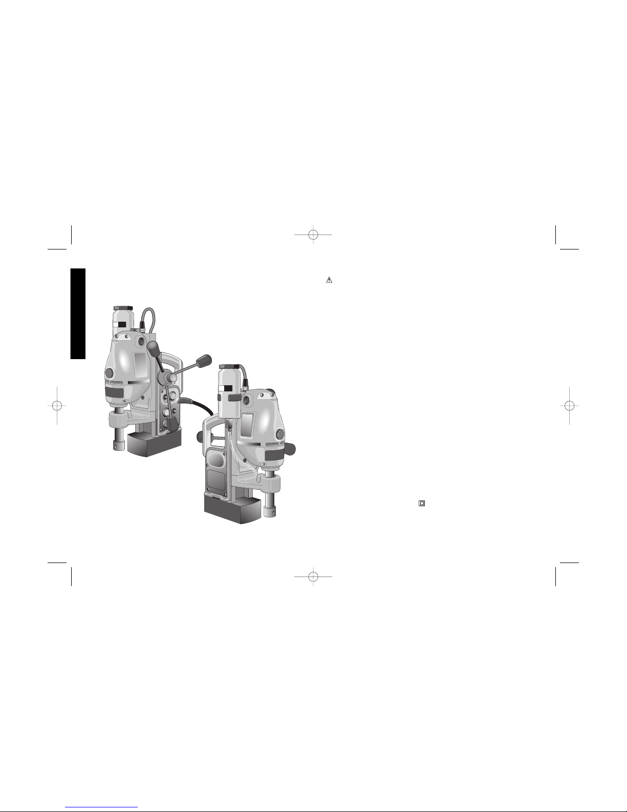
Operation
The magnet in this unit is designed for use on 3/8"(10mm) thick
steel—with zero air gap. Air gap may be defined as the distance
English
606564/DW151 10/1/02 10:20 AM Page 2
Page 6
between the magnet core surface and the mounting plate. The two
surfaces will be kept apart by curvature, coats of paint, by surface
irregularities, bolt heads, etc. Holding power is reduced by rough or
uneven surfaces, insufficient thickness of steel or insufficient
mounting area for the magnet base. The
magnet rapidly loses its holding power when
this surface irregularity raises the air gap above
1/64"(.4mm). Keep this air gap to a minimum
and be sure to smooth the surface removing
any undue projections, chips or other items that
will not allow full metal to metal contact. If the
magnet fails to hold on a metal surface, it may
be due to this condition and a check can be
made with a feeler gauge or similar device in
order to determine if an air gap exists under the
magnet at the crucial points.
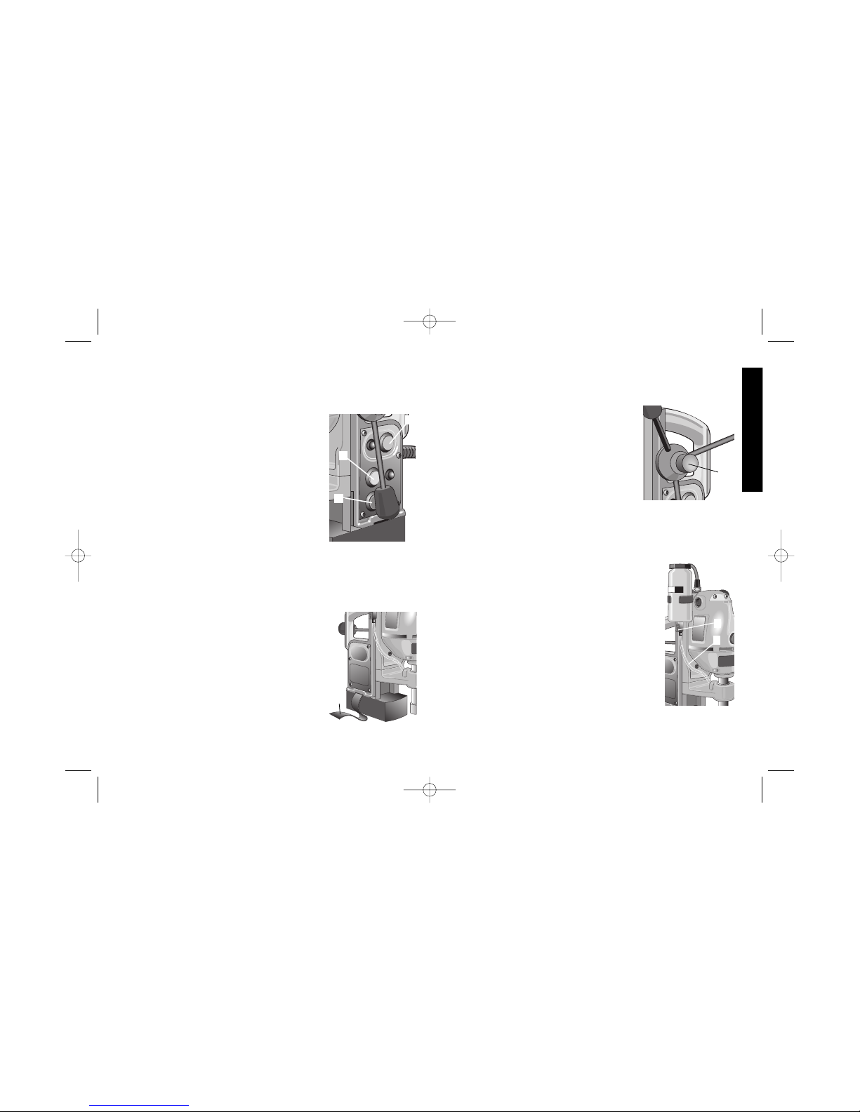
1. Place drill press on work surface so that drill
point or cutter pilot is directly over spot to be drilled. Push the red
button (A) to give power to the tool. Position the cutter directly over
the spot to be drilled and turn the magnet on by pressing the
yellow button (B). Turn power on to the motor by pressing the
green button (C). When drilling in an overhead or vertical position,
the safety strap (D) must be employed.
(Fitted in slot in base as shown)
NOTE: Replace strap if edges become frayed.
Inspect the strap before each use. New straps
are available at your retailer or D
EWALT service
center.
2. Gently apply pressure to feed handle until twist
drill or cutter has a full bite then apply steady
pressure until cut is complete.
3. Turn off motor and allow motor to run down
3
English
before turning magnet off.
4. Turn magnet off by pressing the yellow button. The magnet will
remain engaged for 5 seconds before releasing.
5. After each use, remove all chips from
magnet surface.
Operation with DEWALT
Annular Cutters
1. This unit was designed with user
convenience and safety in mind
2. User safety:
The switches are arranged to prevent
accidental motor start up before the magnet is energized.
The handles are arranged to allow for easy vertical and overhead
placement.
3. This unit comes equipped with a quick release feed handle (E). By
depressing a button, the feed handle can be
switched from the left to the right side of the unit.
The magnet is designed to adhere to 3/8”(10mm)
or greater thickness of flat steel or iron.
NOTE: DW151 can be adapted for use with twist
drill bits with addition of DW1561 Chuck Adapter.
4. Place proper pilot pin into desired cutter from the
top and insert cutter into the arbor. Line up cutter
flats with arbor set screws. Tighten both set
screws securely. (Make sure flats are properly
located under set screws so that they remain
recessed below surface of the shaft).
5. Fill reservoir with non oil-based cutting fluid. This
fluid is formulated to give the best performance
and life to the rotary cutters. Fluid will be released down pilot shaft
by gravity feed. Test by running cutter up and down against work
surface to start fluid flowing. Do not use liquid cutting fluids while
A
B
D
E
C
F
G
606564/DW151 10/1/02 10:20 AM Page 3
Page 7

drilling vertically or overhead. Dip cutter in cutting paste for these
applications..
NOTE: This unit features an on-board lubrication system. To use
the lubrication system, remove the hose (F) from the bottle by
depressing the black collar (G) into the bottle. Remove the hose
from the bottom of the petcock. Remove the bottle from the
bracket and fill with cutting fluid. Replace bottle in bracket and
replace hose. Turn the petcock counterclockwise to start the fluid.
Turn the petcock clockwise to close the valve when the cut is
finished. The bearings are lubricated by the on-board system.
WARNING: Do not pour cutting fluid into the bottle while
mounted in the bracket. Do not allow cutting fluid to enter the
drill motor. Electric shock may result.
6. Start motor by pressing the green button.
7. Bring cutter lightly to the surface to be cut allowing 25-30
revolutions, bringing up light chip so that cutter has established an
external groove. This will position you properly. Apply steady
pressure through the entire cut. It is more important to keep rpms
up than to apply excessive force, causing cutter to slow motor
down. This will attain better cutting action, better cutter life, and
cleaner holes.
8. Slug should be expelled on the down stroke. If not, it will be
expelled automatically when motor is returned to the extreme up
position.
CAUTION: Gloves should be worn when handling slugs to avoid
injury to the hand by hot surfaces or sharp edges.
Operation of Swivel Base (DW159)
1. Place unit on work surface sot that the point is near the center of
the hole to be drilled.
2. Push the red button to turn power on.
3. Push the yellow button to activate magnet.
4
English
4. Turn lever (H) counterclockwise to loosen the
swivel base.
5. Move the drill and rotate about the magnet
until the pilot pin is directly above the center
of the hole to be drilled.
6. Turn lever clockwise to tighten the swivel.
Operation of the Forward/Reverse
Feature (DW159)
The forward/reverse switch is a collar (I) on the top of the drill unit of
the DW159 only.
Control
Apply sufficient pressure to achieve a smooth, progressive cut. Do
not force unit. If magnet starts to lift from work plate, decrease
pressure slightly and it will reclamp. Drill point pressure may exceed
holding power under one or more of the following conditions:
1. Excessive air gap—1/64"(.4mm) or more.
2. Thin metal (under 3/8"(10mm) depending upon position and
condition of metal surface.)
3. Metal with low magnetic properties.
4. Uneven or rough surface.
H
I
606564/DW151 10/1/02 10:20 AM Page 4
Page 8

5
English
5. Low line voltage.
How To Drill
For accuracy drill a small lead hole before using the final size drill.
Large diameter drills will “walk” off center until drill reaches full
diameter at which point the outside diameter acts as a pilot in the
hole being drilled. This is not peculiar to magnetic drill presses, but
is general machine shop knowledge on any large hole drilling.
Brushes
Carbon brushes should be regularly inspected for wear. When the
cap is unscrewed, the spring and brush assembly may be withdrawn
from the tool.
Keep brushes clean and sliding freely in their guides. Carbon
brushes have varying symbols stamped into them, and if the brush
is worn down to the line closest to the spring, they must be replaced.
New brush assemblies are available at service centers.
Adjustments
This unit is designed with a lubricated gib and is adjusted at the factory.
The gib may by lubricated periodically with grease to ensure smooth
operation. The gib should be tight enough to retain the motor in the
upward (retracted) position. Should this need adjustment, tighten 5
self-locking set screws on the side of the drill press body.
Accessories
Recommended accessories for use with your tool are available at
extra cost from your distributor or your local service center.
CAUTION: The use of any non-recommended accessory may be
hazardous.
If you need assistance in locating any accessory, call us at:
1-800-4-D
EWALT or contact DEWALT Industrial Tool Co., 701 East
Joppa Road, Baltimore, MD 21286
1. DW1561 Chuck Adapter for DW151.
2. Mandrels and hole saws up to 2"(51mm) diameter.
3. Rotary cutters and pilots 7/16"(11mm) thru 2"(51mm) diameter.
4. Twist drill bits 1/4" (6mm) to 13/16" (21mm)
5. Taps 1/4" (6mm) to 13/16" (21mm)(DW159 only)
6. Reamers, Light Gauge 1/4" (6mm) to 5/8"(16mm)
Reamers, Heavy Gauge1/4" (6mm) to 1/2"(13mm)
Important
To assure product SAFETY and RELIABILITY, repairs, maintenance
and adjustment (including brush inspection and replacement) should
be performed by authorized service centers or other qualified service
organizations, always using identical replacement parts.
Full Warranty
D
EWALT heavy duty industrial tools are warranted for one year from
date of purchase. We will repair, without charge, any defects due to
faulty materials or workmanship. For warranty repair information, call
1-800-4-D
EWALT. This warranty does not apply to accessories or
damage caused where repairs have been made or attempted by
others. This warranty gives you specific legal rights and you may have
other rights which vary in certain states or provinces.
In addition to the warranty, D
EWALT tools are covered by our:
30 DAY NO RISK SATISFACTION GUARANTEE
If you are not completely satisfied with the performance of your
D
EWALT heavy duty industrial tool, simply return it to the participating
seller within 30 days for a full refund. Please return the complete
unit, transportation prepaid. Proof of purchase may be required.
FREE WARNING LABEL REPLACEMENT: If your warning labels
become illegible or are missing, call 1-800-4-DEWALT for a free
replacement.
606564/DW151 10/1/02 10:20 AM Page 5
Page 9

6
Français
SI VOUS AVEZ DES QUESTIONS OU VOUS VOULEZ NOUS FAIRE
PART DE VOS COMMENTAIRES CONCERNANT CET OUTIL OU
TOUT AUTRE OUTIL DEWALT, COMPOSEZ SANS FRAIS LE :
1 800 433-9258.
Règles de sécurité – Généralités
AVERTISSEMENT! Lire et comprendre toutes les directives, car le
non-respect des directives suivantes peut entraîner un choc
électrique, un incendie ou des blessures graves.
CONSERVER CES DIRECTIVES
ZONE DE TRAVAIL
· Garder la zone de travail propre et bien éclairée; les établis
encombrés et les endroits sombres sont propices aux accidents.
· Ne pas utiliser les outils électriques dans une atmosphère
explosive, comme à proximité de liquides, de gaz ou de
poussières inflammables; le moteur peut créer des étincelles et
enflammer les vapeurs ou les poussières environnantes.
· Tenir les enfants, les visiteurs ou toute autre personne
éloignés lorsqu’on utilise un outil électrique; les distractions
peuvent faire perdre la maîtrise de ce dernier.
MESURES DE SÉCURITÉ - ÉLECTRICITÉ
· Les outils mis à la terre doivent être branchés dans une prise
bien installée et mise à la terre conformément à tous les codes
et règlements en vigueur. Ne jamais retirer la broche de terre ni
modifier la fiche. Ne pas utiliser d'adaptateur. Vérifier auprès d'un
électricien qualifié en cas de doute quant à la mise à la terre de la
prise. En cas de défaillance électrique ou de bris de l'outil, la mise
à la terre procure un chemin de faible résistance au courant qui
autrement traverserait l'utilisateur. Cette protection ne s’applique
qu’aux outils de classe I (mis à la terre).
· Les outils à double isolation sont munis d’une fiche polarisée
POUR TOUT RENSEIGNEMENT SUPPLÉMENTAIRE SUR CET
OUTIL OU TOUT AUTRE OUTIL DEWALT, COMPOSER SANS
FRAIS LE NUMÉRO:
1 800 4-DEWALT (1 800 433-9258)
606564/DW151 10/1/02 10:20 AM Page 6
Page 10

7
Français
(c’est-à-dire que l’une des lames est plus large que l’autre),
laquelle ne peut être raccordée qu’à une prise polarisée et ce,
dans un seul sens; on doit l’inverser si on est incapable de
l’enfoncer complètement. Si la fiche ne s’adapte toujours pas,
on doit demander à un électricien qualifié d’installer la prise
appropriée. On ne doit jamais modifier la fiche. La double isolation
élimine le besoin d’installer un cordon d’alimentation trifilaire et un
système d’alimentation électrique pourvus d’une mise à la terre;
seuls les outils de classe II (à double isolation) sont munis d’une
telle protection.
· Éviter tout contact entre le corps et les éléments mis à la terre,
comme les tuyaux, les radiateurs, les cuisinières et les
réfrigérateurs, afin de réduire les risques de choc électrique.
· Ne pas utiliser l’outil électrique dans des endroits mouillés, ni
l’exposer à la pluie; l’infiltration d’eau à l’intérieur de l’outil
augmente les risques de choc électrique.
· Ne pas utiliser le cordon de manière abusive; on ne doit pas
transporter l’outil en le tenant par le cordon, ou utiliser ce
dernier pour le débrancher. On doit tenir le cordon éloigné des
sources de chaleur, de l’huile, des bords tranchants ou des pièces
mobiles. Remplacer immédiatement les cordons endommagés, car
ces derniers augmentent les risques de choc électrique.
· Lorsqu’on utilise un outil électrique à l’extérieur, on ne doit utiliser
que des rallonges conçues pour cet usage, comme celles de type
W-A ou W, afin de réduire les risques de choc électrique.
Calibre minimal des cordons de rallonge
Longueur totale du cordon
25 ft. 50 ft. 75 ft. 100 ft. 125 ft. 150 ft. 175 ft.
7,6 m 15,2 m 22,9 m 30,5 m 38,1 m 45,7 m 53,3 m
Intensité
18 AWG 18 AWG 16 AWG 16 AWG 14 AWG 14 AWG 12 AWG
10- 12 16 16 14 12
12- 16 14 12 Non recommandé
SÉCURITÉ PERSONNELLE
· Rester vigilant en tout temps et faire preuve de jugement
lorsqu’on utilise un outil électrique; ne pas utiliser l’outil lorsqu’on
est fatigué ou sous l’influence de drogues, d’alcool ou de
médicaments, car un moment d’inattention peut entraîner des
blessures graves.
· Porter des vêtements appropriés; ne pas porter de vêtements
amples ni de bijoux. Couvrir ou attacher les cheveux longs. Garder les
cheveux, les vêtements, les bijoux et les gants éloignés des pièces
mobiles, car ceux-ci peuvent s’y coincer.
· Éviter les démarrages accidentels; s’assurer que l’interrupteur soit
en position d’arrêt avant de brancher l’outil. Ne pas transporter l’outil
en laissant le doigt sur l’interrupteur ni le brancher lorsque l’interrupteur
est en position de marche, car cela pourrait causer un accident.
· Retirer les clés de réglage avant de démarrer l’outil; une clé laissée
sur une pièce rotative peut entraîner des blessures.
· Ne pas trop étendre les bras; les pieds doivent rester ancrés
fermement au sol afin de maintenir son équilibre en tout temps et de
mieux maîtriser l’outil dans des situations imprévues.
· Utiliser le matériel de sécurité approprié; toujours porter des
lunettes de protection. Porter un masque anti-poussières, des
chaussures antidérapantes, un casque de sécurité ou des protecteurs
auditifs lorsque la situation le requiert.
UTILISATION ET ENTRETIEN DE L’OUTIL
· Fixer et soutenir la pièce sur une plate-forme stable au moyen
d’une butée fixe ou de tout autre dispositif semblable; la pièce est
instable lorsqu’on la retient manuellement ou qu’on l’appuie contre le
corps, ce qui peut faire perdre la maîtrise de l’outil.
· Ne pas forcer l’outil ni l’utiliser pour des travaux autres que ceux
pour lesquels il a été conçu. Pour obtenir de meilleurs résultats et
prévenir les risques de blessure, laisser l’outil couper à la vitesse pour
laquelle il a été conçu.
· Ne pas utiliser l’outil lorsque l’interrupteur marche-arrêt ne
fonctionne pas; tout outil qui ne peut être commandé au moyen de
606564/DW151 10/1/02 10:20 AM Page 7
Page 11

8
Français
l’interrupteur est dangereux et doit être réparé.
· Débrancher l’outil avant d’effectuer un réglage, de changer les
accessoires ou de ranger l’outil; ces mesures de sécurité
préventives réduisent les risques de démarrage accidentel.
· Lorsqu’on n’utilise pas l’outil, le ranger hors de la portée des
enfants ou des personnes non qualifiées; les outils sont dangereux
entre les mains de personnes inexpérimentées.
· Bien entretenir l’outil et s’assurer qu’il soit toujours bien propre
et aiguisé; les outils bien entretenus et dont les bords sont bien
tranchants sont moins susceptibles de rester coincés et sont plus
faciles à maîtriser.
· Vérifier les pièces mobiles afin de s’assurer qu’elles soient bien
alignées et qu’elles ne restent pas coincées; vérifier également les
pièces afin de s’assurer qu’il n’y ait ni bris ni aucune autre condition
susceptible de nuire au bon fonctionnement de l’outil; faire réparer
l’outil si ce dernier est endommagé avant de s’en servir à nouveau, car
les accidents sont souvent causés par des outils mal entretenus.
· N’utiliser que les accessoires recommandés par le fabricant pour
le modèle en question; un accessoire destiné à un outil particulier
peut devenir dangereux lorsqu’il est utilisé avec un autre.
ENTRETIEN
· L’outil doit être entretenu par le personnel qualifié seulement;
toute maintenance effectuée par une personne non qualifiée peut
entraîner des risques de blessure.
· Lors de l’entretien, n’utiliser que des pièces de rechange
identiques et suivre les directives de la section «Entretien» du
présent manuel afin de prévenir les risques de choc électrique ou de
blessure.
Consignes de sécurité additionnelles
· Toujours utiliser la courroie de sécurité, car la base pourrait se
dégager. L’alimentation électrique risque d’être coupée si l’outil est
débranché accidentellement.
· Toujours s’assurer que la perceuse à colonne est enfichée dans
une prise ayant la tension appropriée. Placer le cordon de manière
à éviter de le débrancher accidentellement; s’assurer que le fusible du
circuit convient à l’outil.
· Avant de faire fonctionner l’outil, s’assurer qu’il est bien mis à la
terre, conformément à la section « Directives de mise à la terre » du
présent guide.
· Toujours utiliser une rallonge de calibre approprié.
· S’assurer de placer la base de l’outil sur une surface plane; ne pas
déposer l’aimant sur des objets tels que les têtes de boulons, les vis,
les rivets ou les copeaux d’acier puisque l’espace entre l’aimant et la
surface de travail affaiblit sa capacité d’adhérence.
· Toujours placer l’outil sur une surface exempte de particules, de
copeaux et de poussière afin d’optimiser sa capacité d’adhérence.
AVERTISSEMENT! Porter des lunettes de sécurité ou autre dispositif
de protection oculaire car le martelage peut faire projeter des
particules et entraîner des dommages irréversibles aux yeux.
MISE EN GARDE : NE PAS SOULEVER L’OUTIL AU MOYEN DE LA
POIGNÉE D’ALIMENTATION.
MISE EN GARDE : la base magnétique adhère à la surface pendant
5 secondes une fois que l’aimant est mis hors tension; frapper légèrement
la base avec la main afin de détacher l’aimant.
AVERTISSEMENT : certains outils électriques, tels que les sableuses,
les scies, les meules, les perceuses ou certains autres outils de
construction, peuvent produire de la poussière contenant des produits
chimiques susceptibles d’entraîner le cancer, des malformations
congénitales ou pouvant être nocifs pour le système reproductif. Parmi
ces produits chimiques, on retrouve :
· le plomb dans les peintures à base de plomb,
· a silice cristalline dans les briques et le ciment et autres produits
de maçonnerie,
· l’arsenic et le chrome dans le bois de sciage ayant subi un traitement
chimique (comme l’arséniate de cuivre et de chrome).
Le risque associé à de telles expositions varie selon la fréquence avec
laquelle on effectue ces travaux. Pour réduire l’exposition à de tels
produits, il faut travailler dans un endroit bien aéré et utiliser le matériel
606564/DW151 10/1/02 10:20 AM Page 8
Page 12

9
Français
de sécurité approprié, tel un masque anti-poussières spécialement
conçu pour filtrer les particules microscopiques.
• Éviter tout contact prolongé avec la poussière soulevée par cet
outil ou autres outils électriques. Porter des vêtements de
protection et nettoyer les parties exposées du corps avec de l'eau
savonneuse. S'assurer de bien se protéger afin d'éviter d'absorber par
la bouche, les yeux ou la peau des produits chimiques nocifs.
Moteur
Cet outil est entraîné par un moteur DEWALT. On doit s’assurer que
l’intensité nominale du cordon d’alimentation correspond à celle
indiquée sur la plaque signalétique; sur cette dernière, la mention «
60 Hz » ou « c. a. seulement » signifie que l’outil ne doit être branché
que dans une prise de courant alternatif de 60 Hz, et non pas dans une
prise de courant continu. Une chute de tension de plus de 10 %
pourrait entraîner une perte de puissance et une surchauffe de plus
de 10 %. Tous les outils D
EWALT sont soumis à des essais en usine;
si cet outil ne fonctionne pas, vérifier la source d’alimentation
électrique. Si le moteur ne fonctionne pas lorsqu’on appuie sur le
bouton vert, vérifier la tension de la source d’alimentation.
Fonctionnement
Cet outil est doté d’un aimant destiné à être utilisé sur une surface en
acier de 10 mm (3/8 po) d’épaisseur dépourvue
d’une couche d’air. Le terme « couche d’air »
décrit la distance entre la surface de l’âme d’un
aimant et la plaque d’assemblage. Les deux
surfaces doivent être tenues séparées au moyen
d’une courbure, d’une couche de peinture, d’une
déformation verticale, d’une tête de boulon et
ainsi de suite. La capacité d’adhérence de
l’aimant est réduite par les surfaces
rugueuses ou inégales ou par l’épaisseur
insuffisante de l’acier ou de la surface sur laquelle la base magnétique
est assemblée. L’aimant perd rapidement sa capacité d’adhérence
lorsque la déformation verticale augmente la
couche d’air au-dessus de 0,4 mm (1/64 po). On
doit donc réduire autant que possible la couche
d’air et rendre la surface lisse en enlevant les
projections, les copeaux ou autres éléments
susceptibles d’empêcher le contact entre les
métaux. Si l’aimant n’adhère pas à la surface
métallique, vérifier si le contact se fait au moyen
d’une jauge d’épaisseur ou d’un dispositif
semblable afin de déterminer s’il existe une
couche d’air aux endroits critiques situés sous
l’aimant.
1. Mettre la perceuse à colonne sur la surface de travail de manière à
orienter la pointe ou la goupille de retenue directement au-dessus
de la zone à percer. Mettre l’outil sous tension en appuyant sur le
bouton rouge (A), puis placer la pointe de coupe directement audessus de la zone à percer. Mettre l’aimant en marche en enfonçant
le bouton jaune (B). Mettre le moteur sous tension en appuyant sur
le bouton vert (C). On doit utiliser la courroie de sécurité (D)
lorsqu’on perce un trou en position verticale ou au plafond (la
courroie est fixée dans la fente située dans la base de l’outil, tel
qu’illustré).
REMARQUE : remplacer la courroie si les bords deviennent effilochés.
Inspecter la courroie avant chaque utilisation. On peut se procurer de
nouvelles courroies chez un détaillant local ou à un centre de service
D
EWALT.
2. Exercer une légère pression sur la poignée d’alimentation jusqu’à ce
que la mèche hélicoïdale ou la pointe de coupe morde dans la
pièce, puis appliquer une pression constante jusqu’à ce que la
coupe soit terminée.
3. Arrêter le moteur et attendre qu’il décélère avant de mettre l’aimant
D
A
B
C
606564/DW151 10/1/02 10:20 AM Page 9
Page 13

10
Français
hors tension.
4. Mettre l’aimant hors tension en appuyant sur le bouton jaune
(l’aimant continuera d’adhérer
à la surface pendant 5 secondes avant de se détacher).
5. Après chaque utilisation, retirer tous les copeaux qui se sont
accumulés sur la surface magnétique.
Fonctionnement des
perceuses avec une
pointe de coupe annulaire
D
EWALT
1. Cet outil pratique est conçu pour être
utilisé en toute sécurité.
2. Sécurité de l’utilisateur :
Les interrupteurs sont disposés de manière
à empêcher le démarrage accidentel du
moteur avant la mise sous tension de l’aimant.
Les poignées sont disposées de manière à permettre à l’utilisateur de
travailler facilement en position verticale ou au plafond.
3. L’outil est muni d’une poignée d’alimentation à dégagement rapide
(E). On peut déplacer la poignée du côté gauche au côté droit de
l’outil en appuyant tout simplement sur un bouton.
L’aimant est destiné à être utilisé sur une surface plane en acier ou de
fer de 10 mm (3/ 8 po) d’épaisseur.
REMARQUE : on peut adapter le modèle DW151 afin de pouvoir
l’utiliser avec des mèches hélicoîdales munies d’un porte-mandrin
modèle DW1561.
4. Installer la goupille de retenue appropriée dans la pointe de coupe
sélectionnée, à partir du haut, puis introduire la pointe dans la tige.
Aligner les surfaces planes de la pointe de coupe avec les vis de
retenue de la tige. Bien serrer les deux vis de retenue, en s’assurant
que les surfaces planes sont bien placées sous les vis de manière
à ce qu’elles soient en retrait sous la surface de l’arbre.
5. Remplir le réservoir de fluide de coupe à base
d’huile. Ce fluide est formulé en vue d’optimiser
le rendement et la durée de vie des pointes de
coupe rotatives. Le fluide est alimenté par gravité
dans l’arbre pilote. Vérifier le fonctionnement de
l’outil en le déplaçant verticalement contre la
surface de travail afin de faire écouler le fluide.
Lorsqu’on réalise une coupe en position verticale
ou au plafond, tremper la pointe dans une pâte
D
EWALT.
REMARQUE : cet outil est doté d’un système de
lubrification intégré. Pour utiliser ce système, retirer le
boyau (F) de la bouteille en enfonçant le collier noir
(G) dans celle-ci. Enlever le boyau situé au fond du
robinet de purge, puis dégager la bouteille de sa ferrure et la remplir de
fluide de coupe. Remettre la bouteille dans la ferrure et replacer le
boyau. Tourner le robinet de purge vers la gauche pour faire circuler le
fluide, puis vers la droite pour fermer le robinet une fois la coupe
terminée. Les roulements sont lubrifiés au moyen de ce système.
AVERTISSEMENT : ne verser aucun fluide dans la bouteille
lorsque celle-ci est installée dans la ferrure, ni ne laisser aucun fluide
pénétrer à l’intérieur du moteur de l’outil afin d’éviter les risques de
choc électrique.
Appliquer fréquemment une grande quantité d’huile sur les roulements
afin de les maintenir graissés en tout temps.
6. Démarrer le moteur en appuyant sur le bouton vert.
7. Déplacer lentement la pointe de coupe vers la zone à couper, en
laissant tourner l’outil de 25 à 30 révolutions. L’outil projettera de fins
copeaux lorsque la pointe pratique une rainure externe. Une fois la
position de l’outil bien établie, exercer une pression constante
jusqu’à ce que la coupe soit terminée. Il est plus important de
maintenir une vitesse de rotation élevée plutôt que d’exercer une
trop forte pression, ce qui a pour effet de ralentir le moteur. Cette
façon de procéder aide à améliorer la coupe, à prolonger la durée
E
F
G
606564/DW151 10/1/02 10:20 AM Page 10
Page 14

11
Français
de vie de la pointe et à produire des orifices plus précis.
8. Les copeaux de métal doivent être expulsés lorsqu’on abaisse l’outil;
sinon, ils seront automatiquement expulsés lorsqu’on soulève
complètement le moteur.
MISE EN GARDE : on doit porter des gants lorsqu’on manipule les
copeaux afin d’éviter de subir des blessures aux mains lorsqu’elles
entrent en contact avec les surfaces chaudes ou les bords tranchants.
Fonctionnement de la base pivotante
(DW159)
1. Placer l’appareil sur la surface de travail de manière à orienter la
pointe près du centre du trou à percer.
2. Enfoncer le bouton rouge afin de mettre l’appareil en marche.
3. Appuyer sur le bouton jaune pour actionner l’aimant.
4. Tourner le levier (H) vers la gauche pour desserrer la base
pivotante.
5. Déplacer la perceuse et tourner l’aimant de manière à placer la
goupille de retenue directement au-dessus du centre du trou à
percer.
6. Tourner le levier vers la droite pour resserrer la base pivotante.
Fonctionnement de l’interrupteur de
marche avant ou marche arrière (DW159)
Le collier (I) situé au-dessus de la perceuse (modèle DW159
seulement) sert d’interrupteur de marche avant ou marche arrière.
Commandes
Appliquer suffisamment de pression pour assurer un perçage précis;
ne pas forcer l’outil. Si l’aimant semble vouloir se détacher de la
surface de travail, diminuer légèrement la pression afin de bien l’y
adhérer. La pression exercée peut dépasser la capacité d’adhérence
en présence de l’une ou de plusieurs des conditions suivantes :
1. une couche d’air excessive (de 0,4 mm ou 1/ 64 po ou plus);
2. une tôle mince (d’une épaisseur inférieure à 10 mm ou 3/ 8 po (selon
la position et la condition de la surface métallique);
3. une pièce en métal ayant de faibles propriétés magnétiques;
4. une surface inégale ou rugueuse;
5. une faible tension électrique.
Perçage
Afin de réaliser une coupe précise, percer un avant-trou avant d’utiliser
la mèche voulue. Les mèches de grand diamètre ont tendance à
s’éloigner du centre avant d’atteindre le plein diamètre de l’orifice; le
diamètre de ce trou devient alors le « pilote » lorsqu’on effectue le
perçage. Cette situation n’est pas limitée aux perceuses magnétiques
à colonne; en effet, cela arrive fréquemment dans les ateliers
d’usinage lorsque les ouvriers percent de grands trous.
Balais
Inspecter régulièrement les balais de charbon afin de s’assurer qu’il n’y
a aucun signe d’usure. Lorsque le capuchon est dévissé, on peut
retirer l’ensemble ressort/balai de l’outil.
Maintenir les balais propres afin qu’ils puissent glisser librement dans
leurs guides. Divers symboles apparaissent sur les balais; on doit
remplacer ces derniers lorsque l’usure atteint la ligne la plus près du
ressort. De nouveaux balais sont offerts aux centres de service
H
I
606564/DW151 10/1/02 10:20 AM Page 11
Page 15

12
Français
autorisés.
Réglages
Cet outil est doté d’une cale lubrifiée en permanence et réglée en
usine. La cale peut être lubrifiée périodiquement au moyen de graisse
afin d’assurer qu’elle fonctionne correctement, et doit être
suffisamment serrée pour retenir le moteur en position verticale
(escamotée). Pour effectuer un réglage, serrer les cinq vis de retenue
à verrouillage automatique fixées sur la partie latérale du corps de
l’outil.
Accessoires
Les accessoires recommandés pour cet outil sont vendus séparément
chez tous les distributeurs ou dans tous les centres de service
autorisés.
MISE EN GARDE : l’utilisation d’accessoires autres que ceux qui
sont recommandés pourrait présenter un danger.
Pour obtenir plus d’information sur les accessoires, communiquer avec
D
EWALT Industrial Tool Co., 701 East Joppa Road, Baltimore, MD
21286, aux États- Unis ou composer le 1 800 433- 9258. Parmi ces
accessoires, on retrouve :
1. un porte-mandrin modèle DW1561 (pour le modèle DW151);
2. des mandrins (« mandrels ») et des scies à trous de 51 mm (2 po)
de diamètre ou moins;
3. des pointes de coupe rotatives et des pilotes de 11 mm (7/ 16 po) à
51 mm (2 po) de diamètre;
4. des mèches hélicoïdales de 6 mm (1/4 po) à 21 mm (13/16 po);
5. des tarauds de 6 mm (1/ 4 po) à 21 mm (13/ 16 po) de diamètre
(pour le modèle DW159 seulement);
6. des alésoirs de faible calibre de 6 mm (1/ 4 po) à 16 mm (5/ 8 po)
de diamètre et des alésoirs de fort calibre de 6 mm (1/ 4 po) à 13
mm (1/ 2 po) de diamètre.
Important
Pour assurer la SÉCURITÉ et la FIABILITÉ de cet outil, toutes les
opérations de réparation, d’entretien et de réglage doivent être
effectuées dans un centre de service autorisé ou par du personnel
qualifié (cela comprend l’inspection et le remplacement du balai); on ne
doit utiliser que des pièces de rechange identiques.
Garantie complète
DEWALT garantit les outils industriels de service intensif contre tout
défaut de matériel ou de fabrication pour une période d’un an à
compter de la date d’achat; le produit défectueux sera réparé sans
frais. Pour obtenir de plus amples renseignements sur les réparations
couvertes par la présente garantie, composer le 1 800 433-9258. Cette
garantie ne s’applique pas aux accessoires et ne vise pas les
dommages causés par des réparations effectuées par un tiers. Cette
garantie confère des droits légaux particuliers à l’acheteur, mais celuici pourrait aussi bénéficier d’autres droits variant d’un territoire à l’autre.
En plus de la présente garantie, la
GARANTIE SANS RISQUE DE 30 JOURS EN CAS DE NON-
SATISFACTION
s’applique également aux outils D
EWALT.
Si l’acheteur n’est pas entièrement satisfait du rendement de l’outil
industriel de service intensif D
E
WALT, celui-ci peut le retourner au
vendeur participant dans les 30 jours pour obtenir un remboursement
intégral. Retourner l’outil au complet en payant le transport à l’avance;
une preuve d’achat peut être requise.
REMPLACEMENT GRATUIT DE L'ÉTIQUETTE
Si vos étiquettes d'avertissement deviennent illisibles ou sont
manquantes, composez le 1-800-4-D
EWALT pour obtenir une étiquette
de remplacement gratuite.
606564/DW151 10/1/02 10:20 AM Page 12
Page 16

13
Español
SI TIENE CUALQUIER PREGUNTA O COMENTARIO ACERCA DE
ESTA O CUALQUIER OTRA HERRAMIENTA DEWALT, POR FAVOR
LLÁMENOS AL: 326-7100
SI TIENE PREGUNTAS O COMENTARIOS SOBRE ESTA U OTRA
HERRAMIENTA DEWALT, LLÁMENOS GRATIS AL:
1-800-4-DEWALT (1-800-433-9258)
Reglas generales de seguridad
¡ADVERTENCIA! Lea y entienda todo el instructivo. El no seguir
todas las instrucciones enumeradas a continuación puede resultar en
electrochoque, fuego y/o seria lesión personal.
GUARDE ESTAS INSTRUCCIONES
ÁREA DE TRABAJO
· Mantenga su área de trabajo limpio y bien iluminado. Bancos de
trabajo abarrotados de cosas y áreas oscuras son una invitación a los
accidentes.
· No opere herramientas eléctricas en atmósferas explosivas,
donde hay presencia de líquidos, gases, o polvos inflamables.
Las herramientas eléctricas crean chispas que podrían encender el
polvo o los gases.
· Mantenga a los transeúntes, niños, y visitantes alejados mientras
opera una herramienta eléctrica. Las distracciones podrían causar
la pérdida de control.
SEGURIDAD ELÉCTRICA
· Herramientas a tierra deberán conectarse a un tomacorriente Las
instalado correctamente y puesto a tierra de acuerdo con todos
los códigos y ordenanzas. Nunca debe quitar el clavijero de tierra o
modificar el enchufe de algún modo. No usar enchufes adaptadores.
Infórmese con un electricista competente si duda que el tomacorriente
esté adecuadamente puesto a tierra. Si las herramientas funcionan
mal eléctricamente, o fallan, la puesta a tierra provee una vía de
resistencia baja que aparta del usuario la electricidad extraída. Sólo
aplica a la Clase I herramientas (a tierra).
· Las herramientas con doble aislamiento están equipadas con un
enchufe polarizado (una clavija es más ancha que la otra.) Este
enchufe encajará en un tomacorriente polarizado de una sola
606564/DW151 10/1/02 10:20 AM Page 13
Page 17

14
Español
SEGURIDAD PERSONAL
· Manténgase alerta, observe lo que está haciendo y use sentido
común al usar una herramienta eléctrica. No la use cuando esté
cansado o bajo la influencia de drogas, alcohol, o medicinas. Un
instante de inatención mientras opera herramientas eléctricas puede
resultar en serias lesiones personales.
· Vístase adecuadamente. No use vestimenta suelta o joyas.
Mantenga el cabello largo sujeto. Mantenga su cabello, vestimenta
y guantes apartados de piezas en movimiento. La vestimenta suelta,
las joyas o el cabello largo podrían quedar atrapados en las partes en
movimiento.
· Evite un arranque accidental. Asegúrese de apagar la herramienta
antes de enchufarla. El cargar las herramientas con el dedo en el
interruptor o enchufar herramientas que tienen el interruptor activado
es una invitación a los accidentes.
· Quite las llaves de ajuste antes de activar la herramienta. Una llave
que se deja anexada a una parte giratoria de la herramienta puede
resultar en lesión personal.
· No se extralimite. Mantenga la pisada firme y el balance apropiado
todo el tiempo. El pie bien afincado y el balance apropiado permite un
mejor control de la herramienta en situaciones inesperadas.
· Utilice equipo de seguridad. Use siempre protección para los ojos.
Se deberá usar máscara contra el polvo, calzado protector antirresbalante, casco, o protector de oído en las condiciones que los
justifican.
USO Y CUIDADO DE HERRAMIENTAS
· Utilice tornillos de banco u otra forma práctica para sujetar y
apoyar la pieza de trabajo a una plataforma estable. Sujetar la
pieza manualmente o contra su cuerpo es inestable y puede llevar a
la pérdida de control.
· No fuerce la herramienta. Use la herramienta correcta para la
aplicación. La herramienta correcta hará una labor mejor y más
segura, con la energía nominal para la cual fue diseñada.
· No use la herramienta si el interruptor no prende y apaga. La
manera. Si el enchufe no encaja bien en el tomacorriente, invierta
el enchufe. Si todavía no encaja, contacte a un electricista
competente para que instale un tomacorriente polarizado. No
cambie el enchufe. El aislamiento doble elimina la necesidad de un
cable eléctrico a tierra de tres alambres y un sistema de alimentación
eléctrica puesto a tierra. Sólo aplica a la Clase II herramientas
(aislamiento doble).
· Evite que su cuerpo haga contacto con superficies a tierra tales
como tuberías, radiadores, cocinas, y refrigeradoras. Existe un
mayor riesgo de electrochoque.
· No exponga las herramientas eléctricas a la lluvia o condiciones
húmedas. La penetración de agua a una herramienta eléctrica
incrementará el riesgo de electrochoque
· No maltrate el cable. No lo use nunca para acarrear las herramientas
o halar el enchufe de un tomacorriente. Mantenga el cable alejado del
calor, aceite, bordes afilados o partes en movimiento. Reemplace
inmediatamente los cables dañados. Los cables dañados incrementan el riesgo de electrochoque.
· Al operar una herramienta eléctrica a la intemperie, use un cable
de extensión para exteriores marcado “W-A” o “W.” Estos cables
están hechos para uso exterior y reducen el riesgo de electrochoque.
Calibre mínimo para juegos de cables
Voltios Largo total del cable en pies
120V 0-25 26-50 51-100 101-150
240V 0-50 51-100 101-200 201-300
Amperaje nominal
Más No más AWG
de de
0- 6 18 16 16 14
6 - 10 18 16 14 12
10- 12 16 16 14 12
12 - 16 14 12 No recomendado
606564/DW151 10/1/02 10:20 AM Page 14
Page 18

15
Español
herramienta que no se puede controlar con el interruptor es peligrosa
y debe ser reparada.
· Desconecte el enchufe de la toma de corriente antes de efectuar
cualquier ajuste, cambio de accesorios, o guardar la herramienta.
Estas medidas de seguridad preventivas reducen el riesgo a que la
herramienta arranque accidentalmente.
· Mantenga herramientas que no estén en uso fuera del alcance
de los niños y otras personas no entrenadas. Las herramientas
son peligrosas en manos de usuarios no entrenados.
· Las herramientas deben recibir un mantenimiento cuidadoso.
Mantenga las herramientas para corte afiladas y limpias. Las
herramientas bien cuidadas con bordes de corte afilados son menos
susceptibles a trabarse y más fáciles de controlar.
· Revise si hay desalineación o traba en las partes movibles, partes
rotas u otra condición que pueda afectar la operación de la
herramienta. De estar dañada, dar servicio a la misma antes de
utilizarla. Muchas veces la causa de accidentes se debe a
herramientas con poco mantenimiento.
· Use solamente los accesorios que el fabricante recomienda para
su modelo. Los accesorios adecuados para una herramienta, pueden
resultar peligrosos cuando se usa en otra.
SERVICIO
· El servicio a la herramienta debe ser realizado por personal de
reparación calificado únicamente. El servicio o mantenimiento
efectuado por personal no calificado puede entrañar un riesgo o lesión.
· Al dar servicio a la herramienta, use sólo piezas de repuesto
idénticas. Siga las instrucciones contenidas en la sección
Mantenimiento de este manual. El uso de repuestos no autorizados o
el no cumplir con las instrucciones de Mantenimiento puede crear el
riesgo de electrochoque o lesión.
Instrucciones adicionales de seguridad
• Utilice siempre la banda de seguridad. El montaje puede soltarse.
La corriente eléctrica puede fallar o la unidad puede desconectarse
accidentalmente.
• Asegúrese siempre que el taladro de columna esté conectado a
un sistema con el voltaje adecuado. Coloque el cable de manera
que no pueda desconectarse de la toma de corriente por accidente.
Verifique que la líneas tenga el fusible adecuado.
• Antes de operar la unidad, asegúrese que esté aterrizada
correctamente según las instrucciones bajo “Seguridad eléctrica”.
• Utilice siempre cables de extensión con el calibre adecuado.
• Tenga cuidado de colocar la base en una superficie plana. No
coloque el magneto sobre objetos tales como tornillos, remaches,
pernos, rebabas, etc., ya que el espacio entre el magneto y la
superficie de trabajo debilita la atracción magnética.
• Siempre coloque la unidad sobre una superficie libre de rebabas,
astillas o suciedad para lograr el óptimo agarre magnético.
PRECAUCIÓN: Utilice la protección auditiva adecuada durante el
uso de esta unidad. Bajo ciertas condiciones y duración de3 uso, el
ruido producido por este producto puede contribuir a la pérdida
auditiva.
PRECAUCIÓN: NO UTILICE EL MANGO DE ALIMENTACIÓN PARA
LEVANTAR LA UNIDAD
PRECAUCIÓN: Después de cortar la corriente al magneto, la base
magnética continuará adherida a la superficie de trabajo durante 5
segundos antes de soltarse. Un golpe ligero con la mano liberará la
base.
ADVERTENCIA: El polvo originado por lijar, aserrar, esmerilar,
taladrar y otras actividades constructivas contiene productos químicos
que se sabe causan cáncer, defectos congénitos u otros daños
reproductivos. Algunos ejemplos de estos químicos son:
• plomo de pinturas con base de plomo.
• sílice cristalino de ladrillos y cemento y otros productos de
mampostería, y
• arsénico y cromo de madera tratada químicamente (CCA).
Su riesgo de exposición variará de acuerdo a la frecuencia con
que efectúe este tipo de trabajos. Para reducir su exposición a
estos químicos: trabaje en un área bien ventilada, y trabaje con
606564/DW151 10/1/02 10:20 AM Page 15
Page 19

16
Español
condiciones; usted puede verificar que no haya
colchón de aire debajo del magneto en los puntos
cruciales con un calibrador de laminillas u otro
dispositivo similar.
1. Coloque el taladro de columna sobre la
superficie de manera que la punta o el piloto
de el cortador quede directamente sobre el
punto en que se perforará. Encienda la unidad
oprimiendo el botón rojo (A). Coloque el
cortador directamente sobre el punto a
perforar y encienda el magneto, oprimiendo el
botón amarillo (B). Encienda el motor
oprimiendo el botón verde (C). Cuando
perfore sobre su cabeza o en posición
vertical, debe usar siempre la banda de
seguridad (D). (Colocada en la ranura de la
base, como se ilustra.)
NOTA: reemplace la banda si las orillas se
ven raídas. Inspeccione la banda antes de
cada uso. Hay bandas nuevas a su
disposición con el distribuidor o en el centro
de servicio de su localidad.
2. Aplique un poco de presión en el volante de
alimentación hasta que la broca o el cortador penetren y después
aplique presión uniforme hasta completar el corte.
3. Apague el motor y permita que se detenga antes de desconectar
el magneto.
4. Apague el magneto oprimiendo el botón amarillo. El magneto
permanecerá activado durante 5 segundos y emitirá un sonido
antes de soltarse.
5. Después de cada uso, quite todas las rebabas de la superficie del
magneto.
equipo de seguridad aprobado, tal como máscaras contra polvo
diseñadas específicamente para filtrar partículas microscópicas.
• Evite el contacto prolongado con polvos originados por lijar,
aserrar, esmerilar, taladrar y otras actividades constructivas. Vista
ropas protectoras y lave las áreas expuestas con agua y jabón.
Permitir que el polvo se introduzca en su boca, ojos, o dejarlo sobre la
piel promueve la absorción de químicos dañinos.
Motor
Su herramienta DEWALT funciona con un motor DEWALT. Asegúrese
que la alimentación concuerde con las indicaciones de la placa de
identificación.
Volts 60 Hz o “AC only” significa que su herramienta debe operarse
solamente con corriente alterna y nunca con corriente directa.
Disminuciones en el voltaje de 10% o mayores causarán pérdida de
potencia y sobre calentamiento. Todas las herramientas D
EWALT se
prueban en la fábrica; si esta herramienta no funciona, revise la
alimentación de corriente. Si el motor no funciona al oprimir el botón
verde, revise el voltaje en la toma de corriente.
Operación
El magneto de esta unidad está diseñado para usarse en acero de 10
mm (3/8”) de espesor–sin colchón de aire. El colchón de aire puede
definirse como la distancia entre la superficie del magneto y la placa
de montaje. Las dos superficies pueden quedar separadas debido a
curvaturas, capas de pintura, irregularidades en la superficie, cabezas
de tornillos, etc. La fuerza de sujeción se reduce en superficies
rugosas o desniveladas, debido a espesor insuficiente del acero o área
de montaje insuficiente para la base del magneto. El magneto pierde
rápidamente su fuerza de sujeción cuando estas irregularidades
incrementan el colchón de aire a más de 0.4 mm (1/64”). Conserve al
mínimo este colchón de aire y asegúrese de alisar la superficie
eliminando cualquier proyección indebida, rebabas o cualquier otra
cosa que no permita el contacto completo de metal con metal. Si el
magneto falla para sujetarse a una superficie, puede deberse a estas
A
B
D
C
606564/DW151 10/1/02 10:20 AM Page 16
Page 20

17
Español
Operación con cortadores anulares
D
EWALT
1. Esta unidad se diseñó teniendo en mente la comodidad y la
seguridad del operador.
2. Seguridad del operador:
Los interruptores se han dispuesto para evitar que el operador
encienda el motor accidentalmente antes
de energizar el magneto.
Los mangos están dispuestos para permitir
su fácil colocación en posiciones vertical y
por arriba de la cabeza.
3. Esta unidad viene equipada con un volante
de alimentación de liberación rápida (E).
Con el simple movimiento de oprimir un
botón, se puede cambiar del lado izquierdo
al lado derecho de la unidad.
El magneto está diseñado para adherirse a placas de acero o hierro
con espesor de 10 mm (3/8”) o mayor.
NOTA: El modelo DW151 puede adaptarse para emplear brocas
helicoidales con la adición del adaptador de
broquero DW1561.
4. Coloque el perno piloto apropiado en el cortador
que desee a partir de la punta e inserte el
cortador en el eje. Haga coincidir los planos del
cortador con los prisioneros. Apriete con firmeza
ambos prisioneros. (Asegúrese que ambos
planos estén correctamente colocados bajo los
prisioneros de manera que queden ocultos bajo
la superficie del eje.)
5. Llene el depósito con fluido de corte con base no
oleosa. Este fluido está formulado para
proporcionar el mejor rendimiento y la mayor
duración a los cortadores. El fluido será liberado
hacia el piloto por gravedad. Haga pruebas haciendo que el
cortador suba y baje contra la superficie de trabajo para que el
fluido comience a circular. No utilice fluido de corte cuando corte en
posición vertical o por arriba de la cabeza, sumerja el cortador en
pasta de corte para estas aplicaciones.
NOTA: Esta unidad cuenta con un sistema lubricación a bordo.
Para usar el sistema de lubricación, retire la manguera (F) de la
botella oprimiendo el collarín negro (G) en la botella. Retire la
manguera del fondo del grifo. Retire la botella del soporte y llene
con fluido de corte. Coloque de nuevo la botella en el soporte y
coloque la manguera de nuevo. Gire la llave en sentido opuesto a
las manecillas del reloj para que circule el fluido. Gire la llave en el
sentido de las manecillas del reloj para cerrar la válvula cuando hay
terminado el corte. Los baleros son lubricados por el sistema a
bordo.
ADVERTENCIA: No vacíe fluido de corte en la botella mientras esté
montada en el soporte. No permita que el fluido de corte entre al motor
del taladro. Puede resultar en choque eléctrico.
6. Encienda el motor oprimiendo el botón verde.
7. Lleve el cortador lentamente hacia la superficie a cortar y deje que
gire 25 a 30 revoluciones, produciendo rebabas ligeras al cortar un
canal externo. Esto le permitirá la posición adecuada. Aplique
presión uniforme durante todo el corte. Es más importante
conservar las revoluciones que aplicar fuerza en exceso,
ocasionando que la velocidad del motor baje. Así obtendrá una
mejor acción de corte, mayor durabilidad en sus cortadores y
orificios más limpios.
8. El metal deberá salir en el golpe hacia abajo. Si no, saldrá
automáticamente cuando el motor regrese a la posición extrema
arriba.
PRECAUCIÓN: deben utilizarse guantes para el manejo de las
piezas de corte para evitar lesiones a las manos por superficies
calientes o bordes afilados.
E
F
G
606564/DW151 10/1/02 10:20 AM Page 17
Page 21

18
Español
1. Colchón de aire excesivo—0.4 mm (1/64”) o más.
2. Metal delgado (espesor menor a 10 mm (3/8”), dependiendo de la
posición y la condición de la superficie del metal).
3. Metal con bajas propiedades magnéticas.
4. Superficie desnivelada o irregular.
5. Bajo voltaje en la línea.
Cómo taladrar
Para obtener mayor precisión, perfore un orificio pequeño antes de
utilizar la broca final. Las brocas con diámetros grandes “caminan”
hacia fuera del centro hasta alcanzar el diámetro completo en el punto
que el diámetro exterior actúa como piloto en el orificio que se perfora.
Esto no es una característica peculiar de los taladros de columna
magnéticos, sino que es parte del conocimiento general de taller en
perforaciones de grandes diámetros.
Carbones
Los carbones den inspeccionarse regularmente en busca de
desgaste. Cuando la tapa se desenrosque, el montaje de resorte y
carbón pueden retirarse de la herramienta.
Conserve los carbones limpios y deslizándose libremente en sus
guías. Los carbones tienen varios símbolos estampados en ellos, y si
el carbón se ha desgastado hasta la línea más cercana al resorte,
debe reemplazarse. En los centros de servicio hay montajes de
carbones nuevos a su disposición.
Ajustes
Esta unidad se ha diseñado con una cuña lubricada de manera
permanente y se ajusta en la fábrica. La cuña debe lubricarse
periódicamente con grasa para asegurar la suave operación. La cuña
debe estar lo suficientemente apretada para retener al motor en la
posición retraída (arriba). Si llegase a requerir ajustes, apriete los 5
prisioneros auto asegurables a un lado del cuerpo del taladro.
Operación de la base inclinable (DW159)
1. Coloque la unidad sobre la superficie de trabajo de manera que la
punta quede cerca del centro del orificio que se va a perforar.
2. Oprima el botón rojo para encender la corriente.
3. Oprima el botón amarillo para activar el magneto.
4. Gire la palanca (H) en sentido contrario a las manecillas del reloj
para aflojar la base inclinable.
5. Mueva el taladro y gire el magneto hasta que el perno piloto quede
directamente sobre el centro del orificio a perforar.
6. Gire la palanca en el sentido de las manecillas del reloj para
apretar la base inclinable.
Operación del dispositivo de marcha
hacia delante y reversa (DW159)
El interruptor de marcha hacia delante y reversa es un collarín (I) en
la superficie de la unidad del taladro DW159 únicamente.
Control
Aplique la presión suficiente para obtener un corte suave, progresivo.
No fuerce la unidad. Si el magneto se levanta de la placa de trabajo,
disminuya ligeramente la presión y se volverá a sujetar. La presión en
la punta de la broca puede exceder la fuerza de sujeción bajo una o
más de las siguientes condiciones:
H
I
606564/DW151 10/1/02 10:20 AM Page 18
Page 22

19
Español
Accesorios
Los accesorios recomendados para emplearse con su herramienta
se encuentran a su disposición con costo extra con su distribuidor o
centro de servicio locales.
PRECAUCIÓN: El uso de cualquier accesorio no recomendado
puede ser peligroso.
Si necesita ayuda para localizar algún accesorio, comuníquese por
favor al 1-800-4-DEWALT o a DEWALT Industrial Tool Co., 701 East
Joppa Road, Baltimore, MD 21286
1. Adaptador de broquero DW1561 para el taladro DW151
2. Mandriles y brocasierras con diámetro hasta 51 mm (2”).
3. Cortadores y pilotos desde 11 mm (7/16”) hasta 51 mm (2”) de
diámetro.
4. Brocas helicoidales 6 mm (1/4”) a 21 mm (13/16”) (DW151*)
5. Machuelos 6 mm (1/4”) a 21 mm (13/16”) (únicamente DW159)
6. Fresas, calibre ligero 6 mm (1/4”) a 16 mm (5/8”)
Fresas, calibre pesado 6 mm (1/4”) a 13 mm (1/2”)
Carbones
Los carbones deben inspeccionarse regularmente en busca de
desgaste. Para revisar los carbones, destornille las tapas de
inspección para sacar los montajes de carbones y resortes de la
herramienta.
Conserve los carbones limpios y deslizándose libremente en sus
guías. Los carbones tienen varios símbolos estampados, cuando se
han desgastado hasta la línea más cercana al resorte deben
cambiarse. Hay a su disposición montajes de carbones nuevos en los
centros de servicio. Consulte la última página de este manual.
Importante
Para garantizar la SEGURIDAD y la CONFIABILIDAD del producto, las
reparaciones, el mantenimiento y los ajustes (inclusive inspección y
cambio de carbones) deberán realizarse en centros de servicio
autorizados u otras organizaciones de servicio calificado, que utilicen
siempre refacciones idénticas.
Póliza de GarantÍía
IDENTIFICACIÓN DEL PRODUCTO:
Sello o firma del Distribuidor.
Nombre del producto: __________ Mod./Cat.: _____________
Marca: _____________________ Núm. de serie:__________
(Datos para ser llenados por el distribuidor)
Fecha de compra y/o entrega del producto: __________________
Nombre y domicilio del distribuidor donde se adquirió el producto:
_____________________________________________________
Este producto está garantizado por un año a partir de la fecha de
entrega, contra cualquier defecto en su funcionamiento, así como en
materiales y mano de obra empleados para su fabricación. Nuestra
garantía incluye la reparación o reposición del producto y/o
componentes sin cargo alguno para el cliente, incluyendo mano de
obra, así como los gastos de transportación razonablemente erogados
derivados del cumplimiento de este certificado.
Para hacer efectiva esta garantía deberá presentar su herramienta y
esta póliza sellada por el establecimiento comercial donde se adquirió
el producto, de no contar con ésta, bastará la factura de compra.
EXCEPCIONES.
Esta garantía no será válida en los siguientes casos:
• Cuando el producto se hubiese utilizado en condiciones distintas a
las normales;
• Cuando el producto no hubiese sido operado de acuerdo con el
instructivo de uso que se acompaña;
• Cuando el producto hubiese sido alterado o reparado por personas
distintas a las enlistadas al final de este certificado.
Anexo encontrará una relación de sucursales de servicio de fábrica,
centros de servicio autorizados y franquiciados en la República
606564/DW151 10/1/02 10:20 AM Page 19
Page 23

20
Mexicana, donde podrá hacer efectiva su garantía y adquirir partes,
refacciones y accesorios originales.
Garantía Completa
Las herramientas industriales DEWALT están garantizadas durante un
año a partir de la fecha de compra. Repararemos, sin cargos, cualquier
falla debida a material o mano de obra defectuosos. Por favor regrese
la unidad completa, con el transporte pagado, a cualquier Centro de
Servicio para Herramientas Industriales de D
EWALT o a las estaciones
de servicio autorizado enlistadas bajo "Herramientas Eléctricas" en la
Sección Amarilla. Esta garantía no se aplica a los accesorios ni a
daños causados por reparaciones efectuadas por terceras personas.
Esta garantía le otorga derechos legales específicos, y usted puede
tener otros derechos que pueden variar de estado a estado.
En adición a la garantía, las herramientas D
EWALT están amparadas
por nuestra:
GARANTÍA DE SATISFACCIÓN SIN RIESGO POR 30 DÍAS
Si usted no se encuentra completamente satisfecho con el desempeño
de su herramienta industrial DEWALT, sencillamente devuélvala a los
vendedores participantes durante los primeros 30 días después de la
fecha de compra para que le efectúen un reembolso completo. Por
favor regrese la unidad completa, con el transporte pagado. Se puede
requerir prueba de compra.
REEMPLAZO DE LAS ETIQUETAS DE ADVERTENCIA GRATUITO:
Si sus etiquetas de advertencia se tornan ilegibles o se pierden, llame
al 1-800-4-D
EWALT para que se las reemplacen sin cost.
Español
PARA REPARACION Y SERVICIO DE SUS HERRAMIENTAS
ELECTRICAS FAVOR DE DIRIGIRSE AL CENTRO DE SERVICIO MAS
CERCANO
CULIACAN
Av. Nicolas Bravo #1063 Sur (91 671) 242 10
GAUDALAJARA
Av. La Paz #1779 (91 3) 826 69 78.
MEXICO
Eje Lázaro Cárdenas No. 18 Local D, Col. Obrera 588-9377
MERIDA
Calle 63 #459-A (91 99) 23 54 90
MONTERREY
Av. Francisco I. Madero Pte. 1820-A (91 83) 72 11 25
PUEBLA
17 Norte #205 (91 22) 46 37 14
QUERETARO
Av. Madero 139 Pte. (91 42) 14 16 60
SAN LOUIS POTOSI
Pedro Moreno #100 Centro (91 48) 14 25 67
TORREON
Blvd. Independencia, 96 pte. (91 17) 16 52 65
VERACRUZ
Prolongación Diaz Miron #4280 (91 29) 21 70 16
VILLAHERMOSA
Constitucion 516-A (91 93) 12 53 17
PARA OTRAS LOCALIDADES LLAME AL: 326 7100
IMPORTADOR: DEWALT S.A. DE C.V.
BOSQUES DE CIDROS ACCESO RADIATAS NO. 42
COL. BOSQUES DE LAS LOMAS.
05120 MÉXICO, D.F
TEL. 5-326-7100
Información Tecnica
DW151 DW159
Tensión de alimentación y 120 V ~ 120 V~
Consumo de corriente: 10 A 15 A
Frecuencia de Alimentación: 60 Hz 60 Hz
Potencia nominal: 1116 W 1728 W
Rotación sin carga: 375/min 375/min
606564/DW151 10/1/02 10:20 AM Page 20
 Loading...