

Page 1
POWERSHOP
RADIAL
W1251
ARM
DW1501 DW1503
SAW
ADJUSTMENT
&
OPERATING
INSTRUCTIONS
PART
No.:
822503
(2/85)
Page 2

THE
CONTROLS
1.
MITRE SCALE
18.
MITRE CLAMP
19.
MIRE
17.
YOKE
16.
TABLE CLAMP
15.
FENCE
LATCH
—i
2.
ARM
END-CAP
3. ARM
4.
RIP-LOCATING
SLIDE
BAR
5.
WORKTABLE
8.
ROLLER
YOKE
14.
BEVEL
13.
BEVEL
12.
BEVEL
HEAD/
ASSEMBLY
LATCH
SCALE
CLAMP
-
-
6.
ELEVATING
HANDLE
7.
RIPLOCK
10.
YOKE CLAMP
9.
COLUMN
11.
COLUMN
BASE
Page 3
INTRODUCTION
Your
DeWalt Radial
adjusted
disturbed
to
operate accurately.
and it
woodworking
This
is not a
attempt
In
addition
difficult
to
start working with your machine.
to the
machine. Again,
imagination will determine
Arm Saw is a
will
be
results
necessary
for
which this Radial
process
setting-up instructions,
follow
these instructions carefully, until
'
precision woodworking
Inevitably,
for you to
but we
recommend
how
much versatility
however, during transportation
check
Arm Saw was
you
the
following pages also include a short
you can
and
machine
readjust
and
before leaving
and
the
handling, some
machine before
designed.
to
follow these instructions carefully
guide
you
have learnt
the
fundamentals. After
extract from your DeWalt Powershop.
the
factory
of
you are
and
in
to the
the
machine
these settings
able
to
fhe
sequence given before
safe operation
that,
your
will
obtain
of
own
was set and
this versatile
ingenuity
have
the
been
precise
you
and
DeWalt products
DeWalt
product becomes defective
are
covered
charge, provided that:
1.
The
2.
Repairs
3.
Proof
For
the
product
have
of
purchase date
address
has not
not
of
your nearest DeWalt Service & Repair Centre, telephone Black & Decker
been misused.
been attempted
CONTENTS
THE
CONTROLS
INTRODUCTION
SAFETY — IMPORTANT DO'S
1.
UNPACKING & ASSEMBLY:
2.
ADJUSTING TABLE
3.
ASSEMBLY
BRACKETS
4.
CHECKS & ADJUSTMENTS
4.1
Checking
4.2
Checking
4.3
Checking
4.4
Adjusting
4.5
Adjusting Base
THE
5.
5.1
Mounting
5.2
Adjusting
5.3
Removing
5.4
Removing
6.
MAKING A TRIAL
6.1
Wiring
6.2
Making
7.
SCALE ADJUSTMENTS
7.1
Rtp
7.2
Bevel Scale
7.3
Mitre Scale
8.
CLAMP
9.
HINTS
OF
to
the
Arm
Tracks
SAWBLADE
Scale
HANDLE
ON
GENERAL CARE
TOP
WORKTABLE ONTO SUPPORT
the
Crosscut Travel
Fence
8
the Saw
9
the
Blade
Roller
Head Bearing
to
GUARD
the
Blade Guard
the
Blade Guard
the
Blade Guard
the
Sawblade
CUT
up to the
the Cut
Mains
ADJUSTMENTS
by a
manufacturer's guarantee.
due to
is
produced.
AND
DON'TS
PARALLEL WITH
TO
ENSURE ACCURACY
Blade
is
is
Perpendicular
Column
... 12
11
12
12
...
OF
YOUR POWERSHOP1
faulty materials
by
persons other than
.
.
ARM
C
is
90
Parallel
to Arm
to the
to
Table
Tracks
Page
No.
... 2
... 5
10
10
If,
during
the
or
workmanship. Black & Decker
our own
3
4
6
12
12
13
13
14
14
14
15
5
guarantee period
Service
10. THE
11
12.
LIST
VARIOUS OPERATING
MACHINE
101
Arm
10.2
Blade Height
10.3
Yoke Assembly Rotation
10.4
Blade
MAKING
11.1
CrossCut
11.2
Mitre
11.3
Bevel
11.4
Ripping
11.5
Bevel Ripping ...'
11.6
Compound Mitre
11.7
Coving/Hollowing
11.8
Dishing
11.9
Circle
OPERATION
ATTACHMENTS
12.1
12.2
12.3
12.4
12.5
12.6
12.7
12.8
12.9
12.10
12.11
OF
Shaping/Moulding
Rebating
Ploughing/Grooving
Disc Sanding
Drum Sanding
Sabre
Routing
Drilling/Boring
Special Mitre Fences
Automatic Safety Return
Legstands
ATTACHMENTS & ACCESSORIES
of 6
months from purchase date,
guarantee
Staff
or the
staff
of
on
ADJUSTMENTS
Rotation
Tilting
THE
Cut 17
Cut 17
OF THE
Sawing
16
BASIC
Cutting
CUTS
17
18
18
18
'
MACHINE
AND
ACCESSORIES
19
20
21
21
22
' 22
... ...
to
repair
it
authorised repairers.
Slough(0753) 74277.
OF
18
19
WITH
OPTIONAL
free-of-
Page
No.
BASIC
a
16
16
16
16
23
24
24
24
24
26
Page 4

SAFETY - IMPORTANT DO'S
For
your
own
safety
and
efficient
use of
your DeWalt Powershop. follow these instructions carefully.
AND
DON'TS
DO
Ensure
the
permanently wired
Be
the
Always disconnect your machine from
supply before changing
accessories.
4.
Ensure
clamping
'
the
5.
Always wear close-fitting clothing without
loose ends. Remove loose-fitting ornaments
and
closely
6.
Wear protective
7.
Make sure
collars
sides
that
the
mains
sure that
earth terminal
all
machine.
ties,
covered.
or
of the
machine
via a
the
guards
handles
and
ensure long hair
the
sides
flanges
collars
is
13
amp
in
earth wire
in the
are
are
eye
are
are
properly connected
fused plug (240v)
(415v).
is
firmly
plug.
any
attachments
correctly positioned
tightened before starting
is
secured
shields.
of the
blade
and
and the
that
the
clean
against
connected
the
blade.
or
the
power
or
and all
or
arbor
recessed
to
1.
to 2.
3.
DO
Never connect
other
than
Never switch
guards being properly mounted.
Never switch
handles
4.
Do not
5.
Do not
6.
Never
7.
Never
allow spectators (especially children)
within
the
working
leave
mains while unattended.
use
supplied
rip
anti-kickback
the
that stated
are
tightened.
vicinity
with
blades larger
as
standard equipment (250mm).
without
machine
on the
on the
of the
it.
the
machine plugged into
the
fingers correctly adjusted.
NOT
up to any
on the
machine without
machine
riving knife
motor rating plate.
unless
machine
in
while
diameter than that
and
voltage
the
all
clamping
the
correct
8.
Make sure
using both
9.
Before switching
sure that
position.
material
forward.
10.
Keep
11.
When ripping always
anti-kickback
12.
Keep
bearings
dry and
13.
Periodically
ensure accurate woodworking
the
recommended sequence
14.
Keep your
the
arbor
the
alien
on to
the
fence
The
blade should
until
you
pull-the
saw
blades sharp
fingers
the
bearing tracks
on the
free from grease.
roller head assembly clean
check
saw in a dry
nut is
securely tightened
key and
is in the
use the
in
the
spanner provided.
make a cut, make
correct
not
contact
saw
carriage
and
properly set.
riving knife
their
correct positions.
in the arm and the
machine's adjustments
place.
and
readjust
if
necessary.
the
and
and
to
in
Never feed
ripping - follow
the
arm.
9.
Never attempt
motor.
10.
Never wedge anything against
hold
the
11.
Never feed
it
will
12.
Do not
worktable.
in
motor shaft
the
cut it
comfortably.
lift
the
material from
the
instruction label
to oil or
material into
Powershop
grease
still.
the
wrong side when
the arm
the
motor
the
blade faster than
by its
on the top of
tracks
or
fan to
Page 5
1.
UNPACKING & ASSEMBLY
1.
Open
2.
Remove
easily
3.
Tip the
carton
4. You
carton single-handed
forward
floor.
5.
If you are
existing
If
you are
optional
now
(See
6.
Having identified
the top of the
supplied.
7.
By
machine
motor/yoke assembly
8.
Remove
(2)
9.
Take
carton
the
tracks
rip
slide
10.
Check that
tracks
forwards
will
required.
If
either
remove
procedure 9 again.
11.
Replace
the two
12.
Fix the
(Numbers
the top of the
all the
accessible components.
carton carefully until
is
resting
will
now be
until
it is
going
bench,
going
legstand,
and
secure
para.
12.11).
turning
and
left,
lock
release
the
so
that
the two
take
the cap
the
complete motor/yoke assembly
and
carefully insert
1 on the
inside
the
(7) is
strip
on the
the
is
smooth
along
and
of
these checks indicates incorrect mounting,
the
rollerhead from
the arm
alien screws.
cable support spring
in
brackets
carton.
loosely-packed table parts
on the
able
to
you
to
the
column with
elevating handle, raise
the
alien screws from
right)
arm.
released
lower right-hand side
movement
by
the
lock
end-cap
floor.
to
slide
and
then
resting with
mount
mount
we
the
arm.
the
will find
the
suggst
machine
elevating handle (6), secure
the
carton containing
can be
off.
the
of the
In
doing
and
lined
of the
pushing
Check
the
rollerhead
the arm
(2) and
refer
to
Controls Illustrations
the
column-end
the
machine
tilt
the
its
base frame
Powershop
it
easier
Powershop
you set up the
to it
before proceeding
cross-head screw
removed.
the arm
three bearings
roller head into
so
take care
up
rollerhead
it
backwards
also that
in
secure
on the
arm:
out of the
machine
on to an
to do
this now.
on to its
the arm of the
the
out of its
correctly
of the
and
the rip
position
tracks
it
and
other
of the
on the
legstand
it to
end-cap
(2 on
the
that
the
with
its
arm.
in the arm
lock
as
and
repeat
firmly
with
on
page
2).
DW1251
DW1
51 01
Insert
/3
Fix the end of the
end of
along
the top of the
point
on the
inserting
end-loop
The
cable
down
the
the
spring into small hole
right-hand side
screw provided through
of the
is
then routed along
back
arm.
spring
spring.
of the
to the
of the arm by
column.
half
way
mounting
the
the arm and
Page 6
7
2.
ADJUSTING TABLE
TOP
To
obtain accurate woodworking results,
the
table
instructions explain
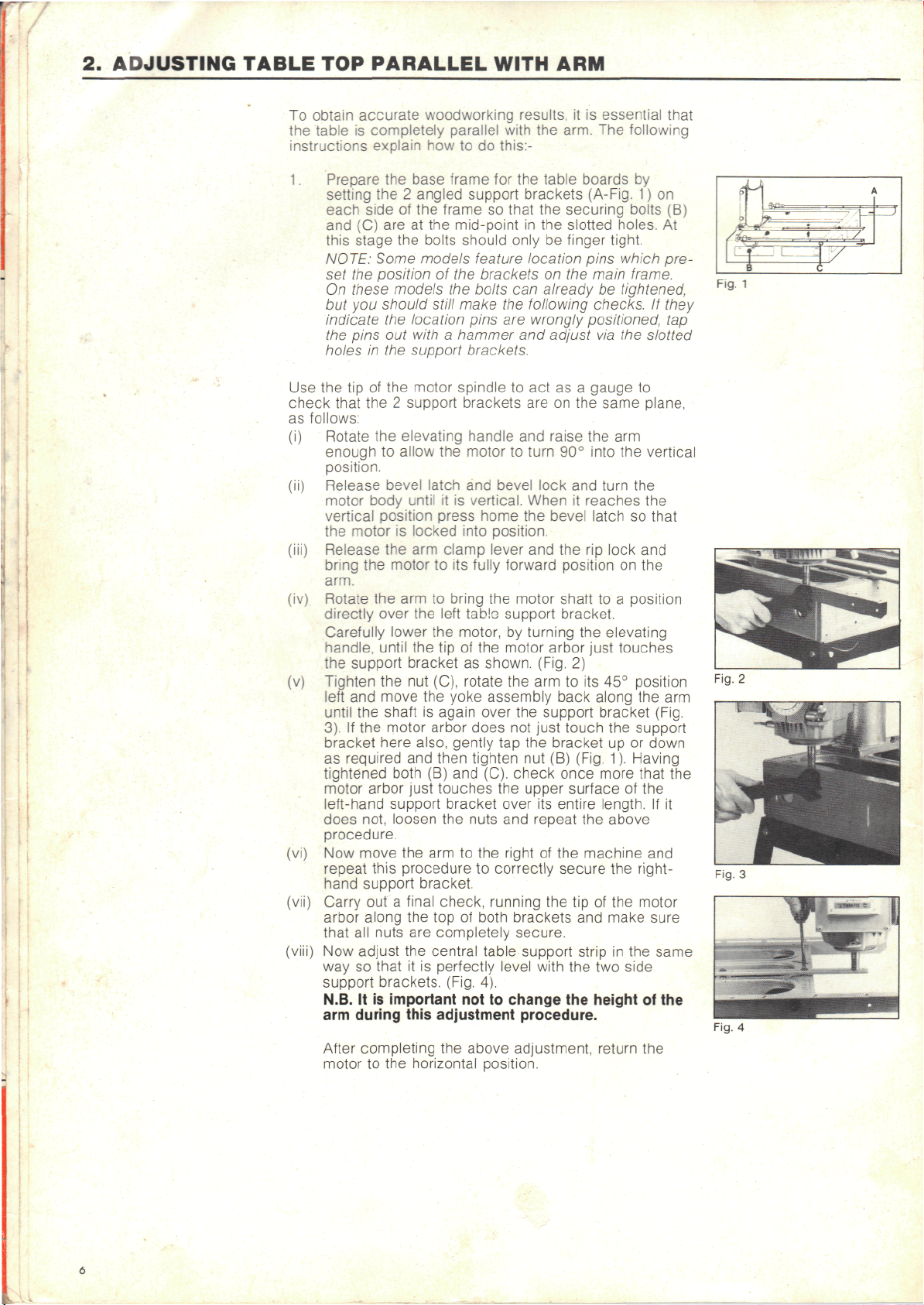
1.
Prepare
PARALLEL WITH
is
completely parallel with
how to do
the
setting
each side
and (C) are at the
this
stage
NOTE: Some
set
the
On
these
but you
indicate
the
pins
holes
base frame
the 2
angled
of the
the
bolts should only
models
position
models
should
the
out
in the
still make
location
with a hammer
support brackets.
frame
mid-point
of the
the
this:-
for the
support
so
that
feature
brackets
bolts
can
the
pins
are
brackets
in the
location
and
ARM
it is
the
arm.
table boards
the
on the
already
following
wrongly
(A-Fig.
securing bolts
slotted holes.
be
finger
pins which
checks.
positioned:
adjust
essential that
The
following
by
1)
on
(B)
tight.
main frame.
be
via the
At
pre-
tightened,
If
they
tap
slotted
Fig.
1
Use the tip of the
check that
as
follows:
Rotate
(i)
enough
position.
Release bevel latch
motor
vertical position press home
the
motor
Release
bring
the
arm.
(iv)
Rotate
directly over
Carefully
handle,
the
support bracket
(v)
Tighten
left
and
until
the
3). If the
bracket here also, gently
as
required
tightened both
motor
left-hand support bracket over
does
not,
procedure.
Now
move
repeat this
hand support bracket.
(vii)
Carry
arbor
along
that
all
Now
adjust
way
so
support
N.B.
It is
arm
during this adjustment
After
completing
motor
motor spindle
the 2
support brackets
the
elevating handle
to
allow
the
body
until
it is
is
locked into position.
the arm
motor
the arm to
lower
until
the nut
move
shaft
motor arbor does
arbor just touches
out a
nuts
that
brackets. (Fig.
important
to the
clamp
to its
bring
the
left
the
the tip of the
(C),
the
yoke assembly back along
is
again over
and
then tighten
(B) and
loosen
the
the arm to the
procedure
final check, running
the top of
are
completely secure.
the
central table support strip
it is
perfectly level with
the
horizontal position.
to act as a
are on the
and
motor
to
turn
and
bevel lock
vertical. When
fully
tablo
motor,
as
rotate
nuts
to
not to
above adjustment, return
the
lever
and the rip
forward position
the
motor
support bracket.
by
turning
motor arbor just touches
shown. (Fig.
the arm to its 45°
the
support bracket
not
just touch
tap the
nut (B)
(C).
check
the
upper surface
its
and
repeat
right
of the
correctly
both brackets
4).
the tip of the
change
procedure.
gauge
same plane,
raise
the arm
90°
into
and
turn
it
reaches
bevel latch
lock
shaft
to a
the
elevating
2)
(Fig.
once
the
machine
and
the two
the
height
the
up or
more that
above
the
make sure
in the
bracket
entire length.
secure
to
the
vertical
the
the
so
and
on the
position
position
the arm
support
down
1).
Having
of the
and
right motor
side
of the
the
that
(Fig.
the
If it
same
Fig.
Fig.
2
4
Page 7
3.
ASSEMBLY
OF
WORKTABLE
Note:
(i)
Secure
Note:
(ii)
Mount
(iii)
You can now
(iv)
Mount
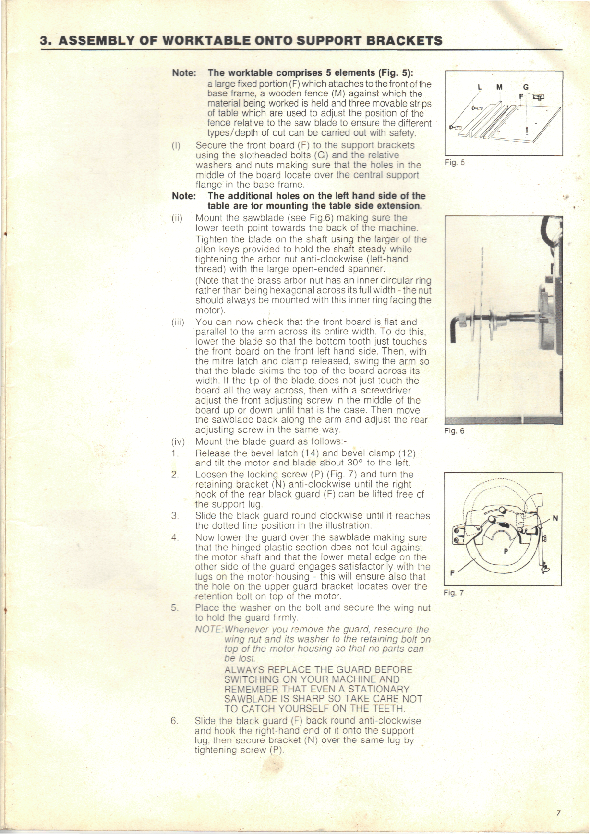
1.
Release
2.
Loosen
3.
Slide
4.
Now
6.
Slide
ONTO
The
worktable comprises 5 elements (Fig.
a
large fixed
base
frame, a wooden fence
material being worked
of
table which
fence
types/depth
using
washers
middle
flange
The
lower
Tighten
alien keys provided
tightening
thread)
(Note
rather
should always
motor).
parallel
lower
the
the
that
width.
board
adjust
board
the
adjusting
and
retaining
hook
the
the
that
the
other
lugs
the
retention bolt
Place
to
NOTE:Whenever
and
lug,
tightening
the
the
of the
in the
additional holes
table
are for
the
teeth point towards
the
with
that
than being hexagonal across
to the arm
the
front
mitre latch
the
blade skims
If the tip of the
all the way
the
up or
sawblade back along
the
tilt
the
the
of the
support lug.
the
dotted line position
lower
the
hinged plastic section does
motor shaft
side
on the
hole
the
hold
the
wing
top of the
be
ALWAYS
SWITCHING
REMEMBER
SAWBLADE
TO
the
hook
then
portion
are
relative
front board
slotheaded bolts
and
nuts making sure that
board locate over
base frame.
sawblade (see
blade
the
the
the
blade
board
front adjusting screw
down until that
screw
blade guard
the
bevel latch
motor
locking screw
bracket
rear
black guard round clockwise until
the
of the
motor housing - this will ensure also that
on the
on top of the
washer
guard
nut and its
lost.
CATCH YOURSELF
black
the
right-hand
secure bracket
screw (P).
used
to the saw
of cut can be
mounting
on the
to
arbor
nut
large open-ended spanner.
brass arbor
be
mounted with this inner ring facing
check that
across
so
that
on the
and
clamp released, swing
the top of the
across, then with a screwdriver
in the
and
(N)
anti-clockwise until
black guard
guard over
and
that
guard engages satisfactorily with
upper guard bracket locates over
on the
firmly.
you
motor
REPLACE
ON
THAT EVEN A STATIONARY
IS
guard
SUPPORT
(F)
which attaches
(M)
is
held
and
to
adjust
blade
carried
(F) to the
(G) and the
on the
the
table side extension.
Fig.6)
the
back
shaft
hold
the
front
blade,
same way.
as
blade about
in
remove
washer
housing
SHARP
(F)
using
the
anti-clockwise (left-hand
(14)
the
YOUR MACHINE
end of it
shaft steady
nut has an
the
front board
its
entire
bottom tooth just touches
left
hand side. Then, with
does
is the
the arm and
follows:-
and
(P)
(Fig.
(F) can be
the
illustration.
the
sawblade making sure
lower metal edge
motor.
bolt
and
the
to the
so
THE
SO
ON THE
back round anti-clockwise
(N)
over
BRACKETS
to
the
against which
three movable strips
the
position
to
ensure
support
the
left
hand side
making sure
of the
its
width.
board across
not
in the
case. Then move
bevel clamp (12)
30° to the
7) and
secure
guard,
that
GUARD BEFORE
TAKE CARE
onto
the
the
out
with safety.
brackets
relative
the
holes
central support
machine.
the
larger
inner circular ring
full
width
is
To do
the arm so
just
touch
middle
adjust
turn
the
lifted
not
foul
the
resecure
retaining bolt
no
parts
AND
TEETH.
the
support
same
5):
front
of the
different
in the
of the
the
of the
while
- the nut
flat
and
of the
the
left.
the
right
free
it
reaches
against
on the
wing
NOT
lug by
of
the
this,
its
the
rear
of
the
the
nut
the
can
the
the
on
Fig.
Fig.
Fig.
f
5
-
i
«t
'
I
6
7
Page 8
(v)
Position
according
cut to be
Note: Never
the
rear table boards
to the
carried
worktable
having
lift
to
your
material
out.
Powershop
or you
repeat
thickness
risk twisting
the
support bracket
adjustment procedure.
and the
and the
by
gripping
it and
fence (Fig.
type
therefore
of
8)
FENCE LOCATIONS
The
following
where
each
thickness/width
the
type
illustrations
fence
of cut
of
must
according
be to
material.
show
perform
to
4.
CHECKS
4.1
Checking
Crosscut
90° to the
AND
the
Travel
Fence
Mounting
Supplied with your Powershop
extension
satisfactorily.
The
extension
table
and it
(i)
Two
(ii)
The
ADJUSTMENTS
NOTE:
is
With
the
(18)
so
crosscarriage back
fence. Then,
so
that
table
in
You are now in a
line
at 90° to the
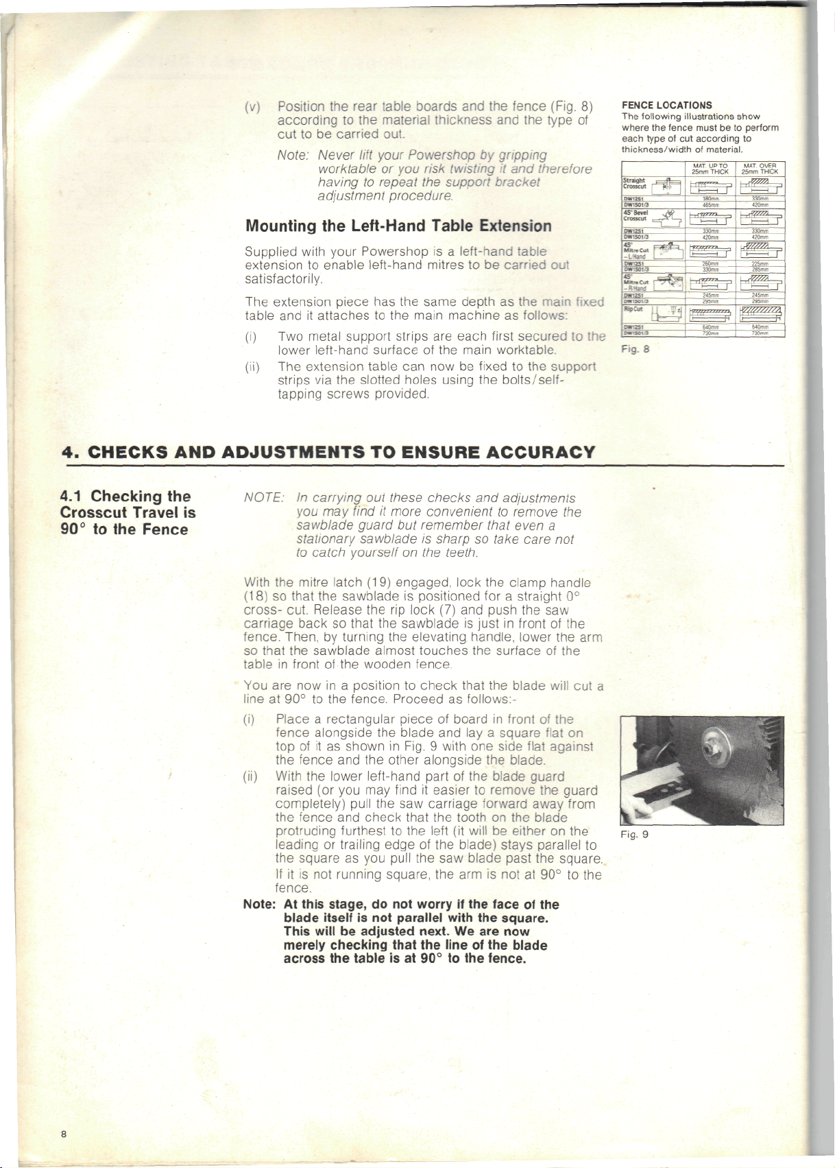
(i)
Place a rectangular piece
(ii)
With
Note:
At
the
Left-Hand
to
enable left-hand mitres
piece
attaches
has the
to the
main machine
metal support strips
lower
left-hand surface
extension table
strips
via the
slotted holes using
can now be
tapping screws provided.
TO
ENSURE ACCURACY
In
carrying
you may
sawblade guard
out
these
find
it
more convenient
but
stationary sawblade
to
catch
yourself
mitre latch
that
the
sawblade
cut. Release
so
that
by
turning
the
sawblade almost touches
front
of the
position
on the
(19)
engaged, lock
is
the rip
lock
the
sawblade
the
elevating handle, lower
wooden fence.
to
fence. Proceed
fence
alongside
top of it as
the
fence
the
lower left-hand part
raised
(or you may
completely) pull
the
fence
protruding furthest
leading
square
If
it is not
or
the
the
shown
and the
blade
in
Fig. 9 with
other alongside
find
the saw
and
check that
to the
trailing edge
as you
pull
the saw
running square,
fence.
this stage,
blade itself
This
will
do not
is not
be
parallel with
adjusted next.
worry
merely checking that
across
the
table
is at 90° to the
Table
same depth
are
of the
checks
remember that even
is
Extension
is a
left-hand
to be
as the
each
first
main worktable.
fixed
the
and
to
sharp
so
take care
table
carried
out
main
as
follows:
secured
to the
to the
support
bolts/self-
adjustments
remove
the
a
not
teeth.
the
clamp handle
positioned
(7) and
is
for a
push
just
straight
the saw
in
front
0°
of the
the arm
the
check that
as
follows:-
of
board
and lay a
one
of the
it
easier
to
surface
the
in
square
side
the
blade guard
remove
of the
blade will
front
of the
flat
flat
blade,
the
on
against
guard
carriage forward away from
the
tooth
left
(it
will
be
of the
blade) stays parallel
blade past
on the
blade
either
the
on the
square.
the arm is not at 90° to the
if the
face
the
of the
square.
We are now
the
line
of the
blade
fence.
fixed
cut a
to
Fig.
Fig.
8
9
Page 9

Fig.
10
To
Adjust
(i)
With
slacken
(ii)
Loosen
shown
(ill)
Release
the
arm
required, loosen
either
needs
the
right
If
the
move
left
and
flanges a little
latch
blade
overtighten
will
be too
(iv)
Once
retighten
Fig.
(v)
Adjust
registers
the
Crosscut
the
mitre latch engaged
the
mitre clamp.
the
lock nuts
in
Fig.
10.
the
mitre latch
needs
to
side
to go to the
of the arm and
opposite
to the
tighten
and
relative
satisfied
the
and
of the arm
is the
right, loosen
the
at a
clamp
and
to the
the
adjusting flanges
stiff
to
operate
that
lock nuts
10).
the
pointer
0° in
this
Travel
on
each
and
move
to
give
tighten
(Fig.
left,
loosen
tighten
case,
the
flange
time
the
on the
position.
on the
and
check
fence
with a square.
easily.
crosscut travel
on
each side
mitre scale
in the 0°
side
of the
depending
the
the
11)
and the arm
re-engage
the
true
adjusting
if the
front
the
adusting
the
flange
adjusting
right.
crosscut travel
or the
of the arm (as in
so
position.
arm.
on
which
90°
crosscut
flanges
of the arm
flange
on the
needs
flange
Adjust
the
mitre
Do not
mitre
is
accurate,
that
it
on the
the
latch
as
way
on
on
left.
to
of the
Fig.
11
4.2. Checking
Saw
Blade
to
the Arm
is
Tracks.
the
Parallel
This check
position,
run
"dog fashion" (Fig.
adjusted
set of the
would
being
To
Check
(i)
Place a square
To
Adjust
The
illustration
yoke
with yoke
to
the
(i)
Firstly,
(ii)
Then,
(iii)
Having adjusted
(iv)
Now
is to
the
blade
in
this way.
blade (distance across
also tend
cut.
with
the
crosscut
lock)
parallel
is
assembly.
yoke
movement
nut
locating slide
release
(J)
until
therefore
all
in
carriage
surface
clamp
is
the
carriage
the
If
the
accurate
sawblade just
position
check that
to the
necessary.
(Fig.
(17)
is
by the
grasp yoke
(H)
which increases
if the
the
(Fig.
13/13a)
the
blade
also parallel
nuts.
this
way,
forward.
of the
release
and
facing
the
the
slide
bar and the
backwards until
fence.
blade
fence,
parallel
ensure that,
runs true across
it
to
cause scorch marks
against
the
square.
13)
The
precise alignment
made
locking nuts (J).
left
or
bar (K) and
blade
yoke
clamp
and
is in
the
release
table
the rip
then rotate
fence
is
completely flat, across
this
will
in the
12).
If the
blade
will produce
the
fence
in
(lock
shows
possible
right,
is
Raise
confirm
rip
front
it in
left
in
still
fact parallel
blade parallel
the rip
by
locating
and
yoke clamp. Then push
cutting.
that position
hand face
If it is not
the
by
both hands
if
there
the
nylon
not
parallel
(10)
turn
yoke slightly
to the arm
lock
the saw
turning
the
yoke
lock
the
that
straight
the
a cut
the
of the
components
collar
is
friction between
and
the
slide
it
into
blade
the saw
90°
table
is
tips
on the
as in
of the
parallel,
of
and
movement tighten
block
loosen
to the
tracks. Then
to the arm
and
blade just above
elevating handle.
bar and the
90° so
that
is
cross-
and
incorrectly
wider than
of the
teeth).
timber
Fig. 9 and,
fence
with
blade
adjustment
of the
rollerhead
(I)
which
check
(L).
to the
square.
the
to
left
square
pull
the saw
that
position
resting against
its
face against
will
cut
does
not
the
It
in the 90°
the rip
is
(8)
is
fixed
it for
the rip
lock nuts
or
right
and
tighten
tracks
the
yoke
the
blade
with
the saw
perform
Fig.
Fig.
Fig.
12
13
133
Page 10

4.3
Checking
Blade
to
Fig.
is
Table
14
the
Perpendicular
If
by any
the
and
blade parallel
For
accurate woodworking,
sawblade cuts a precise
chance
fence then return
repeat
the
the
above adjustment procedure (making
to arm
90°
blade
does
it to the 0°
tracks).
it is
vertical
not lie
cross-cut position
also necessary that
line
flat against
when
intended
the
to
do so.
To
Check
With
the arm in the
latches/Clamp handles engaged, place a steel square with
one
edge
and the
(make sure
blade
then completely flat against
also
To
(i)
Remove bevel pointer disc
(iv)
(v)
Replace
on the
other edge against
the
and
rests against
not at
right angles (90°)
Adjust
screws
Tilt
the
Firmly
NOTE:It
(B) in
Loosen
the
motor
square.
retighten
screw
you do so, be
before replacing
cross-cut position
worktable parallel
square passes between
Fig.
the two
left
may be
(M)
the
bevel pointer disc.
the
left
the
inner face).
the
square,
to the
15
outside
or
right
the
alien
necessary
slightly before
(A) by
and
re-engage
alien
until
screw(s)
to
sure
to
the
bevel pointer disc.
secure
and all
to the
fence (Fig.
face
of the
the
If the
it
follows
worktable.
removing
the
screws
the
blade
L.
loosen
the
motor
it
sawblade
teeth
blade
bevel
(Fig.
16).
is
the
centre
will
again
14)
of the
is not
that
the two
latch.
flat
against
alien
tilt.
firmly
it is
If
Fig.
Fig.
15
16
4.4
Adjusting
Roller
Head
to Arm
10
Bearings
Tracks.
In
most cases
necessary
Radial
However,
the
adjustment
tracks
The
(Fig.
shafts
to
Arm
Saw.
in
time
which
roller head
17).
Two of
(Q) and the
(R).
If
there
is
arm
proceed
(i)
Pull
(ii) Remove
lateral movement between
tracks, (and
as
follows:
the
tracks
and
assembly
With
the rip
with
an
18).
Having slackened this screw, also loosen
13mm
lock
Then
release
the
access hole
rotate
the
sufficiently
that
all 3
moved backwards
find
it
difficult
you
may
so
that
tracks.
Once satisfied that
retighten
alien screw
NOTE:
The top and
bearings
over
their
should move freely
the
above adjustments will
enable accurate
it is
possible that play might develop
of the
will
yoke assembly forward
the rip
alien
bearings rotate
find
you can see the 3
the
should
roller
cause inaccuracy.
is
suspended
these
are
third
you
will
lock
it in
scale
by
withdrawing
scale pointer removed,
key to the
nut (J)
the rip
in the
eccentric bearing
in
contact with
to
feel when
it
easier
13mm
and
replace
be in
entire length
sawing
head
bearings
by
three special bearings
mounted
is
mounted
be
able
to
position with
pointer
the two
locking
immediately beneath
lock
and
underside
(R)
the arm
as the
and
forwards along
the
if you
remove
bearings rotating
the
lock
nut and
the
ripscale pointer.
bottom edges
contact
and the
but
without side-play.
be all
that
with
your
DeWalt
to the arm
on
straight bearing
on an
eccentric shaft
the
bearings
feel
it, if
to the end of the arm
the rip
on the
right
Phillips screws.
you
screw
as
with
an
alien
of the
slightly until
track
yoke assembly
adjustment
the Arm
adjustment
then
the
of all
with
the arm
roller
head assembly
and the
there
is)
lock.
of the
have access
shown. (Fig.
the
it.
(Fig. 19).
key via
yoke (Fig.
it is
to
ensure
the
arm.
is
correct,
end-cap
in the
is
correct,
horizontal
three
tracks
are
in
yoke
20)
is
If you
Fig.
Fig.
Fig.
Fig.
17
18
19
20
Page 11

Note:
From
time
build-up
of
bearings - especially
accuracy
and
necessary
follows:
(i)
Remove
(ii)
The
the
the arm
yoke assembly will
arm.
With a clean,
their
entire length
(Fig.
21).
With a vacuum cleaner
on the 3
can be
(v)
Remount
replace
screws
bearings
used
the
the arm end
are
to
time,
you may
dust
in the arm
after
ease
clear
of
this
to
end-cap.
dry
cloth wipe
to
remove
and
of the
if
necessary
yoke assembly
cap, making sure
tightly
secured.
find
that
tracks
or on the
ripping.
operation,
dust.
then
the arm
all
cloth,
it
This
can be
come
out at the end of
tracks
dust
and
clean
yoke assembly.
to
remove
compacted
in the arm
there
To
maintain
will
grease
off all
White
tracks
all
is a
be
done
along
dust
spirit
dust.
and
retaining
as
4.5
Adjusting Base
to
Column
CAUTION: Never attempt
these bearings
to
lubricate
or the arm
cause premature wear
The
following adjustment
will
also normally
unnecessary unless your Powershop
frequently
If.
after,
cut
position
side,
arm
following adjustment
(i)
Loosen
(ii)
Turn
from site
the
mitre latch
and the
or
up-and-down,
caused
by the
the
alien
screws
rear)
and
an
alien key.
the
down.
If
adjust
by
the
correct
to
site.
is
engaged
mitre clamp
movement
column moving
is
necessary:
lock nuts
on the
(U in
left
then slacken
elevating handle
base
is
seen
to be
unscrewing
fit has
the two
been achieved. Avoid binding
in the 0°
is
secured, there
at the
in its
Fig.
of the
the
inner brass screws with
to
move
slack around
nuts W (Fig. 22a) until
overtightening.
If
the
base
is too
unscrewing nuts
tight around
(X) and
the
tightening nuts
correct fit.
(iii)
Retighten
back
them
CAUTION:
of the
in
position.
After
again
to
the
the
brass screws against
column
carrying
the
and set the
out
this adjustment, check
straight cross-cut travel
fence
- and
adjust
the
tracks,
and
inaccuracy.
surface
as
of
this
be
has
been moved
straight cross-
is
front
end of the
base,
22) on the 2
still
the
brass
base (looking from
the
column
the
up and
column,
column, adjust
(W) for
the key on the
lock nuts
to
hold
is at 90°
if
necessary.
can
the
by
by
Fig.
22
Fig.
22a
Page 12

5. THE
5.1
Mounting
SAWBLADE
Blade Guard
the
GUARD
See
instruction
3.
(iv)
5.2
Adjusting
Blade Guard
the
— For Rip
(i)
Loosen
(ii)
Loosen
Important:
—
For
Neither
needed
adjusted
Cuts:
knife bracket
(C)
machine's worktable.
from
loosening
within
lower
bottom
timber (i.e. when
(L)
the
blade).
into
should
the 2
is
approximately
the
the
the
the
of the
are
positioned
wood before
Once
contact
be at the
It is
kickback fingers
they
throw
Note that
kickback fingers onto
be
be
It
is
correct position when
timber
Cross-Cutting:
the
riving knife
for
cross -cuts,
up out of the
knobs
(B)
blade must
the
screws
bracket
knob
bracket
bracket just
the
with
essential
prevent
the
loosened
angled
also important
binding
(H)
down until
10mm
(G) and
slots).
(Q) on the
(D)
the
tips
at
about 1/8"
you
start
anti-kickback fingers
the
surface
angle indicated.
for
the
timber back towards
the
alien
to
for
bevel-ripping.
nor the
so
way.
(Fig.
23) and
the tip of the
(%")
The
distance
be
between
sliding
back
until
the
central spring
touches
of all
anti-kickback
below
to
feed
of the
safe rip-cutting that
are
correctly positioned
tendency
screw mounting
allow
on the
make sure that they
its
the
to use the
ripping
blade.
anti-kickback fingers
slide
from
the
of the
1-3mm.
the
knife
of the
guard
the
surface
the
the
timber
have
timber,
of the
support bracket
kickback fingers
blade
the
riving knife
to
the
riving
riving
surface
riving
(adjust
left
on the
fingers
surface
into
come
they
the
to
operator.
the
prevent
are
both
knife
of
the
knife
by
or
right
and
of the
of
the
anti-
•
anti-
can
to
in its
the
are
";
5.3
Removing
Blade
5.4
Guard
Removing
Sawblade
12
the
the
Follow
the
mounting procedure
The
arbor
turn
(i)
Fit the
(ii)
Fit the
(iii)
Holding
(iv)
(iv)
Hold
nut has a
it
clockwise
large alien
the
motorshaft
(Note
that
rather
should always
motor).
as
near
large
nut
will loosen.
Remove
noting
you
If
the nut is
following method:
Lock
rip
lock.
Fit
the
Position a striking block
with
clockwise until
block
CAUTION:
HAND
AND
MEANS
the
than being hexagonal across
large open-ended spanner onto
parallel
the
spanner clockwise with
the
the
order
remount
the
roller
large spanner
the
spanner
some
force, turning
and the nut
TAKE CARE
ON THE
NEVER
OF
(3.(iv))
left-hand thread,
to
remove
to
brass
be
alien
blade
the
difficult
head
the end of the
EXPOSED TEETH
TRY TO JAM THE
HOLDING
it
from
key
supplied into
hold
the
shaft steady.
arbor
nut has an
mounted with this inner ring facing
to the
alien
key
firmly with
and all
of
assembly
blade.
on the
loosens.
to
loosen
in
position
to the
of
the
NOT TO
THE
flanges
nut, while
in
reverse order.
so it is
the
motor
the
its
key as
arbor
wood
blade/motor shaft anti-
SHAFT STATIONARY
possible.
one
hand,
the
other hand
on the
and
positioning
in
this way,
on the arm
nut
as
shown
at the
spanner strikes
CATCH
OF THE
MOTOR
necessary
shaft.
front
inner
circular
full width
the
arbor
turn
motor shaft
use the
with
only.
in
same time,
YOUR
BLADE
FAN AS A
to
end of
ring
- the nut
the
nut
the
and the
for
when
the
Fig.
24.
the
Rotate
spanner
anti-clockwise
Fig.
24
Page 13

6.
MAKING A TRIAL
6.1
Wiring
up to the
Mains
CUT
Having
now
Note:
completed
time
to
If,
when
saw
carriage
would
pieces
arm
tracks
assembly.
tracks
the
above adjustment
make a straight cross-cut
you
were
setting
travel
was not as
expect,
of
that
probably
polystyrene
or to the 3
packing
bearings
With a clean,
and the
bearings
Single-Phase 240v Models
Connect a standard
to
the
cable attached
illustration. Make sure that
outer sheath
the
plug.
Plug
in and
of the
switch
13
amp
to the
rubber-covered
machine
the
cable
cable securely before fixing
on at the
mains socket.
in a
up
your
smooth
means there
stuck
dry
cloth
to
eliminate
as
clamp
procedure,
piece
machine,
as you
either
on the
wipe
yoke
both
this.
earthed
shown
is
holding
in the
the cap to
it is
of
timber.
the
are
to the
the
. ;-•
plug
the
6.2
Making
the Cut
Three-Phase
415v
Models
Three-phase machines should
mains
by a
suitably qualified electrician.
(i)
With
(ii)
Release
the
handle
straight
so
that
mitre
so
that
0°
cross- cut.
the rip
the
sawblade
lock
the
sawblade
lock
engaged,
and
is
correct position depending
(See
Fig. 25).
(iii)
Now,
(iv)
Gripping
by
turning
so
that
the
the
table. Place
of
the
of
the
sawblade almost touches
fence.
the
switch handle, press
push- button switch
the
elevating handle, lower
the
piece
same hand.
(v)
Once
the
sawblade
has
(after a short speed build-up
rotate
the
cut a
elevating handle
shallow groove
or
table.
(vi)
Now
pull
cuts a vertical slot
the
piece
to
the
(vii)
Now
switch
side
of the
With
a set
timber
further adjustment
the saw
of
column.
square check that
is a
timber,
off the
switch.
true
90° in
blade
in the
and
machine
each plane.
is
necessary
appropriate instruction.
Note:
The
3
very
useful
(1)
It
"locks
to
be
maintained — useful when ripping (obviously)
but
also advantageous
(2)
There
removing power from
control
switch
on
your
feautures:
on" so
that thumb pressure does
for
is
motor overload protection built into
the
overheating.
(3)
It has a
of
actuated before
"no-volt release"
power
the
switch
the
has to be
motor
be
wired directly into
lock
the arm
is
positioned
push
behind
on the
the saw
the
carriage back
fence
material thickness
the
of
timber against
the
with
reached
of 2 or 3
to
allow
kerf
in the
slowly towards
wooden fence
then
push
by
the cut in
right-hand side
the
thumb
maximum speed
seconds)
the
blade
surface
you so
and
the
carriage
pressing
your piece
If it is
and
refer
Powershop
incorporates
left-hand operators.
motor
in the
event
so
that
if
there
deliberately
will
run.
clamp
for a
in its
the arm
surface
the
of the
to
of the
that
through
the
left-hand
not, then
back
to the
not
need
it
of it
is a
removal
re-
the
of
front
just
it
back
of
FENCE
LOCATIONS
The
following
where
the
45
Mitre
45
Mitre
-R Hi
LHai
type
ut
25
fence must
of cut
each
thickness/width
Fig.
illustrations
be to
according
of
material.
show
perform
to
V--
25*Tv-
: .
THICK
~
13
Page 14

7.
SCALE
ADJUSTMENTS
7.1 Rip
Scale
The rip
When
column, that
material must
When
operator,
material
The
adjustable
1.
2.
3.
4.
5.
Note:
scale
is
located
the
motor
is
positioned with
is
called
be fed
the
motor
that
is
must
be fed
pointer
Place a board
the
Position
towards
assembly along
forward
Loosen
move
lines
scale. Tighten
Now
rip" position without moving
The
position
position
for
indicating
as
follows:
fence
in its
the
the
edge
the two
the
pointer until
up
with
remove
"in-rip" pointer should
on the
of the
the
fence when "in-ripping".
It is
generally good practice
cut
with a tape rather than relying solely
scale, although
complete
differing
first
widths (i.e. +5mm
cutting
the
through
is
positioned with
called
the
from
the
of
known
"rip" position (See Fig. 25).
motor
in its
front
of the
the arm
of the
material.
screws
the
known width
the two
the
board
upper
blade here indicates
the
confidence
width).
on the
scale
right side
the
"in-rip"
left
ripping width
machine)
on the
the
screws.
and
scale
position
the
blade from right
"out-rip" position
width
"out-rip" position
until
when
the
to
right.
(say
and
the
blade just
pointer assembly
edge
of the
of the
place
the
the
yoke assembly.
now
line
(adjust
to
can be
making
or
-7mm relative
of the
radial arm.
blade facing
and
your
blade facing
and the
on the
about
board
up
if
necessary).
the
check
used with
scale
24cm)
(blade
move
the
touches
"out-rip"
on the
motor
in its
with
the
ideal
location
the
on the
several
width
the
to
left.
the
is
against
yoke
and
pointer
lower
"in-
zero
The
of
cuts
at
to the
the
7.2
7.3
Bevel
Mitre
Scale
Scale
The
bevel scale
beneath
for a vertical cut,
scale.
disc,
then retighten
The
the
can be
been correctly positioned
cross-cut.
right.
provide accurate
the
To
adjust, loosen
and
move
mitre scale
elevating
adjusted
The
mitre latch engages with machined locations
is
located
switch handle. When
the
pointer
the
disc
the
screws.
is
located
handle.
The
On top of the arm is a
to
align with
scale
is
then marked
45°—0°—45°
on the
the
until
on the top of the arm
and
front
of the
the
blade
should
screws retaining
the
the
be at
pointer points
'0'when
clamped
for a
0°-50°
positioning.
zero
motor'
is
positioned
on the
the
pointer
to
'0'
and
beneath
pointer
the arm has
to
straight
left
and
which
to
14
Page 15

8.
CLAMP HANDLE ADJUSTMENTS
(i)
The
(ii)
(iii)
(a)
(b)
(c)
(d)
Having removed
(e)
Mitre
Clamp
adjusted
the
the
the nut on the
surrounding
half a turn
when
elevating
The
same
to do so
The
involved.
If
you
movement
adjust
Remove
Remove
tracks.
While
downwards with a screwdriver
so
turn
large
underneath moves
lever,
within
the
NOTE:
arm, take
the arm
Replace
if its
elvating handle.
clamp handle
it is
Bevel
way as in (i)
adjustment
find
as
levering
that
the
screwdriver
check that
the
yoke assembly
While
secure position means
other
casting.
and
pull
again
handle.
Clamp
with
the
that
the
to
satisfactorily
follows:
the arm
the
complete yoke assembly
the
it
will
pass over
central bolt
movement
the
the
opportunity
tracks with a clean
the arm
handle
and
retightened
motor
of the
end-cap.
so
the
the
yoke assembly
end-cap.
(18)
may
need
it
In
such a case,
push
it
end
You can
the
clamp handle back
handle (12)
above
yoke clamp
Yoke Clamp
spring steel locking flange
in the top of the
that
on one
small screwdriver used
clamp does lock satisfactorily
arc
to the
into
protrudes from
then tighten
it
does
may be
but you may
in its
vertical position.
has
clamp
(as
the lug on the
the
locking flange
segment past
available
armtracks.
is
to
clean
dry
cloth.
hinders
simply
the
casting
not
obstruct
adjusted
find
is a
little
insufficient
the
yoke securely,
from
shown
yoke casting,
yoke with
and
then return
removed
the
bearings
to be
slacken
so
its
up the nut
out so
it
easier
more
the arm
in
Fig.
the
lug.
as a
from
use of
that
that
the
in
the.
26)
a
the
and
Fig.
26
9.
HINTS
ON
GENERAL CARE
1.
Keep
2.
When
3.
Keep
4.
From time
5.
Never attempt
6.
When carrying your Powershop resist
OF
the
machine
build-up
machine could
sure
before
amount
be
dry
particulary
clean
may
remove
tracks.
remove
If
you
be
cap
bearings
premature
to
frame instead.
twisting
your
of
dust
in the
be
changing
that
the
securing.
the
worktable clear
of
cut
could cause inaccuracy.
cloth
to
the arm
find
it
the
White
compacted dust.
remove
sure
to
securely.
or the arm
lift
it by
it and
machine.
or
blade
dust between
to
time wipe
eliminate dust build-up which
after
a lot of rip
tracks
easier
yoke assembly completely from
spirit
the
tighten
to
lubricate
wear
and
gripping
If you
therefore
YOUR POWERSHOP
clean
for
efficient operation.
immediate vicinity
hazardous
remounting
and
and the 3
to
detach
can be
yoke assembly, when replacing
the
retaining screws
tracks,
inaccuracy.
the
worktable — grip
lift
and
lead
to
the
sawblade, make
adjacent flanges
of
sawdust. Just a small
the
fence
and the
the arm
it by the
reducing
tracks with a clean,
cutting
the arm end cap and
used
the
as
or
sanding.
yoke bearings,
if
necessary
in the arm end
surface
this
of
can
cause
the
worktable
the
accuracy
the
A
of the
inaccuracy.
are
clean
material
can
ensue
To
you
the
to
these
temptation
base
you
risk
of
to
it
15
Page 16

10.
The
numbers
10.1
Arm
10.2
Blade
THE
VARIOUS
in
bracki
Rotation
Height
OPERATING
refer
to
those
in the
''Controls"
The
radial
arm
Release
(19).
Then swing
angle. Then lock
The
calibrated mitre scale
handle
and
'0'
straight cross-cut position.
The
mitre latch
0° and 45°
clamp handle also
other,
position.
The
Radial Arm,
raised
or
top
of the
moves
the
rotates
the
mitre clamp handle (18)
indicates
(15)
positions
lowered
column. Each complete rotation
blade
ADJUSTMENTS
illustrations
to
right
or
left
for
the arm (2)
the
clamp
the
angle
is
only used
but
adopt
to
secure
and
hence also
by
turning
up or
down
right
handle(18).
(1)
is
the arm in
the
by
and the
or
left
just below
of the arm
to
locate
the
habit
the Saw
elevating
about 3mm.
OF
BASIC
on
page
mitre cuts.
mitre latch
to the
required
the
elevating
relative
the arm in the
of
using
this,
as
blade,
handle
of the
2
to the
the
well
as any
can be
(6)
handle
MACHINE
mitre
10.3 Yoke
Rotation
10.4
Blade
11.
MAKING
11.1
Cross
(Fig.
27)
Assembly
Tilting
THE
Cut
Changing from cross-cut
seconds.
Release
then
automatically
always secure
Turn
the
Tilt
clamp released,
popular
BASIC
(iii)
(v)
the rip
swing
the
table. Release bevel clamp (12)
the
motor
0°. 45° and 90°
slide
the
at the
elevating handle
to the
bar (4) and the
yoke
to
four
the
yoke clamp also
desired
the
latch will automatically locate
CUTS
Set
the
radial
registered
elevating
tighten
Turn
the
position
the
thickness
To
cut
right through
necessary
table top.
on
the
motor before
table surface
when lowering continues. Switch
Place
material
the
fence, keeping your thumb
from
the
Switch
fence
and
will
find that
assembly forward - rather
speed
of
tend
to
After
completing
return
the
fence.
arm at
as 0° on the
handle.
the arm
behind
path
on
jam.
clamp handle.
elevating handle
the
of the
to cut a
If
such a groove
so
on
the
motor
and
across
you do not
travel
in the cut
sawblade
to the rip
right
or
90°
to
angle
angle positions.
right angles
Lock
the
fence
material being
the
shallow groove
the
that
it
will
worktable
sawblade will take.
draw
the
material
the
cut, switch
to its
position takes
yoke clamp (10)
left.
The
positions,
to
raise
the
sawblade
and
on the
mitre
lower
is not
cut
into
and
and
the
sawblade
to
to
will need
to the
latch
correct
to be
already
off the
hold
make
pull
off and
mitre scale beneath
to
in its
material
blade actually
need
you
otherwise
rest position
only
well
scale.
in the
the
into
it is
also
slightly
against
well
cut.
limit
will
the
and
to
above
(1'
With
and
for
25)
in the
switch
the
away
the
You
the
yoke locks
but
remember
maximise accuracy.
bevel
latch
bevel
fence.
in
position
the
blade
position
cut
(See Fig.
sawn
or
kerf
there,
touches
the
table
motor.
firmly
fingers
through
the
the
motor
to
the
blade
carefully
behind
Fig.
27
16
Page 17

11.2
(Fig.
11.3
(Fig.
Mitre
28)
Bevel
30)
Cut
Cut
Release
Swing
mitre scale.
The
the
mitre
intermediate angles, lock
clamp handle only.
The
the
Proceed
crosscutting. Remember that
slightly
material
different
When cutting a left-hand mitre (Fig. 29),
(v)
probably require a different
needed when cutting
angle.
moveable table strips into position behind
hand table extension.
Set
Rotate
above
Release
Tilt
bevel scale.
The
0°,
handle
required,
motor rigidly
Place
thickness
Then, with
carefully
it
just cuts into
be
the arm
the arm to the
mitre
latch
0°
straight cross-cut position
positions, together with
fence should
thickness
to
into
and
slot
You
arm as for 0°
the
elevating handle
the
surface
the
the
motor
bevel latch enables
45° and 90°
as a
the
the
fence
of
the
lower
drawn through
clamp
required angle shown
should
of the
make
the
table surface
each
cut in the
will also need
bevel
in the
secondary lock.
bevel
in
position.
material (See Fig. 25).
sawblade still behind
the
the
be
be
placed
material (See Fig. 25).
the cut in the
mitre angle
fence.
the
cross cut.
of the
clamp
yoke
positions,
clamp
in
position depending
blade
table surface.
the
fence
handle
used
the
the arm in
in
you
to cut
fence position from that
corresponding right-hand
to
slide
to
table.
handle
to the
you to
but use the
If any
on its own
with
the
and
and the
to
position
same
cut
raise
and the
required
accurately locate
into
mitre
latch.
on the
locate
and at the 45°
clamp
will need
will require
the
motor running until
The
the arm at
handle.
position
way as for
right through
fence
the
other angle
will hold
on the
the
blade
the
with
depending
to cut
you
will
and
the
blade well
bevel latch.
angle
bevel clamp
fence,
can
material.
At
arm
your
a
left-
on the
the
is
the
then
on
Fig.
Fig.
Fig.
28
29
30
11.4 Ripping
(Fig.
31)
Set
the arm as for
Pull
the
yoke assembly
Release
clamp.
Revolve
wide
narrower
accordingly (Note: Photo actually shows machine
bevel-ripping).
Make sure
(v)
appropriate
once
Position
desired width
right
position
Now,
section 5.2. Then turn
dust
Then, following
(viii)
arm, switch
firmly
quickly
When
IX
machine
the rip
the
panels (Fig.
cuts (Fig. 32), positioning
the
yoke slot
again
to
the
side
of the
with
adjust
is not
thrown into your face.
against
into
the
you
have finished
by
cross cut.
out to the end of the
locating slide
motor
90° to the
31)
or 90° to the
slide
bar
lock
yoke assembly along
of rip
the rip
the
on the
the
pressing
and the
the
cut. using
arm,
and
lock.
sawblade guard
the
the
instruction label
machine and, with
fence,
revolving
the
bar and the
right
locates positively
yoke
clamp
in
position.
the rip
lock
the
dust ejection spout
feed
it
evenly
saw
blade.
the
cut, switch
main switch again.
for
left
the
is
the arm for the
scale
yoke assembly
as
described
on the top of the
arm.
yoke
out- ripping
for
in-ripping
fence
in the
tightened
on the
in
so
the
material
and not too
off the
on
in
that
Fig.
Fig.
31
32
17
Page 18

IMPORTANT:
1. Use a
2.
Before switching
3.
After
notched "push-stick" (Fig.
and see
wood through
down
keeping
from
ripping,
anti-kickback
positioned
completed,
has
the
clean,
11.
drawing
at the
your
the
blade.
make sure
the
ripping operation
collected
yoke assembly's bearings
follow
in
Fig.
the
same time, thereby
hands
on the
fingers
for
safe
you may
in the arm
the
instructions
41) to
blade
and
at a
safe distance
motor
the
riving
are
correctly
operation.
find that sawdust
tracks
hold
knife
has
on
33
feed
it
for
been
and on
- to
page
the
and
Fig.
33
11.5 Bevel
(Fig.
32)
11.6
Compound
(Fig.
35)
11.7
Coving/
Hollowing
Ripping
Mitre
(Fig.
36)
(i)
Set the
above,
(ii)
Then
described
(iii)
Using
arm for the
(iv)
Angle
flat
riving
(v)
Then
The
compound
mitre cut.
(i) Set the
(ii)
Release
(iii) Swing
relock
(iv) • Draw
Note:
You may
By
tilting
can
produce
sawing systems.
being cut. Having tilted
yoke
beneath
ripping.
variety
The
optional
examples
utilised.
machine
rotate
the
yoke assembly into
for
ripping
on the
fence
the
By
of
widths
of how
the rip
the
knife.
proceed
the arm
the arm
the saw
changing
lock
correct
anti-kickback fingers
material
with
mitre
cut is a
machine
the arm
into
clamp handle.
across
find
to
motor with
many shapes
it
hold
it
In
Fig.
the
arm,
the
and
pitches
Powershop Handbook gives further
this feature
in the
bevel cross-cut position
so
ripping.
and the
clamp
rotated
is fed
machine
the rip
that they
34) and
of a
as for
the
in the
with
through
can be
above.
locate
the
yoke assembly
ripping
being
the cut as for
in the
clamp handle
the
advisable
firmly while cutting.
the
36, a
the
the
angle combinations,
width.
cut
(Fig.
combination
bevel position.
required mitre position then
the
material
to
blade
rotating
not
possible
shallow concave
blade
and
material
of
channel
of
your
as
position
on the
will
be
lower
the
bevel
and a
mitre
latch.
mitre cuts.
material
conventional
profile
the
an
work,
motor
as for
infinite
made.
can be
to the
you
is
as
Fig.
35
11.8
(Fig.
18
Dishing
37)
By
releasing
latch
with
rotating
shallow hollow
to
the
position
before tilting
procedure
It
is
end of the
flexing
its
mounting.
an
blade
table.
and the
until
necessary
motor while cutting progresses
and
pressure being
the
bevel clamp
appropriately
can
then
in the
surface
The
blade
elevating handle wound down
the
rotating blade again
the
required depth
to
hold both
and
shaped piece
be
tilted
through
of a
is
then returned
the
blade guard
placed
disengaging
piece
and
has
on the
the
of
wood,
an arc to cut a
of
wood
to the 0°
repeating this
been reached.
to
blade guard
bevel
the
clamped
upright
half a turn
and the
avoid undue
other
and
Fig.
Fig.
36
37
Page 19

11.9
Circle
(Fig.
38)
12.
OPERATION
Cutting
ACCESSORIES
Although a circular
to
make straight
straightforward
standard
Cramp a false table
as
thick
woodscrew
chosen
underside
formed,
of
proposed
arm by
on the pin in a
each
waste
OF THE
Even
sawblade,
any
The
dimension
your
as the
aid,
and
the
wood,
half a turn. Then using both hands rotate
revolution
is cut
MACHINE WITH OPTIONAL ATTACHMENTS
in its
other type
range
Powershop into a complete workshop.
saw is
cuts,
on
circular
as a pin and
of the
circular
standard form with
the
of
to
your radial
saw
table
and
then
wood, from
then
fit to the
and
lock
cut.
clockwise direction against
lower
away,
and the
Powershop
of
sawing system.
optional attachments, however,
your woodworking potential. They
normally thought
cutting
blade.
to the
main one,
itself
in
place
screw this part
saw the
which
pin.
the
carriage
Hold
the
the arm by
circular piece
is
already more versatile than
perfect circles
arm saw
of the
head off. Make a hole
the
Lower
at a
wood firmly
half a turn
the
basic general purpose
of as
only able
is
also quite
using only
or
substitute a strip
fence.
way
circle
the
tangent
Use a
into
the
is to be
blade just clear
to the
and
lower
the
the
blade.
until
all the
is
formed.
add a
will
the
in the
wood
After
further
turn
the
Fig.
38
AND
12.1
Shaping/
Moulding
You
will
find
the
optional
advantageous, particularly when cutting hardwoods
man-made
'sharpening
blades.
Note:
Adding
decorative
DeWalt Shaping Head
used
and
groove joints.
illustrated
The
DeWalt Shaping/Moulding Head
motor arbor
(i)
Remove
(ii) Mount
(iii)
Now put the
(iv)
Fit the
materials.
and
have a much longer
Never
for
flanges
Shaping Head) onto
the
into position with
special
Block
the
Block
use
blades larger than 250mm diameter
an
imperial
and is
therefore
Before
mounting
accessories,
mains
power supply.
that
professional
edge
is
cutting
recessed centre facing outwards
same extent beyond
round grooves
in the
list
as
follows:
the saw
and saw
the
special back flange(s) (supplied with
Shaping Head
box
spanner (Fig. 40).
required pair
carefully setting them
itself.
TCT saw
TCT
blades require less frequent
10"
blade
too
large.
or
disconnect your Powershop from
quick
The
at the
changing
finish
and
attachment
range
back
blade guard, arbor
blade.
the
the
special clamping
of
blades prove
life
than ordinary steel
measures 254mm diameter
any
attachments
to
your work with a clean
easy with
and for
of
cutter profiles available
of
motor arbor.
on the
shaping knives
the
the
39).
drawer,
is
mounted
nut,
motor
optional
It can
and
blade
shaft
and
then lock
nut,
in the
of the
(Fig.
this booklet.
so
they both protrude
outside edge
on the
using
and
also
tongue
the
with
Head
—
or
the
be
is
the
or
to
it
Fig.
Fig.
39
40
19
Page 20

(v)
Now,
(vi)
Before operating
tilt
the
scale
so
that
the
special Shaping Head
position depending
intend
to use
Position
the
the
the
amount
fence.
table will depend
the
position
Shaping Head needs
obstructed
options:
motor
to its 90°
the
Shaping
the
machine
on the
(Fig. 39).
yoke assembly
of
knife profile required
The
height
of the
the
moulding
on the
height
to be in a
by the
fence,
you
position
Head
you
guard
depth
on the
is
horizontal.
should
and
adjust
of
knife
on the arm so
extends
Shaping
is to
of
your
trace
Head
on it. If the
position
have
the
bevel
now
its
profile
that only
in
above
material
otherwise
following
mount
you
front
of
the
and
two
Fig.
42
EITHER
OR
A. Cut
B.
away a section
to
provide sufficient space
and
guard
to
Position
thickness
two
as the
fence position,
"Note:-
If you
you
new
(viii)
Having locked
arm
with
it
just clears
evenly
moulding
choose option
replace
fence
for
the
the rip
the
along
the
block.
the
modified fence with a complete
normal sawing operations.
yoke assembly into position
lock
and
material, feed
fence from
cutters. Maintain positive pressure.
IMPORTANT:Use a piece
pusher (Fig.
hand keeps a safe distance from
knives.
(viii)
An
infinite variety
Shaping Head
presented
to the
NOTE:Figs.
Quality Shaping
the
more intense, larger
of
profiles
by
varying
wood (Fig. 42).
39/40
feature
Head
shaping/rebating applications.
available,
however, a general-duty
head (Fig. 43), which
for
slow-feed,
a
similarly wide range
fine-finish
of the
existing
for the
protrude through it*.
pieces
of
timber
(of the
fence provided)
one on
A, it is
positioned
of
41) to
the
the
either side
recommended that
the
guard
the
material firmly
the
right into
the
waste wood
make sure your
can be cut
height
DeWalt
which
using
of the
Premium
is
designed
profile
There
shaping
is
perfectly satisfactory
applications
of
compatible
fence
block
same
in the
of the
on the
so
shaper
as a
the
the
cutter
for
is
also
and has
cutters.
that
and
Fig.
Fig.
PUSHER
SPRING
41
43
12.2 Rebating
Fig.
45
20
(i)
With
(ii)
If
the
straight-edged knives
Shaping/Moulding
rebating,
wider rebates
should
in the
same
are
be
fitted (see separate instructions)
guard used should
Head.
The
way,
Note
in
ensuring
operation,
is the
same
the use of
the
as
home-made wooden springs
timber
Head
can
way as
required, then a Dado Head
be
that intended
using
with
the
the
is
held firmly against
while cutting progresses (see Fig.
(iii)
Again
the
motor
can be
tilted
cutting.
(iv)
If the
joint,
rebating
then
the
is
necessary
Dado Head
for a
can be
cross-cut position with repeated passes
across
the
material until
has
been obtained (Fig. 45).
the
mounted,
also
described
be
the
used
above.
for
narrow
but the
for the
Dado
Head
Shaping
in
this
Shaping Head (Fig. 44).
to
help
the
fence
41).
for
bevelled
mortice
used
required
in the
of the
width
rebate
and
tenon
normal
of
rebate
Head
Fig.
44
Page 21

'
12.3
Ploughing/
Grooving
Flat
grourf«U>acUr>read
V-
Note:
In
this upright position, however,
that
the
Dado
Head
is
sawblade guard (with
removed)
With
repeated passes,
grooves adequately. When a wider groove
Dado Head
cutting rebates
one
pass.
Set
at an
grooves
rebates
horizontal).
There
your
of
The
resharpenable again
Dado-ing.
than
Mount
(i)
(ii)
(iii)
(iv)
(v)
(vi)
for
(rip
are two
machine (Fig. 47).
the two but is
premium-quality
the
first.
the
Remove
Mount
with
Mount
the
necessary
the
two
required.
Secure
sawblade arbor
Mount
the
riving
from
Then,
Head into position
It
may be
on
top of the
sufficiently
of
material.
and
no/the
the
is
more appropriate (Fig. 46).
and
housings, making a wide deep
angle
the
Dado Head
staircases (mitre
position),
types
of
perfectly adequate
Dado
It is
Dado Head
the
the
narrower
the
cutter
the
the
within
by
and
therefore correspondingly more expensive
as
the
sawblade
special
Dado
standard
knife
rotating
necessary
side
Head
number
sections
Dado
Head
nut
and its
the
guard (Fig. 48).
the
standard
depending
covered
the
Shaping
ordinary
and
optional
The
back
for the
position),
mortices
Dado
flat-ground type
Head
again
for
follows:
and its
spacer
towards
on the
of
chippers
to
obtain
on the
(left-hand
sawblade
support
elevating
depth
to
place a supplementary table
worktable
on the
by the
riving knife assembly
Head guard.
saw
blade
can be
long grooves
or
Head available
for
intermittent use.
has a
longer-life
relatively intensive
related flanges.
on the
the
motor,
shaft, having inserted
or
the
shaft with
thread).
guard, having removed
bracket completely
handle
of cut
to
raise
depth
of
it is
essential
standard
will
often
is
needed
It is
also ideal
used
tenons
is the
motor arbor
shims between
width
the
lower
required.
cut/thickness
to
make
and is
of cut
standard
the
the
work
a
cut in
(blade
cheaper
Dado
and
for
cut
for
the
Fig.
46
Premium
Fig.
47
ado
Head
12.4 Disc Sanding
Note:
If you are
positions,
the
If,
however,
the
sawing
adjusted
surface
through,
illustrated
The
basic machine
produces a clean
finishing.
difficult
used
ideal
The
(i)
Remove
(ii)
For
shape,
for
sanding cuts
for
large scale flat sanding.
disc sander mounts directly onto
Return
that
both
each
dado-ing
guard
direction
the
should
you are
of
and the
down
of the
when
in
Fig.
if
cut
jobs needing a final sanding
the two
the
sawblade guard
the
outer sawblade flange
the
inner
other.
only
anti-kickback
be
adjusted
dado-ing
material
anti-kickback
so
that
material
the
fingers
23.
properly adjusted with a sharp blade
that normally requires
optional sander attachments
at any
and
outer flanges
in the
feed
their
until
should
angle.
crosscut
fingers
tips
the
The
and the
on the
up out of the
in the rip
is the
same
fingers
are
wood
adopt
or
disc sander
the
spindle (Fig. 49).
blade
to the
are
or
position,
must
"e"
below
is fed
the
no
further
having
spindle
flat
mitre
back
way.
as for
be
angle
a
can be
is
itself,
so
against
of
the
Fig.
Fig.
48
49
21
Page 22

Fig.
Fig.
50
51
(iii)
Now
using
sawblade
angle required.
If
the
yoke assembly
position),
table.
If
the
material
firmly
locked
When using
50) you may
alongside
against
Always
disc,
material
In
most
However,
sanding
be
mounted
disc
When removing
necessary
alien
screw
the
the
Disc Sander onto
same angle adjustments
is
mounted, position
the
the
spindle and,
as
when
sanding
sanding operation requires movement
(as in a
make sure
operation requires
past
in
the
both hands, while
on the arm by the rip
the
Disc Sander
find
it to
the
use the
otherwise
support your material
disc.
downward (right-hand)
you
the
disc,
it
easier
will
bevel
material
the
movement
then
the
the
lock.
as a
to
clamp a faJse
find
it
or
straight
is
held firmly
material
yoke
assembly
sanding
difficult
of the
must
higher
side
to
hold
steady.
sanding
is
just
key
when
(Fig. 51),
to
supplied
positions a guard
using
the
and
clear
the
hold
Shaping
adjusted
of the
Disc Sander
the
motor shaft
with
the
disc
up so
underside
the
machine.
is
for
horizontal
Head
that
of the
you
will
steady
unnecessary.
guard
the
a
disc
at the
of the
crosscut
on the
be
is
table
table
up
of the
the
should
sanding
guard.
find
it
with
the
held
(Fig.
Fig.
52
12.5 Drum Sanding
Fig.
55
12.6 Sabre Sawing
The
optional Drum Sander enables
of
contours
otherwise
The
Drum Sander screws directly onto
with
the
the
disc sander above (Fig. 54).
The
height
in
the
No
guard
When
advantageous
strips,
be
moved around
Always
and
irregular shapes (Figs.
can
only
be
sanded
sawblade flanges mounted
and
angle
of the
Drum Sander
same
way
as
with other
is
necessary.
using
the
Drum Sander vertically
to
remove
the
fence
thereby allowing plenty
the
Sander.
feed your material against
Drum Sander.
By
mounting
motor
machine into a radial sabre
(i)
First
(Fig.
on
special lugs
(ii)
Finally,
attachment
You
on
cases
spindle
mount
56) and
the
shaft with
can
the
requirements
the
the
optional Sabre
in
place
of the
the
special back spacer onto
then stabilise
the
in the
motor housing.
use the
standard
on the
shaft.
then position
best position will
sawblade.
- or
steady struts
the
of the
Sander above:-
—
remove
spacers 20mm thick
forwards)
and low
slide
the
just behind
enough
across
table fence
and
the
so
that
the
upper surface
and
then position
front table section (Fig.
the
easy,
accurate
52/1
by
hand.
the
in the
can be
attachments
motor
same
(Fig.
),
wht
spindle,
way as for
altered
I
sanding
you may find it
and/or
of
space
the
Saw
jigsawing
the
arbor
sabre
nut to
the
for
your
rotation
attachment
you can
machine.
the
saw
locating
secure
rear
table
material
of the
on the
turn
your
spindle
attachment
on the
the
sabre sawblade depending
job.
In
most (Fig.
be as
with
substitute
it
the
57)
the
Drum
with wooden
blade (teeth
58)
shoe
of the
attachment
of the
material being cut.
will
to
Fig.
Fig.
54
56
Fig.
57
Page 23

12.7 Routing
Fig.
61
Fig.
62
J
\
Fig.
65
The
mounting
enabling
broadens
woodworking
There
is a
One is
suitable
or
any
other
most
ELU
your
Powershop.
Since
the
Powershop
completely
The
mounting procedure
(i)
Remove
the
(ii) Position
Powershop motor
the
machine's motor housing (Fig. 59).
correctly,
also locate over
the top of the
secured with
(iii)
j043mm
The
be
which
ELU
The
support
router
diameter bars
positioned
The
models
bolted
mounted through
rod.
Note: Whichever
(iv)
You are now in a
choice into
either hold
whatever
need,
cutter
attachment). This
when
Alternatively,
Powershop table
machine's yoke assembly,
the
of one of the
you to fit a
the
with your machine.
choice
with
Routers (MOF 96/31
Router itself
motor,
from
motor shaft.
bracket
Collar Routers
router's
removed (Fig.
is
Router Bracket
bracket
bars (Fig. 62). These
base
larger diameter bars
as
to the
be
the
be
position with
normally
and
(as you
you are
same
portable Router
scope
enormously
of two
for the
a.043mm
the
the
blade guard, blade
the
router bracket over
behind
the
normal
then secured
for ELU
in
on the
shown (Fig.
held securely
ends
centred
the
the
angle
feed
way as
mounting brackets:-
Black & Decker
will
you can
hole
motor housing, where
the
rear
you can
be
power supply.
is as
shaft,
the
in the
the
standard guard retaining
wing
control/plunge
60) to
Routers comes with
place
of the
are
used
bracket
of the
the
base
Elu
of the
on tne
the
lock
the
position
router
router
is
required
the
material against
would with
is the
routing
and
when sawing (Fig. 66).
optional Router Brackets,
collar.
disconnect
nut
in the
router
bars
and
in a
an
clamp
move
to
your
for
accurate,
The
/98/77)
operating
follows:-
and all
the end of the
carefully locating
lugs
on the end of the
upper
arm of the
supplied,
expose
for the
64)
router base
in the
bars
locking screws which would
router side fence
method
irregular shape.
its
Yoke (Fig.
are
side fence rods.
MOF96
as
shown (Fig. 63).
fit the
MOF31
with
the
in
place
is
used,
bracket
and the
and
to fit the
begin working.
fixed position (Fig. 65),
to
provide
the
Drum Sander
the
the
router,
to
perform
Powershop,
decorative
DN66
other
the
inserted through
of
material
Woodworker
will
enable
to be
secured
and not the
Powershop
flanges from
the
lugs
In
lining these
bracket
bolt
it can be
assembly
43mm collar,
and are
matt finish
and the
of the
the
by the
router must also
held firmly
cutter
the
the
operating
via the
the
firmly
must
61).
two
pairs
The-small
/98/77
other
side fence
router must
nuts
in the
in
position.
of
your
You can
shape
rotation
to use
to the
operation
to
up
on
bar
on
at
you
of the
of
will
of
the
in
Fig.
Fig.
60
63
Fig.
66
•J
^-
\
J
Note: Routing with
basic sawing operations
the
other optional attachments,
covered
The
It
is
out of
in
another optional DeWalt accessory:
DeWalt Powershop Handbook.
packed full
your machine.
the
Powershop,
of
hints
as
with
all
and
woodworking with
is
on how to get the
other
extensively
most
Fig.
64
23
Page 24

12.8 Drilling/Boring
Fig.
69
At
the
rear
location
end of the
to
accept
the
enabling your machine
The
capacity
It
is
particularly useful
68),
and for
It
also enables many
Powershop,
and
arbors, sanding
Note:
For
of the
drilling a series
such
complete
before
fitting
chuck
as
drill
and
safety,
the
drill
motor
shaft,
there
is a
threaded
optional Drill Chuck (Fig. 67),
to be
used
as a
radial
available
in
preparing material
of
is
identical holes (Fig. 69).
accessories
bits,
boring
bits,
10mm
to be
drilling
or
%".
for
dowels (Fig.
used with your
grinding
wheels
polishing discs, flexible drive, etc.
always remove
the
Sawblade
Drill Chuck.
unit.
Fig.
67
12.9 Special Mitre
Fences
Fig.
70
12.10 Automatic
Safety
Return
12.11 Legstands
Fig.
73
Special adjustable mitre fences
accessory
facility
fences
and
angles left
excess
In
picture
against
next
the
matching
If the
fences
fence
the
middle
This
the
rest
is
particularly
passes
the two
the
other
There
to
extend
of the
Powershop (Fig. 70).
fit in
of
place
cuts
or
45°.
right,
allow
framing,
the
piece
left-
would
45°
project
requires various mitre angles,
avoids
each
time,
between
accessory
position behind
useful when
of the
blade.
holes
in the top
end of the
are two
different types
and
speed-up
of the
to be
hand
be
angle
having
since
(Fig.
standard wooden fence (Fig.
made from 0-90°, including acute
as
well
as the
for
example,
fence
for the
laid against
and
guarantee a neat
to
make
the
the
sawblade always passes down
pair
of
72)
ensures that
the
fence after each cross-cut.
the
The
return mechanism
right-hand side
cable attached
of
DW1251
Cat.
No.
DA850
as
follows:
The
stand
(i) The 4
one end
fits
the
comprises
legs
are the
only.
DW1251
12
strips
long angle pieces with holes
The
other ends
orange rubber feet.
(ii)
Of the
remaining 8 pieces,
the top of the
which
is the
same size
legs
to
form
as the
DW1251.
(iii)
The
remaining
third
up
(iv)
Do not
tighten
Legstand assembly
located
(v)
Once
you
together,
you
do not
probably
on
the
floor.
and
bolt
in the
two
pairs
from
the
feet.
any of the
until
relevant holes.
have been able
the
Powershop
have
an
to lay the
assistant,
Powershop down with
You can
it via the
holes provided.
then
Powershop plus Legstand
upright.
are
available
the
The
as an
angle-cutting
non-identical pair
more normal angles
you
would
set
material
first
angle
and
the
right
hand side
use of
a new cut in the
then
to cut
90°
corner.
these
standard
special fences.
the
blade returns
project involves repeated
is
of the
to the
mounted
column, with
yoke assembly.
Legstand.
(Fig.
73) and is
of
angle iron.
assembled
at
of the
legs
accept
two
pairs
fit
together
the top of the
base frame
fit to the
nuts
all
to
can be
lay the
can
legs
at
and
bolts
have been properly
tighten
the
secured
the
best
way is
Legstand down
The
then
complete
be
carefully stood
Legstand
about
in the
stand
to the
of the
its
column
at
one
'
top.
71)
in
the
to
It
via
the
of
If
Fig.
Fig.
Fig.
68
71
72
24
Page 25

DW1501/3
Cat.
No.
DA2588 fits these models
as
follows (Fig. 74):
The
stand
consists
orange feet
(i)
The
(ii)
Attach a pair
and 4
base lengths
off
straight
near
their ends.
from
the 2
Fig.
74).
each
end of the
galvanised
at
holes points
The
plastic feet
being those pieces which
which
is
where they attach
Powershop.
Note:
If
your Legstand
the top of
the
hole arrangement
different
correctly
of 8
lengths
of
brackets,
are
each
those 2 pieces
end and
The end
with
to the
can now be
base lengths.
of
legs
to
each base
are
features
them,
rather than only
from that
the
for the
holes "point towards
and
should
box-section
be
steel,
which
have 2 pairs
the
longer
front
of the
of
distance
stand
attached
section,
angled
to the
at one
frame
of the
legs with 3 holes
2,
for the
front
note that
leg is
back leg. When fitted
each
assembled
4
are cut
holes
(See
to
the
legs
end.
in
other":
Fig.
74
Having attached a pair
join
up the
(v)
horizontal
The
facilitate
Lay
on
the
the
should
each
the
The 4
two
TYPE
The
legs
cross members using
bolts should
fixing
the
Powershop down with
floor
longer base outriggers pointing upwards.
now be
leg
with
Powershop mainframe.
galvanised brackets supplied
types:
A
above drawings show
which
frame,
(vi)
(Vii)
Once
The
the
sure that
legs have been bolted
all
Powershop complete with Legstand
carefully
stood upright
column,
(viii)
If the
Powershop
corrected
rotating
on the
by
them
floor
of
legs
resulting
and lay the
two leg
be
left
of the
quite loose
Legstand
Legstand down similarly with
able
to
line
the
corresponding holes
up
how
are
then bolted
nuts
and
'rocks'
removing
so
that
is
adjusted accordingly.
to the
bolts
are
by
lifting
on its
the
relevant plastic feet
the
thickness
to
each base length,
sections with
the
bolts provided.
at
to the
its
the
this
Powershop.
rear column resting
holes
in the top of
in the
may be one of
TYPE
B
they attach
Powershop main
to the
frame make
secured tightly.
can now be
it at the top of its
feet
this
can be
of
plastic resting
the
stage
You
side
to the
to
of
and
25
Page 26

OPTIONAL
ATTACHMENTS & ACCESSORIES
SAWBLADES
Application
Correct blade selection
Blades
are
made
sharpening
best
materials—needing
and
than steel blades.
DADO
HEADS
Basically
flat-ground
an
dado
applications.
quality dados with
precision
and
extra 24mm
NOTE: Dado Heads
However,
SHAPING
The
3-cutter general-duty shaping head
fine-finish applications
can be
if
Dado
used vertically with std. sawblade guard after removing
Head
ACCESSORIES
and has a
is
for
important T.C.T.
hardwoods
less
lasting
much
adjustable-width
is
satisfactory
For
intense
longer
cutting
is
used
use the
HSS
tips provide exceptional DA293
life.
They also have
depth.
horizontally
~
is
wide variety
designed
of
Cat.
No.
DA1100(DA81)
and
man-
DA1110
DA1020
longer
DA1040
DA1041
DA1042
saw
blade
the
for
most DA2020
DA2000
premium DA2021
an
DA153
DA154
for
wide
for
slow-feed,
rebating,
shaping
DA3701-DA3721
compatible cutters.
Description
Replacement
Crosscut
(DA94)
T.C.T.
T.C.T.
T.C.T.
Plastic-cutting
Blade—for
Blade—gen.
Blade—for
Rat-ground
Prem.
quality
Prem.
quafty
Replacement
Replacement
Replacement
riving
ki
head
guard
DA693
of
3) for
d
comb,
steel
blade
H.S.S.
dado.
dado.
dado.
spacer
spacer
shim
its
must
DA3600
steel blade (44T)
(68T)
(1.4mm x 200T)
ripping
(24T)
purpose
veneered
Width
6-20mm. 0 152mm
Width
6-12mm. 0 200mm.
Width
10-19.5mm. 0 200mm.
for
dado
for
dado
set for
support
be
DA2020
bracket
mounted.
(40T)
board
heads
heads
utters
(GOT)
(sets
(Knives
are
25.4mm
wide
and
The
shaping head
2-cutter premium quality shaping head
larger
profile shaping
a
wide range
o-'eJo
37003
37004
37011
37012
(Knives
37005
37013
are
of
QJ
37006
37014
30mm
and
rebating applications
compatible cutters.
Lj-a
37007
37016
wide
37006
37017
and
If
the
DA3000
DA3050
DA158
case
not
Shaping
o.o
37009
37018
37019
shaping
head
and add
box
spanner
available separately).
heads
37010
set is not
must
is 0
125mm.)
is for the
and has
head
is 0 90mm.)
appropriate
cutters
as and
also required. (DA3000 carrying
not be
used with-out guard
DA693 mounted correctly.
SANDING & SABRE
^S>>s.
Precision
evi|j|.v
s
\
the
\%ft, \ contour, internal
Qkfe^J
^_^*^
,fC^f%\
^j&t^?'
sander
face/end sanding.
Sabre
based man-made material
SAW
finish
as a
Saw
ACCESSORIES
sanding
of a
job.
and
makes
Use the
edge
all the
drum sander
sanding.
stationary circular sander
cuts curves
in
wood
up to
NOTE: When used horizontally disc sander should
ROUTER
MOUNTING
For
/KT.^
vi/Ur
lighter-duty routing work,
Decker
with
BRACKETS
DN66
a 0
43mm collar,
woodworker,
can be
the
or any
y \ Powershop with this bracket.
rijJ
il
OTHER
1
Enables
securely
ATTACHMENTS & ACCESSORIES
These legstands provide
and
-;.;-.,
.g*~
operations.
For
For
angles
For
\~~~'\
i==4l
^=4^
jO^ a returns
// A 'must'
^><&=)V
make
the
more powerful
mounted
to the
Elu
Powershop.
the
necessary rigidity
convenient working height
precision
greater
are
boring
mitre
often
/drilling
capacity
required.
or
jobs
when
intense cross-cutting applications this spring-
the
blade
to
for
Powershop owners
the
most
rest position
of
their
machine's versatility.
more intense,
buy the
when
difference
Use
or for
or
wood-
10mrn
be
covered
Black
other
attached
routers
for
satisfactory
in
wood.
different
after
each cut.
who
really want
needed.
to
for
the
disc
thick.
&
to the
to
be
DA3600 Gen.
37003-37019
DA3000
DA3050
DA158
Prem.
Premium
Special
DA693 Guard
DA220
DA2073
DA231
DA230
DA2099
DA294
DA301
by
guard DA693.
DA2096
DA2097
DA850
DA2588
DA302
DA440
DA203
to
DA2090
duty
incl. 3 each
Additional
per
shapii g head/cutter
of
and
pack)
for
quality
plastic
case.
37004/8/10/12/16/17/18
special
spanner
quality
pair
of
37016
Box
spanner
(included
sander.
Drum
10
Disc
6
assorted
Sabre
for
when
sander
special
sander
saw
in
DA3000
shaping
sanding
- 0
sanding
incl.
Replacement
3
blades
for
DA2099
Router
mounting
collar
of 0
43mm.
Router
mounting
professional
MOF98.
routers
MOF31.
Legstandfor
Legstand
10mm
Special
drill
mitre
for
chucks
Automatic safety return.
Powershop
handbook
cutters
DA3712/14/17/19.
replacement
DA3
/DA3050.
shaping
head/cutter
ind. 2 each
shaping
rebating
cutters.
for
set).
heads
used
horizontally.
-0
63mm.
sheets
200mm.
discs
spacer
spacer
for DA
bracket
bracket
MOF96,
MOF77.
DW1251
DW1
50/3
& key
fences
cutters
of
cutters
and
head
DA3050
(and
dado
for
for
DA231
and 1
2099.
for
routers
for Elu
set in
(one
set in
complete
shaping
head/disc
DA220
blade
with
box,
with
head
a
NOTE:
The
details
of
Black & Decker reserves
26
this list
the
are
right
subject
to
revise
to
change.
For an
product specifications
accurate, up-to-date
and
prices
listing
at any
of
attachments
time without
and
notice.
accessories
available
and
prices,
please
ask
your DeWalt
stockist.
Page 27

©
DiWALT
WOODWORKING MACHINES
Black & Decker Professional Products Division.
Westpoint,
Telephone: (0753) 74277 Telex:
The
Grove, Slough, Berks,
SL1
1QQ.
84S317
Black & Decker
reserves
the
right
at
any
to
revise DeWalt
time without notice.
Offset
Litho Ltd., West
product
Drayton,
specifications
Middlesex,
bngland.
and
prices
 Loading...