

Page 1

DEWALT Industrial Tool Company, P.O. Box 158, 626 Hanover Pike, Hampstead, MD 21074 Printed in U.S.A. (APR97-CD-1) Form No. 383945
DW100-220 Copyright © 1997
383945/DW100-220 5/3/02 1:15 PM Page 2
Page 2

INSTRUCTION MANUAL
GUIDE D'UTILISATION
MANUAL DE INSTRUCCIONES
DW100-220
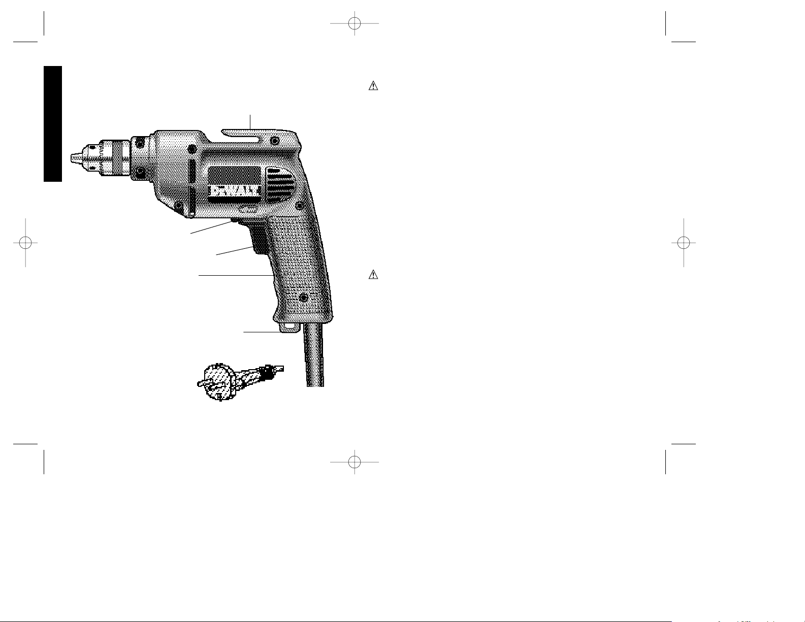
3/8" V .S.R. Drill
Perceuse de 10 mm (3/8 po) à régulateur de vitesse et inverseur de marche
Taladro V.V.R. de 10 mm (3/8")
INSTRUCTIVO DE OPERACIÓN, CENTROS DE SERVICIO Y PÓLIZA
DE GARANTÍA. ADVERTENCIA: LÉASE ESTE INSTRUCTIVO ANTES
DE USAR EL PRODUCTO.
383945/DW100-220 5/3/02 1:15 PM Page 3
Page 3
Important Safety Instructions
WARNING: When using electric tools, basic safety precautions
should always be followed to reduce risk of fire, electric shock, and
personal injury, including the following:
READ ALL INSTRUCTIONS
Double Insulation
Double insulated tools are constructed throughout with two separate
layers of electrical insulation or one double thickness of insulation
between you and the tool’s electrical system. Tools built with this
insulation system are not intended to be grounded. As a result, your
tool is equipped with a two prong plug which permits you to use
extension cords without concern for maintaining a ground
connection.
NOTE: Double insulation does not take the place of normal safety
precautions when operating this tool. The insulation system is for
added protection against injury resulting from a possible electrical
insulation failure within the tool.
CAUTION: WHEN SERVICING USE ONLY IDENTICAL
REPLACEMENT PARTS. Repair or replace damaged cords.
Safety Instructions For All Tools
• KEEP WORK AREA CLEAN. Cluttered areas and benches invite
injuries.
• CONSIDER WORK AREA ENVIRONMENT. Don’t expose power
tools to rain. Don’t use power tools in damp or wet locations. Keep
work area well lit. Do not use tool in presence of flammable liquids
or gases.
• GUARD AGAINST ELECTRIC SHOCK. Prevent body contact
with grounded surfaces. For example; pipes, radiators, ranges, and
refrigerator enclosures.
English
IF YOU HAVE ANY QUESTIONS OR COMMENTS ABOUT THIS
OR ANY D
EWALT TOOL, CALL US TOLL FREE AT:
1-800-4-DEWALT (1-800-433-9258)
REVERSING LEVER
TRIGGER SWITCH
LOCKING BUTTON
BELT CLIP
LANYARD RING
220 VOLT PLUG
383945/DW100-220 5/3/02 1:15 PM Page 4
Page 4

• KEEP CHILDREN AWAY. Do not let visitors contact tool or
extension cord. All visitors should be kept away from work area.
• STORE IDLE TOOLS. When not in use, tools should be stored in
dry, and high or locked-up place — out of reach of children.
• DON’T FORCE TOOL. It will do the job better and safer at the
rate for which it was intended.
• USE RIGHT TOOL. Don’t force small tool or attachment to do the
job of a heavy-duty tool. Don’t use tool for purpose not intended.
• DRESS PROPERLY. Do not wear loose clothing or jewelry. They
can be caught in moving parts. Rubber gloves and non-skid
footwear are recommended when working outdoors. Wear
protective hair covering to contain long hair.
• USE SAFETY GLASSES. Also use face or dust mask if operation
is dusty.
• DON’T ABUSE CORD. Never carry tool by cord or yank it to
disconnect from receptacle. Keep cord from heat, oil, and sharp
edges.
• SECURE WORK. Use clamps or a vise to hold work. It’s safer than
using your hand and it frees both hands to operate tool.
• DON’T OVERREACH. Keep proper footing and balance at all
times.
• MAINTAIN TOOLS WITH CARE. Keep tools sharp and clean for
better and safer performance. Follow instructions for lubricating
and changing accessories. Inspect tool cords periodically and if
damaged, have repaired by authorized service facility. Inspect
extension cords periodically and replace if damaged. Keep
handles dry, clean, and free from oil and grease.
• DISCONNECT OR LOCK OFF TOOLS when not in use, before
servicing, and when changing accessories, such as blades, bits,
cutters.
• REMOVE ADJUSTING KEYS AND WRENCHES. Form habit of
checking to see that keys and adjusting wrenches are removed
from tool before turning it on.
• AVOID UNINTENTIONAL STARTING. Don’t carry tool with finger
on switch. Be sure switch is off when plugging in.
• EXTENSION CORDS. Make sure your extension cord is in good
condition. When using an extension cord, be sure to use one
heavy enough to carry the current your product will draw. An
undersized cord will cause a drop in line voltage resulting in loss
of power and overheating. The following table shows the correct
size to use depending on cord length and nameplate ampere
rating. If in doubt, use the next heavier gage. The smaller the gage
number, the heavier the cord.
Minimum Gage for Cord Sets
Volts Total Length of Cord in Feet
120V 0-25 26-50 51-100 101-150
240V 0-50 51-100 101-200 201-300
Ampere Rating
More Not more AWG
Than Than
0-6 18161614
6 - 10 18 16 14 12
10-1216161412
12 - 16 14 12 Not Recommended
• OUTDOOR USE EXTENSION CORDS. When tool is used
outdoors, use only extension cords intended for use outdoors and
so marked.
• STAY ALERT. Watch what you are doing. Use common sense.
Do not operate tool when you are tired.
• CHECK DAMAGED PARTS. Before further use of the tool, a
guard or other part that is damaged should be carefully checked
to determine that it will operate properly and perform its intended
function. Check for alignment of moving parts, binding of moving
parts, breakage of parts, mounting, and any other conditions that
may affect its operation. A guard or other part that is damaged
should be properly repaired or replaced by an authorized service
center unless otherwise indicated elsewhere in this instruction
manual. Have defective switches replaced by authorized service
1
English
383945/DW100-220 5/3/02 1:15 PM Page 1
Page 5
2
center. Do not use tool if switch does not turn it on and off.
• CAUTION: When drilling or driving into walls, floors or wherever
live electrical wires may be encountered, DO NOT TOUCH ANY
METAL PARTS OF THE TOOL! Hold the tool only by insulated
grasping surfaces to prevent electric shock if you drill or drive into a
live wire.
SAVE THESE INSTRUCTIONS
Motor Brushes
DEWALT uses an advanced brush system which automatically stops
the drill when the brushes wear out. This prevents serious damage to
the motor.
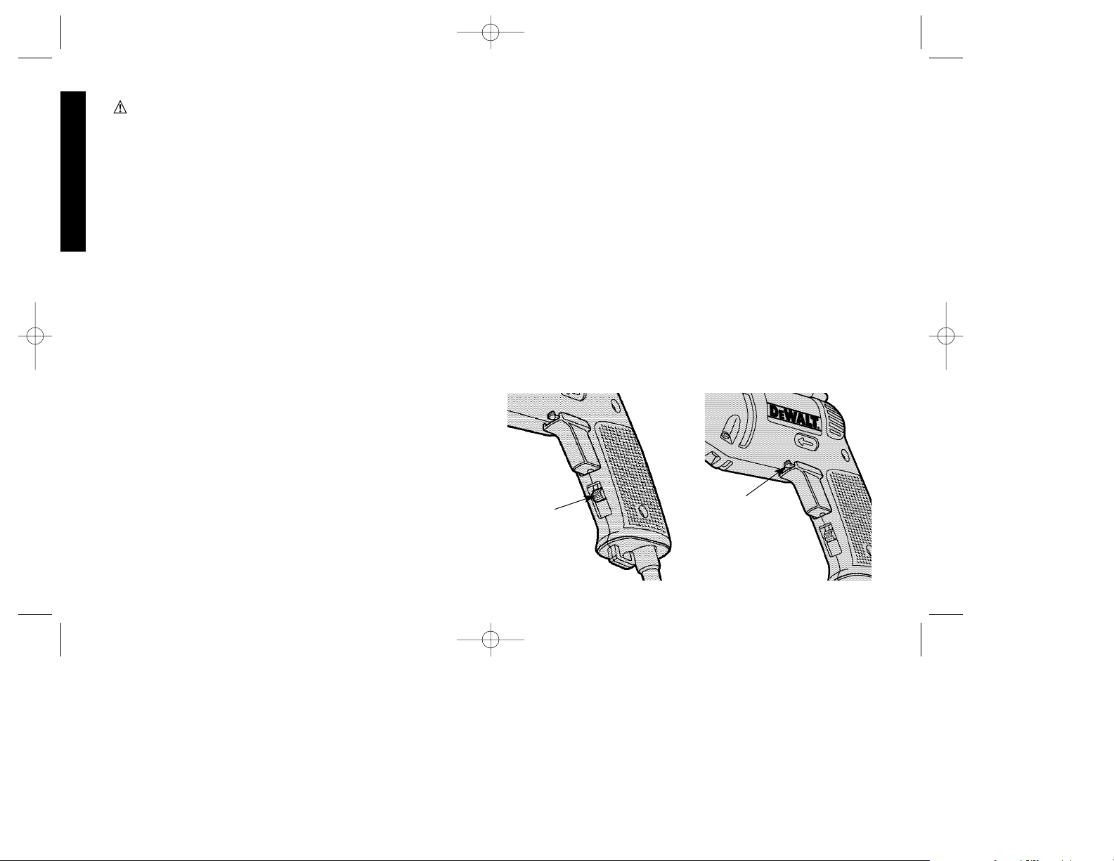
Switches
To start drill, depress trigger switch; to stop drill, release trigger. To
lock trigger in “ON” position for continuous operation, depress trigger
and push up locking button “A” Figure 1, then gently release trigger.
To release locking mechanism, depress trigger fully, then release it.
Before using the tool (each time) be sure that the locking button
release mechanism is working freely.
Do not lock the switch “ON” when drilling by hand so that you can
instantly release the trigger switch if the bit binds in the hole.
The locking button is for use only when the drill is mounted in a drill
press stand or otherwise held stationary.
Be sure to release the locking button before disconnecting the plug from the
power supply. Failure to do so will cause the tool to start immediately the
next time it is plugged in. Damage or injury could result.
THE VARIABLE SPEED TRIGGER SWITCHpermits speed control –
the farther the trigger is depressed, the higher the speed of the drill.
NOTE: Use lower speeds for starting holes without a center punch,
drilling in metal or plastics, driving screws or drilling ceramics. Higher
speeds are better for drilling wood and composition boards, and for
using abrasive and polishing accessories.
THE REVERSING LEVER is used for withdrawing bits from tight
holes and removing screws. It is located above the trigger switch
(Fig. 2). To reverse the motor, release the trigger switch FIRST and
then push the lever to the right. After any reversing operations, return
lever to forward position.
Operation
DRILLING
1. Always unplug the drill when attaching or changing bits or
accessories.
2. Use sharp drill bits only. For WOOD, use twist drill bits, spade bits,
power auger bits, or hole saws. For METAL, use high speed steel
twist drill bits or hole saws. For MASONRY, such as brick, cement,
cinder block, etc., use carbide-tipped bits.
3. Be sure the material to be drilled is anchored or clamped firmly. If
drilling thin material, use a wood “back-up” block to prevent
damage to the material.
English
FIG. 1
A
FIG. 2
REVERSING
LEVER
(Shown in Forward
Position)
383945/DW100-220 5/3/02 1:15 PM Page 2
Page 6
4. Always apply pressure in a straight line with the bit. Use enough
pressure to keep drill biting, but do not push hard enough to stall
the motor or deflect the bit.
5. Hold tool firmly to control the twisting action of the drill.
6. IF DRILL STALLS, it is usually because it is being overloaded or
improperly used. RELEASE TRIGGER IMMEDIATELY, remove
drill bit from work, and determine cause of stalling. DO NOT
CLICK TRIGGER OFF AND ON IN AN ATTEMPT TO START A
STALLED DRILL — THIS CAN DAMAGE THE DRILL.
7. To minimize stalling or breaking through the material, reduce
pressure on drill and ease the bit through the last fractional part
of the hole.
8. Keep the motor running when pulling the bit back out of a drilled
hole. This will help prevent jamming.
9. With variable speed drills there is no need to center punch the
point to be drilled. Use a slow speed to start the hole and
accelerate by squeezing the trigger harder when the hole is deep
enough to drill without the bit skipping out.
Drilling in Metal
Use a cutting lubricant when drilling metals. The exceptions are cast
iron and brass which should be drilled dry. The cutting lubricants
that work best are sulfurized cutting oil or lard oil; bacon-grease will
also serve the purpose.
Drilling in Wood
Holes in wood can be made with the same twist drills used for metal.
These bits may overheat unless pulled out frequently to clear chips
from the flutes. For larger holes, use power drill wood bits. Work that
is apt to splinter should be backed up with a block of wood.
Drilling in Masonry
Use carbide tipped masonry bits at low speeds. Keep even force on
the drill but not so much that you crack the brittle materials. A
smooth, even flow of dust indicates the proper drilling rate.
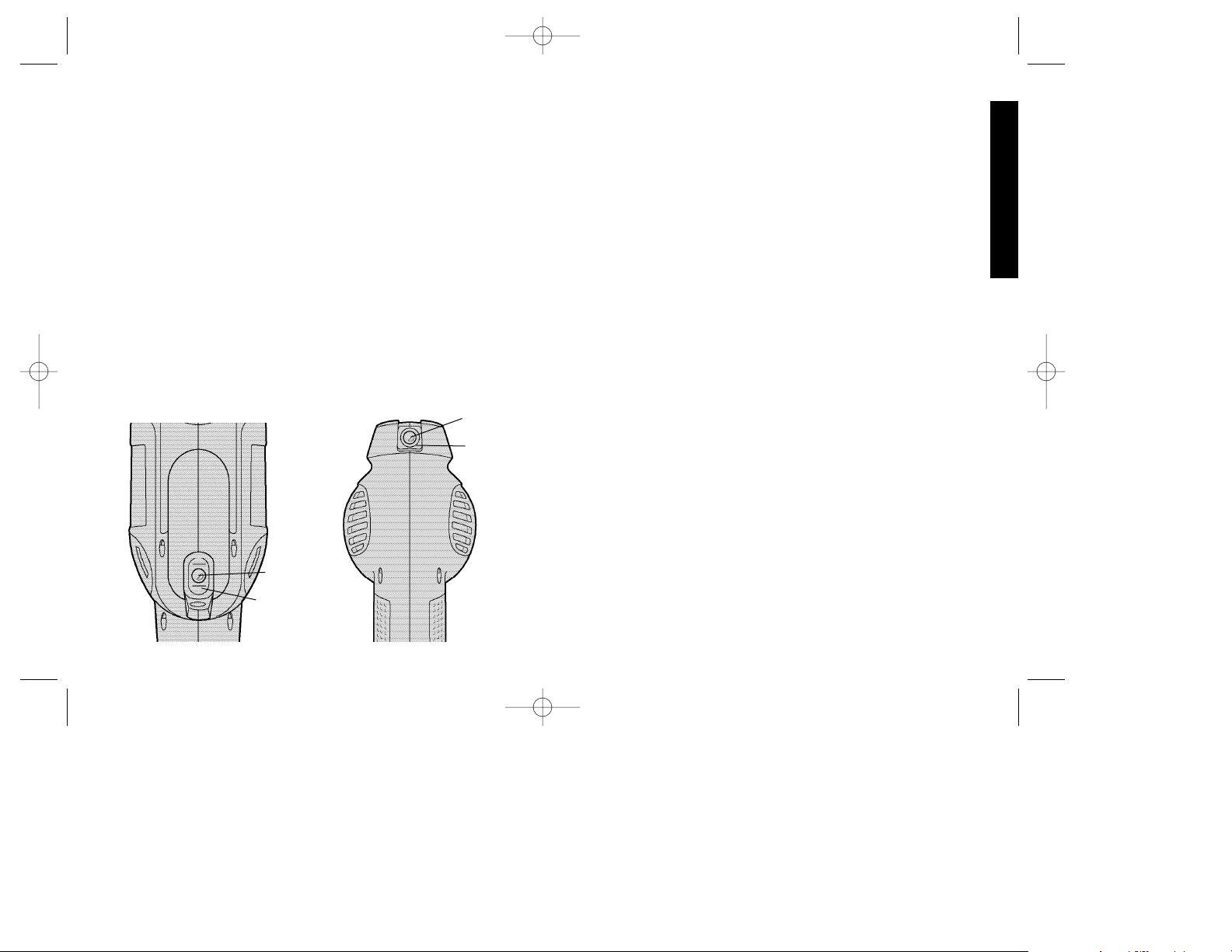
Bubble Level
Your drill is equipped with a bubble level that assists you in drilling
level holes.
For horizontal drilling, tilt the drill up or down as required so that the
bubble floats in the center of the parallel lines drawn on the glass.
When the bubble is centered between the lines, as shown in Figure
3A, the drill is level.
For vertical drilling, align the drill so that the bubble floats in the
center of the bull’s-eye, as shown in Figure 3B.
To assure accuracy, first place a level on your work piece and
position it so that it is level. Then, when the drill reads level, the two
will be aligned. (Any bubble level can only indicate level to the earth’s
surface.)
NOTE: The level is filled with mineral oil that may cause minor skin
irritation when contacted. If the level breaks and this fluid gets on
3
English
FIG. 3A
FIG. 3B
BUBBLE
BUBBLE
LEVEL
BUBBLE
BUBBLE
LEVEL
383945/DW100-220 5/3/02 1:15 PM Page 3
Page 7
4
your skin, rinse thoroughly with water. If any liquid gets in your eyes,
rinse thoroughly with water and call a physician immediately.
Chuck
Open chuck jaws by turning collar with fingers and insert shank of
bit about 3/4" into chuck. Tighten chuck collar by hand. Place chuck
key in each of the three holes, and tighten in clockwise direction. It’s
important to tighten chuck with all three holes. To release bit, turn
chuck counter clockwise in just one hole, then loosen the chuck by
hand.
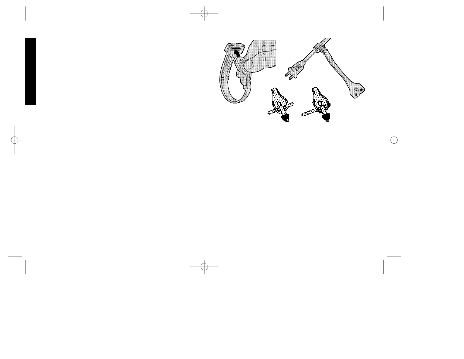
Chuck Key Holder
(May be installed already.)
1. Push double-hole end of holder through the slot in other end of
holder (Figure 4.)
2. Slip loop over electric plug and draw loop tight around cord
(Figure 5.)
3. Push ends of Chuck Key Handle through two holes in end of
holder (Figure 6.)
Chuck Removal
Place chuck key in any one of the three holes in the chuck, as shown
in Figure 7. Strike the key sharply in the counterclockwise direction
(when viewed from the front of the tool). This will loosen the chuck so
that it can be removed by hand.
Chuck Installation
Screw the chuck on by hand as far as it will go. Place the chuck key
in any of the three holes in the chuck and strike it sharply in the
clockwise direction (when viewed from the front of the tool) as shown
in Figure 8. (145-160 in. lbs. of torque is recommended.)
Lubrication
When the tool is taken apart for motor brush replacement a small
amount of grease should be added (or redistributed from that
remaining in housing) to the gears.
The ball bearings used in this tool are lubricated during manufacture
and require no lubrication.
Accessories
Recommended accessories for use with your tool are available at
extra cost from your local dealer or authorized service center. If you
need assistance in locating any accessory for your tool, please
contact your local dealer or authorized service center.
If you need assistance in locating any accessory, please contact
D
EWALT Industrial Tool Company, P.O. Box 158, 626 Hanover Pike,
Hampstead, MD 21074 or call 1-800-433-9258.
English
FIG. 5
FIG. 4
FIG. 6
383945/DW100-220 5/3/02 1:15 PM Page 4
Page 8

CAUTION: The use of any other accessory not recommended
for use with this tool could be hazardous.
For safety in use, the following accessories should be used only in
sizes up to the maximums shown in the table below.
MAXIMUM RECOMMENDED CAPACITIES
DRILL CAPACITY 3/8"
R.P.M. 0-2500
BITS, METAL DRILLING 3/8"
WOOD, FLAT BORING 1"
BITS, MASONRY DRILLING 1/2"
HOLE SAWS 1-1/8"
ACCESSORY MUST BE RATED FOR USE AT SPEED EQUAL TO
OR HIGHER THAN NAMEPLATE R.P.M. OF TOOL WITH WHICH IT
IS BEING USED.
WIRE WHEEL BRUSHES ....................4" Diameter Maximum
WIRE CUP BRUSHES ..........................3" Diameter Maximum
BUFFING WHEELS ..............................3" Diameter Maximum
RUBBER BACKING PADS....................4-5/8" Diameter Maximum
Important
To assure product SAFETY and RELIABILITY, repairs, maintenance
and adjustment (including brush inspection and replacement) should
be performed by authorized service centers or other qualified service
organizations, always using identical replacement parts.
Full Warranty
DEWALT heavy duty industrial tools are warranted for one year from
date of purchase. We will repair, without charge, any defects due to
faulty materials or workmanship. For warranty repair information,
call 1-800-4-D
EWAL T. This warranty does not apply to accessories or
damage caused where repairs have been made or attempted by
others. This warranty gives you specific legal rights and you may
have other rights which vary in certain states or provinces.
In addition to the warranty, D
EWALT tools are covered by our:
30 DAY NO RISK SATISFACTION GUARANTEE
If you are not completely satisfied with the performance of your
D
EWAL Theavy duty industrial tool, simply return it to the participating
seller within 30 days for a full refund. Please return the complete unit,
transportation prepaid. Proof of purchase may be required.
5
English
FIG. 7 FIG. 8
383945/DW100-220 5/3/02 1:15 PM Page 5
Page 9

6
Français
POUR TOUT RENSEIGNEMENT SUPPLÉMENTAIRE SUR CET
OUTIL OU TOUT AUTRE OUTIL D
EWALT, COMPOSER SANS
FRAIS LE NUMÉRO:
1 800 4-DEWALT (1 800 433-9258)
Importantes mesures de sécurité
AVERTISSEMENT : Afin de réduire les risques d’incendie, de
secousses électriques ou de blessures lorsqu’on utilise des outils
électriques, il faut toujours respecter les mesures de sécurité
suivantes.
LIRE TOUTES LES DIRECTIVES.
Double isolation
Les outils à double isolation comportent deux couches distinctes
d’isolant électrique ou une double épaisseur d’isolant qui protègent
l’utilisateur contre les risques de blessures provenant du système
électrique de l’outil. Ce système de double isolation élimine le besoin
de mettre les outils à la terre. En effet, l’outil est muni d’une fiche à
deux broches, ce qui permet d’utiliser une rallonge ordinaire sans
avoir à se soucier d’assurer la mise à la terre.
NOTE : La double isolation ne dispense pas des mesures de sécurité
normales lors de l’utilisation de l’outil. Elle vise à procurer une
protection supplémentaire contre les blessures que peut entraîner
une défectuosité de l’isolant électrique à l’intérieur de l’outil.
MISE EN GARDE : LORS DE L’ENTRETIEN, N’UTILISER QUE
DES PIÈCES DE RECHANGE IDENTIQUES. Réparer ou
remplacer les cordons endommagés.
Mesures de sécurité pour tous les outils
• BIEN DÉGAGER LA SURFACE DE TRAVAIL. Des surfaces et
des établis encombrés peuvent être la cause de blessures.
• TENIR COMPTE DU MILIEU DE TRAVAIL. Protéger les outils
électriques de la pluie. Ne pas s’en servir dans des endroits
humides ou mouillés. Bien éclairer la surface de travail. Ne pas se
servir de l’outil en présence de liquides ou de vapeurs
inflammables.
• SE PROTÉGER CONTRE LES SECOUSSES ÉLECTRIQUES.
INVERSEUR DE MARCHE
INTERRUPTEUR À
DÉTENTE
BOUTON DE
VERROUILLAGE
PINCE POUR LA CEINTURE
CROCHET DE
SUSPENSION
FICHE DE 220 VOLTS
383945/DW100-220 5/3/02 1:15 PM Page 6
Page 10

Éviter tout contact avec des objets mis à la terre, comme des
tuyaux, radiateurs, cuisinières, réfrigérateurs et autres objets du
genre.
• ÉLOIGNER LES ENFANTS. Tous les visiteurs doivent être tenus
à l’écart de l’aire de travail et il faut les empêcher de toucher à
l’outil ou au cordon de rallonge.
• RANGER LES OUTILS INUTILISÉS. Il faut ranger les outils dans
un endroit sec, situé en hauteur ou fermé à clé, hors de la portée
des enfants.
• NE JAMAIS FORCER L’OUTIL. Afin d’obtenir un rendement sûr
et efficace, utiliser l’outil à son rendement nominal.
• UTILISER L’OUTIL APPROPRIÉ. Ne jamais exiger d’un petit outil
ou d’un accessoire le rendement d’un outil de fabrication plus
robuste. Se servir de l’outil selon l’usage prévu.
• PORTER DES VÊTEMENTS APPROPRIÉS. Éviter de porter des
vêtements amples et des bijoux qui peuvent être happés par les
pièces en mouvement. Porter des gants de caoutchouc et des
chaussures à semelle antidérapante pour travailler à l’extérieur.
Protéger la chevelure si elle est longue.
• PORTER DES LUNETTES DE SÉCURITÉ. Porter également un
masque respiratoire si le travail de coupe produit de la poussière.
• NE PAS MANIPULER LE CORDON DE FAÇON ABUSIVE. Ne
pas transporter l’outil par le cordon ni tirer sur ce dernier pour le
débrancher de la prise. Éloigner le cordon des sources de chaleur,
des flaques d’huile et des arêtes tranchantes.
• ASSUJETTIR LA PIÈCE. Immobiliser la pièce à l’aide de brides
ou d’un étau. On peut alors se servir des deux mains pour faire
fonctionner l’outil, ce qui est plus sûr.
• NE PAS DÉPASSER SA PORTÉE. Toujours demeurer dans une
position stable et garder son équilibre.
• PRENDRE SOIN DES OUTILS. Conserver les outils propres pour
qu’ils donnent un rendement supérieur et sûr. Suivre les directives
concernant la lubrification et le remplacement des accessoires.
Inspecter régulièrement le cordon de l’outil et le faire réparer au
besoin à un atelier d’entretien autorisé. Inspecter régulièrement les
cordons de rallonge et les remplacer lorsqu’ils sont endommagés.
S’assurer que les poignées sont toujours propres, sèches et libres
de toute tache d’huile ou de graisse.
• DÉBRANCHER OU VERROUILLER EN POSITION HORS
TENSION LES OUTILS NON UTILISÉS. Respecter cette mesure
lorsqu’on ne se sert pas de l’outil, ou qu’on doit le réparer ou en
changer un accessoire (comme une lame, un foret ou un couteau).
• ENLEVER LES CLÉS DE RÉGLAGE. Prendre l’habitude de
vérifier si les clés de réglage ont été retirées avant de faire
démarrer l’outil.
• ÉVITER LES DÉMARRAGES ACCIDENTELS. Ne pas laisser le
doigt sur l’interrupteur lorsqu’on transporte l’outil. S’assurer que
l’interrupteur est à la position hors circuit lorsqu’on branche l’outil.
• CORDONS DE RALLONGE. S’assurer que le cordon de rallonge
est en bon état. Lorsqu’on se sert d’un cordon de rallonge,
s’assurer qu’il est de calibre approprié pour la tension nécessaire
au fonctionnement de l’outil. L’utilisation d’un cordon de calibre
inférieur occasionne une baisse de tension entraînant une perte de
puissance et la surchauffe. Le tableau suivant indique le calibre
approprié selon la longueur du cordon et les mentions de la plaque
signalétique de l’outil. En cas de doute, utiliser un cordon de calibre
supérieur. Le chiffre indiquant le calibre est inversement
proportionnel au calibre du cordon.
Calibre minimal des cordons de rallonge
Tension Longueur totale du cordon en pieds
120 V 0-25 26-50 51-100 101-150
240 V 0-50 51-100 101-200 201-300
Intensité (A)
Au Au Calibre moyen de fil (AWG)
moins plus
0-6 18161614
6 - 10 18 16 14 12
10-1216161412
12 - 16 14 12 Non recommandé
7
Français
383945/DW100-220 5/3/02 1:15 PM Page 7
Page 11

8
• CORDONS DE RALLONGE PRÉVUS POUR L’EXTÉRIEUR.
Lorsque l’outil est utilisé à l’extérieur, ne se servir que d’un cordon
de rallonge conçu pour l’extérieur et portant la mention appropriée.
• DEMEURER VIGILANT. Travailler avec vigilance et faire preuve
de bon sens. Ne pas se servir de l’outil lorsqu’on est fatigué.
• VÉRIFIER LES PIÈCES ENDOMMAGÉES. Avant de continuer à
utiliser l’outil, il faut vérifier si le protecteur ou toute autre pièce
endommagée remplit bien la fonction pour laquelle il a été prévu.
Vérifier l’alignement et les attaches des pièces mobiles, le degré
d’usure des pièces et leur montage, ainsi que tout autre facteur
susceptible de nuire au bon fonctionnement de l’outil. Faire réparer
ou remplacer tout protecteur ou toute autre pièce endommagée
dans un centre de service autorisé, sauf si le présent guide fait
mention d’un avis contraire. Confier le remplacement de tout
interrupteur défectueux à un centre de service autorisé. Ne jamais
se servir d’un outil dont l’interrupteur est défectueux.
• MISE EN GARDE : Lorsqu’on perce ou qu’on visse dans les
murs, les planchers ou tout autre endroit où peuvent se trouver des
fils sous tension, NE PAS TOUCHER AUX COMPOSANTS
MÉTALLIQUES DE L’OUTIL. Ne le saisir que par ses surfaces en
plastique afin de se protéger des secousses électriques si on entre
en contact avec un fil sous tension.
CONSERVER CES MESURES.
Balais du moteur
Les outils DEWALT sont dotés d’un système perfectionné de
vérification des balais qui arrête automatiquement l’outil lorsque les
balais sont usés afin d’empêcher d’endommager le moteur.
Interrupteurs
Pour mettre la perceuse en marche, enfoncer l’interrupteur à détente;
pour la mettre hors circuit, relâcher l’interrupteur à détente. Lorsqu’on
veut verrouiller l’outil en mode de fonctionnement continu, il suffit
d’enfoncer l’interrupteur à détente et le bouton de verrouillage (A),
illustrés à la figure 1, puis de relâcher lentement l’interrupteur. Pour
libérer le mécanisme de verrouillage, appuyer à fond sur
l’interrupteur à détente et le relâcher. Toujours s’assurer que le
bouton de verrouillage fonctionne bien avant d’utiliser l’outil (chaque
fois).
Ne pas verrouiller l’interrupteur en mode de fonctionnement continu
lorsqu’on perce à la main de façon à pouvoir relâcher immédiatement
la détente si le foret se coince dans le trou.
Utiliser le bouton de verrouillage seulement lorsque la perceuse est
immobilisée dans une presse ou autrement.
Veiller à ce que le bouton de verrouillage soit dégagé avant de
débrancher l’outil, sinon ce dernier se remettra immédiatement en
marche la prochaine qu’on s’en servira et cela présente des risques
de dommages et de blessures.
LE RÉGULATEUR DE VITESSE permet de contrôler la vitesse de
l’outil. Plus on enfonce l’interrupteur à détente, plus l’outil fonctionne
rapidement. NOTE : Se servir de la basse vitesse pour amorcer des
trous sans poinçon ainsi que pour percer les métaux, les plastiques
et la céramique, ainsi que pour enfoncer des vis. La vitesse élevée
convient mieux au perçage du bois et des panneaux d’agglomérés,
ainsi qu’à l’utilisation d’accessoires pour le ponçage et le polissage.
L’INVERSEUR DE MARCHE sert à sortir les vis ou les forets
bloqués. Il se trouve au-dessus de l’interrupteur à détente, comme
le montre la figure 2. Pour actionner la marche arrière, il faut
D’ABORD relâcher l’interrupteur à détente, puis faire glisser
l’inverseur de marche vers la droite. Après les travaux en marche
arrière, toujours remettre l’inverseur à la marche avant.
Français
383945/DW100-220 5/3/02 1:15 PM Page 8
Page 12

Fonctionnement
PERÇAGE
1. Toujours débrancher l’outil lorsqu’on en change les forets ou les
accessoires.
2. N’utiliser que des forets bien affûtés. Pour le BOIS : forets
hélicoïdaux, à langue d’aspic, de tarière ou des emporte-pièce;
pour le MÉTAL : forets hélicoïdaux en acier de coupe rapide ou
des emporte-pièce; pour la MAÇONNERIE (brique, ciment et
béton, etc.) : forets au carbure.
3. Veiller à ce que la pièce à percer soit solidement retenue ou fixée
en place. Afin d’éviter les avaries aux matériaux minces, les
adosser à un bloc de bois épais.
4. T oujours exercer la pression en ligne directe avec le foret. N’user
que de la force qu’il faut pour que le foret continue de percer;
éviter de trop forcer, ce qui pourrait faire caler le moteur ou
dévier le foret.
5. Saisir fermement la perceuse afin de contrer l’effet de torsion de
l’outil en marche.
6. LA PERCEUSE S’ÉTOUFFE habituellement lorsqu’elle est
surchargée ou utilisée de façon inappropriée. RELÂCHER
IMMÉDIATEMENT L’INTERRUPTEUR À DÉTENTE, retirer le
foret du matériau et déterminer la cause du blocage. ÉVITER DE
METTRE EN MARCHE ET HORS CIRCUIT L’OUTIL À L’AIDE
DE L’INTERRUPTEUR À DÉTENTE DANS LE BUT DE FAIRE
DÉMARRER LA PERCEUSE BLOQUÉE, CELA POURRAIT
L’ENDOMMAGER.
7. Afin de minimiser l’étouffement du moteur ou le défoncement de
la pièce, réduire la pression et faire avancer plus doucement le
foret vers la fin de sa course.
8. Laisser le moteur en marche lorsqu’on retire le foret d’un trou afin
d’éviter qu’il se coince.
9. Il n’est pas nécessaire de pratiquer un creux de guidage avec les
perceuses à régulateur de vitesse. Utiliser plutôt la basse vitesse
pour commencer le trou, puis accélérer en enfonçant plus
profondément l’interrupteur à détente lorsque le foret est
suffisamment inséré dans la pièce.
Perçage dans le métal
Utiliser de l’huile de coupe pour percer dans les métaux, sauf la fonte
et le laiton qui se percent à sec. L’huile de coupe la plus efficace est
l’huile sulfurisée ou l’huile de lard; la graisse de bacon est parfois
suffisante.
Perçage dans le bois
Les forets hélicoïdaux à métal peuvent servir à percer le bois, mais
il faut les retirer souvent du trou pour chasser les copeaux et
rognures des goujures afin d’éviter qu’ils ne surchauffent. Pour
percer de gros trous, utiliser les forets à bois d’une perceuse
électrique. Adosser les matériaux friables à un bloc de bois
quelconque.
9
Français
FIG. 1
A
FIG. 2
INVERSEUR DE
MARCHE
(illustré en marche
avant)
383945/DW100-220 5/3/02 1:15 PM Page 9
Page 13

10
Perçage dans la maçonnerie
Utiliser des forets à maçonnerie à basse vitesse. Exercer une
pression constante, sans forcer afin d’éviter de casser les matériaux
friables. Une production uniforme de poussière à débit moyen
indique un perçage convenable.
Niveau à bulle d’air
La perceuse est munie d’un niveau à bulle pour s’assurer que les
trous percés sont de niveau avec les plans horizontal ou vertical.
Dans le cas des trous percés à l’horizontale, placer la perceuse de
sorte que la bulle se trouve entre les repères (comme le montre la
figure 3A). À ce moment-là, la perceuse est de niveau avec le plan
horizontal.
Pour percer des trous à la verticale, il suffit de placer la perceuse
pour que la bulle flotte au centre du verre indicateur, comme l’illustre
la figure 3B.
Pour obtenir une plus grande précision, mettre un niveau sur la pièce
à percer et placer cette dernière de niveau. Puis, aligner la perceuse,
qui est de niveau, sur la pièce. (Tous les niveaux n’indiquent que le
niveau par rapport au champ de gravitation de la terre.)
NOTE : Le niveau contient de l’huile minérale qui peut causer une
légère irritation au contact de la peau. Si le niveau se brise et que
l’huile entre en contact avec la peau, bien la rincer avec de l’eau. Si
le liquide entre en contact avec les yeux, les rincer à fond avec de
l’eau, puis téléphoner immédiatement à un médecin.
Mandrin
Ouvrir les mâchoires du mandrin en tournant le collet à la main et y
insérer environ 19 mm (3/4 po) de l’arbre du foret. Resserrer la
bague du mandrin à la main. Placer la clé du mandrin dans chacun
des trois trous et serrer dans le sens horaire. Il est essentiel de bien
serrer les trois trous du mandrin. Pour dégager le foret, il suffit de
Français
FIG. 3A
FIG. 3B
BULLE
NIVEAU
À BULLE
BULLE
NIVEAU
À BULLE
FIG. 5
FIG. 4
FIG. 6
383945/DW100-220 5/3/02 1:15 PM Page 10
Page 14

faire tourner la clé du mandrin dans le sens antihoraire dans l’un
des trous, puis de desserrer le mandrin à la main.
Porte-clé du mandrin
(Peut être déjà installé.)
1. Insérer l’extrémité à deux trous du porte-clé dans la fente qui se
trouve à l’autre extrémité du porte-clé (fig. 4).
2. Faire glisser la boucle sur la fiche du cordon et bien serrer la
boucle autour du cordon (fig. 5).
3. Passer les extrémités de la clé du mandrin dans les deux trous
du porte-clé (fig. 6).
Retrait du mandrin
Placer la clé du mandrin dans l’un des trois trous du mandrin de la
façon illustrée à la figure 7. Frapper la clé dans le sens antihoraire
(lorsqu’on se place à l’avant de l’outil). On desserre ainsi le mandrin
de façon à pouvoir le retirer à la main.
Installation du mandrin
Visser à fond le mandrin à la main. Placer la clé du mandrin dans l’un
des trois trous du mandrin et la frapper dans le sens horaire
(lorsqu’on se place à l’avant de l’outil), comme le montre la figure 8.
(Il est recommandé d’exercer un couple variant entre 145 et 160 lbpo.)
Lubrification
Il est conseillé d’ajouter une quantité minimale de graisse aux
engrenages lorsqu’on remplace les balais (ou de redistribuer la
graisse qui reste dans le boîtier).
Les roulements à billes de cet outil ont été lubrifiés en usine et il n’est
pas nécessaire de les lubrifier de nouveau.
Accessoires
On peut se procurer séparément les accessoires recommandés pour
l’outil chez les détaillants ou au centre de service de la région. Pour
trouver un accessoire, prière de communiquer avec les détaillants ou
le personnel du centre de service de la région.
Pour trouver un accessoire, prière de communiquer avec D
EWALT
Industrial Tool Company, 626 Hanover Pike, P.O. Box 158,
Hampstead, MD 21074, É.-U., ou composer sans frais le
1 (800) 433-9258).
MISE EN GARDE : L’utilisation de tout accessoire non
recommandé peut être dangereuse.
Par mesure de sécurité, n’utiliser que les accessoires suivants et
uniquement ceux ne dépassant pas les dimensions maximales
recommandées.
11
Français
FIG. 7
FIG. 8
383945/DW100-220 5/3/02 1:15 PM Page 11
Page 15

12
CAPACITÉS MAXIMALES RECOMMANDÉES
CAPACITÉ DE LA PERCEUSE 3/8 po
RÉGIME (trs/min) De 0 à 2 500
FORETS À MÉTAUX 3/8 po
FORETS À BOIS 1 po
FORETS À MAÇONNERIE 1/2 po
EMPORTE-PIÈCE 1 1/8 po
LA VITESSE NOMINALE DES ACCESSOIRES DOIT ÊTRE ÉGALE
OU SUPÉRIEURE AU RÉGIME DE L'OUTIL (INDIQUÉ SUR LA
PLAQUE SIGNALÉTIQUE DE CE DERNIER) AVEC LEQUEL ILS
SONT UTILISÉS.
MEULES MÉTALLIQUES......................4 po max. de diamètre
MEULES-BOISSEAUX
MÉTALLIQUES......................................3 po max. de diamètre
COIFFES À POLIR................................3 po max. de diamètre
DISQUE D'APPUI EN
CAOUTCHOUC....................................4 5/8 po max. de diamètre
Important
Pour assurer la SÉCURITÉ D’EMPLOI et la FIABILITÉ de l’outil, n’en
confier la réparation, l’entretien et les rajustements (y compris
l’inspection des balais) qu’à un centre de service ou à un atelier
d’entretien autorisé n’utilisant que des pièces de rechange
identiques.
Garantie complète
Les outils industriels de service intensif DEWALT sont garantis
pendant un an à partir de la date d’achat. Toute pièce d’un outil
D
EWALT qui s’avérait défectueuse en raison d’un vice de matière ou
de fabrication sera réparée sans frais. Pour obtenir de plus amples
renseignements sur les réparations couvertes para garantie,
composer le 1 (800)4-D
EWALT. Il suffit de retourner l’outil complet à
un centre de service D
EWALT. La présente garantie ne couvre pas
les accessoires ni les avaries dues aux réparations tentées ou
effectuées par des tiers. Les modalités de la présente garantie
donnet des droits légaux spécifiques. L'utilisateur peut également
se prévaloir d'autres droits selon l'état ou la province qu'il habite.
En outre, la garantie suivante couvre les outils D
EWALT .
GARANTIE DE SATISFACTION DE 30 JOURS OU ARGENT
REMIS
Si, pour quelque raison que ce soit, l’outil ne donne pas entière
satisfaction, il suffit de le retourner où il a été acheté dans les 30 jours
suivant la date d’achat afin d’obtenir un remboursement intégral.
Prière de retourner l'outil complet port payé. Une preuve d'achat peut
être requise.
Français
383945/DW100-220 5/3/02 1:15 PM Page 12
Page 16

Instrucciones importantes de seguridad
ADVERTENCIA: Es indispensable sujetarse a las precauciones
básicas de seguridad, con la finalidad de reducir el peligro de
incendio, choque eléctrico y lesiones personales, en todas las
ocasiones en que se utilicen herramientas eléctricas. Entre estas
precauciones se incluyen la siguientes:
LEA TODAS LAS INSTRUCCIONES
Doble aislamiento
Las herramientas DOBLEMENTE aisladas se han elaborado de
manera integral con dos capas separadas de aislamiento eléctrico o
una capa doble de aislamiento entre usted y el sistema eléctrico
que contienen. Las herramientas construidas con este sistema de
aislamiento no requieren conectarse a tierra. Como resultado su
herramienta está equipada con una clavija de dos patas que le
permite emplear cordones de extensión sin preocuparse por tener
una conexión a tierra.
NOTA: El doble aislamiento no substituye a las precauciones
normales de seguridad cuando se opera esta herramienta. La
finalidad de este sistema de aislamiento es ofrecer a usted
protección añadida contra lesiones resultantes de fallas en el
aislamiento eléctrico interno de la herramienta.
PRECAUCION: UTILICE SOLAMENTE REFACCIONES
ORIGINALES CUANDO HAGA SERVICIO a cualquier herramienta.
Repare o reemplace los cordones eléctricos dañados.
Instrucciones de seguridad para todas
las herramientas
• CONSERVE LIMPIA LA ZONA DE TRABAJO. Las superficies y
los bancos con objetos acumulados en desorden propician los
accidentes.
13
Español
PALANCA DE REVERSA
GATILLO INTERRUPTOR
BOTON DE ENCENDIDO
PERMANENTE
PINZA PARA EL CINTURON
ARILLO PARA
COLGAR
CLAVIJA PARA 220
VOLTS
383945/DW100-220 5/3/02 1:15 PM Page 13
Page 17

14
• OTORGUE PRIORIDAD A LA ZONA DE TRABAJO. No deje las
herramientas eléctricas expuestas a la lluvia. No las utilice en
lugares inundados o mojados. Conserve bien iluminada la zona de
trabajo. No utilice la herramienta en presencia de líquidos o gases
inflamables.
• PROTEJASE CONTRA EL CHOQUE ELECTRICO. Evite el
contacto corporal con superficies aterrizadas, por ejemplo,
tuberías, radiadores, antenas y gabinetes de refrigeración.
• CONSERVE APARTADOS A LOS NIÑOS. No permita que los
visitantes toquen las herramientas o los cables de extensión.
Todos los visitantes deben estar alejados de la zona de trabajo.
• GUARDE LAS HERRAMIENTAS QUE NO EMPLEE. Las
herramientas que no se utilizan deben guardarse en un lugar seco
y elevado o bajo llave — fuera del alcance de los niños.
• NO FUERCE LA HERRAMIENTA.Esta cumplirá su función mejor
y con más seguridad a la velocidad y la presión para las que se
diseñó.
• EMPLEE LA HERRAMIENTA ADECUADA. No fuerce a una
herramienta pequeña o a sus dispositivos de montaje en un
trabajo de tipo pesado. No emplee la herramienta en una tarea
para la que no se diseñó.
• VISTASE DE LA MANERA ADECUADA.No use ropas o artículos
de joyería flojos, pues podrían quedar atrapados por las partes
móviles de las herramientas. Se recomienda el empleo de guantes
de caucho y calzado antiderrapante cuando se trabaje al aire libre.
Cúbrase bien la cabeza para sujetarse el cabello si lo tiene largo.
• COLOQUESE ANTEOJOS DE SEGURIDAD. Póngase también
una mascarilla contra el polvo si lo produce la operación que va a
efectuar.
• TENGA CUIDADO CON EL CORDON ELECTRICO. Nunca
levante la herramienta tomándola por el cordón, ni tire de éste para
desconectarlo del enchufe. Apártelo del calor y los objetos
calientes, las substancias grasosas y los bordes cortantes.
• ASEGURE LOS OBJETOS SOBRE LOS QUE TRABAJE. Utilice
prensas o tornillos de banco para sujetar los objetos sobre los
que va a trabajar. Esto ofrece mayor seguridad que sujetar los
objetos con la mano, y además deja libres ambas manos para
operar la herramienta.
• CONSERVE EL EQUILIBRIO. Conserve en todo momento bien
apoyados los pies, lo mismo que el equilibrio.
• CUIDE SUS HERRAMIENTAS. Conserve sus herramientas
afiladas y limpias para que funcionen mejor y con mayor
seguridad. Siga las instrucciones para lubricación y cambio de
accesorios de su unidad. Revise periódicamente el cordón
eléctrico y hágalo reparar o reemplazar por un centro de servicio si
está dañado. Cambie los cordones de extensión si están dañados.
Conserve las empuñaduras secas, limpias y libres de aceite y
grasa.
• DESCONECTE Y APAGUE LAS HERRAMIENTAS cuando no las
use, antes de darles servicio y cuando cambie accesorios, tales
como discos, brocas y otros dispositivos de corte.
• RETIRE LAS LLAVES DE AJUSTE Y DE TUERCAS. Adquiera
el hábito de asegurarse que se han retirado las llaves de ajuste
de las herramientas antes de accionarlas.
• EVITE QUE LA HERRAMIENTA SE ACCIONE
ACCIDENTALMENTE.Nunca sostenga una herramienta que está
conectada con el dedo en el interruptor. Asegúrese que el
interruptor está en posición de “apagado” antes de conectar la
unidad.
• CORDONES DE EXTENSION. Asegúrese que su cordón de
extensión esté en buenas condiciones. Cuando utilice un cordón
de extensión, asegúrese que tenga el calibre suficiente para
soportar la corriente necesaria para su herramienta. Un cordón
eléctrico con calibre insuficiente causará una caída en el voltaje de
la línea, resultando en pérdida de potencia y sobrecalentamiento.
La tabla siguiente ilustra el calibre correcto que debe utilizarse de
conformidad con la longitud del cordón y el amperaje descrito por
la placa de identificación. Si tiene alguna duda, utilice el cable con
Español
383945/DW100-220 5/3/02 1:15 PM Page 14
Page 18

el calibre siguiente (mayor). Mientras más chico sea el número,
mayor será su calibre.
Calibre mínimo para cordones de extensión
Volts Longitud total del cordón en metros
120V 0-7,6 7,6-15,2 15,2-30,4 30,4-45,7
240V 0-15,2 15,2-30,4 30,4-60,9 60,9-91,4
AMPERAJE
MásNo más Calibre del cordón AWG
de de
0- 6 18 16 16 14
6 - 10 18 16 14 12
10 - 12 16 16 14 12
12 - 16- 14 12 No recomendado
• CORDONES DE EXTENSION PARA INTEMPERIE. Cuando
opere su herramienta a la intemperie, utilice únicamente cordones
de extensión diseñados y marcados para este fin.
• NO SE DISTRAIGA. Concéntrese en lo que está haciendo.
Recurra al sentido común. No opere ninguna herramienta si está
fatigado.
• VERIFIQUE LAS PARTES DAÑADAS. Antes de seguir
empleando cualquier herramienta, es indispensable verificar con
mucho cuidado que las guardas u otras partes dañadas puedan
operar de la manera adecuada para cumplir con su función.
Verifique la alineación de las partes móviles, la firmeza con que
deben encontrarse sujetas a sus montaduras, las partes rotas, las
propias montaduras y cualesquiera otros detalles que pudieran
afectar la operación de la herramienta. Las guardas y otras partes
que se encuentren dañadas deberán cambiarse o repararse en un
centro de servicio autorizado, a menos que se diga otra cosa en
el manual del usuario. Haga que se cambien los interruptores
dañados en un centro de servicio autorizado. No emplee ninguna
herramienta que tenga estropeado o inutilizado el interruptor.
PRECAUCION: Cuando taladre o atornille en muros, pisos o
dondequiera que pueda encontrar cables eléctricos vivos, ¡NO
TOQUE NINGUNA PARTE METALICA DE LA HERRAMIENTA!
Sujete la herramienta únicamente por las superficies aislantes
(empuñaduras) para evitar el choque eléctrico si hace contacto
con un cable eléctrico vivo.
CONSERVE ESTAS INSTRUCCIONES
Carbones del motor
DEWALT utiliza un avanzado sistema de carbones que detiene
automáticamente el motor del taladro cuando se desgastan estas
piezas. Esto impide que el motor se dañe seriamente.
Interruptores
Oprima el interruptor de gatillo para accionar el taladro; suéltelo para
detenerlo. Para dejar fijo el interruptor en la posición de encendido a
fin de que opere de manera continua, oprímalo y presione el botón
de encendido permanente “A” (fig. 1), y suelte a continuación el
gatillo interruptor con suavidad. Para liberar el mecanismo de
trabado, oprima el gatillo hasta el fondo y suéltelo. Antes de utilizar
la herramienta (cada vez) asegúrese que el mecanismo del seguro
funciona libremente.
No asegure el interruptor en la posición de encendido permanente
cuando taladre a mano, de manera que pueda soltarlo si la broca se
atasca en el barreno.
El botón de encendido permanente se debe utilizar solamente
cuando el taladro se encuentra montado en una prensa o en un
banco.
Asegúrese de liberar el botón de encendido permanente antes de
desconectar la clavija de la toma de corriente. No hacerlo propiciará
que el taladro se encienda en el momento de volver a conectarlo,
con el peligro consecuente de daños o lesiones.
EL INTERRUPTOR DE GATILLO DE VELOCIDAD VARIABLE
permite controlar la velocidad. Cuanto más a fondo se oprima el
gatillo, mas elevada será la velocidad del taladro.
15
Español
383945/DW100-220 5/3/02 1:15 PM Page 15
Page 19

16
NOTA: Utilice velocidades bajas para perforar sin haber marcado el
“punto” de centro, taladrar en metal o plásticos, atornillar y perforar
cerámica. Las altas velocidades son mejores para barrenar madera
y aglomerados de ésta, y cuando se van a utilizar los accesorios
abrasivos y de pulido.
LA PALANCA DE REVERSA se utiliza para sacar las brocas
atascadas en barrenos muy apretados y para destornillar. Se
encuentra situada por arriba del interruptor de gatillo (fig. 2). Para
activar el motor en reversa, suelte PRIMERO el gatillo y, a
continuación, mueva la palanca hacia la derecha. Después de haber
efectuado una operación en reversa, devuelva la palanca hacia la
posición de marcha hacia adelante.
Operación
PARA TALADRAR
1. Desconecte siempre el taladro antes de poner o cambiar brocas
o accesorios.
2. Utilice exclusivamente brocas afiladas. Para taladrar MADERA
emplee brocas helicoidales, brocas de horquilla o brocas sierra.
Para taladrar METAL use brocas helicoidales de alta velocidad o
brocas sierra. Para taladrar MAMPOSTERIA, ladrillo, cemento,
etc., utilice brocas con punta de carburo de tungsteno.
3. Asegúrese de que el material que va a taladrar este firmemente
anclado o afianzado. Si perfora material delgado, aplique al
mismo un respaldo de madera para evitar dañarlo.
4. Aplique presión a la broca en línea recta. Haga suficiente presión
para que la broca siga perforando, pero no tanta para que el
motor se atasque o la broca se desvíe.
5. Sujete la herramienta firmemente para controlar la acción de
torsión de la broca.
6. SI EL TALADRO SE TRABA, esto se deberá posiblemente a que
está sobrecargado o que se está utilizando en forma indebida.
SUELTE EL GATILLO DE INMEDIATO, retire la broca del
barreno y determine la causa del atascamiento. NO APRIETE
EL GATILLO PARA HACER PRUEBAS DE ENCENDIDO Y
APAGADO, PUES PODRIA DAÑARLO.
7. Para reducir el peligro de que se atasque el taladro, reduzca la
presión y deje ir suavemente la broca hacia el final del barreno.
8. Conserve el motor trabajando al retirar la broca del interior del
barreno. De esta manera evitará que se atasque.
9. Con los taladros de velocidad variable no hay necesidad de poner
un “punto” de centrado para iniciar los barrenos. Utilice velocidad
baja para iniciar la perforación, y acelere oprimiendo el gatillo
cuando el barreno tenga suficiente profundidad.
Taladrado en metal
Utilice un lubricante para corte cuando perfore metales, excepto en
los casos de hierro colado o latón en los que se deberá taladrar en
seco. Los lubricantes más adecuados para corte son los de aceite
sulfúrico y la manteca de cerdo.
Español
FIG. 1
A
FIG. 2
PALANCA DE
REVERSA (mostrada
en posición de marcha
hacia adelante)
383945/DW100-220 5/3/02 1:15 PM Page 16
Page 20

Taladrado en madera
Los barrenos en madera pueden hacerse con las mismas brocas
que se utilizan para metal. Para evitar que las brocas se
sobrecalienten, deben sacarse frecuentemente del barreno para
quitar las virutas acumuladas en las estrías. Para hacer
perforaciones más grandes, emplee brocas de poder para madera.
El material que podría astillarse debe protegerse con un respaldo
de madera.
Taladrado en mampostería
Utilice brocas con punta de carburo de tungsteno a bajas
velocidades. Conserve uniforme la presión sobre el taladro, pero no
al grado que se despostillen los materiales. La salida continua de
volutas de polvo indica que se esta aplicando la velocidad apropiada.
Nivel de burbuja
Su taladro viene equipado con un nivel de burbuja, de utilidad para
perforar barrenos a nivel.
Para el taladrado horizontal mueva su unidad hacia arriba o hacia
abajo para que la burbuja, al flotar, vaya desplazándose hacia las
líneas paralelas grabadas en el vidrio. El taladro estará nivelado
una vez centrada la burbuja entre las líneas, como se ilustra en la
figura 3A.
Para el taladrado vertical, se debe alinear el taladro de manera que
la burbuja flote en el centro del ojo de buey, como se ilustra en la
figura 3B.
Para garantizar la precisión, coloque primero un nivel sobre la pieza
en la que esté trabajando y nivélela; a continuación, cuando el
taladro se encuentre nivelado, lo estarán entre si éste y la pieza de
trabajo. (Los dispositivos de burbuja pueden indicar sólo el nivel de
la superficie de la tierra).
NOTA: el nivel contiene aceite mineral, sustancia que podría
producir irritaciones menores de la piel al entrar en contacto con ella.
Si el nivel se rompiera y se derramara su contenido sobre su piel,
lávesela con agua en abundancia. Si le cayera en los ojos, láveselos
con agua en abundancia y llame de inmediato al médico.
Portabrocas
Abra las mordazas del portabrocas girando el collarín con los dedos
e inserte el vástago de la broca aproximadamente 19 mm dentro del
portabrocas. Apriete el collarín del portabrocas a mano. Coloque la
llave del portabrocas en cada uno de los tres orificios, y apriete en
el sentido de las manecillas del reloj. Es muy importante apretar el
portabrocas desde los tres orificios. Para sacar una broca, gire el
portabrocas en sentido contrario a las manecillas del reloj, desde uno
de los orificios, y después continúe a mano.
Porta llave
(Puede estar ya instalado.)
1. Empuje el extremo del porta llave que tiene dos orificios a través
de la ranura que se encuentra en el otro extremo (figura 4.)
17
Español
FIG. 3A
FIG. 3B
BURBUJA
NIVEL DE
BURBUJA
BURBUJA
NIVEL DE
BURBUJA
383945/DW100-220 5/3/02 1:15 PM Page 17
Page 21

18
2. Deslice el aro que se formó sobre la clavija y apriételo alrededor
del cable (figura 5).
3. Pase los extremos del asa de la llave a través de los dos orificios
del extremo del porta llave (figura 6.)
Remoción del portabrocas
Coloque la llave del portabrocas en uno de los tres orificios de éste,
como se observa en la figura 7. Aplique un golpe seco a la llave en
el sentido de las manecillas del reloj (visto desde el frente de la
herramienta). Esto aflojará el portabrocas para poder destornillarlo
a mano.
Instalación del portabrocas
Atornille el portabrocas a mano tanto como sea posible. Coloque la
llave en cualquiera de los tres orificios del portabrocas y aplíquele un
golpe seco en sentido contrario a las manecillas del reloj (viendo la
herramienta desde el frente) como se observa en la figura 8. (Se
recomienda aplicar un torque de 145 a 160 in. lbs.)
Lubricación
Cuando se lleve la herramienta a que le cambien los carbones, debe
añadírsele una pequeña cantidad de grasa (o debe redistribuirse de
la que queda en la carcaza) a los engranes.
Los baleros empleados en esta herramienta se lubricaron durante el
proceso de manufactura y no requieren lubricación.
Accesorios
Dispone usted de los accesorios para su herramienta por un cargo
adicional con su distribuidor local autorizado. Si necesita ayuda para
encontrar cualquier accesorio, por favor comuníquese al 326-7100.
Español
FIG. 5
FIG. 4
FIG. 6
FIG. 7 FIG. 8
383945/DW100-220 5/3/02 1:15 PM Page 18
Page 22

PRECAUCION: El empleo de cualquier otro accesorio no
recomendado para utilizarse con esta herramienta puede ser
peligroso.
Por seguridad en el uso, los siguientes accesorios deberán utilizarse
solamente en tamaños iguales o menores señalados en la tabla a
continuación.
CAPACIDADES MAXIMAS RECOMENDADAS
CAPACIDAD DEL TALADRO 9,5 mm (3/8”)
R.P.M. 0-2500
BROCAS PARA METAL 9,5 mm (3/8”)
BROCAS PARA MADERA 25,4 mm (1”)
BROCAS PARA MAMPOSTERIA 12,7 mm (1/2”)
BROCAS SIERRA 28,5 mm (1-1/8”)
EL ACCESORIO DEBE ESTAR CLASIFICADO PARA UTILIZARSE
A UNA VELOCIDAD IGUAL O MAYOR QUE LAS R.P.M.
SEÑALADAS EN LA PLACA DE IDENTIFICACION DE LA
HERRAMIENTA QUE SE ESTE EMPLEANDO.
CEPILLOS DE ALAMBRE........Diámetro máximo 101,6 mm (4")
CEPILLOS DE COPA ..............Diámetro máximo 76,2 mm (3")
BONETES PARA PULIR..........Diámetro máximo 76,2 mm (3")
RESPALDOS DE GOMA..........Diámetro máximo 117,4 mm (4-5/8")
Importante
Para garantizar la SEGURIDAD y la CONFIABILIDAD, deberán
hacerse reparaciones, mantenimiento y ajustes de esta herramienta
en los centros de servicio para herramientas industriales de D
EWALT .
u otras organizaciones calificadas. Estas organizaciones prestan
servicio a las herramientas D
EWALTy emplean siempre refacciones
legítimas D
EWALT.
PARA REPARACION Y SERVICIO DE SUS HERRAMIENTAS
ELECTRICAS FAVOR DE DIRIGIRSE AL CENTRO DE SERVICIO MAS
CERCANO
CULIACAN
Av . Nicolas Bravo #1063 Sur (91 671) 242 10
GAUDALAJARA
Av . La Paz #1779 (91 3) 826 69 78.
MEXICO
Eje Lázaro Cárdenas No. 18 Local D, Col. Obrera 588-9377
MERIDA
Calle 63 #459-A (91 99) 23 54 90
MONTERREY
Av . Francisco I. Madero Pte. 1820-A (91 83) 72 11 25
PUEBLA
17 Norte #205 (91 22) 46 37 14
QUERETARO
Av . Madero 139 Pte. (91 42) 14 16 60
SAN LOUIS POTOSI
Pedro Moreno #100 Centro (91 48) 14 25 67
TORREON
Blvd. Independencia, 96 pte. (91 17) 16 52 65
VERACRUZ
Prolongación Diaz Miron #4280 (91 29) 21 70 16
VILLAHERMOSA
Constitucion 516-A (91 93) 12 53 17
PARA OTRAS LOCALIDADES LLAME AL: 326 7100
19
Español
383945/DW100-220 5/3/02 1:15 PM Page 19
Page 23

20
Garantía Completa
Las herramientas industriales DEWalt están garantizadas durante un año a
partir de la fecha de compra. Repararemos, sin cargos, cualquier falla debida
a material o mano de obra defectuosos. Por favor regrese la unidad completa,
con el transporte pagado, a cualquier Centro de Servicio para Herramientas
Industriales de D
EWalt o a las estaciones de servicio autorizado enlistadas
bajo "Herramientas Eléctricas" en la Sección Amarilla. Esta garantía no se
aplica a los accesorios ni a daños causados por reparaciones efectuadas
por terceras personas. Esta garantía le otorga derechos legales específicos,
y usted puede tener otros derechos que pueden variar de estado a estado.
En adición a la garantía, las herramientas DEWALT están amparadas por
nuestra:
GARANTÍA DE SATISFACCIÓN SIN RIESGO POR 30 DÍAS
Si usted no se encuentra completamente satisfecho con el desempeño de
su herramienta industrial DEWalt, sencillamente devuélvala a los vendedores
participantes durante los primeros 30 días después de la fecha de compra
para que le efectúen un reembolso completo. Por favor regrese la unidad
completa, con el transporte pagado. Se puede requerir prueba de compra
Español
Epecificaciones (DW100-220)
Tensión de alimentación 220/240 V CA
Potencia nominal: 644/662 W
Frecuencia de operación:50/60 Hz
Consumo de corriente: 3,5/3,6 A
IMPORTADO: DEWALT S.A. DE C.V.
BOSQUES DE CIDROS ACCESO RADIATAS NO. 42
COL. BOSQUES DE LAS LOMAS.
05120 MÉXICO, D.F
TEL. 326-7100
Para servicio y ventas consulte
“HERRAMIENTAS ELECTRICAS”
en la sección amarilla.
383945/DW100-220 5/3/02 1:15 PM Page 20
 Loading...