


Model 1600-N1P
Model 6400-N1P
NEMA 1 Control Panel
Operator’s Installation and Instruction Manual
The Woodlands, Texas 77387
Ph.281.367.4100 / Fax 281.298.2868
Sept 27, 2007 • Document #3352 • Revision 1.1
DETCON, Inc.
3200 Research Forest Dr.,
www.detcon.com

1600/6400-N1P
This page left intentionally blank
1600/6400-N1P- Instruction Manual ii

1600/6400-N1P
Table of Contents
1.0 Description................................................................................................................................................ 1
2.0 System Configuration.............................................................................................................................. 2
3.0 Installation................................................................................................................................................ 3
3.1 Installing the I/O Modules.................................................................................................................... 6
3.2 Connecting to the I/O Modules ............................................................................................................ 6
4.0 Start-Up.................................................................................................................................................... 9
4.1 Applying Power.................................................................................................................................... 9
4.2 Setting Device Identification on the I/O Modules................................................................................ 9
5.0 Operator Interface................................................................................................................................. 10
5.1 Using the Touch-screen Display ........................................................................................................ 10
5.2 Main Display...................................................................................................................................... 10
5.3 Program Menu Selections .................................................................................................................. 12
5.3.1 Select # Active Channels and Relays.............................................................................................................12
5.3.2 Modbus™ Addressing and Relay Type.........................................................................................................12
5.3.3 Select Gas Type and Range ...........................................................................................................................16
5.3.4 Set Active Alarm Levels................................................................................................................................16
5.3.5 View Alarm History.......................................................................................................................................17
5.3.6 View Tag Information....................................................................................................................................17
5.3.7 Edit Date and Time........................................................................................................................................18
5.3.8 4-20mA Output Setup....................................................................................................................................18
5.3.9 View Channel History....................................................................................................................................19
5.4 Touch Screen Utilities........................................................................................................................ 20
5.5 Dipswitch Settings.............................................................................................................................. 20
6.0 Password Protection.............................................................................................................................. 20
7.0 Secondary Modbus™ Port.................................................................................................................... 21
8.0 System Expansions................................................................................................................................. 25
9.0 Troubleshooting..................................................................................................................................... 25
10.0 Spare Parts............................................................................................................................................. 25
11.0 Specifications.......................................................................................................................................... 26
12.0 Warranty................................................................................................................................................ 27
13.0 1600/6400-N1P Configuration .............................................................................................................. 27
14.0 Appendix................................................................................................................................................. 29
14.1 RS-485 System Integration Wiring.................................................................................................... 29
14.2 Hexadecimal Table............................................................................................................................. 34
14.3 Drawings ............................................................................................................................................ 35
Table of Figures
Figure 1 Block Diagram....................................................................................................................................... 1
Figure 2 System Configurations........................................................................................................................... 2
Figure 3 Unit Mounting and Dimensional............................................................................................................ 3
Figure 4 No Comm. Fault Relay and Serial Communications PCB’s.................................................................. 4
Figure 5 Interconnect Wiring Diagram................................................................................................................ 5
Figure 6 I/O Module Installation .......................................................................................................................... 6
Figure 7 Model DA-4 and 4-20mA Gas Sensors ................................................................................................. 6
Figure 8 Modbus™ Gas Sensor Connections....................................................................................................... 7
Figure 9 Model RL-4 Relay Module.................................................................................................................... 7
Figure 10 Model AO-4 Module............................................................................................................................ 8
1600/6400-N1P- Instruction Manual iii

1600/6400-N1P
Figure 11 Model DI-4 Module............................................................................................................................. 8
Figure 12 Power In............................................................................................................................................... 9
Figure 13 Setting Device Addresses................................................................................................................... 10
Figure 14 Main Display...................................................................................................................................... 11
Figure 15 Program Menu ................................................................................................................................... 12
Figure 16 Set # Active Channels and Relays ..................................................................................................... 12
Figure 17 Addressing DA Modules.................................................................................................................... 13
Figure 18 Addressing Gas Channels .................................................................................................................. 13
Figure 19 Addressing Relay Modules................................................................................................................ 15
Figure 20 Addressing & Set-up of Relay Outputs.............................................................................................. 15
Figure 21 Select Gas Type ................................................................................................................................. 16
Figure 22 Set Alarm Level................................................................................................................................. 16
Figure 23 View Alarm History........................................................................................................................... 17
Figure 24 View Tag Information........................................................................................................................ 18
Figure 25 Set Time and Date.............................................................................................................................. 18
Figure 26 Set-up 4-20mA Outputs..................................................................................................................... 19
Figure 27 View Channel History........................................................................................................................ 19
Figure 28 Screen Utilities...................................................................................................................................20
Figure 29 Non-Protected vs. protected............................................................................................................... 21
Figure 30 Dip-switches ...................................................................................................................................... 21
Figure 31 RTU Addressing ................................................................................................................................ 22
Figure 32 RS-485 Bus with 4 transceiver chips................................................................................................. 29
Figure 33 Correct and incorrect wiring schemes................................................................................................ 30
Figure 34 Unbalanced Data Bus......................................................................................................................... 31
Figure 35 Data Bus using two repeaters............................................................................................................. 31
Figure 36 Daisy Chain wiring diagram.............................................................................................................. 32
Figure 37 Unbalanced Data Bus......................................................................................................................... 32
Figure 38 Four repeater Data Bus ...................................................................................................................... 33
Figure 39 Wire length vs. data speed ................................................................................................................. 33
Figure 40 Unit Dimensional............................................................................................................................... 35
Figure 41 Component Layout............................................................................................................................. 36
Figure 42 Interconnect Wiring........................................................................................................................... 37
1600/6400-N1P- Instruction Manual iv

1600/6400-N1P
1.0 Description
The Detcon Models 1600-N1P and 6400-N1P is a “user-configurable” multi-channel alarm controller
platforms. The 1600 is configurable for up to 16 channels. The 6400 is configurable for up to 64 channels.
They can receive analog inputs consisting of either 4-20mA or contact closure, and can alternatively poll serial
sensors via RS-485 Modbus™ RTU.
The 1600-N1P and 6400-N1P controllers use a modular design approach that allows the user to customize the
selection of stand-alone input and output modules. I/O modules are available in four channel sets for 4-20mA
inputs, contact closure input, relay outputs, and 4-20mA outputs. Detcon’s I/O Modules are din-rail mounted
and stackable allowing for seamless system expansion. These addressable I/O modules can be located
remotely near the gas sensors to simplify wiring.
The status of sensor inputs are displayed on a backlit graphic display that utilizes a touch-screen user interface.
Typical sensor status includes channel number, tag name, gas type, concentration, and alarm/fault status. Each
input channel can be assigned up to three alarm levels and fault. A standard RS-485 or optional RS 232 serial
output is provided for communication with PLC’s, PC’s, monitoring devices, and remote screens.
The controller can be powered by 110/220VAC, 11.5-30VDC, or both. The enclosure is rated for NEMA 4
locations. Remote mounted gas sensors (purchased separately) can include serial or 4-20mA input devices
such as; toxic gas, combustible gas, or oxygen deficiency sensors or contact closure inputs such as liquid level,
temperature, pressure, heat, smoke, pull station, etc. Additional features include: one-touch Alarm Inhibit,
Alarm Reset, and Alarm Silence (Acknowledge) functions. An Alarm Reset Switch is also mounted on the
outside of the enclosure on the left side. The Model 1600/6400-N1P controllers have onboard data logging to
record all alarm, fault, maintenance, and trend history.
The Model 1600/6400-N1P controller provides for a unique combination of user programming flexibility and
customizable expansion capability, in a low-cost and simple-to-operate package.
RS-485/RS-232
to Master Control
System, DCS, PC, etc.
The 1600 will only handle a
maximum of 16 channels.
Model 6400-N1P
Multi-Channel Gas Detection Control System
Alarm 1
Alarm 2
Alarm 3
Fault
Power Input
Sensor 1
Sensor 2
Sensor 3
Sensor . . .
Sensor 62
Sensor 63
Sensor 64
Figure 1 Block Diagram
1600/6400-N1P- Instruction Manual Rev. 1.1 Page 1 of 38

1600/6400-N1P
2.0 System Configuration
Hardware Configurations
The Model 1600/6400-N1P is a “user configurable” alarm controller platform. The basic 1600/6400-N1P
Controller includes the NEMA 1 panel enclosure with Controller Module (including display), Power Supply,
AC and DC breakers, AC and DC over-voltage protection modules, and an RS-485 Isolated Repeater. NOTE:
The I/O modules are factory installed unless specifically instructed otherwise. A maximum of two I/O
modules will fit on the standard N1P enclosure. I/O Modules are purchased separately.
The available Detcon I/O modules include:
Model DA-4 – Four channel analog 4-20mA input module
Model RL-4 – Four channel relay output module
Model AO-4 – Four channel analog 4-20mA output module
Model DI-4 – Four channel contact input module
Detcon I/O modules are individually addressable and operate on 11.5-30 VDC. Each module communicates
with the controller via the RS-485 Modbus™ RTU protocol. Up to eight I/O modules can be mounted in the
main NEMA 4X enclosure; other modules should be mounted in separate enclosures. In many cases,
customers find it more convenient to mount the Model RL4 relay modules in the 1600/6400-N1P enclosure,
with the Model DA4 input modules mounted remotely, in a separate enclosure, near the gas sensors. This
simplifies the wiring between the gas sensors and the Controller. The following figure shows the typical
configurations of the 1600/6400-N1P controllers.
Figure 2 System Configurations
Programming Configuration
The 1600/6400 controllers are normally configured at Detcon based on application specific information
provided by the customer on the Configuration Form (See Section
quantity and type of I/O modules have been purchased to support the customer’s configuration requirements.
On the Configuration Form, the customer should supply all site-specific information pertaining to:
1600/6400-N1P- Instruction Manual Rev. 1.1 Page 2 of 38
13.0). It must be verified that the correct

1600/6400-N1P
1) Number of gas channels
2) Range, units and gas type for each channel
3) Alarm level(s) for each gas channel
4) Tag Name for each channel
5) Assignment and set-up information for each relay contact
NOTE: The set-up configuration is fully field-programmable and can easily be executed by the user in the
field by following the instructions within this Operators Manual. Modifications to the set-up configuration are
expected to take place at the customers site due to requirement changes and/or system expansions.
3.0 Installation
Securely mount the Model 1600/6400-N1P enclosure in a suitable panel opening. The recommended opening
cut-size is 9”W X 7.25”H and the required depth is 14”.
0.375"
10.5"
9.75"
0.218"
Slot Detail
R0.109"
Model 6400-N1P
Multi-Channel Gas Detection Control System
PLUGTRUBPLUGTRUB
5A
2A
I
3.5"
8"
I
O
O
C
NC
NO
RS-485 VDC
RESET
Ground
24VDC
VAC (L1)
Data Data
B&B
B
A
+
Figure 3 Unit Mounting and Dimensional
Connect 110/220VAC input wiring to the terminals labeled “ACV (L1)”, “Neutral (L2)”, and “Ground” (See
Figure 5). The Power Supply is capable of handling AC inputs from 100-240VAC 50-60Hz without
degradation.
If applicable, connect 24 VDC to the terminals labeled “24VDC” and “DC Comm”, in
Figure 5. This input
can be used for primary power or back-up power in the event of AC power failure.
Where applicable, connect the RS-485 wiring from remotely located I/O devices to the terminals located on
the Back Panel. These terminals are labeled RS-485 “A” (+), “B” (–), and “Shld” (shield) for primary RS-485
communication (
Figure 5). RS-485 wiring should consist of a two conductor, shielded twisted pair (Belden
cable P/N 9841 is recommended). Also available are two output terminal blocks to provide 24VDC to external
RS-485 devices. This power should be used only to power remotely located I/O modules and/or sensors, and
should not exceed a total of 3-3.5Amps accumulative for all I/O modules and sensors attached to the
controller. (I.E. if there are two modules mounted on the enclosure that have an accumulative current draw of
0.5Amps, the sensors qnd/or I/O modules connected to the output 24VDC should not exceed 3.0Amps.) Refer
to each module and sensor manual for maximum expected current draw from each.
1600/6400-N1P- Instruction Manual Rev. 1.1 Page 3 of 38

1600/6400-N1P
WARNING: Do not attach more devices to the controller power supply than the power supply has the
capacity for, as damage may occur to the controller and the warranty will be void. Modules and
sensors attached to the unit that exceed this power rating should be powered by an external power
supply capable of handling the extended load.
The secondary serial RS-485 port from the controller can be connected to a PLC, PC/HMI, DCS, or other
Modbus™ master polling serial communications device, refer to Section
7.0 Secondary Modbus™ Port.
Optionally, (the RS-485 output is standard, but can be replaced with the optional RS-232) connect the RS-232
output wiring to the D-sub connector located on the optional RS-232 Serial Communications PCB. (Refer to
Figure 4.) Use standard RS-232 cable and D-Sub connector. This serial output may be connected to a PC or
external serial printer.
J3
SBA
RS-485
RS-485
PCB
Secondary
Port
A
B
S
RS-485
Input Port
RS-232
Output Port
J2
(Optional) RS-232
Serial Communications
PCB
500-003053-001
No Comm
Fault Relay PCB
500-005081-000
Relay
CNONC
J1
Relay Contact connections
are brought out to the
Terminal Block via J1
Primary
Port
S
B
Input Output
A
J3 J7
Serial Communications
500-003054-000
Figure 4 No Comm. Fault Relay and Serial Communications PCB’s
The No Communications Fault Relay is connected to a set of Terminal Blocks on the din-Rail (
Figure 5 and
Figure 4.) The Terminal Blocks are labeled “NO COMM” “C”, “NO” and “NC”. The No Comm. Fault Relay
PCB, mounted on the back of the controller PCB, will de-energize the on board relay in the event there is a
‘No Communication Fault’ condition with any activated device. A ‘No Communication Fault’ condition will
‘short’ the common and normally closed contacts and create an open between the normally open and common
relay contacts of the on-board relay. This is required for fail-safe operation. There is a two-minute delay
before any active device will trigger a no communication condition.
The unit includes connections for a Remote Alarm Reset Switch. A set of Terminal Blocks is supplied for the
connection of a Remote Alarm Reset Switch that can be mounted anywhere outside the unit. The Remote
Alarm Reset incorporates a set of normally closed contacts that cause the unit to reset the Alarms when contact
is broken. To install a Remote Reset Switch the jumper between terminal blocks 8 and 9 (labeled “Remote
Reset”) must be removed and the switch wired to these terminals. Connect only a normally closed switch to
these terminal blocks. If more than one switch is to be connected, the switches must be connected in series.
NOTE: The Remote Alarm Reset switch should be a ‘Normally Closed’ Switch and should be wired as
such. Failure to wire the switch correctly will cause the Enclosure Alarm Reset and all subsequently
connected Remote Alarm Reset Switches to be non operational.
1600/6400-N1P- Instruction Manual Rev. 1.1 Page 4 of 38

1600/6400-N1P
MADE IN CHINA
V ADJ
+V -V L N+V -V
H
GROUND
Green 18AWG
Black 18AWG
White 18AWG
Red 16AWG
Black 16AWG
D1 D2
Red 16AWG
Red 16AWG
Red 18AWG
Black 18AWG
Black 16AWG
Black 18AWG
Red 16AWG
Red 18AWG
+VDC
-VDC
RTN
-VDC
RTN
-VDC
Note1:
Wiring shown for clarity only.
Correct connections shown
above.
RTN connected to +24VDC.
-VDC connected to -24VDC.
( For more information contact
Enrique Marrero)
Note 2:
Jumper must be removed
if a Remote Alarm Reset
Switch is installed.
TB1
Green 18AWG
White 18AWG
Green 18AWG
PLUGTRUB PLUGTRUB
-VDC RTN
Connections shown
for clarity only.
L0A
D
F7905
15DCF6
corcom
15 AMP 80 V
LIN
E
Connections shown
for clarity only.
-VDC RTN
Black 18AWG
Red 16AWG
Black 16AWG
6
2
1
Note1
Black 18AWG
3
2A
I
O
J4 J3
+ -
VDC IN
White 18AWG
Purple 18AWG
RV1
Yellow 18AWG
Bllue 18AWG
Orange 18AWG
Red 18AWG
Orange 18AWG
Bllue 18AWG
Yellow 18AWG
4
5A
I
O
Gray 18AWG
Gray 18AWG
White 18AWG
Purple 18AWG
765
9
8
CBA
1211101413
GHJ
RS-232
RS-485
S
Primary
B
Secondary
A
J7 J3
Serial Communications PCB
6400 Controller PCB
No Comm
Fault Relay PCB
CNONC
J1
Gray 18AWG
Gray 18AWG
DEF
Detcon
www.detcon.com
Data Data
Black 18AWG
Black 18AWG
Red 16AWG
Black 16AWG
Red 18AWG
A
B
S
S1
S2
J2
Purple 18AWG
White 18AWG
Black 18AWG
Red 18AWG
SBA-+
Customer
Supplied
Purple 18AWG
White 18AWG
Red 18AWG
White 18AWG
Modules
Purple 18AWG
N
Gnd
L1
12345612345
NC
A
RS-485 VDC
RESET
+
C
NO
B
MLK
-
Customer Connections
Legend:
VAC (L1)
- VDC
Neutral (L2)
Ground
Customer Supplied Power
+VDC
Pre-Wired
Customer Wired
Figure 5 Interconnect Wiring Diagram
1600/6400-N1P- Instruction Manual Rev. 1.1 Page 5 of 38

1600/6400-N1P
3.1 Installing the I/O Modules
Normally, the I/O modules will be factory installed on the main NEMA 1 rack and ready for wiring to external
devices (sensors and alarm enunciators). If they are not installed, follow the procedure below.
I/O modules are mounted to industry-standard 37.5 x 7.5 mm din-rail. Install the first I/O module on the din
rail and slide it all the way to the right side stop. When installing additional I/O modules, make sure there is
about 0.5 inch clearance spacing on either side of the module and snap onto the din rail (the 0.5” spacing is to
allow for connector clearance). Once the I/O module is snapped onto the din-rail, slide it to the right and
assure that it firmly plugs into the next module. Repeat as necessary for the balance of the modules. The
Controller Enclosure has room for a maximum of two (2) I/O modules. Additional modules should be
mounted in a separate enclosure.
I/O Connector
Detcon P/N 306-189320-300
+
S
B
A
RL4 Relay Module
RL4 Relay Module
RL4 Relay Module
RL4 Relay Module
DA4 4-20 mA Module
DA4 4-20 mA Module
DA4 4-20 mA Module
DA4 4-20 mA Module
RS-485 Cable
Use Belden PN 9841
RS-485 and power Cable
Use Belden PN 1502P
Figure 6 I/O Module Installation
For addressable I/O modules or Modbus™ sensors that are being located remotely from the Model 1600/6400N1P controller use Belden 1502P cable for serial and power connections. For serial only connections use
Belden 9841 cable. Interconnect them using the din-rail terminal blocks shown in
Figure 5.
3.2 Connecting to the I/O Modules
4-20mA Gas Sensors
Connect 4-20mA type gas sensors to the Model DA4 4-20mA input modules. There are four 4-20mA inputs
in each Model DA4 module.
Figure 7 Model DA-4 and 4-20mA Gas Sensors
1600/6400-N1P- Instruction Manual Rev. 1.1 Page 6 of 38

1600/6400-N1P
RS-485 Modbus Gas Sensors
Connect the five wires from the Modbus™ gas sensors (Detcon Model 600 and Model 700 Series types) to the
din rail mounted terminals labeled RS-485 “A”, “B”, and “Shld” and VDC “+” and “-”. Note: the controller
power supply is only capable of handling 3-3.5Amps accumulative. If the external sensors plus the controllers
internal modules exceeds this rating, only three wires (RS-485 “A”, “B”, and “Shld”) should be used and a
remote DC power source should be utilized to provide DC power for the remote mounted gas sensors.
NOTE: A 120Ω end of line resistor should be installed on the last gas sensor in the serial loop to enhance
communications reliability.
Figure 8 Modbus™ Gas Sensor Connections
Relay Output Contact Modules
There are four Form ‘C’ 5 Amp relay contacts in each Model RL4 module. These can be used to fire
annunciating devices or as signal inputs to other control devices. Connect to the relay contacts of the Model
RL4 module as shown Figure 9. Note that the Amp rating of the relay contact should not be exceeded.
Figure 9 Model RL-4 Relay Module
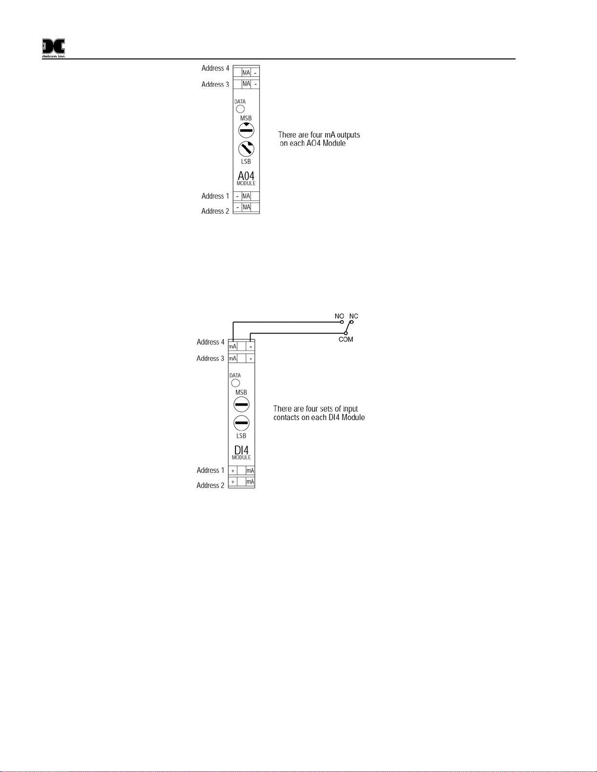
4-20mA Output Modules
There are four 4-20mA outputs in each Model AO-4 module. These can be used as signal inputs to other
control devices. Connect to the AO-4 modules as shown in
1600/6400-N1P- Instruction Manual Rev. 1.1 Page 7 of 38
Figure 10:
1600/6400-N1P
Figure 10 Model AO-4 Module
Contact Input Modules
There are four addressable contact inputs in each DI-4 Module. The Module is powered by 24VDC, and the
voltage is used to produce a 4mA level when the contacts are open and a 20mA level when the contacts are
closed.
Figure 11 Model DI-4 Module
General Wiring Notes:
When I/O Modules are located at a remote distance from the controller, an end of line terminating resistor
is required to enhance communications reliability. Identify the last I/O Module in the loop, and open the
module casing using the clip release points. Locate and install the jumper on JP6. This adds a 120Ω
resistor to the end of the line. If applicable, add a 120Ω resistor to the last Modbus™ gas sensor.
Follow generally accepted guidelines for RS-485 serial networks. Do not wire I/O Modules and/or
Modbus™ gas sensors in long-distance ‘T-Tap’ configurations. Stay with direct serial configurations. See
Section
14.0 Appendix for serial communications configuration guidelines.
Use Detcon Recommended cabling whenever possible.
• Belden P/N 1502P cable is recommended for a single cable providing serial communications and
power.
• Belden 9841 cable is recommended for a single cable providing serial communications only.
Ground the cable shielding at the Model 1600/6400-N1P Controller only. Other points of grounding may
cause a ground loop, and induce unwanted noise on the RS-485 line, which in turn may disrupt
communications.
1600/6400-N1P- Instruction Manual Rev. 1.1 Page 8 of 38

1600/6400-N1P
4.0 Start-Up
4.1 Applying Power
Before applying power, make sure that all I/O Modules are correctly installed and that all wiring connections
between I/O modules and external devices are made correctly.
NOTE: Applying power with devices hooked up incorrectly may cause damage.
Turn the applicable AC Breaker and DC Breaker switches to the ON positions. Verify that the main touchscreen LCD comes up displaying gas readings on the display. After 5 seconds, verify that all the I/O modules
are being polled by observing a sequence of blinking LED’s on the I/O Modules representing successful serial
communication. Enter and exit the “Program Menu” to bring the Main Display quickly up to date after power
boot-up.
Figure 12 Power In
NOTE: The polling of the input devices takes place more frequently than the communications to the relay
output devices. The sequence of polling communication will follow the order of the I/O device switch
addresses.
4.2 Setting Device Identification on the I/O Modules
NOTE: If your Model 1600/6400 controller has been configured at Detcon, you may elect to skip to the
Operator Interface (Section
For a unit that has not been properly configured, the I/O modules must be serially addressed to establish
correct communications. Typically, the I/O modules will be identified from 01 to FF starting from the module
on the right hand side of the stack. The I/O module’s identification is established by setting the two rotary
switches to the correspondingly correct position. The top rotary switch sets the most significant bit (MSB).
The bottom rotary switch sets the least significant bit (LSB). For an address of 01, set the top switch to 0 and
the bottom switch to 1. See
NOTE: All addresses must be unique. There can be no duplication of addresses or failure to
communicate will occur.
NOTE: Not all I/O modules communicate on every polling pass. Input modules are polled more often
than output modules.
5.0) for further review of system operation.
14.2 Hexadecimal Table for Decimal to Hexadecimal conversion.
1600/6400-N1P- Instruction Manual Rev. 1.1 Page 9 of 38
 Loading...