

Page 1

C-199
PN 161872
REVISION H
4/2009
LCC/LCD2-14PT-3
PASS-THROUGH SERIES
WITH PROTOCOL
PLUS
INSTRUCTION MANUAL
™
Page 2

NOTICE
Users of this equipment must comply with operating procedures and training of
operation personnel as required by the Occupational Safety and Health Act (OSHA) of
1970, Section 6 and relevant safety standards, as well as other safety rules and
regulations of state and local governments. Refer to the relevant safety standards in
OSHA and National Fire Protection Association (NFPA), section 86 of 1990.
CAUTION
Setup and maintenance of the equipment should be performed by qualified personnel
who are experienced in handling all facets of this type of system. Improper setup and
operation of this equipment could cause an explosion that may result in equipment
damage, personal injury or possible death.
Dear Customer,
Thank you for choosing Despatch Industries. We appreciate the
opportunity to work with you and to meet your heat processing needs. We
believe that you have selected the finest equipment available in the heat
processing industry.
At Despatch, our service does not end after the purchase and delivery of
our equipment. For this reason we have created the Service Products
Division within Despatch. The Service Products Division features our
Response Center for customer service. The Response Center will direct
and track your service call to ensure satisfaction.
Whenever you need service or replacement parts, contact the Response
Center at 1-800-473-7373: FAX 952-469-4513.
Sincerely,
Despatch Industries
Page 3
Page 4
Page 5
Page 6

ii
Page 7

iii
WARNING: Failure to heed
warnings in this instruction
manual and on the oven
could result in personal
injury, property damage or
death.
NOTE: Read the entire
INTRODUCTION and
THEORY OF OPERATION
before installing the oven.
PREFACE
This manual is your guide to the Despatch
LCC/LCD2-14PT-3 SERIES pass-through ovens. It is
organized to give you the information you need quickly
and easily.
The INTRODUCTION section provides an overview of
the oven.
The OVEN OPERATION section details the function and operation of assemblies and
subassemblies on the oven.
The INSTRUCTIONS section provides directions on unpacking, installing, operating and
maintaining the oven.
An efficient way to learn about the oven would be to read the manual while working with
the corresponding oven control system. This will give you practical hands-on
experience with information in the manual and the oven.
Before operating the equipment, be sure you
understand all of the technical information contained in
this manual. Information skipped, not understood or
misunderstood could create the possibility of operating
the equipment in an unsafe manner. This can cause
damage to the oven or personnel or reduce the
efficiency of the equipment.
Page 8

iv
Revision A (6-02): Initial Creation
Revision B (11-02): Update drawings, add line connection detail.
Revision C (9-03): Update drawings.
Revision D (1-04): Update to software revision 4.0
Revision E (8-06): Revised Protocol Plus numbers. Updated Despatch address.
Updated CE documents
Revision F (4-07): Updated Set-up to include water cooling installation.
Revision G (11-07): Updated warranty
Revision H (4-09): Updated Controller Instructions
Page 9

v
TABLE OF CONTENTS
PREFACE ....................................................................................................................... iii
INTRODUCTION ............................................................................................................. 1
Features ...................................................................................................................... 2
Options ........................................................................................................................ 2
SPECIFICATIONS .......................................................................................................... 3
Electrical Specifications ............................................................................................... 3
Physical Specifications ................................................................................................ 4
Functional Specifications ............................................................................................. 4
INSTRUCTIONS ............................................................................................................. 5
Unpacking and Inspection ........................................................................................... 5
Set-up .......................................................................................................................... 6
Wiring .......................................................................................................................... 8
HEPA Filter Installation ................................................................................................ 9
HEPA Filter Burn-off ............................................................................................... 10
Filter High Limit ...................................................................................................... 12
OVEN OPERATION ...................................................................................................... 13
Oven .......................................................................................................................... 13
System Control .......................................................................................................... 14
HEPA Filters .............................................................................................................. 17
HEPA Filter Validation Testing ............................................................................... 18
Filter Unit Replacement .......................................................................................... 19
HEPA Filter / Magnehelic Pressure Gauge ............................................................ 20
HEPA Filter Preventative Maintenance Table ............................................................ 20
OPERATING ................................................................................................................. 21
Loading the Oven ...................................................................................................... 21
Pre-Startup Checklist ................................................................................................. 22
Operating Procedure ................................................................................................. 23
Starting the Oven ................................................................................................... 23
Sequence of Operation (system using Beacon Light) ............................................ 24
High Limit Alarm with Alarm Silence ...................................................................... 25
Maintenance .............................................................................................................. 26
Checklist ................................................................................................................ 26
Lubrication ............................................................................................................. 26
PROTOCOL PLUS CONTROL ..................................................................................... 27
Theory of Control Operation ...................................................................................... 27
Operating Modes .................................................................................................... 29
Setup Mode ............................................................................................................ 29
Fast Start Mode ...................................................................................................... 29
High Limit ............................................................................................................... 30
Indicators ............................................................................................................... 30
Displays ................................................................................................................. 31
Key Functions ........................................................................................................ 31
Outputs .................................................................................................................. 32
Relay (Continued) .................................................................................................. 33
Page 10

vi
Communication ...................................................................................................... 33
Optional Software ................................................................................................... 33
INSTRUCTIONS ........................................................................................................... 34
Start-Up ................................................................................................ ..................... 34
Operation ................................................................................................................... 35
Manual Mode ......................................................................................................... 35
Timer Mode ............................................................................................................ 36
Profile Mode ........................................................................................................... 37
Auto Start Mode ..................................................................................................... 37
Setup Mode ............................................................................................................ 38
Instructions for Setup Mode Pages ............................................................................ 39
Program Page ........................................................................................................ 39
Sample Profile ........................................................................................................ 42
Auto Start Page ...................................................................................................... 43
PID Page ................................................................................................................ 45
Control Page .......................................................................................................... 46
Communication Page (optional) ............................................................................. 47
Real Time Clock Page ........................................................................................... 47
Relay Outputs Page (optional) ............................................................................... 48
Test Page ............................................................................................................... 49
Zone Calibration Page ........................................................................................... 50
Sensor Calibration Page ........................................................................................ 52
Enable Page .......................................................................................................... 55
Digital Inputs (optional) .......................................................................................... 56
Error Messages and Alarms ...................................................................................... 57
Quick Reference and Default Values ......................................................................... 58
Technical Specifications ............................................................................................ 65
APPENDIX: DRAWINGS .............................................................................................. 66
Page 11

1
Atmosphere
Max Temp C
Model
Air
260
LCC2-14PT-3
Air
350
LCD2-14PT-3
INTRODUCTION
The LCC/LCD2-14PT-3 SERIES pass-through oven is equipped with sterile and nonsterile doors, for clean room operation. Safety interlock switches on each door prevents
both doors to open at the same time (these may be manually overridden if required).
The operator loads the product from the non-sterile side, and selects the program to
run. At the end of the process, the product is unloaded from the sterile side.
The LCC/LCD2-14PT-3 SERIES pass-through oven offers HEPA filtration for processes
where minimization of contamination is essential. The removable HEPA (High Efficiency
Particulate Air) filter is designed to provide a constant flow of 99.97% clean air to the
product being heated. The HEPA filter with silicone seal provides 99.99% filtration prior
to filter burnoff. A magnehelic differential pressure gauge monitors pressure drop
across the HEPA filter.
The LCC2-14PT-3 Series ovens are rated up to 260 C, and the LCD2-14PT-3 Series
has a maximum temperature of 350 C.
The voltages available are 208V, 240V, 415V, and 480V,
3 Phase; with a 16kW heater.
The oven’s main operator interface components are on the hinged control panel located
on the non-sterile side. The power components; fuse blocks and motor starters are
located on the equipment panel, behind the hinged control panel for easy access. The
transformer and the heater SSR’s are located in the lower compartment with the
recirculation and exhaust/cooling motors. An EMO (emergency off) switch, and
indicator lights showing what step the process is in, is located on the sterile side control
panel. Electrical components are either touch-proof or are shielded with Lexan to
prevent accidental exposure during maintenance and troubleshooting.
The optional Despatch Protocol Manager software is used to enable customer PC
control of an oven. Despatch Protocol Plus controllers may be networked together with
a Modbus communication option when multiple ovens are operated.
Page 12

2
Features
Despatch Protocol Plus microprocessor-based digital programmable control, with
simultaneous digital readout of both setpoint and actual temperatures.
CE compliance, including yellow and red disconnect switch/EMO mounted in the
front control panel door.
Manual reset high-limit control.
Proportioning temperature control using solid state relays.
Four (4) inches of insulation minimizes heat loss, external thermal spots and air
leakage.
Stainless steel exterior and interior, with all interior seams continuously welded
on the insulation side to protect the work chamber from contamination.
Horizontal airflow, which achieves air temperature uniformity of +/- 1% of
operating temperature.
Recirculation motor is mounted in the machinery compartment underneath the
oven, providing convenient access.
Indicator lights on the sterile side showing cycle status, and alerting operator if
non-sterile door is open.
Electrical door lock switch on each door prevents operator from opening chamber
door when cycle is in process or having both doors open at the same time. Door
lock switch has manual override for authorized maintenance personnel to release
door in case of power failure.
Options
Beacon light option on control panel provides visual cycle process indication to
operator (red/amber/green)
High-limit alarm/alarm silence switch option
Recorder option
Modbus RS422/485 communications option to Protocol Plus controller
Page 13
3
VOLTS
AMPS
PHASE
HERTZ
HEATER
208
50.5
3
50/60
16 kW
240
44.5
3
50/60
16 kW
415
25.2
3
50
16 kW
480
22.2
3
60
16 kW
NOTE that this oven is not intended to process solvents or other volatile or
flammable materials. The oven’s forced exhaust is intended for cooling
purposes ONLY.
WARNING: Failure to heed warnings in this instruction manual and on the oven
could result in personal injury, property damage or death.
WARNING: Do not use any flammable solvent or other flammable material in this
oven. Do not process closed containers of any substance or liquid in this oven
because they may explode under heat.
WARNING: Do not use the oven in wet, corrosive or explosive atmospheres unless
this oven is specifically designed for a special atmosphere.
SPECIFICATIONS
Electrical Specifications
If your line voltage is much lower than the oven voltage rating, heat up time is
significantly longer and motors may overload or run hot. If your line voltage is higher
than the nameplate rating, the motors may run hot and draw excessive amps. If the line
voltage varies more than 10% from the oven voltage rating, some electrical components
such as relays, temperature controls, etc. may operate erratically. Power connection is
performed by the user.
Page 14
4
Physical Specifications
ENGLISH
METRIC
CHAMBER VOLUME
14 cubic feet
396 liters
INTERNAL
DIMENSIONS *
25.5” W x 26”D x 37” H
65 cm W x 66 cm D x 94 cm H
EXTERNAL
DIMENSIONS
48” W x 40 “ D x 71 “ H
122 cm W x 102 cm D X 180 cm
H
SHELF SUPPORTS
Quantity 11 on 3” centers
Quantity 11 on 7.6 cm centers
SHELF LOAD
CAPACITY
50 pounds
22.6 kg
CHAMBER LOAD
CAPACITY
400 pounds
181 kg
NET WEIGHT
955 pounds
433 kg
SHIPPING WEIGHT
1050 pounds
476 kg
RECIRCULATION
FAN
950 cfm
27 cmm
MODEL
ATMO-
SPHERE
OPERATING
RANGE
HEATING TIME TO TEMP
(minutes, w/no load)
COOLING TIME TO TEMP
(minutes, w/no load)
TEMPERATURE
UNIFORMITY AT
CONTROL
STABILITY
50-
100°C
50-
175°C
50-
260°C
50-
350°C
100-
65°C
175-
65°C
260-
65°C
350-
65°C
100°C
175°C
260°C
350°C
LCC/LCD
2-14 PT3
AIR
60°C - 260°C
3 9 15
35
41
82
95
117
±1°C
±2°C
±3°C
±3.5°C
±0.5°C
* Clear width reduced to 24” (61cm) by shelf supports.
Functional Specifications
1. Uniformity figures are based on a nine-point test conducted in an empty oven
with thermocouples positioned at 3” from walls, and after the oven temperature
has reached stabilization (typically 30 – 60 minutes). Uniformity can vary slightly
depending on unit and operating conditions.
2. Operating temperatures and cooling times are based on a 20°C ambient
temperature measured at the fresh air inlet.
3. Exhaust fan specification is 85 cfm.
Page 15

5
INSTRUCTIONS
The INSTRUCTIONS section provides directions on unpacking, installation, operation
and maintenance of the Despatch LCC/LCD2-14PT Series pass-through ovens.
Unpacking and Inspection
Remove all packing materials and thoroughly inspect the oven for damage of any kind
that could have occurred during shipment.
See whether the carton and plastic cover sheet inside carton are still in good
condition.
Look at all outside surfaces and corners of the oven for scratches and dents.
Check the oven controls and indicators for normal movement, bent shafts,
cracks, chips or missing parts such as knobs and lenses.
Check the door and latch for smooth operation. (Use a hollow point torx tip tool
and rotate 90 degrees counterclockwise the manual override in the safety switch.
It must be turned back to the locked position to allow electrical operation.)
Check the filter carton for damage.
If there is damage that could have happened during shipment follow these instructions:
1. Contact the shipper immediately and file a written damage claim.
2. Contact Despatch Industries to report your findings and to order replacement
parts for those that were damaged or missing. Please send a copy of your
filed damage claims to Despatch.
3. Check the packing list to make sure you have received all the specified
components of the oven system. If any items are missing, contact Despatch
Industries to have them forwarded to you.
4. Complete the warranty card and mail it to Despatch within 15 days after
receipt of the equipment.
Page 16

6
WARNING:
Do not use the oven in wet, corrosive or
explosive atmospheres unless this oven is
specifically designed for a special
atmosphere.
WARNING: Do not use any flammable solvent or other flammable material in this
oven. Do not process closed containers of any substance or liquid in this oven
because they may explode under heat.
Set-up
1. Select the location for installing
your oven.
2. Make sure the oven is level and
plumb; this will assure proper
heat distribution and operation
of all mechanical components.
3. This oven has been designed for use in a clean room environment (sterile and
non-sterile rooms).
4. The oven has a four (4) inch diameter exhaust opening and is located on the left
side of the oven. The oven may be placed next to another cabinet on its right, or
next to another oven, with three-quarters of an inch clearance (measure with
door open). Exhaust air may reach 260° C on the LCC version and 350° C on
the LCD version. Make sure exhaust piping materials can withstand these
temperatures.
5. (Water Cooled Models) Install water connection for cooling coils to the inlet
marked "Water Inlet." Verify the valve on the flow meter is turned off (fully
clockwise). The water supply to the oven must not exceed 100 PSI. It is
recommended to install a regulator to prevent any surge. Check for leaks. Slowly
open the valve on the flowmeter and allow any air to bleed out. Failure to do this
will result in damage to the flowmeter. Repeat this procedure if water supply is
shut off. Adjust the flowmeter to 3 gpm (recommended amount of flow).
6. (Water Cooled Models) Make the drain connection at the side of the oven. Note
there are two drain connections: water outlet and water drain. Note the water
outlet may be connected in a closed loop system, but the water drain must be left
in an open-to-atmosphere condition.
7. (Water Cooled Models) Connect the compressed air supply line to the inlet
marked “Dry Air”. The compressed air supply should run at 70 PSI but not more
than 80 PSI. Check for leaks.
Page 17
7
WARNING:
Never allow drain to be plugged as a hot oven will generate a small amount of steam
when the water is first turned on. STEAM BURNS!
CAUTION:
Design the drain system to prevent operator injury from high temperature or pressure
buildup. Piping must be able to withstand short periods of up to 650 °F (343 °C)
temperatures. Drain lines should be insulated and/or warning labels installed that a
hazard exists.
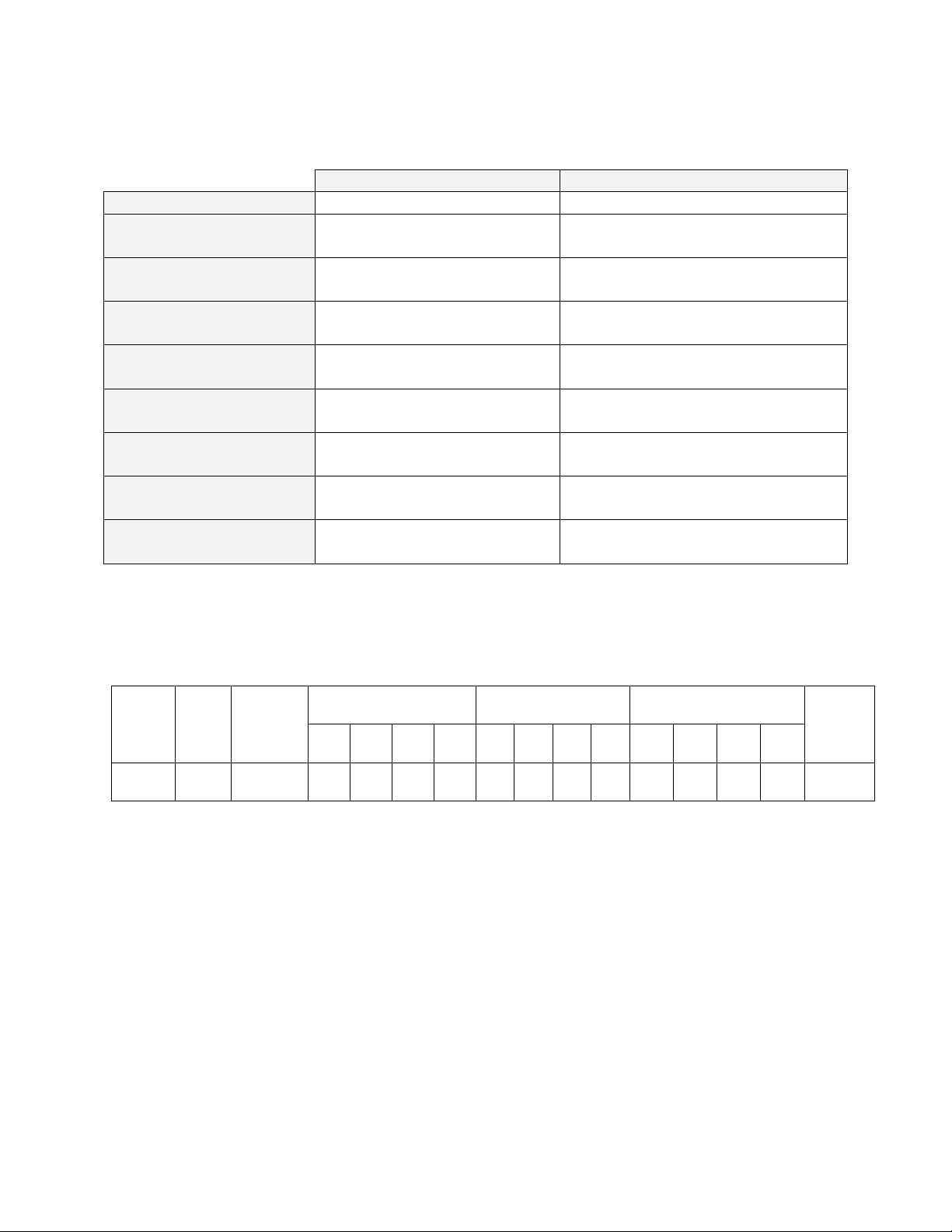
Clean Dry Air Inlet.
70 to 80 PSI (4.83 to
5.52 Bar).
Used to purge water
out of the coil prior to
heating the oven.
3/8” NPT female brass
connections are
provided.
During cooling cycle,
water flows through the
water coil and out this
connection.
3/8” NPT female brass
connections are provided.
Piping must be rated for
up to 257 F (125 C)
At the end of a cooling cycle,
Clean Dry Air is purged through
the water coil. Water and
pressurized nitrogen/air exit this
connection for 30 seconds.
Must be connected to gravity
style drain (no backpressure).
3/8” NPT female brass
connections are provided.
Piping must be rated for up to
257 F (125 C).
Water Inlet for cooling.
3/8” NPT female brass
connections are
provided.
Requires 3 GPM flow at
55 F (13 C) to meet
published cooling rates.
MAXIMUM PRESSURE
100 PSI (6.89 Bar)
LCC/LCD2-14-3 WITH WATER COOLING UTILITY
Page 18
8
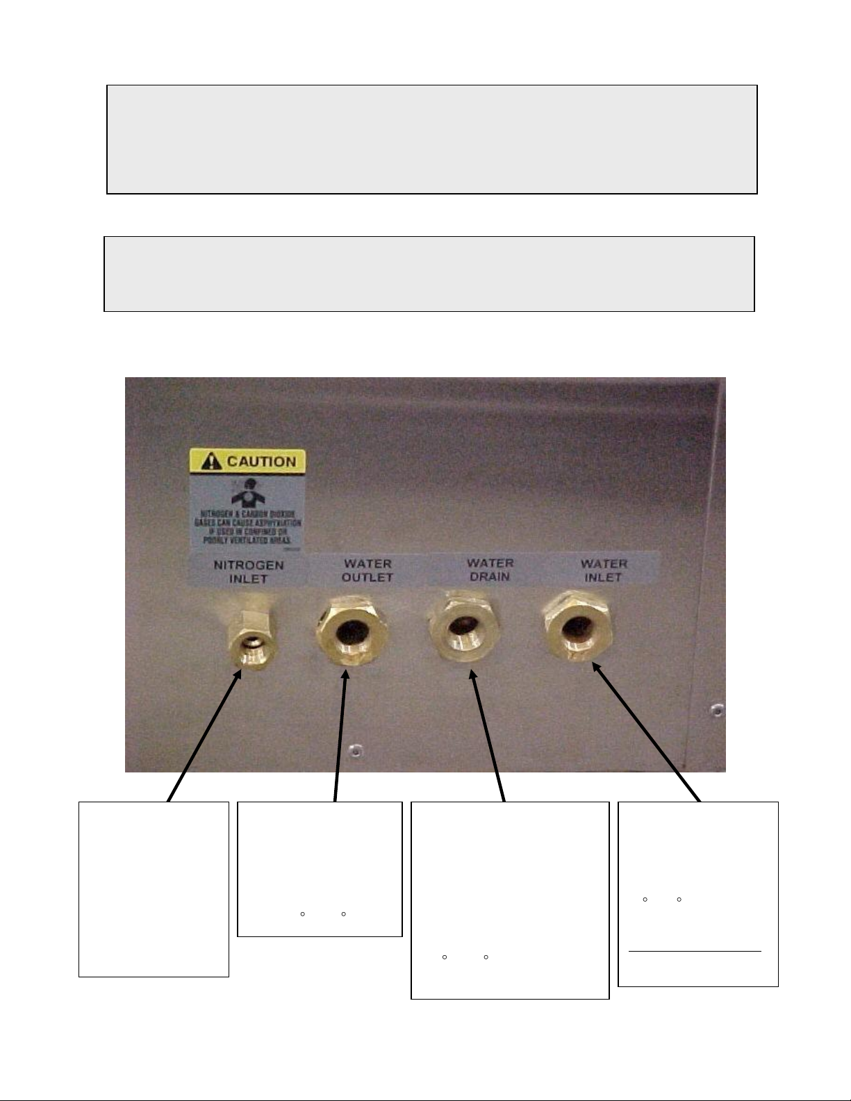
WARNING:
All grounding and safety equipment must be
in compliance with applicable codes,
ordinances and accepted safe practices.
Power wires are
connected to this
disconnect switch
and ground bus.
Approximately 84”
(2.13 meters) of wire
length is required
from the entrance on
left side of oven to
these connections.
Power wires are
routed through
this unused
conduit to main
equipment panel.
Power wires are
routed through this
compartment.
Hole for conduit
fitting provided
on side of oven
for customer
power.
Wiring
NOTE: The oven must be directly
hardwired to the disconnect switch
on the equipment panel. A one (1)
inch conduit run is provided from the
left side of the lower oven compartment
to the front equipment panel, through which the line voltage power wiring can be
connected to the disconnect switch labeled LINE CONNECTION in the front of panel.
Consult the electrical drawings included with the oven for wiring details. All wiring to be
completed by properly trained and licensed personnel.
LCC/LCD2-14-3 LINE CONNECTION DESCRIPTION (ALL SERIES)
Page 19

9
WARNING: Repairing the damaged filter unit, particularly the medium,
should not be attempted by the user. Any unit so repaired must be retested
to assure that hidden damage does not exist which will reduce filtering
efficiency. Repair and retest is uneconomical for most users.
WARNING: Make certain that power is disconnected from
the oven before removing or replacing the HEPA filter.
HEPA Filter Installation
Technicians responsible for installing the filter should use caution. The filter is delicate
and must not be damaged during installation. Any filter unit dropped, whether or not in
the carton, should be examined for damage. Equally important, the filter unit must be
installed so that unfiltered air will not leak past the unit.
1. Remove the filter from the carton.
a. Place the carton on the floor. The floor must be clear of nuts, bolts, and
similar protrusions, which would damage the face of the unit. Do not drop
or jar the carton.
b. Tilt the carton on one corner. Be sure to handle the carton at opposing
corners.
c. Remove the sealing tape and fold the flaps of the carton back.
d. Gently upend the filter to place the exposed end of the filter on the floor.
Do not jar the filter.
e. Pull the carton from the filter unit. Do not pull the filter from the carton.
2. Inspect the filter. Use a strong lamp to examine the exposed areas of both faces
to assure that no breaks, cracks, or pinholes are evident. A flashlight, can be
used in a darkened room.
Look for visible defects with the light projected along the full length of
each channel created by the separators. Translucent spots may not
necessarily indicate holes or cracks but may simply be variations in
thickness of the filter medium.
Check that the adhesive seal around the filter unit faces are complete
and unbroken.
Check the corner joints of the frame for adhesive sealing and
tightness.
Page 20

10
WARNING: Make certain that power is disconnected from
the oven before removing or replacing the HEPA filter.
Check that the gaskets are cemented firmly to the filter frame and that
the gasket pieces are butted or mated at the joints.
3. Pull the shelf out from the oven and set it aside.
4. Loosen the screws at the sides and top of the supply duct/shelf supports on the
right side of the chamber. Pull out the duct/shelf support and set it aside.
5. Remove the brass nuts and washers from the rods that are holding the filter
frame in place. These nuts will be reused to hold the filter in place.
6. Remove and discard the conduit spacers from the rods behind the filter frame.
Place the filter in the oven with the seal side towards the right side oven wall.
Reinstall the filter frame using the nuts removed earlier. Make sure the filter face
is tight against the inside perimeter of the frame on all sides.
7. Reinstall the brass nuts and washers to tighten the filter frame down. Tighten the
six nuts alternately for even tightness. Be careful not to over tighten. Correct
installation torque is 28 +/- 3 in-lbs. Be sure to compress the gasket evenly and
equally at all points with the filter frame completely covering the opening.
8. Reinstall the shelf support/duct assembly using the screws removed earlier.
9. Reinstall the oven shelf.
HEPA Filter Burn-off
The burn-off process will take place in any piece of equipment where a new HEPA filter
is used at temperatures above 180°C / 356°F. There will be smoke, possibly a pungent
odor, and a light residue on interior surfaces. This is the result of oxidation of the
binder. Most of the binder will leave the filter after running at a temperature of
260°C/500°F for 48 (forty-eight) hours. Check the oven for particles or the exhaust for
smoke and odor to determine that the process is finished.
Select a location for this process where the smoke and odor generated will be ventilated
with the least amount of interruption and inconvenience. Ideally this will be in the final
location for the oven. However, it may be a receiving dock, some well ventilated space
or even outside if the weather is acceptable. If this location is a very clean area, then
special attention must be given to an exhaust hook-up that will capture the smoke and
odor. The post-cleaning (i.e. oven wipe down) may also generate dust, and care should
be taken if this is done in a clean room.
Page 21

11
NOTE: If it is necessary to move the equipment after the burn-off process, considerable
care should be used. The binder which gives strength to new filters is now burned-off and
the media is very fragile. Rough handling of either the filter alone or the equipment with the
filter installed is not recommended as it may tear the media and lead to reduced filter
efficiency. Removal of the filter after heating can also result in damage to the frame seal,
and is only recommended when replacing the filter.
The following procedure is recommended:
1. Locate the equipment exhaust opening where chamber air is being expelled.
If the oven filter is burned off in a clean area, be sure to handle the equipment
exhaust appropriately. If the equipment is large and the exhaust stack is a
permanent service connection, it should be connected before the burn-off
process is run. If the equipment is small with no permanent exhaust duct
required, arrange a temporary connection out of the clean area that will handle
the maximum temperature of the equipment. Direct the smoke and odor outside,
or to a highly ventilated area.
2. Set the temperature control at the maximum process temperature.
Silicone: Ramp at 1.25°C/min to 260°C and soak for 48 hours.
Media Pack: Ramp at 1.25°C/min to 260°C and soak for 48 hours.
Termikfil: Ramp at 5°C/min to 350°C and soak for 48 hours.
3. Start the fan after making the electrical power connections.
4. Energize the equipment heater.
Use enough fresh air to remove the smoke, while still being able to achieve and
maintain the necessary temperature. The completion of the burn-off period
should be based on the particle level in the oven or smoke-free exhaust and
minimal odor level.
The filter hold-down nuts should be checked after burn-off and tightened again if
necessary. For best oven particle control, this step should be repeated on a
regular basis.
Page 22
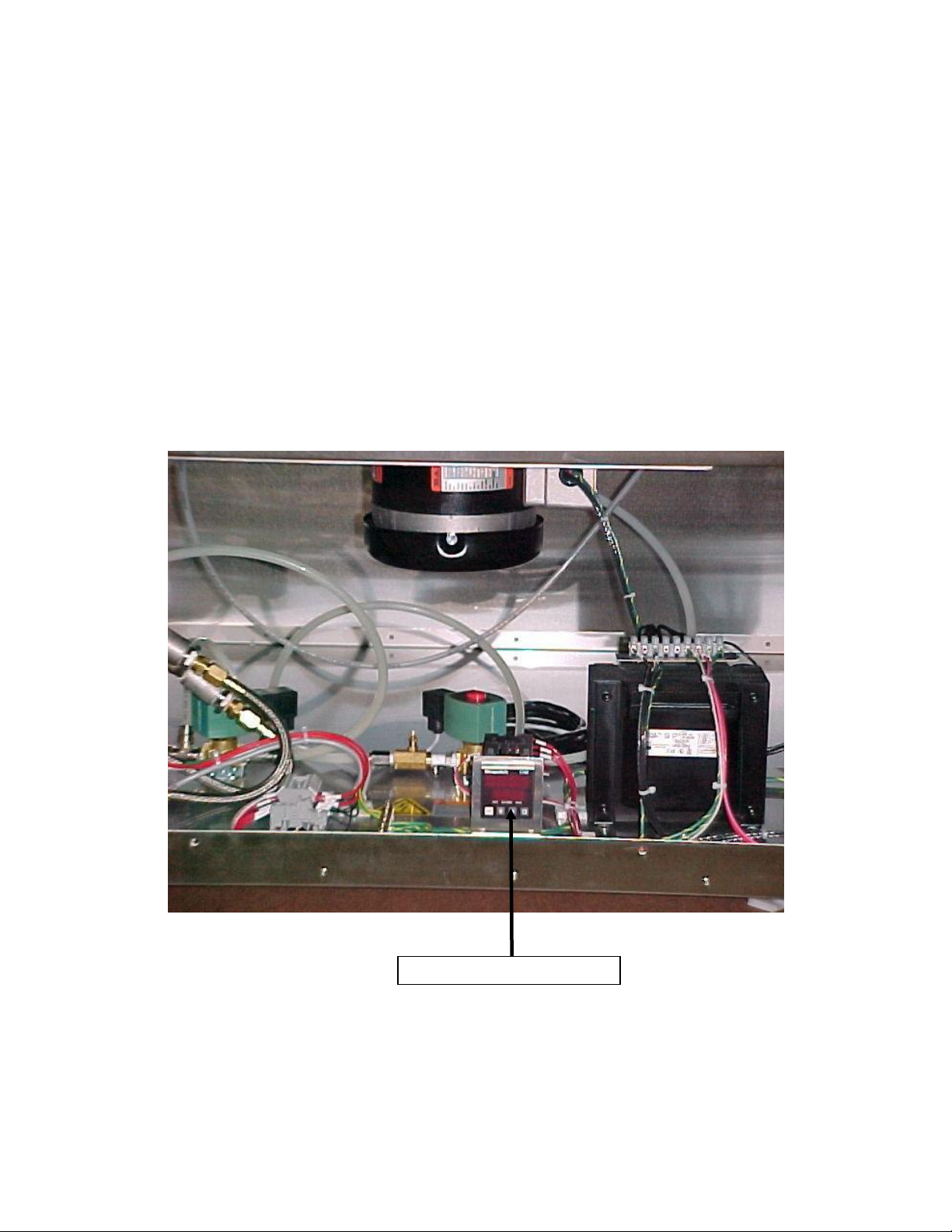
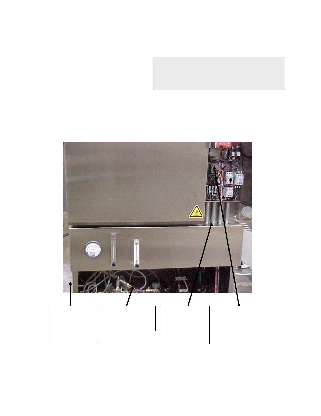
12
LCC2-14 HEPA High Limit
Filter High Limit
The LCC/D2-14*-3 series ovens have been equipped with a redundant high limit device
to protect the HEPA filter. The sensor for the high limit is located before the air inlet of
the HEPA filter. The high limit device is located in the lower compartment of the oven.
If the oven temperature exceeds the factory set Filter High Limit temperature, the high
limit will trip, shutting down the heater and protecting the HEPA filter.
Before resetting the high limit, determine the cause of the excessive temperature.
Under normal operating conditions the Filter High Limit should never trip. If the high
limit trips, it must be reset by removing the access panel to the lower compartment. The
high limit is located next to the transformer; press the reset button on the high limit. See
the MIC1162 reference manual for the operation of this high limit.
Page 23

13
OVEN OPERATION
Oven
The LCC/LCD2-14PT-3 Series pass-through oven is a class 100 clean room oven with
HEPA (High Efficiency Particulate Air) filtration. This oven is ideal for processes where
minimization of contamination is essential.
Forced convected airflow provides rapid uniform distribution of heat. A HEPA (High
Efficiency Particulate Air) filter is mounted in a stainless steel frame in the supply
plenum. These filters are 99.97% effective in filtering 0.3 micron particles prior to filter
burn-off.
The cooling/exhaust fan is controlled on/off by an event relay in the Protocol Plus
Control. The cooling fan is used for rapid cool-down at the end of the process cycle, or
to maintain low temperature setpoints during process cycle. It may also be turned on at
the start of a process cycle to assure that starting temperature is less than 70°C.
The oven has a type 304-2B stainless steel interior. All interior seams are continuously
welded on the insulation side. This protects the work chamber from contaminated air
and permits chamber washing without damaging the insulation. Interior ductwork may
be easily removed for cleaning. Heater frame, fan wheel and motor shaft are
constructed of stainless steel.
Non-sterile side controls are mounted on the front of the oven for easy operation and
readability. The EMO (emergency off) switch and indicator lights are mounted on the
control panel on the sterile side. Two electropolished stainless steel wire shelves are
provided. The shelves are removable and adjustable on three inch centers.
Page 24
14
System Control
A Despatch Protocol Plus controller/high-limit device is used to control the unit. This is
located on the control panel of the oven. See the section on the Protocol Plus controller
for detailed operation.
The Protocol Plus controller provides temperature control for the process.
The Protocol Plus controller provides outputs for the cooling/exhaust fan, and
door lock switch/door release pushbuttons.
As many as eight (8) profiles for oven heating cycles are stored in the Protocol
Plus controller. These are accessed by the operator using the Protocol Plus
keypad.
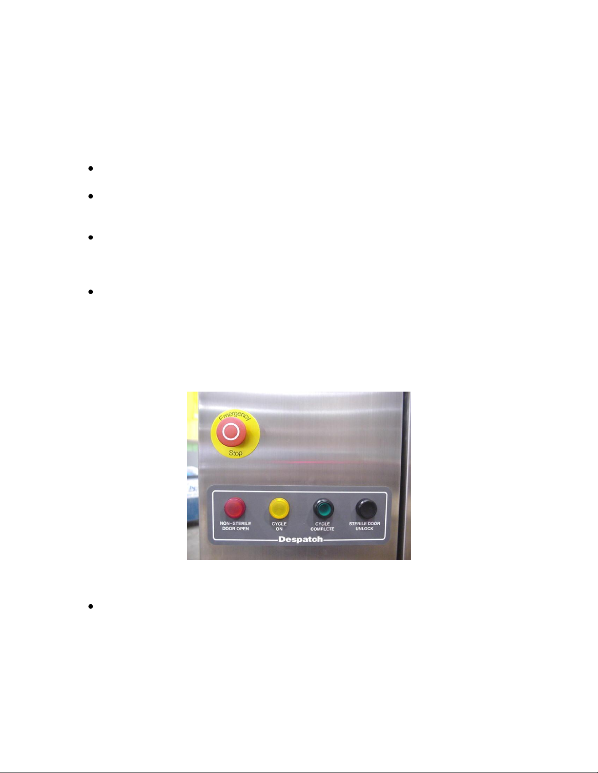
Indicator lights on the sterile side provides visual indication of the cycle status, as
follows:
Red (pilot light) – Non-Sterile Door Open
Yellow (pilot light) – Cycle On
Green (illuminated push button) – Cycle Complete (depress push button after
unloading and sterile door closed)
Indicator Lights
Optional MODBUS RS422/485 serial communications hardware may be installed
on the Protocol Plus controller, with two 9-pin communications ports located on
the front of the oven. This provides the ability to network the oven(s) with a host
PC.
Page 25

15
The optional three-color beacon light on the non-sterile side provides visual
indication of the cycle status, as follows:
Green – Cycle in process
Yellow – Standby. Operator has unloaded product. Oven waiting for next
cycle.
Red – Error or fault condition.
The optional High-Limit Alarm indicates when the high-limit setpoint has been
exceeded. An illuminated Alarm Silence push-button lets the operator turn off
the alarm while providing a red warning light until the high-limit condition is
corrected.
Page 26

16
Main
Disconnect
Switch
Door Release
Pushbutton
Power
START/STOP
Switch
Secondary
Chamber Lock
Door Unlock
Upper Portion of Control Panel (optional beacon light installed)
Lower Portion of Control Panel (Need New)
Manual Unlock: In the event of power failure, a hollow-point torx tip tool (provided) may
be inserted and rotated 90 degrees counterclockwise to allow the chamber door to
open. It must be turned back to the locked position to allow electrical operation again.
Main Disconnect Switch: This disconnect switch is connected to the load break switch
behind the panel that disconnects or connects power from the main line.
Page 27

17
HEPA Filters
HEPA (High Efficiency Particulate Air) filters are used to limit particulate size in the work
chamber to 0.3 microns or less.
NOTE: Chamber temperature transitions must not exceed 1.25°C/minute in order to
maintain class 100 chamber conditions. An optional filter is available for transition rates
up to 5°C/minute. Consult factory.
Definitions
HEPA - High Efficiency Particulate Air
Burn-Off - A process for getting rid of the binder contained in the filter.
D.O.P. - Dioctyl Phthalate - Aerosol particles of submicron size used in the testing
phase to spot defects or measure filter efficiency. Despatch Industries DOES NOT
RECOMMEND use of this or other organic challenge agents.
Binder - An organic substance that is used in the construction of the filter that gives
some structural strength to the media.
Filter Packaging and Shipping
Packaging practice varies among the filter unit manufacturers. Normally units are
packaged in cardboard cartons with various approaches for internal strengthening and
impact-resistance of the container. The shipping carton normally is marked with a
vertical arrow and "This Side Up". A filter unit is placed in the carton so that the pleated
folds are vertical (running from top to bottom - not side to side).
Filters should be shipped, handled and stored with the pleats in the vertical position. If
shipped with the pleats in the horizontal position, the filter medium may break at the
adhesive line. If handled or stored with the pleats in the horizontal position the pleats
may sag.
Moreover, the filter unit should be installed with the pleats in the vertical position. When
installed in the horizontal position the pleats form shelves for the collection of entrapped
material. The accumulated weight of this material causes sagging and leads to an early
failure of the unit.
Page 28

18
Handling
The filter is shipped in the original carton or package that the filter manufacturer uses.
This will give good storage and maximum protection from dirt and moisture.
HEPA filters should be stored and moved in the shipping carton with in the upright
position. Handling should be kept to a minimum. During installation the filter should be
removed from the shipping carton and installed directly into the oven.
If for any reason an unpackaged filter unit must be placed with its face on the floor or
other surface, the surface must be cleared of every object or irregularity, which might
damage the filter pack.
HEPA Filter Validation Testing
This section describes the Despatch position and recommendations for HEPA filter
testing and oven validation procedures. Despatch guarantees that the filters will meet
specified efficiency ratings when the filter is:
properly installed
run at or below 180°C, at a constant temperature
burned off at 260°C for 48 hours before running
D.O.P. Testing
In D.O.P. testing, aerosol particles of submicron size are used to spot defects or
measure filter efficiency. Degenerative by-products of this test are distributed
throughout the oven chamber upon heat-up. These and other organic challenge agents
also present a fire hazard for this non-Class A (NFPA 86) oven. Therefore Despatch
does not recommend D.O.P. filter testing.
Class 100 Testing
Despatch guarantees the environment within the oven to be Class 100. This
classification is based upon measurement of the particulate level within the oven work
chamber.
Class 100 testing may be performed before or after a proper filter burn-off procedure
has been performed. Despatch will guarantee Class 100 conditions measurements
based on the direct method of test employing an extraction-type particulate analyzer.
An indirect method of testing involves particle settling over a specified period of time
onto a clean disk. Please consult the factory for expected levels.
Page 29

19
Validation Testing
Based on the issues discussed in this section, Despatch recommends the following test
sequence for pharmaceutical Class 100 ovens.
1. Proper installation of the HEPA filters.
2. Ambient air challenge to determine integrity of oven chamber and filter gaskets.
3. Proper filter burn-off procedure.
4. Class 100 testing inside the work chamber.
The Necessity of the Burn-off Process
HEPA filters contain a binder material, which protects the filter media during production
and shipping. This smoke is typically not desirable during normal operation of the oven.
Burning off the binder will ensure a clean process at elevated temperatures.
When the binder is burned off of the filter media, the filter becomes very fragile, too
fragile to withstand normal shipping and handling. For this reason, Despatch does not
perform the burn-off procedure. The burn-off process is not necessary at process
temperatures consistently under 180°C.
Filter Unit Replacement
Replacement of the filter unit is necessary for these reasons:
Resistance, or pressure drop, across the filter unit. Maximum level of resistance
in inches (water gauge) will vary depending upon the operation of the filter and
the available fan capacity. Adequate fan capacity must be available.
Loss of efficiency (leakage), determined from air-sampling measurements made
downstream of the filter unit.
Visible damage or rupture of the filter media in a unit.
Change in process application.
Excessive build-up of lint or combustible particulate matter on the filter unit.
Water droplets in airstream through filter, free water (RH = 100%), will saturate
filter very quickly and may cause burnout or holes in burned off filter media.
Page 30

20
A
B
C
D
Date
Comments
Pressure
(inches of
water)
Oven
Temperature
Typical Values
2-3 inches
60°C
Filter first installed.
HEPA Filter / Magnehelic Pressure Gauge
The LCC Series oven is equipped with a Magnehelic pressure gauge which measures
the pressure in front of the HEPA filter. As the filter becomes dirty, the pressure will
increase. Despatch recommends changing the filter when the pressure is 1” w.c.
greater than when the filter was first installed.
Since the pressure can be affected by many factors involved in the installation, it is
important to record the pressure of a new filter, so that the pressure readings can be
periodically checked against this baseline. The table below is provided for recording
this information.
HEPA Filter Preventative Maintenance Table
Page 31

21
WARNING: Do not use
any flammable solvent or
other flammable material
in this oven. Do not
process closed containers
of any substance or liquid
in this oven because they
may explode under heat.
OPERATING
Users and operators of this oven must comply with operating procedures and training of
operating personnel as required by the Occupational Safety and Health Act (OSHA) of
1970, Section 5 and relevant safety standards, and other safety rules and regulations of
state and local governments. Refer to the relevant OSHA and National Fire Protection
Association (NFPA) safety standards.
Loading the Oven
Despatch Industries cannot be responsible for either the process or process
temperature used, or for the quality of the product being processed. It is the
responsibility of the purchaser and operator to see that the product undergoing
processing in a Despatch oven is adequately protected from damage.
Carefully following the instructions in this manual will
help the purchaser and operator in fulfilling that
responsibility.
When loading the oven avoid spills of anything onto
the heater elements or onto the floor of the oven. Do
not place the load on the oven floor plate. This may
cause the load to heat unevenly and the weight may
cause shorting out of the heater elements. Use the
shelves provided.
The two shelves are designed to be pulled out about halfway without tipping. Do not
overload the shelves.
Distribute the workload evenly so that airflow is not restricted. Do not overfill your oven.
The workload should not take up more than two-thirds of any dimension of the inside
cavity.
Page 32

22
WARNING: Do not use
any flammable solvent or
other flammable material
in this oven. Do not
process closed containers
of any substance or liquid
in this oven because they
may explode under heat.
Pre-Startup Checklist
Know the system. Read this manual carefully.
Make use of its instructions and explanations.
The know how of safe, continuous, satisfactory,
trouble-free operation depends primarily on the
degree of your understanding of the system and
of your willingness to keep all parts in proper
operating condition.
Check line voltage. This must correspond to nameplate requirements of motors
and controls. A wrong voltage can result in serious damage. Refer to the
section on power connections in the INTRODUCTION of this manual.
Check fresh air and exhaust dampers. Do not be careless about restrictions in
and around the fresh air and exhaust openings and stacks. Under no condition,
permit them to become so filled with dirt that they reduce airflow.
Page 33

23
Operating Procedure
Starting the Oven
1. Turn the yellow/red DISCONNECT SWITCH to ON.
2. Press the POWER pushbutton ON switch.
The green CYCLE COMPLETE illuminated push button will be lit (sterile
side). If required, the sterile door may be opened (non-sterile door will be
locked); otherwise, depress the CYCLE COMPLETE illuminated push
button. This will reset the oven, indicating oven is ready for new process.
To open the oven door, press the STERILE DOOR UNLOCK pushbutton
and at the same time, press on the door. The oven door will unlatch and
open.
(optional beacon light-equipped units) The amber (center) beacon light will
illuminate, indicating that the oven is waiting for new process to start.
3. The non-sterile DOOR RELEASE pushbutton will illuminate. This means the
door can be opened (sterile door will be locked).
(optional beacon light-equipped units) The amber (center) beacon light will
illuminate, indicating that the oven is ready to receive work to be
processed.
4. To open the oven door, press the DOOR RELEASE pushbutton and at the same
time, press on the door. The LED on the door lock switch will illuminate,
indicating the solenoid has been energized. The oven door will unlatch and
open.
5. NOTE: During the process cycle, both doors will remain locked. The door lock
switches has manual override for authorized maintenance personnel to release
door in case of power failure.
6. If the oven needs to be shut down in an emergency:
From the non-sterile side, turn the disconnect switch to OFF. Reset by
turning the disconnect switch back to ON. Go to step two (2) for restarting
oven.
From the sterile side, push the EMO switch in. Reset by pulling switch
out. Go to step two (2) for restarting oven.
Page 34

24
Sequence of Operation (system using Beacon Light)
This section describes operation of the oven with the optional beacon light feature.
1. After the system is powered up (see above procedure), the Protocol Plus
controller is initialized.
2. At this point the oven is idle, empty, door closed, and waiting for the next lot to be
processed. The Protocol Plus is not running a profile. The amber beacon light is
on steady for steps 2 through 5, until profile is started. Refer to the Protocol Plus
instructions in this manual.
3. Open the oven door. The red pilot light on the sterile side (STERILE DOOR
OPEN) is on.
4. Place the product on the shelf in the oven. Close the oven door. Red pilot light
on sterile side is off.
5. Run the desired profile from the Protocol Plus controller.
Press the Select key until Profile is displayed (you can press the Run key at
any time to activate Profile Mode).
Press the key to display the desired profile to run.
To start Profile Mode, press the Run key.
NOTE: The display will change from Stop to Run and the segment time
remaining, along with the current segment number, will be displayed.
6. The oven profile cycle is in process and both doors are LOCKED. The yellow
pilot light on the sterile side (CYCLE ON) is on. The green beacon light is on
steady, the amber beacon light is off.
7. When the process is complete, the green illuminated push button on the sterile
side (CYCLE COMPLETE) is on, and the amber beacon is on.
8. Press the STERILE DOOR UNLOCK pushbutton on the sterile side, and open
the oven door to remove the product workload.
9. The operator closes oven door and presses the green illuminated push button
(CYCLE COMPLETE) to complete the process cycle.
10. The yellow pilot light on the non-sterile side (DOOR RELEASE) is on, and the
amber beacon is on. The oven is ready for the next lot.
Page 35

25
High Limit Alarm with Alarm Silence
This option provides an audible and visual alarm when the temperature exceeds the
high limit setpoint on the control. The alarm horn is located on the right side of the
control panel door. On the front of the control panel door, there is an illuminated (red)
momentary push button switch to silence the alarm horn.
When the chamber temperature exceeds the high limit setting on the control, the heater
will shut down the Alarm Horn will sound and the red push button will illuminate. To
silence the alarm:
1. Depress the Alarm Silence push button.
The Alarm Horn will be silenced, but the red pilot light on the push
button will remain illuminated.
(optional beacon light-equipped units) The red (top) beacon light will
illuminate, indicating a fault has occurred.
2. When the high limit condition clears, press reset on the control. See the section
on the Protocol Plus controller for detailed operation.
3. The heater should be back on and the control should be functioning correctly.
The red pilot light will not be illuminated.
4. If the high limit trips repeatedly, identify the cause and correct the problem.
Page 36

26
WARNING:
Disconnect the main power switch
or power cord before attempting
any repair or adjustment.
Maintenance
Do not attempt any service on this oven before
opening the main power disconnect switch.
Checklist
Keep equipment clean. Gradual dirt accumulation retards airflow. A dirty oven
can result in unsatisfactory operation such as unbalanced temperature in the
work chamber, reduced heating capacity, reduced production, overheated
components, etc. Keep the walls, floor and ceiling of the oven work chamber
free of dirt and dust. Floating dust or accumulated dirt may produce
unsatisfactory work results. Keep all equipment accessible. Do not permit other
materials to be stored or piled against it.
Protect controls against excessive heat. This is particularly true of controls,
motors or other equipment containing electronic components. Temperatures
greater than 50°C (122°F) should be avoided.
Establish maintenance & checkup schedules. Do this promptly and follow the
schedules faithfully. Careful operation and maintenance will be more than paid
for in continuous, safe and economical operation.
Maintain equipment in good repair. Make repairs immediately. Delays may be
costly in added expense for labor and materials and in prolonged shut down.
Practice safety. Make it a prime policy to know what you are doing before you do
it. Make CAUTION, PATIENCE, and GOOD JUDGMENT the safety watchwords
for the operation of your oven.
Lubrication
Fan motor bearings are permanently lubricated. All door latches, hinges, door operating
mechanisms, bearing or wear surfaces should be lubricated to ensure easy operation.
Page 37

27
PROTOCOL PLUS CONTROL
The special features of the Protocol PlusTM control include:
PID tuning
Ramp/Soak programming of up to 64 segments
Segment looping and profile linking
Built-in manual reset high limit control
Built-in process timer
Dedicated LED display for process temperature
Multi-purpose two-line LCD display with backlight
Auto-tuning
Security access
Process temperature retransmission signal
Digital inputs for remote profile control
Real time clock
Optional relay outputs for events, alarms, or end-of-cycle signal
Optional RS232/RS422/RS485 MODBUS communications
Theory of Control Operation
The Protocol Plus is a modular microprocessor based digital temperature controller. The
Protocol Plus operates as a dual functioning controller/high limit instrument. The control
portion utilizes a time-proportioning voltage signal to control heating devices with
minimal temperature fluctuations.
The high limit portion protects the product and/or the oven from overheating. If the
product being processed has a critical high temperature limit, the high limit setpoint
should be set to a temperature somewhat below the temperature at which the product
could be damaged. If the product does not have a critical high temperature limit, the
high limit setpoint should be set 5 to 15 degrees higher than the maximum programmed
setpoint at which the oven will operate.
Page 38
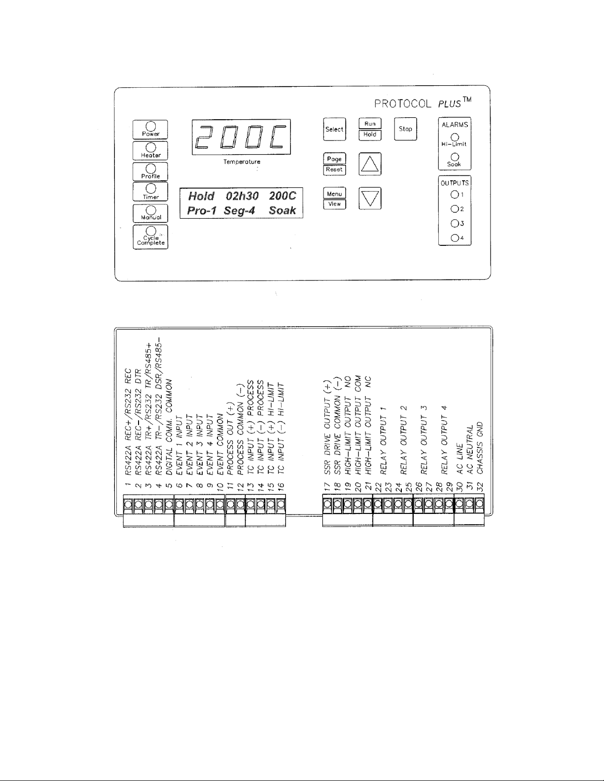
28
Protocol Plus Faceplate and Wiring Diagram
Page 39

29
Operating Modes
The Protocol Plus control has five modes of operation available:
Stopped Mode: All control and relay outputs are off. Stopped Mode is integrated
into each of the following four modes of operation.
Manual Mode: Control operates as a single setpoint control until Stopped mode is
accessed
Timer Mode: Control operates as a single setpoint control until preset time period
has expired.
Profile Mode: Control operates as a ramp/soak profiling control until the end of
the profile. 8 profiles are available with up to 8 ramp/soak segments
in each profile.
Auto Start Mode: Control may automatically start Manual, Timer, or Profile mode
based on a preset time and day.
The optional event outputs can be utilized during Manual, Timer, or Profile modes.
Setup Mode
The control has a Setup Mode which provides access to control configuration and
programming of profiles. The Setup Mode contains ten separate electronic Pages where
the configuration and programming parameters (Menu items) are found. The Setup
Mode Pages are described in detail elsewhere in this manual.
Fast Start Mode
The Protocol Plus control has the ability to automatically start an operating mode when
power is applied. This feature may be useful if the same mode of operation is used
everyday. The user can turn on the power and the oven will start the desired process
automatically. The Fast Start Mode is controlled by the Power-Up Start parameters on
the Control page (see Setup Mode).
Page 40

30
High Limit
The control has an integrated high limit function which will disable the heater output
when tripped. If the high limit does trip, the relay will need to be manually reset. When
the high limit relay is tripped, the Hi-Limit indicator will be lit. Allow the oven to cool
several degrees (or increase the high limit setpoint) and then press the Reset key. The
indicator will turn off.
High-Limit temperature readout is provided on LCD Line #2 in all Modes (Stop, Run,
Hold, and Standby) except Setup Mode. High-Limit temperature is displayed for 10
seconds, alternating with current Mode and Status display for 10 seconds.
The control will not allow the high limit setpoint to be set below the current setpoint
value.
Indicators
The Protocol Plus control has 12 indicating LEDs that provide operational information to
the user.
Power LED: Indicates that power is supplied to the instrument.
Heater LED: Indicates that the heater output is active.
Profile LED: Indicates that the Profile Mode is in operation.
Timer LED: Indicates that the Timer Mode is in operation.
Manual LED: Indicates that the Manual Mode is in operation.
Cycle Complete LED: Indicates that the control is in Stopped mode.
Hi-Limit Alarm LED: Indicates that the high limit relay has tripped
(de-energized).
Soak Alarm LED: Indicates that the guaranteed soak deviation is in alarm
condition.
Outputs 1 through 4: Indicate that the optional relay outputs are in the ON
state. These outputs may be configured as timed event outputs, process
temperature trip point outputs, alarm outputs, or as an end of cycle relay output.
The ON state can be configured as energized or de-energized.
Page 41

31
Displays
The Protocol Plus control has two displays. A dedicated LED upper display shows the
oven temperature. A two-line LCD lower display provides information on control status,
high limit temperature, and allows changes to be made to the control settings.
Key Functions
The Protocol Plus control has seven keys that provide operation.
Select key: Press to select mode of operation. In Setup Mode, to select profile
number or relay. In Profile/Run Mode, press simultaneously with the UP key to
advance a segment.
Run/Hold key: Press to activate a mode of operation. If a Profile (or Timer)
Mode is running, pressing the Run/Hold key will place the Profile (or Timer) in
Hold status. A subsequent press will resume the Profile (Timer).
Stop key: Press to stop any mode of operation.
Page/Reset key: While in Setup Mode, press to access different Pages of
configuration, Press this key to silence an alarm if the instrument alarm sounds
during operation. In an operating mode, if an alarm or error condition occurs,
press this key to return the instrument to normal operation once the condition is
cleared.
Menu/View key: While running any operating mode, pressing this key will
display the high limit setpoint. While in Setup Mode, pressing this key will provide
access to each Menu parameter.
keys: Press these keys to adjust parameter settings. In Profile/Stopped
Mode, press to select profile to run. In Profile/Run Mode, press key
simultaneously with the Select key to force the program to advance one
segment.
Page 42

32
Outputs
The Protocol Plus control has seven different outputs available.
Heating output: The control output is a DC voltage open-collector output which
is time-proportioned and designed to control a heat control device such as a solid
state relay.
High limit: The high limit output is a form C relay which is energized under
normal operating conditions. If the control senses a temperature higher than the
high limit setpoint, or if there is a sensor error, the high limit relay will de-energize
until the condition is cleared and the Reset key is pressed. When the high limit
relay is de-energized, the heater is disabled.
Retransmission: The retransmission output is a DC 1 to 5 volt or 4 to 20 ma
(DC) signal that is proportional to the process temperature. The signal can be an
input to other devices such as a chart recorder.
Relay (four optional outputs): The four form A dry contact relay outputs can be
configured to function as alarms, events, or end of cycle. These outputs can be
utilized in Manual, Timer, or Profile Mode.
Layout for Optional Components
Page 43

33
Relay (Continued)
Use the Relay Card Optional Ay p/n 144562 to add relays to the standard controller.
Each relay card contains two relays (maximum of two cards Ay’s allowed).
Communication
The Protocol Plus control has optional MODBUS communication available which can
communicate via RS232, RS422, or RS485 to a computer. See communications option
assembly p/n 161957 for board and cable assembly. Please refer to the MODBUS
communications manual which comes with this option.
Optional Software
The Protocol Manager program allows the operator to start/stop multiple ovens (32
maximum) from a personal computer. A data log can also be used to record process
information (p.n. 140008).
Page 44

34
INSTRUCTIONS
Start-Up
These instructions are provided as a quick reference for operating the Protocol Plus
control. If the Profile Mode is to be used, or the configuration of the control needs to be
changed, please refer to the Setup Mode instructions before operating the control. For
more detailed operating instructions refer to the Operation instructions for the mode you
wish to use.
Upon initial power-up the control is in Manual/Stopped Mode (unless the Autostart or
Fast Start Modes are active). To activate any operating mode from Stopped Mode,
press the Select key until the desired mode is displayed, then press the Run key. If the
proper Profile number is not displayed when the Profile Mode is accessed, press the
or keys until the desired Profile number is displayed, then press the Run key. If no
profile numbers can be displayed (display only reads NONE) then no profiles are
currently programmed (see Setup Mode).
The Hi-limit thermocouple actual temperature reading is displayed, when the lower LCD
display reads HL Temp. Note: This is not a error message.
The temperature setpoint can be adjusted while Manual or Timer Mode is running by
pressing the UP or DOWN key.
To momentarily hold the Timer or Profile Mode, press the Hold key. To continue the
Timer or Profile Mode, press the Run key.
To return to Stopped Mode at any time, press the Stop key and the cycle complete LED
will illuminate.
Note that the control can be configured to automatically activate Manual, Timer or
Profile Mode when power is applied (power switch turned on). See Control Page in the
Setup Mode to utilize the Fast Start mode.
Page 45

35
Operation
Manual Mode
Press the Select key until Manual is displayed (note you can press the Run key at any
time to activate Manual Mode).
1. Press the Menu key to display the Process Temperature Setpoint (setpt). You
can change the Setpoint with the keys.
Note: If the SPChange parameter on the Enable page in Setup Mode has been
set to DISABLED, it must be changed to ENABLED before any changes to the
process temperature and high limit setpoints can be made.
2. Press the Menu key a second time to display current high limit setpoint (Hi-Lim
SP). The value can be adjusted by pressing the keys. If Band is displayed,
the high limit band feature is activated (see Control page) and the high limit can
not be adjusted.
3. (optional feature) Press the Menu key a third time to display Event1. Press the
key to turn on the event or to turn off the event. Repeat for all events which
are enabled (up to 4).
4. To start Manual Mode, press the Run key.
The display will change from Stop to Run. To return to Stopped Mode, press the
Stop key. While in operation, the process setpoint can be adjusted by using the
keys to change the value while the mode is running. Pressing the Menu key
will display the High Limit Setpoint (HLSP) setting.
If changes to the high limit setpoint or event output configuration are needed, they must
be done from the stopped mode.
Page 46

36
Timer Mode
1. Press the Select key until Timer is displayed (note you can press the Run key at
any time to activate Timer Mode).
2. Press the Menu key to display the Process Temperature Setpoint (Setpt). You
can change the Setpoint with the keys.
Note that if the SPChange parameter on the Enable page in Setup Mode has
been set to DISABLED, it must be changed to ENABLED before any changes to
the process temperature and high limit setpoints can be made.
3. Press the Menu key a second time to display current high limit setpoint (Hi-lim
SP). The value can be adjusted by pressing the keys. If Band is displayed,
the high limit band feature is activated (see Control page) and the high limit can
not be adjusted.
4. Press the Menu key a third time to display Time Set. You can change the time
setting with the keys.
5. (optional feature) Press the Menu key a fourth time to display Event1. Press the
key to turn on the event or to turn off the event. Repeat for all events which
are enabled (up to 4).
6. Press the Menu key a fifth time to display the current guaranteed soak band
(TmrGuarSoak) value. If the process temperature deviates from the setpoint by
more than this value, the timer is placed in a hold condition. The timer continues
when the process temperature falls within range. Reference the Quick
Reference and Default Values section for available settings.
7. To start Timer Mode, press the Run key.
The display will change from Stop to Run and the time remaining will be
displayed. To return to Stopped Mode, press the Stop key. While in operation,
the process setpoint can be adjusted by using the keys to change the value
while the mode is running. Pressing the Menu key will display the High Limit
Setpoint.
Pressing the Run/Hold key while the Timer Mode is in operation will put the control in
Hold status. The Timer LED will flash to indicate the held status. Press the Run/Hold
key again to continue timing. The Timer LED will return to lit status.
Page 47

37
Profile Mode
1. Press the Select key until Profile is displayed. “None” may be displayed if a
profile has not been selected or no profiles entered.
2. Press the key to display the desired profile to run.
3. To start Profile Mode, press the Run key.
The display will change from Stop to Run and the segment time remaining,
Temperature Setpoint, Profile #, along with the current segment number, will be
displayed. To return to Stopped Mode, press the Stop key.
Pressing the Run/Hold key while the Profile Mode is in operation will put the control in
Hold status. Press the Run/Hold key again to continue the mode. The Profile LED will
flash to indicate the hold status.
To advance to the next segment while running a profile, press the Select and UP arrow
keys at the same time.
If Link To is set to Standby in the Program Page, at the End of Program/Profile,
1. Cycle Complete LED indication goes ON.
2. Controller beeps if End of Cycle beep is enabled.
3. Heater/control output keeps controlling oven temperature at last Soak setpoint.
4. All events programmed (if relay cards installed and programmed as an event) for
the last Soak Segment stays active.
Note that ramping down too fast may cause the high limit relay to trip unexpectedly if
the high limit band feature is used. This can be avoided by using a separate cooling
profile that does not utilized the high limit band and then jumping to that profile to
perform rapid cooling.
Auto Start Mode
The Auto Start Mode allows the control to start Manual, Timer, or Profile mode
automatically at a preset time and day. See the Auto Start Page in Setup Mode for the
time, day, and operating mode settings.
To activate the Auto Start Mode,
1. On Auto Start page, Enable is set to Yes.
2. LCD reads Active on line 1 in Auto Start Mode.
3. On Auto Start page Enable set to No, will deactivate Auto Start Mode.
Page 48

38
Note that once you activate Auto Start, you can continue to use all operating modes as
normal. If an operating mode is running at the time of a preset Auto Start function, and
Auto Start is activated, the existing operating mode will override the auto Start function
and the Auto Start will not turn on.
Note: All process Set to Run in Auto Start Mode must be at least one minute long for all
Run Modes (Manual, Timer, and Profile).
Setup Mode
Configuration of the control and programming of the ramp/soak profiles must be done in
the Setup Mode. To access Setup Mode, the control must first be in Stopped Mode.
1. Press the Select key until Setup is displayed.
2. Press the Page key and Security will be displayed.
3. Press the Menu key and Password will also be displayed. Use the keys to
enter the proper password.
4. Once the proper password is displayed, press the Page key twice to enter the
Setup Mode.
To exit Setup Mode, press and hold the Page key for three seconds.
The control has two levels of password-protected security. Level one provides access
only to those menu pages that are enabled on the Enable page. Level two provides
access to all menu pages, including the Enable page. The default security password
values are 1 for level one and 2 for level two.
If an improper password has been entered, the control will remain at the Security
display. To enter the proper password, press the Menu key. To exit Setup Mode, press
and hold the Page key for three seconds.
Mapping of the Setup Mode is provided in the following sections. To access each
parameter Page, which are described in detail in the following sections, press the Page
key until the desired page heading is displayed. Press the Menu key to access each
Menu parameter. Press the keys to change Menu parameter settings.
Refer to the Quick Reference and Default Values section for available settings for each
Menu parameter.
Press the Page key to continue with each Page, or press and hold the Page key for
three seconds to exit Setup Mode.
Page 49

39
Instructions for Setup Mode Pages
Program Page
Programming of the profiles is provided on the Program Page. Eight profiles are
available with up to eight ramp and soak segments per profile.
If the optional relay outputs are installed, they must be configured as alarms or events
on the Relay Outputs Page before they can be utilized. If configured as event outputs,
these relays can be used as time or temperature events.
When entering the Program Page, press the Select key to select the profile you wish to
enter/edit, then press the Menu key. The first parameter (Profile #, Segment 1, Ramp
Time) will display. Adjust the time value with the keys. Once the proper value is
displayed, press the Menu key to continue. Continue with the Menu key to adjust/view
each parameter.
If the ramp time value of the current segment is left at 0:00, the next press of the Menu
key will advance the control to the High Limit Setpoint parameter for that profile.
Continue entering / verifying all parameters until you get to the last parameter
(Guaranteed Soak Band). Once all parameters have been properly entered, press the
Page key to return to the top of the Profile Page. You can press the Select key to
enter/edit another profile, press the Page key to access another page, or press and hold
the Page key to exit Setup mode.
While editing any profile, pressing the Select key will advance the control to the time
value for the next segment, until the last segment has been reached. This allows faster
editing of the profile rather than pressing the Menu key to advance past each
parameter.
If Link To is set to Standby in the Program Page, at the End of Program/Profile,
1. Cycle Complete LED indication goes ON.
2. Controller beeps if End of Cycle beep is enabled.
3. Heater/control output keeps controlling oven temperature at last Soak setpoint.
4. All events programmed (if relay cards installed and programmed as an event)
for the last Soak Segment stays active.
To run a profile indefinitely, link the profile to itself.
Page 50

40
Menu Item
Display
Description
Ramp Time Seg 1
Pro-1 Seg-1 Ramp Time
Ramp time for segment 1 of profile
Event 1 Set Value*
Pro-1 Seg-1 Ramp Event 1
Event 1 setting for segment 1 ramp of profile
Event 2 Set Value*
Pro-1 Seg-1 Ramp Event 2
Event 2 setting for segment 1 ramp of profile
Event 3 Set Value*
Pro-1 Seg-1 Ramp Event 3
Event 3 setting for segment 1 ramp of profile
Event 4 Set Value*
Pro-1 Seg-1 Ramp Event 4
Event 4 setting for segment 1 ramp of profile
Soak Temp Seg 1
Pro-1 Seg 1 Soak Temp
Soak temperature for segment 1 of profile
Soak Time Seg 1
Pro-1 Seg 1 Soak Time
Soak time for segment 1 of profile
Event 1 Set Value*
Pro-1 Seg-1 Soak Event 1
Event 1 setting for segment 1 soak of profile
Event 2 Set Value*
Pro-1 Seg-1 Soak Event 2
Event 2 setting for segment 1 soak of profile
Event 3 Set Value*
Pro-1 Seg-1 Soak Event 3
Event 3 setting for segment 1 soak of profile
Event 4 Set Value*
Pro-1 Seg-1 Soak Event 4
Event 4 setting for segment 1 soak of profile
(repeat for segments 2-8, until ramp or soak time = 00:00)
High Limit Setpoint
Pro-1 Hi-Lim SP
High limit setpoint for profile**
Loop From
Pro-1 Loop From Seg
To start a loop action in a profile
Loop To
Pro-1 Loop To Seg
To end a loop action in a profile
Loop Count
Pro-1 Loop Number
Number of times to execute loop
Profile Link
Pro-1 Link To Pro
To jump from this profile to another
Guaranteed Soak
Pro-1 Guar Band
Guaranteed soak band for profile
See the definitions on the following pages for parameter ranges.
* only available if optional relay outputs are installed (repeat all for profiles 2-8)
** Set to Band to use the high limit band feature
Page 51

41
Profile #
There are eight profiles available.
Segment#
Recipe segments 1 through 8 may be programmed, each with its own
set of events, ramp and soak times, and soak temperature.
Ramp Time
The time required to ramp from one setpoint up to another setpoint.
Values between 0 and 99:59 are allowable. In the Protocol Plus
controller, the profile ramp and soak times are stored without units.
Units are set as either hours and minutes (HH:MM) or minutes and
seconds (MM:SS). The setpoint will automatically increment from the
actual temperature to the soak temperature.
EV1 through 4
From 1 to 4 events may be programmed into the ramp time portion of
each segment here. These typically involve actuating/disabling relays
to close/open valves or perform other relay-controlled functions.
NOTE: These will only actuate when the controller has the relay cards
installed and programmed for an event.
Soak Temp.
The temperature setpoint of a particular segment is entered here; it
can range from -18 to 540 degrees C (0 to 1000 degrees F).
Soak Time
The duration of soak is entered here; the value can range from 0 to
99:59.
EV1 through 4
From 1 to 4 events may be programmed into the soak portion of each
segment here. These typically involve actuating/disabling relays to
close/open valves or perform other relay-controlled functions. NOTE:
These will only actuate when the controller has the relay cards
installed and programmed for an event.
Hi Limit SP
The high limit setpoint may be entered here; if the temperature
exceeds this value, the hi-limit will alarm and shut off the heater.
Loop From
Values are No, Seg-1 to Seg-8.
Loop To
Values are No, Seg-1 to Seg-8.
Loop Number
Values are 0 - 99.
These values enable the operator to jump from a certain step to
another step of the recipe a preset number of times.
Profile Link
Values are STANDBY/STOP/HOLD/1 - 8. When the profile ends, the
profile can hold the temperature setpoint while keeping the events
active, turn the heater off, hold the temperature setpoint at the end of
the profile, or jump to another specified profile.
Guaranteed
Soak Band
If the process temperature deviates from the setpoint by more than
this value, the soak timer is placed in a hold condition. The timer
continues when the process temperature falls within range.
Page 52

42
Sample Profile
Seg-
ment
Ramp
Soak
Time
Events
Temp-
erature
Time
Events
1 2 3 4 1 2 3
4
1
01h00
100
01h00
2
02h00
50
00h01
3
00h00
4
5 6 7 8
High Limit Setpoint
115 Loop From Seg
No
Loop To Seg
No Loop Number
0
Link To Pro
No Guar Soak Band
10
Programming Table
Profile Number____1______ Profile Name__________
Page 53

43
Auto Start Page
The Auto Start Page can be configured to automatically start Manual, Timer or Profile
Mode at a specified time and day. Note that if Auto Start Enable is set to Yes in the
Setup Mode, the Auto Start feature is not turned on - it is available to the operator to be
activated in Stopped Mode.
To configure the Auto Start feature:
1. Access the Setup Mode.
2. Press the Page key until Auto Start is displayed.
3. Press the Menu key. If there is no change in the display, the controller may not
have the realtime clock option.
4. Set Auto Start Enable to Yes.
5. Using the Menu key, scroll through the options available and use the keys
to set the mode desired for each day of the week. You may select from Manual,
Timer, or Profile 1 through 8.
6. When the mode is set press the Menu key.
7. Enter the time of day you wish the mode to activate.
8. Continue through the rest of the week by pressing the Menu key, or press the
Page key when done.
One Auto Start mode can be set for each day of the week. Exit the Setup mode by
pressing and holding the Page key for three seconds. Press the Select key until Auto
Start is displayed. Make sure the correct time and day is displayed. If not proper, set it
to the correct time on the Real Time Clock Page in the Setup mode.
To activate the Auto Start Mode,
1. On Auto Start page, Enable is set to Yes.
2. LCD reads Active on Line 1 in Auto Start Mode.
3. On Auto Start page Enable set to No, will deactivate Auto Start Mode.
Note that once you activate Auto Start, you can continue to use all operating modes as
normal. If an operating mode is running at the time of a preset Auto Start function, and
Auto Start is activated, the existing operating mode will override the Auto Start function
and the Auto Start will not turn on.
Note: All process Set to Run in Auto Start Mode must be at least one minute long for all
Run Modes (Manual, Timer, and Profile).
Page 54
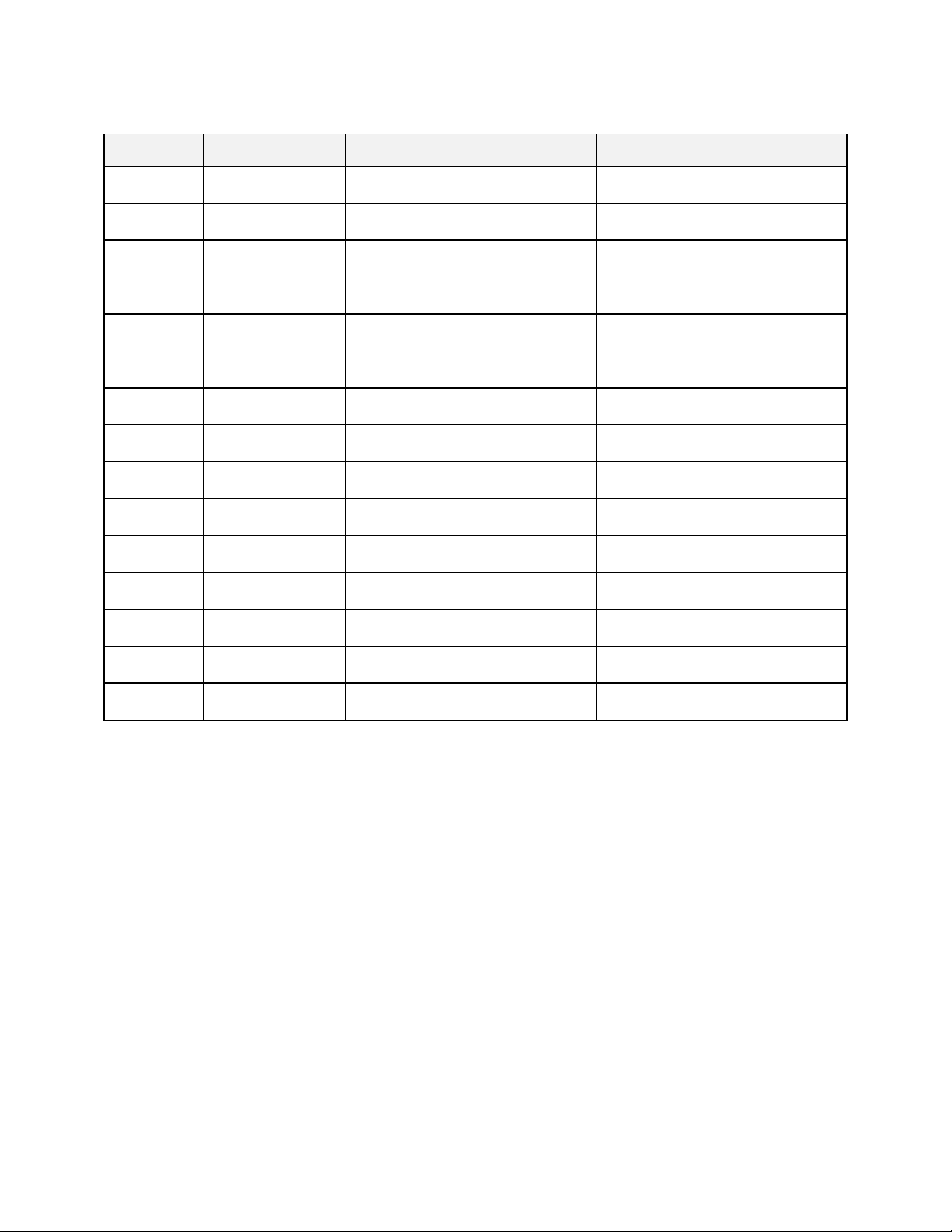
44
Menu Item
Display
Description
Range
Enable
Autostart
Auto Start Enable
Enable (yes) or disable (no) the
Autostart function
No, Yes
Sunday
mode
Auto Start Sun
Mode
Set mode on Sunday to activate
Off, Manual, Timer, Pro-1 to Pro-8
Sunday
time
Auto Start Sun
Time
Set time on Sunday for mode to
activate
00:00 to 23:59
Monday
mode
Auto Start Mon
Mode
Set mode on Monday to activate
Off, Manual, Timer, Pro-1 to Pro-8
Monday
time
Auto Start Mon
Time
Set time on Monday for mode to
activate
00:00 to 23:59
Tuesday
mode
Auto Start Tue
Mode
Set mode on Tuesday to activate
Off, Manual, Timer, Pro-1 to Pro-8
Tuesday
time
Auto Start Tue
Time
Set time on Tuesday for mode to
activate
00:00 to 23:59
Wednesday
mode
Auto Start Wed
Mode
Set mode on Wednesday to
activate
Off, Manual, Timer, Pro-1 to Pro-8
Wednesday
time
Auto Start Wed
Time
Set time on Wednesday for mode
to activate
00:00 to 23:59
Thursday
mode
Auto Start Thu
Mode
Set mode on Thursday to activate
Off, Manual, Timer, Pro-1 to Pro-8
Thursday
time
Auto Start Thu
Time
Set time on Thursday for mode to
activate
00:00 to 23:59
Friday
mode
Auto Start Fri
Mode
Set mode on Friday to activate
Off, Manual, Timer, Pro-1 to Pro-8
Friday time
Auto Start Fri
Time
Set time on Friday for mode to
activate
00:00 to 23:59
Saturday
mode
Auto Start Sat
Mode
Set mode on Saturday to activate
Off, Manual, Timer, Pro-1 to Pro-8
Saturday
time
Auto Start Sat
Time
Set time on Saturday for mode to
activate
00:00 to 23:59
Page 55

45
Menu Item
Display
Description
Range
Display units
PID Temp Unit
Set display units to °C or °F
°C or °F
Proportional
band
PID Prop Band
Set proportional band for tuning
1 to 56°C (1 to 100°F)
Integral reset
PID
Reset/Rep/Min
Set integral reset for tuning
0.0 to 100 seconds/repeat
Derivative
Rate
PID Rate In Sec
Set derivative rate for tuning
0.0 to 500 seconds
AutoTune
PID AutoTune
Enable auto tuning function
Disable, Enable
PID Page
The PID Page contains parameters which control the response to the setpoint and
process variable input. To access the PID Page, enter the Setup Mode. Press the Page
key until PID is displayed. Press the Menu key. Each parameter can be changed by
pressing the Menu key until the desired parameter is displayed, and then pressing the
keys to change the value.
The AutoTune parameter disables or enables the AutoTune function. To utilize
AutoTuning:
1. Access the Setup Mode.
2. Press the Page key until the display reads AutoTune. Press the key to enable
the AutoTune.
3. Press the Page key for three seconds to exit Setup Mode.
4. Cycle power to the instrument.
5. Set Manual Mode to run. The display will alternately display AutoTune and
Manual.
If the Manual Mode setpoint is less than 50 degrees higher than the actual process
temperature, the AutoTune function will create an error condition. This can be cleared
by either cooling off the process temperature or increasing the setpoint until there is
more than 50 degrees between them. Once the AutoTune function is allowed to
complete tuning, the AutoTune parameter will disable by itself.
If you wish to cancel the AutoTune function, press the STOP key, access the PID page
in Setup Mode, and set the AutoTune parameter to Disable.
Page 56

46
Menu Item
Display
Description
Range
Cycle Time
Control Cycle
Time Sec
Set cycle time in seconds for
control output
1 to 60 seconds
High limit
setpoint
Control Hi-Lim
SP***
Maximum value for all high limit
setpoints
MinHiLimSP - MaxHiLimSP*
High limit
band
Control Hi-Lim
Band
If=0, high limit setpoint= Control
Hi-Lim SP If>0, high limit
setpoint= Control SP* + Band
Off, 3°C to 11°C (5°F to 20°F)
Power fail
recovery
Control PwrFRec
Controls response to loss of
power
Stop, Restart, Hold, Resume
Recovery
time limit
Control PFRTime
Control aborts to Stopped mode if
power is lost for time period
longer then set value
00m00s to 99m59s
Powerup
start enable
ControlPwrUpStrt
Allows mode to automatically
start when power is first applied
Disable, Enable
Powerup
Start Mode
Control StrtMode
Operating mode for powerup start
Off, Manual, Timer, Pro-1 to Pro-8
Hysteresis
Control
Hysteresis
Hysteresis for all alarms and
temperature events
1°C to 56°C (1°F to 100°F)
Process out
low
Control
RetOutLo
Process value for retransmit
output = 1VDC
-73°C to 760°C (-100°F to 1400°F)
Process out
high
Control RetOutHi
Process value for retransmit
output = 5VDC
-73°C to 760°C (-100°F to 1400°F)
Time scale
Control
TimeScale
Time scale setting for program
and timer mode**
hh:mm or mm:ss
Key press
beep
Control KeyBeep
Internal beeper sounds when key
is pressed
On or Off
End of cycle
beep
Control
EOCBeep
Internal beeper sounds at end of
cycle
On or Off
Alarm beep
Control
AlarmBeep
Internal beeper sounds for alarms
On or Off
Control Page
The Control Page contains various parameters which control miscellaneous functions.
To access the Control Page, enter the Setup Mode. Press the Page key until Control is
displayed. Press the Menu key. Each parameter can be changed by pressing the Menu
key until the desired parameter is displayed, and then pressing the keys to change
the value.
* includes ramping setpoints during profiles and controlled ramps
** power fail recovery time limit is always MM:SS regardless of time scale setting
*** high limit setpoint is a read-only item which is calculated on Enable page
Page 57
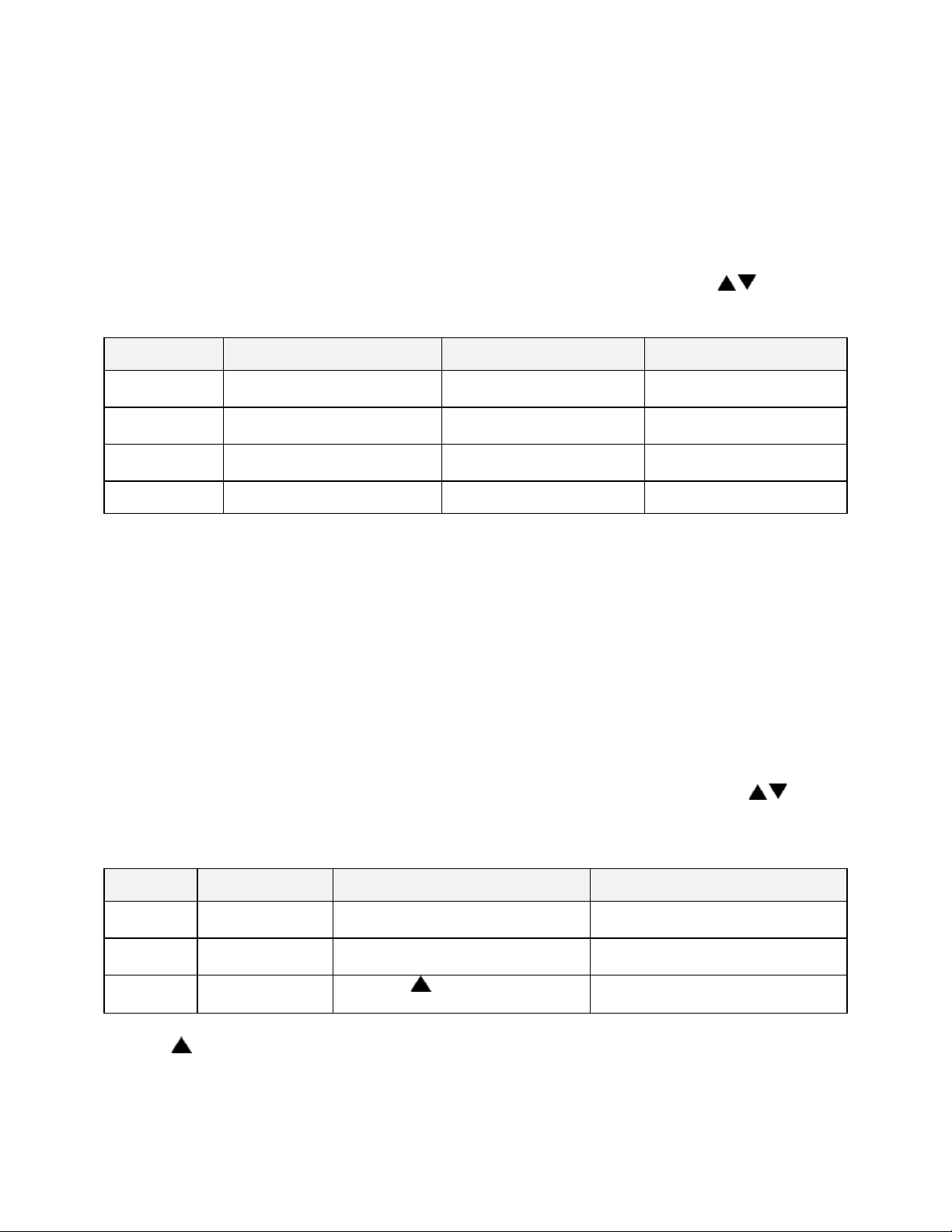
47
Menu Item
Display
Description
Range
Address
Communication CommAddr
Sets address node for
control
1 to 247
Mode
Communication Mode
Turns on/off
communications
OFF, Modbus
Baud Rate
Communication BaudRate
Sets interface speed
2400, 4800, 9600, 19.2K,
38.4K
Parity
Communication Parity
Sets parity for interface
None, Odd, Even
Menu Item
Display
Description
Range
Day of the
week
Clock Day
Setting for current day of the week
Sun, Mon, Tue, Wed, Thu, Fri, Sat
Time of
day
Clock HH:MM
Setting for current time of the day
00:00 to 23:59
Reset
clock
Clock UP to
Reset CLK*
Press the key to set the clock
to entered values
Ready, Done
Communication Page (optional)
The Communication Page contains parameters for the communications feature. To
access the Communications Page, enter the Setup Mode (see description earlier in this
manual). Press the Page key until Communication is displayed. Press the Menu key.
(NOTE: If there is no change in the display, the controller does not have the
communications board installed.) Each parameter can be changed by pressing the
Menu key until the desired parameter is displayed, and then pressing the keys to
change the value.
Real Time Clock Page
The Real Time Clock Page allows the control to be configured to have an operating
mode begin automatically at a specific time on a specific day of the week. The real time
clock feature is also used for using the Power Failure Recovery mode Time Limit
feature (see Control Page). The real time clock is a seven day, 24 hour clock with
battery backup.
To access the Real Time Clock Page, enter the Setup Mode. Press the Page key until
Clock is displayed. Press the Menu key. Each parameter can be changed by pressing
the Menu key until the desired parameter is displayed, and then pressing the keys
to change the value.
* If the key is not pressed, the clock values will retain their original values. The
display will change to Done if the clock is reset
Page 58

48
Menu Item
Display
Description
Range
Type of relay
Relay 1
RelayType
Set function of relay
Off, Alarm, Cycl, Ev1 to Ev4
Action of relay
Relay 1
RelayAction
Set coil and contact state of
relay
NDE, NE, NDEL, NEL*****
Type of
alarm*
Relay 1
AlarmType
Set alarm type for relay
High, Low, Plus, Minus, Band
Alarm
setpoint*
Relay 1 AlmHi/Lo
SP
Setpoint for alarm
-73°C to 760°C (-100°F to 1400°F)
Alarm
deviation*
Relay 1
AlmDevBand
Deviation band for alarm
1 to 56°C (1 to 100°F)
Inhibit alarm*
Relay 1
ALMInhibit
Inhibits alarm until "safe"
condition is reached
En or Dis
Type of
event**
Relay 1
EventType
Set event type for relay
Time or Temp
Event
setpoint***
Relay 1 Event SP
Setpoint for temperature event
SPLoLim to SPUpLim****
Relay Outputs Page (optional)
The Relay Outputs Page configures the four alarm/event outputs. Each output has a
dedicated indicator light and can be configured as a temperature alarm, profile event, or
end of cycle output. Temperature alarms can be of type process high, process low,
deviation high, deviation low, or deviation band.
To access the Relay Page, enter the Setup Mode (see description earlier in this
manual). Press the Page key until Relay is displayed. Press the Select key until the
desired relay output is selected. Press the Menu key. Each parameter can be changed
by pressing the Menu key until the desired parameter is displayed, and then pressing
the keys to change the value. To configure a specific relay, press the Select key
until the desired relay appears.
NOTE: If Relay 0 appears, then no relays are installed (see relay kit assembly p.n.
144562).
(repeat for relay outputs 2-4, if available)
* appears only for alarm types
** appears only for time or temperature event types
*** appears only for temperature event types
Turning on the Alarm Inhibit function disables the alarm output on power up until the
process temperature has reached a non-alarming condition ("safe").
If the relay output has been configured as latching, the RESET key must be pressed to
return the output to the non-alarm state once the alarm condition has cleared.
Page 59

49
Menu Item
Display
Description
Range
Heater
output
Test HeatOut
Activate SSR output 100%
On
High limit
relay
Test HiLimOut
Activate high limit alarm
(de-energize relay)
On
Relay 1
output
Test Rly1 Out
Energize relay output 1
On
Relay 2
output
Test Rly2 Out
Energize relay output 2
On
Relay 3
output
Test Rly3 Out
Energize relay output 3
On
Relay 4
output
Test Rly4 Out
Energize relay output 4
On
HiLim
Sensor
Test HL Temp
(push and hold up)
Displays sensor reading*
Test Page
The Test Page contains parameters which allow manual control of the heat control and
optional relay outputs and should be used only for testing the functionality of the control
instrument. Do not operate the oven for processes using the Test Page.
To access the Test Page, enter the Setup Mode (see description earlier in this manual).
Press the Page key until Test is displayed. Press the Menu key. Each parameter can be
changed by pressing the Menu key until the desired parameter is displayed, and then
pressing the keys to change the value.
*Push key to refresh display
When the Test Page is entered, all outputs are automatically set to off. When exiting
the Test Page, all outputs will return to their previous condition regardless of the Test
Page settings.
Page 60

50
Menu Item
Display
Description
Range
Zone 1
actual
Zone Cal
Zone1Act
Point at which Zone 1 is set (center
of chamber)
-73°C to 760°C (-100°F to 1400°F)
Zone1
displayed
Zone Cal
Zone1Dis
Desired displayed value for Zone 1
setting
-73°C to 760°C (-100°F to 1400°F)
Zone 2
actual
Zone Cal
Zone2Act
Point at which Zone 2 is set (center
of chamber)
-73°C to 760°C (-100°F to 1400°F)
Zone2
displayed
Zone Cal
Zone2Dis
Desired displayed value for Zone 2
setting
-73°C to 760°C (-100°F to 1400°F)
Factory
calibration*
Zone Cal
FactCal
Restores the factory calibration
values
Ready or Done (push- key)
Zone Calibration Page
The Zone Calibration Page allows adjustment of the displayed temperature versus the
actual temperature measured by the control thermocouple. This may be desirable in
certain conditions where the center of the oven chamber is not the same temperature as
the control thermocouple. This may occur when the oven is not allowed to soak at a
constant temperature for long periods of time, or the oven is being used at high
temperature.
There is also a Factory Calibration Recovery which will restore the factory calibration
values when the control was first shipped by the manufacturer. This may be helpful if
the calibration has been lost and a calibration instrument is not readily available. To use
the Factory Calibration Recovery feature only, bypass the Zone 1 and Zone 2
calibration parameters by pressing the Menu key.
To access the Zone Calibration Page, enter the Setup Mode (see description earlier in
this manual). Press the Page key until Zone Cal is displayed. Press the Menu key. Each
parameter can be changed by pressing the Menu key until the desired parameter is
displayed, and then pressing the keys to change the value.
*Only use when no calibration instrument is available, push key to restore factory
values.
Press the Page key to exit the Zone Calibration Page.
Two points of display calibration (temperature offset) are available. The Zone 1 Actual
and Zone 2 Actual parameters are the two temperature points where the offset is to take
effect. These values are adjustable. The Zone 1 and Zone 2 Displayed parameters are
the values the user wishes to have displayed at the Actual temperatures, and are also
adjustable.
Page 61

51
As an example, the control is displaying 400°F with the setpoint being 400°F, but the
center of the oven chamber is actually 395°F. This can occur due to oven wall losses
and product loading variations. The operator may change the zone calibration so that
the center of the oven is 400°F when the display reads 400°F. In this case operate the
oven in manual mode with a setpoint of 400°F. Record the center of the chamber (as
measured with an independent sensor). Access the Zone Calibration Page and enter
this measured value as the Zone 2 Actual value, with 400° as the Zone 2 Displayed
value.
Zone 1 can be adjusted using the same method at a lower temperature. The instrument
will then create a linear offset based on the Zone1 and Zone 2 Actual temperature
values. Note that the oven does not have to be heated to adjust the zone parameters if
the zone values are known based on prior experience.
Page 62

52
Sensor Calibration Page
The Sensor Calibration Page has parameters which can change the internal calibration
of the temperature sensor input signal. There is a low and high calibration point for both
the control sensor and the high limit sensor. To calibrate the instrument, allow the
control to warm up for at least 30 minutes.
To access the Sensor Calibration Page, enter the Setup Mode (see description earlier in
this manual). Press the Page key until Control Sensor is displayed. Press the Menu
key.
The control may have the optional process value retransmission output feature. The
output is a 1 to 5VDC signal. To calibrate the retransmit signal, the RetOutLo and
RetOutHi values from the Control Page must be known. You may bypass calibrating
the control and high limit sensor input to access only the retransmit calibration by
pressing the Menu key until RetCalLo is displayed (skip steps 4-17).
To re-calibrate the instrument:
Page 63

53
1. Disconnect the control and high limit sensor thermocouples.
2. Connect a calibration instrument with a type J thermocouple output to the
control sensor input. Allow the control to warm up at least 30 minutes.
3. Access Setup Mode.
4. Press Page key until -100F is displayed.
5. Press Menu key until Ctrl Sens -100F is displayed.
6. With Ctrl Sens -100F displayed, adjust the calibration instrument to Type J
thermocouple, -100 degrees Fahrenheit output.
7. Wait 30 seconds. Press the key.
8. With Ctrl Sens 1400F displayed, adjust the calibration instrument to 1400
degrees Fahrenheit output (Type J thermocouple).
9. Wait 30 seconds. Press the key.
10. When the control displays Ctrl Sens Done, disconnect the calibration
instrument from the control sensor input and connect it to the high limit sensor
input. Reconnect the control sensor thermocouple.
11. Press the Menu key until HL Sens -100F is displayed.
12. With the control displaying HL Sens -100F, adjust the calibration instrument
to -100 degrees Fahrenheit output (Type J thermocouple).
13. Wait 30 seconds. Press the key.
14. With the control displaying HL Sens 1400F, adjust the calibration instrument
to 1400 degrees Fahrenheit output (Type J thermocouple).
15. Wait 30 seconds. Press the key.
16. When the control displays HL Sens Done, disconnect the calibration
instrument from the high limit sensor input. Re-connect the high limit sensor
thermocouple.
17. To skip calibration of the retransmit signal, press the Page key twice to exit the
Sensor Calibration Page.
18. To calibrate the retransmit signal, press the Menu key until RetCalLo is
displayed.
19. Connect a calibration instrument with a type J thermocouple output to the
control sensor input.
20. Connect a voltage measurement device to the retransmit output terminals.
21. Set the calibration instrument output to the temperature value of the RetOutLo
parameter from the Control Page.
22. Adjust the RetCalLo * value using the keys until the voltage measurement
device reads 1VDC.
23. Press the Menu key.
24. Set the calibration instrument output to the temperature value of the RetOutHi
parameter from the Control Page.
25. Adjust the RetCalHi * value using the keys until the voltage measurement
device reads 5VDC.
26. Press the Menu key.
27. Press the Page key to exit the Sensor Calibration Page.
28. Calibration is now complete. Disconnect the calibration instrument and voltage
measurement device (if used).
29. Verify that the control and high limit sensor thermocouples are connected.
Page 64

54
Menu Item
Display
Description
Range
Control Sensor
Cal
Ctrl Sens -100F
Ctrl Sens 1400F
Ctrl Sens Done
Calibrate Sensor Low End
Calibrate Sensor High End
Control Sensor Cal Complete
-100 to 1400°F
-100 to 1400°F
(read only)
HiLim Sensor
Cal
HL Sens -100F
HL Sens 1400F
HL Sens Done
Calibrate HiLim Sensor Low
End
Calibrate HiLim Sensor High
End
HiLim Sensor Cal Complete
-100 to 1400°F
-100 to 1400°F
(read only)
Retransmit Cal
RetCalLo XXXX *
RetCalHi XXXX *
Calibrate Retransmit Output
Low
Calibrate Retransmit Output
High
0 to 4096**
0 to 4096***
*Note that the actual RetCalLo and RetCalHi values displayed are of no importance.
Page 65
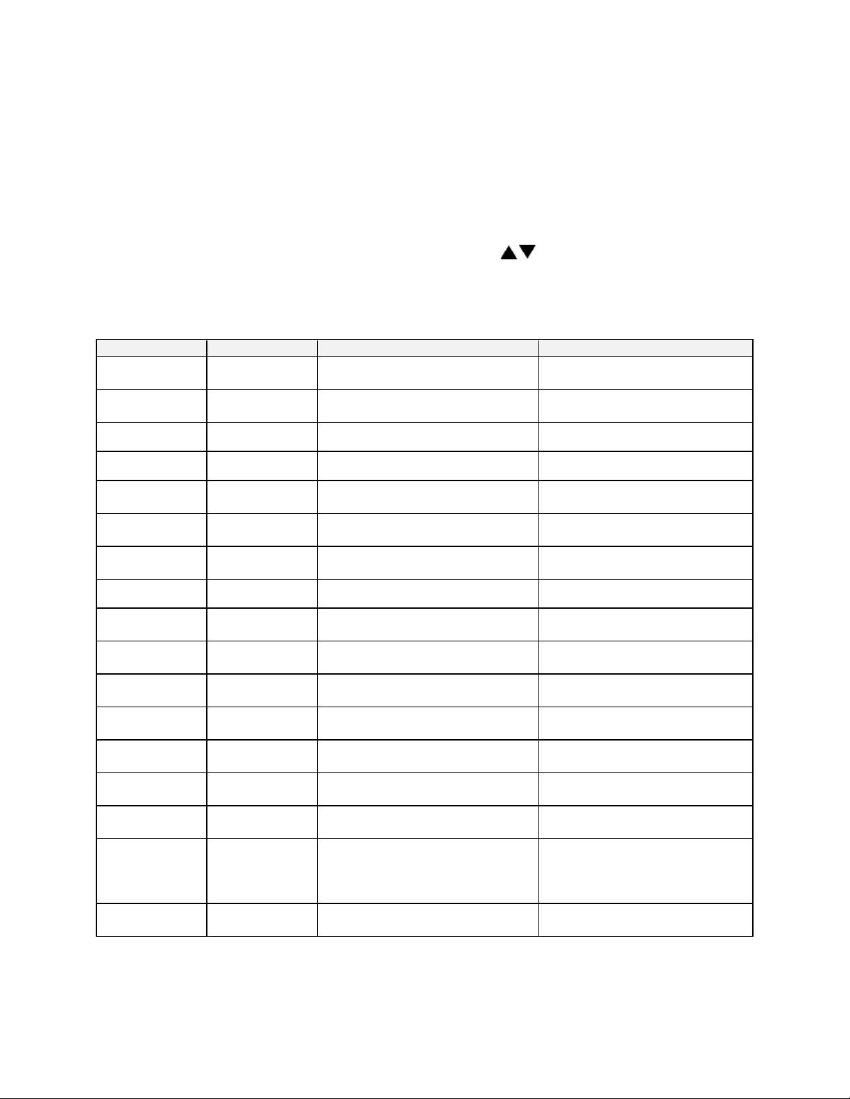
55
Menu Item
Display
Description
Range
Profiles
Enable Profile
1-8
Controls access to Program Page
Yes or No
Autostart
Enable Auto
Start
Controls access to AutoStart
Page
Yes or No **
PID
Enable PID
Controls access to PID Page
Yes or No
Control
Enable Control
Controls access to Control Page
Yes or No
Communication
Enable
Communication
Controls access to
Communication Page
Yes or No **
Real Time
Clock
Enable Clock
Controls access to Real Time
Clock Page
Yes or No **
Relay outputs
Enable Relay
1-4
Controls access to Relay Page
Yes or No **
Test
Enable Test
Controls access to Test Page
Yes or No
Zone
Calibration
Enable Zone
Cal
Controls access to Zone
Calibration Page
Yes or No
Sensor
Calibration
Enable Sensor
Cal
Controls access to Sensor
Calibration Page
Yes or No
Setpoint lower
limit
Enable
SPLowerLim
Sets minimum setpoint allowed
-73°C to 759°C (-100°F to 1399°F)
Setpoint upper
limit
Enable
SPUpperLim
Sets maximum setpoint allowed
-73°C to 760°C (-100°F to 1400°F)
High limit
overhead
Enable
HiLimOH
Sets maximum high limit setpoint
allowed*
3 to 11°C (5 to 20°F)*
Password level
1
Enable
Password 1
Sets password for access level 1
0 to 999
Password level
2
Enable
Password 2
Sets password for access level 2
0 to 999
Setpoint
Change
Enable
SPChange
Set to DISABLE to lock out
setpoint and high limit setpoint
changes in Manual and Timer
Modes
Yes or No
Analog Output
Type
Enable Analog
Type
Sets Analog Output type
Ctrl or Proc
Enable Page
The Enable Page controls access to the other Setup Pages. The setpoint minimum and
maximum values, and the security passwords are also set on the Enable Page.
To access the Enable Page, enter the Setup Mode using a level 2 access code (see
description earlier in this manual). Press the Page key until Enable is displayed. Press
the Menu key. Each parameter can be changed by pressing the Menu key until the
desired parameter is displayed, and then pressing the keys to change the value.
NOTE: Changing the enable to “yes” for each page will allow access to the page in
Level 1 security.
* Maximum high limit setpoint = SPUpperLim + HiLimOH
** If the controller does not have this feature, “No” is the only option.
Page 66

56
Input 1
Input 2
Input 3
Profile Selected
ON
OFF
OFF
1
OFF
ON
OFF
2
ON
ON
OFF
3
OFF
OFF
ON
4
ON
OFF
ON
5
OFF
ON
ON
6
ON
ON
ON
7
OFF
OFF
OFF
none
Digital Inputs (optional)
The Protocol Plus control can be run by external inputs wired to the control from an
external source such as a PLC or control panel switches. The external run operation
can Run, Hold or Stop profiles 1 through 7 (profile 8 can not be operated externally).
Refer to the table below for the inputs required for the desired operation. NOTE: A
profile must be created in the program page before trying to run a profile number.
To start the selected profile, set Input 1, 2, 3 or 4 to ON.
To hold a profile, set Input 4 to OFF.
To stop a profile, set all inputs to OFF.
Digital Inputs
Page 67

57
Error Messages and Alarms
The Alarm Status Hi-limit LED is flashing. This indicates a problem with the
thermocouple, or the Hi-limit setpoint has been exceeded. Once the problem has
corrected, press the Reset pushbutton.
The Alarm Status Soak LED is flashing. This indicates that the oven temperature has
not entered or dropped out of the soak band and the soak timer has stopped.
The top LED Display reads OPEN and the lower LCD display reads CONTROL SENS
ERR. This indicates that the Control thermocouple is disconnected or broken. Repair
or replace the thermocouple.
The lower LCD display reads HI-LIM SENS ERR. This indicates that the Hi-limit
thermocouple is disconnected or broken. Repair or replace the thermocouple.
The lower LCD display reads HIGH LIMIT ALARM. This indicates that the Hi-limit
temperature setpoint has been exceeded. Determine if the setting is set too close to the
setpoint, the SSR is defective, or the calibration is incorrect.
Note: The lower LCD display intermittently reads HL Temp. This is not an error
message, but the Hi-limit thermocouple temperature reading.
Page 68

58
Menu Item
Display
Default
Range
Setting
Ramp Time Seg 1
Pro-1 Seg-1 Ramp Time
00:00
00m00s to
99h59s
Event 1 Set Value
Pro-1 Seg-1 Ramp Event 1
Off
Off, On
Event 2 Set Value
Pro-1 Seg-1 Ramp Event 2
Off
Off, On
Event 3 Set Value
Pro-1 Seg-1 Ramp Event 3
Off
Off, On
Event 4 Set Value
Pro-1 Seg-1 Ramp Event 4
Off
Off, On
Soak Temp Seg 1
Pro-1 Seg 1 Soak Temp
68°F
SPLowerLim to
SPUpperLim *
Soak Time Seg 1
Pro-1 Seg 1 Soak Time
00:00
00m00s to
99h59s
Event 1 Set Value
Pro-1 Seg-1 Soak Event 1
Off
Off, On
Event 2 Set Value
Pro-1 Seg-1 Soak Event 2
Off
Off, On
Event 3 Set Value
Pro-1 Seg-1 Soak Event 3
Off
Off, On
Event 4 Set Value
Pro-1 Seg-1 Soak Event 4
Off
Off, On
(repeat for segments 2-8)
High Limit Setpoint
Pro-1 Hi-Lim SP
Max
HiLimSP
MinHiLimSP to
MaxHiLimSP *,
Band **
Loop From
Pro-1 Loop From XX
No
No, Seg-1 to
Seg-8
Loop To
Pro-1 Loop To XX
No
No, Seg-1 to
Seg-8
Loop Count
Pro-1 Loop Number
0
0 to 99
Profile Link
Pro-1 Link To XX
Stop
Standby***,
Stop, Hold,
Pro-1 to Pro-8
Guaranteed Soak
Pro-1 Guar Band
Off
Off, 1 to 778°C
(1400°F)
(repeat for profiles 2-8)
Quick Reference and Default Values
Program Page
* See Enable Page
** Band value is set on Control Page
*** If Standby
1. Cycle Complete LED indication goes ON.
2. Controller beeps if End Of Cycle beep is enabled.
3. Heater/control output keeps controlling oven temperature at last Soak setpoint.
4. All events programmed (if relay cards installed and programmed as an event) for
the last Soak Segment stays active.
Page 69

59
Programming Table
Seg-
ment
Ramp
Soak
Time
Events
Temp-
erature
Time
Events
1 2 3 4 1 2 3
4
1
2 3 4
5
6
7
8
High Limit Setpoint
Loop From Seg
Loop To Seg
Loop Number
Link To Pro
Guar Soak Band
Profile Number__________
Profile Name__________
Page 70

60
Autostart
Menu Item
Display
Default
Range
Setting
Enable Autostart
Auto Start Enable
No
No, Yes
Sunday mode
Auto Start Sun Mode
Off
Off, Manual, Timer, Pro-1 to Pro-8
Sunday time
Auto Start Sun Time
00:00
00:00 to 23:59
Monday mode
Auto Start Mon Mode
Off
Off, Manual, Timer, Pro-1 to Pro-8
Monday time
Auto Start Mon Time
00:00
00:00 to 23:59
Tuesday mode
Auto Start Tue Mode
Off
Off, Manual, Timer, Pro-1 to Pro-8
Tuesday time
Auto Start Tue Time
00:00
00:00 to 23:59
Wednesday mode
Auto Start Wed Mode
Off
Off, Manual, Timer, Pro-1 to Pro-8
Wednesday time
Auto Start Wed Time
00:00
00:00 to 23:59
Thursday mode
Auto Start Thu Mode
Off
Off, Manual, Timer, Pro-1 to Pro-8
Thursday time
Auto Start Thu Time
00:00
00:00 to 23:59
Friday mode
Auto Start Fri Mode
Off
Off, Manual, Timer, Pro-1 to Pro-8
Friday time
Auto Start Fri Time
00:00
00:00 to 23:59
Saturday mode
Auto Start Sat Mode
Off
Off, Manual, Timer, Pro-1 to Pro-8
Saturday time
Auto Start Sat Time
00:00
00:00 to 23:59
Menu Item
Display
Default
Range
Setting
Display units
PID Temp Unit
°C
°C or °F
Proportional band
PID Prop Band
6°C
1 to 56°C (1 to 100°F)
Integral reset
PID Reset
2
0 to 100 seconds/repeat
Derivative Rate
PID Rate
0
0 to 500 seconds
AutoTune
PID AutoTune
Disable
Disable, Enable
PID
Page 71

61
Control
Menu Item
Display
Default
Range
Setting
Cycle Time
Control Cycle Time
1
1 to 60 seconds
High limit setpoint
Control Hi-Lim SP
Max HiLimSP
MinHiLimSP - MaxHiLimSP*
High limit band
Control Hi-Lim Band
Off
Off, 3°C to 11°C (5°F to 20°F)
Power fail recovery
Control PwrFRec
Stop
Stop, Restart, Hold, Resume
Recovery time limit
Control PwrFTime
00m00s
00m00s to 99m59s
Powerup start enable
Control EPwrStrt
Dis
Dis, En
Powerup Start Mode
Control StrtMode
Off
Off, Manual, Timer, Pro-1 to Pro-8
Hysteresis
Control Hyst
3°C
1°C to 56°C (1°F to 100°F)
Process out low
Control RetOutLo
80°C
-73°C to 760°C (-100°F to 1400°F)
Process out high
Control RetOutHi
400°C
-73°C to 760°C (-100°F to 1400°F)
Time scale
Control TimeScale
hh:mm
hh:mm or mm:ss
Key press beep
Control KeyBeep
On
On or Off
End of cycle beep
Control EOCBeep
Off
On or Off
Alarm beep
Control AlarmBeep
Off
On or Off
Menu Item
Display
Default
Range
Setting
Address
Communication CommAddr
1
1 to 247
Mode
Communication CommMode
OFF
OFF, Modbus
Baud rate
Communication Baud Rate
19.2K
2400, 4800, 9600,
19.2K, 38.4K
Parity
Communication Parity
None
None, Odd, Even
*see Enable Page
Communication (optional)
Page 72

62
Menu Item
Display
Default
Range
Setting
Day of the week
Clock Day
Mon
Sun, Mon, Tue,
Wed, Thu, Fri, Sat
Time of day
Clock HH:MM
00:00
00:00 to 23:59
Reset clock
Clock UP to Reset CLK*
Ready
Ready, Done
Menu Item
Display
Default
Range
Type of relay
Relay 1 RelayType
Off
Off, Alarm, Cycl, Ev1 to Ev4
Action of relay
Relay 1 RelayAction
NDE
NDE, NE, NDEL, NEL*****
Type of alarm*
Relay 1 AlarmType
High
High, Low, Plus, Minus, Band
Alarm setpoint*
Relay 1 AlmHi/Lo SP
538°C
-73°C to 760°C (-100°F to 1400°F)
Alarm deviation*
Relay 1 AlmDevBand
3°C
1 to 56°C (1 to 100°F)
Inhibit alarm*
Relay 1 ALMInhibit
On
En or Dis
Type of event**
Relay 1 EventType
Time
Time or Temp
Event setpoint ***
Relay 1 Event SP
SPUpLim
SPLoLim to SPUpLim****
Relay
Type
Action
Alarm/
Event Type
Setpoint
Alarm
Deviation
Alarm
Inhibit
Real Time Clock
* if the key is not pressed, the clock values will retain their original values, the display
will change to Done if the clock is reset
Relay Outputs (optional)
Push Select key to select relay. If Relay 0 appears, no relays are installed
(repeat for relay outputs 2-4, if available)
* appears only for alarm types
** appears only for time or temperature event types
*** appears only for temperature event types
**** see enable page
***** Normally de-energized and non-latching, normally energized and non-latching,
normally de-energized and latching, normally energized and latching
Table of Settings
Page 73
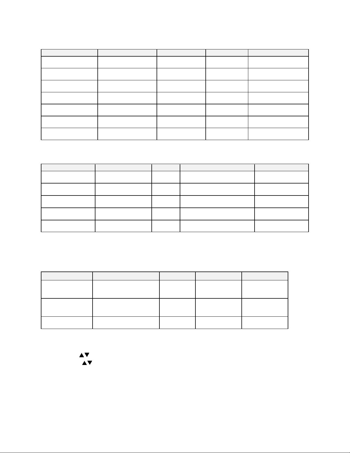
63
Test
Menu Item
Display
Default
Range
Setting
Heater output
Test HeatOut
Off
On
High limit relay
Test HiLimOut
Off
On Relay 1 output
Test Rly1 Out
Off
On
Relay 2 output
Test Rly2 Out
Off
On
Relay 3 output
Test Rly3 Out
Off
On Relay 4 output
Test Rly4 Out
Off
On
High Limit Sensor
Test HL Temp
(sensor reading)
Menu Item
Display
Default
Range
Setting
Zone 1 actual
Zone Cal Zone1Act
38°C
-73°C to 760°C (-100°F to
1400°F)
Zone1 displayed
Zone Cal Zone1Dis
38°C
-73°C to 760°C (-100°F to
1400°F)
Zone 2 actual
Zone Cal Zone2Act
260°C
-73°C to 760°C (-100°F to
1400°F)
Zone2 displayed
Zone Cal Zone2Dis
260°C
-73°C to 760°C (-100°F to
1400°F)
Factory calibration*
Zone Cal FactCal
Ready
Ready or Done (push- key)
Menu Item
Display
Default
Range
Setting
Control Sensor Cal
Ctrl Sens 0F
Ctrl Sens 1000F
Ctrl Sens Done
-100°F
1400°F
Done
-100 to 1400°F
-100 to 1400°F
(read only)
HiLim Sensor Cal
HL Sens 0F
HL Sens 1000F
HL Sens Done
-100°F
1400°F
Done
-100 to 1400°F
-100 to 1400°F
(read only)
Retransmit Cal
RetCalLo XXXX *
RetCalHi XXXX *
0
4096
0 to 4096**
0 to 4096***
Zone Cal
*only use when no calibration instrument is available
Sensor Cal
* note that the actual RetCalLo and RetCalHi values displayed are of no
importance.
** press keys until retransmission output = 1VDC
*** press keys until retransmission output = 5VDC
Page 74

64
Enable Page
Menu Item
Display
Default
Range
Setting
Profiles
Enable Profile 1-8
Yes
Yes or No
Autostart
Enable Auto Start
No
Yes or No **
PID
Enable PID
Yes
Yes or No
Control
Enable Control
No
Yes or No
Communication
Enable Communication
No
Yes or No **
Real Time Clock
Enable Clock
No
Yes or No **
Relay outputs
Enable Relay 1-4
No
Yes or No **
Test
Enable Test
No
Yes or No
Zone Calibration
Enable Zone Cal
No
Yes or No
Sensor Calibration
Enable Sensor Cal
No
Yes or No
Setpoint lower limit
Enable SPLowerLim
20°C
-73°C to 759°C (-100°F to
1399°F)
Setpoint upper limit
Enable SPUpperLim
260°C
-73°C to 760°C (-100°F to
1400°F)
High limit overhead
Enable HiLimOH
5°C
3 to 11°C (5 to 20°F)*
Password level 1
Enable Password 1
1
0 to 999
Password level 2
Enable Password 2
2
0 to 999
Manual/Timer mode
setpoint change
Enable SPChange
Yes
Yes or No
Analog Output Type
Enable Analog Type
Proc
Ctrl or Proc
* Maximum high limit setpoint (MaxHiLimSP) = SPUpperLim + HiLimOH
Minimum high limit setpoint (MinHiLimSP) = SPLowerLim + HiLimOH
** If the controller does not have this feature, “No” is the only option.
Page 75

65
Technical Specifications
UL, cUL listed:
UL file E136675
CE compliance to:
EMC Directive 89-366/EEC
European Standard EN55011/1991
European Standard EN50082-2/1995
Power supply:
100 to 240 VAC +10% -15%, 50-60Hz, 30VA Maximum
12 to 24 VAC/VDC +/-10%, DC to 60Hz, 30VA Maximum
Temperature:
Storage -20 to 60°C
Operating 0 to 50°C
Humidity:
90% or less, non-condensing
Sensor inputs:
Type J thermocouple -73°C to 760°C (-100°F to 1400°F)
Input impedance 1M ohm or greater
Common mode noise rejection of 140db@60Hz
Common mode input voltage of +/-12.0VDC
Sample rate of at least 1 sample per second
Stability of +/- 0.5°C per 5°C change in ambient temperature
Repeatability of +/- 0.5°C, or +/-0.1% of sensed temperature (whichever is
greater)
Accuracy (@ 77°F +/-0.2 percent of span (+/-3°F)
Supply Voltage Influence of +/-0.5°C per 10% change in nominal line voltage
Temperature
display:
1 degree resolution (C or F)
Accuracy after calibration of +/- 1°C, or +/-0.2% of sensed temperature
(whichever is greater) @25°C
Four-digit seven-segment LCD, 0.43 inches high (11mm)
Readout Stability (+/-1°F/10°F Change in ambient temperature)
Message display:
Two-line, 16 alpha-numeric 5x7 dot matrix characters per line
0.2 inches high (5mm)
Time base:
+/- 4 seconds accuracy in 24 hours
Heat control
output:
SSR Drive 24VDC nominal @ 70mA
Relay output: (plug-in
module)
Form A dry contact, rated 3 amps @ 24-264VAC
Retransmit output:
1 to 5 VDC into > 100K ohm load
Communications:
(plug-in module)
RS232 Single drop, isolated
RS422 Multi-drop, isolated
RS485 Multi-drop, isolated
Remote inputs:
(plug-in module)
Dry-contact closure type with less than 250 ohm ON resistance
Front panel:
NEMA 4X (with gasket)
Dimensions:
3.57H x 7.24W x 2.84D inches (91H x 184W x 72D mm)
Panel opening:
3.63H x 7.30W inches (92H x 185W mm)
Page 76

66
APPENDIX: DRAWINGS
The following pages contain electrical drawings for the LCC/LCD2-14-3.
Page 77

67
Drawing
157482I01
Page 78

68
Drawing
157482I02
Page 79

69
Drawing
157482I03
Page 80
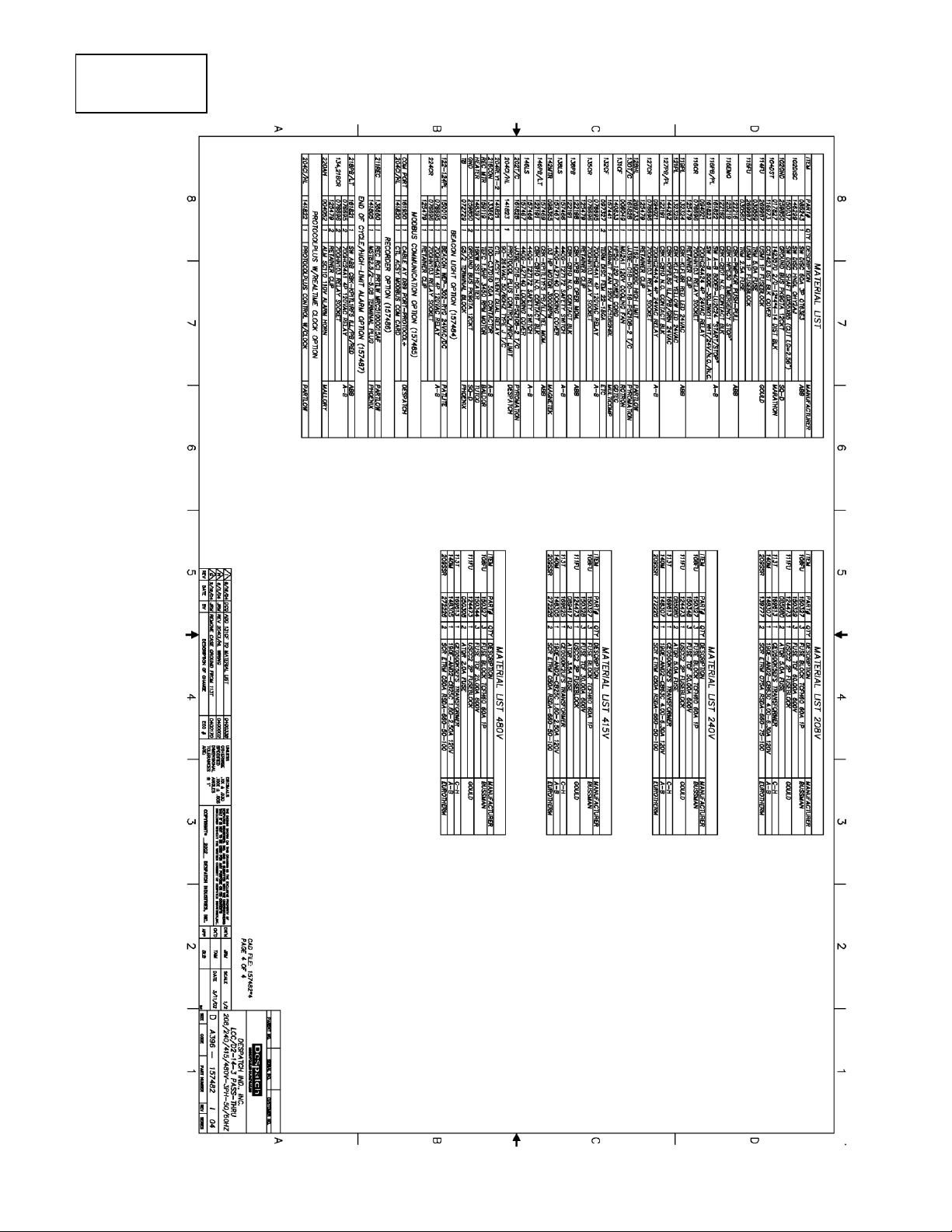
70
Drawing
157482I04
 Loading...