


C-188 P.N. 146230 REVISION L 11/2007
LBB SERIES OVENS
INSTRUCTION MANUAL
LBB Series Despatch Ovens are bench ovens to 204°C (400°F) with forced convection airflow.
MODEL |
VOLTS |
HEATER WATTS |
AMPS |
HZ |
PHASE |
|
|
|
|
|
|
LBB1-23A |
120 |
1,200 |
11.6 |
50/60 |
1 |
|
|
|
|
|
|
LBB1-23B |
240 |
1,200 |
5.8 |
50/60 |
1 |
|
|
|
|
|
|
LBB1-43A |
120 |
1,600 |
15.0 |
50/60 |
1 |
|
|
|
|
|
|
LBB1-43B |
240 |
1,600 |
7.5 |
50/60 |
1 |
|
|
|
|
|
|
LBB1-69A |
120 |
2,400 |
21.6 |
50/60 |
1 |
LBB1-69B |
240 |
2,400 |
10.8 |
50/60 |
1 |
LBB2-12 |
240 |
3,600 |
16.4 |
50/60 |
1 |
|
|
|
|
|
|
LBB2-18 |
240 |
3,600 |
16.4 |
50/60 |
1 |
LBB2-27 |
240 |
4,800 |
21.4 |
50/60 |
1 |
Prepared by: Despatch Industries 8860 207th St. West Lakeville, MN 55044
Customer Service 800-473-7373

NOTICE
Users of this equipment must comply with operating procedures and training of operation personnel as required by the Occupational Safety and Health Act (OSHA) of 1970, Section 6 and relevant safety standards, as well as other safety rules and regulations of state and local governments. Refer to the relevant safety standards in
OSHA and National Fire Protection Association (NFPA), section 86 of 1990.
CAUTION
Setup and maintenance of the equipment should be performed by qualified personnel who are experienced in handling all facets of this type of system. Improper setup and operation of this equipment could cause an explosion that may result in equipment damage, personal injury or possible death.
Dear Customer,
Thank you for choosing Despatch Industries. We appreciate the opportunity to work with you and to meet your heat processing needs. We believe that you have selected the finest equipment available in the heat processing industry.
At Despatch, our service does not end after the purchase and delivery of our equipment. For this reason we have created the Service Products Division within Despatch. The Service Products Division features our
Response Center for customer service. The Response Center will direct and track your service call to ensure satisfaction.
Whenever you need service or replacement parts, contact the Response Center at 1-800-473-7373: FAX 612-781-5353.
Thank you for choosing Despatch.
Sincerely,
Despatch Industries


PREFACE
This manual is your guide to the Despatch oven. It is organized to give you the information you need quickly and easily.
The INTRODUCTION section provides an overview of the Despatch oven.
The THEORY OF OPERATION section details the function and operation of assemblies and subassemblies on the Despatch oven.
The INSTRUCTIONS and CONTROL INSTRUCTIONS sections provide directions on unpacking, installing, operating, maintaining and troubleshooting the Despatch oven.
Read the entire INTRODUCTION and THEORY OF OPERATION before installing the oven.
An efficient way to learn about the oven would be to read the manual while working with the corresponding oven control system. This will give you practical hands-on experience with information in the manual and the oven.
Before operating the equipment, be sure you understand all of the technical information contained in this manual. Information skipped, not understood or misunderstood could create the possibility of operating the equipment in an unsafe manner. This can cause damage to the oven or personnel or reduce the efficiency of the equipment.
WARNING: Failure to heed warnings in this instruction manual and on the oven could result in personal injury, property damage or death.
i
Revision C: |
Updated electrical drawings in DRAWINGS AND SPARE PARTS LISTS |
|
section. |
Revision D: |
Corrections. |
Revision E: |
Correction, page 19, set-up parameter table. |
Revision F: |
Parts lists corrections in DRAWINGS AND SPARE PARTS LISTS section. |
Revision G: |
Corrections to SPECIFICATIONS section, addition of options and features |
|
in APPENDIX |
Revision H: |
Change Product Warranty page. |
Revision I: |
Update drawings and hi-limit information. |
Revision J: |
Parts lists corrections in DRAWING AND SPARE PARTS LISTS section. |
|
Corrected Despatch address. |
Revision K: |
Parts lists corrections in DRAWING AND SPARE PARTS LISTS section. |
Revision L: |
Updated warranty |
ii
Table of Contents |
|
PREFACE ........................................................................................................................ |
i |
INTRODUCTION............................................................................................................. |
1 |
Special Features.......................................................................................................... |
1 |
Specifications .............................................................................................................. |
2 |
Dimensions .............................................................................................................. |
2 |
Power....................................................................................................................... |
3 |
Temperature ............................................................................................................ |
4 |
Capacities ................................................................................................................ |
4 |
THEORY OF OPERATION ............................................................................................. |
5 |
CONTROL Instrument ................................................................................................. |
6 |
HI-LIMIT Instrument..................................................................................................... |
7 |
Product HI-LIMIT Instrument.................................................................................... |
8 |
Oven HI-LIMIT Instrument........................................................................................ |
8 |
Oven Theory ............................................................................................................ |
9 |
INSTRUCTIONS ........................................................................................................... |
10 |
Unpacking and Inspection ......................................................................................... |
10 |
Setup ......................................................................................................................... |
11 |
Operating................................................................................................................... |
12 |
Loading the Oven................................................................................................... |
12 |
Pre-Startup Checklist ............................................................................................. |
13 |
Startup ................................................................................................................... |
14 |
CONTROL INSTRUCTIONS......................................................................................... |
16 |
Changing Setpoint ..................................................................................................... |
16 |
Parameter Programming Mode ................................................................................. |
17 |
Operating Parameters............................................................................................ |
17 |
Operating Parameters............................................................................................ |
18 |
Set-Up Parameters ................................................................................................ |
19 |
Changing Display From °C To °F ..................... |
......................................................... 20 |
Oven Zone Calibration............................................................................................... |
21 |
Calibration Instructions........................................................................................... |
21 |
HI-LIMIT INSTRUCTIONS......................................................................................... |
22 |
Changing Setpoint ..................................................................................................... |
22 |
Parameter Setup Mode.............................................................................................. |
23 |
Setup Parameters...................................................................................................... |
24 |
Changing Display From °C To °F .............................................................................. |
26 |
Maintenance .......................................................................................................... |
27 |
Checklist ................................................................................................................ |
27 |
Tests ...................................................................................................................... |
28 |
Replacement Parts................................................................................................. |
28 |
Replacement of Control Instrument........................................................................ |
29 |
Replacement of Hi-limit Instrument ........................................................................ |
30 |
Replacement of Heater Unit................................................................................... |
31 |
Replacement of Fan Motor..................................................................................... |
32 |
Troubleshooting......................................................................................................... |
34 |
DRAWINGS AND SPARE PARTS LISTS ..................................................................... |
36 |
LBB1-23A-1 Parts .................................................................................................. |
37 |
LBB1-23A-1 Drawing ............................................................................................. |
38 |
|
iii |
LBB1-23B-1 Parts .................................................................................................. |
39 |
LBB1-23B-1 Drawing ............................................................................................. |
40 |
LBB1-43A-1 Parts .................................................................................................. |
41 |
LBB1-43A-1 Drawing ............................................................................................. |
42 |
LBB1-43B-1 Parts .................................................................................................. |
43 |
LBB1-43B-1 DRAWING ......................................................................................... |
44 |
LBB1-69A-1 Parts .................................................................................................. |
45 |
LBB1-69A-1 Drawing ............................................................................................. |
46 |
LBB1-69B-1 Parts .................................................................................................. |
47 |
LBB1-69B-1 Drawing ............................................................................................. |
48 |
LBB2-12-1 Parts..................................................................................................... |
49 |
LBB2-12-1 Drawing................................................................................................ |
50 |
LBB2-18-1 Parts..................................................................................................... |
51 |
LBB2-18-1 Drawing................................................................................................ |
52 |
LBB2-27-1 Parts..................................................................................................... |
53 |
LBB2-27-1 Drawing................................................................................................ |
54 |
DESPATCH CUSTOMER SERVICE............................................................................. |
55 |
Procedures and Customer Responsibilities ............................................................... |
55 |
Attachment A - Sustained Service Support ............................................................ |
56 |
APPENDIX: OPTIONAL FEATURES ............................................................................ |
57 |
Protocol Plus Control Option ..................................................................................... |
57 |
Timer Option .............................................................................................................. |
57 |
Timer Operation ..................................................................................................... |
58 |
Timer Configuration................................................................................................ |
58 |
Stand Assembly Instructions ..................................................................................... |
59 |
Stacking Kit Assembly Instructions ............................................................................ |
60 |
Timer Option with Audible and Visual Alarm.............................................................. |
61 |
High Limit Alarm Option............................................................................................. |
61 |
Recorder Option ........................................................................................................ |
62 |
iv
INTRODUCTION
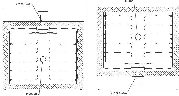
The INTRODUCTION section provides an overview of the Despatch LBB Series Ovens. The LBB Series Ovens have the most effective heat distribution and the fastest processing time of any lab oven its size. Air is discharged through ducts on both sides of the oven distributed through the chamber, and returned through the heater cover.
Special Features
The sturdy construction and high grade insulation of the Despatch LBB Series ovens contribute to excellent high temperature performance. Other special features include:
∙Proportional digital CONTROL instrument to control temperature fluctuations.
∙Manual reset HI-LIMIT instrument to protect the chamber workload as well as the oven itself.
∙Unique Despatch design to combine forced circulated air through side ducts for the ultimate in temperature performance.
∙Welded double wall construction and fiberglass insulation to reduce heat loss. Silicone rubber gaskets further minimize heat leakage.
∙Rapid response heater with a five year warranty.
∙Scratch-resistant baked enamel exterior and stainless steel interior for easy cleaning.
∙Space-saving, stackable design.
∙Optional control panel located on the bottom of the oven.
1
Specifications
Dimensions
|
|
Chamber Size |
|
Capacity |
Overall Size |
|
Shelves |
|
Maximum |
|
|
|||||
|
|
|
in (cm) |
|
|
|
in (cm) |
|
|
|
|
|
||||
|
|
|
|
|
feet3 |
|
|
|
Provided on |
|
Number of Shelf |
|
Chamber |
|||
|
Model |
W |
D |
|
H |
|
(liters) |
W |
D |
H |
|
Shelf Centers |
|
Positions |
|
Doors |
|
|
|
|
|
|
|
|
|
|
|
|
|
|
|
|
|
|
LBB1-23 |
18 |
18 |
|
12 |
2.3 |
24 |
23 |
26 |
|
2 on 2" |
5 |
1 |
|||
|
|
(46) |
(46) |
|
(30) |
(65) |
(61) |
(58) |
(66) |
|
|
|
|
|
|
|
|
LBB1-43 |
24 |
14 |
|
22 |
4.3 |
30 |
19 |
36 |
|
2 on 2" |
10 |
1 |
|||
|
|
(61) |
(36) |
|
(56) |
(122) |
(76) |
(48) |
(91) |
|
|
|
|
|
|
|
|
LBB1-69 |
30 |
18 |
|
22 |
6.9 |
34 |
23 |
36 |
|
2 on 2" |
10 |
2 |
|||
|
|
(76) |
(46) |
|
(56) |
(195) |
(86) |
(58) |
(91) |
|
|
|
|
|
|
|
|
LBB2-12 |
30 |
20 |
|
35 |
12.1 |
36 |
25 |
51 |
|
2 on 2" |
16 |
2 |
|||
|
|
(76) |
(51) |
|
(89) |
(343) |
(91) |
(64) |
(130) |
|
|
|
|
|
|
|
|
LBB2-18 |
37 |
24 |
|
35 |
18 |
43 |
29 |
51 |
|
2 on 2" |
16 |
2 |
|||
|
|
(94) |
(61) |
|
(89) |
(510) |
(102) |
(74) |
(130) |
|
|
|
|
|
|
|
|
LBB2-27 |
37 |
37 |
|
35 |
27.7 |
43 |
42 |
51 |
|
2 on 2" |
16 |
2 |
|||
|
|
(94) |
(94) |
|
(89) |
(785) |
(102) |
(107) |
(130) |
|
|
|
|
|
|
|
|
|
|
|
|
|
|
|
|
|
|
|
|
|
|
|
|
2
Power
Line voltages may vary in some geographical locations. If your line voltage is much lower than the oven voltage rating, warm up time will be longer and motors may overload or run hot. If your line voltage is higher than nameplate rating, the motor may run hot and draw excessive amps.
If the line voltage varies more than 10% from the oven voltage rating, some electrical components such as relays, temperature controls, etc. may operate erratically.
Model |
Volts |
Amps |
Hertz |
Phase |
Heater (KW) |
Cord and Plug |
LBB1-23A |
120 |
11.6 |
50/60 |
1 |
1.2 |
Included, 15 Amp |
LBB1-23B |
240* |
5.8 |
50/60 |
1 |
1.2 |
Included, 15 Amp |
LBB1-43A |
120 |
15.0 |
50/60 |
1 |
1.6 |
Included, 20 Amp |
LBB1-43B |
240* |
7.5 |
50/60 |
1 |
1.6 |
Included, 15 Amp |
LBB1-69A |
120 |
21.6 |
50/60 |
1 |
2.4 |
None, Hardwired |
LBB1-69B |
240* |
10.8 |
50/60 |
1 |
2.4 |
None, Hardwired |
LBB2-12 |
240 |
16.4 |
50/60 |
1 |
3.6 |
None, Hardwired |
LBB2-18 |
240 |
16.4 |
50/60 |
1 |
3.6 |
None, Hardwired |
LBB2-27 |
240 |
21.4 |
50/60 |
1 |
4.8 |
None, Hardwired |
|
|
|
|
|
|
|
∙The LBB1-69, LBB2-12, LBB2-18 and LBB2-27 must be hardwired to the electric supply using 10AWG or larger wires suitable for at least 75°C (167°F).
∙Ovens designed for 240 volts (see name plate on oven) will operate satisfactorily on a minimum of 208 volts, but with a 25% reduction in heater power. If your power characteristics are lower, contact Despatch Industries.
3
Temperature
|
|
|
|
|
LBB |
|
|
||
|
Model |
|
|
|
|
|
|
|
|
|
|
1-23 |
1-43 |
1-69 |
2-12 |
2-18 |
2-27 |
||
|
|
|
|
|
|
|
|
|
|
|
Time to Temperature |
40°C - 150°C |
17 |
17 |
15 |
15 |
17 |
17 |
|
|
(approximate minutes |
|
|
|
|
|
|
|
|
|
with no load) |
40°C - 204°C |
30 |
30 |
26 |
30 |
33 |
33 |
|
|
|
|
|
|
|
|
|
|
|
|
Recovery Time |
150°C |
2 |
2 |
3 |
3 |
3 |
4 |
|
|
Door Open 1 Min. (approx. |
|
|
|
|
|
|
|
|
|
minutes with no load) |
204°C |
4 |
4 |
6 |
6 |
7 |
8 |
|
|
|
|
|
|
|
|
|
|
|
|
Temperature Uniformity |
150°C |
+/- |
+/- |
+/- 3°C |
+/- 2°C |
+/- 3°C |
+/- 3°C |
|
|
At: |
|
3°C |
3°C |
|
|
|
|
|
|
|
204°C |
|
|
+/- 4°C |
+/- 3°C |
+/- 4°C |
+/- 4°C |
|
|
|
|
+/- |
+/- |
|
|
|
|
|
|
|
|
4°C |
4°C |
|
|
|
|
|
|
Operating Range |
|
|
35°C - 204°C |
|
|
40°C - 204°C |
||
|
w/20°C Ambient |
|
|
|
|
|
|
|
|
|
|
|
|
|
|
|
|
|
|
|
Control Stability |
|
|
|
+/- 0.5°C |
|
|
||
|
|
|
|
|
|
|
|
|
|
* Dampers must be open to operate at the minimum temperature.
NOTE: Time to Temperature and Temperature Uniformity values are based on 240V/60 Hz operation, with control panel located on top. Actual results may vary slightly depending on unit configuration and operating conditions.
Capacities
|
|
|
|
|
|
LBB |
|
|
|
|
Model |
|
1-23 |
1-43 |
1-69 |
|
2-12 |
2-18 |
2-27 |
|
Maximum load capacity (lbs) |
200 |
200 |
400 |
|
600 |
600 |
600 |
|
|
|
|
|
|
|
|
|
|
|
|
Maximum shelf load (lbs) |
50 |
50 |
200 * |
|
200 * |
200 * |
200 * |
|
|
|
|
|
|
|
|
|
|
|
|
Exhaust Capacity, CFM |
1 |
2 |
3 |
|
12 |
14 |
14 |
|
|
|
|
|
|
|
|
|
|
|
NOTE: Maximum load capacity not valid with “control panel located on bottom” option.
∙LBB1-69 and larger models have reinforced shelves. Standard duty (50 pounds max) shelves are also available.
WARNING: Do not exceed a total of 400 pounds for stacked LBB1-69.
4
THEORY OF OPERATION
The THEORY OF OPERATION section details the function and operation of assemblies and subassemblies on the Despatch LBB Series Ovens.
The Despatch LBB Series Ovens have the most effective heat distribution system and the fastest processing time of any lab oven its class. These ovens are especially useful for testing, preheating, sterilizing, drying, aging and curing as well as other production applications.
The Despatch LBB Series Ovens incorporate forced circulating airflow with precision digital control to deliver fast processing. The overall result is efficient productivity under strenuous conditions.
The LBB Series Ovens are precise and practical. The unique Despatch design moves convected heat through stainless steel ducts on each side. The air is circulated with a high volume fan. The Despatch LBB Series Ovens employ higher volume fans than any competitive model. The chamber can be densely loaded without interfering with the process. For your convenience the fresh air intake is fixed. The exhaust rate is regulated by a damper on the back of the unit.
Forced Circulating Airflow in Despatch LBB Ovens
5
CONTROL Instrument
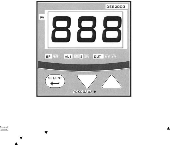
The oven is equipped with a microprocessor based digital control instrument. The Despatch CONTROL instrument has been configured as a proportional controller and set to its optimum operating values. Initially the CONTROL will allow the heater to operate at full power. However, as the actual oven temperature reaches the setpoint, the Proportional Control will cycle the heater on and off, minimizing process temperature fluctuations.
|
CONTROL Instrument |
|
|
Features |
Description |
Main (PV) Display |
Displays the actual oven temperature or displays the setpoint when the set |
|
key is pressed. Displays parameter code and value. |
|
|
Key |
Switches between PV and SP displays. Enters the data changed by the or |
|
keys. Switches through parameter displays. |
Down Key |
Decreases a setpoint or mode parameter. |
|
|
Up Key |
Increases a setpoint or mode parameter. |
LED SP Indicator |
Lights when the setpoint value is displayed. |
LED OUT Indicator |
Lights when the control is calling for heat. |
LED AL1–2 Indicator |
N/A |
|
|
6

HI-LIMIT Instrument
The oven is equipped with a HI-LIMIT instrument. The purpose of the HI-LIMIT instrument is to provide a protective measure for the product and/or the oven itself. If the setting on the HI-LIMIT is exceeded, the heating process will discontinue, thus protecting the product and/or the oven.
Set the HI-LIMIT instrument to a temperature 10°C - 14°C higher than the CONTROL instrument setpoint or a temperature that should not be exceeded in the process. If the setting on the HI-LIMIT instrument is exceeded the heater will shut down. The HI-LIMIT instrument must be manually reset by pushing the RESET button on the HI-LIMIT instrument.
|
HI-LIMIT Instrument |
Features |
Description |
OP1 |
Output 1 status value. (OP2 normally not used for LBB Ovens). |
°C/°F |
Degree indicator. |
PV |
Process value. |
HSP1 |
High limit setpoint 1. (LSP1 normally not used for LBB Ovens). |
SP2 |
Setpoint 2 for output 2 (normally not used for LBB Ovens). |
LOCK |
Lock status indicator. |
|
Scroll Key, used for advancing available displays. |
Up Key |
Increases a setpoint or mode parameter. |
Down Key |
Decreases a setpoint or mode parameter. |
|
Reset the high limit, return to normal display. |
7
Product HI-LIMIT Instrument
If the product being processed has a critical high temperature limit, the HI-LIMIT instrument should be used as a product HI-LIMIT instrument. The HI-LIMIT instrument should be set to a temperature somewhat below the temperature at which the product could be damaged.
Oven HI-LIMIT Instrument
If the product does not have a critical high temperature limit, the HI-LIMIT can be used as an oven HI-LIMIT instrument. An oven HI-LIMIT instrument protects oven equipment. The HI-LIMIT should be set at 204°C
8
Oven Theory
The oven has an efficient forced circulating oven to 204°C (400°F). A forced circulating oven relies on a circulating motor to move air through the chamber , which is much more efficient and uniform than a gravity convected oven. In addition, it takes a finite amount of time for the oven to soak in at the desired setpoint. The time that it takes the unit to soak in at setpoint is related to such parameters as chamber area, load mass and the ability to absorb heat and exhaust rate. The unique Despatch design and CONTROL action compensates for these facts.
The oven uses an indicating microprocessor based digital control that displays the actual chamber temperature at the sensing point. Despatch strategically locates the CONTROL's temperature sensor to optimize the control action for the entire chamber for various load conditions. The CONTROL display may fluctuate a few degrees around the setpoint, but the overall chamber temperature will remain very stable. The underlying reason for this is that the display is showing temperature fluctuations at the temperature sensor location, not the overall chamber temperature. The strategic location of the sensor compensates for delays in heat convection and enhances the performance and temperature control of the oven. The oven has been engineered to have an overall result of quality productivity where fast processing and versatility are critical.
9
INSTRUCTIONS
The INSTRUCTIONS section provides directions on unpacking, installation, operation and maintenance of the Despatch LBB Series Ovens.
Unpacking and Inspection
Remove all packing materials and thoroughly inspect the oven for damage of any kind that could have occurred during shipment.
∙See whether the carton and plastic cover sheet inside carton are still in good condition.
∙Look at all outside surfaces and corners of the oven for scratches and dents.
∙Check the oven controls and indicators for normal movement, bent shafts, cracks, chips or missing parts such as knobs and lenses.
∙Check the door and latch for smooth operation.
If there is damage, and it could have happened during shipment follow these instructions.
1.Contact the shipper immediately and file a written damage claim, before contacting Despatch Industries.
2.Contact Despatch Industries to report your findings and to order replacement parts for those that were damaged or missing.
3.Please send a copy of your filed damage claims to Despatch.
Next, check to make sure you have received all the required materials. Your shipment should include:
∙One (1) Despatch oven,
∙One (1) Instruction manual,
∙One (1) Warranty card,
∙Two (2) Shelves
∙One (1) Damper assembly
If any of these items are missing from the packaged contents, contact Despatch Industries to have the appropriate materials forwarded to you.
10

Setup
1.Place oven on a bench top or an optional stand.
The oven must have a minimum of two (2) inches clearance in the rear to provide proper ventilation. The oven may be placed next to another cabinet, or next to another oven, with three (3) inch clearance (the doors will still open).
Make sure oven is level and plumb; this will assure proper heat distribution and operation of all mechanical components.
2.Identify correct power source indicated on the specification plate.
WARNING: All grounding and safety equipment must be in compliance with applicable codes, ordinances and accepted safe practices.
3. Hardwire oven directly to the electric supply.
11

Operating
Users and operators of this oven must comply with operating procedures and training of operating personnel as required by the Occupational Safety and Health Act (OSHA) of 1970, Section 5 and relevant safety standards, and other safety rules and
regulations of state and local governments. Refer to the relevant OSHA and
National Fire Protection Association (NFPA) safety standards.
Loading the Oven
Despatch Industries cannot be responsible for either the process or process temperature used, or for the quality of the product being processed. It is the responsibility of the purchaser and operator to see that the product undergoing processing in a Despatch oven is adequately protected from damage.
Carefully following the instructions in this manual will help the purchaser and operator in fulfilling that responsibility.
WARNING: Never operate oven at a temperature in excess of the maximum operating temperature of 204°C (400°F).
The two shelves are designed to be pulled out about half way without tipping. The support capacity of the shelves is listed in the Capacities Table in the Specifications section in this manual. Do not overload the shelves.
Distribute the workload evenly so that airflow is not restricted. Do not overfill your oven. The workload should not take up more than two-thirds of any dimension of the inside cavity.
12
Pre-Startup Checklist
Know the system. Read this manual carefully. Make use of its instructions and explanations. The know how of safe, continuous, satisfactory, troublefree operation depends primarily on the degree of your understanding of the system and of your willingness to keep all parts in proper operating condition.
Check line voltage. Voltage must correspond to nameplate requirements of motors and controls. Refer to the section on power connections in the INTRODUCTION of this manual.
Fresh air, exhaust, and electrical cabinet openings. Do not be careless about restrictions in and around the fresh air and exhaust openings. Under no condition permit them to become so filled with dirt that they appreciably reduce the air quantity. Refer to the Set-up instructions in this manual.
Ventilation. There is an exhaust opening in the rear of the unit.
NOTE:
The exhaust vent may have to be adjusted to achieve maximum performance at various operating temperatures.
The exhaust vent may have to be closed to reach the maximum temperature of
204°C, especially if operating on 208 volts. They may need to be opened to operate properly at the lower range of the oven's design
Helpful hints
∙For drying ovens, open vent to prevent buildup of moisture.
∙For sample heating, close the vent when no ventilation is required.
13
 Loading...