


C-195 P/N 156452 REVISION W 12/2007
STACKABLE LCC/LCD OVEN
INSTRUCTION MANUAL
Model |
Atmosphere |
Volts |
Amps |
Hz |
Heater |
Phase |
|
|
|
|
|
Watts |
|
LCC/D1-16-3 |
Air |
240 |
14.8 |
50/60 |
3,000 |
1 |
LCC/D1-16N-3 |
Nitrogen |
240 |
14.0 |
50/60 |
3,000 |
1 |
LCC/D1-51-3 |
Air |
240 |
27.7 |
50/60 |
6,000 |
1 |
LCC/D1-51N-3 |
Nitrogen |
240 |
27.7 |
50/60 |
6,000 |
1 |
Model numbers may include a “V” for silicone free c onstruction. Model numbers may begin with the designation LL*1-*, indicating Models without HEPA filter.
Prepared by:
Despatch Industries
8860 207th St. West
Lakeville, MN 55044
Customer Service 800-473-7373

NOTICE
Users of this equipment must comply with operating procedures and training of operation personnel as required by the Occupational Safety and Health Act (OSHA) of 1970, Section 6 and relevant safety standards, as well as other safety rules and regulations of state and local governments. Refer to the relevant safety standards in
OSHA and National Fire Protection Association (NFPA), section 86 of 1990.
CAUTION
Setup and maintenance of the equipment should be performed by qualified personnel who are experienced in handling all facets of this type of system. Improper setup and operation of this equipment could cause an explosion that may result in equipment damage, personal injury or possible death.
Dear Customer,
Thank you for choosing Despatch Industries. We appreciate the opportunity to work with you and to meet your heat processing needs. We believe that you have selected the finest equipment available in the heat processing industry.
At Despatch, our service does not end after the purchase and delivery of our equipment. For this reason we have created the Service Products Division within Despatch. The Service Products Division features our
Response Center for customer service. The Response Center will direct and track your service call to ensure satisfaction.
Whenever you need service or replacement parts, contact the Response Center at 1-800-473-7373: FAX 612-781-5353.
Sincerely,
Despatch Industries
ii

iii
iv
v

PREFACE
This manual is your guide to the Despatch stackable LCC ovens. It is organized to give you the information you need quickly and easily.
The INTRODUCTION section provides an overview of the oven.
NOTE: Read the entire
INTRODUCTION and
THEORY OF OPERATION before installing the oven.
The OVEN OPERATION section details the function and operation of assemblies and subassemblies on the oven.
The INSTRUCTIONS section provides directions on unpacking, installing, operating and maintaining the oven.
An efficient way to learn about the oven would be to read the manual while working with the corresponding oven control system. This will give you practical hands-on experience with information in the manual and the oven.
Before operating the equipment, be sure you understand all of the technical information contained in this manual. Information skipped, not understood or misunderstood could create the possibility of operating the equipment in an unsafe manner. This can cause damage to the oven or personnel or reduce the efficiency of the equipment.
WARNING: Failure to heed warnings in this instruction manual and on the oven could result in personal injury, property damage or death.
vi
Revision B (6-01): |
Various corrections |
Revision C (11-01): |
Corrections, addition of schematic drawings |
Revision D (1-02): |
Corrections, update of schematic drawings |
Revision E (4-02): |
Update of schematic drawings, modified per Rev C Protocol Plus |
|
software |
Revision F (7-02): |
Corrections to Protocol Plus software description |
Revision G (9-02): |
Miscellaneous corrections |
Revision H (11-02): Modify operating procedure, update schematic drawings |
|
Revision I (1-03): |
Update Despatch warranty pages |
Revision J (5-03): |
Update of schematic drawings |
Revision K (8-03): |
Update of schematic drawings |
Revision L (11-03): Update to Protocol Plus Version 4.0. |
|
Revision M (12-03): Add door lock manual override and Nitrogen needle valve |
|
|
information |
Revision N (2-04): |
Update of schematic drawings |
Revision P (9-04): |
Update of schematic drawings |
Revision Q (11-04): |
Update of schematic drawings |
Revision R (3-05): |
Update of schematic drawings |
Revision S (6-05): |
Update Declaration of Conformity |
Revision T (12-05): |
Update Declaration of Conformity, add LLC notes |
Revision U (8-06): |
Revised Protocol Plus numbers. Updated Despatch address. |
|
Updated CE documents. |
Revision V (11-07): Updated warranty
Revision W (12-07): Corrected Nitrogen Inlet connection from 3/8” to 1/4”.
vii
TABLE OF CONTENTS |
|
INTRODUCTION............................................................................................................. |
1 |
Features ...................................................................................................................... |
2 |
Options ........................................................................................................................ |
2 |
SPECIFICATIONS .......................................................................................................... |
3 |
Dimensions.................................................................................................................. |
3 |
Capacities.................................................................................................................... |
4 |
Power .......................................................................................................................... |
4 |
Temperature ................................................................................................................ |
5 |
INSTRUCTIONS ............................................................................................................. |
6 |
Unpacking and Inspection ........................................................................................... |
6 |
Set-up .......................................................................................................................... |
8 |
Wiring ........................................................................................................................ |
16 |
HEPA Filter Installation.............................................................................................. |
17 |
HEPA Filter Burn-off............................................................................................... |
18 |
OVEN OPERATION ...................................................................................................... |
21 |
Oven .......................................................................................................................... |
21 |
System Control .......................................................................................................... |
22 |
HEPA Filters .............................................................................................................. |
24 |
HEPA Filter Validation Testing............................................................................... |
25 |
Filter Unit Replacement.......................................................................................... |
26 |
HEPA Filter / Magnehelic Pressure Gauge ............................................................ |
28 |
OPERATING ................................................................................................................. |
29 |
Loading the Oven ...................................................................................................... |
29 |
Pre-Startup Checklist................................................................................................. |
30 |
Operating Procedure ................................................................................................. |
31 |
Starting the Oven ................................................................................................... |
31 |
Sequence of Operation (with Optional Beacon Light) ............................................ |
31 |
Sequence of Operation for Inert Atmosphere Oven ............................................... |
32 |
Maintenance .............................................................................................................. |
35 |
Checklist ................................................................................................................ |
35 |
Lubrication ............................................................................................................. |
35 |
CONTROL INSTRUCTIONS......................................................................................... |
36 |
Theory of Control Operation ...................................................................................... |
36 |
Operating Modes.................................................................................................... |
38 |
Setup Mode............................................................................................................ |
38 |
Fast Start Mode...................................................................................................... |
38 |
High Limit ............................................................................................................... |
39 |
Indicators ............................................................................................................... |
39 |
Displays ................................................................................................................. |
40 |
Key Functions ........................................................................................................ |
40 |
Outputs .................................................................................................................. |
41 |
Relay (Continued) .................................................................................................. |
42 |
viii
Communication |
...................................................................................................... |
42 |
Optional Software................................................................................................... |
42 |
|
INSTRUCTIONS ........................................................................................................... |
|
43 |
Start-Up ..................................................................................................................... |
|
43 |
Operation................................................................................................................... |
|
44 |
Manual Mode ......................................................................................................... |
|
44 |
Timer Mode............................................................................................................ |
|
45 |
Profile Mode........................................................................................................... |
|
46 |
Auto Start Mode ..................................................................................................... |
46 |
|
Setup Mode............................................................................................................ |
|
47 |
Instructions for Setup Mode Pages............................................................................ |
48 |
|
Program Page (Defaults on Page 60) ................................................................... |
48 |
|
Sample Profile |
(Blank Program Table on Page 61)............................................... |
51 |
Auto Start Page |
(Optional, Defaults on Page 62).................................................. |
52 |
PID Page (Defaults on Page 62)........................................................................... |
54 |
|
Control Page (Defaults on Page 63) ..................................................................... |
55 |
|
Communication Page (Optional, Defaults on Page 63)......................................... |
56 |
|
Real Time Clock Page (Optional, Defaults on Page 64) ....................................... |
56 |
|
Relay Outputs Page (Optional, Defaults on Page 64)........................................... |
57 |
|
Test Page (Defaults on Page 65).......................................................................... |
58 |
|
Zone Calibration Page (Defaults on Page 65)....................................................... |
59 |
|
Sensor Calibration Page (Defaults on Page 65) ................................................... |
61 |
|
Enable Page (Defaults on Page 66)...................................................................... |
63 |
|
Digital Inputs (optional) .......................................................................................... |
64 |
|
Error Messages and Alarms ...................................................................................... |
65 |
|
Quick Reference and Default Values......................................................................... |
66 |
|
Technical Specifications ............................................................................................ |
73 |
|
APPENDIX A: DRAWINGS ........................................................................................... |
74 |
|
APPENDIX B: Temperature Scale Conversion and |
|
|
Optional MRC5000 Setup ......................................................................................... |
95 |
|
Temperature Scale Conversion (C/F) ........................................................................ |
95 |
|
Optional MRC5000 Recorder Setup .......................................................................... |
96 |
|
ix
INTRODUCTION
The Stackable LCC/LCD series OVEN offers HEPA filtration for processes where minimization of contamination is essential. The removable HEPA (High Efficiency
Particulate Air) filter is designed to provide a constant flow of 99.97% clean air to the product being heated. The HEPA filter with silicone seal provides 99.99% filtration. A magnehelic differential pressure gauge monitors pressure drop across the HEPA filter.
The oven’s operator interface components are located on the hinged control panel at the front of the oven. Power components are located on the equipment panel, behind the hinged control panel, for easy access. Electrical components are either touch-proof or are shielded with Lexan to prevent accidental exposure during maintenance and troubleshooting.
The LCC/LCD series design offers a stackable oven body. Multiple oven systems of two or three oven stack options are available. When multiple ovens are operated, the Despatch Protocol Plus controllers may be networked together with a Modbus communication option. Optional Despatch Protocol Manager software is used to enable customer PC control of multiple ovens.
The stackable units are available in air or nitrogen (noted with an N suffix) atmosphere.
Model numbers that begin with the designation LL*1-* are without HEPA filter.
1
Features
∙Despatch Protocol Plus microprocessor-based digital programmable control, with simultaneous digital readout of both setpoint and actual temperatures.
∙CE and SEMI S2 compliance, including yellow and red disconnect switch/EMO mounted in the front control panel door.
∙Manual reset high-limit control.
∙Proportioning temperature control using solid state relays.
∙3 inches of insulation minimizes heat loss, external thermal spots and air leakage.
∙Stainless steel exterior and interior with all interior seams continuously welded on the insulation side to protect the work chamber from contamination and to permit chamber cleaning without damaging insulation.
∙Horizontal airflow, which achieves air temperature uniformity of +/- 1% of operating temperature.
∙Recirculation motor is mounted at rear of oven, providing convenient access and allowing up to three ovens to be stacked on top of one another, while still keeping loading heights ergonomically acceptable.
∙Electrical door lock switch prevents operator from opening chamber door when cycle is in process. Door lock switch has manual override for authorized maintenance personnel to release door in case of power failure.
∙Oven door switch option
Options
∙Beacon light option on control panel provides visual cycle process indication to operator (red/amber/green)
∙High-limit alarm/alarm silence switch option
∙Recorder option
∙Modbus RS422/485 communications option to Protocol Plus controller
2

SPECIFICATIONS
Model numbers that begin with the designation LL*1-* are without HEPA filter, and have the same physical and power characteristics as the LCC/D ovens.
Dimensions
Model |
Chamber Size, |
|
Capacity |
Overall Size, inches |
Maximum |
|||
|
inches (cm) |
|
Ft3 |
(cm) |
|
|
Number |
|
|
W |
D |
H |
(liters) |
W |
D |
H |
of Shelves |
LCC/D1-16-3 |
15 |
14 |
14 |
1.6 |
32.5 |
35.5 |
20.75 |
5 |
|
(38) |
(36) |
(36) |
(45) |
(83) |
(90) |
(53) |
|
LCC/D1-16N-3 |
15 |
14 |
14 |
1.6 |
32.5 |
35.5 |
20.75 |
5 |
|
(38) |
(36) |
(36) |
(45) |
(83) |
(90) |
(53) |
|
LCC/D1-51-3 |
23 |
20 |
20 |
5.1 |
40.5 |
42.5 |
27 |
8 |
|
(58) |
(51) |
(51) |
(144) |
(103) |
(108) |
(69) |
|
LCC/D1-51N-3 |
23 |
20 |
20 |
5.1 |
40.5 |
42.5 |
27 |
8 |
|
(58) |
(51) |
(51) |
(144) |
(103) |
(108) |
(69) |
|
NOTE that this oven is not intended to process solvents or other volatile or flammable materials. The oven’s forced exhaust is intended for cooling purposes ONLY.
3
Capacities
|
Model |
|
LCC/D1-16-3 |
LCC/D1-16N-3 |
LCC/D1-51-3 |
LCC/D1-51N-3 |
|
Maximum |
|
200 |
200 |
200 |
200 |
|
Load (Lbs) |
|
||||
|
|
|
|
|
|
|
|
Maximum Shelf |
50 |
50 |
25 |
25 |
|
|
Load (Lbs) |
|
||||
|
|
|
|
|
|
|
|
Recirculating |
|
|
|
|
|
|
Fan |
CFM |
240 |
240 |
435 |
435 |
|
|
H.P. |
1/4 |
1/4 |
1/4 |
1/4 |
|
Net |
Lbs |
250 |
250 |
380 |
380 |
|
Weight |
(KG) |
(114) |
(114) |
(172) |
(172) |
|
(Approximate) |
|
|
|
|
|
|
Shipping |
Lbs |
350 |
350 |
525 |
525 |
|
Weight |
(KG) |
(159) |
(159) |
(238) |
(238) |
|
(Approximate) |
|
|
|
|
|
|
Exhaust |
|
|
|
|
|
|
Capacity |
|
|
|
|
|
|
(CFM) |
|
35 |
35 |
73 |
73 |
|
(forced exhaust) |
|
|
|
|
|
|
Exhaust Outlet |
|
|
|
|
|
|
inches |
|
1.88 x 2.88 |
1.88 x 2.88 |
1.88 x 2.88 |
1.88 x 2.88 |
|
(mm) |
|
(48.0 x 73.4) |
(48.0 x 73.4) |
(48.0 x 73.4) |
(48.0 x 73.4) |
Power
If your line voltage is much lower than the oven voltage rating, heat up time is significantly longer and motors may overload or run hot. If your line voltage is higher than the nameplate rating, the motors may run hot and draw excessive amps. If the line voltage varies more than 10% from the oven voltage rating, some electrical components such as relays, temperature controls, etc. may operate erratically.
Model |
Volts * |
Amps |
Hertz |
Heater Phase |
KW |
Cord and Plug |
LCC/D1-16-3 |
240 |
14.8 |
50/60 |
1 |
3 |
None, hardwired |
LCC/D1-16N-3 |
240 |
14.0 |
50/60 |
1 |
3 |
None, hardwired |
LCC/D1-51-3 |
240 |
27.7 |
50/60 |
1 |
6 |
None, hardwired |
LCC/D1-51N-3 |
240 |
27.7 |
50/60 |
1 |
6 |
None, hardwired |
*Oven designed for 240 volts (see nameplate on oven) will operate satisfactorily on a minimum of 208 Volts, but will result in 25% reduced heater output. If your power characteristic is lower, contact Despatch Industries.
4
Temperature
|
Model |
|
|
|
LCC/D1-16 |
LCC/D1-16N |
LCC/D1-51 |
LCC/D1-51N |
|
|
|
|
|
40°C – |
7 |
7 |
5 |
5 |
|
|
|
|
|
100°C |
|||||
|
|
|
|
|
|
|
|
||
|
Time to |
|
|
40°C – |
30 |
30 |
27 |
27 |
|
|
Temperature |
|
|
200°C |
|||||
|
|
|
|
|
|
|
|||
|
(approximate |
|
|
40°C – |
|
45 |
45 |
35 |
35 |
|
minutes) |
|
|
260°C |
|
||||
|
|
|
|
|
|
|
|
||
|
|
|
|
40°C – |
60 |
60 |
50 |
50 |
|
|
|
|
|
350°C |
|||||
|
|
|
|
|
|
|
|
||
|
|
|
|
100°C – |
35 |
30† |
40 |
25† |
|
|
|
|
|
55°C |
|||||
|
Cooling Time |
|
|
|
|
|
|
||
|
|
|
200°C – |
|
|
|
|
||
|
to Temp |
|
|
65 |
55† |
75 |
40† |
||
|
|
|
55°C |
||||||
|
Minutes |
|
|
|
|
|
|
||
|
|
|
260°C – |
|
|
|
|
||
|
(No Load) |
|
|
75 |
60† |
85 |
45† |
||
|
|
|
55°C |
||||||
|
(Note 2) |
|
|
|
|
|
|
||
|
|
|
350°C – |
130 |
80† |
115 |
50† |
||
|
|
|
|
||||||
|
|
|
|
55°C |
|||||
|
|
|
|
|
|
|
|
||
|
Temperature |
|
|
100°C |
|
± 1°C |
± 1°C |
±1°C |
±1°C |
|
|
|
200°C |
|
±2°C |
±2°C |
±2°C |
±2°C |
|
|
Uniformity at |
|
|
|
|||||
|
|
|
260°C |
|
±3°C |
±3°C |
±3°C |
±3°C |
|
|
(Note 1) |
|
|
|
|||||
|
|
|
|
350°C |
|
±4°C |
±4°C |
±4°C |
±4°C |
|
Maximum |
|
|
LCC |
|
260°C |
260°C |
260°C |
260°C |
|
Operating |
|
|
|
|
|
|
|
|
|
|
|
|
|
|
|
|
|
|
|
Temperature |
|
|
LCD |
|
350°C |
350°C |
350°C |
350°C |
|
|
|
|
|
|
|
|
|
|
|
Operating |
|
|
LCC |
|
40°C-260°C |
35°C-260°C |
45°C- 260°C |
35°C-260°C |
|
Range |
|
|
|
(Note 3) |
(Note 3) |
|||
|
|
|
|
|
|
|
|||
|
w/20°C |
|
|
LCD |
|
40°C-350°C |
40°C-350°C |
40°C-350°C |
40°C-350°C |
|
Ambient |
|
|
|
|||||
|
|
|
|
(Note 3) |
(Note 3) |
||||
|
|
|
|
|
|
|
|||
|
|
|
|
|
|
|
|
||
|
|
|
|
|
|
|
|||
|
Control Stability |
|
+/- 0.5°C |
+/-0.5°C |
+/- 0.5°C |
+/-0 .5°C |
|||
|
|
|
|
|
|
|
|
|
|
1.Uniformity figures are based on a nine-point test conducted in an empty oven with thermocouples connected at 3” from walls, and after the oven temperature has reached stabilization. Uniformity can vary slightly depending on unit and operating conditions.
2.Minimum operating temperatures and cooling times are based on a 20° C ambient temperature measured at the fresh air inlet.
3.Require water cooling to be activated for minimum temp rating and operation below 85°C.
† Based on cooling water supplied at 2 GPM, 16°C for nitrogen atmosphere units.
5
INSTRUCTIONS
The INSTRUCTIONS section provides directions on unpacking, installation, operation and maintenance of the Despatch Stackable LCC Series Ovens.
Unpacking and Inspection
Remove all packing materials and thoroughly inspect the oven for damage of any kind that could have occurred during shipment.
∙See whether the carton and plastic cover sheet inside carton are still in good condition.
∙Look at all outside surfaces and corners of the oven for scratches and dents.
∙Check the oven controls and indicators for normal movement, bent shafts, cracks, chips or missing parts such as knobs and lenses.
∙Check the door and latch for smooth operation.
∙Check the filter carton for damage.
If there is damage that could have happened during shipment follow these instructions:
1.Contact the shipper immediately and file a written damage claim.
2.Contact Despatch Industries to report your findings and to order replacement parts for those that were damaged or missing. Please send a copy of your filed damage claims to Despatch.
3.Check the packing list to make sure you have received all the specified components of the oven system. If any items are missing, contact Despatch
Industries to have them forwarded to you.
4.Complete the warranty card and mail it to Despatch within 15 days after receipt of the equipment.
6

LCC/LCD/LLC/LLD DOOR LOCK MANUAL OVERIDE
Requires ¼” multi-tip driver handle. One tip included per oven. Note recess in end of tip.
Separate, vendor supplied device. One device included per oven.
7

Set-up
WARNING:
1.Select the location for installing Do not use the oven in wet, corrosive or
your oven. |
explosive atmospheres unless this oven is |
|
specifically designed for a special |
Single Oven Placement |
atmosphere. |
Place the oven on a bench top or other framework capable of holding at least 250 pounds. The oven must have a minimum of three (3) inches in the rear to provide proper ventilation. If possible, provide room at the sides and rear of the oven for maintenance. The oven exhaust opening is at the rear of the left side of the oven; allow at least two (2) inches clearance here as well. The oven may be placed next to another cabinet on its right, or next to another oven, with threequarters of an inch clearance (measure with door open).
Make sure the oven is level and plumb; this will assure proper heat distribution and operation of all mechanical components.
Multiple Oven Placement
Up to three ovens may be stacked vertically, either with or without the optional framework / base supplied by Despatch. NOTE: in the LCC1-51 model, only two ovens may be stacked vertically. Make certain that the supporting surface is capable of holding the weight of three ovens (750 pounds, not including support framework) or weight of two ovens in the LCC1-51 models.
The holes in the rear oven feet may be used to bolt the ovens together by removing the hole plugs in the top of the mating oven beneath.
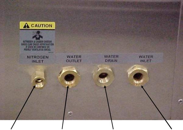
2.(Nitrogen models only) Connect the nitrogen supply line to the inlet marked nitrogen on the side of the oven. The nitrogen supply should run at 70 PSI but not more than 80 PSI. Check for leaks.
3.(Nitrogen and Water Cooled Models) Install water connection for cooling coils to the inlet marked "Water Inlet." Verify the valve on the flow meter is turned off
(fully clockwise). The water supply to the oven must not exceed 100 PSI. It is recommended to install a regulator to prevent any surge. Check for leaks. Slowly open the valve on the flowmeter and allow any air to bleed out. Failure to do this will result in damage to the flowmeter. Repeat this procedure if water supply is shut off. Adjust the flowmeter to 3 gpm (recommended amount of flow.
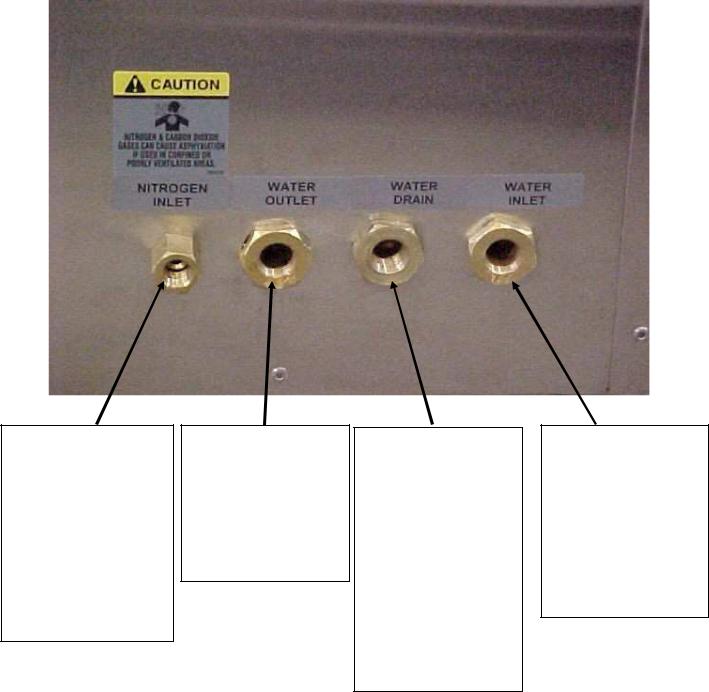
4.(Nitrogen Models only) Make the drain connection at the side of the oven. Note there are two drain connections: water outlet and water drain (see photo on next page). NOTE: The water outlet may be connected in a closed loop system, but the water drain must be left in an open-to-atmosphere condition.
CAUTION: Design the drain system to prevent operator injury from high temperature or pressure buildup. Piping must be able to withstand short periods of up to 500 °F
(260 °C) temperatures [662 °F (350 °C) for LCD ove ns]. Drain lines should be 8
insulated or warning labels installed stating that a hazard exists.
WARNING:
Never allow drain to be plugged as a hot oven will generate a small amount of steam when the water is first turned on. Steam burns.
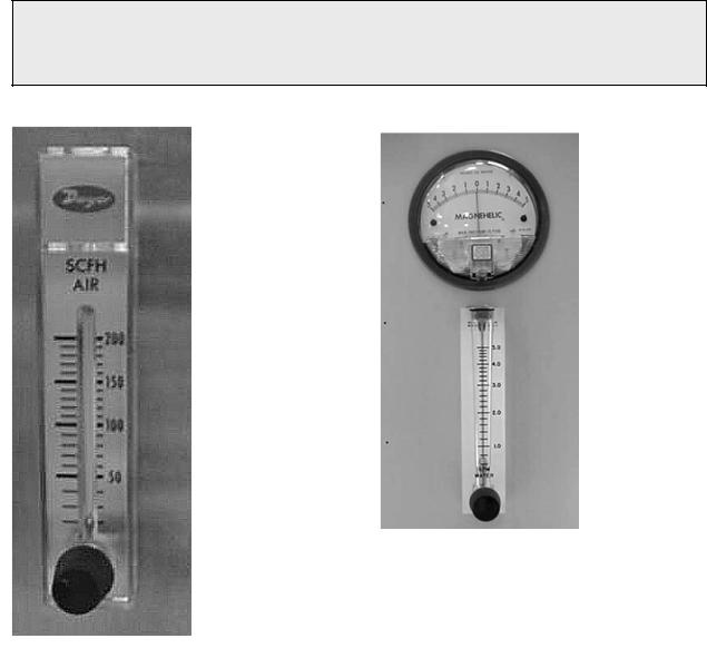
Magnehelic Gauge, Flowmeters
Nitrogen Flow Meter
9
LCC/LCD1-16 & 51-3 WITH WATER COOLING UTILITY CONNECTIONS
Nitrogen or Clean |
|
During cooling cycle, |
|
At the end of a cooling |
|
Water Inlet for cooling. |
Dry Air Inlet. |
|
water flows through the |
|
cycle, Nitrogen or Clean |
|
3/8” NPT female brass |
70 to 80 PSI (4.83 to |
|
water coil and out this |
|
Dry Air is purged |
|
connections are |
5.52 Bar). |
|
connection. |
|
through the water coil. |
|
provided. |
Used to purge water |
|
3/8” NPT female brass |
|
Water and pressurized |
|
|
out of the coil prior to |
|
connections are |
|
nitrogen/air exit this |
|
Requires 2 GPM flow at |
heating the oven. |
|
provided. |
|
connection for 30 |
|
61 °F (16 °C) to meet |
1/4” NPT female |
|
Piping must be rated for |
|
seconds. Must be |
|
published cooling rates. |
brass connections |
|
up to 250 °F (121 °C) |
|
connected to gravity |
|
|
are provided. |
|
|
|
style drain (no |
|
MAXIMUM PRESSURE |
|
|
|
|
backpressure). |
|
100 PSI (6.89 Bar) |
|
|
|
||||
|
|
|
|
3/8” NPT female brass |
|
|
|
|
|
|
connections are |
|
|
|
|
|
|
|
|
|
|
|
|
|
provided. |
|
|
|
|
|
|
Piping must be rated for |
|
|
|
|
|
|
up to 250 °F (121 °C) |
|
|
|
|
|
|
|
|
|
10
LCC/LCD1-16N & 51N-3 UTILITY CONNECTIONS
Nitrogen or Clean Dry Air Inlet.
70 to 80 PSI (4.83 to 5.52 Bar).
Used for Nitrogen/Clean Dry Air Purge and Maintain Inlet and to purge water out of the coil prior to heating the oven.
3/8” NPT female brass connections are provided.
During cooling cycle, water flows through the water coil and out this connection.
3/8” NPT female brass connections are provided.
Piping must be rated for up to 250 °F (121 °C)
At the end of a cooling cycle, Nitrogen or Clean Dry Air is purged through the water coil. Water and pressurized nitrogen/air exit this connection for 30 seconds. Must be connected to gravity style drain (no backpressure).
3/8” NPT female brass connections are provided.
Piping must be rated for up to 250 °F (121 °C)
Water Inlet for cooling. 3/8” NPT female brass connections are provided.
Requires 3 GPM flow at 61 °F (16 °C) to meet published cooling rates.
MAXIMUM PRESSURE
100 PSI (6.89 Bar)
11
LCC/LCD/LLC/LLD1-16-3 AND LCC/LCD/LLC/LLD1-51-3 EXHAUST
(ALL SERIES)
Exhaust located on left side of oven, towards the
Exhaust Stack Must Be Rated for These
Conditions:
SIZE: 1.88” x 2.88” (4.8 cm x 7.3 cm)
FLOW: LCC/LCD/LLC/LLD1-16-3 (all series) = 35 CFM (1 CLM)
FLOW: LCC/LCD/LLC/LLD1-51-3 (all series) = 73 CFM (2 CLM)
TEMPERATURE: LCC/LLC: 500 °F (260 °C)
TEMPERATURE: LCD/LLD: 662 °F (350 °C)
12

STACKABLE LCC-LCD-LLC POWER CONNECTION
|
DOOR LOCK |
Power connection at |
|
Disconnect Switch |
|
on equipment panel |
|
behind front swing |
Ground Buss |
panel |
Panduit to protect line wire between conduit and disconnect switch.
FRONT EQUIPMENT MOUNTING PANEL
FRONT SWING PANEL (CONTROL PANEL)
Conduit for power wires run from rear to behind this panel
13

FRONT SWING PANEL (CONTROL PANEL)
FRESH AIR |
|
EXHAUST |
INLET |
|
FAN |
|
|
|
½” conduit for customer wiring from rear compartment
Slot in
Chassis
REAR COMPARTMENT –
PANEL REMOVED
14
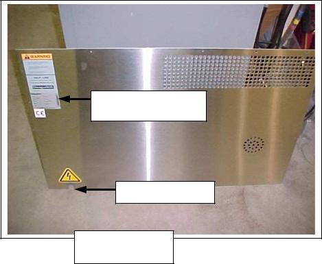
Equipment |
nameplate |
Conduit slot |
REAR PANEL |
15

Wiring
NOTE that the oven must be directly hardwired to the disconnect switch on the equipment panel. Please see the picture for the wiring conduit (rear
and front). A conduit opening is provided at the rear of the oven. A conduit run is provided from the rear oven equipment area to the front equipment panel, through which line voltage power wiring can be connected to the disconnect switch labeled line connection in the front of panel. Consult the electrical drawings included with the oven for wiring details.
Inlet of line voltage power
Rear View of Wiring Conduit
Load break switch |
Outlet of line voltage |
||
power (connect to the |
|||
|
|
||
(line connection) |
|||
main disconnect switch) |
|||
|
|
||
Front View of Wiring Conduit
16

HEPA Filter Installation
Model numbers that begin with the designation LL*1-* are without HEPA filter. If your oven is a LLC*-3 or LLD*-3, disregard instructions of the HEPA filter.
Technicians responsible for installing the filter should use caution. The filter is delicate and must not be damaged during installation. Any filter unit dropped, whether or not in the carton, should be examined for damage. Equally important, the filter unit must be installed so that unfiltered air will not leak past the unit.
NOTE: Make certain that power is disconnected from the oven before removing or replacing the HEPA filter.
1.Remove the filter from the carton.
a.Place the carton on the floor. The floor must be clear of nuts, bolts, and similar protrusions, which would damage the face of the unit. Do not drop or jar the carton.
NOTE: Repairing the damaged filter unit, particularly the medium, should not be attempted by the user. Any unit so repaired must be retested to assure that hidden damage does not exist which will reduce filtering efficiency.
Repair and retest is uneconomical for most users.
b.Tilt the carton on one corner. Be sure to handle the carton at opposing corners.
c.Remove the sealing tape and fold the flaps of the carton back.
d.Gently upend the filter to place the exposed end of the filter on the floor. Do not jar the filter.
e.Pull the carton from the filter unit. Do not pull the filter from the carton.
2.Inspect the filter. Use a strong lamp to examine the exposed areas of both faces to assure that no breaks, cracks, or pinholes are evident. A flashlight, can be used in a darkened room.
∙Look for visible defects with the light projected along the full length of each channel created by the separators. Translucent spots may not necessarily indicate holes or cracks but may simply be variations in thickness of the filter medium.
∙Check that the adhesive seal around the filter unit faces are complete and unbroken.
17

∙Check the corner joints of the frame for adhesive sealing and tightness.
∙Check that the gaskets are cemented firmly to the filter frame and that the gasket pieces are butted or mated at the joints.
3.Pull the shelf out from the oven and set it aside.
NOTE: Make certain that power is disconnected from the oven before removing or replacing the HEPA filter.
4.Loosen the two screws at the upper and lower corners of the right rear of the chamber. Pull out the shelf support/duct as a single unit and set it aside.
5.Note the position of the threaded rods behind the duct assembly on the right side. The HEPA filter will be fitted over these rods.
6.Remove the brass nuts and washers from the rods that are temporarily locking the rods to the oven wall. These nuts will be reused to hold the filter in place.
(LCC1-16 only: Remove filter frame to be reinstalled after filter.)
7.(LCC1-16 only:) Remove the HEPA filter (shipped separately) from its container.
NOTE: The seal side goes toward the wall of the oven. Place it inside the chamber and install filter mounting frame over rods. Push filter tight to rear wall with mounting frame.
(LCC1-51 only:) Remove the HEPA filter (shipped separately) from its container. NOTE: The seal side goes toward the wall of the oven. Place it inside the chamber and install filter mounting angles (shipped separately) over rods. Push filter tight to rear wall with mounting angles.
8.Reinstall the washers and brass nuts to tighten the filter frame down. Tighten the four nuts alternately for even tightness. Be careful not to over tighten. Correct installation torque is 28 +/- 3 in-lbs. Be sure to compress the gasket evenly and equally at all points with the filter frame completely covering the opening.
9.Reinstall the shelf support/duct assembly using the two screws removed earlier.
10.Reinstall the oven shelf.
HEPA Filter Burn-off
The burn-off process will take place in any piece of equipment where a new HEPA filter
18
is used at temperatures above 180°C / 356°F. There will be smoke, possibly a pungent odor, and a light residue on interior surfaces. This is the result of oxidation of the binder. Most of the binder will leave the filter after running at a temperature of 260°C/500°F for 48 (forty-eight) hours. Check the oven for particles or the exhaust for smoke and odor to determine that the process is finished.
Select a location for this process where the smoke and odor generated will be ventilated with the least amount of interruption and inconvenience. Ideally this will be in the final location for the oven. However, it may be a receiving dock, some well ventilated space or even outside if the weather is acceptable. If this location is a very clean area, then special attention must be given to an exhaust hook-up that will capture the smoke and odor. The post-cleaning (i.e. oven wipe down) may also generate dust, and care should be taken if this is done in a clean room.
The following procedure is recommended:
1.Locate the equipment exhaust opening where chamber air is being expelled.
If the oven filter is burned off in a clean area, be sure to handle the equipment exhaust appropriately. If the equipment is large and the exhaust stack is a permanent service connection, it should be connected before the burn-off process is run. If the equipment is small with no permanent exhaust duct required, arrange a temporary connection out of the clean area that will handle the maximum temperature of the equipment. Direct the smoke and odor outside, or to a highly ventilated area.
2.Set the temperature control at the maximum process temperature.
∙ Silicone: Ramp at 1.25° C/min to 260° C and soak for 48 hours.
∙Media Pack: Ramp at 1.25° C/min to 260° C and soa k for 48 hours.
∙ Termikfil: Ramp at 5° C/min to 350° C and soak for 48 hours.
3.Start the fan after making the electrical power connections.
4.Energize the equipment heater.
Use enough fresh air to remove the smoke, while still being able to achieve and maintain the necessary temperature. The completion of the burn-off period should be based on the particle level in the oven or smoke-free exhaust and minimal odor level.
The filter hold-down nuts should be checked after burn-off and tightened again if necessary. For best oven particle control, this step should be repeated on a regular basis.
19

NOTE: If it is necessary to move the equipment after the burn-off process, considerable care should be used. The binder which gives strength to new filters is now burned-off and the media is very fragile. Rough handling of either the filter alone or the equipment with the filter installed is not recommended as it may tear the media and lead to reduced filter efficiency. Removal of the filter after heating can also result in damage to the frame seal, and is only recommended when replacing the filter.
20
OVEN OPERATION
Oven
The stackable LCC oven is a class 100 clean room oven with HEPA (High Efficiency
Particulate Air) filtration. This oven is ideal for processes where minimization of contamination is essential.
Forced convected airflow provides rapid uniform distribution of heat. A HEPA (High Efficiency Particulate Air) filter is mounted in a stainless steel frame in the
supply plenum. These filters are 99.97% effective in filtering 0.3 micron particles.
The cooling fan, is controlled on/off by an event relay in the Protocol Plus Control. The cooling fan is used for rapid cool-down at the end of the process cycle, or to maintain low temperature setpoints during process cycle. It may also be turned on at the start of a process cycle to assure that starting temperature is less than 70° C.
The nitrogen models have stainless steel water coil which permits rapid cool down and lower temperature operation. The nitrogen oven comes with an adjustable flowmeter a for adjusting purge rate, and needle valve for setting maintain rate, separate solenoid valves for purge and maintain operation and a pressure relief exhaust port. An exhaust fan which powers on whenever the oven is running maintains consistent chamber pressure control with varied exhaust stack conditions.
The oven has a type 304-2B stainless steel interior and a type 304-#4 stainless steel interior. All interior seams are continuously welded on the insulation side. This protects the work chamber from contaminated air and permits chamber washing without damaging the insulation. Interior ductwork may be easily removed for cleaning. Heater frame, fan wheel and motor shaft are constructed of stainless steel.
All controls are mounted on the front of the oven for easy operation and readability.
Two electropolished stainless steel wire shelves are provided. The shelves are removable and adjustable on two inch centers.
21
 Loading...