


LAC – 6 SERIES
WITH PROTOCOL PLUS ™ INSTRUCTION MANUAL
C-194
PN 150138 REVISION O
1/2009

Notice
Users of this equipment must comply with operating procedures and training of operation personnel as required by the Occupational Safety and Health Act (OSHA) of 1970, Section 6 and relevant safety standards, as well as other safety rules and regulations of state and local governments. Refer to the relevant safety standards in OSHA and National Fire Protection Association (NFPA), section 86 of 1990.
Caution
Setup and maintenance of the equipment should be performed by qualified personnel who are experienced in handling all facets of this type of system. Improper setup and operation of this equipment could cause an explosion that may result in equipment damage, personal injury or possible death.
Thank you for choosing Despatch Industries. We appreciate the opportunity to work with you and to meet your heat processing needs. We believe that you have selected the finest equipment available in the heat processing industry.
At Despatch, our service does not end after the purchase and delivery of our equipment. For this reason we have created the Service Products Division within Despatch. The Service Products Division features our Response Center for customer service. The Response Center will direct and track your service call to ensure satisfaction.
Whenever you need service or replacement parts, contact the
Response Center at 1-800-473-7373: FAX 612-781-5353.
Thank you for choosing Despatch.
Sincerely,
Despatch Industries


PREFACE
This manual is your guide to the Despatch oven. It is organized to give you the information you need quickly and easily.
The INTRODUCTION section provides an overview |
|
NOTE: |
|
|
|
||
|
Read the entire |
|
|
of the Despatch oven. |
|
|
|
|
INTRODUCTION and THEORY |
|
|
|
|
|
|
|
|
OF OPERATION before |
|
The THEORY OF OPERATION section details the |
|
installing the oven. |
|
function and operation of assemblies and subassem- |
|
|
|
blies on the Despatch oven. |
|
|
|
|
|
||
The INSTRUCTIONS and CONTROL sections provide directions on unpacking, installing, operating and maintaining the Despatch oven.
An efficient way to learn about the oven would be to read the manual while working with the corresponding oven control system. This will give you practical hands-on experience with information in the manual and the oven.
Before operating the equipment, be sure you understand all of the technical information contained in this manual. Information skipped, not understood or misunderstood could create the possibility of operating the equipment in an unsafe manner. This can cause damage to the oven or personnel or reduce the efficiency of the equipment.
WARNING:
Failure to heed warnings in this instruction manual and on the oven could result in personal injury, property damage or death.
i
Revision B: |
Updated contents of DRAWINGS section |
|
Updated Protocol Plus instructions |
Revision C: |
Added “Operating Environment” note to Operating section |
|
Updated drawings |
|
Modified Preface |
Revision D: |
Modified per Rev C Protocol Plus software |
Revision E: |
Various corrections |
Revision F: |
Updated drawings |
Revision G: Updated Despatch Warranty |
|
Revision H: |
Updated drawing |
Revision I: |
Update to Protocol Plus Version 4 |
Revision J: |
Ref. CAR 1165C |
Revision K: |
Changes to Unpacking and Inspection |
Revision L: |
Changed drawings |
Revision M: |
Revised Protocol numbers. Updated Despatch address |
Revision N: |
Updated warranty |
Revision O: |
Updated Protocol Plus Section |
ii
TABLE OF CONTENTS |
|
INTRODUCTION ....................................................................................................................... |
1 |
Special Features ............................................................................................................ |
1 |
Specifications ................................................................................................................. |
2 |
Dimensions ......................................................................................................... |
2 |
Capacities ........................................................................................................... |
3 |
Temperature ....................................................................................................... |
3 |
Power ................................................................................................................. |
4 |
THEORY OF OPERATION ........................................................................................................ |
5 |
Damper Control .............................................................................................................. |
6 |
Determining Damper Settings ............................................................................. |
6 |
Full Closed Position................................................................................. |
6 |
Full Open Position ................................................................................... |
7 |
Other Damper Settings............................................................................ |
7 |
INSTRUCTIONS ........................................................................................................................ |
8 |
Unpacking and Inspection .............................................................................................. |
8 |
Installation and Set-up.................................................................................................... |
9 |
Operating ...................................................................................................................... |
10 |
Operating Environment ...................................................................................... |
10 |
Loading the Oven............................................................................................... |
11 |
Pre-Startup Checklist ......................................................................................... |
12 |
Startup ............................................................................................................... |
13 |
CONTROL ................................................................................................................................ |
14 |
Theory of Control Operation .......................................................................................... |
14 |
Operating Modes ............................................................................................... |
16 |
Setup Mode ....................................................................................................... |
16 |
Fast Start Mode ................................................................................................. |
16 |
High Limit........................................................................................................... |
17 |
Indicators ........................................................................................................... |
17 |
Displays ............................................................................................................. |
18 |
Key Functions .................................................................................................... |
18 |
Outputs .............................................................................................................. |
19 |
Relay (Continued) .............................................................................................. |
20 |
Communication.................................................................................................. |
20 |
Optional Software .............................................................................................. |
20 |
INSTRUCTIONS ....................................................................................................................... |
21 |
Start-Up......................................................................................................................... |
21 |
Operation ...................................................................................................................... |
22 |
Manual Mode ..................................................................................................... |
22 |
Timer Mode........................................................................................................ |
23 |
Profile Mode....................................................................................................... |
24 |
Auto Start Mode ................................................................................................. |
24 |
Setup Mode ....................................................................................................... |
25 |
Instructions for Setup Mode Pages................................................................................ |
26 |
Program Page.................................................................................................... |
26 |
Sample Profile ................................................................................................... |
29 |
Auto Start Page ................................................................................................. |
30 |
PID Page ........................................................................................................... |
32 |
iii
Control Page...................................................................................................... |
33 |
Communication Page (optional) ......................................................................... |
34 |
Real Time Clock Page ....................................................................................... |
34 |
Relay Outputs Page (optional) ........................................................................... |
35 |
Test Page .......................................................................................................... |
36 |
Zone Calibration Page ....................................................................................... |
37 |
Sensor Calibration Page .................................................................................... |
39 |
Enable Page ...................................................................................................... |
41 |
Digital Inputs (optional) ...................................................................................... |
42 |
Error Messages and Alarms .......................................................................................... |
43 |
Quick Reference and Default Values............................................................................. |
44 |
Technical Specifications ................................................................................................ |
51 |
MAINTENANCE........................................................................................................................ |
52 |
Checklist........................................................................................................................ |
52 |
Tests ............................................................................................................................. |
53 |
Replacement ................................................................................................................. |
54 |
Parts .................................................................................................................. |
54 |
Protocol Plus™ Instrument ............................................................................................ |
55 |
Heater Unit .................................................................................................................... |
55 |
Fan Motor...................................................................................................................... |
56 |
TROUBLESHOOTING .............................................................................................................. |
58 |
DRAWINGS .............................................................................................................................. |
60 |
APPENDIX................................................................................................................................ |
67 |
Temperature Scale Conversion (C/F) ............................................................................ |
67 |
Optional MRC5000 Recorder Setup .............................................................................. |
68 |
iv

INTRODUCTION
This section provides an overview of the Despatch LAC-6 Series forced air oven. The LAC-6 Series Ovens have the most effective heat distribution and the fastest processing time of any lab oven their size. Air is discharged from the left side wall of the oven and circulates through the chamber.
Special Features
The sturdy construction and three inch insulation of the Despatch LAC-6 Series ovens contribute to excellent temperature uniformity.
Other special features include the following:
Unique Despatch design to combine higher fan volume of forced recirculated air with a system of perforated stainless steel walls for the ultimate in temperature uniformity.
Welded double wall construction and fiberglass insulation to reduce heat loss. Silicone rubber gaskets further minimize heat leakage.
Rapid response heater.
Scratch-resistant baked enamel exterior and stainless steel interior for easy cleaning.
Space-saving, stackable design.
Simple pull-open door with “no-hands” closing
1
Specifications
Dimensions
|
LAC |
|
|
Chamber Size |
|
|
Capacity |
|
|
Overall Size |
|
|
Max. |
|
|
Exhaust Diameter |
|
||||||||||||
|
|
|
|
|
|
|
|
|
|
|
|
||||||||||||||||||
|
|
|
|
|
|
||||||||||||||||||||||||
|
|
|
|
|
in (cm) |
|
|
|
|
|
|
|
|
in (cm) |
|
|
|
|
Number of |
|
|
|
|||||||
|
Model |
|
|
|
|
|
|
|
|
feet3 |
|
|
|
|
|
|
|
|
|
|
Located on Back |
|
|||||||
|
|
|
|
|
|
|
|
|
|
|
|
|
|
|
|
|
|
|
|
|
|
Shelf |
|
||||||
|
No. |
|
|
W* |
|
|
D |
|
|
H |
|
|
(liters) |
|
|
W |
|
|
D |
|
|
H |
|
|
|
|
of Chamber (in) |
|
|
|
|
|
|
|
|
|
|
|
|
|
|
|
|
|
|
|
Positions |
|
|
|
|||||||||
|
|
|
|
|
|
|
|
|
|
|
|
|
|
|
|
|
|
|
|
|
|
|
|||||||
|
|
|
|
|
|
|
|
|
|
|
|
|
|
|
|
|
|
|
|
|
|
|
|
|
|
|
|
|
|
|
|
|
|
|
|
|
|
|
|
|
|
|
|
|
|
|
|
|
|
|
|
|
|
|
|
|
|
|
|
1-10 |
|
13.75 |
|
12 |
|
12 |
|
1 |
|
23 |
|
19 |
|
29.5 |
|
5 |
|
1 |
|
||||||||||
|
|
|
(35) |
|
(31) |
|
(31) |
|
(33) |
|
(58) |
|
(48) |
|
(75) |
|
|
|
|
|
|
|
|||||||
1-38A |
18.75 |
|
18 |
|
19 |
|
3.7 |
|
28 |
|
25 |
|
35.5 |
|
9 |
|
2½ |
|
|||||||||||
|
|
|
(48) |
|
(46) |
|
(48) |
|
(105) |
|
(71) |
|
(64) |
|
(90) |
|
|
|
|
|
|
|
|||||||
1-38B |
18.75 |
|
18 |
|
19 |
|
3.7 |
|
28 |
|
25 |
|
35.5 |
|
9 |
|
2½ |
|
|||||||||||
|
|
|
(48) |
|
(46) |
|
(48) |
|
(105) |
|
(71) |
|
(64) |
|
(90) |
|
|
|
|
|
|
|
|||||||
1-67 |
|
23.75 |
|
20 |
|
24 |
|
6.6 |
|
36 |
|
27 |
|
40.5 |
|
11 |
|
2½ |
|
||||||||||
|
|
|
(60) |
|
(51) |
|
(61) |
|
(187) |
|
(91) |
|
(69) |
|
(103) |
|
|
|
|
|
|
|
|||||||
2-12 |
|
23.75 |
|
24 |
|
36 |
|
12 |
|
36 |
|
31 |
|
52.5 |
|
17 |
|
2 - 2½ |
|
||||||||||
|
|
|
(60) |
|
(61) |
|
(91) |
|
(336) |
|
(91) |
|
(79) |
|
(133) |
|
|
|
|
|
|
|
|||||||
2-18 |
|
35.25 |
|
24 |
|
36 |
|
18 |
|
48 |
|
31 |
|
52.5 |
|
17 |
|
2 - 2½ |
|
||||||||||
|
|
|
(91) |
|
(61) |
|
(91) |
|
(500) |
|
(122) |
|
(79) |
|
(133) |
|
|
|
|
|
|
|
|||||||
|
|
|
|
|
|
|
|
|
|
|
|
|
|
|
|
|
|
|
|
|
|
|
|
|
|
|
|
|
|
* Allow 0.5" clearance on each side for shelf supports.
2
Capacities
|
LAC Model Number |
|
|
1-10-6 |
|
|
1-38 A-6 & |
|
|
1-67-6 |
|
|
2-12-6 |
|
|
2-18-6 |
|
|
|
|
|
|
|
|
|
|
|
|
|
|
|||||||
|
|
|
|
|
|
|
|
B-6 |
|
|
|
|
|
|
|
|
|
|
|
|
|
|
|
|
|
|
|
|
|
|
|
|
|
|
|
|
|
Maximum Load |
Lbs |
150 |
|
175 |
|
250 |
|
300 |
|
300 |
|
|||||||
Maximum Shelf Load |
Lbs |
50 |
|
50 |
|
50 |
|
50 |
|
50 |
|
|||||||
Exhaust |
CFM |
|
Adjustable |
|
Adjustable |
|
Adjustable |
|
Adjustable |
|
Adjustable |
|
||||||
|
|
|
|
|
to 5 |
|
to 12 |
|
to 12 |
|
to 30 |
|
to 40 |
|
||||
Recirculating Fan |
CFM |
150 |
|
300 |
|
300 |
|
600 |
|
600 |
|
|||||||
|
|
H.P. |
1/25 |
|
¼ |
|
¼ |
|
|
¼ x 2 |
|
¼ x 2 |
|
|||||
Approx. Weight Net |
Lbs |
110 |
|
185 |
|
255 |
|
360 |
|
450 |
|
|||||||
|
|
KG |
50 |
|
84 |
|
115 |
|
164 |
|
205 |
|
||||||
Shipping Weight |
Lbs |
175 |
|
270 |
|
360 |
|
480 |
|
600 |
|
|||||||
|
|
KG |
80 |
|
124 |
|
163 |
|
217 |
|
271 |
|
||||||
|
|
|
|
|
|
|
|
|
|
|
|
|
|
|
|
|
|
|
Temperature
|
LAC-6 Model Number |
|
|
1-10 |
|
|
1-38 A |
|
|
1-38 B |
|
|
1-67 |
|
|
2-12 |
|
|
2-18 |
|
|
|
|
|
|
|
|
|
|
|
|
|
|
|
|
||||||||
|
|
|
|
|
|
|
|
|
|
|
|
|
|
||||||||
Time to Temperature |
40ºC – 100ºC |
8 |
|
9 |
|
6 |
|
6 |
|
6 |
|
4 |
|
||||||||
(approximate minutes |
40ºC – 200ºC |
25 |
|
32 |
|
22 |
|
20 |
|
19 |
|
17 |
|
||||||||
with no load) |
40ºC – 260ºC |
40 |
|
60 |
|
36 |
|
34 |
|
31 |
|
29 |
|
||||||||
|
|
|
|
|
|
|
|
|
|
|
|
|
|
||||||||
Recovery Time - Door Open |
100ºC |
1 |
|
1 |
|
1 |
|
1 |
|
1 |
|
1 |
|
||||||||
One Minute (approximate |
|
200ºC |
3 |
|
6 |
|
4 |
|
3 |
|
6 |
|
4 |
|
|||||||
minutes with no load) |
|
260ºC |
7 |
|
14 |
|
8 |
|
5 |
|
9 |
|
8 |
|
|||||||
|
|
|
|
|
|
|
|
|
|
|
|
|
|
|
|
|
|
|
|||
Temperature Uniformity at |
|
100ºC* |
|
±1.5ºC |
|
|
|
|
|
|
|
±1ºC |
|
|
|
|
|
|
|||
|
|
|
200ºC* |
|
±3ºC |
|
|
|
|
|
|
|
±2ºC |
|
|
|
|
|
|
||
|
|
|
260ºC* |
|
±4ºC |
|
|
|
|
|
|
|
±2.5ºC |
|
|
|
|
|
|
||
|
|
|
|
|
|
|
|
|
|
|
|
|
|
|
|
||||||
Operating Range with 20ºC Ambient |
|
40ºC – 260ºC |
|
|
|
|
|
|
|
|
|
|
|
|
|||||||
|
|
|
|
|
|
|
|
|
|
|
|||||||||||
Control Stability |
|
|
|
±0.5ºC per 5ºC change in ambient |
|
|
|
|
|
|
|||||||||||
|
|
|
|
|
|
|
|
|
|
|
|
|
|
|
|
|
|
|
|
||
Repeatability |
|
|
|
±0.5ºC |
|
|
|
|
|
|
|
|
|
|
|
|
|
|
|
||
|
|
|
|
|
|
|
|
|
|
|
|
|
|
|
|
|
|
|
|
|
|
*Figures are based on actual tests in an empty oven. Uniformity can vary slightly depending on unit and operating conditions.
3

Power
Line voltages may vary in some geographical locations. If your line voltage is much lower than the oven voltage rating, warm up time will be longer and motors may overload or run hot. If your line voltage is higher than name plate rating, the motor may run hot and draw excessive amps.
If the line voltage varies more than 10% from the oven voltage rating, some electrical components such as relays, temperature controls, etc. may operate erratically.
Power Requirements |
|
|
|
|
|
|
Model |
Volts |
Amps |
Hertz |
Phase |
Heater |
Cord and Plug |
|
|
|
|
|
KW |
|
LAC 1-10-6 |
120 |
10.0 |
50/60 |
1 |
1 |
Included, 15 Amp (NEMA 5-15) |
LAC 1-38A-6 |
120 |
16.5 |
50/60 |
1 |
1.6 |
Included, 20 Amp (NEMA 5-20) |
LAC 1-38B-6* |
240 |
9.5 |
50/60 |
1 |
1.8 |
Included, 15 Amp (NEMA 6-15) |
LAC 1-67-6* |
240 |
12.0 |
50/60 |
1 |
2.4 |
Included, 15 Amp (NEMA 6-15) |
LAC 2-12-6* |
240 |
18.5 |
50/60 |
1 |
3.6 |
None, Hardwired |
LAC 2-18-6* |
240 |
23.5 |
50/60 |
1 |
4.8 |
None, Hardwired |
*Oven designed for 240 volts (see name plate on oven) will operate satisfactorily on a minimum of 208 volts, but with a 25% reduction in heater power. If your power characteristics are lower, contact Despatch Industries. An option is available to regain the full heater power when operating on 208V.
The LAC 2-12-6 and LAC 2-18-6 must be hardwired to the electric supply using 10 AWG or larger wires suitable for at least 75ºC (167ºF).
4
THEORY OF OPERATION
This section details the function and operation of assemblies and subassemblies on the Despatch LAC-6 Series Ovens. These ovens have the most effective heat distribution system and the fastest processing time of any lab oven its size. They are especially useful for testing, preheating, sterilizing, drying, aging and curing as well as other production applications. Horizontal airflow with precision digital control delivers uniform, fast processing. The overall result is efficient productivity under strenuous conditions.
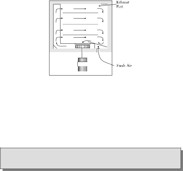
Airflow Pattern in LAC Series Oven
The unique Despatch computerized design, moves forced convected heat through perforated stainless steel walls. The air is recirculated with a high volume fan. Despatch LAC-6Series Ovens employ higher volume fans than any competitive model. The chamber can be densely loaded without interfering with the process. Air delivery temperature is within 1ºC of the number appearing on the digital display. Fresh air intake is regulated by a panel-mounted damper control, while the exhaust opening is fixed. The exhaust port, on the back of the oven, is covered by a hat bracket.
WARNING
Do not remove the hat bracket as it distributes exhaust air and protects the exhaust opening from being completely covered.
5
Damper Control
The oven is equipped with a manually adjustable damper mechanism. The damper control arm is located on the front panel of the oven. The damper adjustment controls the fresh air opening which, due to pressurization of the oven chamber, controls the flow of exhaust. If the damper is in the full open position, the maximum exhaust rate is achieved. If the damper is in the fully closed position, the minimum exhaust rate is achieved.
Determining Damper Settings
The optimum setting for the damper depends on several factors. These factors include ambient environment temperature, load conditions, load distribution, heat up rates, cool down rates, desired temperature uniformity and most importantly the desired operating temperature. To consider all of these variables at any one point in time is not practical and there are engineering tradeoffs that should be considered. Therefore guidelines should be used to determine the damper setting.
In general, the damper should be set so that the amount of fresh air flowing into and exhausting from the chamber agrees with the desired operating temperature conditions. The following outline shows the considerations involved with various damper position settings.
Full Closed Position
When the damper is in the full closed position, the chamber will be able to achieve the maximum attainable heat up rates for the chamber. In addition, the chamber will use the minimum amount of power to operate at the desired temperature. In almost all cases, the damper should be in the full closed position in order to efficiently operate at the maximum operating temperature for the chamber.
6
Full Open Position
When the damper is in the full open position, the chamber will operate at its minimum operating temperature.
Friction heat from the air recirculation system builds up in the chamber. This causes chamber temperature to rise slightly even though the heating system is not turned on. After the recirculation motor has been on for an extended period of time, the chamber will reach a thermal equilibrium temperature.
When the damper is not set to the full open position, the chamber has no way to readily dissipate the heat generated by the friction. With the damper fully open, the thermal equilibrium temperature is the minimum operating temperature of the chamber.
Other Damper Settings
The damper can be set to several other distinct operating positions. In most cases the damper setting is influenced by two specific performance factors. The two performance factors are uniformity and cool down rates.
The uniformity of the chamber is influenced by the inside chamber pressure of the system. The pressure inside the chamber is dependant on the amount of fresh air flowing into the chamber. When a large volume of fresh air is flowing into the chamber, the chamber becomes slightly pressurized and the overall temperature uniformity improves. The slightly pressurized chamber produces the effect of "pushing" the air to the corners of the chamber. Typically the corners of the chamber will improve with respect to temperature distribution while the core of the chamber will maintain excellent uniformity characteristics regardless of the damper position. Therefore, the pressurization of the chamber typically is a factor when the chamber is loaded heavily. The best uniformity results, with respect to the product, are achieved when no more than two-thirds of any inside chamber dimension are used. The best overall results are achieved when the product(s) are located in the center of the chamber.
NOTE: Over-pressuring the chamber can cause hot air to blow out around the door seal and cause the area around the door to be hot to the touch. To eliminate this hot air from entering the room, close the damper slightly until the air stops blowing.
7

INSTRUCTIONS
The INSTRUCTIONS section provides directions for unpacking, installation, operation and maintenance of the LAC-6 Series oven.
Unpacking and Inspection
Remove all packing materials and thoroughly inspect the oven for damage of any kind that could have occurred during shipment.
See whether the carton and plastic cover sheet inside carton are still in good condition.
Look at all outside surfaces and corners of the oven for scratches and dents.
Check the oven controls and indicators for normal movement, bent shafts, cracks, chips or missing parts such as knobs and lenses.
Check the door and latch for smooth operation.
If there is damage that may have occurred during shipment, follow these instructions.
1.Contact the shipper immediately and file a written damage claim.
2.Contact Despatch Industries to report your findings and to order replacement parts for those that were damaged or missing.
3.Send a copy of your filed damage claims to Despatch.
4.Next, check to make sure you have received all the required materials. Your shipment should include:
One (1) Despatch oven,
One (1) Instruction manual,
One (1) Warranty card,
Two (2) Shelves
8

5.If any of these items are missing from the packaged contents, contact Despatch Industries to have the appropriate materials forwarded to you.
6.Finally, to protect the warranty on your new LAC-6 Series Oven, complete the warranty card and mail it to Despatch within 15 days after receipt of the equipment.
Installation and Set-up
1. |
Place oven on a bench top or an optional |
|
WARNING: |
|
|
||||
|
cabinet base. |
|
|
|
|
|
Do not use the oven in wet, |
|
|
|
|
|
|
|
|
The oven must have a minimum of two (2) |
|
corrosive or explosive |
|
|
|
atmospheres unless this oven is |
|
|
|
inches clearance in the rear to provide proper |
|
specifically designed for a |
|
|
ventilation. The oven may be placed next to |
|
special atmosphere. |
|
|
another cabinet, or next to another oven, with |
|
|
|
|
|
|
|
|
|
three (3) inch clearance (the doors will still open). |
|
|
|
|
Make sure oven is level and plumb; this will |
|
|
|
|
assure proper heat distribution and operation |
WARNING: |
||
|
of all mechanical components. |
All grounding and safety |
||
|
|
|
equipment must be in compli- |
|
2. |
Identify correct power source indicated on the |
ance with applicable codes, |
||
|
specification plate. |
ordinances and accepted safe |
||
|
|
|
practices. |
|
3.Plug or hardwire oven directly to the electric supply.
For ovens that need to be hard wired (units without power cord) or where a power cord is shipped loose; the power lines with ground must be run from the rear of the oven to the front and attached to L1 and L2 on the circuit board, located behind the control panel. Access the circuit board by turning the screws counter-clockwise and opening the hinged control panel.
Tighten terminals on the circuit board to 10.6 – 13.2 lb-in. (1.2 – 1.5 Nm). The ground wire will attach to the ground bus on the panel.
For units where the cord is shipped loose, attach the strain relief after cord is wired to the circuit board.
Close the control panel after power supply wires (or cord) is attached.
9

Operating
Users and operators of this oven must comply with operating procedures and training of operating personnel as required by the Occupational Safety and Health Act (OSHA) of 1970, Section 5 and relevant safety standards, and other safety rules and regulations of state and local governments. Refer to the relevant safety standards in OSHA and National Fire Protection Association (NFPA), Section 86 of 1990.
WARNING:
Do not use oven in wet, corrosive or explosive atmospheres unless this oven is specifically designed for a special atmosphere.
Operating Environment
The Despatch oven is designed to operate in an industrial setting. Despatch does recommend the following environmental operating guidelines:
1.The oven is placed on a solid foundation.
2.The oven is not exposed to excessive external vibration.
3.All electrical cabinet covers must remain affixed.
4.Reasonable particulate matter in the atmosphere. Where excessive particulate matter is present, such as on a construction site or coal processing, Despatch recommends periodic (usually monthly) cleaning of all electrical compartments.
5.The power supply is within the specifications provided by Despatch. If the facility power supply is not stable, Despatch recommends a line conditioner.
10
Loading the Oven
Despatch Industries cannot be responsible for either the process or process temperature used, or for the quality of the product being processed. It is the responsibility of the purchaser and operator to see that the product undergoing processing in a Despatch oven is adequately protected from damage.
Carefully following the instructions in this manual will help the purchaser and operator in fulfilling that responsibility.
When loading the oven avoid spills of anything onto the heater elements or onto the floor of the oven. Do not place the load on the oven floor plate. This may cause the load to heat unevenly and the weight may cause shorting out of the heater elements. Use the shelves provided.
The two shelves are designed to be pulled out about half way without tipping for loading and unloading. The support capacity of the shelves is listed in the Capacities Table in the Specifications section in this manual. Do not overload the shelves.
Distribute the workload evenly so that airflow is not restricted. Do not overfill your oven. The workload should not take up more than two-thirds of any dimension of the inside cavity.
11

Pre-Startup Checklist
Know the system. Read this manual carefully. Make use of its instructions and explanations. Safe, continuous, satisfactory, trouble-free operation depends primarily on your understanding the system and your willingness to keep all parts in proper operating condition.
Check line voltage. Voltage must correspond to nameplate requirements of motors and controls. Refer to the section on power connections in the INTRODUCTION of this manual.
Fresh air and exhaust. Do not be careless about restrictions in and around the fresh air and exhaust openings and stacks. Under no condition permit them to become so filled with dirt that they appreciably reduce the air quantity. The proper ventilation clearances should be fulfilled at all times. Refer to the Set-up instructions in this manual.
Ventilation There is an exhaust opening in the rear of the unit that is covered by a hat bracket. Do not remove the hat bracket as it protects the exhaust opening from being completely covered.
Helpful hints
For drying ovens, open vent to prevent buildup of moisture.
For sample heating, close the vent when no ventilation is required.
WARNING
Do not use flammable solvent or flammable material in this oven. Do not process closed containers of any substance or liquid in this oven because they may explode under heat.
12
Startup
For fastest oven heat-up time, close the fresh-air vent. After the desired temperature is reached, the vent may be adjusted as needed.
1.Start Fan.
a.Open oven door.
b.Press Power switch to the On position. You will hear the recirculating fan start.
c.Shut oven door.
d.Check that the control display turns on.
2.Operate the temperature control as desired by following the control operation instructions that follow.
13

CONTROL
The special features of the Protocol PlusTM control include:
PID tuning
Ramp/Soak programming of up to 64 segments
Segment looping and profile linking
Built-in manual reset high limit control
Built-in process timer
Dedicated LED display for process temperature
Multi-purpose two-line LCD display with backlight
Auto-tuning
Security access
Process temperature retransmission signal
Digital inputs for remote profile control
Real time clock
Optional relay outputs for events, alarms, or end-of-cycle signal
Optional RS232/RS422/RS485 MODBUS communications
Theory of Control Operation
The Protocol Plus is a modular microprocessor based digital temperature controller. The Protocol Plus operates as a dual functioning controller/high limit instrument. The control portion utilizes a time-proportioning voltage signal to control heating devices with minimal temperature fluctuations.
The high limit portion protects the product and/or the oven from overheating. If the product being processed has a critical high temperature limit, the high limit setpoint should be set to a temperature somewhat below the temperature at which the product could be damaged. If the product does not have a critical high temperature limit, the high limit setpoint should be set 5 to 15 degrees higher than the maximum programmed setpoint at which the oven will operate.
14
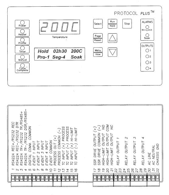
Protocol Plus Faceplate and Wiring Diagram
15
 Loading...