

Page 1

Stackable LCC/LCD Oven Owner’s Manual PREFACE
ULTRAFLEX DRYING AND FIRING
FURNACE
MODELS 1000, 3615, 3630, 3640
C-204
VERSION 26
10/2008
STACKABLE LCC/LCD OVEN
OWNER’S MANUAL
C-195
PN 156452
VERSION 26
09/2010
Version 26 1
All rights reserved. No part of the contents of this manual may be reproduced, copied or transmitted in any form or by any
means including graphic, electronic, or mechanical methods or photocopying, recording, or information storage and
retrieval systems without the written permission of Despatch Industries, unless for purchaser's personal use.
Copyright © 2010 by Despatch Industries.
Page 2
PREFACE Stackable LCC/LCD Oven Owner’s Manual
Revision
Date
Author
Description
B
6/01
Various corrections
C
11/01
Corrections, addition of schematic drawings
D
1/02
Corrections, update of schematic drawings
E
4/02
Update of schematic drawings, modified per
Rev C Protocol Plus software
F
7/02
Corrections to Protocol Plus software
description
G
9/02
Miscellaneous corrections
H
11/02
Modify operating procedure, update schematic
drawings
I
1/03
Update Despatch warranty pages
J
5/03
Update of schematic drawings
K
8/03
Update of schematic drawings
L
11/03
Update to Protocol Plus Version 4.0.
M
12/03
Add door lock manual override and Nitrogen
needle valve information
N
2/04
Update of schematic drawings
P
9/04
Update of schematic drawings
Q
11/04
Update of schematic drawings
R
3/05
Update of schematic drawings
S
6/05
Update Declaration of Conformity
T
12/05
Update Declaration of Conformity, add LLC
notes
U
8/06
Revised Protocol Plus numbers. Updated
Despatch address. Updated CE documents.
V
11/07
Updated warranty
W
12/07
Corrected Nitrogen Inlet connection from 3/8”
to 1/4” X 3/09
Updated Controller Section
Y
2/10
Updated Declaration of Conformity and
drawings
25
7/10
K. Livingston
Revise format
26
9/10
K. Livingston
Remove Protocol Plus to separate manual
2 Version 26
Revision History
All rights reserved. No part of the contents of this manual may be reproduced, copied or transmitted in any form or by any
means including graphic, electronic, or mechanical methods or photocopying, recording, or information storage and
retrieval systems without the written permission of Despatch Industries, unless for purchaser's personal use.
Copyright © 2010 by Despatch Industries.
Page 3

Stackable LCC/LCD Oven Owner’s Manual PREFACE
Version 26 3
Table of Contents
1. About This Manual ................................................................................................. 6
1.1. Important User Information .......................................................................... 6
1.2. Manufacturer & Service ................................................................................ 7
1.3. Organization of this Manual ......................................................................... 7
1.4. Conventions .................................................................................................. 8
1.5. Specifications ................................................................................................ 9
1.5.1. Model Numbering and Naming Conventions ........................................... 9
1.5.2. Dimensions ................................................................................................ 9
1.5.3. Capacities ................................................................................................ 10
1.5.4. Power ....................................................................................................... 10
1.5.5. Temperature ............................................................................................ 11
2. Safety .................................................................................................................... 12
2.1. Safety Information ...................................................................................... 12
2.1.1. Lockout.................................................................................................... 12
2.1.1.1. Lockout Requirements ......................................................................... 12
2.1.1.2. Lockout Procedure ............................................................................... 12
2.1.2. Door and Panel ........................................................................................ 13
2.2. Maintenance ................................................................................................ 13
2.3. Electrical Power .......................................................................................... 13
2.4. Fire .............................................................................................................. 14
2.5. Equipment Lockout Requirements ............................................................. 14
2.5.1. Emergency Stop ...................................................................................... 14
3. Theory of Operation .............................................................................................. 15
3.1. The Stackable LCC/LCD Series Oven ....................................................... 15
3.2. The Protocol Plus Controller ...................................................................... 16
3.3. HEPA Filters ............................................................................................... 17
3.3.1. Definitions ............................................................................................... 17
3.3.2. Filter Packaging, Shipping and Handling ............................................... 17
3.3.3. HEPA Filter Validation Testing .............................................................. 18
3.3.3.1. D.O.P. Testing ..................................................................................... 18
3.3.3.2. Class 100 Testing................................................................................. 18
3.3.3.3. Validation Testing ............................................................................... 19
3.3.3.4. HEPA Filter Burn-off Process Not Necessary .................................... 19
3.3.4. HEPA Filter Unit Replacement ............................................................... 19
3.3.5. HEPA Filter: Magnehelic Pressure Gauge .............................................. 20
4. Assembly & Setup ................................................................................................ 21
4.1. Unpack & Inspect The LCC/LCD Oven ..................................................... 21
4.1.1. If Damaged During Shipping .................................................................. 22
4.2. Set-up The LCC/LCD Oven ....................................................................... 22
4.2.1. Select Oven Location .............................................................................. 22
4.2.1.1. Single Oven Placement Requirements ................................................ 22
4.2.1.2. Multiple Oven Placement Requirement .............................................. 22
4.2.2. Oven Utility Connections ........................................................................ 23
4.2.2.1. Nitrogen With Water-Cooled Models ................................................. 24
All rights reserved. No part of the contents of this manual may be reproduced, copied or transmitted in any form or by any
Copyright © 2010 by Despatch Industries.
means including graphic, electronic, or mechanical methods or photocopying, recording, or information storage and
retrieval systems without the written permission of Despatch Industries, unless for purchaser's personal use.
Page 4

PREFACE Stackable LCC/LCD Oven Owner’s Manual
4 Version 26
4.2.2.2. Air Atmosphere with Optional Water Cooling Model ........................ 25
4.2.3. Exhaust Connections ............................................................................... 27
4.2.4. Wiring & Power Connections ................................................................. 27
4.3. HEPA Filter Installation ............................................................................. 29
4.3.1. HEPA Filter Burn-Off ............................................................................. 33
4.3.1.1. HEPA Filter Burn-Off Process ............................................................ 33
4.3.1.2. Location of HEPA Filter Burn-Off Process ........................................ 33
4.3.1.3. Recommended HEPA Filter Burn-Off Process ................................... 34
4.4. MRC5000 Setup (Optional) ........................................................................ 35
5. Operation............................................................................................................... 37
5.1. Load Oven ................................................................................................... 37
5.2. Pre-Startup Checklist .................................................................................. 38
5.3. Operating Procedure ................................................................................... 39
5.3.1. Start Oven ................................................................................................ 39
5.3.2. Working with Protocol Plus Operating Modes ....................................... 39
5.3.3. Sequence of Operation for Ovens Equipped with Optional Beacon Light
39
5.3.4. Sequence of Operation for Ovens Equipped for Inert Atmosphere Oven41
5.3.5. Manual Unlock and Main Disconnect ..................................................... 43
5.3.5.1. Manual Unlock .................................................................................... 43
5.3.5.2. Main Disconnect Switch ...................................................................... 43
6. Maintenance .......................................................................................................... 44
6.1. Checklist ..................................................................................................... 44
6.2. Lubrication .................................................................................................. 44
6.3. HEPA Filter Replacement........................................................................... 44
7. Troubleshooting: Error Messages and Alarm ....................................................... 45
8. Appendices ............................................................................................................ 46
8.1. HEPA Filter Pressure Reading Worksheet ................................................. 46
8.2. Standard Products Warranty ....................................................................... 47
8.3. EC Declaration of Conformity .................................................................... 48
8.4. Electrical Schematics .................................................................................. 48
Figures
Figure 1. Stackable LCC/LCD Series Oven. .................................................................... 15
Figure 2. Protocol Plus Displays and Control Buttons. .................................................... 16
Figure 3. This Side Up graphic. ........................................................................................ 17
Figure 4. Magnehelic Pressure Gauge Measures Pressure in front of the HEPA filter. ... 20
Figure 5. Door Lock Manual Override Key (LCC/LCD/LLC/LLD). .............................. 21
Figure 6. LCC/LCD Connections Panel. .......................................................................... 24
Figure 7. Exhaust Port on the Left Side of the LCC/LCD Oven. ..................................... 27
Figure 8. Open the front panel for access. ........................................................................ 28
Figure 9. Conduit entrance at rear of oven and open front panel. .................................... 29
Figure 10. Example HEPA Filter (Silicone-free) and Close-Up. ..................................... 31
Figure 11. Remove inner casing to install HEPA filter. ................................................... 32
Copyright © 2010 by Despatch Industries.
All rights reserved. No part of the contents of this manual may be reproduced, copied or transmitted in any form or by any
means including graphic, electronic, or mechanical methods or photocopying, recording, or information storage and
retrieval systems without the written permission of Despatch Industries, unless for purchaser's personal use.
Page 5

Stackable LCC/LCD Oven Owner’s Manual PREFACE
Version 26 5
Figure 12. Options for Starting Termikfil 2000 Filter. ..................................................... 34
Figure 13. Power the Oven. .............................................................................................. 39
Figure 14. Nitrogen Flowmeter......................................................................................... 41
Figure 15. Adjust Nitrogen Maintain Needle Valve. ........................................................ 42
Figure 16. Water and Nitrogen Piping Schematic. ........................................................... 42
Figure 17. LCC1-16-3 (Drawing 150008-01). .................................................................. 49
Figure 18. LCC1-16-3 (Drawing 150008-02). .................................................................. 49
Figure 19. LCC1-16-3 (Drawing 150008-03). .................................................................. 49
Figure 20. LCC1-16N-3 (Drawing 150047-01). ............................................................... 49
Figure 21. LCC1-16N-3 (Drawing 150047-02). ............................................................... 49
Figure 22. LCC1-16N-3 (Drawing 150047-03). ............................................................... 49
Figure 23. LCC1-51-3 (Drawing 150044-01). .................................................................. 49
Figure 24. LCC1-51-3 (Drawing 150044-02). .................................................................. 49
Figure 25. LCC1-51-3 (Drawing 150044-03). .................................................................. 49
Figure 26. LCC1-51N-3 (Drawing 159135-01). ............................................................... 49
Figure 27. LCC1-51N-3, Drawing 159135-02). ............................................................... 49
Figure 28. LCC1-51N-3 (Drawing 159135-03). ............................................................... 49
Figure 29. LCC1-51N-3 (Drawing 159135-04). ............................................................... 49
Figure 30. LCC1-51-3 (Drawing 159159-01). .................................................................. 49
Figure 31. LCC1-51-3 (Drawing 159159-02). .................................................................. 49
Figure 32. LCC1-51-3 (Drawing 159159-03). .................................................................. 49
Figure 33. LCC1-51N-3 (Drawing 163141-01). ............................................................... 49
Figure 34. LCC1-51N-3 (Drawing 163141-02). ............................................................... 49
Figure 35. LCC1-51N-3 (Drawing 163141-03). ............................................................... 49
Figure 36. LCC1-51N-3 (Drawing 163141-04). ............................................................... 49
Tables
Table 1. Model Number Key. ............................................................................................. 9
Table 2. HEPA Filter Pressure Reading Worksheet. ........................................................ 20
Table 3. Oven Utility Connections. .................................................................................. 23
Table 4. Exhaust Connection Requirements. .................................................................... 27
Table 5. MRC 5000 Settings. ............................................................................................ 36
Table 6. Desired Oxygen Concentration. .......................................................................... 41
Table 7. Error Messages and Next Steps. ......................................................................... 45
Copyright © 2010 by Despatch Industries.
All rights reserved. No part of the contents of this manual may be reproduced, copied or transmitted in any form or by any
means including graphic, electronic, or mechanical methods or photocopying, recording, or information storage and
retrieval systems without the written permission of Despatch Industries, unless for purchaser's personal use.
Page 6

ABOUT THIS MANUAL Stackable LCC/LCD Oven Owner’s Manual
Values displayed on screens are examples only. Though
those values may be typical, contact Despatch Industries for
the final value.
Users of this equipment must comply with operating
procedures and training of operation personnel as required
by the Occupational Safety and Health Act (OSHA) of 1970,
Section 6 and relevant safety standards, as well as other
safety rules and regulations of state and local governments.
Refer to the relevant safety standards in OSHA and National
Fire Protection Association (NFPA), section 86 of 1990.
6 Version 26
1. About This Manual
1.1. Important User Information
Copyright © 2010 by Despatch Industries.
All rights reserved. No part of the contents of this manual may be reproduced, copied, or
transmitted in any form or by any means including graphic, electronic, or mechanical
methods or photocopying, recording, or information storage and retrieval systems without
the written permission of the publisher, unless it is for the purchaser's personal use.
Printed and bound in the United States of America.
The information in this manual is subject to change without notice and does not represent
a commitment on the part of Despatch Industries. Despatch Industries does not assume
any responsibility for any errors that may appear in this manual.
In no event will Despatch Industries be liable for technical or editorial omissions made
herein, nor for direct, indirect, special, incidental, or consequential damages resulting
from the use or defect of this manual.
All rights reserved. No part of the contents of this manual may be reproduced, copied or transmitted in any form or by any
means including graphic, electronic, or mechanical methods or photocopying, recording, or information storage and
retrieval systems without the written permission of Despatch Industries, unless for purchaser's personal use.
Copyright © 2010 by Despatch Industries.
Page 7
Stackable LCC/LCD Oven Owner’s Manual ABOUT THIS MANUAL
Danger!
Only fully-trained and qualified personnel should setup and
maintain this equipment. Improper setup and operation of this
equipment could cause an explosion that may result in
equipment damage, personal injury or possible death.
Global Headquarters
Contact
Service & Technical
Support
Despatch Industries
8860 207th Street
Lakeville, MN 55044
USA
International/Main: 1-952-469-5424
US toll free: 1-888-337-7282
Fax: 1-952-469-4513
info@despatch.com
www.despatch.com
Service: 1-952-469-8230
US toll free: 1-800-473-7373
Service @despatch.com
Version 26 7
The information in this document is not intended to cover all possible conditions and
situations that might occur. The end user must exercise caution and common sense when
installing or maintaining Despatch Industries products. If any questions or problems
arise, call Despatch Industries at 1-888-DESPATCH or 1-952-469-5424.
1.2. Manufacturer & Service
The Stackable LCC/LCD Oven is manufactured by Despatch Industries.
Despatch has specialized in thermal processing for over 100 years. Technical expertise
gained over those years helps provide innovative solutions to critical applications in
vertical markets and cutting edge technology worldwide. Despatch products are backed
by a drive for long-term customer satisfaction and a strong sense of responsibility. The
worldwide network of factory-trained Service Professionals is available to support your
Despatch equipment. From full service preventive maintenance to routine repair and
certified calibration and uniformity, the Despatch service network is positioned to
respond to your business needs. Our service programs are customized to meet your
specific needs using our Advantage Service Assurance Program (ASAP). For more
information on ASAP, visit www.despatch.com.
1.3. Organization of this Manual
This owner’s manual contains the most comprehensive set of information for the
Despatch Stackable LCC ovens, including installation instructions, theory of operation,
operating instructions, among other things.
All rights reserved. No part of the contents of this manual may be reproduced, copied or transmitted in any form or by any
means including graphic, electronic, or mechanical methods or photocopying, recording, or information storage and
retrieval systems without the written permission of Despatch Industries, unless for purchaser's personal use.
Copyright © 2010 by Despatch Industries.
Page 8
ABOUT THIS MANUAL Stackable LCC/LCD Oven Owner’s Manual
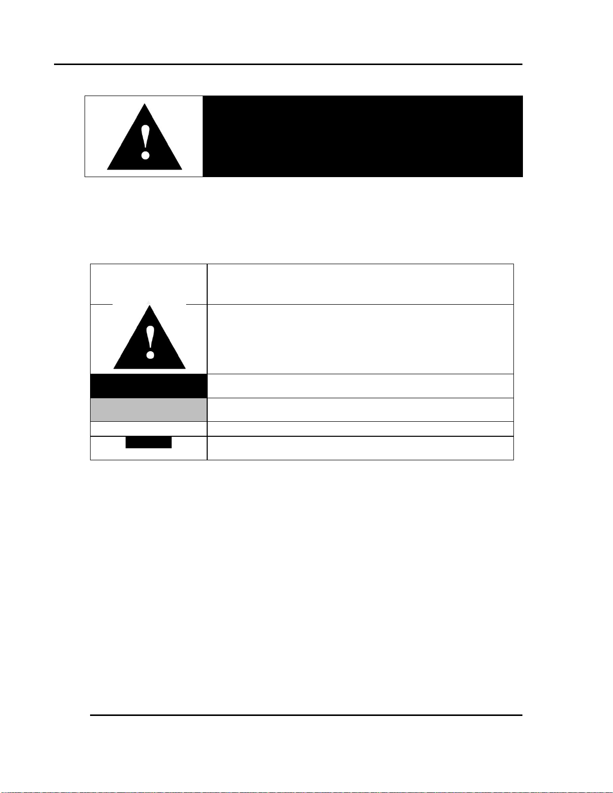
Danger!
Failure to heed warnings in this instruction manual and on the
oven could result in personal injury, property damage or death.
This icon signifies important information.
This icon signifies information that describes an unsafe condition
that may result in death, serious injury, or damage to the
equipment.
Danger!
A condition that may result in death, serious injury, or damage to
equipment.
Warning!
A condition that may result in serious injury or damage to
equipment.
Caution!
A condition that may result in damage to equipment or product.
LOG OUT
Reversed-out, Bold, 10pt Arial typeface indicates a specific key or
button on screen to click.
8 Version 26
1.4. Conventions
All rights reserved. No part of the contents of this manual may be reproduced, copied or transmitted in any form or by any
means including graphic, electronic, or mechanical methods or photocopying, recording, or information storage and
retrieval systems without the written permission of Despatch Industries, unless for purchaser's personal use.
Copyright © 2010 by Despatch Industries.
Page 9
Stackable LCC/LCD Oven Owner’s Manual ABOUT THIS MANUAL
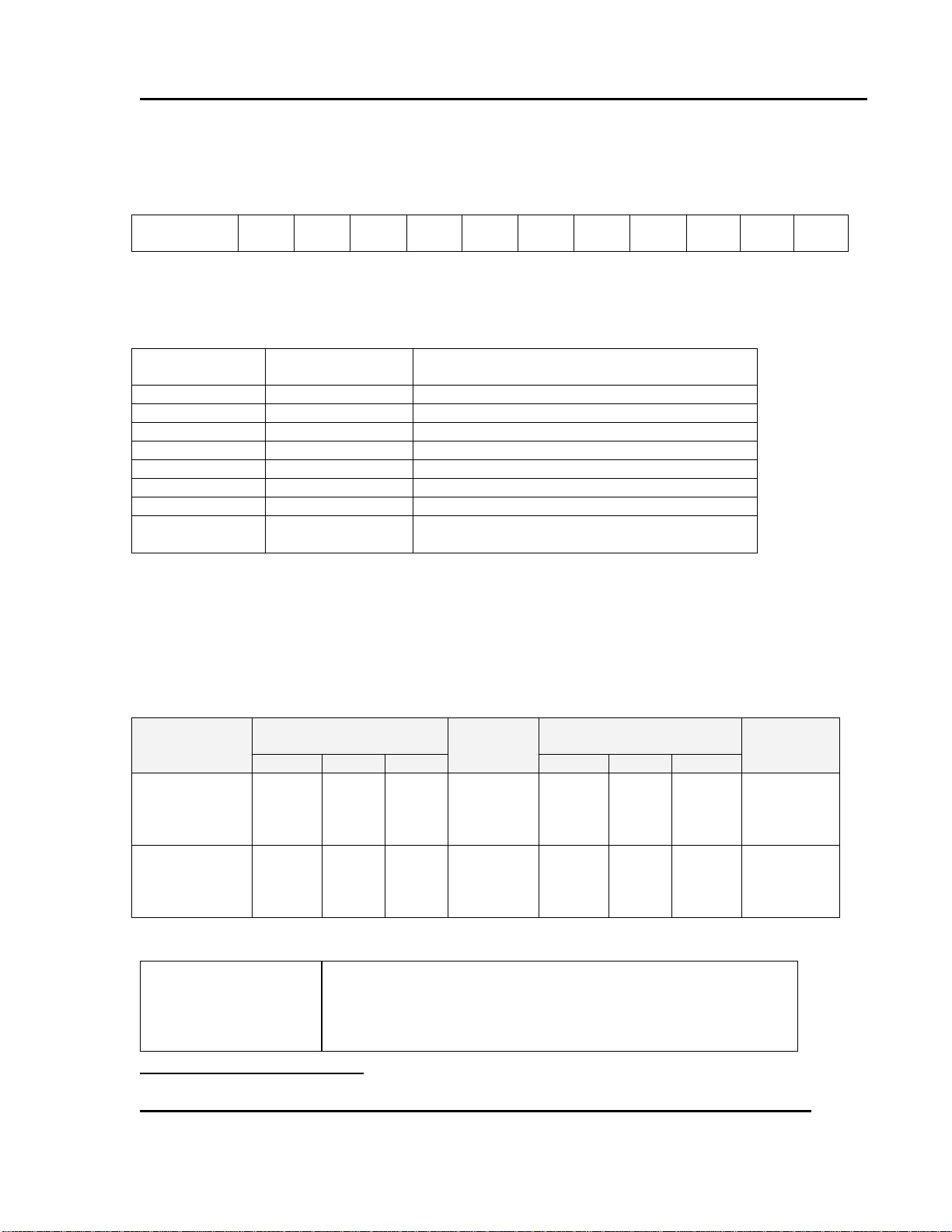
Model
Number
L 1 - - 3
Position in
Number
1 2 3 4 5 6 7 8
Position in
Model Number
Letter / Number
Letter Meaning
2
C
Model has a HEPA filter
2
L
Model does not have a HEPA filter
3
C
Model operates at 260°C
3
D
Model operates at 350°C
5 & 6
16
1.6 cubic foot model
5 & 6
51
5.1 cubic foot model
7 & 8
N
Model uses a nitrogen atmosphere
7 & 8
V
Model uses Viton* synthetic rubber (Siliconefree option)
Models
Chamber Size
inches (cm)
Capacity
ft3 (liters)
Overall Size
inches (cm)
Maximum
number of
Shelves
W D H W D
H
LCC1-16-3
LCD1-16-3
LCC1-16N-3
LCD1-16N-3
15
(38)
14
(36)
14
(36)
1.6
(45)
32.5
(83)
35.5
(90)
20.75
(53)
5
LCC1-51-3
LCD1-51-3
LCC1-51N-3
LCD1-51N-3
23
(58)
20
(51)
20
(51)
5.1
(144)
40.5
(103)
42.5
(108)
27
(69)
8
The LCC/LCD oven is not intended to process solvents or
other volatile or flammable materials. Oven exhaust is
intended for cooling purposes only.
Version 26 9
1.5. Specifications
1.5.1. Model Numbering and Naming Conventions
Table 1 lists the model numbers and follows these conventions:
Table 1. Model Number Key.
Example: LLD1-51NV-3
This 5.1 ft3 model does not have a HEPA filter, operates at 350°C, uses nitrogen
and is silicone-free.
1.5.2. Dimensions
*LLC & LLD models have same dimensions.
*
Trademark of E. I. Du Pont De Nemours & Company Corporation.
All rights reserved. No part of the contents of this manual may be reproduced, copied or transmitted in any form or by any
means including graphic, electronic, or mechanical methods or photocopying, recording, or information storage and
retrieval systems without the written permission of Despatch Industries, unless for purchaser's personal use.
Copyright © 2010 by Despatch Industries.
Page 10
ABOUT THIS MANUAL Stackable LCC/LCD Oven Owner’s Manual
Model
LCC1-16-3 & LCD1-16-3
LCC1-16N-3 & LCD1-16N-3
LCC1-51-3 & LCD1-51-3
LCC1-51N-3 & LCD1-51N-3
Maximum Load (Lbs)
200
200
Maximum shelf load (Lbs)
50
25
Recirculating fan
(CFM)
240
435
(H.P.)
1/4
1/4
Net weight (Approximate)
(Lbs)
250
380
(KG)
114
172
Shipping weight (Approximate)
(Lbs)
350
525
(KG)
159
238
Exhaust capacity (forced
exhaust) (CFM)
35
73
Exhaust Outlet
(Inch)
1.88 x 2.88
1.88 x 2.88
(mm)
(48.0 x 73.4)
(48.0 x 73.4)
Model
Volts *
Amps
Hertz
Heater Phase
KW
Cord and Plug
LCC1-16-3
LCD1-16-3
240
14.8
50/60
1
3
None, hardwired
LCC1-16N-3
LCD1-16N-3
240
14.0
50/60
1
3
None, hardwired
LCC1-51-3
LCD1-51-3
240
27.7
50/60
1
6
None, hardwired
LCC1-51N-3
LCD1-51N-3
240
27.7
50/60
1
6
None, hardwired
10 Version 26
1.5.3. Capacities
1.5.4. Power
If the line voltage for your LCC/LCD Oven varies more than 10% from the oven voltage
rating, electrical components such as relays and temperature controls may operate
erratically.
If the line voltage is lower than the oven voltage rating, heat-up time may be
significantly longer and motors may overload or run hot
If the line voltage is higher than the nameplate rating, motors may run hot and draw
excessive amperage
*The LCC/LCD Oven is designed for 240 volts (see oven nameplate) will operate
satisfactorily on a minimum of 208 Volts, but will result in 25% reduced heater output. If
your power characteristic is lower, contact Despatch Industries.
All rights reserved. No part of the contents of this manual may be reproduced, copied or transmitted in any form or by any
means including graphic, electronic, or mechanical methods or photocopying, recording, or information storage and
retrieval systems without the written permission of Despatch Industries, unless for purchaser's personal use.
Copyright © 2010 by Despatch Industries.
Page 11
Stackable LCC/LCD Oven Owner’s Manual ABOUT THIS MANUAL
Model
LCC1-16-3
LCD1-16-3
LCC1-16N-3
LCD1-16N-3
LCC1-51-3
LCD1-51-3
LCC1-51N-3
LCD1-51N-3
Time to
Temperature
(approximate
minutes)
(no load)
40°C –
100°C
7 min.
7 min.
5 min.
5 min.
40°C –
200°C
30 min.
30 min.
27 min.
27 min.
40°C –
260°C
45 min.
45 min.
35 min.
35 min.
40°C –
350°C†
60 min.
60 min.
50 min.
50 min.
Cooling Time to
Temp
Minutes
(No Load)‡
100°C –
55°C
35 min.
30§ min.
40 min.
25§ min.
200°C –
55°C
65 min.
55§ min.
75 min.
40§ min.
260°C –
55°C
75 min.
60§ min.
85 min.
45§ min.
350°C –
55°C†
130 min.
80§ min.
115 min.
50§ min.
Temperature
Uniformity at**
100°C
±1°C
±1°C
±1°C
±1°C
200°C
±2°C
±2°C
±2°C
±2°C
260°C
±3°C
±3°C
±3°C
±3°C
350°C
±4°C
±4°C
±4°C
±4°C
Maximum
Operating
Temperature
LCC
260°C
260°C
260°C
260°C
LCD
350°C
350°C
350°C
350°C
Operating
Range w/20°C
Ambient
LCC
40°C-260°C
35°C-260°C††
45°C- 260°C
35°C-260°C††
LCD
40°C-350°C
40°C-350°C††
40°C-350°C
40°C-350°C††
Control Stability
+/- 0.5°C
+/- 0.5°C
+/- 0.5°C
+/- 0.5°C
Version 26 11
1.5.5. Temperature
†
For LCD & LLD only, LCC & LLC maximum temperature: 260°C.
‡
Minimum operating temperatures and cooling times are based on a 20°C ambient temperature measured at
the fresh air inlet.
§
Based on cooling water supplied at 2 GPM (7.6 LPM), 16°C for nitrogen atmosphere units.
**
Uniformity figures are based on a nine-point test conducted in an empty oven with thermocouples
connected at 3 inches (7.6 cm) from walls after the oven temperature has reached stabilization. Uniformity
can vary slightly depending on unit and operating conditions. Class 100 HEPA filtration will limit ramp
rates.
††
Requires water cooling be activated for minimum temp rating and operation below 85°C.
All rights reserved. No part of the contents of this manual may be reproduced, copied or transmitted in any form or by any
means including graphic, electronic, or mechanical methods or photocopying, recording, or information storage and
retrieval systems without the written permission of Despatch Industries, unless for purchaser's personal use.
Copyright © 2010 by Despatch Industries.
Page 12

SAFETY Stackable LCC/LCD Oven Owner’s Manual
Danger!
Electrical panels contain high voltage. Disconnect and lock out
the power supply before working inside any electrical panels.
Failure to lock out the power supply can result in death or injury.
12 Version 26
2. Safety
2.1. Safety Information
Do not work on the Stackable LCC/LCD Oven without reading and understanding this
section which contains important information and warnings. Ignoring these warnings can
result in death, serious injury or damage to the machine and product.
2.1.1. Lockout
Machine lockout places the Stackable LCC/LCD Oven into a zero energy state and
prevents accidental machine start up. Always follow the Lockout Procedure described in
this Section before cleaning, maintaining or repairing the Stackable LCC/LCD Oven. An
accidental start-up, while working on the Stackable LCC/LCD Oven, can result in serious
injury or death.
2.1.1.1. Lockout Requirements
1. Every power source that can energize any element of the Stackable LCC/LCD Oven
must be shut off at the closest possible power source. This includes air, water and
electricity, including the Disconnect Switch.
2. After energy sources are locked out, test to ensure circuits are de-energized.
2.1.1.2. Lockout Procedure
Personnel authorized to lockout equipment must have the necessary locks to perform the
lockout.
1. Physically disconnect all electrical power to the machine or lockout the appropriate
breaker or disconnects.
2. Close all valves and bleed off any pressure.
3. Test for power by attempting a start with the machine controls.
4. Identify the Lockout Condition with a tag on the electrical disconnect and pneumatic
shut off valve.
5. When work is complete, remove all tags and restore the machine to its working state.
All rights reserved. No part of the contents of this manual may be reproduced, copied or transmitted in any form or by any
means including graphic, electronic, or mechanical methods or photocopying, recording, or information storage and
retrieval systems without the written permission of Despatch Industries, unless for purchaser's personal use.
Copyright © 2010 by Despatch Industries.
Page 13
Stackable LCC/LCD Oven Owner’s Manual SAFETY
Danger!
Contact with energized electrical sources may result in serious
injury or death.
Danger!
Electrical panels contain high voltage. Disconnect and lock out
the power supply before working inside any electrical panels.
Failure to lock out the power supply can result in death or injury.
Version 26 13
2.1.2. Door and Panel
The door and rear panel on the Stackable LCC/LCD Oven protect against hazards. Power
is required to open the door and the oven heater is OFF when the door is open. Operation
without these safety devices in place creates hazards that the doors and covers are
intended to render safe for personnel.
The door requires a Manual Override Key for use when power is off. The door and panel
that require a tool to open are part of the safety system of the Stackable LCC/LCD Oven.
Do not open the door while the machine is running.
2.2. Maintenance
Only qualified and trained personnel should perform maintenance or repair.
2.3. Electrical Power
Only qualified and trained personnel should perform electrical maintenance or electrical
repair.
Before performing maintenance, disconnect all electrical power from the machine.
Use a padlock and lockout all disconnects feeding power to the machine.
Never clean, or repair the oven when in operation.
Unauthorized alterations or modifications to Stackable LCC/LCD Oven are strictly
forbidden. Never modify any electrical circuits. Unauthorized modifications can
impair the function and safety of the Stackable LCC/LCD Oven.
All rights reserved. No part of the contents of this manual may be reproduced, copied or transmitted in any form or by any
means including graphic, electronic, or mechanical methods or photocopying, recording, or information storage and
retrieval systems without the written permission of Despatch Industries, unless for purchaser's personal use.
Copyright © 2010 by Despatch Industries.
Page 14

SAFETY Stackable LCC/LCD Oven Owner’s Manual
Danger!
Always disconnect all power before extinguishing a fire.
Attempting to extinguish a fire in a machine connected to
electrical power can result in serious injury or death!
14 Version 26
2.4. Fire
Keep the Stackable LCC/LCD Oven clean and free of scrap materials, oil or solvents to
prevent the possibility of fire. In the event of fire, use a fire extinguisher as follows.
1. De-energize the machine immediately by turning OFF the DISCONNECT SWITCH.
2. Turn off the remote main disconnect (customer supplied disconnect).
3. Extinguish the fire.
2.5. Equipment Lockout Requirements
To prevent injury or equipment damage during inspection or repair, the Stackable
LCC/LCD Oven must be locked out.
2.5.1. Emergency Stop
When a risk of personal injury or damage to the Stackable LCC/LCD Oven exists, turn
OFF the DISCONNECT SWITCH on the front of the oven. This shuts off all electrical
power to the oven.
All rights reserved. No part of the contents of this manual may be reproduced, copied or transmitted in any form or by any
means including graphic, electronic, or mechanical methods or photocopying, recording, or information storage and
retrieval systems without the written permission of Despatch Industries, unless for purchaser's personal use.
Copyright © 2010 by Despatch Industries.
Page 15
Stackable LCC/LCD Oven Owner’s Manual THEORY OF OPERATION
Danger!
Use care when working with nitrogen. Nitrogen presents an
asphyxiation hazard. Handle nitrogen according the safe
handling procedures listed in the material safety data sheet.
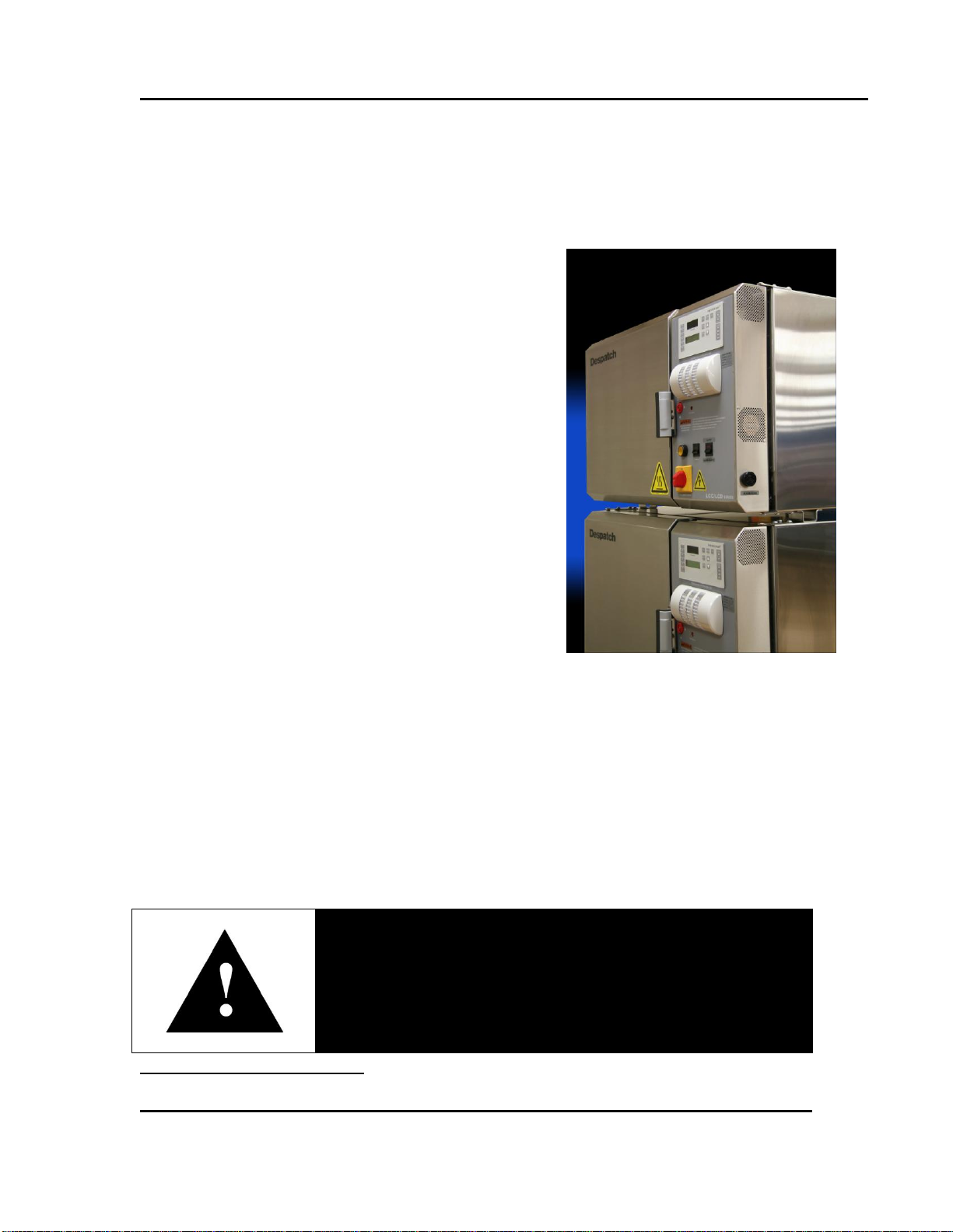
Figure 1. Stackable LCC/LCD Series Oven.
Version 26 15
3. Theory of Operation
3.1. The Stackable LCC/LCD Series Oven
The Stackable LCC/LCD Series Oven (Figure 1)
offers HEPA (High Efficiency Particulate Air)
filtration for processes where minimized
contamination is essential. The removable HEPA filter
is designed to provide a constant flow of 99.97% clean
air to the product being heated. The HEPA filter with
silicone seal provides 99.99% filtration.
The oven operator interface is located on the hinged
control panel at the front of the oven (Figure 1). Power
components are located on the equipment panel,
behind the hinged control panel, for easy access
(Figure 8). Electrical components are either touchproof or are shielded with Lexan7 material to prevent
accidental exposure during maintenance and
troubleshooting.
The cooling fan is controlled on/off by an event relay
in the Protocol Plus Control. The cooling fan is used
for rapid cool-down at the end of the process cycle, or
to maintain low temperature setpoints during process
cycle. It may also be turned on at the start of a process cycle to assure that starting
temperature is less than 70°C.
The nitrogen models have stainless steel water coil which permits rapid cool down and
lower temperature operation. The nitrogen oven comes with an adjustable flowmeter a for
adjusting purge rate, and needle valve for setting maintain rate, separate solenoid valves
for purge and maintain operation and a pressure relief exhaust port. An exhaust fan which
powers on whenever the oven is running maintains consistent chamber pressure control
with varied exhaust stack conditions.
7
Trademark of SABIC Innovative Plastics.
All rights reserved. No part of the contents of this manual may be reproduced, copied or transmitted in any form or by any
means including graphic, electronic, or mechanical methods or photocopying, recording, or information storage and
retrieval systems without the written permission of Despatch Industries, unless for purchaser's personal use.
Copyright © 2010 by Despatch Industries.
Page 16
THEORY OF OPERATION Stackable LCC/LCD Oven Owner’s Manual
Stackable units are available in air or nitrogen atmosphere models.
Nitrogen atmosphere models are noted with an N suffix. Model
numbers beginning with “LL*1-*” do not use a HEPA filter.
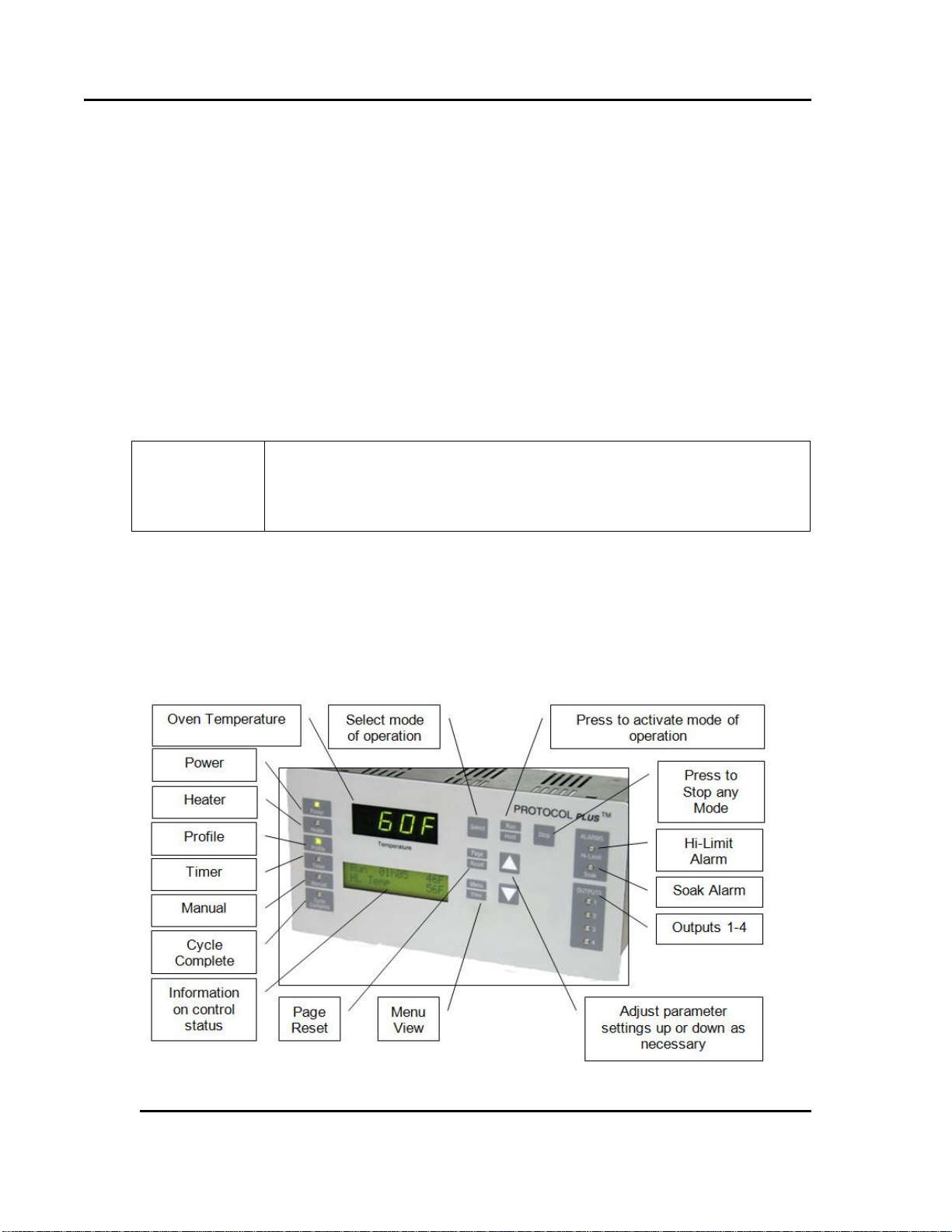
Figure 2. Protocol Plus Displays and Control Buttons.
16 Version 26
The oven has a type 304-2B stainless steel interior and a type 304-#4 stainless steel
interior. All interior seams are continuously welded on the insulation side. This protects
the work chamber from contaminated air and permits chamber washing without
damaging the insulation. Interior ductwork may be easily removed for cleaning. Heater
frame, fan wheel and motor shaft are constructed of stainless steel.
Two electropolished stainless steel wire shelves are provided. The shelves are removable
and adjustable on two inch centers.
The LCC/LCD series design offers a stackable oven body. Multiple oven systems of two
or three oven stack options are available. When operating multiple ovens, network the
Despatch Protocol Plus controllers together with a Modbus communication option. Use
the optional Despatch Protocol Manager software to enable customer PC control of
multiple ovens.
3.2. The Protocol Plus Controller
The Protocol Plus controller has two displays. A dedicated LED upper display shows the
oven temperature (Figure 2). A two line LCD lower display provides information on
control status, high limit temperature and allows changes to be made to the control
settings. Review the Protocol Plus controller Owner’s Manual for more information.
All rights reserved. No part of the contents of this manual may be reproduced, copied or transmitted in any form or by any
means including graphic, electronic, or mechanical methods or photocopying, recording, or information storage and
retrieval systems without the written permission of Despatch Industries, unless for purchaser's personal use.
Copyright © 2010 by Despatch Industries.
Page 17
Stackable LCC/LCD Oven Owner’s Manual THEORY OF OPERATION
LCC oven chamber temperature transitions must not exceed
1.5°C/minute to maintain class 100 chamber conditions. For ramp
rates greater than 1.5°C/minute and up to 5°C/minute, the LCD model
will maintain class 100 chamber conditions.
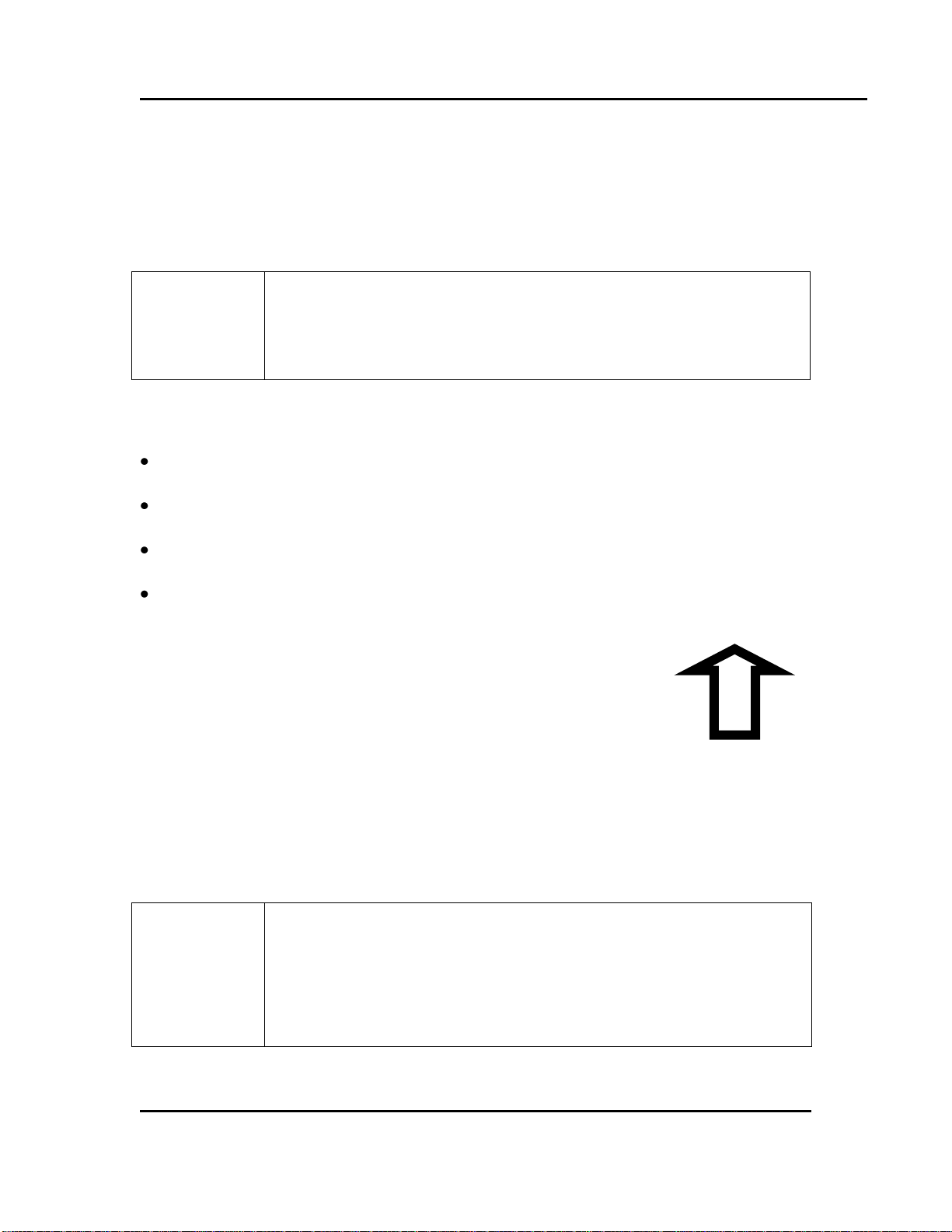
Ship, handle, store and install HEPA filters with pleats positioned
vertically. Horizontally-positioned pleats risk breaking at the adhesive
line of the filter medium. Horizontally-positioned pleats also collect
entrapped material on “shelves.” The accumulated weight of the
entrapped material may cause sag and lead to early failure of the filter
unit.
THIS SIDE UP
Figure 3. This Side Up Graphic.
Version 26 17
3.3. HEPA Filters
The Stackable LCC/LCD Ovens use HEPA (High Efficiency Particulate Air) filters limit
particulate size in the work chamber to 0.3 microns or less.
3.3.1. Definitions
Binder: Organic substance used in filter construction to provide the media with
structural strength
Burn-Off: Process for eliminating the binder and D.O.P. contained in the filter from
the manufacturing and testing function.
D.O.P.: Dioctyl Phthalate - Aerosol particles of submicron size used in testing phase
to spot defects or measure filter efficiency.
HEPA: High Efficiency Particulate Air
3.3.2. Filter Packaging, Shipping and Handling
Packaging practice varies among the filter unit
manufacturers. Filter units are typically packaged in
cardboard cartons with varying approaches for
strengthening the container and making it impact-resistant.
Shipping cartons are typically marked with a vertical arrow
and "This Side Up" (Figure 3). A filter unit is placed in the
carton so the pleated folds are vertical (running from top to
bottom), versus side to side.
All rights reserved. No part of the contents of this manual may be reproduced, copied or transmitted in any form or by any
means including graphic, electronic, or mechanical methods or photocopying, recording, or information storage and
retrieval systems without the written permission of Despatch Industries, unless for purchaser's personal use.
Copyright © 2010 by Despatch Industries.
Page 18
THEORY OF OPERATION Stackable LCC/LCD Oven Owner’s Manual
Caution!
Despatch does not recommend D.O.P. filter testing.
18 Version 26
The filter is typically shipped in the original carton or package provide by the filter
manufacturer. This carton or package provides good storage and maximum protection
from dirt and moisture. Store and move HEPA filters upright in the shipping carton.
Minimize handling of the filter. During installation, remove the filter from the shipping
carton and install directly into the oven.
If an unpackaged HEPA filter unit must be placed with its face on the floor or other
surface, clear the surface entirely of every object or irregularity which might damage the
filter pack.
3.3.3. HEPA Filter Validation Testing
Despatch Industries guarantees the HEPA filters will meet specified efficiency ratings
when the following recommendations are followed:
The filter is properly installed
The filter is run at or below 200°C, at a constant temperature
The filter is run before burn-in
3.3.3.1. D.O.P. Testing
D.O.P. testing uses aerosol particles of submicron size to spot defects or measure filter
efficiency. Degenerative by-products of this test are distributed throughout the oven
chamber upon heat-up. Despatch does not recommend D.O.P. filter testing.
3.3.3.2. Class 100 Testing
Despatch guarantees a Class 100 environment within the oven. This classification is
based on measurement of the particulate level within the oven work chamber.
Class 100 testing may be performed before or after a proper filter burn-in procedure has
been performed. Despatch guarantees Class 100 condition measurements based on two
methods of test. The direct method employs an extraction-type particulate analyzer. The
indirect method involves particle settling over a specified period of time onto a clean
disk.
All rights reserved. No part of the contents of this manual may be reproduced, copied or transmitted in any form or by any
means including graphic, electronic, or mechanical methods or photocopying, recording, or information storage and
retrieval systems without the written permission of Despatch Industries, unless for purchaser's personal use.
Copyright © 2010 by Despatch Industries.
Page 19

Stackable LCC/LCD Oven Owner’s Manual THEORY OF OPERATION
Version 26 19
3.3.3.3. Validation Testing
Despatch recommends the following test sequence for pharmaceutical Class 100 ovens.
1. Proper installation of the HEPA filters (Section 3.3.2).
2. Ambient air challenge to determine integrity of oven chamber and filter
gaskets.
3. Proper filter burn-off procedure.
4. Class 100 testing inside the work chamber.
3.3.3.4. HEPA Filter Burn-off Process Not Necessary
HEPA filters contain a binder material which protects the filter media during production
and shipping. Smoke produced from burning this binder at elevated temperatures is
undesirable during normal oven operation. Burning off the binder will ensure a clean
process at elevated temperatures.
However, when the binder is burned out of the filter media, the filter becomes
very fragile: too fragile to withstand normal shipping and handling. For this reason,
Despatch does not perform the burn-off procedure. The burn-off process is not necessary
at temperatures under 200°C.
3.3.4. HEPA Filter Unit Replacement
Periodic replacement the HEPA filter unit due to:
Resistance, or pressure drop, across the filter unit. Maximum level of resistance in
inches (water gauge) will vary depending upon the operation of the filter and the
available fan capacity. Adequate fan capacity must be available.
Loss of efficiency (leakage), determined from air-sampling measurements made
downstream of the filter unit.
Visible damage or rupture of the filter media in a unit.
Change in process application.
Excessive build-up of lint or combustible particulate matter on the filter unit.
Water droplets in airstream through filter, free water (RH = 100%), will saturate filter
very quickly and may cause burnout or holes in burned off filter media.
High level of radiation in the vicinity of the filter unit.
All rights reserved. No part of the contents of this manual may be reproduced, copied or transmitted in any form or by any
Copyright © 2010 by Despatch Industries.
means including graphic, electronic, or mechanical methods or photocopying, recording, or information storage and
retrieval systems without the written permission of Despatch Industries, unless for purchaser's personal use.
Page 20
THEORY OF OPERATION Stackable LCC/LCD Oven Owner’s Manual
A B C D E
F
Date
Comments
Pressure
(inches of
water)8
Pressure with:
150 SCFH (LCC1-
16); 200 SCFH
(LCC1-51) nitrogen
purge9
Pressure with:
75 SCFH (LCC1-
16); 150 SCFH
(LCC1-51) nitrogen
maintain9
Oven
Temperature
Typical
Values
2-3”
1.5-2” above value
in Column C
0.5-1” above value
in Column C
60°C
Filter first
installed
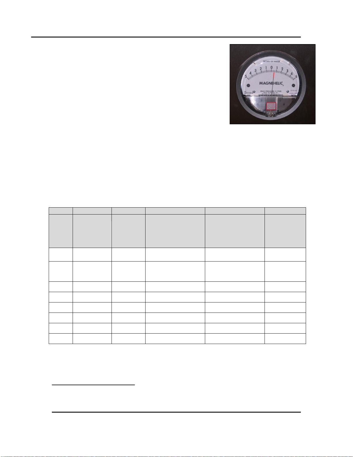
Figure 4. Magnehelic Pressure
Gauge Measures Pressure in front of
the HEPA filter.
20 Version 26
3.3.5. HEPA Filter: Magnehelic Pressure Gauge
The LCC Series oven is equipped with a Magnehelic
pressure gauge which measures the pressure in front of the
HEPA filter (Figure 4). As the filter becomes dirty, pressure
increases. Despatch recommends changing the filter when
the pressure is 1” w.c. greater than when the filter was first
installed (Refer to section 4.3 for filter replacement).
Since pressure can be affected by many factors involved in
the installation, it is important to record the pressure of a new
filter as a baseline. Recorded pressure readings allow for new
readings to be periodically checked against this baseline. Use
Table 2 for recording this information (See Section 8.1 for a
blank worksheet).
For a nitrogen atmosphere oven, pressure readings also give an indication of the integrity
of the seals. If the pressure recorded in Columns D or E decrease over time, inspect the
oven seals.
Table 2. HEPA Filter Pressure Reading Worksheet.
8
With Purge and Maintain valves off for a nitrogen atmosphere oven. Cooling fan off for an air
atmosphere oven.
9
For a nitrogen atmosphere oven only.
All rights reserved. No part of the contents of this manual may be reproduced, copied or transmitted in any form or by any
means including graphic, electronic, or mechanical methods or photocopying, recording, or information storage and
retrieval systems without the written permission of Despatch Industries, unless for purchaser's personal use.
Copyright © 2010 by Despatch Industries.
Page 21
Stackable LCC/LCD Oven Owner’s Manual ASSEMBLY & SETUP
Warning!
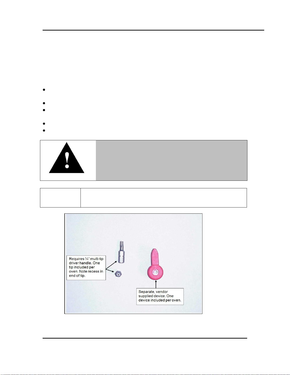
The LCC door requires a Manual Override Key for use when
power is OFF. The door and panel that require a tool to open are
part of the safety system of the Stackable LCC/LCD Oven. Do
not attempt to permanently mount the Manual Override Key.
Do not remove torx screw from door release mechanism. Manual
Override Key cannot be permanently mounted.
Figure 5. Door Lock Manual Override Key (LCC/LCD/LLC/LLD).
Version 26 21
4. Assembly & Setup
Assembly and Setup provides directions for unpacking and installing your LCC/LCD.
4.1. Unpack & Inspect The LCC/LCD Oven
Remove all packing materials and thoroughly inspect the oven for any damage that might
have occurred during shipment.
Note whether the carton and plastic cover sheet inside carton are still in good
condition
Observe all outside surfaces and corners of the oven for scratches and dents
Check oven controls and indicators for normal movement, bent shafts, cracks, chips
or missing parts such as knobs and lenses
Check the door and latch for smooth operation (Figure 5)
Check the filter carton for damage
Copyright © 2010 by Despatch Industries.
All rights reserved. No part of the contents of this manual may be reproduced, copied or transmitted in any form or by any
means including graphic, electronic, or mechanical methods or photocopying, recording, or information storage and
retrieval systems without the written permission of Despatch Industries, unless for purchaser's personal use.
Page 22

ASSEMBLY & SETUP Stackable LCC/LCD Oven Owner’s Manual
Warning!
Do not use the oven in wet, corrosive or explosive atmospheres
unless this oven is specifically designed for a special
atmosphere.
22 Version 26
4.1.1. If Damaged During Shipping
If damage occurred during shipping:
1. Contact the shipper immediately and file a written damage claim.
2. Contact Despatch Industries (1-800-473-7373 or 1-952-469-8230 or
service@despatch.com) to report your findings and to order replacement parts for
those damaged or missing. Send a copy of your filed damage claims to Despatch
industries (Despatch Industries, 8860 207th Street, Lakeville, MN 555044, USA).
3. Check the packing list to ensure you received all the specified components of the
oven system. If any items are missing, contact Despatch Industries to have missing
products forwarded to you.
4. Complete the warranty card and mail it to Despatch within 15 days after receipt of the
equipment.
4.2. Set-up The LCC/LCD Oven
4.2.1. Select Oven Location
4.2.1.1. Single Oven Placement Requirements
Bench top (or other framework) capable of holding at least 250 Lbs (113.4 Kgs).
A minimum of three (3) inches (7.6 cm) available in the rear of the oven for proper
ventilation.
Leave room at the oven sides and rear for maintenance.
Oven exhaust opening is at the rear of the left side of the oven. Allow at least two (2)
inches (5.1 cm) clearance here as well. The oven may be placed next to another
cabinet on its right, or next to another oven, with three-quarters of an inch (19 mm)
clearance (measure with door open).
Plumb and level the oven to assure proper heat distribution and operation of all
mechanical components.
4.2.1.2. Multiple Oven Placement Requirement
Stack up to three ovens vertically, with or without the optional framework (base)
supplied by Despatch.
All rights reserved. No part of the contents of this manual may be reproduced, copied or transmitted in any form or by any
means including graphic, electronic, or mechanical methods or photocopying, recording, or information storage and
retrieval systems without the written permission of Despatch Industries, unless for purchaser's personal use.
Copyright © 2010 by Despatch Industries.
Page 23

Stackable LCC/LCD Oven Owner’s Manual ASSEMBLY & SETUP
For the LCC1-51 oven model, only two ovens may be stacked
vertically.
Connection
(Figure 6)
LCC/LCD Air Atmosphere with
optional Water-Cooled Models
LCC/LCD Nitrogen Atmosphere
Models with standard water-cooling
NITROGEN
INLET
Clean Dry Air Inlet (70-80 psi
(4.83-5.52 bar))
Purge water from coil prior to
heating oven
¼” NPT female brass
connections provided
Nitrogen Inlet (70-80 psi (4.83-5.52
bar))
Purge nitrogen, clean dry air and
water from coil prior to heating the
oven
1/4” NPT female brass connections
provided.
WATER
OUTLET
During cooling cycle, water flows through the water coil and out this
connection
3/8” NPT female brass connections provided
Piping must be rated for up to 250 °F (121°C)
WATER
DRAIN
At the end of a cooling cycle, Nitrogen or Clean Dry Air is purged through
the water coil. Water and pressurized nitrogen/air exit this connection for 30
seconds. Must be connected to gravity style drain (no backpressure).
3/8” NPT female brass connections are provided.
Piping must be rated for up to 250 F (121 C)
WATER
INLET
Water Inlet for cooling
3/8” NPT female brass
connections provided
Requires 2 GPM flow at 61 °F
(16°C) to meet published cooling
rates.
Maximum Pressure 100 PSI
(6.89 Bar)
Water Inlet for cooling
3/8” NPT female brass connections
provided
Requires 3 GPM flow at 61 °F
(16°C) to meet published cooling
rates.
Maximum Pressure 100 PSI (6.89
Bar)
Version 26 23
Supporting surface must be capable of holding three ovens (750 Lbs or 340.2 Kg) or
the weight of two LCC1-51 oven models.
Use the holes in the rear oven feet to bolt the ovens together by removing the hole
plugs in the top of the mating oven beneath.
4.2.2. Oven Utility Connections
Utility connections vary slightly on different LCC/LCD models. Table 3 lists the
connection purposes and parameters. Refer to Figure 6 for visual reference.
Table 3. Oven Utility Connections.
All rights reserved. No part of the contents of this manual may be reproduced, copied or transmitted in any form or by any
means including graphic, electronic, or mechanical methods or photocopying, recording, or information storage and
retrieval systems without the written permission of Despatch Industries, unless for purchaser's personal use.
Copyright © 2010 by Despatch Industries.
Page 24

ASSEMBLY & SETUP Stackable LCC/LCD Oven Owner’s Manual
Nitrogen inlet
Water inlet
Flow-meter valve
Water outlet
Water drain
Water pressure supplied to the oven must not exceed 100 psi
(6.89 bar). Despatch recommends installing a regulator to
prevent surging.
Nitrogen pressure supplied should be greater the 70 psi (4.83
bar) but not more than 80 psi (5.52 bar).
Figure 6. LCC/LCD Connections Panel.
24 Version 26
4.2.2.1. Nitrogen With Water-Cooled Models
1. Connect nitrogen supply line to NITROGEN INLET at the connections panel (Figure 6).
2. Install water connection for cooling coils to WATER INLET (Figure 6). Verify the
valve on the flowmeter is turned OFF, that is, fully clockwise.
3. Check for leaks by slowly opening the valve on the flowmeter and allowing any air to
bleed out.
All rights reserved. No part of the contents of this manual may be reproduced, copied or transmitted in any form or by any
means including graphic, electronic, or mechanical methods or photocopying, recording, or information storage and
retrieval systems without the written permission of Despatch Industries, unless for purchaser's personal use.
Copyright © 2010 by Despatch Industries.
Page 25

Stackable LCC/LCD Oven Owner’s Manual ASSEMBLY & SETUP
Caution!
Failure to allow air to bleed from the flowmeter may damage the
flowmeter. Bleed air from the flowmeter after every instance of
shutting off the water supply.
WATER DRAIN must be left open-to-atmosphere. Make closedloop connections using WATER OUTLET (Figure 6).
Warning!
Never allow WATER DRAIN to be plugged. A hot oven generates
a small amount of steam when the water is first turned on.
Steam can burn skin.
Caution!
Design the drain system to prevent operator injury from high
temperature or pressure buildup. Piping must withstand short
periods of up to 500 °F (260°C) temperatures (662 °F (350°C) for
LCD ovens). Insulate drain lines or install warning labels stating
the potential high temperature or pressure hazard.
Clean Dry Air pressure supplied should be at 100 psi (6.9 bar).
Version 26 25
4. Adjust the flowmeter to the recommended 3 gpm (11.4 lpm).
5. Complete the drain connection on oven side by connecting WATER OUTLET to the
closed loop system (Figure 6).
4.2.2.2. Air Atmosphere with Optional Water Cooling Model
1. Connect Clean Dry Air (CDA) line to DRY AIR 100 PSI at the connections panel
(Figure 6).
2. Install water connection for cooling coils to WATER INLET (Figure 6). Verify the
valve on the flowmeter is turned OFF, that is, fully clockwise.
All rights reserved. No part of the contents of this manual may be reproduced, copied or transmitted in any form or by any
means including graphic, electronic, or mechanical methods or photocopying, recording, or information storage and
retrieval systems without the written permission of Despatch Industries, unless for purchaser's personal use.
Copyright © 2010 by Despatch Industries.
Page 26

ASSEMBLY & SETUP Stackable LCC/LCD Oven Owner’s Manual
Water pressure supplied to the oven must not exceed 100 psi
(6.9 bar). Despatch recommends installing a regulator to prevent
surging.
Caution!
Failure to allow air to bleed from the flowmeter may damage the
flowmeter. Bleed air from the flowmeter after every instance of
shutting off the water supply.
WATER DRAIN must be left open-to-atmosphere. Make closedloop connections using WATER OUTLET (Figure 6).
Warning!
Never allow WATER DRAIN to be plugged. A hot oven generates
a small amount of steam when the water is first turned on.
Steam can burn skin.
Caution!
Design the drain system to prevent operator injury from high
temperature or pressure buildup. Piping must withstand short
periods of up to 500 °F (260°C) temperatures (LCD ovens: 662 °F
(350°C). Insulate drain lines or install warning labels stating the
potential high temperature or pressure hazard.
26 Version 26
3. Check for leaks by slowly opening the valve on the flowmeter and allowing any air to
bleed out.
4. Adjust the flowmeter to the recommended 3 gpm (11.4 lpm).
5. Complete the drain connection on oven side by connecting WATER OUTLET to the
closed loop system (Figure 6).
All rights reserved. No part of the contents of this manual may be reproduced, copied or transmitted in any form or by any
means including graphic, electronic, or mechanical methods or photocopying, recording, or information storage and
retrieval systems without the written permission of Despatch Industries, unless for purchaser's personal use.
Copyright © 2010 by Despatch Industries.
Page 27

Stackable LCC/LCD Oven Owner’s Manual ASSEMBLY & SETUP
LCC/LCD1-16 Models
LCC/LCD1-51Models
Size
1.88” x 2.88” (4.8 cm x 7.3 cm)
Flow
35 cfm (991.5 lpm)
73 CFM (2067 lpm)
Temperature
LCC and LLC series:
500 °F (260°C)
LCC and LLC series:
500 °F (260°C)
LCD and LLD series:
662 °F (350°C)
LCD and LLD series:
662 °F (350°C)
The oven must be hardwired directly to the disconnect switch on
the equipment panel (Figure 9).
Danger!
All grounding and safety equipment must be in compliance with
applicable codes, ordinances and accepted safe practices.
Figure 7. Exhaust Port on the Left Side of the LCC/LCD Oven.
Version 26 27
4.2.3. Exhaust Connections
The LCC/LCD Exhaust port is located on the left side of the oven (Figure 7). Table 4 lists
the requirements for the exhaust stack for the LCC/LCD Oven.
Table 4. Exhaust Connection Requirements.
4.2.4. Wiring & Power Connections
All rights reserved. No part of the contents of this manual may be reproduced, copied or transmitted in any form or by any
means including graphic, electronic, or mechanical methods or photocopying, recording, or information storage and
retrieval systems without the written permission of Despatch Industries, unless for purchaser's personal use.
Copyright © 2010 by Despatch Industries.
Page 28

ASSEMBLY & SETUP Stackable LCC/LCD Oven Owner’s Manual
Figure 8. Open the front panel for access.
28 Version 26
Run line voltage power through the conduit from rear of oven to front (Figure 9).
Consult electrical drawings included with the oven for details.
Access the conduit and Disconnect Switch by opening the front panel (Figure 8).
All rights reserved. No part of the contents of this manual may be reproduced, copied or transmitted in any form or by any
means including graphic, electronic, or mechanical methods or photocopying, recording, or information storage and
retrieval systems without the written permission of Despatch Industries, unless for purchaser's personal use.
Copyright © 2010 by Despatch Industries.
Page 29

Stackable LCC/LCD Oven Owner’s Manual ASSEMBLY & SETUP
Not all ovens use a HEPA filter. This section applies only to
ovens are equipped with a HEPA filter. Model numbers
beginning with “LC” have a HEPA filter. For a complete
explanation of model numbers, refer to Section 1.5.1.
Warning!
Make certain power is disconnected from the oven before
removing or replacing the HEPA filter. Observe all applicable
safety procedures.
Caution!
The HEPA filter is fragile and care must be taken to avoid
damage during installation. If a filter unit is dropped, whether in
the carton or not, examine it carefully for damage.
Conduit on rear of oven
Connect line voltage
power to Disconnect
Switch labeled LINE
CONNECTION.
Line voltage power
emerges from conduit on
front of oven here.
Route line voltage power
through conduit
Figure 9. Conduit entrance at rear of oven and open front panel.
Version 26 29
Connect the line voltage power to the disconnect switch labeled LINE CONNECTION
(Figure 9).
4.3. HEPA Filter Installation
All rights reserved. No part of the contents of this manual may be reproduced, copied or transmitted in any form or by any
means including graphic, electronic, or mechanical methods or photocopying, recording, or information storage and
retrieval systems without the written permission of Despatch Industries, unless for purchaser's personal use.
Copyright © 2010 by Despatch Industries.
Page 30

ASSEMBLY & SETUP Stackable LCC/LCD Oven Owner’s Manual
Caution!
The HEPA filter must be installed so that unfiltered air cannot
leak past the unit. The HEPA gasket (white triangular gasket) is
generally in the downstream position and in contact with the
oven-sealing surface
In general, defer to installation instructions provided by the filter
manufacturer.
Termikfil 2000 Filter Installation Notes:
If a spacer is required for the gasket, place the spacer on the
opposite side to the HEPA gasket
If the Termikfil 2000 filter is mounted in a slide, do not rub
the filter on its gaskets
Any clamping device used must allow necessary and
sufficient pressure on the gaskets provide an airtight fit.
NOTE: Over tightening may damage the Termikfil 2000 filter.
Clamping recommendation: Clamp the Termikfil 2000 filter to
a residual HEPA gasket thickness of 4 mm (1/6 inch)
Refer to installation instructions provided by the filter
manufacturer for more specific installation notes.
Sweep floor clear of nuts, bolts and other protrusions which
may damage the unit.
Do not drop or jar the filter carton.
30 Version 26
1. Remove filter from carton
a. Place carton on floor.
b. Tilt the carton on one corner. Handle the carton at opposing corners.
c. Remove sealing tape and fold back flaps of carton.
d. Gently upend the filter to place the exposed end of the filter on the floor. Do
All rights reserved. No part of the contents of this manual may be reproduced, copied or transmitted in any form or by any
means including graphic, electronic, or mechanical methods or photocopying, recording, or information storage and
retrieval systems without the written permission of Despatch Industries, unless for purchaser's personal use.
not jar the filter.
e. Pull the carton from the filter unit. Be careful to not pull the filter from the
carton.
Copyright © 2010 by Despatch Industries.
Page 31

Stackable LCC/LCD Oven Owner’s Manual ASSEMBLY & SETUP
Opened pleats in the filter media are normal and result from the
tempering process.
Figure 10. Example HEPA Filter (Silicone-free) and Close-Up.
Version 26 31
2. Inspect the filter.
a. Visually inspect the two gaskets to ensure they have not been damaged during
handling.
b. Use a strong lamp to examine the exposed areas of both faces for evidence of
breaks, cracks, or pinholes (Figure 10). If a strong lamp is unavailable, use a
flashlight in a darkened room.
c. Look for visible defects with the light projected along the full length of each
channel created by the separators. Translucent spots may not necessarily
indicate holes or cracks but may simply be variations in thickness of the filter
medium.
d. Check that the adhesive seal around the filter unit faces are complete and
unbroken.
e. Check frame corner joints for adhesive sealing and tightness.
f. Check that gaskets are cemented firmly to the filter frame and that gasket
pieces are undamaged and butted or mated at the joints.
3. Pull shelves from the oven and set aside (Figure 11).
All rights reserved. No part of the contents of this manual may be reproduced, copied or transmitted in any form or by any
means including graphic, electronic, or mechanical methods or photocopying, recording, or information storage and
retrieval systems without the written permission of Despatch Industries, unless for purchaser's personal use.
Copyright © 2010 by Despatch Industries.
Page 32

ASSEMBLY & SETUP Stackable LCC/LCD Oven Owner’s Manual
Danger!
Make certain power is disconnected from the oven before
removing or replacing the HEPA filter.
Remove shelves before installing HEPA FILTERS
Loosen threes screws to remove the entire inner
casing assembly as a single unit.
Loosen ¼ turn using
5/16 inch nut driver.
Figure 11. Remove inner casing to install HEPA filter.
32 Version 26
4. Loosen the two screws at the upper and lower corners of the right rear of the chamber
(Figure 11).
a. Pull out the shelf support/duct as a single unit and set it aside.
5. Note the position of the threaded rods behind the duct assembly on the right side. The
HEPA filter will be fitted over these rods.
6. Remove the brass nuts and washers from the rods that are temporarily locking the
rods to the oven wall.
a. Reuse these nuts to hold the filter in place.
7. This step for the LCC1-16-3 only:
a. Remove filter frame to be reinstalled after filter.
b. Remove the HEPA filter (shipped separately) from its container.
c. NOTE: The seal side goes toward the wall of the oven.
i. Place the filter inside the chamber and install filter mounting frame
over rods.
ii. Push filter tight to rear wall with mounting frame.
All rights reserved. No part of the contents of this manual may be reproduced, copied or transmitted in any form or by any
means including graphic, electronic, or mechanical methods or photocopying, recording, or information storage and
retrieval systems without the written permission of Despatch Industries, unless for purchaser's personal use.
Copyright © 2010 by Despatch Industries.
Page 33

Stackable LCC/LCD Oven Owner’s Manual ASSEMBLY & SETUP
While the Termikfil 2000 filter has undergone tempering
treatment at the factory, smells and/or fumes may be released
during the first use at temperature.
Version 26 33
8. This step for the LCC1-51-3 only:
a. Remove the HEPA filter (shipped separately) from its container.
b. NOTE: The seal side goes toward the wall of the oven.
i. Place the filter inside the chamber and install filter mounting angles
(shipped separately) over rods.
ii. Push filter tight to rear wall with mounting angles.
9. Reinstall the washers and brass nuts to tighten the filter frame down.
a. Tighten the four nuts alternately for even tightness (Correct installation torque
is 28 +/- 3 in-lbs. Be careful not to over tighten.
b. Correct installation torque is 28 +/- 3 in-lbs.
c. Be sure to compress the gasket evenly and equally at all points with the filter
frame completely covering the opening.
10. Reinstall the inner casing assembly using the three screws removed earlier (Step 4).
11. Reinstall the oven shelf.
4.3.1. HEPA Filter Burn-Off
4.3.1.1. HEPA Filter Burn-Off Process
The burn-off process takes place in any equipment where a new HEPA filter is used at
temperatures above 180°C / 356°F. Expect smoke, possibly a pungent odor and a light
residue on interior surfaces. This results from oxidation of the binder. Most of the binder
will leave the filter after running at a temperature of 260°C/500°F for 48 hours. Check
the oven for particles or the exhaust for smoke and odor to determine that the process is
finished.
4.3.1.2. Location of HEPA Filter Burn-Off Process
Select a location for the burn-off process where generated smoke and odor will be
ventilated with the least amount of interruption and inconvenience. Ideally this will be in
the final location for the oven. However, it may be a receiving dock, some well ventilated
space or even outside if the weather is acceptable. If this location is a very clean area, pay
special attention to an exhaust hook-up that fully captures the smoke and odor produced.
The post-Burn-off cleaning (that is, oven wipe down) may also generate dust. So take
care if in a clean room.
All rights reserved. No part of the contents of this manual may be reproduced, copied or transmitted in any form or by any
means including graphic, electronic, or mechanical methods or photocopying, recording, or information storage and
retrieval systems without the written permission of Despatch Industries, unless for purchaser's personal use.
Copyright © 2010 by Despatch Industries.
Page 34

ASSEMBLY & SETUP Stackable LCC/LCD Oven Owner’s Manual
LCC oven chamber temperature transitions must not exceed
1.5°C/minute to maintain class 100 chamber conditions. For ramp
rates greater than 1.5°C/minute and up to 5°C/minute, the LCD model
will maintain class 100 chamber conditions.
24 hours
24 hours
Process
Temperature
Option 1
Option 2
48 hours
48 hours
Temperature Ramp 1.7°C/min up
to 5°C/Min
Temperature
Ramp 1.7°C/
min
Figure 12. Options for Starting Termikfil 2000 Filter.
34 Version 26
4.3.1.3. Recommended HEPA Filter Burn-Off Process
1. Locate the equipment exhaust opening where chamber air is being expelled.
a. If the oven filter is burned off in a clean area, be sure to handle the equipment
exhaust appropriately.
b. If the equipment is large and the exhaust stack is a permanent service connection,
connect the equipment and exhaust stack before the burn-off process.
c. If the equipment is small with no permanent exhaust duct required, arrange a
temporary connection out of the clean area that will handle the maximum
temperature of the equipment. Direct the smoke and odor outside, or to a highly
ventilated area.
2. Set the temperature control at the maximum process temperature.
a. Silicone: Ramp at 1.25°C/min to 260°C and soak for 48 hours.
b. Media Pack: Ramp at 1.25°C/min to 260°C and soak for 48 hours.
c. Termikfil (Figure 12):
i. Option 1: Ramp at 1.7°C/min (or up to 5°C/min) to 350°C and soak for 48
hours.
ii. Option 2: Ramp to process temperature and soak for three consecutive three-
hour segments over 48 hours.
All rights reserved. No part of the contents of this manual may be reproduced, copied or transmitted in any form or by any
means including graphic, electronic, or mechanical methods or photocopying, recording, or information storage and
retrieval systems without the written permission of Despatch Industries, unless for purchaser's personal use.
Copyright © 2010 by Despatch Industries.
Page 35

Stackable LCC/LCD Oven Owner’s Manual ASSEMBLY & SETUP
If the equipment must be moved after the burn-off process, use
considerable care.
The binder which strengthened new filters is now burned-off
and the media is very fragile.
Rough handling of either the filter alone or the equipment
with the filter installed is not recommended as it may tear the
media and lead to reduced filter efficiency.
Removal of the filter after heating can also result in damage
to the frame seal, and is only recommended when replacing
the filter.
Refer to instructions provided recorder manufacturer for more
specific installation notes.
Version 26 35
3. Start the fan after making the electrical power connections.
4. Energize the equipment heater.
a. Use enough fresh air (or N2) to remove the smoke, while still being able to
achieve and maintain the necessary temperature.
b. The completion of the burn-off period should be based on the particle level in the
oven or smoke-free exhaust and minimal odor level.
c. Check the filter hold-down nuts after burn-off and tightened as necessary.
d. For best oven particle control, this step should be repeated on a regular basis.
4.4. MRC5000 Setup (Optional)
Temperature is retransmitted to the MRC5000 recorder from the controller. Set up the
recorder by:
1. Ensure hardware jumper JU1 is in place for the 5 VDC setting (Refer to MRC5000
Manual included).
2. Move Mode to PROG/TEST/CAL to display Prog.
3. Press ▼ twice to display Inps. Move to each Parameter Code using ▼or ▲. Adjust
each Parameter Code using the settings in Table 5.
4. After adjusting all settings, move Mode to RUN. Display on both the Recorder and
controller should read the same.
Copyright © 2010 by Despatch Industries.
All rights reserved. No part of the contents of this manual may be reproduced, copied or transmitted in any form or by any
means including graphic, electronic, or mechanical methods or photocopying, recording, or information storage and
retrieval systems without the written permission of Despatch Industries, unless for purchaser's personal use.
Page 36

ASSEMBLY & SETUP Stackable LCC/LCD Oven Owner’s Manual
Parameter Code
Degrees C
Degrees F
Inps
18
18
Icor 0 0
diSP
On
On
dPOS
0
0
EUU**
400
752
EUL**
0
32
ChUP
400
800*
ChLO
0 0 DFF
1
1
36 Version 26
Table 5. MRC 5000 Settings.
* Change 0-400 chart paper to 0-800 chart paper. Depending on the equipment used, 0-
600 paper may be used if the maximum temperature is 500 degrees F.
** These values must match the settings sRetOutLo and RetOutHi on the Protocol Plus
Control page. For example, if RetOutLo is 32, EUL must read 32.
Copyright © 2010 by Despatch Industries.
All rights reserved. No part of the contents of this manual may be reproduced, copied or transmitted in any form or by any
means including graphic, electronic, or mechanical methods or photocopying, recording, or information storage and
retrieval systems without the written permission of Despatch Industries, unless for purchaser's personal use.
Page 37

Stackable LCC/LCD Oven Owner’s Manual OPERATION
Users and operators of this oven must comply with operating
procedures and training of operating personnel as required by
the Occupational Safety and Health Act (OSHA) of 1970, Section
5 and relevant safety standards, and other safety rules and
regulations of state and local governments. Refer to the relevant
safety standards in OSHA and National Fire Protection
Association (NFPA), Section 86 of 1990.
Despatch Industries cannot be responsible for either the
process or process temperature used, or for the quality of the
product being processed. It is the responsibility of the
purchaser and operator to see that the product undergoing
processing in a Despatch oven is adequately protected from
damage.
Carefully following the instructions in this manual will help the
purchaser and operator in fulfilling that responsibility.
Caution!
Always place loads on the shelves provided to avoid possible
uneven heating and damage to the oven.
Version 26 37
5. Operation
5.1. Load Oven
Avoid spilling on the heater elements or oven floor when loading the oven. Do not place
the load on the oven floor plate. Placing the load on the oven floor may cause the load to
heat unevenly and the weight may cause shorting out of the heater elements. Use the
shelves provided.
The two shelves are designed to be pulled out about halfway without tipping. Do not
overload the shelves. Distribute the workload evenly so airflow is not restricted. Do not
overfill your oven. The workload should not take up more than two-thirds of any
dimension of the inside cavity.
Copyright © 2010 by Despatch Industries.
All rights reserved. No part of the contents of this manual may be reproduced, copied or transmitted in any form or by any
means including graphic, electronic, or mechanical methods or photocopying, recording, or information storage and
retrieval systems without the written permission of Despatch Industries, unless for purchaser's personal use.
Page 38

OPERATION Stackable LCC/LCD Oven Owner’s Manual
Warning!
Do not use flammable solvent or other flammable material in this
oven. Do not process closed containers of any substance or
liquid in this oven because they may explode under heat.
38 Version 26
5.2. Pre-Startup Checklist
□ Know the system. Read this manual carefully. Make use of its instructions and
explanations. Safe, continuous, satisfactory, trouble-free operation depends primarily
on your degree of understanding the system and your willingness to keep all parts in
proper operating condition.
□ Check line voltage. Voltage must correspond to nameplate requirements of motors
and controls. A wrong voltage can result in serious damage. Refer to Section 1.5.4 for
more information.
□ Check fresh air and exhaust openings. Do not be careless about restrictions in and
around the fresh air and exhaust openings and stacks. Under no condition can they be
permitted to become so filled with dirt that they reduce airflow.
All rights reserved. No part of the contents of this manual may be reproduced, copied or transmitted in any form or by any
means including graphic, electronic, or mechanical methods or photocopying, recording, or information storage and
retrieval systems without the written permission of Despatch Industries, unless for purchaser's personal use.
Copyright © 2010 by Despatch Industries.
Page 39

Stackable LCC/LCD Oven Owner’s Manual OPERATION
DISCONNECT
SWITCH
POWER Switch
DOOR RELEASE
During the process cycle, DOOR
RELEASE will not be lit, meaning
that the oven door may not be
opened.
Figure 13. Power the Oven.
Version 26 39
5.3. Operating Procedure
5.3.1. Start Oven
1. Turn the yellow/red
DISCONNECT SWITCH to ON.
2. Press the POWER to ON.
a. The DOOR RELEASE
pushbutton will
illuminate. This means
the door can be opened.
b. For Optional Beacon Light-equipped Units Only: The amber (center)
beacon light will illuminate, indicating that the oven is ready to receive work
to be processed.
3. To open the oven door, press DOOR RELEASE while simultaneously pressing on the
door. The oven door will unlatch and open.
4. The heater is wired in series with the door switch. The door must be completely
closed and locked to activate the heater.
5.3.2. Working with Protocol Plus Operating Modes
Refer to the Protocol Plus Controller Owner’s Manual for specific information for
working with the controller.
5.3.3. Sequence of Operation for Ovens Equipped with Optional Beacon
Light
1. After starting the oven (refer to Section 5.3.1), the Protocol Plus controller initializes.
a. The oven should be idle, empty, with the door closed and awaiting the next lot
for processing.
b. The Protocol Plus Controller should not be running a profile.
2. Open the oven door.
All rights reserved. No part of the contents of this manual may be reproduced, copied or transmitted in any form or by any
means including graphic, electronic, or mechanical methods or photocopying, recording, or information storage and
retrieval systems without the written permission of Despatch Industries, unless for purchaser's personal use.
Copyright © 2010 by Despatch Industries.
Page 40

OPERATION Stackable LCC/LCD Oven Owner’s Manual
The amber beacon light will be ON (steady) until the profile is
started (at the completion of Step 5).
Press Run at any time to active the Profile Mode.
After pressing Run, the display changes from Stop to Run.
Segment time remaining and Current Segment number will
display.
40 Version 26
3. Place the product on the shelf in the oven.
4. Close the oven door.
5. Run the desired profile with the Protocol Plus Controller.
a. Press Select until Profile is displayed.
b. Press ▲ or ▼ to display the desired profile.
c. Press Run to start the Profile Mode.
6. At this point, the oven profile cycle is in process and the door is locked.
a. The green beacon light is ON (steady), the amber beacon light is off.
b. When the process is complete, the amber beacon should be ON, and the DOOR
RELEASE pushbutton light is on.
7. Press DOOR RELEASE pushbutton
8. Open the oven door to remove the product workload.
9. Closes the oven door to complete the process cycle. The oven is ready for the next lot.
All rights reserved. No part of the contents of this manual may be reproduced, copied or transmitted in any form or by any
means including graphic, electronic, or mechanical methods or photocopying, recording, or information storage and
retrieval systems without the written permission of Despatch Industries, unless for purchaser's personal use.
Copyright © 2010 by Despatch Industries.
Page 41

Stackable LCC/LCD Oven Owner’s Manual OPERATION
Figure 14. Nitrogen Flowmeter.
Refer to the Protocal Plus™ Controller Owner’s Manual for more
information on programming event outputs.
Press Run at any time to
activate the Profile Mode.
Oven Model
Mode
< 100 PPM
<1000 PPM
LCC1-16
Purge
150 scfh
125 scfh
Maintain
75 scfh
65 scfh
LCC1-51
Purge
200 scfh
175 scfh
Maintain
160 scfh
140 scfh
Version 26 41
5.3.4. Sequence of Operation for Ovens Equipped for Inert Atmosphere
Oven
1. After starting the oven (Section 5.3.1), the Protocol Plus controller initializes.
a. The oven should be idle, empty, with the door closed
and awaiting the next lot for processing.
b. The Protocol Plus Controller should not be running a
profile.
c. Make certain the nitrogen flow meter is in the OFF
position, that is, fully clockwise (Figure 14).
2. Open the oven door.
3. Place the product on the shelf in the oven.
4. Close the oven door.
5. Run the desired profile with the Protocol Plus Controller.
a. Press Select until Profile is displayed.
b. Press ▲ or ▼ to display the desired profile.
c. Press Run to start the Profile Mode.
6. The first segment of the program is the PURGE MODE.
a. Set the nitrogen flow meter (Figure 14) to the desired setting (Table 6).
b. This program energizes the purge solenoid valve.
Table 6. Desired Oxygen Concentration.
7. The second segment is the MAINTAIN MODE:
a. The purge solenoid valve is first de-energized and then re-energized to maintain
the nitrogen level to less than the purge level.
b. Adjust the Nitrogen Maintain needle valve at rear of oven (Figure 15). Leave the
maintain valve energized as long as the nitrogen level is maintained (Table 6).
All rights reserved. No part of the contents of this manual may be reproduced, copied or transmitted in any form or by any
means including graphic, electronic, or mechanical methods or photocopying, recording, or information storage and
retrieval systems without the written permission of Despatch Industries, unless for purchaser's personal use.
Copyright © 2010 by Despatch Industries.
Page 42

OPERATION Stackable LCC/LCD Oven Owner’s Manual
Figure 16. Water and Nitrogen Piping Schematic.
Figure 15. Adjust Nitrogen Maintain Needle
Valve.
42 Version 26
8. The third and final segment is the COOLDOWN MODE. In Cooldown mode, water
valves are energized to bring the chamber to a safe unloading temperature (Figure
16).
All rights reserved. No part of the contents of this manual may be reproduced, copied or transmitted in any form or by any
means including graphic, electronic, or mechanical methods or photocopying, recording, or information storage and
retrieval systems without the written permission of Despatch Industries, unless for purchaser's personal use.
Copyright © 2010 by Despatch Industries.
Page 43

Stackable LCC/LCD Oven Owner’s Manual OPERATION
Version 26 43
5.3.5. Manual Unlock and Main Disconnect
5.3.5.1. Manual Unlock
If a power failure occurs insert a torx tip tool (provided) and rotate 90 degrees
counterclockwise to allow the chamber door to open. The tool must be turned back to the
locked position to allow electrical operation again.
5.3.5.2. Main Disconnect Switch
This disconnect switch (yellow with red knob) is connected to the load break switch
behind the panel that disconnects or connects power from the main line.
All rights reserved. No part of the contents of this manual may be reproduced, copied or transmitted in any form or by any
Copyright © 2010 by Despatch Industries.
means including graphic, electronic, or mechanical methods or photocopying, recording, or information storage and
retrieval systems without the written permission of Despatch Industries, unless for purchaser's personal use.
Page 44

MAINTENANCE Stackable LCC/LCD Oven Owner’s Manual
44 Version 26
6. Maintenance
Do not attempt any service on this oven before opening the main power disconnect
switch.
6.1. Checklist
Keep equipment clean. Gradual dirt accumulation retards airflow. A dirty oven can
result in unsatisfactory operation such as unbalanced temperature in the work
chamber, reduced heating capacity, reduced production, overheated components, and
the like. Keep the walls, floor and ceiling of the oven work chamber free of dirt and
dust. Floating dust or accumulated dirt may produce unsatisfactory work results.
Keep all equipment accessible. Do not permit other materials to be stored or piled
against it.
Protect controls against excessive heat—particularly controls, motors or other
equipment containing electronic components. Temperatures greater than 51.5°C
(125°F) should be avoided.
Establish maintenance and checkup schedules. Do this promptly and follow the
schedules faithfully. Careful operation and maintenance will be more than paid for in
continuous, safe and economical operation.
Maintain equipment in good repair. Make repairs immediately. Delays may be costly
in added expense for labor and materials and in prolonged shut down.
Practice safety. Make it a prime policy to know what you are doing before you do it.
Make caution, patience, and good judgment the safety watchwords for the operation
of your oven.
Inspect oven seals if pressure readings decrease over time (Refer to Section 3.3.5 as
well as Table 2, Columns D and/or E)
6.2. Lubrication
Fan motor bearings are permanently lubricated. All door latches, hinges, door operating
mechanisms, bearing or wear surfaces should be lubricated to ensure easy operation.
6.3. HEPA Filter Replacement
Refer to section 4.3 for filter replacement.
Copyright © 2010 by Despatch Industries.
All rights reserved. No part of the contents of this manual may be reproduced, copied or transmitted in any form or by any
means including graphic, electronic, or mechanical methods or photocopying, recording, or information storage and
retrieval systems without the written permission of Despatch Industries, unless for purchaser's personal use.
Page 45

Stackable LCC/LCD Oven Owner’s Manual TROUBLESHOOTING
Alarm Status
Possible Problem
Next Step
Hi-Limit LED flashing
Problem with thermocouple
Hi-limit setpoint has been
exceeded.
Once the problem has corrected,
press Reset.
Soak LED flashing
Oven temperature has not
entered (or dropped out of) the
soak band and the soak timer
has stopped
Program a slower ramp rate or if
oven is not heating check heater
circuit.
Top LED displays
OPEN and lower LCD
displays CONTROL
SENS ERR
Control thermocouple is
disconnected or broken
Repair or replace the thermocouple.
Lower LCD displays HI
LIM SENS ERR
Hi limit thermocouple is
disconnected or broken
Repair or replace the thermocouple.
Lower LCD displays
HIGH LIMIT ALARM
Hi limit temperature setpoint
has been exceeded
Determine if:
the setting is too close to the
setpoint
the SSR is defective
calibration is incorrect
The lower LCD intermittently displays HL Temp. This is not an
error message, but the Hi limit thermocouple temperature
reading.
Version 26 45
7. Troubleshooting: Error Messages and Alarm
Table 7 lists the more common error messages, the possible problems and remedies.
Table 7. Error Messages and Next Steps.
All rights reserved. No part of the contents of this manual may be reproduced, copied or transmitted in any form or by any
means including graphic, electronic, or mechanical methods or photocopying, recording, or information storage and
retrieval systems without the written permission of Despatch Industries, unless for purchaser's personal use.
Copyright © 2010 by Despatch Industries.
Page 46

APPENDICES Stackable LCC/LCD Oven Owner’s Manual
A B C D E
F
Date
Comments
Pressure
(inches of
water)10
Pressure with:
150 SCFH (LCC1-
16); 200 SCFH
(LCC1-51) nitrogen
purge11
Pressure with:
75 SCFH (LCC1-
16); 150 SCFH
(LCC1-51) nitrogen
maintain9
Oven
Temperature
Typical
Values
2-3”
1.5-2” above value
in Column C
0.5-1” above value
in Column C
60°C
Filter first
installed
46 Version 26
8. Appendices
8.1. HEPA Filter Pressure Reading Worksheet
10
With Purge and Maintain valves off for a nitrogen atmosphere oven. Cooling fan off for an air
atmosphere oven.
11
For a nitrogen atmosphere oven only.
All rights reserved. No part of the contents of this manual may be reproduced, copied or transmitted in any form or by any
means including graphic, electronic, or mechanical methods or photocopying, recording, or information storage and
retrieval systems without the written permission of Despatch Industries, unless for purchaser's personal use.
Copyright © 2010 by Despatch Industries.
Page 47

Stackable LCC/LCD Oven Owner’s Manual APPENDICES
Version 26 47
8.2. Standard Products Warranty
All rights reserved. No part of the contents of this manual may be reproduced, copied or transmitted in any form or by any
Copyright © 2010 by Despatch Industries.
means including graphic, electronic, or mechanical methods or photocopying, recording, or information storage and
retrieval systems without the written permission of Despatch Industries, unless for purchaser's personal use.
Page 48

APPENDICES Stackable LCC/LCD Oven Owner’s Manual
48 Version 26
8.3. EC Declaration of Conformity
8.4. Electrical Schematics
The following pages contain electrical schematics for the LCC1-16, LCC1-16N-3, LCC151-3 and LCC1-51N-3 ovens.
Copyright © 2010 by Despatch Industries.
All rights reserved. No part of the contents of this manual may be reproduced, copied or transmitted in any form or by any
means including graphic, electronic, or mechanical methods or photocopying, recording, or information storage and
retrieval systems without the written permission of Despatch Industries, unless for purchaser's personal use.
Page 49

Stackable LCC/LCD Oven Owner’s Manual APPENDICES
Figure 17. LCC1-16-3 (Drawing 150008-01).
Version 26 49
All rights reserved. No part of the contents of this manual may be reproduced, copied or transmitted in any form or by any means including graphic, electronic, or mechanical methods
or photocopying, recording, or information storage and retrieval systems without the written permission of Despatch Industries, unless for purchaser's personal use.
Copyright © 2010 by Despatch Industries.
Page 50

APPENDICES Stackable LCC/LCD Oven Owner’s Manual
Figure 18. LCC1-16-3 (Drawing 150008-02).
50 Version 26
All rights reserved. No part of the contents of this manual may be reproduced, copied or transmitted in any form or by any means including graphic, electronic, or mechanical methods
or photocopying, recording, or information storage and retrieval systems without the written permission of Despatch Industries, unless for purchaser's personal use.
Copyright © 2010 by Despatch Industries.
Page 51

Stackable LCC/LCD Oven Owner’s Manual APPENDICES
Figure 19. LCC1-16-3 (Drawing 150008-03).
Version 26 51
All rights reserved. No part of the contents of this manual may be reproduced, copied or transmitted in any form or by any means including graphic, electronic, or mechanical methods
or photocopying, recording, or information storage and retrieval systems without the written permission of Despatch Industries, unless for purchaser's personal use.
Copyright © 2010 by Despatch Industries.
Page 52

APPENDICES Stackable LCC/LCD Oven Owner’s Manual
Figure 20. LCC1-16N-3 (Drawing 150047-01).
52 Version 26
All rights reserved. No part of the contents of this manual may be reproduced, copied or transmitted in any form or by any means including graphic, electronic, or mechanical methods
or photocopying, recording, or information storage and retrieval systems without the written permission of Despatch Industries, unless for purchaser's personal use.
Copyright © 2010 by Despatch Industries.
Page 53

Stackable LCC/LCD Oven Owner’s Manual APPENDICES
Figure 21. LCC1-16N-3 (Drawing 150047-02).
Version 26 53
All rights reserved. No part of the contents of this manual may be reproduced, copied or transmitted in any form or by any means including graphic, electronic, or mechanical methods
or photocopying, recording, or information storage and retrieval systems without the written permission of Despatch Industries, unless for purchaser's personal use.
Copyright © 2010 by Despatch Industries.
Page 54

APPENDICES Stackable LCC/LCD Oven Owner’s Manual
Figure 22. LCC1-16N-3 (Drawing 150047-03).
54 Version 26
All rights reserved. No part of the contents of this manual may be reproduced, copied or transmitted in any form or by any means including graphic, electronic, or mechanical methods
or photocopying, recording, or information storage and retrieval systems without the written permission of Despatch Industries, unless for purchaser's personal use.
Copyright © 2010 by Despatch Industries.
Page 55

Stackable LCC/LCD Oven Owner’s Manual APPENDICES
Figure 23. LCC1-51-3 (Drawing 150044-01).
Version 26 55
All rights reserved. No part of the contents of this manual may be reproduced, copied or transmitted in any form or by any means including graphic, electronic, or mechanical methods
or photocopying, recording, or information storage and retrieval systems without the written permission of Despatch Industries, unless for purchaser's personal use.
Copyright © 2010 by Despatch Industries.
Page 56

APPENDICES Stackable LCC/LCD Oven Owner’s Manual
Figure 24. LCC1-51-3 (Drawing 150044-02).
56 Version 26
All rights reserved. No part of the contents of this manual may be reproduced, copied or transmitted in any form or by any means including graphic, electronic, or mechanical methods
or photocopying, recording, or information storage and retrieval systems without the written permission of Despatch Industries, unless for purchaser's personal use.
Copyright © 2010 by Despatch Industries.
Page 57

Stackable LCC/LCD Oven Owner’s Manual APPENDICES
Figure 25. LCC1-51-3 (Drawing 150044-03).
Version 26 57
All rights reserved. No part of the contents of this manual may be reproduced, copied or transmitted in any form or by any means including graphic, electronic, or mechanical methods
or photocopying, recording, or information storage and retrieval systems without the written permission of Despatch Industries, unless for purchaser's personal use.
Copyright © 2010 by Despatch Industries.
Page 58

APPENDICES Stackable LCC/LCD Oven Owner’s Manual
Figure 26. LCC1-51N-3 (Drawing 159135-01).
58 Version 26
All rights reserved. No part of the contents of this manual may be reproduced, copied or transmitted in any form or by any means including graphic, electronic, or mechanical methods
or photocopying, recording, or information storage and retrieval systems without the written permission of Despatch Industries, unless for purchaser's personal use.
Copyright © 2010 by Despatch Industries.
Page 59

Stackable LCC/LCD Oven Owner’s Manual APPENDICES
Figure 27. LCC1-51N-3, Drawing 159135-02).
Version 26 59
All rights reserved. No part of the contents of this manual may be reproduced, copied or transmitted in any form or by any means including graphic, electronic, or mechanical methods
or photocopying, recording, or information storage and retrieval systems without the written permission of Despatch Industries, unless for purchaser's personal use.
Copyright © 2010 by Despatch Industries.
Page 60

APPENDICES Stackable LCC/LCD Oven Owner’s Manual
Figure 28. LCC1-51N-3 (Drawing 159135-03).
60 Version 26
All rights reserved. No part of the contents of this manual may be reproduced, copied or transmitted in any form or by any means including graphic, electronic, or mechanical methods
or photocopying, recording, or information storage and retrieval systems without the written permission of Despatch Industries, unless for purchaser's personal use.
Copyright © 2010 by Despatch Industries.
Page 61

Stackable LCC/LCD Oven Owner’s Manual APPENDICES
Figure 29. LCC1-51N-3 (Drawing 159135-04).
Version 26 61
All rights reserved. No part of the contents of this manual may be reproduced, copied or transmitted in any form or by any means including graphic, electronic, or mechanical methods
or photocopying, recording, or information storage and retrieval systems without the written permission of Despatch Industries, unless for purchaser's personal use.
Copyright © 2010 by Despatch Industries.
Page 62

APPENDICES Stackable LCC/LCD Oven Owner’s Manual
Figure 30. LCC1-51-3 (Drawing 159159-01).
62 Version 26
All rights reserved. No part of the contents of this manual may be reproduced, copied or transmitted in any form or by any means including graphic, electronic, or mechanical methods
or photocopying, recording, or information storage and retrieval systems without the written permission of Despatch Industries, unless for purchaser's personal use.
Copyright © 2010 by Despatch Industries.
Page 63

Stackable LCC/LCD Oven Owner’s Manual APPENDICES
Figure 31. LCC1-51-3 (Drawing 159159-02).
Version 26 63
All rights reserved. No part of the contents of this manual may be reproduced, copied or transmitted in any form or by any means including graphic, electronic, or mechanical methods
or photocopying, recording, or information storage and retrieval systems without the written permission of Despatch Industries, unless for purchaser's personal use.
Copyright © 2010 by Despatch Industries.
Page 64

APPENDICES Stackable LCC/LCD Oven Owner’s Manual
Figure 32. LCC1-51-3 (Drawing 159159-03).
64 Version 26
All rights reserved. No part of the contents of this manual may be reproduced, copied or transmitted in any form or by any means including graphic, electronic, or mechanical methods
or photocopying, recording, or information storage and retrieval systems without the written permission of Despatch Industries, unless for purchaser's personal use.
Copyright © 2010 by Despatch Industries.
Page 65

Stackable LCC/LCD Oven Owner’s Manual APPENDICES
Figure 33. LCC1-51N-3 (Drawing 163141-01).
Version 26 65
All rights reserved. No part of the contents of this manual may be reproduced, copied or transmitted in any form or by any means including graphic, electronic, or mechanical methods
or photocopying, recording, or information storage and retrieval systems without the written permission of Despatch Industries, unless for purchaser's personal use.
Copyright © 2010 by Despatch Industries.
Page 66

APPENDICES Stackable LCC/LCD Oven Owner’s Manual
Figure 34. LCC1-51N-3 (Drawing 163141-02).
66 Version 26
All rights reserved. No part of the contents of this manual may be reproduced, copied or transmitted in any form or by any means including graphic, electronic, or mechanical methods
or photocopying, recording, or information storage and retrieval systems without the written permission of Despatch Industries, unless for purchaser's personal use.
Copyright © 2010 by Despatch Industries.
Page 67

Stackable LCC/LCD Oven Owner’s Manual APPENDICES
Figure 35. LCC1-51N-3 (Drawing 163141-03).
Version 26 67
All rights reserved. No part of the contents of this manual may be reproduced, copied or transmitted in any form or by any means including graphic, electronic, or mechanical methods
or photocopying, recording, or information storage and retrieval systems without the written permission of Despatch Industries, unless for purchaser's personal use.
Copyright © 2010 by Despatch Industries.
Page 68

APPENDICES Stackable LCC/LCD Oven Owner’s Manual
Figure 36. LCC1-51N-3 (Drawing 163141-04).
68 Version 26
All rights reserved. No part of the contents of this manual may be reproduced, copied or transmitted in any form or by any means including graphic, electronic, or mechanical methods
or photocopying, recording, or information storage and retrieval systems without the written permission of Despatch Industries, unless for purchaser's personal use.
Copyright © 2010 by Despatch Industries.
Page 69

Stackable LCC/LCD Oven Owner’s Manual TROUBLESHOOTING
Despatch
INDUSTRIES
Version 26 69
3rdDraft—
GLOBAL HEADQUARTERS
Despatch Industries
8860 207th Street West
Minneapolis, MN 55044
USA
US toll free: 1-888-337-7282
international/main: 1-952-469-5424
fax: 1-952-469-4513
info@despatch.com
www.despatch.com
SERVICE AND TECHNICAL SUPPORT
service parts: 1-800-473-7373
international service/main: 1-952-469-8230
service fax: 1-952-469-8193
service@despatch.com
© 2010 Despatch Industries. All rights reserved.
Despatch is a registered trademark of Despatch
Industries in the U.S. and other countries.
Ransco is a product line of Despatch Industries.
All rights reserved. No part of the contents of this manual may be reproduced, copied or transmitted in any form or by any
means including graphic, electronic, or mechanical methods or photocopying, recording, or information storage and
retrieval systems without the written permission of Despatch Industries, unless for purchaser's personal use.
Copyright © 2010 by Despatch Industries.
 Loading...