

Desa GMC7CF, GMC60F, GMC61U, GMC62F, GMC65W Assembly Instructions Manual
This mantel kit contains the following pieces:
•
Hardware package
103831-11
•
Brass trim kit
103832-01
•
Trim) Kit Hardware
102866-01
•
Gauge Strip
103531-01
•
One Mounting Strip
ESA
TM
INTERNATIONAL
ASSEMBLY INSTRUCTIONS
For more information, visit www.desatecn,c4m4r,
;
GMC7CF, GMC60F, GMC61U, GMC62F
and
GMC65W Series Mantels
IMPORTANT:
Read entire instruction sheet before
assembling or installing mantel kit.
This mantel is only approved for use with CGCFT,
CF26, VMH26, VMH10, and FMH26 series models.
The GMC7CF is additionally approved for use with
CGFP26E
and
VFP26E series models. Do not use
mantel with any other product. •••;.
If
any of these
pieces are missing
or damaged, contact the dealer where
you purchased this mantel or DESA International
at
1-866-672-6040
for refen-al information.
A
WARNING: Use care when finishing an unfin-
ished mantel. Finish pieces before assembly. Do not
finish mantel pieces near running heater or open
flame. Vapors from most finishing products are highly
flammable. Follow manufacturer's guidelines when
using finisbing products.
IMPORTANT:
If you are painting an unfinished mantel, apply an
oil base undercoat to the mantel before painting. This will seal the
wood. After undercoat cities completely, lightly sand and apply an
oil base top coat. If you do not apply an oil base undercoat and
topcoat, the wood grain will bleed through the paint.
The hardware package contains the following':
•
13 - I 'A" screws
• 4 - Wall anchors
•
4 - 3" screws
•
4
- 2" screws
•
2- I 'A" screws
•
4
- Finishing nails
*Extra Hardware may be included.
Tools required:
•
ri2
Phillips screw driver (regular length)
•
Drill
•
5/16" and 1/16" Dull bit
Note:
Place all mantel pieces together before actually assembling
mantel.
A
WARNING: Only use 1 '/4" screws to assemble
header and top. Damage to the mantel will result if the
longer screws provided are used for this purpose.
4MESA
?l3
Leg Side
eader may
•ation.
Top
Wood
Screws
Figure 1 - Assembling Legs
Mounting Block.,
Header
1 1/4" screw
, Mounting Block
Header
A Gap May Occur
Figure 3 - Attaching Header
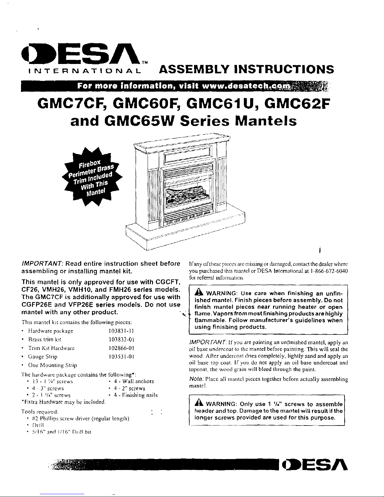
ASSEMBLING MANTEL
Straight leg models
I. Lay leg side on floor. Position leg as shown in Figure I. Align
predrilled screw holes in leg and kg side. Attach with three I 74"
wood screws
2. Place right and len legs on each side of heater.
Make sure face
of leg if flush with face of heater Slide header between right
and left legs. Make sure header and legs are
snug against heater
to ensure
a
tight fit (see Figure 2).
3
Locate predrilled holes
in mounting block on legs (see Figure
3). Attach to sides with two I 1/4" screws. The
top
of header
must be flush with top of legs. A gap may occur between
the
end of
the header and the legs.
4.
Remove leg assembly from heater. Turn top and leg assembly
upside down Place leg assembly inside top (see Figure 4).
The rear of legs should be flush with back of top and centered
left to right
5.
1 ocate predrilled holes in mounting blocks located on back of
header and sides (see Figure 5). Attach mantel assembly to top
with one I itt" screw in each block.
Top View
Left Leg
Left
Leg
Figure
4 -
Placing Mantel Assembly on Top
1 '14"
Screws
Predrilled
Hole
Prednlled
Hole
Note:
Fireplace and header may
differ slightly from illustration.
Mounting
Figure 2 - Installing Header
Blocks
Figure 5 - Securing Top to Sides
IIIIIC======t
108127-0113
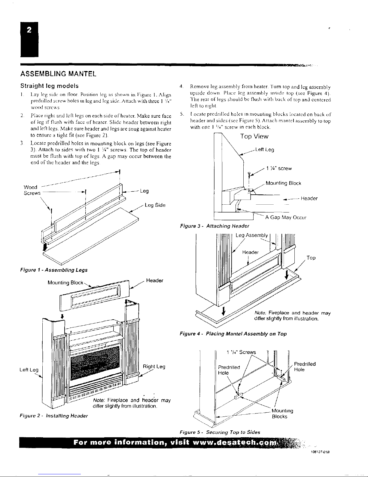
ASSEMBLING BRASS TRIM
Remove packaging from three remaining pieces of brass tom.
Locate two adjusting plates with set screws. and two shims in
the hardware packet.
Align shim under adjusting plate as shown in I igure 6
Slide
one end
of adjusting plimbshun
in
slot on
mitered edge
of top brass trim (see Figure 6)
Slide other end of adjusting plate: shim in slot on mitered edge
of side brass trim
(see
Figure 6)
While firmly holding edges of brass trim together. tighten both
set screws on the adjusting plate with slotted screwdriver.
Repeat steps I through 6 for other corner
Set
Top Brass Trim
'Mitered Edge
Side Brass Trim
Figure 6- Assembling Brass Trim
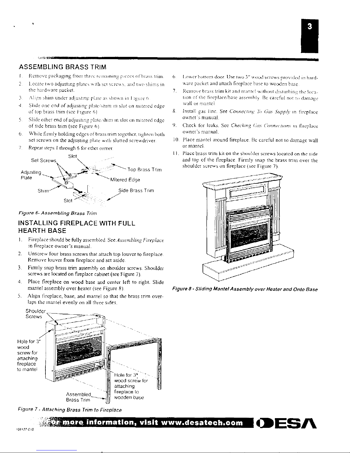
INSTALLING FIREPLACE WITH FULL
HEARTH BASE
I. Fireplace should be fully assembled See
Assembling Fireplace
in fireplace owner's manual.
2.
Unscrew four brass screws that attach top louver to fireplace.
Remove louver from fireplace and set
aside.
3.
Firmly
snap
brass trim assembly on shoulder screws. Shoulder
screws are located on fireplace cabinet (see Figure 7),
4.
Place fireplace on wood base and
center left to right.
Slide
mantel assembly over healer
(see Figure
8).
5.
Align fireplace,
base, and
mantel so
that the brass
trim over-
laps the mantel evenly on all three sides.
Shoulder
Screws
- LaJij
,
Hole for 3"
wood
screw for
I
attaching
fireplace
a
to mantel
a.
I Hole for 3''
-
wood screw for
attaching
Assembled
-
I
fireplace to
F
Brass Trim
—, I wooden base
6
lower bottom door Use two 3"
WO(Xl
screws provided in hard-
uare packet and attach fireplace base to
wocklen hase
7
Remove brass
trim
kit and
mantel without disturbing the
loca-
tion of the fireplace/base
assembly
Ile careful
not
to damage
wall
OF
mantel
8
Install gas line. See
Connecting
'/O Gas
Supply
in fireplace
owner's manual.
9.
Check for leaks. See
Checking Gas Connect/um
in fireplace
owner's manual.
10.
Place mantel around fireplace. Be careful not to damage wall
or mantel,
II. Place brass trim kit on the shoulder screws located on the side
and top of the fireplace. Firmly snap the brass trim over the
shoulder screws on fireplace (see Figure 7).
Figure 8-
Sliding Mantel Assembly over Heater and Onto Base
Adjustinc
Plate
Figure
7-
Attaching
Brass Trim to
Fireplace
= a
ESA
;08127 0,6
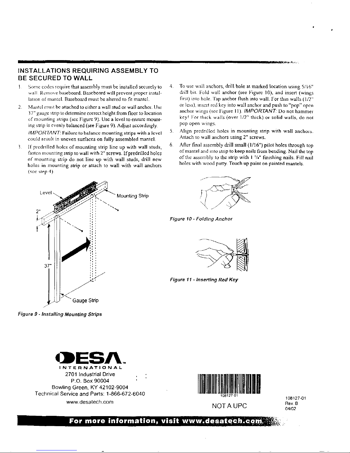
INSTALLATIONS REQUIRING ASSEMBLY TO
BE SECURED TO WALL
1 Some codes
require that assembly must be installed securely to
walk Remove baseboard. Baseboard will prevent proper instal-
lation of mantel. Baseboard must be altered to fit mantel.
2.
Mantel must be attached to either a wall stud or wall anchor. Use
:37" gauge stnp to determine correct height from floor to location
of mounting strips (sec Figure 9). Use
a
level to
ensure
11101111t-
ing
strip is evenly balanced (see Figure 9). Adjust accordingly.
IMPORTANT:
Failure to balance mounting strips with a level
could result in uneven surfaces on fully assembled mantel.
3.
If predrilled holes of mounting strip
line up
with wall studs,
fasten mounting strip to wall with 2" screws. If
predrilled holes
of mounting strip do not line up with wall studs, drill new
holes in mounting strip or attach to wall with
wall
anchors
(see step 4)
4.
To use wall
anchors, drill hole at marked location
using 5/16"
drill bit. Fold wall anchor (see Figure
10),
and insert (wings
first) into hole. Tap anchor flush into wall.
For thin
walls (1/2"
or less), insert
red key into wall anchor and push
to "pop" open
anchor wings (see Figure II).
IMPORTANT:
Do not hammer
key! For thick walls (over 112" thick) or solid walls, do not
pop open wings.
5.
Align predrilled holes in mounting strip with wall anchors.
Attach to wall anchors
using 2" screws.
6.
After final assembly drill small (1/16") pilot holes through
top
of mantel and into strip to keep nails from bending. Nail the top
of the assembly to the
strip with 1 '/4" finishing nails.
Fill nail
holes with wood putty. Touch up paint on painted mantels.
Level
Mounting Strip
Figure 10- Folding Anchor
Figure 11 - Inserting Red
Key
Gauge Strip
Figure 9 - Installing Mounting Strips
*MESA.
INTERNATIONAL
2701 Industrial Drive
P.O. Box 90004
Bowling Green, KY 42102-9004
Technical Service and Parts: 1-866-672-6040
www.desatech.com
T1111111111,1111111110
NOT A UPC
108127-01
Rev, B
04/02
C====.11).

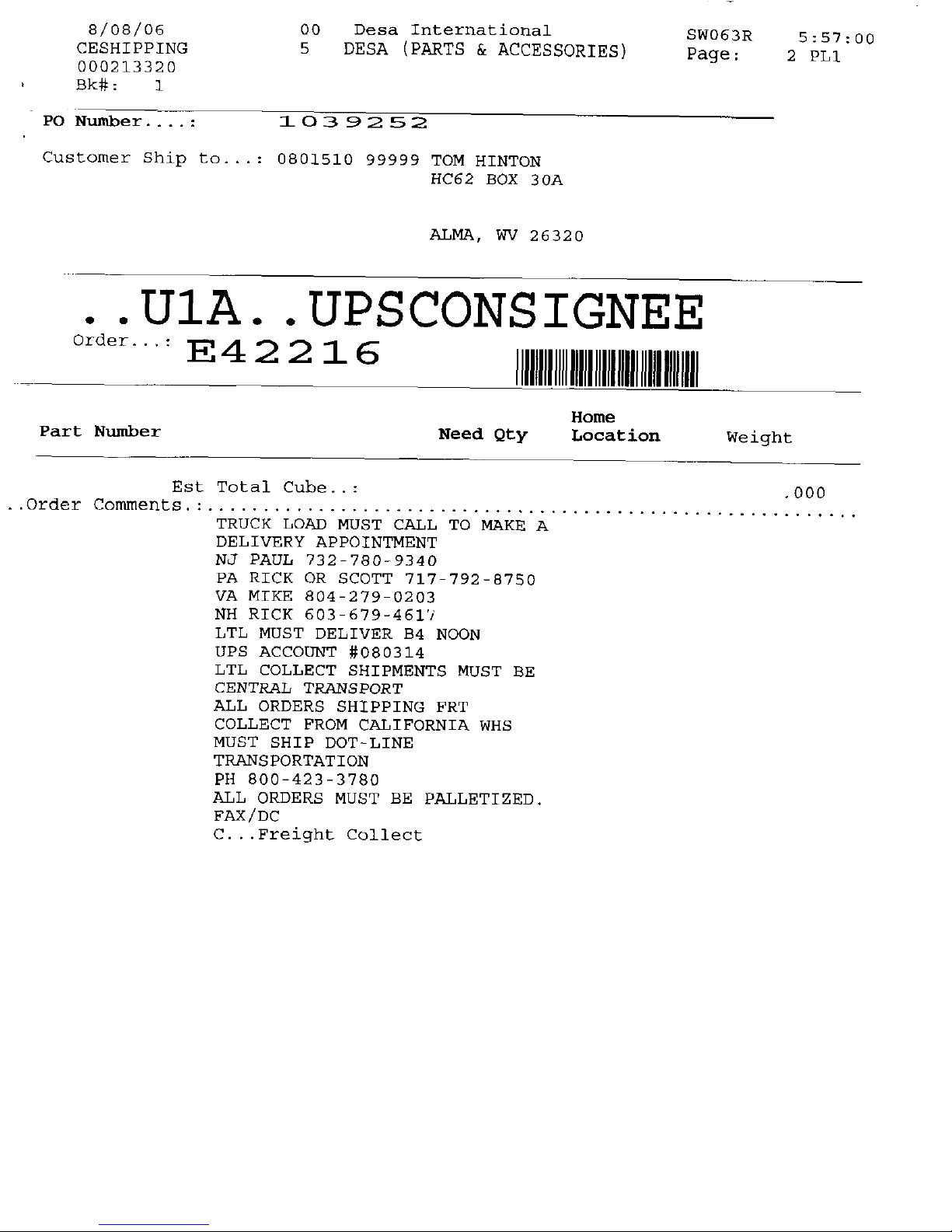
8/08/06
00 De sa International
CESHIPPING
5 DESA (PARTS & ACCESSORIES)
000213320
Bk# : 1
•
PO Number
1.0 3 9 2 5 2
Customer Ship to... : 0801510 99999 TOM MINION
HC62 BOX 30A
SW063R
Page:
5:57:00
1 PL1
ALMA, WV 26320
•
. UlA . . UPSCONS
IGNEE
Order...:
E42216
11111111
lID lull Ill DIII IIII 101 III
Part Number
MIEN IUMMUMINNIMINUMEI
Need Qty
Home
Location
Weight
099387 14
1
MS2064
040
....DescriptiOn..*:
TUBE,
PILOT
INNIEWHOIRMUMMININMENMUMEll
099387 IS
1 -
Z00804
001
....Description..*:
TUBE,
PILOT
099918 02
1-
MS3041
100
....Description..*:
REGULATOR, PILOT
1
D10062
300
103779 01
....Description..*:
PILOT,
O.D.S.
(Na)
103781 01
1
D10108
2.200
....Description..*:
VALVE, GAS
I/
11111111MMINIRIBRIMIIIMI
107186 02
1
Z01403
000
....Description..*:
INJECTOR
6
2.641
Total
•
(1/
8/08/06
CESHIPPING
000213320
Bk#:
1
00
Desa International
5
DESA (PARTS & ACCESSORIES)
SW063R
5:57:00
Page:
2
PL1
PO Number
-
203 9 2 52
Customer Ship to...: 0801510 99999 TOM HINTON
HC62 BOX 30A
ALMA, WV 26320
• .U1A. . UPSCONSIGNEE
Order...:
E 4 2 2 1 6
11111111ffinummuumn
Home
Part Number
Need Qty
Location
Weight
Est Total
Cuhe..:
.000
Order Comments •
TRUCK LOAD MUST CALL TO MAKE A
DELIVERY APPOINTMENT
NJ
PAUL 732-780-9340
PA
RICK OR SCOTT 717-792-8750
VA MIKE 804-279-0203
NH RICK 603
-
679-4617
LTL
MUST DELIVER B4 NOON
UPS ACCOUNT
#080314
LTL COLLECT SHIPMENTS MUST BE
CENTRAL TRANSPORT
ALL ORDERS SHIPPING FRT
COLLECT FROM CALIFORNIA WHS
MUST SHIP DOT-LINE
TRANSPORTATION
PH 800-423-3780
ALL ORDERS
MUST BE PALLETIZED.
FAX/DC
C...Freight Collect
MESA_
HEATING PRODUCTS
UNVENTED (VENT-FREE) GAS
COMPACT CLASSIC HEARTH
.
' FIREPLACE
OWNER'S OPERATION AND INSTALLATION MANUAL
O
w.
NM rftuarombend that bur
!moduli be instated mid
1 1:7
0 Codified
Pinr
; iii" I Jibr bbyt
WI {National Fintyloon Institute,.
CflflTlFttfl
www.nficertili•d. cm
Shown with optional cabinet mantel/hearth base accessory.
REMOTE-READY MODELS:
VMH26PRB, VMH26HRB, EFS26NRA, EFS26PRA
WARNING: If the information in this manual is not
followed exactly, a fire or explosion may result causing
property damage, personal injury, or loss of life.
—
Do not store or use gasoline or other flammable
vapors and liquids in the vicinity of this or any other
appliance.
—
WHAT TO DO IF YOU SMELL GAS
•
Do not try to light any appliance.
•
Do not touch any electrical switch; do not use any
phone in your building.
•
Immediately call your gas supplierfrom a neighbor's
phone. Follow the gas supplier's instructions.
•
If you cannot reach your gas supplier, call the fire
department.
—
Installation and service must be performed by a quali-
fied installer, service agency, or the gas supplier.
Save this manual for future reference.
For more Information, visit www.elesatech.com
WARNING: Improper installation, adjustment, altera-
tion, service, or maintenance can cause injury or prop-
erty damage. Refer to this manual for correct installation
and operational procedures. For assistance or addi-
tional information consult a qualified installer, service
agency, or the gas supplier.
WARNING: This is an unvented gas-fired heater. It uses
air (oxygen) from the room in which it is installed.
Provisions for adequate combustion and ventilation air
must be provided. Refer to Air for Combustion and
Ventilation section on page 6 of this manual.
This appliance may be installed in an aftermarket,*
permanently located, manufactured (mobile) home,
where not prohibited by local codes.
This appliance is only for use with the type of gas
indicated on the rating plate. This appliance is not
convertible for use with other gases.
Aftermarket: Completion of sale, not for purpose of resale, from the
manufacturer
TABLE OF CONTENTS
Safety Information
Product Identification
Optional Remote Control Accessories
Local Codes
Product Features
Unpacking
Assembly
Air For Combustion and Ventilation
Installation
Operating Fireplace
Inspecting Burners
3
4
5
5
5
5
5
6
9
22
25
Cleaning and Maintenance
26
Wiring Diagram
27
Troubleshooting
28
Specifications
32
Replacement Parts
33
Service Hints
33
Technical Service
33
Illustrated Pans Breakdown and Parts Ts!
34
Accessories
36
Warranty Information
Back Cover
www.desatech.com
113110-01B
SAFETY INFORMATION
A
WARNING: This product con-
tains and/or generates chemi-
cals known to the State of Cali-
fornia to cause cancer or birth
defects, or other reproductive
harm.
IMPORTANT: Read this owner's
manual carefully and completely
before trying to assemble, oper-
ate, or service this fireplace. Im-
proper use of this fireplace can
cause serious injury or death
from burns, fire, explosion, elec-
trical shock, and carbon mon-
oxide poisoning.
A
DANGER: Carbon monoxide
poisoning may lead to death!
Carbon Monoxide Poisoning: Early signs of car-
bon monoxide poisoning resemble the flu, with head-
aches, dizziness, or nausea. If you have these signs,
the fireplace may not be workmg properly. Get fresh
air at once! Have fireplace serviced. Some people
are more affected by carbon monoxide than others.
These include pregnant women, people with heart
or lung disease or anemia, those under the influence
of alcohol, and those at high altitudes.
Natural and Propane/LP Gas: Natural and propane/
IT gases are odorless. Art odor-making agent is
added to the gas. The odor helps you detect a gas
leak. However_ the odor added to the gas can fade.
Gas may be present even though no odor exists.
Make certain you read and understand all warn-
ings. Keep this manual for reference. It is your
guide to safe and proper operation of this fireplace.
A
WARNING: Any change to
this fireplace or its controls can
be dangerous.
A
WARNING: Do not use a
blower insert, heat exchanger in-
sert, or other accessory not am
proved for use with this fireplace.
A
WARNING: Do not allow fans
to blow directly into thefireplace.
Avoid any drafts that alter burner
flame patterns. Ceiling fans can
create drafts that alter burner
flame patterns. Altered burner
patterns can cause sooting.
Due to high temperatures, the
appliance should be located out
of traffic and away from furni-
ture and draperies.
Do not place clothing or other
flammable material on or near
the appliance. Never place any
objects on the heater.
Fireplace front and screen be-
come very hot when running
heater. Keep children and adults
away from hot surfaces to avoid
burns or clothing ignition. Fire-
place will remain hot for a time
after shutdown. Allow surfaces
to cool before touching.
Carefully supervise young chil-
dren when they are in the room
with fireplace. When using the
hand-held remote accessory
keep selector switch in the OFF
position to prevent children from
turning on burners with remote.
You must operate this fireplace
with the fireplace screen in place.
Make sure fireplace screen Is
closed before running fireplace.
Keep the appliance area clear
and free from combustible ma-
terials, gasoline, and other flam-
mable vapors and liquids.
11311001B
www.desateetteorn
3
SAFETY INFORMATION
Continued
1.
This appliance is only for use with the type of
gas indicated on the rating plate. This appli-
ance is not convertible for use with other
gases.
2.
Do not place propanelLP supply tank(s) in-
side any structure. Locate propane/LP supply
tank(s) outdoors.
3.
If you smell gas
•
shut off gas supply
•
do not try to light any appliance
•
do not touch any electrical switch; do not
use any phone in your building
•
immediately call your gas supplier from a
neighbor's phone. Follow the gas supplier's
instructions
•
if you cannot reach your gas supplier, call
the lire department
4.
This fireplace shall not he installed in a bath-
room or bedroom.
5.
Do not
use
this fireplace as a wood-burning
fireplace. Use only the logs provided with the
fireplace,
O. Do not add extra logs or ornaments such as
pine cones, vemitillite. or rock wool. Using
these added items can cause sooting. Do not
add lava rock around base_ Rock and debris
could fall into the control area of fireplace.
7.
This fireplace is designed to be smokeless. If
logs ever appear to smoke, turn off fireplace
and call a qualified service person.
Note:Dur-
ing
initial operation, slight smoking could oc-
cur due to log curing and fireplace burning
manufacturtng residues.
8.
To prevent the creation of soot, follow the
instructions in
Cleaning and Maintenance,
page 26.
9.
Before using furniture polish, wax, carpet
cleaner, or similar products, turn fireplace off.
If heated, the vapors thorn these products may
create a white powder residue within burner
box or on adjacent walls or furniture.
10.
This fireplace needs fresh air ventilation to
run properly. This fireplace has an Oxygen
Depletion Sensing (BUS) safety shutoff sys-
tem. The ODS shuts down the fireplace if not
enough fresh air is available, See
Air fur Com.
bastion and Ventilation.
pages 6 through S. If
fireplace keeps shutting off, see Troubleshoot-
ing,
pages 28 through 31.
II, Do not run fireplace
•
where flammable liquids or vapors are used
or stored.
•
under dusty conditions.
12.
Do not use this fireplace to cook food or bum
paper or other objects,
13.
Never place any objects in
the
fireplace or
on logs,
14.
Do not use fireplace if any part has been wader
water. Immediately call a qualified service tech-
nician to inspect the room lisepincie and to re-
place any part of the control system and any
gas control which has been under water
IS. Turn off and unplug fireplace and let cool be-
fore servicing. Only a qualified
service
per-
son should service and repair fireplace.
16.
Operating fireplace above elevations of 4,500
feet could cause pilot outage.
17.
Do not operate fireplace if any log is broken.
Do not operate fireplace if a
log
is chipped
(dime-sized or larger).
18.
To prevent perforniance problems, do not use pm-
pane/LP fuel tank of less than 100 Ins. capacity.
19.
Provide adequate clearances around air
openings.
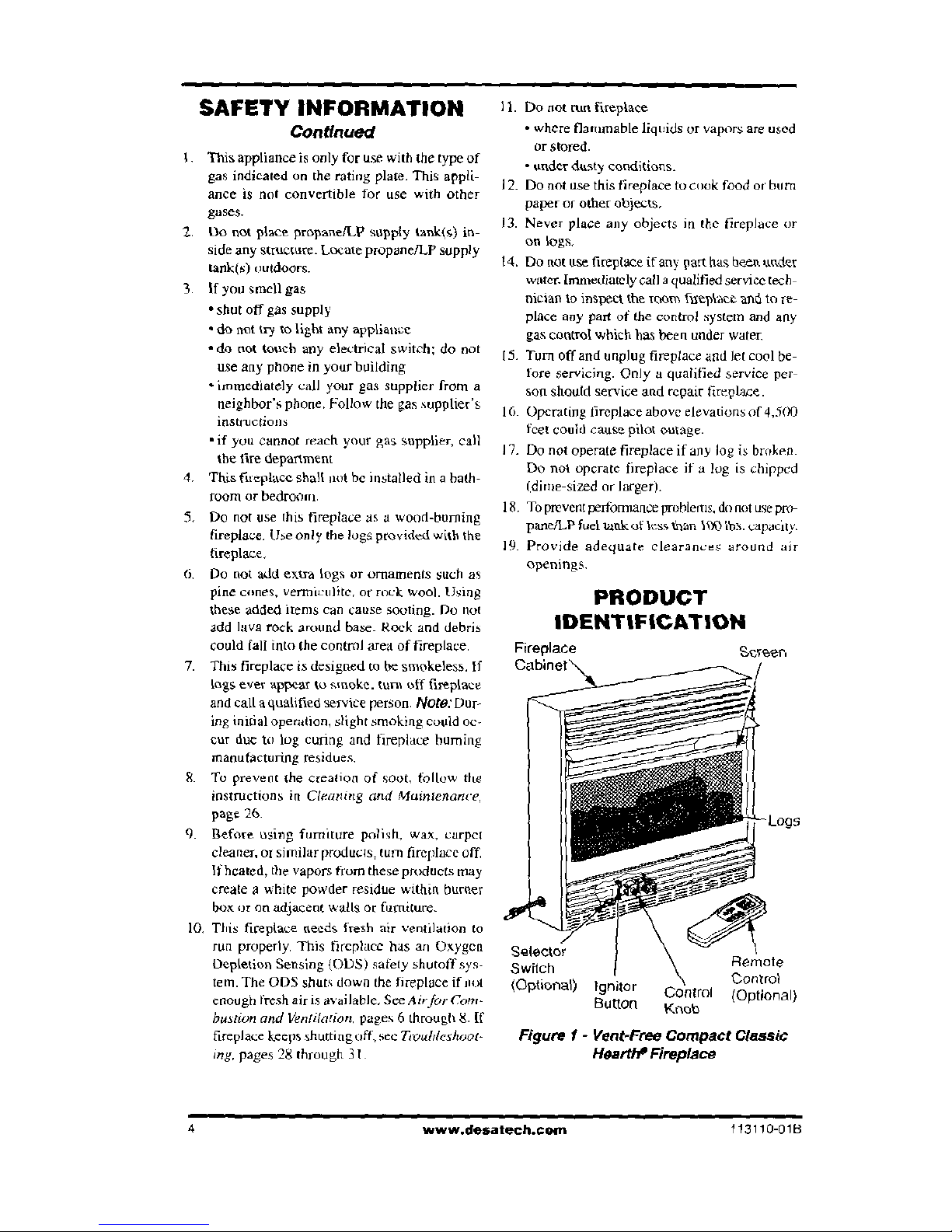
PRODUCT
IDENTIFICATION
ace
Screen
,
-
Selector
Remote
Switch
Control
(Optional) Ignitor
Control (Optional)
Button
K
no
t)
Figure f - Vent-Free Compact Classic
Hearth* Fireplace
4
www.desatech.cogn
113110-0113
OPTIONAL REMOTE
CONTROL ACCESSORIES
There are four optional remote controls that can
be purchased separately:
•
wall twitch
•
hand-held ON/OFF remote
•
wall thermostat
•
hand-held thermostat remote
See
Accessories,
pages 36 and
37.
LOCAL CODES
Instal/ and use fireplace with care. Follow all lo-
cal codes, In the absence of local codes, use the
latest edition of 7he
National Fuel Gas Code ANSI
Z223.1/NFPA 54*,
*Available from:
American National Standards Institute. Inc.
1430 Broadway
New York. NY 10018
National Fire Protection Association, Inc.
Batterymarch Park
Quincy, MA
02269
PRODUCT FEATURES
SAFETY PILOT
This fireplace has a pilot with an Oxygen Deple-
tion Sensing (ODS) safety shutoff system. The
ODSMilot is a required feature for vent-free room
fireplaces. The ODS/pilot shuts off the fireplace
it there is not enough fresh air.
PIEZO IGNITION SYSTEM
This fireplace has a piezo ignitor This system in
quires no matches, batteries. or other sources to
light fireplace.
UNPACKING
I
•
Remove fireplace and hood from carton. Log
is wrapped and inside fireplace. Do not re-
move at this time.
2.
Remove all protective packaging applied to
fireplace for shipment.
3.
Make sure your fireplace includes one hard-
ware packet.
4.
Check fireplace for any shipping damage. If
fireplace is damaged, promptly inform dealer
where you bought fireplace.
ASSEMBLY
A
WARNING:
Always have
branch support and screen in
place before operating fireplace.
This prevents excessive tem-
peratures on fireplace surfaces.
A
WARNING: Failure to posi-
tion the parts in accordance
with these diagrams or failure
to use only parts specifically
approved with this fireplace
may
result
in property damage
or
personal injury.
ASSEMBLING FIREPLACE
Tools Required:
•
Phillips screwdriver
•
5/16" hex wrench
•
slotted screwdtiver
•
scissors
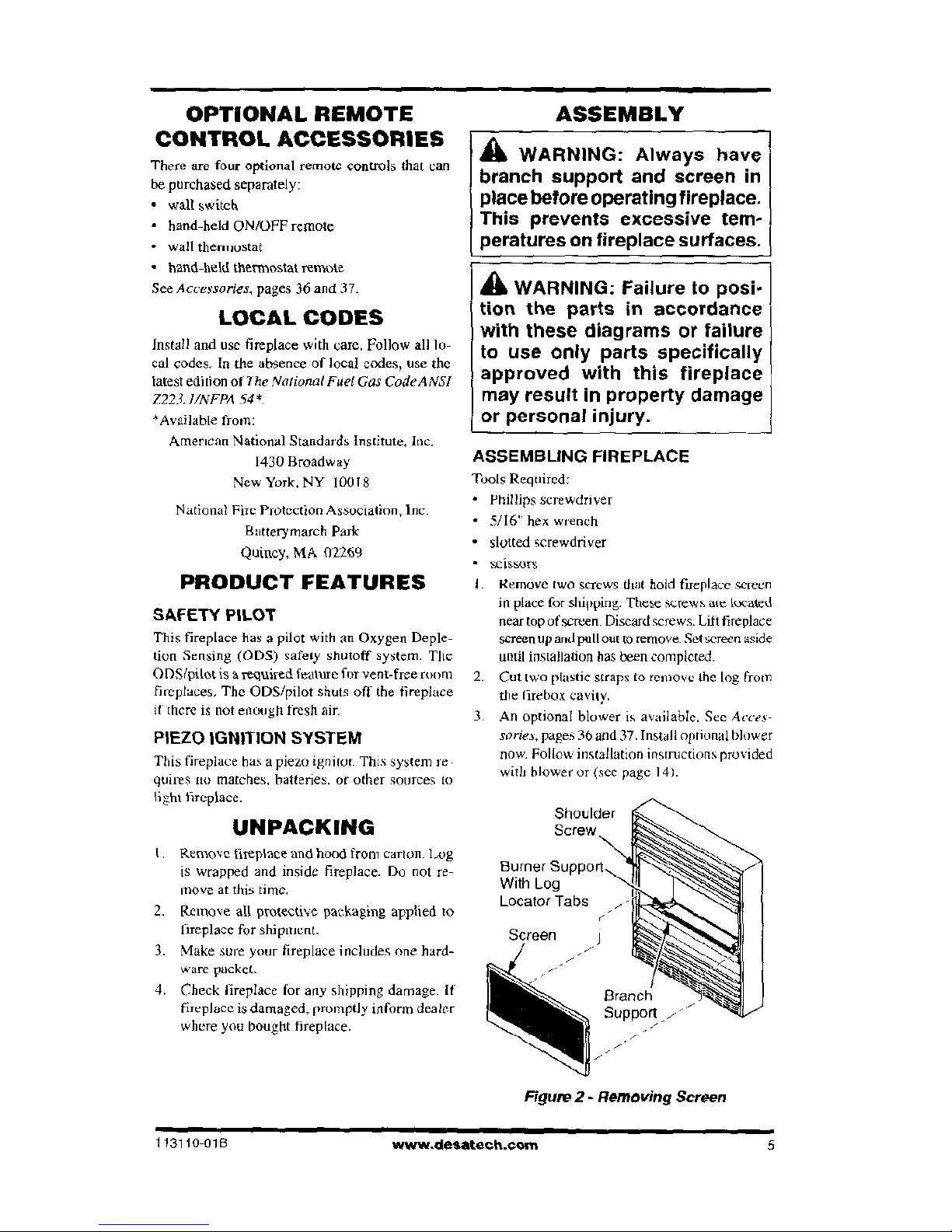
I. Remove two screws dial hold fireplace screen
in place for shinning. These screws are located
near top of screen. Discard screws. Litt fireplace
screen up and pull out to remove. Set screen aside
until installation has been completed.
2.
Cut
NVO
plastic straps to remove the log from
the firebox cavity.
3.
An optional blower is available. See
Acces-
sories,
pages 36 and 37. Install optional blower
now. Follow installation instructions provided
with blower or (sec page 141.
Shoulder
Burner Support
I'
Locator Tabs
NS
c
%
-
Branch
I
Figure 2- Removing Screen
113110-018
www-desatech.com
5
ASSEMBLY
Continued
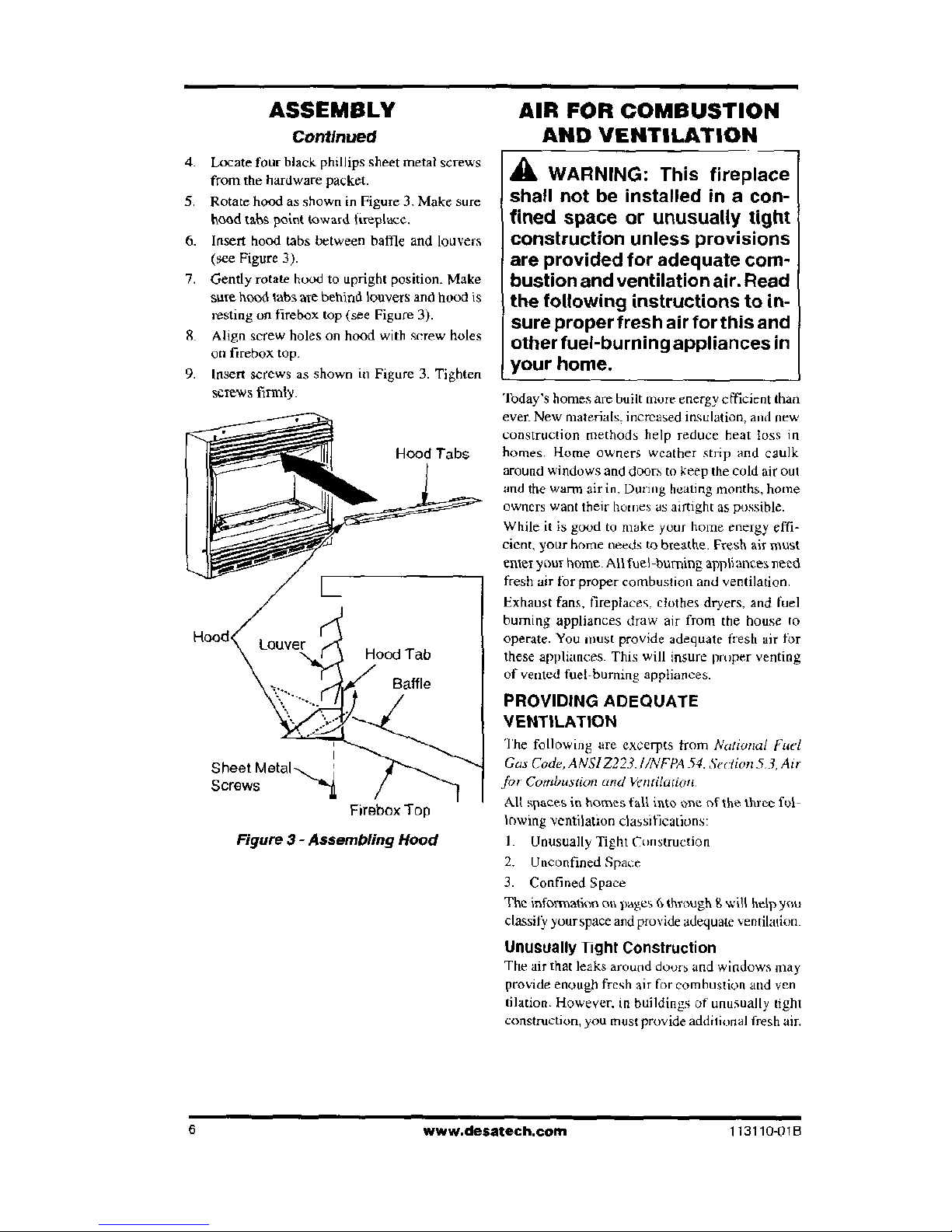
4.
Locate four black phillips sheet metal screws
from the hardware packet.
5.
Rotate hood as shown in Figure 3. Make sure
hood tabs point toward fireplace..
6.
Insert hood tabs between baffle and louvers
(see Figure 3).
7.
Gently rotate hood to upright position. Make
sure hood tabs are behind louvers and hood is
resting on firebox top (see Figure 3).
8.
Align screw holes on hood with screw holes
on firebox
top.
9.
Insert screws as shown in Figure 3. Tighten
Screws
firmly
Figure 3 - Assembling Hood
AIR FOR COMBUSTION
AND VENTILATION
A
WARNING:
This fireplace
shall not be installed in a con-
fined space or unusually tight
construction unless provisions
are provided for adequate com-
bustion and ventilation air. Read
the following instructions to in-
sure proper fresh air for this and
other fuel-burning appliances in
your home.
Today's homes are built more energy efficient than
ever. New materials, increased insulation, and new
construction methods help reduce heat loss in
homes, Home owners weather strip and caulk
around windows and doors to keep the cold air out
and the warm air in. During heating months, home
owners want their homes as airtight as possible.
While it is good to make your home energy effi-
cient, your home needs to breathe. Fresh air must
enter your home. All fuel-burning appliances need
fresh air for proper combustion and ventilation.
Exhaust fans, fireplaces. clothes dryers, and fuel
burning appliances draw air from the house to
operate. You must provide adequate fresh air for
these appliances. This will insure printer venting
of vented fuel-burning appliances.
PROVIDING ADEQUATE
VENTILATION
The following are excerpts from
National Fuel
Gas Code, A A 151 Z223. UNITA 54. Sedion 53, Air
for Combustion and Ventilation.
All spaces in homes fall into one of the three fol-
lowing ventilation classifications:
I. Unusually Tight Construction
2.
Unconfined Space
3.
Confined Space
The information
on pages
6through g will help you
classify your space and provide adequate ventilation.
Unusually Tight Construction
The air that leaks around doors and
windows
may
provide enough fresh air for combustion and yen
Illation. However, in buildings of unusually tight
construction, you must provide additional fresh air.
6
www.desatech.com
1131104)IB
AIR FOR COMBUSTION
AND VENTILATION
Continued
Unusually tight construction is defined as
construction where:
a.
walls and ceilings exposed to the out-
side atmosphere have a continuous
water vapor retarder with a rating of
one perm (6 x 10
-
" kg per pa-sec-m
2
)
or less with openings gasketed or
sealed
and
b.
weather stripping has been added on
openable windows and doors
and
c.
caulking or sealants are applied to ar-
eas such as joints around window and
door frames, between sole plates and
floors, between wall-ceiling joints, be-
tween wall panels, at penetrations for
plumbing, electrical, and gas lines, and
at other openings.
If your home meets all of these three crite-
ria, you must provide additional fresh air.
See
Ventilation Air From Outdoors,
pages.
If your home does not meet all of the three
criteria above, proceed to Determining Fresh-
Alr
Row For Fireplace Location,
below.
Confined and Unconfined Space
The
National Fuel Gas Code, ANSI 1223.I/NFPA
54
defines a confined space as a space whose vol-
ume is less than SO cubic feet pee
1,000 RR,
per
hour (4.8
in
3
per kw) of the aggregate input rating
of all appliances installed in that space and an un-
confined space as a space whose volume is not
less than 50 cubic feet per 1,000 Btu per hour (4.8
m3 per kw ) of the aggregate input rating of all ap-
pliances installed in that space. Rooms communi-
cating directly with the space lit which the appli-
ances are installed*, through openings not fur-
nished with doors, are considered a part of the
unconfined Space.
*Adjoining rooms are communicating only if there
are doorless passageways or ventilation grills be-
tween them.
DETERMINING FRESH-AIR FLOW
FOR FIREPLACE LOCATION
Determining
it
Y ou Have a Confined or
Unconfined Space
Use this work sheet to determine if you have a
confined or unconfined space.
Space:
Includes the room in which you will in-
stall fireplace plus any adjoining rooms with
doorless passageways or ventilation grills between
the rooms_
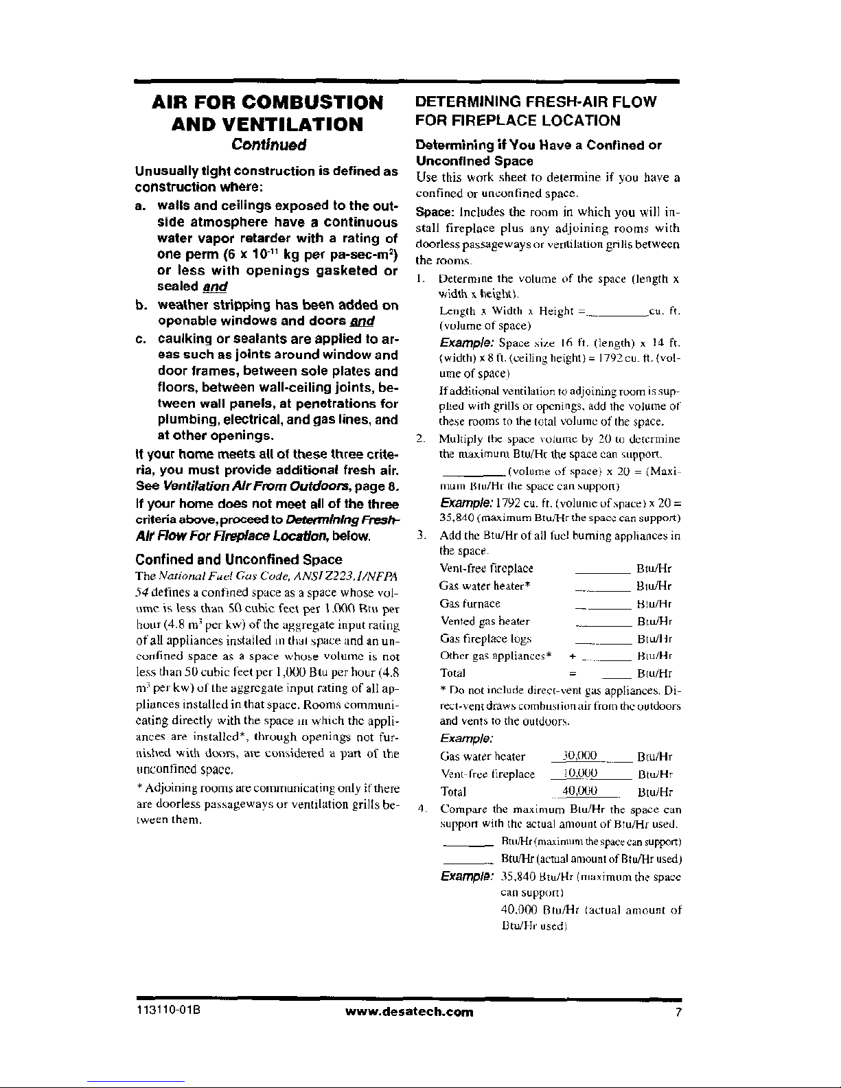
I. Determine the volume of the space (length x
width s height).
Length x Width s Height =
cu. ft.
(volume of space)
Example:
Space site id ft. (length) x 14 ft.
(width) x 8 it. (ceiling height) = 1792 Cu- ft. (vol-
ume of space)
If additional ventilation to adjoining room is sup-
plied with grills or openings, add the volume of
these rooms to the total volume of the space.
2. Multiply the space volume by 20 to determine
the maximum Btu/Ht the space cart support.
(volume of space) x 20 = (Maxi-
mum lituAir the space can support)
Example:
1792 cu. ft. (volume uf space) x 20 =
35,840 (maximum Btunir the space can support)
1. Add the Bra/Hr of all fuel burning appliances in
the space_
Vent-free fireplace
Eta/Hr
Gas water heater*
Btu/Hr
Gas furnace
Blu/Hr
Vented gas heater
BuilkIr
Gas fireplace lugs
Btu/I lr
Other gas appliances*
+
Biu/lir
Total
Btu/Hr
* Do not include direct-vent gas appliances. Di-
rect-vent draws combustion air from the outdoors
and vents to the outdoors.
Example:
Gas water heater
30,000
Btu/Hr
Vent-free fireplace
10.000
Btu/Hr
Total
40,000
Litu/Hr
Compare the maximum Biu/Hr the space can
suppon with the actual amount of Btu/Hr used.
Fltit/HrUnaximuni the spaeecan support)
Btu/Hr (actual amount of Rtuflir used)
Example:
35.840 Btu/Hr (maximum the space
can support)
40,000 Btu/Hr I actual amount of
Btu/Hr used)
113110 01B
www.desatech-com
7
AIR FOR COMBUSTION
AND VENTILATION
Continued
The space in the above example is a confined space
because the actual Btu/Hr used is more than the
maximum BM/Iir the space can support. You
must
provide additional fresh air. Your options are as
follows:
A.
Rework worksheet, adding the space of an ad-
joining room. If the extra space provides an
unconfined space, remove door to adjoining
room or add ventilation grills between rooms.
See
Ventilation Air From Inside Building
B. Vent
MOM
directly to the outdoors. See
Venti-
lation Air From Outdoors_
C .
Install a lower Btu/HI-fireplace, if lower Btuillr
size makes room unconfined.
If the actual Rtufblr used is less than the maxi-
mum Blair the space can support, the space is
an unconfined space. You will need no additional
fresh air ventilation.
AA
WARNING: If
the area in
which the fireplace may be op-
erated is smaller than that de-
fined as an unconfined space or
if the building is of unusually
tight construction, provide ad-
equate combustion and ventila-
tion air by one of the methods
described in the
National Fuel
Gas Code, ANSI Z223.1/NFPA
54 Section
5.3 or applicable lo-
cal codes,
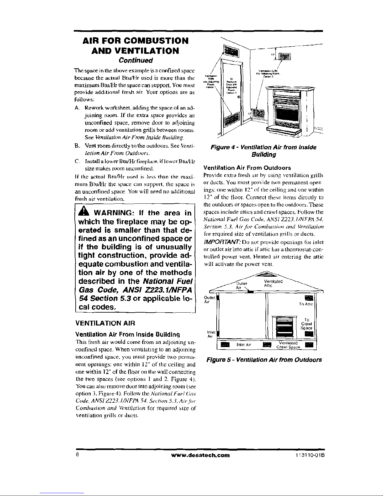
VENTILATION AIR
Ventilation Air From Inside Building
This fresh air would come from an adjoining un-
confined space. When ventilating to an adjoining
unconfined space, you must provide two perma-
nent openings: one within
I
2" of the ceiling and
one within 12" of the floor on the wall connecting
the
two
spaces (sec options 1 and 2, Figure 4).
You can also remove dour into adjoining room (see
option I Figure 4). Follow the
National Fuel Gas
Code, ANSI /223. 1/NFPA 54. Section 5.3. Air the
Combustion and Ventilation
for required size of
ventilation grills or ducts.
Figure 4- Ventilation Air from inside
Building
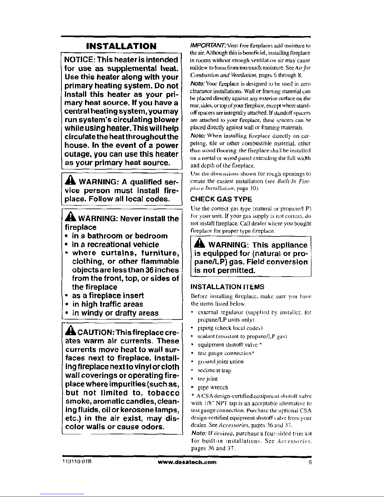
Ventilation Air From Outdoors
Provide extra fresh air by using ventilation grills
or ducts. You must provide two permanent open
ings: one within 12" of the ceiling and one within
12" of the floor. Connect these items directly to
the outdoors or spaces open to the outdoors. These
spaces include attics and crawl spaces. Follow the
National. Fuel Gas Code, ANSI /223.1/NEPA 54.
Section 53. Air for Cumbustiem and Ventilation
for required size of ventilation grills or duets.
IMPORTANT
-
Do not provide openings for inlet
or outlet air
into attic if attic has a thermostat-con-
trolled power vent. Heated air entering the attic
will activate the power vent.
/Cutlet
Ventdated
Attie
Air
Outlet
Air
To Attic
"
et
"
CvratinIn
tea
a„e
Figure 5- Ventilation Air from Outdoors
www.desateeh.com
113110-01B
INSTALLATION
NOTICE: This heater is intended
for use as supplemental heat.
Use this heater along with your
primary heating system. Do not
Install this heater as your pri-
mary heat source. If you have a
central heating system, you may
run system's circulating blower
while using heater. This will
help
circulate the heat throughoutthe
house. In the event of a power
outage, you can use this heater
as your primary heat source.
A
WARNING: A qualified ser-
vice person must Install fire-
. place. Follow all local codes.
A
WARNING: Never install the
fireplace
•
in a bathroom or bedroom
•
in a recreational vehicle
•
where curtains, furniture,
clothing, or other flammable
objects are less than 36 inches
from the front, top, or sides of
the fireplace
•
as a fireplace insert
•
in high traffic areas
•
in windy or drafty areas
A
CAUTION: This fireplace cre-
ates warm air currents. These
currents move heat to wall sur-
faces next to fireplace. Install-
ing fireplace next to vinyl or cloth
wall coverings or operating fire-
place where impurities (such as,
but not limited to, tobacco
smoke, aromatic candles, clean-
ing fluids, oil or kerosene lamps,
etc.) in the air exist, may dis-
color walls or cause odors.
IMPORTANT-Vent-free
fireplaces add moisture to
the air. Although this is beneficial, installing fireplace
in rooms without enough ventilation air may cause
mildew to fonts from too much moisture, See Airfor
Combustion and Ventilation,
pages 6 through 8.
Note:
Your fireplace is designed to be used in zero
clearance installations. Wall or framing material can
be placed directly against any exterior surface on the
rear, sides, or top of your fireplace, except where stand-
off spacers are integrally attached. If standoff spacem
are attached to your fireplace, these spacers can be
placed directly against wall or framing materials.
Note:
When installing fireplace directly on car-
peting, tile or other combustible material, other
than wood flooring, the fireplace shall be installed
on a metal or wood panel extending the full width
and depth of the fireplace.
Use the dimensions shown for rough openings to
create the easiest installation (see
Built-1n Fire-
place Installation,
page
10).
CHECK GAS TYPE
Use the correct gas type (natural or propaned P)
for your ann. If your gas supply it not collect, do
not Install fireplace. Call dealer where you bought
fireplace for proper type fireplace
A
WARNING: This appliance
is equipped for (natural or pro-
pane/LP) gas. Field conversion
is not permitted.
INSTALLATION ITEMS
Before installing fireplace, make sure you have
the items listed below.
•
external regulator (supplied hy installer, for
propane/LP units only)
•
piping (check local codes)
•
sealant (resistant to propane/LP gas)
equipment shutoff valve *
test gauge connection*
mound joint union
sediment trap
•
tee joint
•
pipe wrench
* A USA design-certified cduiPmenl
00011
"Ye
with I/8" NPT tap is an acceptable alternative to
test gauge connection. Purchase the optional CSA
design-certified equipment shutoff valve from your
dealer. See
Accessories,
pages 36 and 37.
Note:
If desired, purchase a four-sided trim kit
for builton installations. See A
ccessoricr,
pages 36 and 37,
113110-01B
www.desatech.com
9
INSTALLATION
Continued
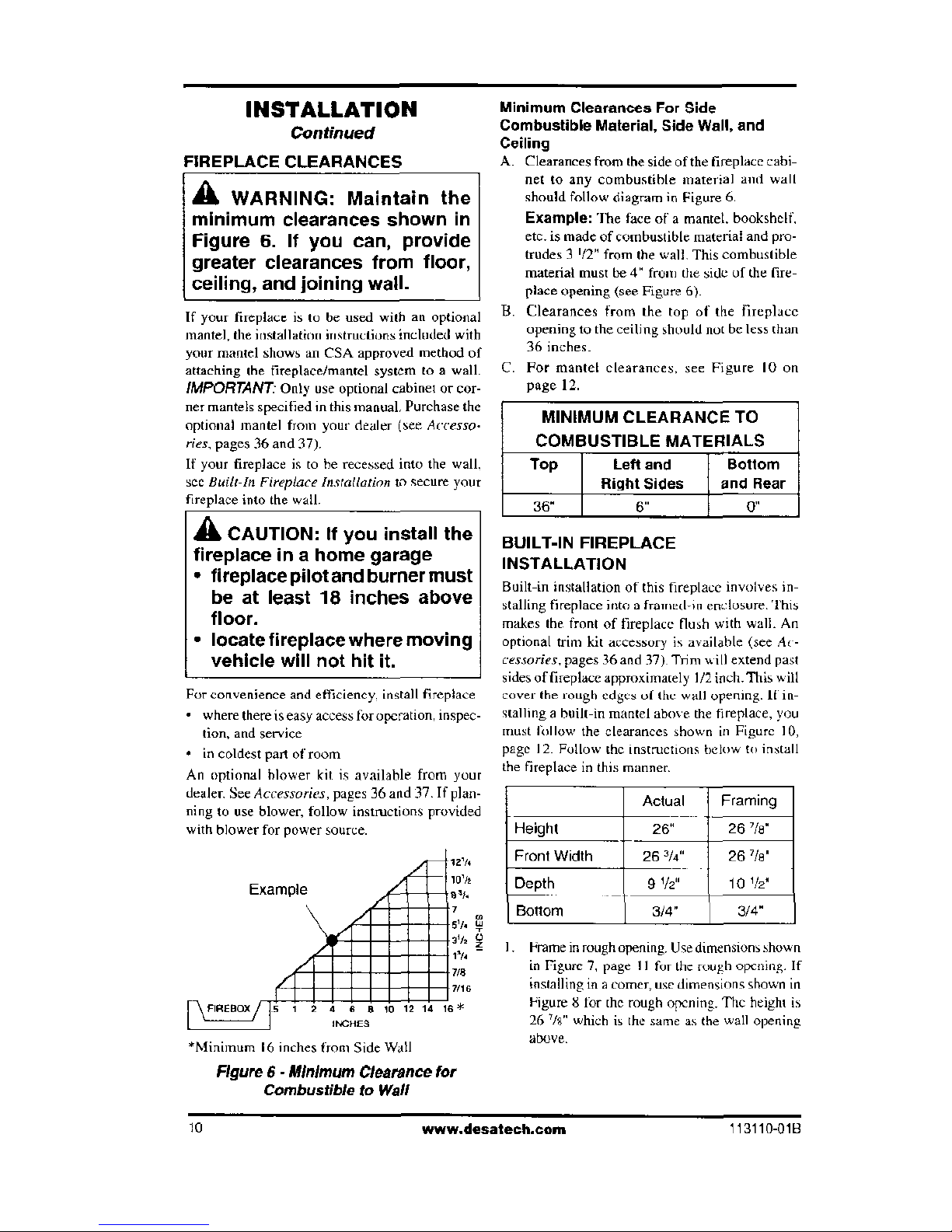
FIREPLACE CLEARANCES
A
WARNING: Maintain the
minimum clearances shown in
Figure 6. If you can, provide
greater clearances from floor,
ceiling, and joining wall.
If your fireplace is to be used with an optional
mantel, the installation instructions included with
your mantel shows an CSA approved method of
attaching the fireplace/mantel system to a
wall.
IMPORTANT
-
Only use optional cabinet or cor-
ner mantels specified in this manual. Purchase the
optional mantel from your dealer (see
Access°.
des,
pages 36 and 37).
If your fireplace is to he recessed into the wall.
see
Built-1n Fireplace Installation
to secure your
fireplace into the wall.
A
CAUTION: If you install the
fireplace in a home garage
•
fireplace pilot and burner must
be at least 18 inches above
floor.
•
locate fireplace where moving
vehicle will not hit it.
For convenience and efficiency, install fireplace
•
where there is easy access for operation, inspec-
tion, and service
•
in coldest part of room
An optional blower kit is available from your
dealer. See
Accessories,
pages 36
and 37. If plan-
ning to use blower,
follow instructions provided
with blower for power source.
Example
ain
9 m
Ann,
/ L
T,
411Mini. :.;
6
siIMMIEN
MCHES
*Minimum 16 inches from Side Wall
Minimum Clearances For Side
Combustible Material, Side Wall, and
Ceiling
A.
Clearances from the side of the fireplace cabi-
net to any combustible material and wall
should follow diagram in Figure 6.
Example:
The face of a mantel, bookshelf,
etc. is made of combustible material and pro-
trudes 3 '/2"
from
the
wall. This combustible
material must be 4" from the side of the fire-
place opening (see Figure 6).
B.
Clearances from the top of the fireplace
opening to the ceiling should not be less than
36 inches.
C.
For mantel clearances, see Figure 10 on
page 12.
MINIMUM CLEARANCE TO
COMBUSTIBLE MATERIALS
Top Left and Bottom
Right Sides
and Rear
36"
BUILT-IN FIREPLACE
INSTALLATION
Built-in installation of this fireplace involves in-
stalling fireplace into a framed-in enclosure. This
makes the front of fireplace flush with wall. An
optional trim kit accessory is available (see
Ac-
cessories,
pages 36 and 37). Trim will extend past
sides of fireplace approximately 1/2 inch. This will
cover the rough edges of the wall opening. It In-
stalling a built-in mantel above the fireplace, you
must follow the clearances shown in Figure 10,
page 12. Follow the instructions below to install
the fireplace in this manner.
Actual
Framing
Height
261
26 '/8"
Front Width
26
/4"
26
5
/8"
Depth
91/f
10 l/21'
Bottom
3/4" 3/4"
I. Frame in rough opening. Use dimensions shown
in Figure 7, page 11 for the rough opening. If
installing in a comer, use dimensions shown in
Figure 8 for the rough opening. The height is
26 78" which is the same as the wall opening
above.
Figure 6 - Minimum Clearance for
Combustible to Wall
10
www.desatech.com
113110-018
/
343/4"
'7 \tie
IXli
-
St
INSTALLATION
Continued
2.
It installing GA3450T blower accessory, do
so at this time. Follow instructions included
with blower accessory.
Note:
If not installing blower accessory, you
may wish to run electrical wiring to your fire-
place for future blower installation (see
Ac-
cessories,
pages 36 and 37). Use only ap-
proved three-wire electrical wiring.
Note: k
qualified Msuiller should make all
electrical connections.
A
WARNING: If pre-wiring, do
not connect wiring to any elec-
trical source at this time.
Install fireplace electrical outlet
and connect wiring to outlet be-
fore connecting to electrical
source. The fireplace electrical
outlet is included with the
GA3450T blower accessory.
Only use the fireplace electrical
outlet supplied with the
GA3450T blower accessory.
3.
Install gas piping to fireplace location. This
installation includes an approved flexible gas
line Cif allowed by local codes.) after the equip-
went shutoff valve. The flexible gas line must
be the last item installed on the gas piping_
' Ott
Floor
imum
Figure 7 - Rough Opening for Installing
in Wall
4.
If you have not assembled firebox, follow in-
structions beginning on page 5.
5.
Carefully set fireplace in front of rough open-
ing with back of fireplace inside wall opening.
6.
Attach flexible gas line to fireplace gas Tegu-
lator. See
Connecting Fireplace to
Gus
Sup-
ply,
pages 17 and 18.
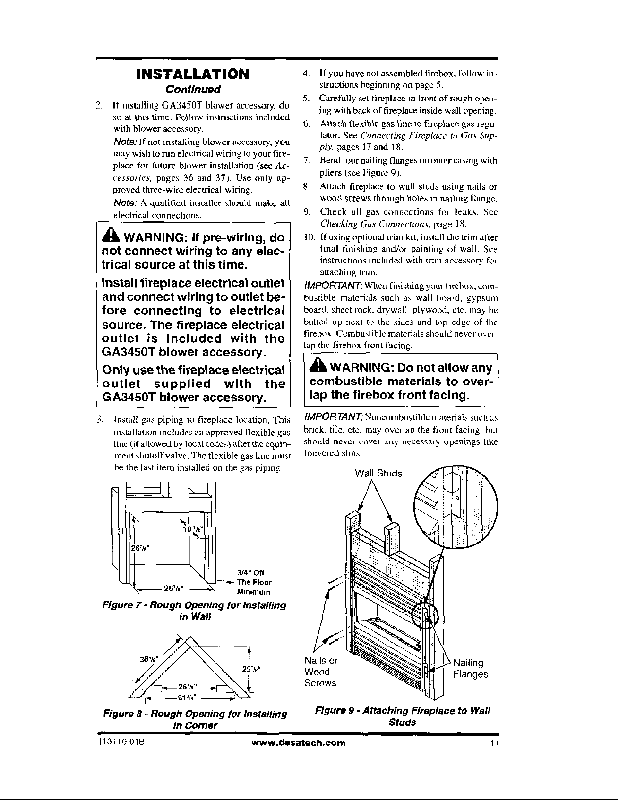
7.
Bend four nailing flanges on outer casing with
pliers (see Figure 9).
8.
Attach fireplace to wall studs using nails or
wood screws through holes in nailing flange.
9.
Check all gas connections for leaks. See
Checking Gas Connections,
page 18.
10.
If using optional trim kit, install the trim after
final finishing and/or painting of wall. See
instructions included with trim accessory for
attaching trim.
IMPORTANT:Whenfinishing
your firebox, com-
bustible materials such as wall board. gypsum
board, sheet rock, drywall, plywood, etc. may be
butted up next to the sides and top edge of the
firebox_ Combustible materials should never over-
lap the firebox front facing.
A
WARNING: Do not allow any
combustible materials to over-
lap the firebox front facing.
IMPORTANT
-
Noncombustible materials such as
brick, tile, etc. may overlap
the
front facing, but
should never cover any necessaty openings like
louvered slots.
Figure 8- Rough Opening for Installing
Figure 9 - Attaching Fireplace to Wall
in Corner
Studs
113110-018
www.desatech.com
11
INSTALLATION
Continued
AWARNING: Do not allow non-
combustible materials to cover
any necessary openings like
louvered slots.
A
WARNING: Never modify or
cover the louvered slots on the
front of the firebox.
A
WARNING: Useonly noncom-
bustiblemortaroradhesiveswhen
overlapping the front facing with
noncombustible facing material.
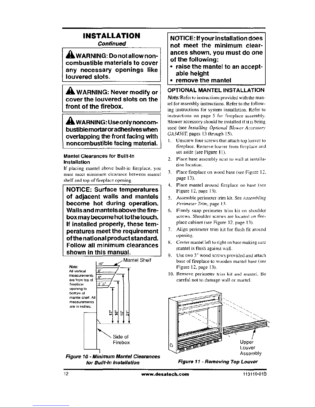
Mantel Clearances for Built-In
Installation
If
placing
mantel above built-in fireplace, you
must meet minimum
clearance
between mantel
NOTICE: Surface temperatures
of adjacent walls and mantels
become hot during operation.
Walls and mantels above the fire-
box may become hot tothetouch.
If installed properly, these tem-
peratures meet the requirement
of the national product standard.
Follow all minimum clearances
Shelf
Note:
All vertical
measurements
are litho top ol
hreplace
opening to
bottom of
mantel shelf A
measurements
are in indica
NOTICE: If your installation does
not meet the minimum clear-
ances shown, you must do one
of the following:
•
raise the mantel to an accept-
able height
•
remove the mantel
OPTIONAL MANTEL INSTALLATION
Note:
Refer to instructions provided with the man-
tel for assembly instructions. Refer to the follow-
ing instructions for system installation. Refer to
instructions
On
page 5 for fireplace assembly.
Blower accessory should be installed if it is being
used (see
Installing Optional Blower Accessory
GA3450T,
pages 13 through 15).
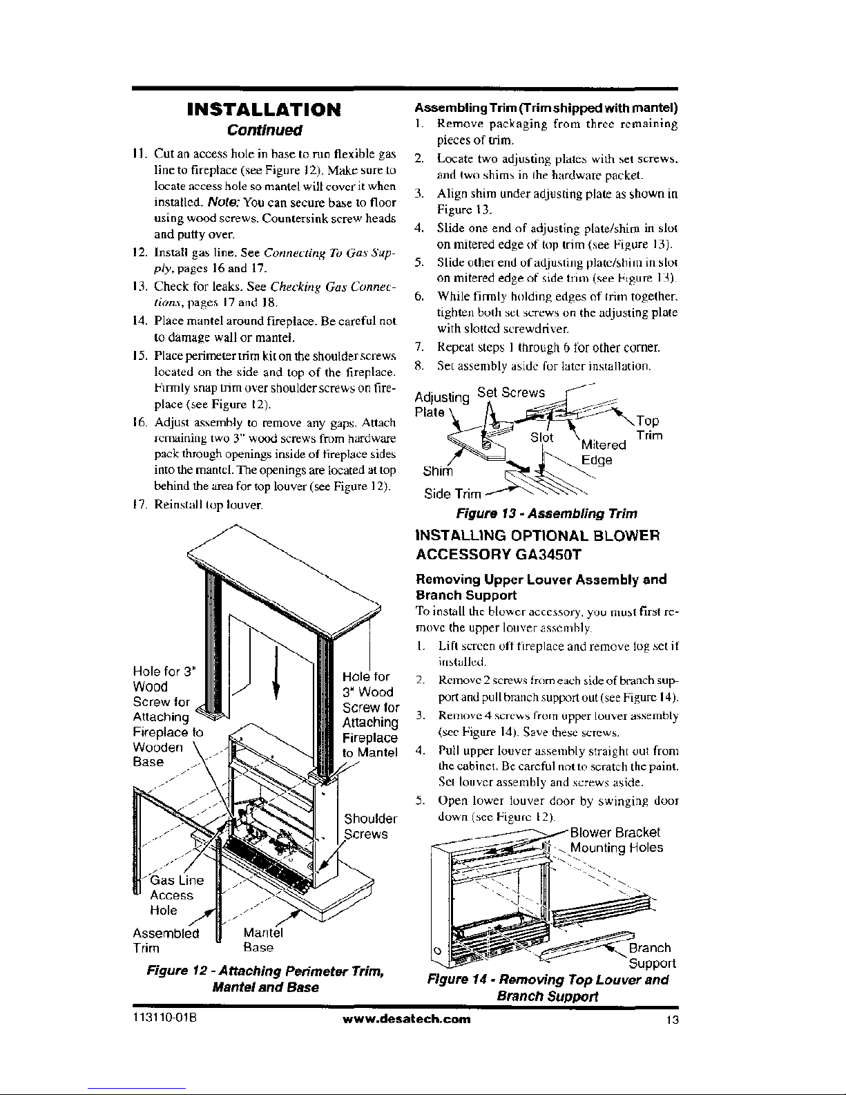
I. Unscrew four screws that attach top louver to
fireplace. Remove louver from fireplace and
set aside (see Figure
I
I).
2. Place base assembly next to wall at installa-
tion location.
I Place fireplace on wood base (see Figure 12.
page 13).
4.
Place mantel around fireplace on base (see
Figure 12, page 13).
5.
Assemble perimeter trim kit See
Assembling
Perimeter Trim,
page 13.
6.
Firmly snap
peritsse(et tutu
kit
on shoulder
screws. Shoulder screws are located on fire-
place cabinet (see Figure 12, page 13).
7.
Align perimeter trim kit for flush fit around
opening.
S. Center mantel left to right on base making
Sure
mantel is flush against wall.
9.
Use two 3" wood screws provided and attach
base of fireplace to wooden mantel base (see
Figure 12, page 13).
10.
Remove perimeter who kit and mantel. Be
careful not to damage wall or mantel.
Side of
Firebox
Figure 10 - Minimum Mantel Clearances
for Built-In Installation
Upper
Louver
Assembly
Figure 11 - Removing Top Louver
12
www.desatech.tom
113110-010
INSTALLATION
Continued
II. Cut an access hole in base to run flexible gas
line to fireplace (see Figure 12). Make sure to
locate access hole so mantel will cover it when
installed.
Note:
You can secure base to floor
using wood screws. Countersink screw heads
and putty oven
12.
Install gas line. See
Connecting To Gas Sup-
ply,
pages 16 and 17.
13.
Check for leaks. See
Checking Gus Connec-
tions,
pages 17 and 18.
14.
Place mantel around fireplace. Be careful not
to damage wall or mantel.
15.
Place perimeter trim kit on the shoulder screws
located on the side and top of the fireplace.
Firmly snap Rim over shoulder screws on fire-
place (see Figure
12).
16.
Adjust assembly to remove any gaps. Attach
remaining two 3" wood screws from hardware
pack through openings inside of fireplace sides
into the mantel. The openings are located at top
behind the area for top louver (see Figure 12),
17.
Reinstall top louver,
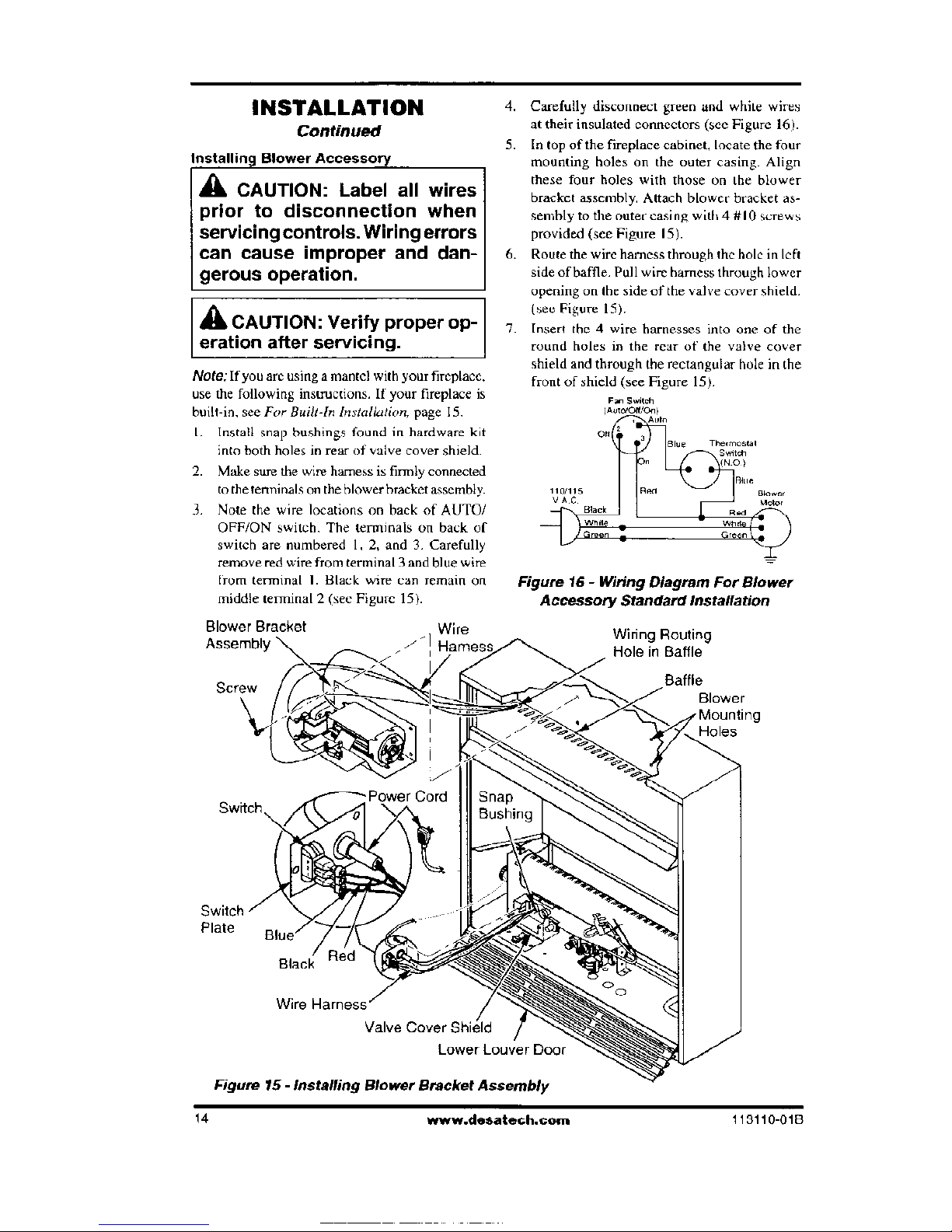
Hole
for
3" Wood
Screw tor
Attaching
Fireplace
to Mantel
Shoulder
Assembling Trim (Trimshipped with mantel)
I.
Remove packaging from three remaining
pieces of trim.
2.
Locate two adjusting plates with set screws.
and two shims in the hardware packet.
3.
Align shim under adjusting plate as shown in
Figure 13.
4.
Slide one end of adjusting plate/shim in slot
on mitered edge of top trim (see Figure 13).
5.
Slide other end of adjusting plate/shim in slot
on mitered edge of side trim (see Figure 13).
6.
While firmly holding edges of (Pm together.
tighten both set screws on the adjusting plate
with slotted screwdriver.
7.
Repeat steps
1
through 6 for other
corner.
8.
Set assembly aside for later installation.
-
Adjusting Set Screws
Plate ,‘‘k4IF
-
N.Top
Slot \
Trim
Mitered
JJ'
Edge
Shim
Side Trim
Figure
13-
Assembling Trim
INSTALLING OPTIONAL BLOWER
ACCESSORY G43450T
Removing Upper Louver Assembly and
Branch Support
To install the blower accessory, you must first re-
move the upper louver assembly.
I. Lift screen off fireplace and remove log set if
installed.
2.
Remove 2 screws from each side of branch sup-
port and pull branch support out (see Figure 14).
3.
Remove 4 scurws from upper- louver assembly
(see Figure 14). Save these screws.
4.
Pull upper louver assembly straight out from
the cabinet. Be careful not to scratch the paint.
Set louver assembly and screws aside.
5.
Open lower louver door by swinging door
down (see Figure 12).
Blower Bracket
Mounting Holes
Assembled
Trim
Figure 12- Attaching Perimeter Trim,
Figure 14- Removing Top Louver and
Mantel and Base
Branch Support
113110-01B
www.desatech.com
13
INSTALLATION
Continued
Installing Blower Accessory
A
CAUTION: Label all wires
prior to disconnection when
servicing controls. Wiring errors
can cause improper and dan-
gerous operation.
A
CAUTION: Verify proper op-
eration after servicing.
Note:
If
you arc using a mantel with your fireplace,
use the following instructions. If your fireplace is
built-in,
see For Built-In Installation,
page 15.
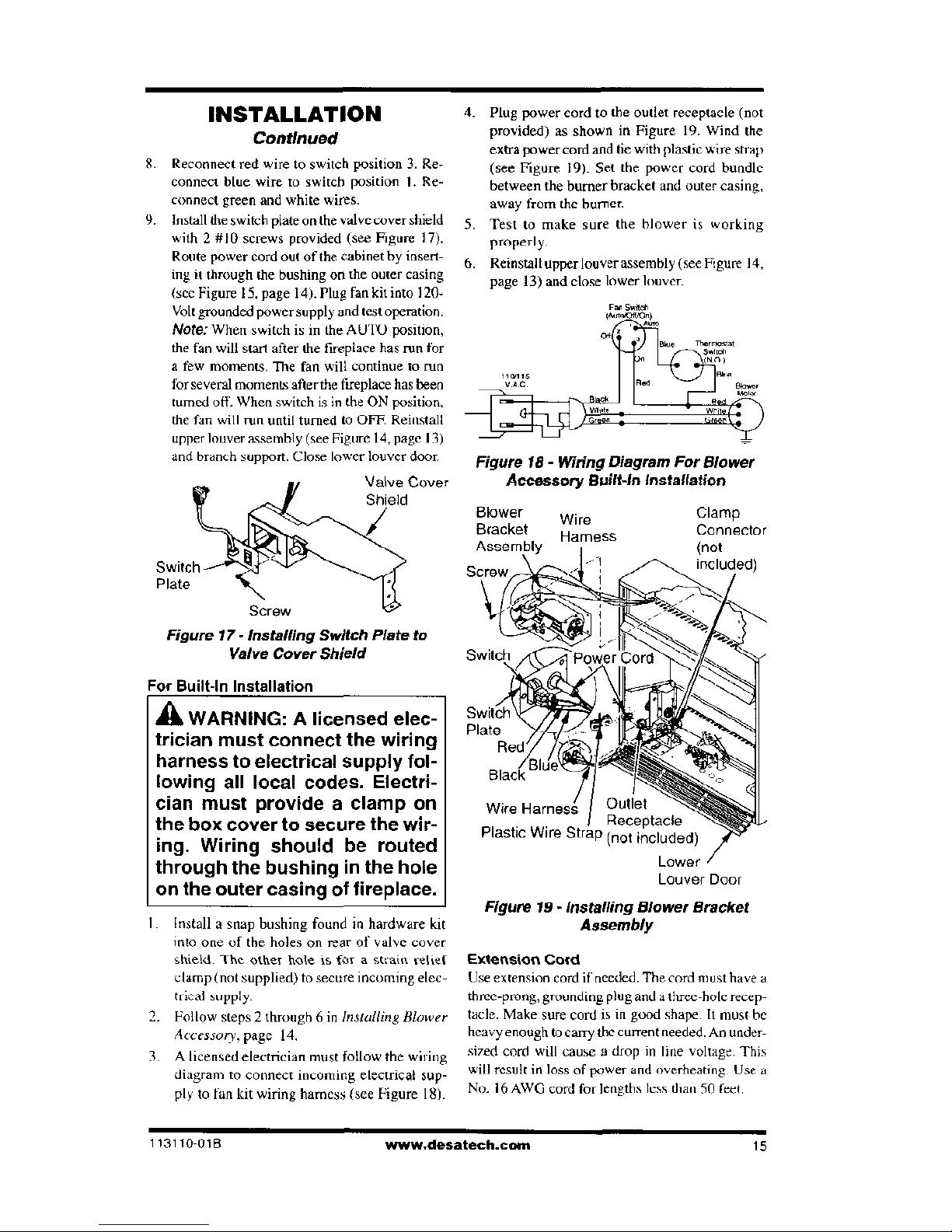
I. Install snap bushings found in hardware kit
into both
holes in rear of valve cover shield.
2.
Make sure the wire harness is firmly connected
to the tenninals on the blower bracket assembly.
3.
Note the wire locations on back of AUTO/
OFF/ON switch. The terminals on back of
switch are numbered I, 2, and 3. Carefully
remove red wire from terminal 3 and blue
wire
(rum terminal
I. Black
wire can remain
on
middle terminal 2 (see Figure 15).
Blower Bracket
Wire
Assembly \
-
7
Harnes:
Screw
4.
Carefully disconnect green and white wires
at their insulated connectors (see Figure
16).
5.
In top of the fireplace cabinet, locate the four
mounting holes on the outer casing. Align
these four holes with those on the blower
bracket assembly. Attach blower bracket as-
sembly to the outer casing with 4 #10 screws
provided (see Figure 15).
6.
Route the wire harness through the hole in left
side of baffle. Pull wire harness through lower
opening on the side of the valve cover shield.
(see Figure 15).
7.
Insert the 4 wire harnesses into one of the
round holes in the
rear of the valve cover
shield and through the rectangular hole in the
front of shield (see Figure 15).
Figure
16- Wiring Diagram For Blower
Accessory Standard Installation
Wiring Routing
Hole in Baffle
Blower
Holes
Cord Snap
a
Bushing
Switch
Plate
Wire
Valve Cover Shield
Lower Louver Door
Figure 75 - Installing Blower Bracket Assembly
14
www.desatech.com
113110-01B
INSTALLATION
Continued
. Reconnect red wire to switch position 3. Re-
connect blue wire to switch position 1. Re-
connect green and white wires.
. Install the switch plate on the valve cover shield
with 2 #I0 screws provided (see Figure 17).
Route power cord out of the cabinet by insert-
ing it through the bushing on the outer casing
(Sec Figure 15, page 14). Plug fan kit into 120-
Volt grounded power supply and test operation.
Note:
When switch is in the AUTO position,
the fan will start after the fireplace has run for
a few moments. The fan will continue to run
for several moments after the fireplace has been
turned off. When switch is in the ON position,
the fan will run until turned to OFF. Reinstall
upper louver assembly (see Figure 14, page 13)
and branch support. Close lower louver door.
Valve Cover
Shield
r°
41
Switch
Plate
S1/4'4.
0
Screw
Figure 17 - Installing Switch Plate to
Valve Cover Shield
For Built-In Installation
A
WARNING: A
licensed elec-
trician must connect the wiring
harness to electrical supply fol-
lowing all local codes. Electri-
cian must provide a clamp on
the box cover to secure the wir-
ing. Wiring should be routed
through the bushing in the hole
on the outer casing of fireplace.
Install a snap bushing found in hardware kit
into one of the holes on rear of valve cover
shield. The other hole is for a strain relief
clamp (not supplied) to secure incoming elec-
ideal supply.
Follow steps 2 through 6 in
Installing Blower
Accessory.
page 14.
A licensed electrician must follow the wiring
diagram to connect incoming electrical sup-
ply to fan kit wiring harness (see Figure 15).
4.
Plug power cord to the outlet receptacle (not
provided) as shown in Figure 19. Wind the
extra power cord and tie with plastic wire strap
(see Figure 19). Set the power cord bundle
between the burner bracket and outer casing,
away from the burner.
5.
Test to make sure the blower is working
properly.
6.
Reinstall upper louver assembly (see Figure 14,
page 13) and close lower louver.
Fan swirl,
ea}
Elive
Therrm,ty
l
ellen
ems
niack
11111/7
v Aa
MVO
permiew•
Figure 18- Wiring Diagram For Blower
Accessory Built-In Installation
Blower
Wire
Clamp
Bracket
Hamess
Connector
-
Plate
Wire Harness
I
Outlet
I Receptacle
Plastic Wire Strap (not included)
Lower
77
Louver Door
Figure 19 - Installing Blower Bracket
Assembly
Extension
Cord
Use extension cord if needed. The cord must have a
thme-prong, grounding plug and a three-hole recep-
tacle. Make sure cord is in good shape. It must be
heavy enough to carry the current needed. An under-
sized cord will cause a drop in line voltage. This
will result in loss of power and overheating. Use a
No. 16 AWG cord for lengths less than 50 feet
113110
-
018
www.clesatech.com
15
INSTALLATION
Continued
CONNECTING TO GAS SUPPLY
A
WARNING: This appliance re-
quires a 450 male flare fitting 5/8"-
18 UNF (Unified National Fine
Thread) inlet connection and the
flexible gas line provided.
A
WARNING: A qualified ser-
vice person must connect fire-
place to gas supply. Follow all
local codes.
A
WARNING: Never connect
natural gas fireplace to private
(non-utility) gas wells. This gas
is commonly known as well-
head gas.
IMPORTANT
For natural gas. check gas line pres-
sure before connecting fireplace to gas line_ Gas
line pressure must be no greater than 14 inches of
water_ If gas line pressure is higher, heater regula-
tor damage could occur.
A
CAUTION: Never connect pro-
pane/LP fireplace directly to the
propane/LP supply. This fireplace
requires an external regulator (not
supplied). Install the external
regulator between the fireplace
and propane/LP supply.
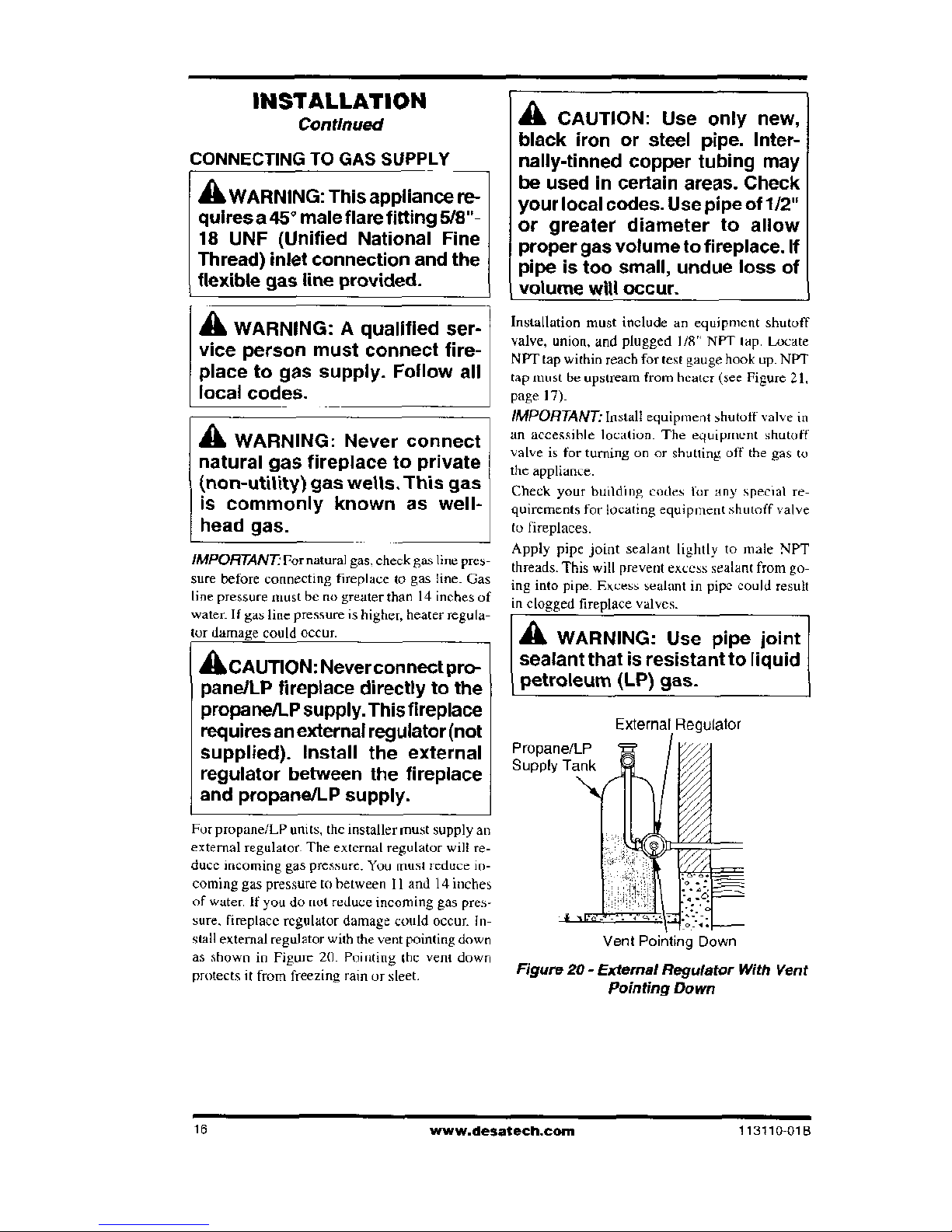
For propane/LP units, thc installer must supply an
extemal regulator. The external regulator will re-
duce incoming gas pressure. You must reduce in-
coming gas pressure to between 11 and 14 inches
of water. If you do not reduce Incoming gas pres-
sure. fireplace regulator damage could occur. In-
stall external regulator with the vent pointing down
as shown in Figure 20. Pointing the vent down
protects it from freezing ram or sleet.
A
CAUTION: Use only new,
black iron or steel pipe. Inter-
nally-tinned copper tubing may
be used in certain areas. Check
your local codes. Use pipe of
1/2"
or greater diameter to allow
proper gas volume to fireplace. If
pipe is too small, undue loss of
volume will occur.
Installation must include an equipment shutoff
valve, union, and plugged 1/8" NPT lap. Locate
NPT tap within reach for test gauge hook up. NPT
tap must be upstream from heater (see Figure 21,
Page 17)-
IMPORTANT:
Install equipment shutoff valve in
an accessible location. The equipment shutoff
valve is for turning on or shutting off the gas to
the appliance.
Check your building codes for any special re-
quirements for locating equipment shutoff valve
to fireplaces.
Apply pipe joint sealant lightly to male NPT
threads. This will prevent excess sealant from go-
ing into pipe. Excess sealant in pipe could result
in clogged fireplace valves.
A
WARNING: Use pipe joint
sealant that is resistant to liquid
petroleum (LP) gas.
External .Regulator
Propane/LP
Supply Tank
Vent Pointing] Down
Figure 20- External Regulator With Vent
Pointing Down
16
www.desatech.com
113110 01B
INSTALLATION
Continued
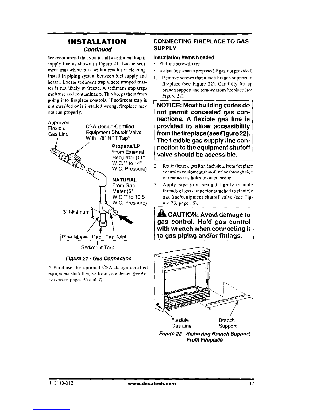
We recommend that you install a sediment trap in
supply line as shown in Figure 21, Locate sedi-
ment trap where it is within reach for cleaning.
Install in piping system between fuel supply and
heater. Locate sediment trap where trapped mat-
ter is not likely to freeze. A sediment trap traps
moisture and contaminants. This keeps them from
going into fireplace controls. If sediment trap is
no installed or is installed wrong, fireplace may
not run properly.
Approved
Flexible
GSA Dosign-Certified
Gas Line
Equipment Shutoff Valve
With 1/8" NPT Tap*
RropaneILR
tfr.
From External
weeib%
Regulator (11"
tek
WC.** to 14"
W.C. Pressure)
NATURAL
From Gas
I
Meter (5"
W.C.“ to 10.5"
e
h.
W.C. Pressure)
3" Minimum Mkt
I
Pipe
Nipple Cap Tee Joint
Sediment Trap
Figure 21 - Gas Connection
* Purchase the optional CSA design-certified
equipment shutoff valve from your dealer. See Ar-
creme/es.
pages 36 and 37.
CONNECTING FIREPLACE TO GAS
SUPPLY
Installation Items Needed
•
Phillips screwdriver
•
sealant (resistant to propane/LP gas, not provided)
I. Remove screws that attach branch support to
fireplace (see Figure 22). Carefully lift up
branch support and remove from fireplace (see
Figure 22).
NOTICE: Most building codes do
not permit concealed gas con-
nections. A flexible gas line is
provided to allow accessibility
from thefireplace (see Figure 22).
The flexible gas supply line con-
nection to the equipment shutoff
valve should be accessible.
2.
Route flexible gas line, included, trom fireplace
control to equipment shutoff valve through side
or rear access holes in outer casing,
3.
Apply pipe joint sealant lightly to male
threads of gas
Connector
attached to flexible
gas line/equipment shutoff valve (see Fig-
III
e,
23, page
18).
A
CAUTION: Avoid damage to
gas control. Hold gas control
with wrench when connecting it
to gas piping andfor fittings.
Figure 22- Removing Branch Support
From Fireplace
113110-018
www.desatech.com
17
INSTALLATION
Continued
4.
Check all gas connections for leaks.
See
Checking Gas Connections.
5.
Replace branch support back into fireplace.
Feed flexible gas line into fireplace base area
while replacing branch support. Make sure the
entire flexible gas line is in fireplace base area.
Reattach branch support to fireplace with
screws removed in step 1, page 17.
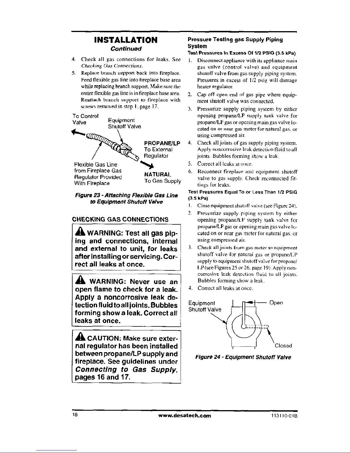
To Control
Valve
Equipment
Shutoff Valve
i
r
RIMIft
PROPANE/LP
fee
tb%
To External
Regulator
Flexible Gas Line
•
%,,A
from Fireplace Gas
Regulator Provided
NATURAL
With Fireplace
To Gas Supply
Figure 23- Attaching Flexible Gas Line
to Equipment Shutoff Valve
CHECKING GAS CONNECTIONS
A
WARNING: Test all gas pip-
ing and connections, internal
and external to unit, for leaks
after Installing or servicing. Cor-
rect all leaks at once.
a
WARNING: Never use an
open flame to check for a leak.
Apply a noncorrosive leak de-
tection fluid to all joints. Bubbles
forming show a leak. Correct all
leaks at once.
A
CAUTION: Make sure exter-
nal regulator has been installed
between propane/LP supply and
fireplace. See guidelines under
Connecting to Gas Supply,
pages 16 and 17.
Pressure Testing gas Supply Piping
System
Test Pressures in Excess 01112 PS1G (3.5 kPa)
I. Disconnect appliance with its appliance main
gas valve (control valve) and equipment
shutoff valve from gas supply piping system.
Pressures in excess of 1/2 psig will damage
heater regulator.
2.
Cap off open end of gas pipe where equip-
ment shutoff valve was connected.
3.
Pressurize supply piping system by either
opening propane/LP supply tank valve for
propane/LP gas or opening main gas valve lo-
cated on or near gas meter for natural gas, or
using compressed air.
4.
Check all joints of gas supply piping system.
Apply noncorrosive leak detection fluid to all
joints. Bubbles forming show a leak.
5.
Correct all leaks at once.
6.
Reconnect fireplace and equipment shutoff
valve to gas supply. Check reconnected fit-
tings for leaks.
Test Pressures Equal To or Less Than 1/2 PS1G
(33 kPa)
I. Close equipment shutoff valve (see Figure 24).
Pressurize supply piping system by either
opening propane/LP supply tank valve for
propane/LP gas or opening main gas valve lo-
cated on or near gas meter for natural gas, or
using compressed air.
3.
Check all joints from gas meter to equipment
shutoff valve for natural gas or propane/LP
supply to equipment shutoff valve for propane/
I,P(sce Figures 25 or 26. page 19). Apply non-
corrosive leak deteelion fluid to all joints.
Bubbles forming show a leak.
4.
Correct all leaks at once.
Equipment
us
Open
Shutoff Valve
-\\
Closed
Figure 24- Equipment Shutoff Valve
18
www.desateeh.com
113110
-
010
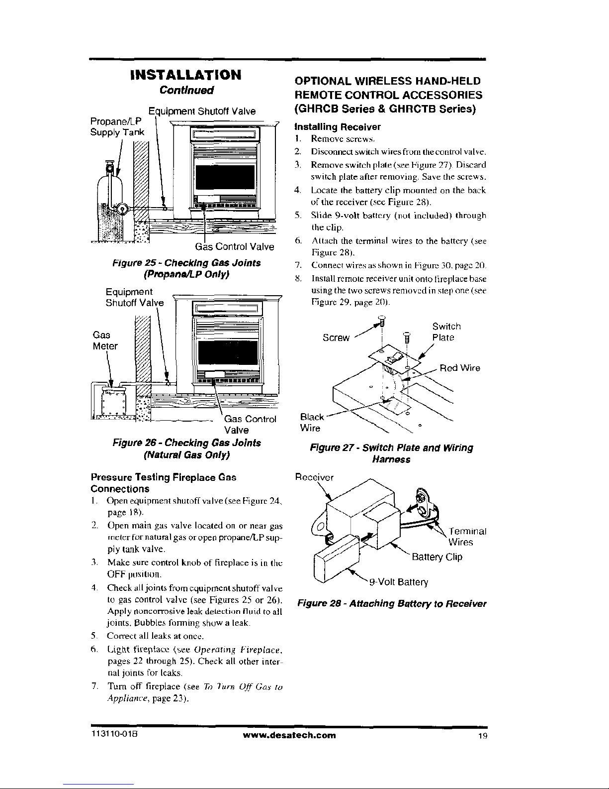
Shutoff Valve
Propane/LP
Supply Tank
Gas Control Valve
Figure 25- Checking Gas Joints
(Propane/I9
Only)
INSTALLATION
OPTIONAL WIRELESS HAND-HELD
Continued
EMLICITC
relltil"Call
A
rreocnolcc
Equipment
Shutoff Val
• —an. • .-••-••• • •
.....
(GHRCB Series & GHRCTB Series)
Installing Receiver
I.
Remove screws.
2.
Disconnect switch wires from the control valve.
3.
Remove switch plate (see Figure 27). Discard
switch plate after removing. Save the screws.
4.
Locate the battery clip mounted on the back
of the receiver (sec Figure 28).
5.
Slide 9-volt battery (not included) through
the clip.
6.
Attach the terminal wires to the battery (see
Figure 28).
7.
Connect wires as
shown
in Figure 30. page 20.
S. Install remote receiver unit onto fireplace base
using the two screws removed in step
one
(see
Figure 29. page 20h
Switch
Gas
Screw
Plate
Red Wire
Gas Control
Valve
Figure 26- Checking Gas Joints
(Natural Gas Only)
Pressure Testing Fireplace Gas
Connections
I. Open equipment shutoff valve (see Figure 24,
page IS).
2.
Open main gas valve located on or near gas
meter
for natural gas or open propane/LP sup-
ply tank valve.
3. Make sure control knob of fireplace is in the
OFF position.
4.
Check all joints from equipment shutoff valve
to gas control valve (see Figures 25 or 26).
Apply noncorrosive leak
detection fluid to
all
joints. Bubbles conning show a leak.
5.
Correct all leaks at once.
6.
Light fireplace
(see Operating
Fireplace.
pages 22 through 25). Check all other inter-
nal joints for leaks.
7.
Turn off fireplace (see
Ta ?urn Off Gas la
Appliance,
page 23).
Black'
Wire
-
Figure 27- Switch Plate and Wiring
Harness
Terminal
Battery Clip
9-Volt Battery
Figure 28- Attaching Battery to Receiver
113110
-
018
www.desatech.com
19
INSTALLATION
Continued
A
WARNING: Do not connect
6.
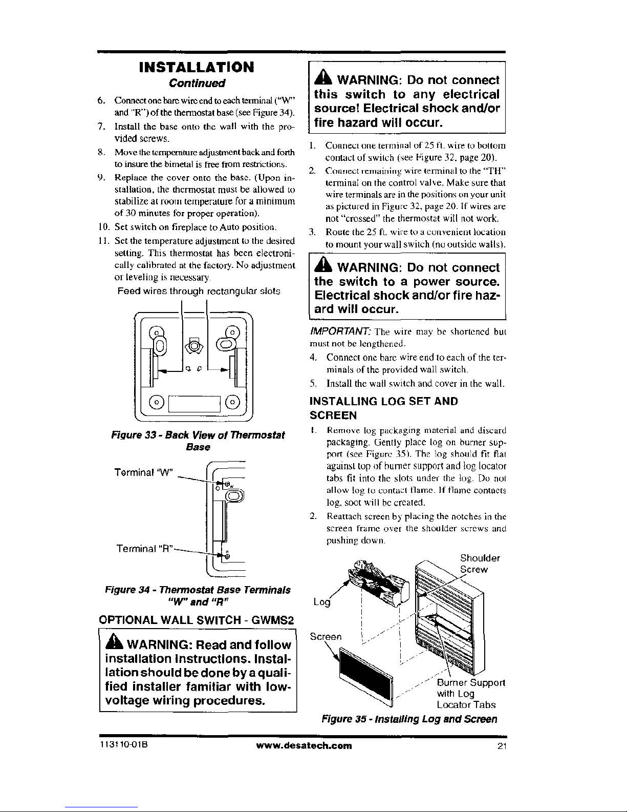
Connect one bare wire end to each terminal ("W"
this switch to any electrical
and "R")of the thermostat base (see Figure 34).
source! Electrical shock and/or
7.
Install the base onto the wall with the pro-
fire hazard will occur.
vidprl errptve
8.
Move the temperature adjustment back and forth
to insure the bimetal is free from restrictions.
9.
Replace the cover onto the base. (Upon in-
stallation, the thermostat most be allowed to
stabilize at 100111 temperature for a minimum
of 30 minutes for proper operation).
10.
Set switch on fireplace to Auto position.
11.
Set the temperature adjustment to the desired
setting. This thermostat has been electroni-
cally calibrated at the factory. NV adjustment
or leveling is necessary.
Feed wires through rectangular slots
Ct
0
0
0
Figure 33- Back View of Thermostat
Base
Terminal 'W
Cr
Terminal "R"
t.
L
Figure 34- Thermostat Base Terminals
"WV" and
"R"
OPTIONAL WALL SWITCH - GWMS2
A
WARNING: Read and follow
installation Instructions. Instal-
lation should be done by a quali-
fied installer familiar with low-
voltage wiring procedures.
I. Connect one terminal of
25
ft. wire to bottom
contact of switch (see Figure 32. page 20).
2.
Connect remaining wire terminal to the "TIT'
terminal on the control valve. Make sure that
wire terminals are in the positions on your unit
as pictured in Figure 32, page 20.1f wires are
not "crossed" the thermostat will not work.
3.
Route the
25
ft. wire to a convenient location
to mount your wall switch (no outside walls).
A
WARNING: Do not connect
the switch to a power source.
Electrical shock
and/or fire
haz-
ard will occur.
IMPORTANT'
The wire may be shortened but
must not be lengthened.
4.
Connect one bare wire end to each of the ter-
minals of the provided wall switch.
5.
Install the wall switch and cover in the wall.
INSTALLING LOG SET AND
SCREEN
I. Remove log packaging material and discard
packaging. Gently place log on burner sup-
port (see Figure 35). The log should fit flat
against top of burner support and log locator
tabs fit into the slots under the log. Do not
allow log to contact flame. If flame contacts
log, soot will he created.
2. Reattach screen by placing the notches in the
screen frame over the shoulder screws and
pushing down.
Shoulder
Screen
Burner Support
-
with Log
Locator Tabs
Figure 35 - Installing Log and Screen
113110-01B
www.clesatech.com
21
NOTICE: During initial operation
of newfireplace, burning logs will
give off a paper-burning smell.
Open window to vent smelt This
will only last a
few
hours.
1.
STOP! Read the safety information in col-
umn 1.
2.
Make sure equipment shutoff valve is fully
open.
3.
Set switch in the OFF position.
A WARNING: Burner will come
on automatically within one
minute when the selector switch
is in the ON position after the
pilot is lit.
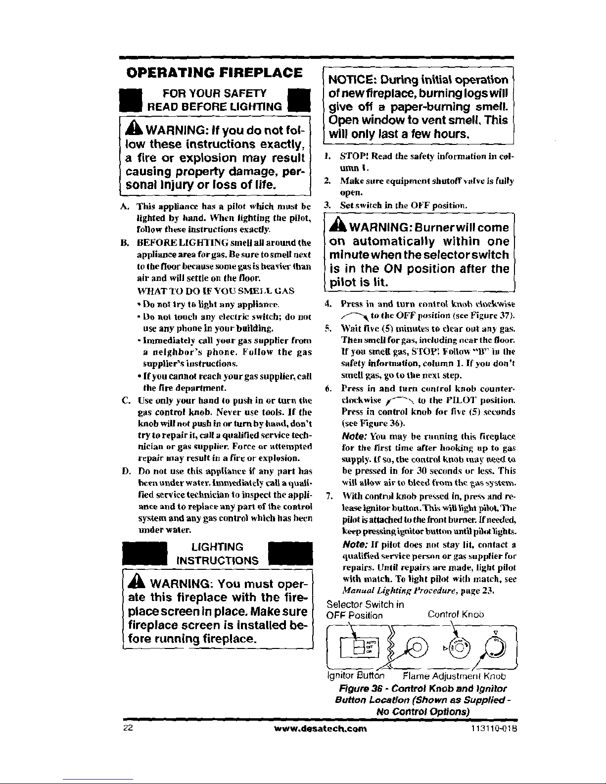
4.
Press in And turn control knob elockwise
to the OFF position (see Figure 37).
5.
Wait live (5) minutes to clear out any gas.
Then smell for gas, including near the floor.
lf you smell gas, STOP: Follow "II" in the
safety information, column 1. If you don't
smell gas, go to the next step.
6.
Press in and turn control knob counter-
clockwise ir 'Th., to the PILOT position.
Press in control knob for five (5) seconds
(see Figure 36).
Note:
You may be running this fireplace
for the first time after hooking up to gas
supply. if so, the control knob may need to
be pressed in for 30 seconds or less. This
will allow air to bleed from the gas system.
7.
With control knob pressed in, press and re-
lease ignitor button.This will light pilot.The
pilot is attached to the front burner. If needed,
keep pressingignitor button until pilotlights.
LIGHTING
Note:
If pilot does not stay lit, contact a
INSTRUCTIONS
qualified service person or gas supplier for
repairs. Until repairs are made, light pilot
A
WARNING: You must oper
-
with match. To light pilot with match,
see
Manual Lighting Procedure,
page 23.
ate this fireplace with the fire-
Selector Switch in
place screen in place. Make sure
OFF
Position
Control Knob
fireplace screen is Installed be
t
fore running fireplace.
Ignitor Button
Flame Adjustment Knob
Figure 36- Control Knob and ignitor
Button Location (Shown as Supplied -
Alo Control Options)
22
www.desatech.eam
113110-01B
OPERATING FIREPLACE
FOR YOUR SAFETY III
READ BEFORE LIGHTING
A
WARNING: If you do not fol-
low these instructions exactly,
a fire or explosion may result
causing property damage, per-
sonal Injury or loss of life.
A.
This appliance has a pilot which most be
lighted by hand. When lighting the pilot,
follow these instructions exactly.
B.
BEFORE LIGHTING smell all around the
appliance area for gas. Be sure to smell next
to the floor because some gas is heavier than
air and will settle on the floor.
WHAT TO DO IF YOU SMELL GAS
•
Do not try to light any appliance.
•
Do not touch any electric switch; do not
use any phone in your building.
•
Immediately call your gas supplier from
a neighbor's phone. Follow the gas
supplier's instructions.
•
If you cannot reach your gas supplier, call
the fire department.
C.
Use only your hand to push in or turn the
gas control knob. Never use tools. If the
knob will not push in or turn by hand, don't
try to repair it, call a qualified service tech-
nician or gas supplier. Force or attempted
repair may result in a tire or explosion.
D.
Do not use this appliance if any part has
been under water. Immediately call a quali-
fied service technician to inspect the appli-
ance and to replace any part of the control
system and any gas control which has been
under water.
OPERATING FIREPLACE
Continued
8.
Keep control knob pressed in for 30 sec-
onds after lighting pilot. After 30 seconds,
release control knob.
• If control knob does not pop out when re-
leased, contact a qualified service person
or gas supplier for repairs.
Note:
If pilot goes out, repeat steps 4
through 8.
9.
Slightly push in and turn control knob coun-
terclockwise "Cs to the ON position.
10.
Wait one minute and switch selector switch
to the ON position to light burner.
II. Set name adjustment knob to any level be-
tween HI and LO.
A
CAUTION: Do not try to ad-
just heating levels by using the
equipment shutoff valve.
A
WARNING: Make sure the
selector switch is in the OFF
position when you are away from
home for long periods of time.
Fireplace will come on automati-
cally with selector switch in the
ON position.
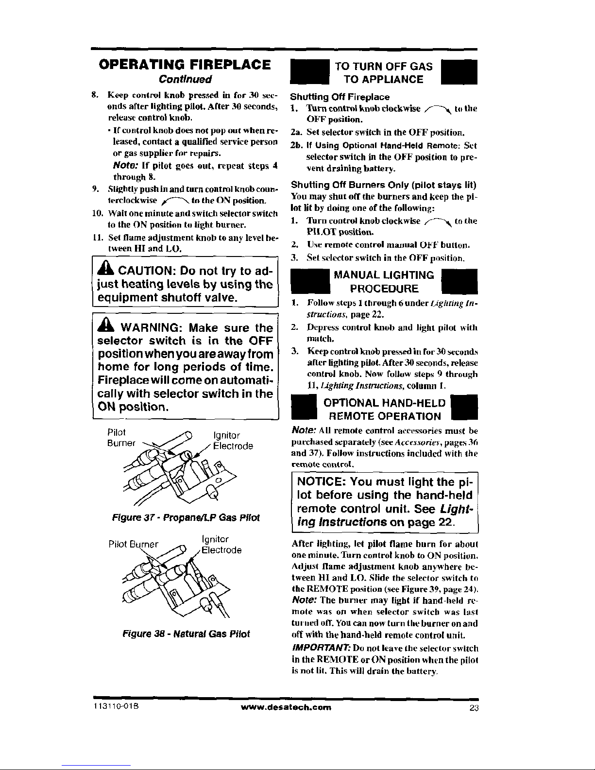
Pilot
i
Ignitor
Burner
Electrode
APT'S°
••\\
Figure 37- Propane/LP Gas
Pilot
Pilot Burner
Ireicto
trrode
41 soh:a tfr
e
r
r\
Figure 38 - Natural Gas Pilot
TO TURN OFF GAS
TO APPLIANCE
Shutting Off Fireplace
1. Turn
control knob clockwise ."-
-Th1/4
to the
OFF position.
2a.
Set selector switch in the OFF position.
2b.
If Using
Optional Hand-Held Remote: Set
selector switch in the OFF position to pre-
sent draining battery.
Shutting
Off Burners Only (pilot stays
lit)
You may shut off the burners and keep the pi-
lot lit by doing one of the following:
I. Turn control knob clockwise
to the
PILOT position.
2.
Use remote control manual OFF button.
3. Set selector switch in the OFF position.
MANUAL LIGHTING
PROCEDURE
1.
Follow steps 1 through 6 under
bighting In-
structions,
page
22.
2.
Depress control knob and light pilot with
match.
3.
Keep control knob pressed in for 30 seconds
after lighting pilot. After 30 seconds, release
control knob. Now follow steps 9 through
11,
Lighting Instructions,
column
I.
II
OPTIONAL HAND-HELD II
REMOTE OPERATION
Note:
All remote control accessories must be
purchased separately (see
Accessories,
pages 36
and 37). Follow instructions included with the
remote control.
NOTICE: You must light the pi-
lot before using the hand-held
remote control unit. See
Light-
ing Instructions
on page 22.
—
After lighting, let pilot flame burn for about
one minute. Turn control knob to ON position.
Adjust flame adjustment knob anywhere be-
tween HI and LO. Slide the selector switch to
the REMOTE position (see Figure 39, page
24).
Note:
The burner may light if hand-held re-
mote was on when selector switch was last
turned off. You can now turn the burner on and
off with the hand-held remote control unit.
IMPORTANT:
Do not leave the selector switch
in the REMOTE or ON position when the pilot
is not lit. This will drain the battery.
113110-018
www.desatech.com
23
 Loading...