

Page 1

100 Corporate Drive Mahwah, NJ 07430
Service Bulletin
No. : OST-C1528
Date: July 1, 2009
_____________________________________________________________
Model: POA-A1HDCI
Subject: Change the voltage of power supply for OP amplifier.
Countermeasure is applicable only upon claim from the customer.
Symptom: The unit goes into protection mode.
Solution:
supply, but few OP amplifiers was damaged by over "+15/-15 volts".
COUNTERMEASURE: We pulled down the voltage of the power supply from
"+18/-18 volts" to "+15/-15 volts".
1) 1U-3798-1 AMP UNIT:
a) IC102, IC103: SA5532ADR (00D2623555901)→NJM5532M-D (TE-
1)(00D2630898907)
b) ZD101, ZD102: HZS22-1 (00D2760480900)→HZS20-1TD (00D2760479908)
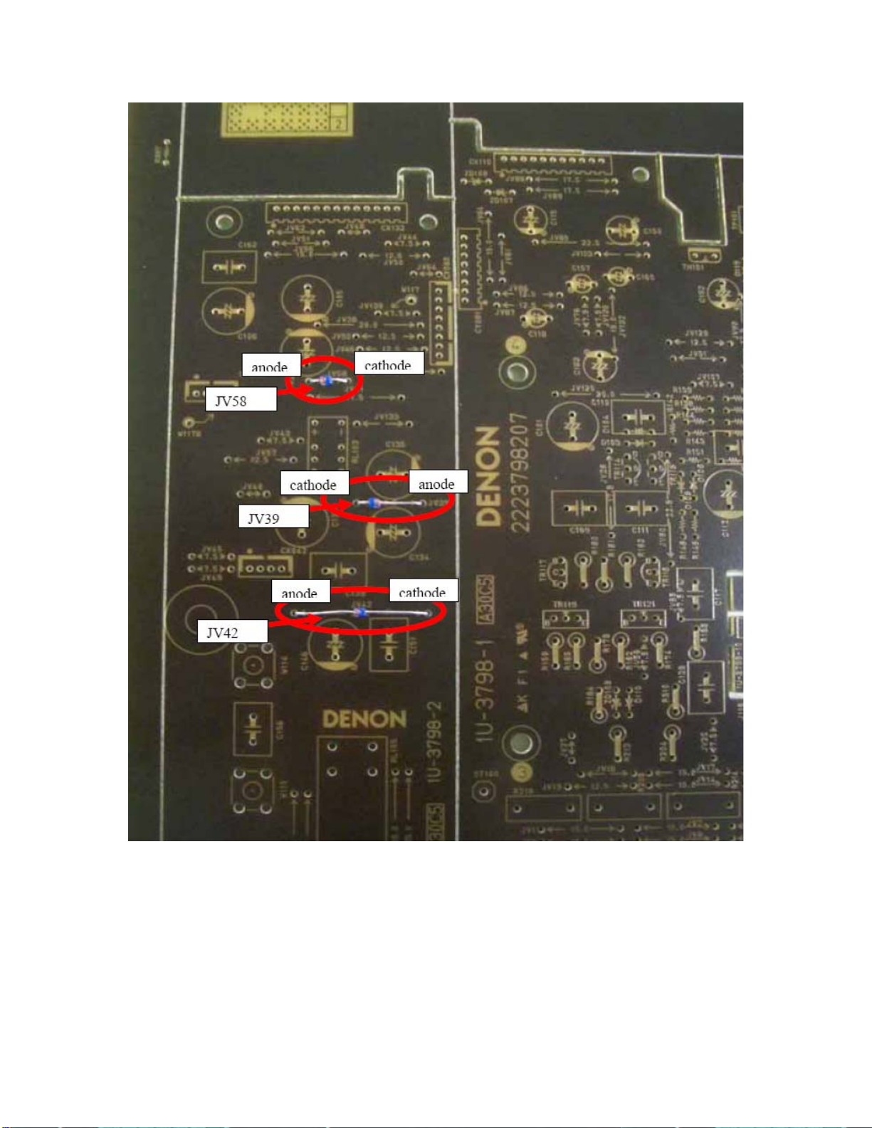
2) 1U-3798-2 INPUT UNIT: a) JV39, JV42, JV58: Jumper Wire→HZS3B-2TD
(00D2760453911)
See the following picture for details.
Generally OP amplifier is not defective at "+18/-18 volts" power
______________________________________________________________________________________
The information contained in this document is intended for the exclusive use by DENON Authorized Service Centers and their
employees. This document may contain information that is privileged, confidential and may be protected from disclosure under
applicable laws and terms of the DENON Service Agreement. Any distribution, disclosure, dissemination or copying of this
document and the information it contains is prohibited. No responsibility will be accepted by DENON for any damage, injury or loss
resulting from the misuse of the information contained in this document.
CONFIDENTIALITY NOTICE:
Page 2
______________________________________________________________________________________
CONFIDENTIALITY NOTICE:
The information contained in this document is intended for the exclusive use by DENON Authorized Service Centers and their
employees. This document may contain information that is privileged, confidential and may be protected from disclosure under
applicable laws and terms of the DENON Service Agreement. Any distribution, disclosure, dissemination or copying of this
document and the information it contains is prohibited. No responsibility will be accepted by DENON for any damage, injury or loss
resulting from the misuse of the information contained in this document.
Page 3
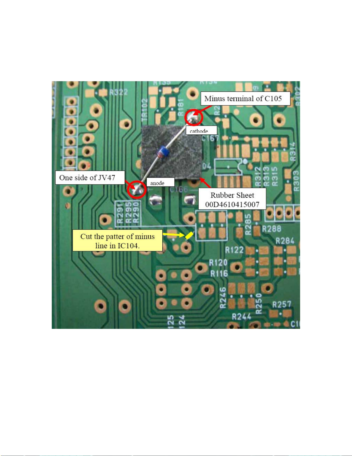
b) Cut the pattern of minus line in IC104.
c) Solder the diode HZS3B-2 to the PCB with a RUBBER SHEET under the
component (on PC board).
d) IC101, IC104: SA5532ADR (00D2623555901)→SE5532AD8R2G
(232810020503S)
3) 1U-3797-3/4/5/6/7 CONNECT UNIT:
a) IC511, IC512, IC513, IC514, IC515: SA5532ADR
(00D2623555901)→SE5532AD8R2G (232810020503S)
______________________________________________________________________________________
CONFIDENTIALITY NOTICE:
The information contained in this document is intended for the exclusive use by DENON Authorized Service Centers and their
employees. This document may contain information that is privileged, confidential and may be protected from disclosure under
applicable laws and terms of the DENON Service Agreement. Any distribution, disclosure, dissemination or copying of this
document and the information it contains is prohibited. No responsibility will be accepted by DENON for any damage, injury or loss
resulting from the misuse of the information contained in this document.
Page 4

b) Cut the pattern of the power supply line for OP amplifier.
______________________________________________________________________________________
CONFIDENTIALITY NOTICE:
The information contained in this document is intended for the exclusive use by DENON Authorized Service Centers and their
employees. This document may contain information that is privileged, confidential and may be protected from disclosure under
applicable laws and terms of the DENON Service Agreement. Any distribution, disclosure, dissemination or copying of this
document and the information it contains is prohibited. No responsibility will be accepted by DENON for any damage, injury or loss
resulting from the misuse of the information contained in this document.
Page 5

______________________________________________________________________________________
CONFIDENTIALITY NOTICE:
The information contained in this document is intended for the exclusive use by DENON Authorized Service Centers and their
employees. This document may contain information that is privileged, confidential and may be protected from disclosure under
applicable laws and terms of the DENON Service Agreement. Any distribution, disclosure, dissemination or copying of this
document and the information it contains is prohibited. No responsibility will be accepted by DENON for any damage, injury or loss
resulting from the misuse of the information contained in this document.
Page 6

c) Attach the RUBBER SHEET and cloth tape on the printing board.
d) Attach the HZS3B-2 (00D2760453911) on the A side of printing board.
______________________________________________________________________________________
CONFIDENTIALITY NOTICE:
The information contained in this document is intended for the exclusive use by DENON Authorized Service Centers and their
employees. This document may contain information that is privileged, confidential and may be protected from disclosure under
applicable laws and terms of the DENON Service Agreement. Any distribution, disclosure, dissemination or copying of this
document and the information it contains is prohibited. No responsibility will be accepted by DENON for any damage, injury or loss
resulting from the misuse of the information contained in this document.
Page 7

Caution!:
1) Do not mistake the direction (position) of the diodes. Please verify proper
positioning BEFORE soldering.
2) Do not use the wrong diodes. (There are 2 types of Diodes used.)
3) Do not cut the wrong patterns. Please check it by (DVM) tester.
Parts:
Ref# Description Part Number
JV39, JV42,
HZS3B-2TD 00D2760453911
JV58
IC101, IC104,
SE5532AD8R2G 232810020503S
IC511, IC512,
IC513, IC514,
IC515
IC102, IC103 NJM5532M-D(TE1) 00D2630898907
ZD101, ZD102 HZS20-1TD 00D2760479908
For HZS3B-2TD RUBBER SHEET 00D4610415007
Serial Number Range:
Please apply the above modification to the production models in the following
serial numbers. (Last 5-digits)
00001 ~ 00221
______________________________________________________________________________________
The information contained in this document is intended for the exclusive use by DENON Authorized Service Centers and their
employees. This document may contain information that is privileged, confidential and may be protected from disclosure under
applicable laws and terms of the DENON Service Agreement. Any distribution, disclosure, dissemination or copying of this
document and the information it contains is prohibited. No responsibility will be accepted by DENON for any damage, injury or loss
resulting from the misuse of the information contained in this document.
CONFIDENTIALITY NOTICE:
 Loading...