

Denon POA-3012CI Service Manual
Ver. 1
SERVICE MANUAL
MODEL JP E3 E2 EK E2A E1C E1K EUT
POA-3012CI
33
STEREO POWER AMPLIFIER
注 意
サービスをおこなう前に、このサービスマニュアル
を必ずお読みください。本機は、火災、感電、けが
などに対する安全性を確保するために、さまざまな
配慮をおこなっており、また法的には「電気用品安
全法」にもとづき、所定の許可を得て製造されてお
ります。従ってサービスをおこなう際は、これらの
安全性が維持されるよう、このサービスマニュアル
に記載されている注意事項を必ずお守りください。
●
For purposes of improvement, specifications and
design are subject to change without notice.
●
Please use this service manual with referring to the
operating instructions without fail.
●
Some illustrations using in this service manual are
slightly different from the actual set.
e
Denon Brand Company, D&M Holdings lnc.
●
本機の仕様は性能改良のため、予告なく変更すること
があります。
●
補修用性能部品の保有期間は、製造打切後 8 年です。
●
修理の際は、必ず取扱説明書を参照の上、作業を行っ
てください。
●
本文中に使用しているイラストは、説明の都合上現物
と多少異なる場合があります。
X0364 V.01 DE/CDM 0803
SAFETY PRECAUTIONS
The following check should be performed for the continued protection of the customer and service technician.
LEAKAGE CURRENT CHECK
Before returning the unit to the customer, make sure you make either (1) a leakage current check or (2) a line to chassis
resistance check. If the leakage current exceeds 0.5 milliamps, or if the resistance from chassis to either side of the
power cord is less than 460 kohms, the unit is defective.
CAUTION
Please heed the points listed below during servicing and inspection.
◎ Heed the cautions!
Spots requiring particular attention when servicing, such
as the cabinet, parts, chassis, etc., have cautions indicated
on labels or seals. Be sure to heed these cautions and the
cautions indicated in the handling instructions.
◎ Caution concerning electric shock!
(1) An AC voltage is impressed on this set, so touching in-
ternal metal parts when the set is energized could
cause electric shock. Take care to avoid electric shock,
by for example using an isolating transformer and
gloves when servicing while the set is energized, unplugging the power cord when replacing parts, etc.
(2)There are high voltage parts inside. Handle with extra
care when the set is energized.
◎ Caution concerning disassembly and
assembly!
Though great care is taken when manufacturing parts from
sheet metal, there may in some rare cases be burrs on the
edges of parts which could cause injury if fingers are
moved across them. Use gloves to protect your hands.
◎ Inspect for safety after servicing!
Check that all screws, parts and wires removed or disconnected for servicing have been put back in their original positions, inspect that no parts around the area that has been
serviced have been negatively affected, conduct an insulation check on the external metal connectors and between
the blades of the power plug, and otherwise check that
safety is ensured.
(Insulation check procedure)
Unplug the power cord from the power outlet, disconnect
the antenna, plugs, etc., and turn the power switch on. Using a 500V insulation resistance tester, check that the insulation resistance between the terminals of the power
plug and the externally exposed metal parts (antenna terminal, headphones terminal, microphone terminal, input
terminal, etc.) is 1MΩ or greater. If it is less, the set must
be inspected and repaired.
CAUTION
Concerning important safety
parts
◎ Only use designated parts!
The set's parts have specific safety properties (fire resistance, voltage resistance, etc.). For replacement parts, be
sure to use parts which have the same properties. In particular, for the important safety parts that are marked z on
wiring diagrams and parts lists, be sure to use the designated parts.
◎ Be sure to mount parts and arrange
the wires as they were originally!
For safety reasons, some parts use tape, tubes or other insulating materials, and some parts are mounted away from
the surface of printed circuit boards. Care is also taken with
the positions of the wires inside and clamps are used to
keep wires away from heating and high voltage parts, so
be sure to set everything back as it was originally.
Many of the electric and structural parts used in the set
have special safety properties. In most cases these properties are difficult to distinguish by sight, and using replacement parts with higher ratings (rated power and
withstand voltage) does not necessarily guarantee that
safety performance will be preserved. Parts with safety
properties are indicated as shown below on the wiring diagrams and parts lists is this service manual. Be sure to replace them with parts with the designated part number.
(1) Schematic diagrams ... Indicated by the z mark.
(2) Parts lists ... Indicated by the z mark.
Using parts other than the designated
parts could result in electric shock, fires or
other dangerous situations.
2
POA-3012CI

注 意
サービス、点検時にはつぎのことにご注意願います。
◎注意事項をお守りください!
サービスのとき特に注意を必要とする個所については
キャビネット、部品、シャーシなどにラベルや捺印で注意
事項を表示しています。これらの注意書きおよび取扱説明
書などの注意事項を必ずお守りください。
◎感電に注意!
(1) このセットは、交流電圧が印加されていますので通電
時に内部金属部に触れると感電することがあります。
従って通電サービス時には、絶縁トランスの使用や手
袋の着用、部品交換には、電源プラグを抜くなどして
感電にご注意ください。
(2) 内部には高電圧の部分がありますので、通電時の取扱
には十分ご注意ください。
◎分解、組み立て作業時のご注意!
板金部品の端面の『バリ』は、部品製造時に充分管理をし
ておりますが、板金端面は鋭利となっている箇所が有りま
すので、部品端面に触れたまま指を動かすとまれに怪我を
する場合がありますので十分注意して作業して下さい。手
の保護のために手袋を着用してください。
◎指定部品の使用!
セットの部品は難燃性や耐電圧など安全上の特性を持っ
たものとなっています。従って交換部品は、使用されてい
たものと同じ特性の部品を使用してください。特に配線
図、部品表にz印で指定されている安全上重要な部品は
必ず指定のものをご使用ください。
◎部品の取付けや配線の引きまわしは、
元どおりに!
安全上、テープやチューブなどの絶縁材料を使用したり、
プリント基板から浮かして取付けた部品があります。また
内部配線は引きまわしやクランパーによって発熱部品や
高圧部品に接近しないように配慮されていますので、これ
らは必ず元どおりにしてください。
◎サービス後は安全点検を!
サービスのために取り外したねじ、部品、配線などが元ど
おりになっているか、またサービスした個所の周辺を劣化
させてしまったところがないかなどを点検し、外部金属端
子部と、電源プラグの刃の間の絶縁チェックをおこなうな
ど、安全性が確保されていることを確認してください。
(絶縁チェックの方法)
電源コンセントから電源プラグを抜き、アンテナやプラグ
などを外し、電源スイッチを入れます。500V 絶縁抵抗計
を用いて、電源プラグのそれぞれの端子と外部露出金属部
[アンテナ端子、ヘッドホン端子、マイク端子、入力端子
など]との間で、絶縁抵抗値が1 MΩ 以上であることを
確認してください。この値以下のときはセットの点検修理
が必要です。
注 意
本機に使用している多くの電気部品、および機構部品は安
全上、特別な特性を持っています。この特性はほとんどの
場合、外観では判別つきにくく、またもとの部品より高い
定格(定格電力、耐圧)を持ったものを使用しても安全性
が維持されるとは、限りません。安全上の特性を持った部
品は、このサービスマニュアルの配線図、部品表につぎの
ように表示していますので必ず指定されている部品番号
のものを使用願います。
(1) 配線図…zマークで表示しています。
(2) 部品表…zマークで表示しています。
安全上重要な部品について
指定された部品と異なるものを使用した場
合には、感電、火災などの危険を生じる恐
れがあります。
3
POA-3012CI
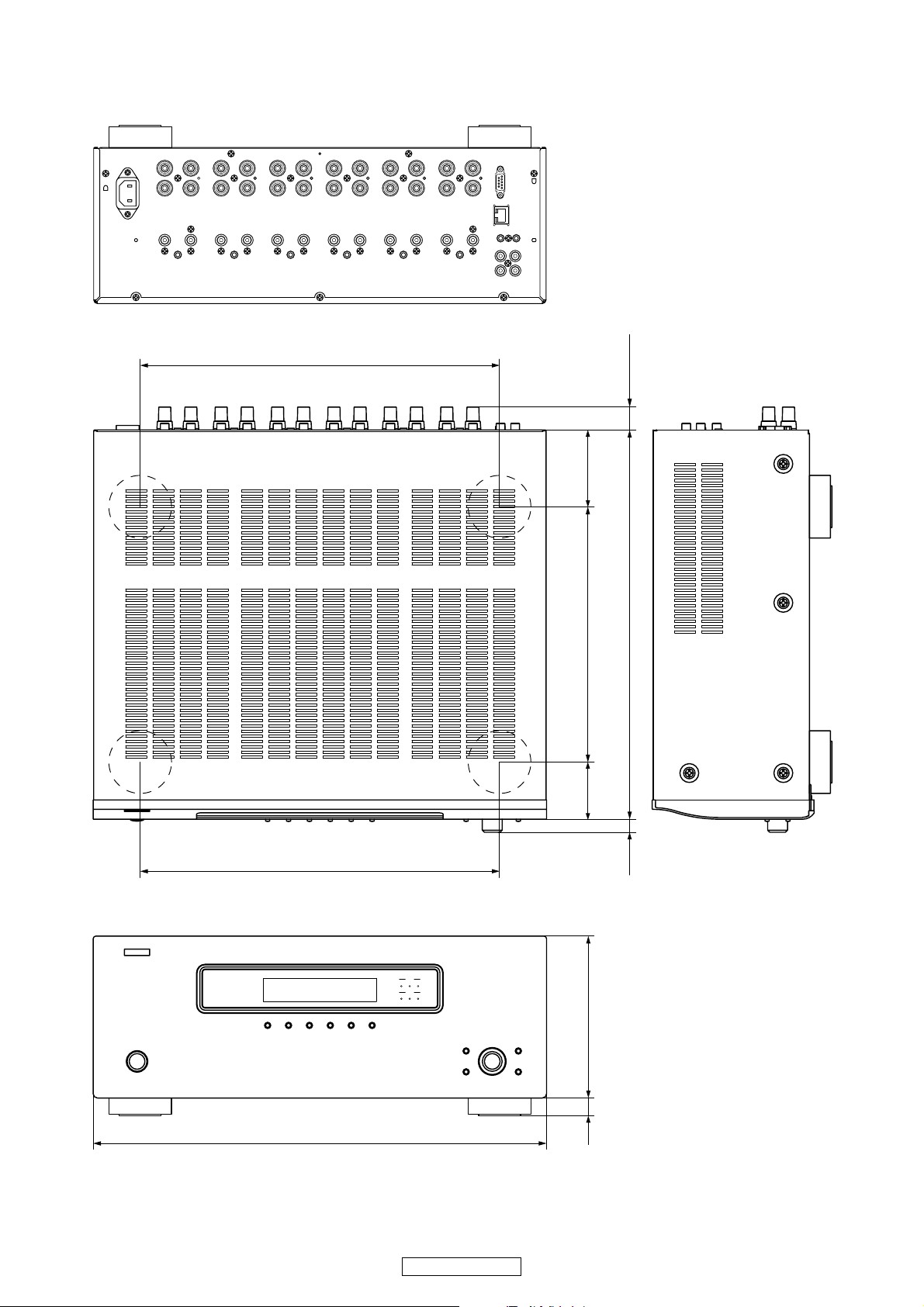
DIMENSION
W434 X H171 X D410
344
25.5 max
73
344
ZONE
123
ZONE
456
372
54.5 244.5
12.5
155
434
16
4
POA-3012CI
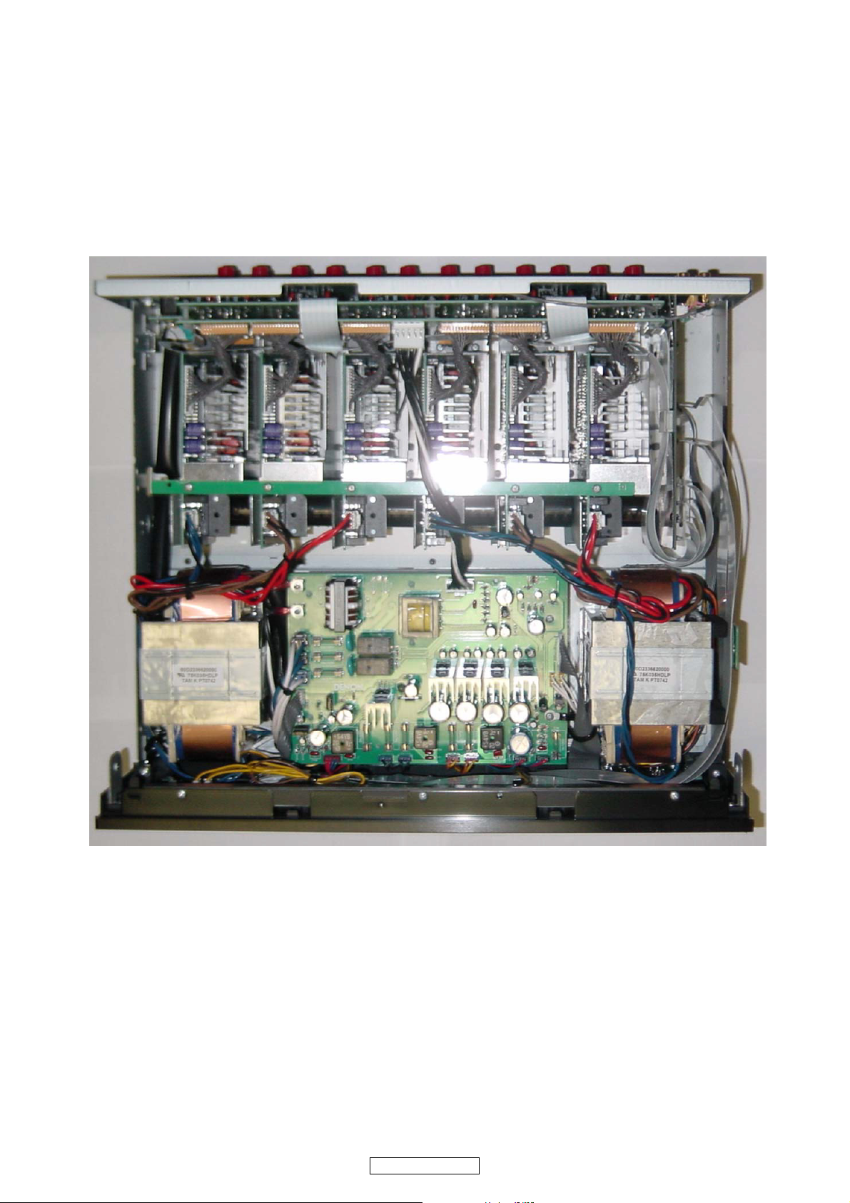
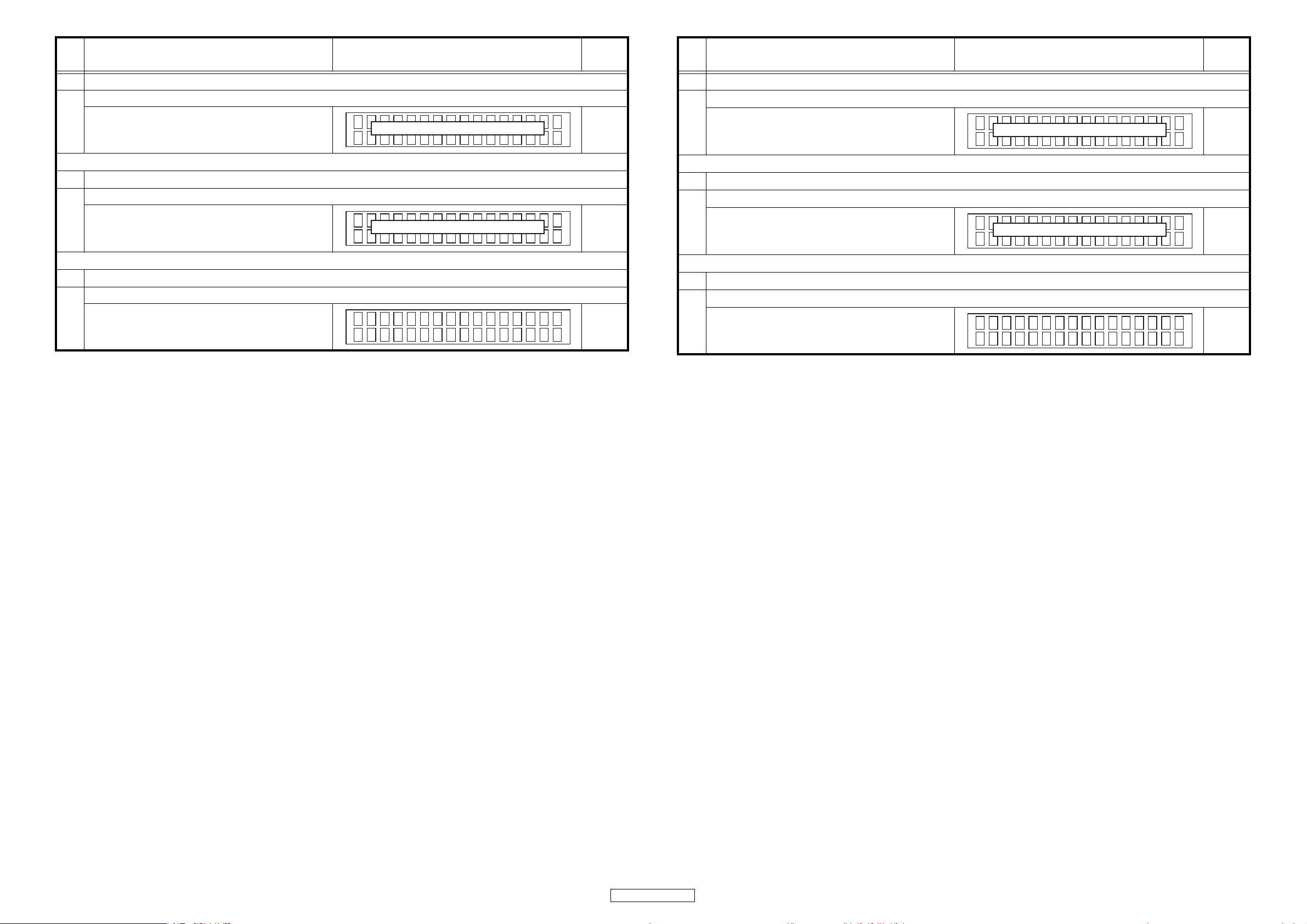
WIRE ARRANGEMENT
If wire bundles are untied or moved to perform adjustment or
parts replacement etc., be sure to rearrange them neatly as
they were originally bundled or placed afterward.
Otherwise, incorrect arrangement can be a cause of noise
generation.
ワイヤー整形図
調整や部品の交換等により、ワイヤー類の結束をはずした
り移動させた場合には、それらの作業が完了した時点でワ
イヤーの整形をおこなってください。正しく整形されてい
ないとノイズ発生の原因となることがあります。
Wire arrangement viewed from the top
上面からみたワイヤー整形
Back Panel side
Front Panel side
5
POA-3012CI

CAUTION IN SERVICING
サービス時の注意事項
Initializing POA-3012CI
S-81/S-81DAB initialization should be performed when the
ucom and peripheral parts of ucom are replaced.
1. Unplug the power cord from the power outlet.
2. Connect the power cord to the power outlet while simultaneously pressing the ZONE 5 and DISPLAY buttons.
3. When all Zone operation mode LED are illuminated in red
and “z EEPROM INIT. z“ is displayed, release finger
from two buttons.
Note:・If step 3 does not work, start over from step 1.
・ All user settings will be lost and this factory setting
will be recovered when this initialization mode.
So make sure to m+emorize your setting for restoring after the initialization.
本機の初期化について
マイコンやマイコン周辺部品を交換した場合は、本機の初
期化をおこなってください。
1. 電源コードをコンセントから抜きます。
2. "ZONE5" ボタンと "DISPLAY" ボタンを同時に押しなが
ら、電源コードをコンセントへ接続します。
3. Zone の動作表示 LED が全て赤点滅し、“zEEPROM
INIT.z“ を表示したら、2 つのボタンから指を離します。
注意 :・上記 3 の状態にならない場合は、もう一度操作 1
からやり直してください。
・初期化を行うとお客様が設定した内容が工場出
荷状態に戻りますので、あらかじめ設定内容を
控えておき初期化後再設定してください。
6
POA-3012CI
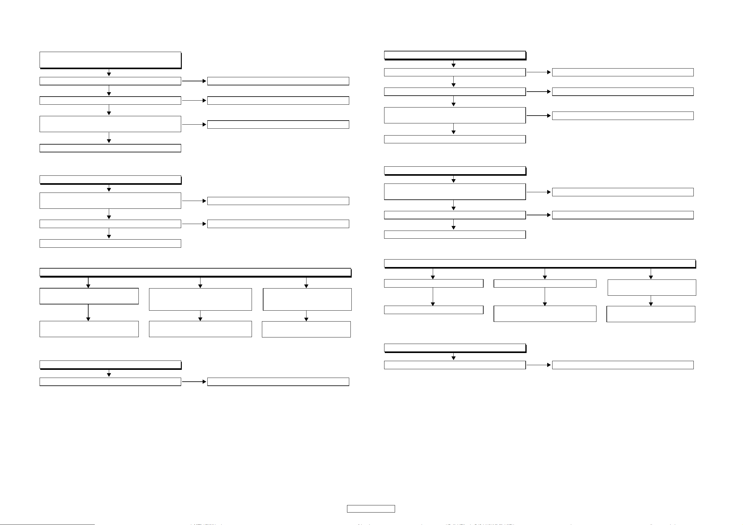
DISASSEMBLY
Y
T
• Disassemble in order of the arrow of the figure of following flow.
下記フロー図の矢印の順番にはずしてください。
• In the case of the re-assembling, assemble it in order of the reverse of the following flow.
再組み立ての場合は、下記のフローの逆の順番に組立ててください
• In the case of the re-assembling, observe "attention of assembling" it.
再組み立ての場合は、「組立のご注意」を遵守してください。
TOP COVER SUB ASS
REAR PANEL FRONT PANEL SUB ASSY ETHERNET UNIT
Refer to "EXPLOTED VIEW" Refer to "DISASSEMBLY 1.FRNOT PANEL SUB ASSY" Refer to "DISASSEMBLY 4.ETHERNET UNIT"
MICON/FLD UNIT (Ref. No. of EXPLODED VIEW : 1-1 ) ETHERNET UNIT (Ref. No. of EXPLODED VIEW : 3 )
P.SW UNIT (Ref. No. of EXPLODED VIEW : 1-3 )
CONNECT UNIT (Ref. No. of EXPLODED VIEW : - )
ENCORDER UNIT (Ref. No. of EXPLODED VIEW : 1-2 )
Refer to "DISASSEMBLY 2.POWER SUPPLY UNIT" AUDIO SIGNAL UNIT (Ref. No. of EXPLODED VIEW : 4-2 )
POWER SUPPLY UNIT (Ref. No. of EXPLODED VIEW : 1-4 )
POWER TRANS SUB TRANS and "EXPLODED VIEW"
Refer to "EXPLOTED VIEW" Refer to "DISASSEMBLY 3.SUB TRANS" POWER AMP UNIT (Ref. No. of EXPLODED VIEW : 2 )
and "EXPLODED VIEW" and "EXPLODED VIEW"
INPUT UNIT & AUDIO SIGNAL UNI
Refer to "DISASSEMBLY 5.INPUT UNIT & AUDIO SIGNAL UNIT"
and "EXPLODED VIEW"
POWER SUPPLY UNIT INPUT UNIT (Ref. No. of EXPLODED VIEW : 4-1 )
and "EXPLODED VIEW"
ETHERNET UNIT (6 units)
Refer to "DISASSEMBLY 6.ETHERNET UNIT (6 units)"
and "EXPLODED VIEW"
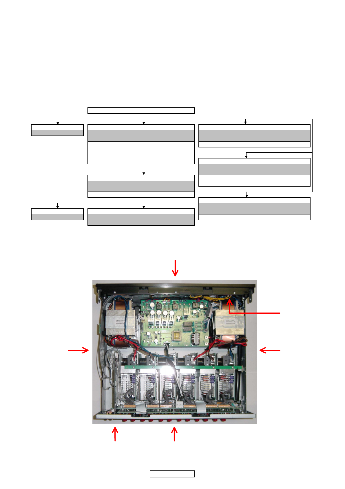
The viewpoint of each photograph
(photography direction)
各図の視点(撮影方向)
Front side
Top view
Picture C
Picture A
Picture F
Picture D
Picture BPicture E
7
POA-3012CI
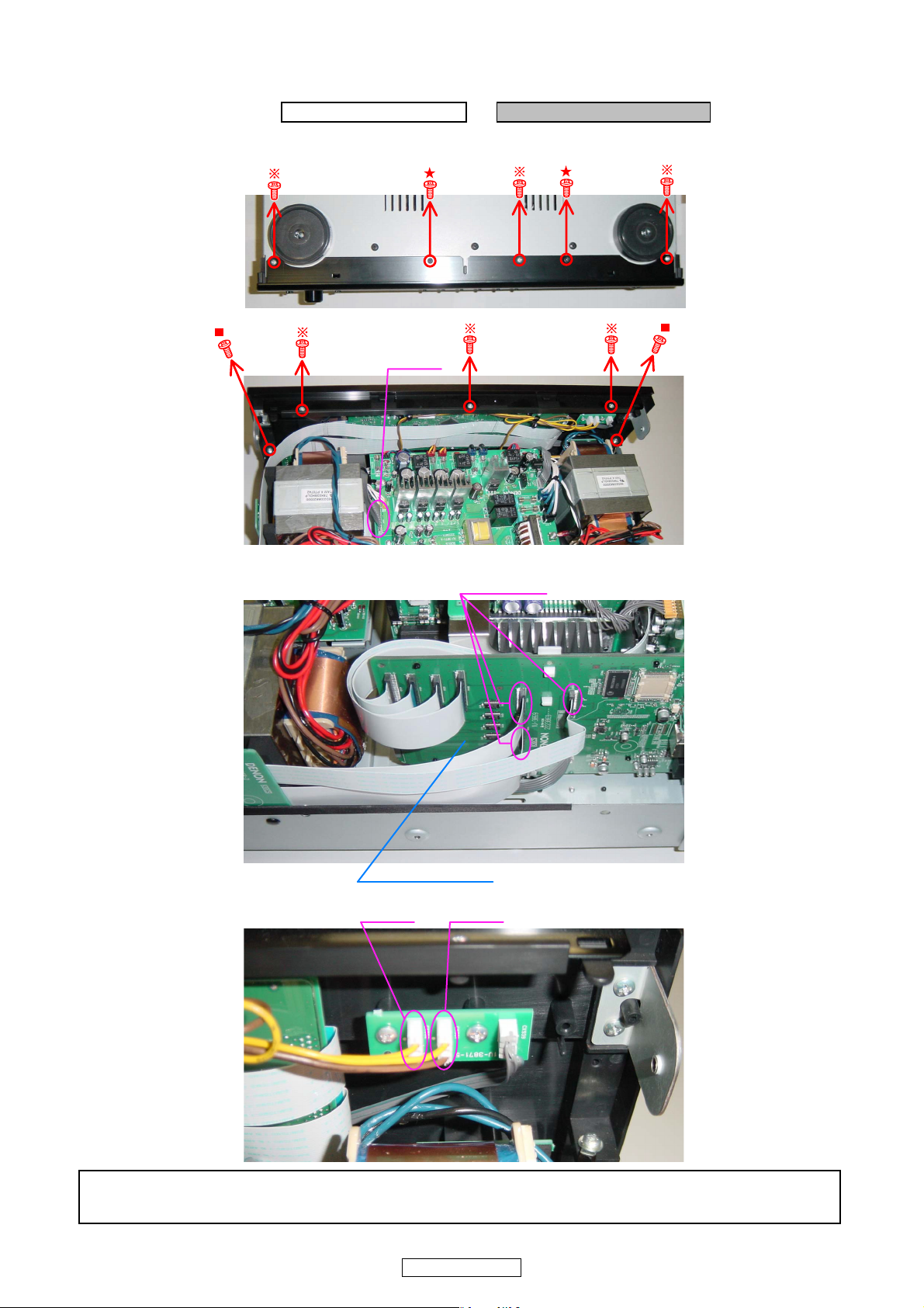
1. FRONT PANEL SUB ASSY
proceeding (手順): TOP COVER SUB ASSY → FRONT PANEL SUB ASSY
(1) Remove the screws. ( ねじをはずす。)
Bottom view
CX121
Picture B
(2) Disconnect the connector wire and FFC Cables. (コネクターワイヤーと FFCケーブルをはずす。)
FFC CABLE
Picture B
ETHERNET UNIT
CX932 CX931
Picture F
Please refer to
FRONTPANELSUBASSY の各基板のはずしかたは "EXPLODEDVIEW" を参照してください。
"EXPLODED VIEW "
for the disassembly method of each P.W.B included in FRNOT PANEL SUB ASSY.
8
POA-3012CI
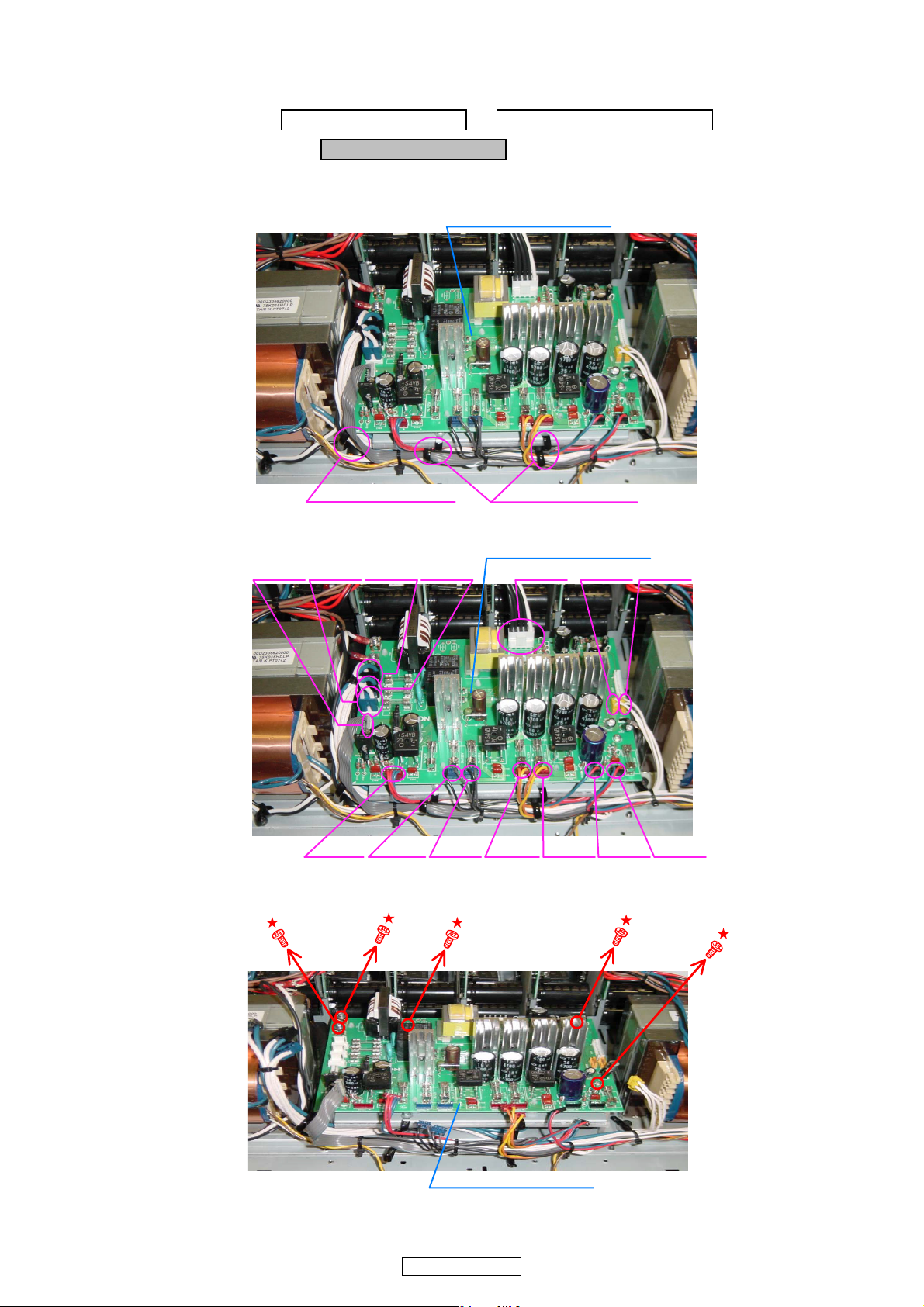
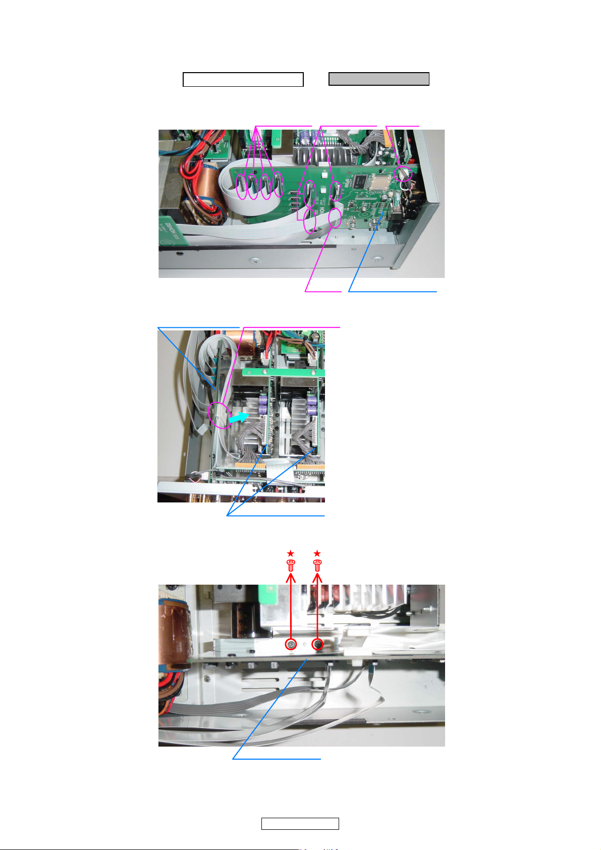
2. POWER SUPPLY UNIT
proceeding (手順): TOP COVER SUB ASSY → FRONT PANEL SUB ASSY
→ POWER SUPPLY UNIT
(1) Loose the cord holders. ( コードホルダーをゆるめる。)
POWER SUPPLY UNIT
Picture A
Cord holder : Loose Cord holder : Loose
(2) Disconnect the connector wires.(コネクターワイヤーをはずす。)
POWER SUPPLY UNIT
CX021CX022CX023 CX058 CX032 CX031CX062
Picture A
CX041
(3) Remove the screws.(ねじをはずす。)
Picture A
CX936 CX935 CX933 CX934 CX938 CX937
(E2 MODEL)
POWER SUPPLY UNIT
9
POA-3012CI
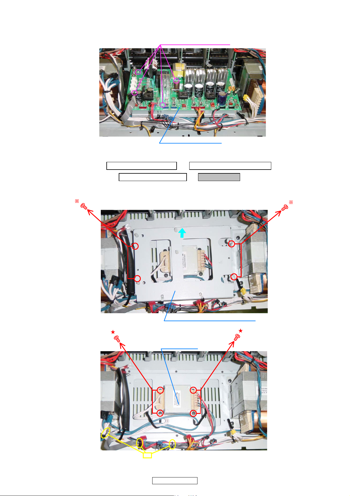
(4) POWER SUPPLY UNIT board off the PCB HOLDER.(PCBHOLDER から POWERSUPPLYUNIT基板をはずす。)
PCB HOLDER : Disconnect
Picture A
POWER SUPPLY UNIT
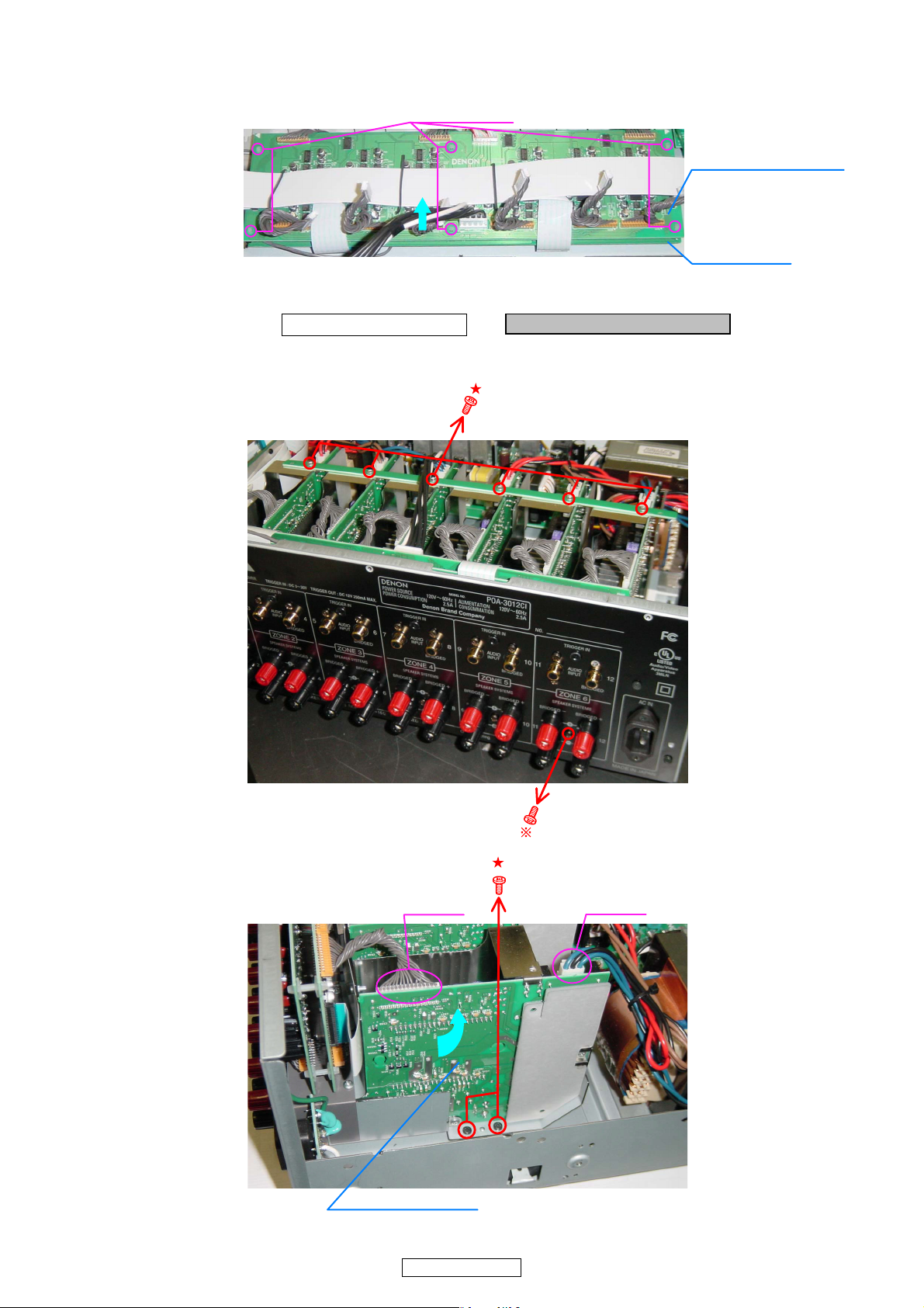
3. SUB TRANS
proceeding (手順): TOP COVER SUB ASSY → FRONT PANEL SUB ASSY
→ POWER SUPPLY UNIT → SUB TRANS
(1) Remove the screws.( ねじをはずす。)
Picture A
Picture A
POWER PWB BRACKET SUB ASS
SUB TRANS
cut
POA-3012CI
10
4. ETHERNET UNIT
proceeding (手順): TOP COVER SUB ASSY → ETHERNET UNIT
(1) Disconnect the connector wires and FFC Cables.(コネクタワイヤーと FFC ケーブルをはずす。)
FFC CABLE CY039
Picture C
FFC CABLE
(2) Loose the FFC Holder.(FFCホルダーをゆるめる。)
ETHERNET UNIT
Picture E
(3) Remove the screws.(ねじをはずす。)
FFC HOLDER : Loose
POWER AMP UNIT
CY062
ETHERNET UNIT
Picture C
ETHERNET UNIT
11
POA-3012CI
Picture B
(4) Disconnect the EHTHERNET UNIT.(ETHERNETUNIT をはずす。)
Picture B
ETHERNET UNIT
5. AUDIO SIGNAL UNIT & INPUT UNIT
proceeding (手順): TOP COVER SUB ASSY → AUDIO SIGNAL UNIT & INPUT UNIT
(1) Disconnect the connector wire and FFC Cables, and remove the screw.(コネクタワイヤー、FFC ケーブル、ねじを
はずす。
CX058FFC CABLE
CX151
Picture B
AUDIO SIGNAL UNIT
INPUT UNIT
12
POA-3012CI
(2) AUDIO SIGNAL UNIT board off the INPUT UNIT.(AUDIOUNIT を INPUTUNIT からはずす。)
PCB HOLDER
Picture B
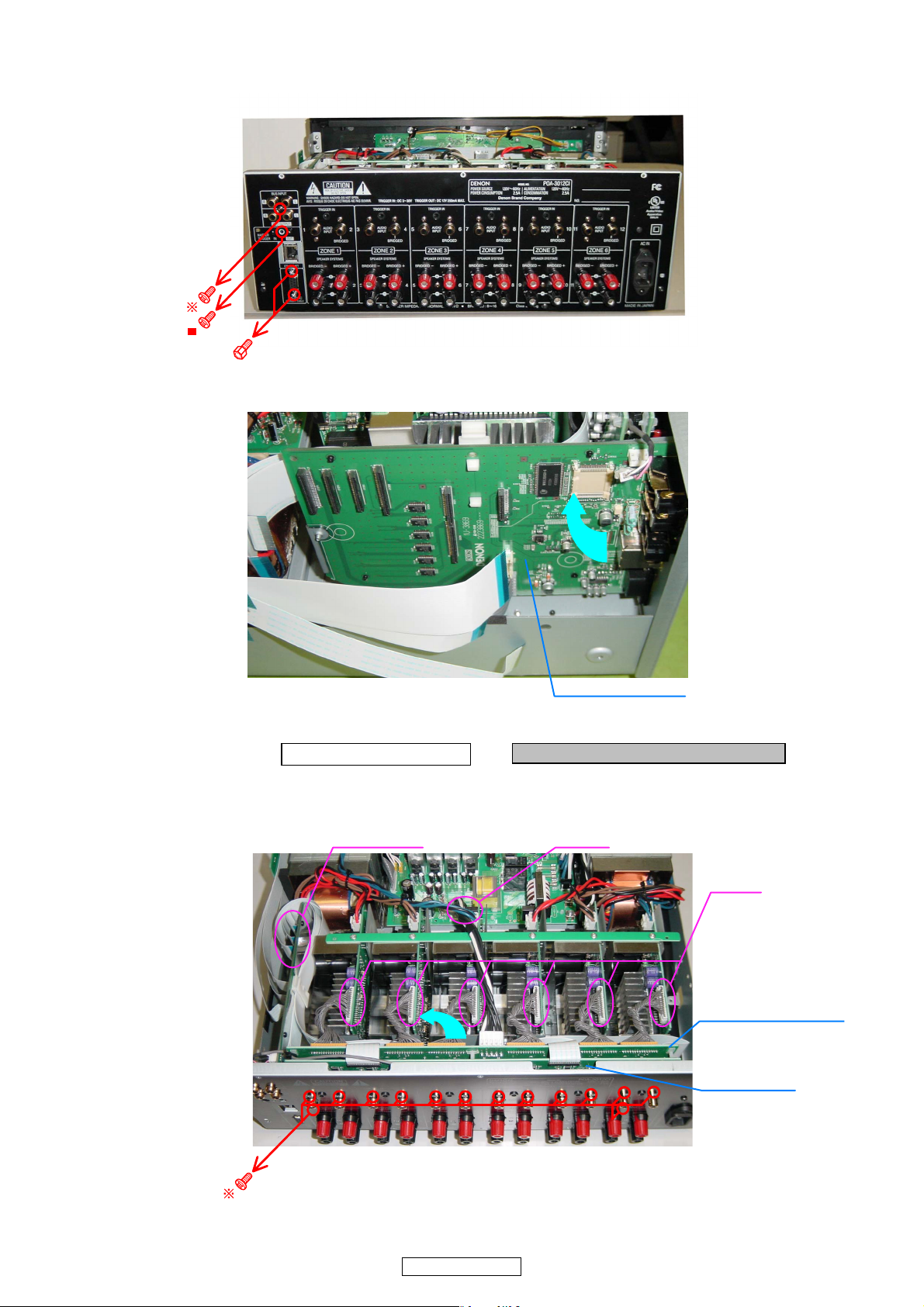
6. POWER AMP UNIT (6 units).
proceeding (手順): TOP COVER SUB ASSY → POWER AMP UNIT (6 units)
(1) Remove the screws and disconnect the connector wires.(ねじとコネクタワイヤーをはずす。)
AUDIO SIGNAL UNIT
INPUT UNIT
Picture B
Picture D
CX031CX151
POWER AMP UNIT
13
POA-3012CI

7. REAR PANEL
proceeding (手順): TOP COVER SUB ASSY → REAR PANEL
Please refer to "EXPLODED VIEW " for the disassembly method of REAR PANEL.
REARPANEL のはずしかたは "EXPLODEDVIEW" を参照してください。
8. POWER TRANS
proceeding (手順): TOP COVER SUB ASSY → FRONT PANEL SUB ASSY
→ POWER TRANS
Please refer to "EXPLODED VIEW " for the disassembly method of POWER TRANS.
POWERTRANS のはずしかたは "EXPLODEDVIEW" を参照してください。
14
POA-3012CI
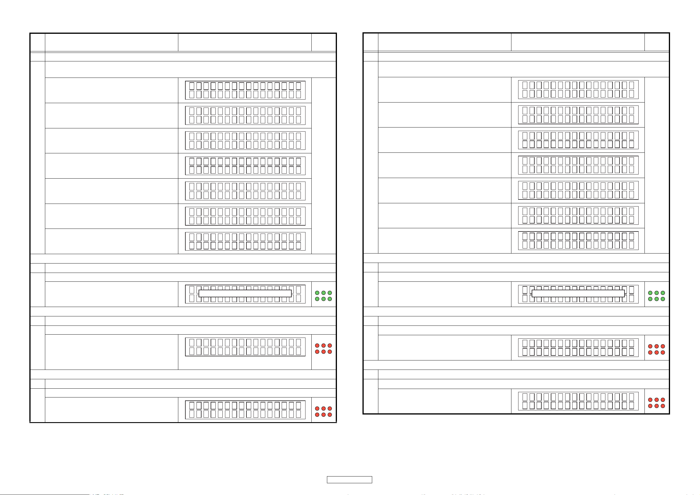
SPECIAL MODE
特殊モード
No. Function Display
1 Version display
• Connect the power cord to the power outlet while simultaneously pressing the ZONE 6 and MENU buttons.
• The item number is displayed replay from q to u each time the DISPLAY button is pressed.
q Serial No
w Main Version
e DM850 Version
r DM850 Version
t DM850 Version
y DM850 Version
Se r i a l No .
nnnnnnnnnn
Ve r . : 00 . 3 4
z Ethernet IMG
I200803270812
z Ethernet BL
B20070702073 3
z Ethernet CNE
C 20080318
z Ethernet WEB
W200803270 801
ZONE
LED
Don't
Care
No. 動作 FL 表示管
1 バージョン表示
・ 本体 ZONE6 ボタンと MENU ボタンを同時に押しながら AC コードを接続する。
DISPLAY ボタンを押すとごとに q から u の表示を繰り返す。
q SerialNo
w MainVersion
e DM850 の Version
r DM850 の Version
t DM850 の Version
y DM850 の Version
Se r i a l No .
nnnnnnnnnn
Ve r . : 00 . 3 4
z Ethernet IMG
I200803270812
z Ethernet BL
B20070702073 3
z Ethernet CNE
C 20080318
z Ethernet WEB
W200803270 801
ZONE
LED
Don't
Care
u Mac Address
z Ethernet MAC
nnnnnn - nn nnnn
2 Compulsorily ROM rewriting mode
When failing in rewriting to Main Microprocessor ROM, it's rewritten in DENON WRITER compulsorily.
・ Connect the power cord to the power outlet while
simultaneously pressing the ZONE 5 and u buttons.
Off
3 Initialization mode (Excluding Installer setup)
z Backup data excluding the data for Installer setup is initialized.
・ Connect the power cord to the power outlet while
simultaneously pressing the ZONE 5 and DISPLAY
buttons.
When the button is released, it returns to Normal
Mode.
z EEPROM I NI T . z
4 Service initialization mode
z All data is initialized.
• Connect the power cord to the power outlet while
simultaneously pressing the ZONE 3 and DISPLAY
buttons.
z EEPROM I NI T . z
Green
Red
Red
u MacAddress
z Ethernet MAC
nnnnnn - nn nnnn
2 強制 ROM 書き換えモード
z Main マイコンの ROM への書き換えが途中で失敗した場合に、強制的に DENONWRITER で書き換えをおこなう。
・ 本体 ZONE5 ボタンと u ボタンを同時に押しながら
AC コードを接続する。
Off
3 初期化モード (Installersetup 除く )
z Installersetup 用のデータを除いたバックアップデータの初期化をおこなう。
・ 本体 ZONE5 ボタンと DISPLAY ボタンを同時に押し
ながら AC コードを接続する。
ボタンを離すと、NormalMode に戻る。
z EEPROM I NI T . z
4 サービス初期化モード
z 全てのデータの初期化をおこなう。
・ 本体 ZONE3 ボタンと DISPLAY ボタンを同時に押し
ながら AC コードを接続する。
z EEPROM I NI T . z
Green
Red
Red
15
POA-3012CI
No. Function Display
5 Installer initialization mode
z Only the data for Installer setup is initialized
• Connect the power cord to the power outlet while
simultaneously pressing the ZONE 3 and SETUP buttons.
Don't Care
ZONE
LED
Don't
Care
No. 動作 FL 表示管
5 インストーラー初期化モード
z Installersetup 用のデータのみの初期化をおこなう。
・ 本体 ZONE3 ボタンと SETUP ボタンを同時に押しな
がら AC コードを接続する。
Don't Care
ZONE
LED
Don't
Care
6 Installer mode
z Installer Setup is executed. The item of Installer Setup is displayed on the Web screen.
・ Connect the power cord to the power outlet while
simultaneously pressing the ZONE 4 and SETUP buttons.
7 Recovery update mode
When failing in rewriting to Main Microprocessor ROM, it's rewritten in DPMS compulsorily.
・ Connect the power cord to the power outlet while
simultaneously pressing the ZONE 6 and u buttons.
Ma i n F i r m - - - m i n
Upda t i n g
Don't Care
Don't
Care
Don't
Care
6 インストーラーモード
z InstallerSetup をおこなう。Web 画面上に InstallerSetup の項目を表示する。
・ 本体 ZONE4 ボタンと SETUP ボタンを同時に押しな
がら AC コードを接続する。
Don't Care
7 リカバーアップデートモード
z Main マイコンの ROM への書き換えが途中で失敗した場合に、強制的に DPMS で書き換えをおこなう。
・ 本体 ZONE6 ボタンと u ボタンを同時に押しながら
AC コードを接続する。
Ma i n F i r m - - - m i n
Upda t i n g
Don't
Care
Don't
Care
16
POA-3012CI
TROUBLE SHOOTING
いいえ
いいえ
T101の断線またはD101‑104の故障
はい
はい
はい
フローチャートNO.1
電源が入らない。(電源表示LEDが点灯しない)
C147に6Vの電圧が供給されているか?
C150に4Vの電圧が供給されているか?
IC104の故障
いいえ
IC701の故障
マイコン(IC701)の19ピンと20ピンにHi(3.3V)
の電圧が出力されているか?
LED(LD707)の故障
いいえ
いいえ
IC701またはTR101‑TR104の故障
はい
はい
フローチャートNO.2
電源は入るがFLDが点灯しない。
電源リレーRL101、102のコイルに6Vが供給されている
か?
ヒューズ(F101、102、107、109)は正常か?
トランスの故障
FLD電源回路またはFL701の故障
通信ユニットの故障
フローチャートNO.4
パソコンを使って設定ができない。
パソコンに設定画面が表示できない。
電源回路または温度検出回路の故障
フローチャートNO.3
電源は入りFLDは点灯するが音が出ない。
ZONEの動作表示LEDが6個全て赤点滅
音の出ないZONEの動作表示LEDが赤点滅
赤点滅ZONEのパワーアンプユニットの
故障
インプットユニットまたはオー
ディオシグナルユニットの故障
ZONEの動作表示LEDは通常どおり
(緑または橙点灯)
FLOW CHART NO.1
The power cannot be turned on.
(Power indication LED dose not light)
トラブルシューティング
Is the voltage of 6V supplied to C147?
YES
Is the voltage of 4V supplied to C150?
YES
Is the voltage of Hi (3.3V) output to 19 pins and 20 pins
of the microprocessor (IC701)?
Trouble of LED(LD707).
FLOW CHART NO.2
Power is turned on, but FLD does not light.
Is 6V supplied to the coil of power supply relay RL101
and 102?
Are fuse (F101, 102, 107, 109) normal?
The power supply circuit of FLD or trouble of FL701.
FLOW CHART NO.3
YES
YES
YES
Power is turned on and FLD lights up, but sound is not output.
NO
NO
NO
NO
NO
Disconnection of T101 or trouble of D101-104.
Trouble of IC104.
Trouble of IC701.
Trouble of IC701 and TR101-TR104.
Trouble of the transformer.
When all zone operation mode LED
flashes in red.
Trouble of power circuit or temperature
detector.
FLOW CHART NO.4
Using the PC, setting is not possible.
The screen of the setting is not displayed to the PC.
zone operation mode LED
When
the sound does not produce flashes in
red.
Trouble of the power amplifier unit of
ZONE flashing in red.
Trouble of communication unit.
which
When Zone operation mode LED
lights normally.
(Green or an orange)
Trouble of input unit or audio
signal unit.
17
POA-3012CI
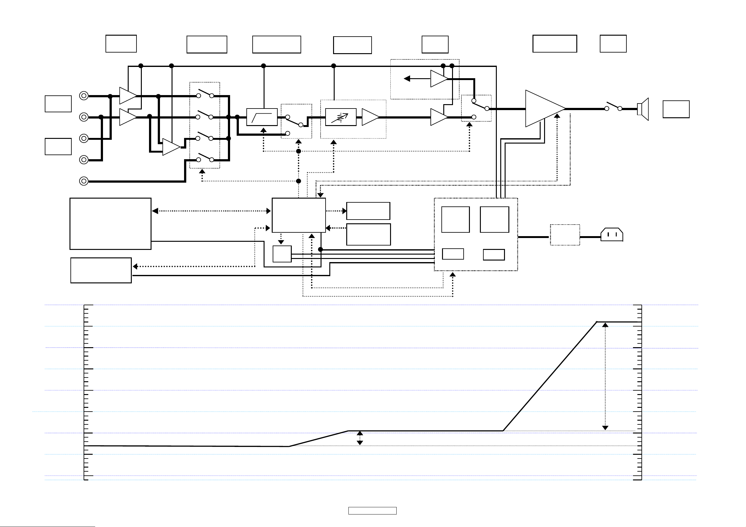
BLOCK/LEVEL DIAGRAM
BUS
INPUT
CASCADE
OUT
COMMUNICATION
(BCOIC-DM850-QCL/
RTL8201CP)
RS232C
Ethernet
12V TRIGGER
LCH
0dB
BUFFER
+
INPUT SELECT
4052
H.P.F
80Hz 12dB/oct
4053
ELECTORIC
VOLUME
ELECTRIC VOLUME
−∞㨪+4.0dB
dB
Odd CH ONLY
Even ch
PRE-AMP
+
0dB
Power Amp
Odd CH -25.0dB
Even CH 25.0dB
RCH
+
LCH ±5V
RCH ±30V
AUX
+
AUDIO SIGNAL SENSE
L/R/L+R/AUX/H.P.F/
BRIDGE
TC94A32
CONTROL
RS232C/Ethernet
(u-com)
+
P.SW LED
−
0dB
P.T
EI96-65
4053
±12V
P.T
EI96-65
ENCODER
INPUT×6/OUT×1
TRIG IN / OUT
TACT.SW
FL
FL 㪑㩷+48V 250mV
AC5.6V
+12V 200mA
+5V
AC_OFF
M.T
AC RELAY1,2
S.T
POWER AMP
DA428440-30
ENA
LINE
FILTER
SPEAKER
RELAY
SPEAKER
OUT
PROTECTION
SIGNAL
TEMPERATURE/D.C/
OVER CURRENT
AC IN LET
+30dB
+20dB
+10dB
IN PUT
550mVrms
-10dB
0dB
VARIABLE GAIN VOLUME
−∞〜+4.0dB
4.0dB
25.0dB
+30dB
+26dB
+20dB
+10dB
0dB
-10dB
SPEAKER OUT
15.5Vrms (8ohm)
18
POA-3012CI
SEMICONDUCTORS
Only major semiconductors are shown, general semiconductors etc. are omitted to list.
主な半導体を記載しています。汎用の半導体は記載を省略しています。
1. IC’s
BCOIC-DM850-CQL (IC905)
19
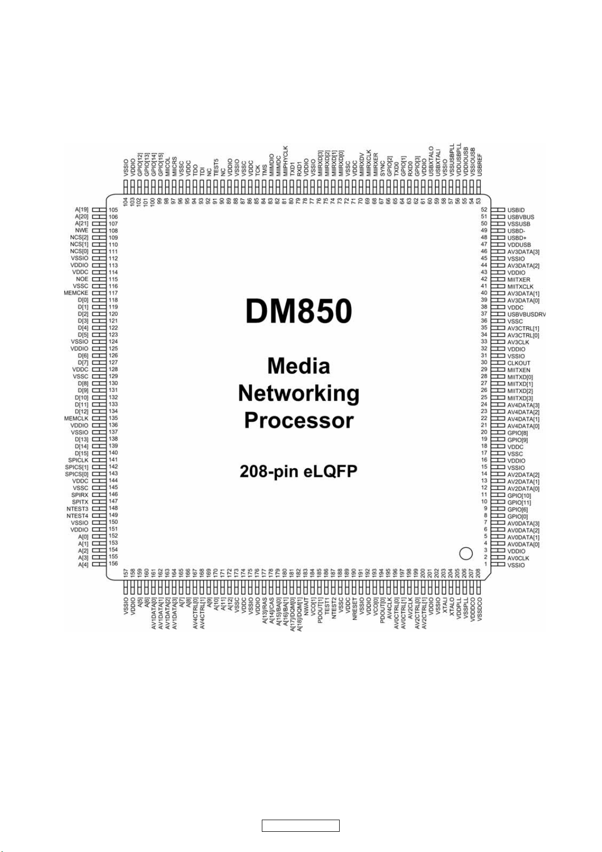
POA-3012CI
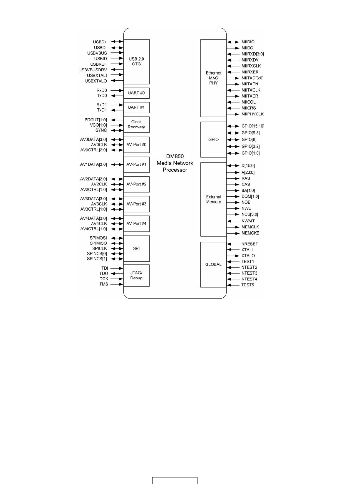
BCOIC-DM850-CQL Functional Diagram
20
POA-3012CI
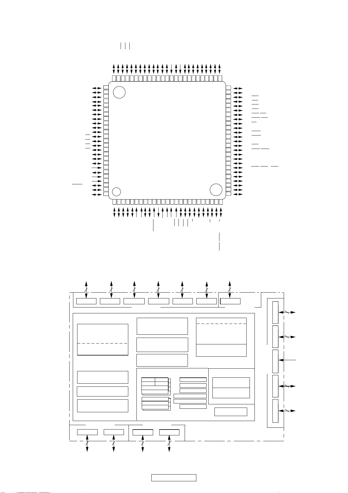
M3062LFGPGP (IC701)
)
)
)
)
)
)
3
/D
4
(/D
4
/A
4
2
/AN
4
2
P
4
/D
5
(/D
5
/A
25
/AN
5
P2
5
/D
6
(/D
6
/A
26
/AN
6
2
P
)
6
/D
7
(/D
7
/A
7
2
/AN
7
P2
)
7
5
2
3
4
1
16
1
/A
4
P3
17
1
1
/A
/A
/A
/A
/A
7
0
1
5
6
P3
P4
P4
P3
P3
CC2
V
1
9
10
1
/A
/A
/A
1
2
3
P3
P3
P3
(/-/D
8
/A
0
SS
3
V
P
0
1
2
/D
/D
/-)
/D
1
2
0
3
(/D
(/D
(/D
0
/A
20
/AN
0
P2
1
/A
1
2
/AN
1
2
P
2
/A
22
/AN
2
P2
(/D
3
/A
23
/AN
3
P2
3
4
5
T
T
T
/IN
/IN
/IN
2
11
1
13
14
/D
3
P1
15
/D
/D
/D
/D
4
5
6
7
1
1
P
P1
P
P1
P12/D
P11/D
P10/D
P07/AN07/D
P06/AN06/D
P05/AN05/D
P04/AN04/D
P03/AN03/D
P02/AN02/D
P01/AN01/D
P00/AN00/D
P107/AN7/KI
P106/AN6/KI
P105/AN5/KI
P104/AN4/KI
P103/AN
P102/AN
P101/AN
AV
P100/AN
V
AVcc
P97/AD
TRG/SIN
6
/ANEX1/S
P9
P95/ANEX0/CLK4
OUT
REF
57585960616263646566676869707172737475
76
10
77
9
78
8
79
7
80
6
81
5
82
4
83
3
84
2
85
1
0
86
87
3
88
2
89
1
90
0
91
3
92
2
93
1
SS
94
95
0
96
97
98
4
99
4
00
1
1 2 3 4 5 6 7 8 9 10111213141516171819202122232425
3
IN
IN
OUT
/TB4
/TB3
/S
1
0
IN
/DA
/DA
4
3
9
/TB2
2
P9
P
P9
M16C/62P Group
3
CIN
IN
/X
/S
BYTE
7
/CLK3
IN
CNVss
IN
P8
/TB1
1
/TB0
0
P9
P9
COUT
/X
6
P8
SS
OUT
V
X
RESET
IN
X
CC1
/NMI
V
/INT
5
4
P8
P8
/INT
3
P8
/INT
2
8
P
/U
/U
IN
4
OUT
/TA
1
/TA4
0
P8
P8
0
1
2
IN
/TA3
7
P7
OUT
/TA3
6
7
P
/W
IN
/TA2
5
P7
515253545556
/W
OUT
/TA2
4
P7
/V
IN
/TA1
2
/RTS
2
/CTS
3
P7
50
49
48
47
46
45
44
43
42
41
40
39
38
37
36
35
34
33
32
31
30
29
28
27
26
P42/A
18
P43/A
19
P44/CS0
P45/CS1
P46/CS2
P47/CS3
P50/WRL/WR
P51/WRH/BHE
P5
2
/RD
P53/BCLK
P54/HLDA
P55/HOLD
P56/ALE
P57/RDY/CLK
P60/CTS0/RTS
P61/CLK
P62/RxD0/SCL
P63/TXD0/SDA
P64/CTS1/RTS1/CTS0/CLKS
P65/CLK
P66/RxD1/SCL
P67/TXD1/SDA
P7
P7
P72/CLK2/TA1
OUT
0
0
0
0
1
1
0/TXD2
1
1
/SDA2/TA0
OUT
OUT
(Note)
/V
/RxD2/SCL2/TA0IN/TB5IN(Note)
1
BLOCK DIAGRAM
Port P08Port P18Port P28Port P38Port P48Port P58Port P6
<V
CC2
Internal peripheral functions
Timer (16-bit)
Output (timer A): 5
Input (timer B): 6
Three-phase motor
control circuit
Watchdog timer
(15 bits)
DMAC
(2 channels)
D-A converter
(8bitsX2channels)
<V
CC1
ports> <V
Port P118Port P14
(Note 3) (Note 3)
ports>
A-D converter
(10 bitsX8 channels
Expandable up to 26 channels)
UART or
clock synchronous serial I/O
(8 bitsX3 channels)
CRC arithmetic circuit (CCITT )
(Polynomial : X
16+X12+X5
+1)
M16C/60 series16-bit CPU core
R0LR0H
R1H R1L
R2
R3
A0
A1
FB
CC2
ports>
Port P128Port P13
(Note 3)
INTB
(Note 3)
System clock generator
X
PLL frequency synthesizer
Clock synchronous serial I/O
(8 bitsX2 channels)
SB
USP
ISP
PC
FLG
<V
X
IN-XOUT
CIN-XCOUT
Ring oscillator
Memory
ROM
(Note 1)
RAM
(Note 2)
Multiplier
8
CC1
ports>
<V
CC1
ports>
Port P7
8
Port P8
7
Port P8
5
Port P9
8
Port P10
8
2
8
Note 1: ROM size depends on microcomputer type.
Note 2: RAM size depends on microcomputer type.
Note 3: Ports P11 to P14 exist only in 128-pin version.
21
POA-3012CI
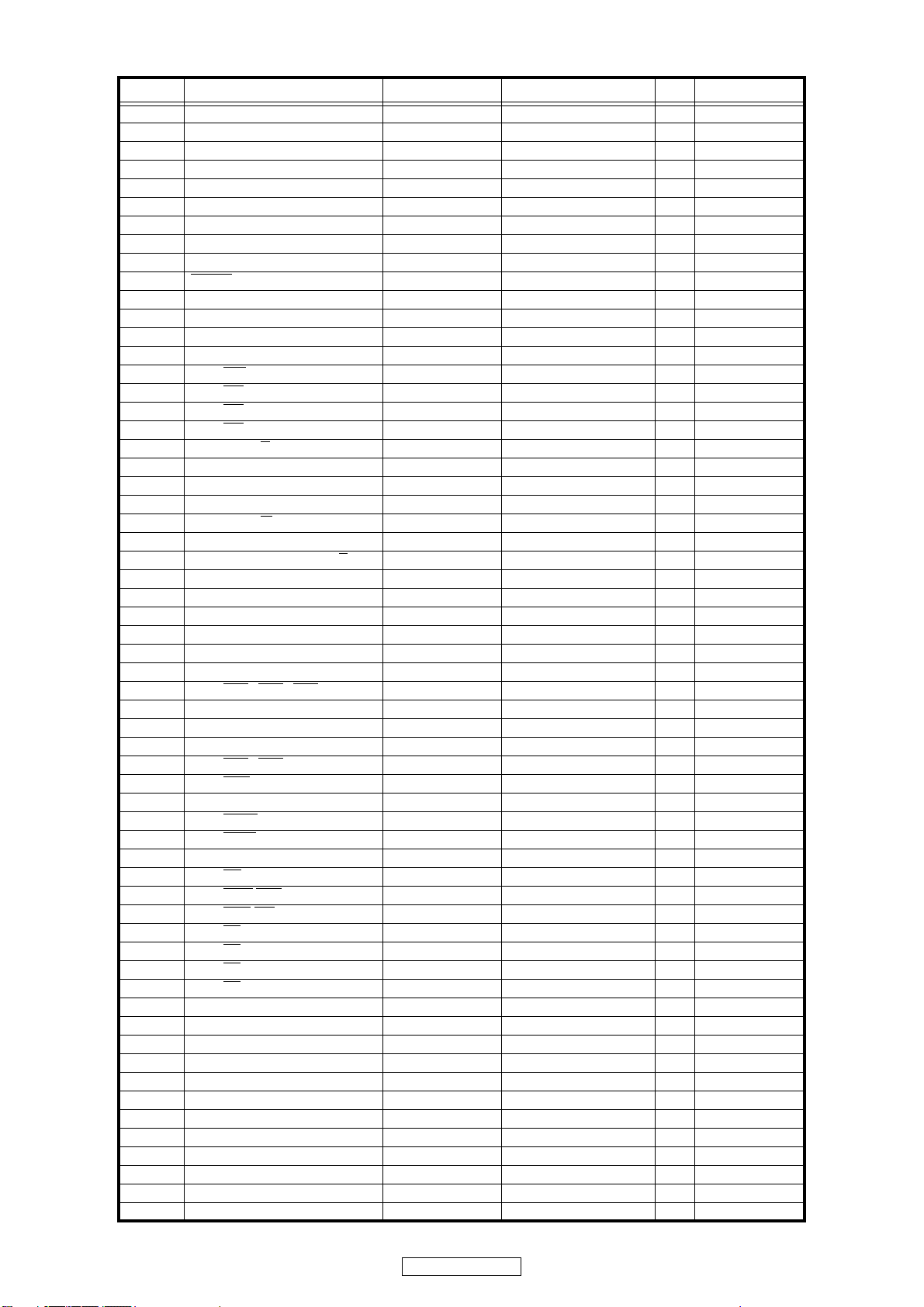
Terminl Function
PIN No. PIN Name Port Name Function I/O Remarks
1 P9_4/DA1/TB4IN LED_G6 O
2 P9_3/DA0/TB3IN FL_RESET O
3 P9_2/TB2IN/SOUT3 LED_G5 O
4 P9_1/TB1IN/SIN3 LED_G4 O
5 P9_0/TB0IN/CLK3 LED_G3 O
6 BYTE VSS VSS I
7 CNVSS CNVSS I
8 P8_7/XCIN LED_G2 O
9 P8_6/XCOUT LED_G1 O
10 RESET
11 XOUT XTAL MAIN OSC O
12 VSS VSS VSS I
13 XIN XTAL MAIN OSC I
14 VCC1 VCC VCC I
15 P8_5/NMI
16 P8_4/INT
17 P8_3/INT
18 P8_2/INT
19 P8_1/TA4IN/U
20 P8_0/TA4OUT/U P.LED_R O
21 P7_7/TA3IN ENC_B ENCODER I
22 P7_6/TA3OUT ENC_A ENCODER I
23 P7_5/TA2IN/W
24 P7_4/TA2OUT/W THERMAL I Error : "H"
25 P7_3/CSTS2/RTS2/TA1IN/V
26 P7_2/CLK2/TA1OUT/V ETH SPICLK ETHERNET O
27 P7_1/RXD2/SCL2/TA0IN/TB5IN ETH RXDMOEI ETHERNET I
28 P7_0/TXD2/SDA2/TA0OUT ETH TXDMIEO ETHERNET O OPEN DRAIN
29 P6_7/TXD1/SDA1 RS232C_TX RS232C O
30 P6_6/RXD1/SCL1 RS232C_RX RS232C I
31 P6_5/CLK1 ETH SPIMIEO ETHERNET O
32 P6_4/CTS
33 P6_3/TXD0/SDA0 TEST TEST I
34 P6_2/RXD0/SCL0 TEST TEST I check mode : "L"
35 P6_1/CLK0 ETH MODE ETHERNET O
36 P6_0/CTS
37 P5_7/RDY
38 P5_6/ALE LED_R5 O
39 P5_5/HOLD
40 P5_4/HLDA
41 P5_3/BCLK E2P_DO O
42 P5_2/RD
43 P5_1/WRH
44 P5_0/WRL
45 P4_7/CS
46 P4_6/CS
47 P4_5/CS
48 P4_4/CS
49 P4_3/A19 CH12 Channel switching O
50 P4_2/A18 CH11 Channel switching O
51 P4_1/A17 CH10 Channel switching O
52 P4_0/A16 CH9 Channel switching O
53 P3_7/A15 CH8 Channel switching O
54 P3_6/A14 CH7 Channel switching O
55 P3_5/A13 CH6 Channel switching O
56 P3_4/A12 CH5 Channel switching O
57 P3_3/A11 CH4 Channel switching O
58 P3_2/A10 CH3 Channel switching O
59 P3_1/A9 CH2 Channel switching O
60 VCC2 VCC2 VCC I
RESET RESET I
PULL UP I
2/ZP ETH REQ ETHERNETNET I
1 M_TRIG MASTER TRIGGER IN I signal : "L"
0P.SWTACT KEYI
P. L ED _ G O
FLCS FLD CHIP SERECT O
ETH SPIMOEI ETHERNET O
1/RTS1/CTS0/CLKS1 ETH RESET ETHERNET O
0/RTS0 ETH SPICS ETHERNET O
/CLKOUT LED_R6 O
EPM O
E2P_CLK O
E2P_DI I
/BHE E2P_CS O
/WR CE WRIGHT/READ I
3LED_R4 O
2LED_R3 O
1LED_R2 O
0LED_R1 O
22
POA-3012CI
 Loading...