

Denon POA-3012CI Owners Manual

MULTI CHANNEL POWER AMPLIFIER
POA-3012CI
Owner’s Manual
Bedienungsanleitung
ENGLISH
CAUTION
RISK OF ELECTRIC SHOCK
DO NOT OPEN
n
DEUTSCH
SAFETY PRECAUTIONS
CAUTION:
TO REDUCE THE RISK OF ELECTRIC SHOCK, DO NOT REMOVE
COVER (OR BACK). NO USER-SERVICEABLE PARTS INSIDE.
REFER SERVICING TO QUALIFIED SERVICE PERSONNEL.
The lightning flash with arrowhead symbol, within an equilateral
triangle, is intended to alert the user to the presence of
uninsulated “dangerous voltage” within the product’s enclosure
that may be of sufficient magnitude to constitute a risk of electric
shock to persons.
The exclamation point within an equilateral triangle is intended
to alert the user to the presence of important operating
and maintenance (servicing) instructions in the literature
accompanying the appliance.
WARNING:
TO REDUCE THE RISK OF FIRE OR ELECTRIC SHOCK, DO NOT
EXPOSE THIS APPLIANCE TO RAIN OR MOISTURE.
CAUTION:
• The ventilation should not be impeded by covering the ventilation
openings with items, such as newspapers, tablecloths, curtains,
etc.
• No naked flame sources, such as lighted candles, should be
placed on the unit.
• Observe and follow local regulations regarding battery disposal.
• Do not expose the unit to dripping or splashing fluids.
• Do not place objects filled with liquids, such as vases, on the
unit.
ACHTUNG:
• Die Belüftung sollte auf keinen Fall durch das Abdecken der
Belüftungsöffnungen durch Gegenstände wie beispielsweise
Zeitungen, Tischtücher, Vorhänge o. Ä. behindert werden.
• Auf dem Gerät sollten keinerlei direkte Feuerquellen wie
beispielsweise angezündete Kerzen aufgestellt werden.
• Bitte beachten Sie bei der Entsorgung der Batterien die örtlich
geltenden Umweltbestimmungen.
• Das Gerät sollte keiner tropfenden oder spritzenden Flüssigkeit
ausgesetzt werden.
• Auf dem Gerät sollten keine mit Flüssigkeit gefüllten Behälter
wie beispielsweise Vasen aufgestellt werden.
IMPOTANT SAFETY
INSTRUCTIONS
1. Read these instructions.
2. Keep these instructions.
3. Heed all warnings.
4. Follow all instructions.
5. Do not use this apparatus near water.
6. Clean only with dry cloth.
7. Do not block any ventilation openings.
Install in accordance with the manufacturer's instructions.
8. Do not install near any heat sources such as radiators, heat registers,
stoves, or other apparatus (including amplifiers) that produce heat.
9. Do not defeat the safety purpose of the polarized or grounding-type plug. A
polarized plug has two blades with one wider than the other. A grounding
type plug has two blades and a third grounding prong. The wide blade or the
third prong are provided for your safety. If the provided plug does not fit into
your outlet, consult an electrician for replacement of the obsolete outlet.
10. Protect the power cord from being walked on or pinched particularly at
plugs, convenience receptacles, and the point where they exit from the
apparatus.
11. Only use attachments/accessories specified by the manufacturer.
12. Use only with the cart, stand, tripod, bracket, or table
specified by the manufacturer, or sold with the apparatus.
When a cart is used, use caution when moving the cart/
apparatus combination to avoid injury from tip-over.
13. Unplug this apparatus during lightning storms or when
unused for long periods of time.
14. Refer all servicing to qualified service personnel.
Servicing is required when the apparatus has been damaged in any way,
such as power-supply cord or plug is damaged, liquid has been spilled or
objects have fallen into the apparatus, the apparatus has been exposed to
rain or moisture, does not operate normally, or has been dropped.
CAUTION:
To completely disconnect this product from the mains, disconnect
the plug from the wall socket outlet.
The mains plug is used to completely interrupt the power supply to
the unit and must be within easy access by the user.
VORSICHT:
Um dieses Gerät vollständig von der Stromversorgung abzutrennen,
ziehen Sie bitte den Stecker aus der Wandsteckdose.
Der Netzstecker wird verwendet, um die Stromversorgung zum
Gerät völlig zu unterbrechen; er muss für den Benutzer gut und
einfach zu erreichen sein.
FCC INFORMATION (For US customers)
1. COMPLIANCE INFORMATION
Product Name: Multi Channel Power Amplifier
Model Number: POA-3012CI
This product complies with Part 15 of the FCC Rules. Operation is subject
to the following two conditions: (1) this product may not cause harmful
interference, and (2) this product must accept any interference received,
including interference that may cause undesired operation.
Denon Electronics (USA), LLC
(a D & M Holdings Company)
100 Corporate Drive
Mahwah, NJ 07430-2041
Tel. (800) 497-8921
2. IMPORTANT NOTICE: DO NOT MODIFY THIS PRODUCT
This product, when installed as indicated in the instructions contained
in this manual, meets FCC requirements. Modification not expressly
approved by DENON may void your authority, granted by the FCC, to use
the product.
3. NOTE
This product has been tested and found to comply with the limits for
a Class B digital device, pursuant to Part 15 of the FCC Rules. These
limits are designed to provide reasonable protection against harmful
interference in a residential installation.
This product generates, uses and can radiate radio frequency energy and,
if not installed and used in accordance with the instructions, may cause
harmful interference to radio communications. However, there is no
guarantee that interference will not occur in a particular installation. If this
product does cause harmful interference to radio or television reception,
which can be determined by turning the product OFF and ON, the user
is encouraged to try to correct the interference by one or more of the
following measures:
• Reorient or relocate the receiving antenna.
• Increase the separation between the equipment and receiver.
• Connect the product into an outlet on a circuit different from that to
which the receiver is connected.
• Consult the local retailer authorized to distribute this type of product or
an experienced radio/TV technician for help.
This Class B digital apparatus complies with Canadian ICES-003.
Cet appareil numérique de la classe B est conforme à la norme NMB-003 du
Canada.
I
DEUTSCH
ENGLISH
NOTE ON USE / HINWEISE ZUM GEBRAUCH
n
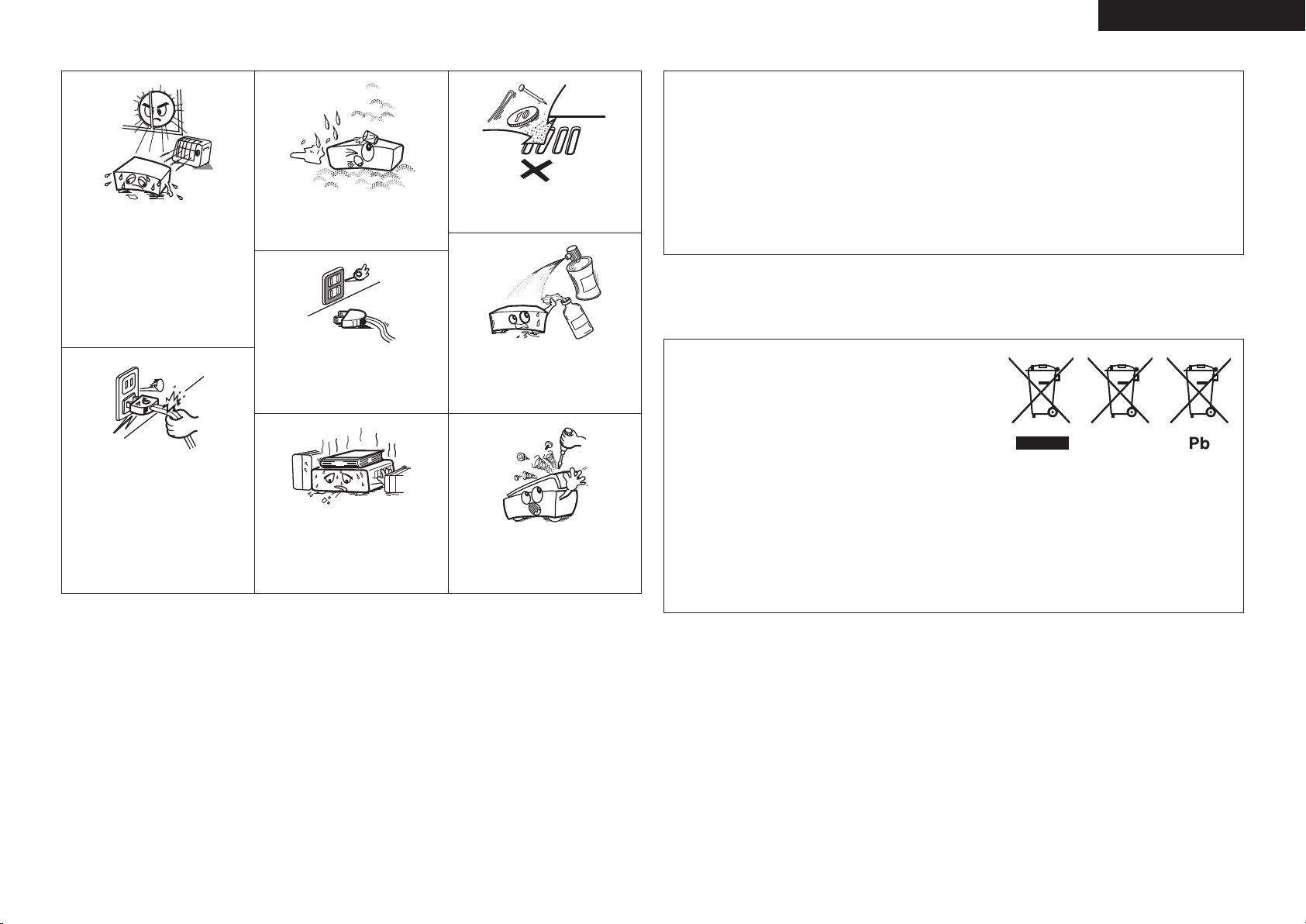
• Keep the unit free from moisture, water,
and dust.
• Halten Sie das Gerät von Feuchtigkeit,
• Avoid high temperatures.
Allow for sufficient heat dispersion when
installed in a rack.
• Vermeiden Sie hohe Temperaturen.
Beachten Sie, dass eine ausreichende
Belüftung gewährleistet wird, wenn das
Gerät auf ein Regal gestellt wird.
• Handle the power cord carefully.
Hold the plug when unplugging the cord.
• Gehen Sie vorsichtig mit dem Netzkabel
um.
Halten Sie das Kabel am Stecker, wenn Sie
den Stecker herausziehen.
Wasser und Staub fern.
• Unplug the power cord when not using the
unit for long periods of time.
• Wenn das Gerät längere Zeit nicht
verwendet werden soll, trennen Sie das
Netzkabel vom Netzstecker.
* (For apparatuses with ventilation holes)
• Do not obstruct the ventilation holes.
• Decken Sie den Lüftungsbereich nicht ab.
• Do not let foreign objects into the unit.
Lassen Sie keine fremden Gegenstände in
•
das Gerät kommen.
• Do not let insecticides, benzene, and
thinner come in contact with the unit.
• Lassen Sie das Gerät nicht mit Insektiziden,
Benzin oder Verdünnungsmitteln in
Berührung kommen.
• Never disassemble or modify the unit in
any way.
• Ne jamais démonter ou modifier l’appareil
d’une manière ou d’une autre.
For Europe model
n
DECLARATION OF CONFORMITY
We declare under our sole responsibility that this product, to which this declaration relates, is in
conformity with the following standards:
EN60065, EN55013, EN55020, EN61000-3-2 and EN61000-3-3.
Following the provisions of 2006/95/EC and 2004/108/EC Directive.
ÜBEREINSTIMMUNGSERKLÄRUNG
Wir erklären unter unserer Verantwortung, daß dieses Produkt, auf das sich diese Erklärung bezieht,
den folgenden Standards entspricht:
EN60065, EN55013, EN55020, EN61000-3-2 und EN61000-3-3.
Entspricht den Verordnungen der Direktive 2006/95/EC und 2004/108/EC.
DENON Europe
Division of D&M Germany GmbH
An der Landwehr 19, Nettetal,
D-41334 Germany
A NOTE ABOUT RECYCLING:
This product’s packaging materials are recyclable and can be
reused. Please dispose of any materials in accordance with the local
recycling regulations.
When discarding the unit, comply with local rules or regulations.
Batteries should never be thrown away or incinerated but disposed
of in accordance with the local regulations concerning battery
disposal.
This product and the supplied accessories, excluding the batteries,
constitute the applicable product according to the WEEE directive.
HINWEIS ZUM RECYCLING:
Das Verpackungsmaterial dieses Produktes ist zum Recyceln geeignet und kann wieder verwendet werden. Bitte
entsorgen Sie alle Materialien entsprechend der örtlichen Recycling-Vorschriften.
Beachten Sie bei der Entsorgung des Gerätes die örtlichen Vorschriften und Bestimmungen.
Die Batterien dürfen nicht in den Hausmüll geworfen oder verbrannt werden; bitte entsorgen Sie die Batterien gemäß
der örtlichen Vorschriften.
Dieses Produkt und das im Lieferumfang enthaltene Zubehör (mit Ausnahme der Batterien!) entsprechen der WEEEDirektive.
II
ENGLISH
r
q w
Getting Started
n Contents
Getting Started
Connections Setup Operations Troubleshooting
Accessories ······················································································1
Cautions on Handling ·····································································1
Cautions on Installation ································································· 1
Part Names and Functions ·····························································2
Front Panel ····················································································· 2
Rear Panel ······················································································3
Connections
Preparations ···················································································· 4
Before Connecting ·········································································4
Cables Used for Connections ························································4
Speaker Connections ·····································································5
Connection Method When Outputting
2 Channels From One ZONE ··························································5
Connection Method for BRIDGED Output ·····································5
Input Connections ··········································································7
BUS INPUT Connections ································································7
Specifications
AUDIO INPUT Connections····························································7
Connections to Other Devices ·······················································8
ETHERNET Connections ································································8
External Controller ·········································································9
•
RS-232C Connector ····································································· 9
•
Trigger output jack ·······································································9
•
Master trigger input jack ······························································9
•
ZONE trigger input jacks ······························································9
Connecting the Power Cord························································· 10
Once Connections are Completed ·············································· 10
Setup
Example of Display of Default Values ·········································10
Operations ····················································································· 10
Menu Map ····················································································· 11
Main Setup ···················································································· 13
a VOLUME CONTROL ································································ 13
s INPUT SELECT ········································································ 13
d LOW CUT FILTER ····································································13
f OPERATION MODE ································································ 13
g ZONE TRIGGER ON MODE ····················································· 14
h DIMMER MODE ·····································································14
j POWER CONFIGURATION ····················································· 14
Network Setup
a Network Information ······························································· 14
s Network Setup ········································································ 15
·············································································· 14
Option Setup ················································································· 16
a Setup Lock ··············································································· 16
s Maintenance ············································································ 16
d Firmware Update ····································································· 16
Operations
Turning the Power On···································································17
Check the Status of Each Channel ·············································· 17
Other Operations ·········································································· 17
Other Operations During Playback ··············································· 17
Operating the POA-3012CI Using a Browser (Web control) ········· 17
Resetting the Microprocessor ······················································18
Troubleshooting ····························································· 19
Specifications ·································································· 19
Getting Started
Thank you for purchasing this DENON product. To ensure proper
operation, please read this owner’s manual carefully before using the
product.
After reading them, be sure to keep them for future reference.
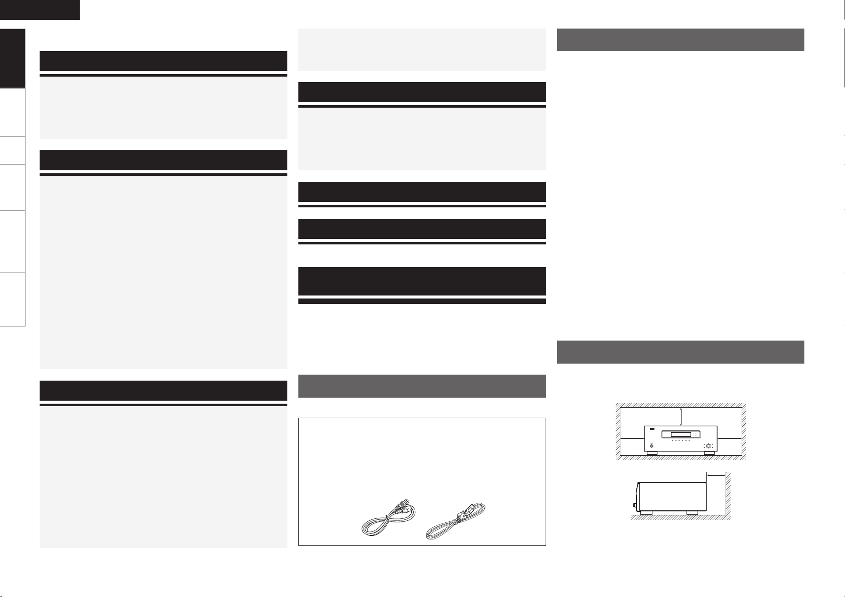
Accessories
Check that the following parts are supplied with the product.
q Owner’s manual ...................................................................... 1
w Warranty (for North America model only) ................................ 1
e Service station list ...................................................................1
r Power cord .............................................................................. 1
Cord length:qModelle für die Nordamerika: .........6.6 ft / 2.0 m
wEurope model: ................................ 5.2 ft / 1.6 m
Cautions on Handling
• Before turning the ON/STANDBY switch on
Check once again that all connections are correct and that there are
no problems with the connection cables.
•
Power is supplied to some of the circuitry even when the unit is
set to the standby mode. When traveling or leaving home for long
periods of time, be sure to unplug the power cord from the power
outlet.
• About condensation
If there is a major difference in temperature between the inside of
the unit and the surroundings, condensation (dew) may form on
the operating parts inside the unit, causing the unit not to operate
properly.
If this happens, let the unit sit for an hour or two with the power
turned off and wait until there is little difference in temperature
before using the unit.
• Cautions on using mobile phones
Using a mobile phone near this unit may result in noise. If so, move
the mobile phone away from this unit when it is in use.
• Moving the unit
Turn off the power and unplug the power cord from the power
outlet.
Next, disconnect the connection cables to other system units before
moving the unit.
•
Note that the illustrations in these instructions may differ from the
actual unit for explanation purposes.
Cautions on Installation
Note:
For proper heat dispersal, do not install this unit in a confined
space, such as a bookcase or similar enclosure.
b Note
b
b
b
Wall
w e
e
-
q
t oiuy
q r
Q0
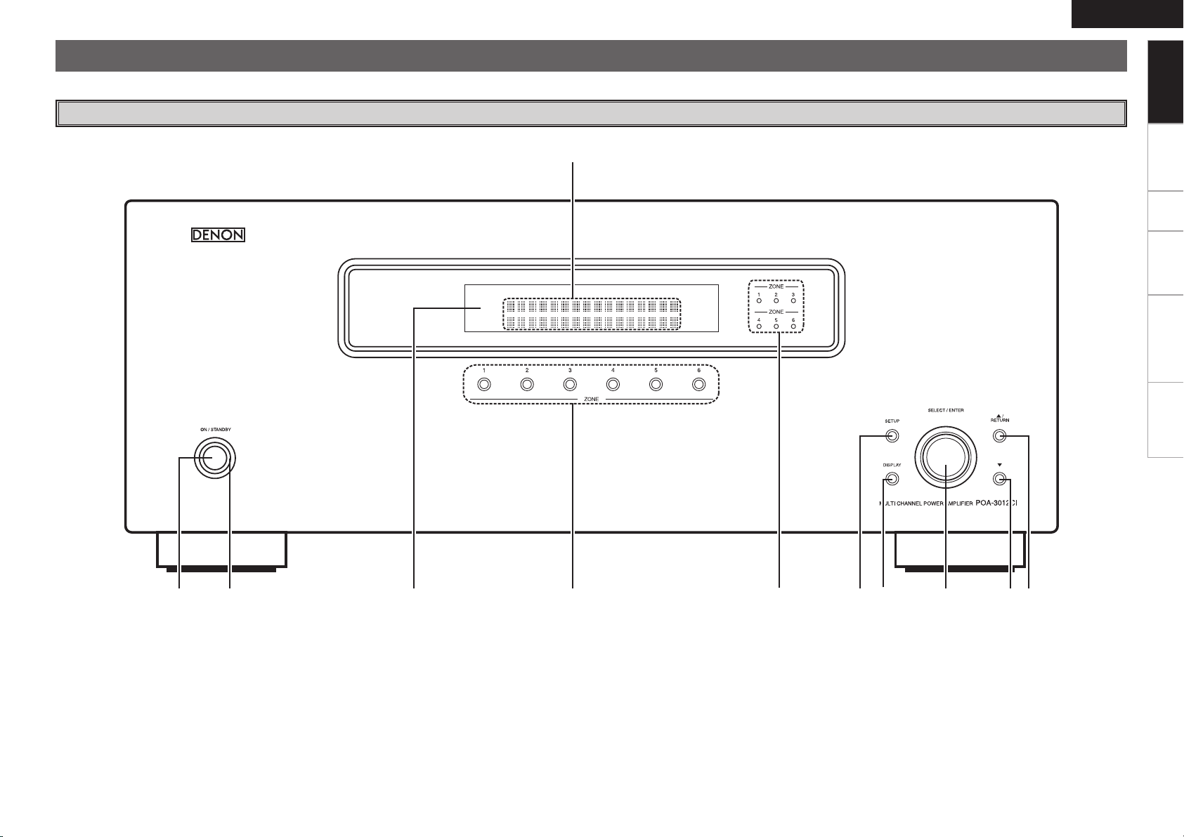
Part Names and Functions
For buttons not explained here, see the page indicated in parentheses ( ).
ENGLISH
Getting Started
Front Panel
Connections Setup Operations Troubleshooting
Specifications
q Power operation button
(ON / STANDBY) ·········································
w Power indicator ··········································· (17)
e Display ························································· (17)
q Information display
Displays present status information and Setup
menu etc.,
r ZONE select buttons ·································· (10)
(17)
t ZONE operation mode indicators ········· (6, 13)
y SETUP button ············································· (10)
u DISPLAY button ·········································· (17)
i SELECT / ENTER knob ······························· (10)
o i (Down) button ········································ (10)
Q0 u (Up) / RETURN button ··························· (10)
ENGLISH
tyuioQ0
wq e r
Getting Started
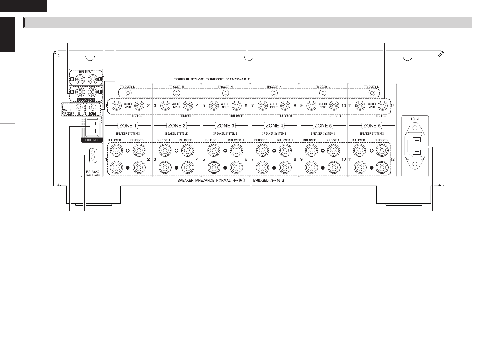
Rear Panel
Connections Setup Operations Troubleshooting
Specifications
q ETHERNET connector ··································· (8)
w RS-232C connector ······································· (9)
e Speaker terminals
(SPEAKER SYSTEMS) ··································· (5)
r AC inlet (AC IN) ··········································· (10)
t AUDIO INPUT connectors ···························· (7)
y TRIGGER IN jacks ·········································(9)
u MASTER TRIGGER OUT jack ························ (9)
i BUS INPUT connectors ································ (7)
o BUS OUTPUT connectors ···························· (7)
Q0 MASTER TRIGGER IN jack ···························· (9)
R
L
R
L
Connections
ENGLISH
Getting Started Setup Operations
Connections for all compatible audio signal formats are described
in this owner’s manual. Please select the types of connections
suited for the equipment you are connecting.
With some types of connections, certain settings must be made
on the POA-3012CI. For details, refer to the instructions for the
respective connection items below.
NOTE
• Do not plug in the power cord until all connections have been
completed.
• When making connections, also refer to the operating instructions of
the other components.
• In the case of Bus input / output connections, be sure to connect the
left and right channels properly (left with left, right with right).
• Do not bundle power cords together with connection cables. Doing
so can result in humming or noise.
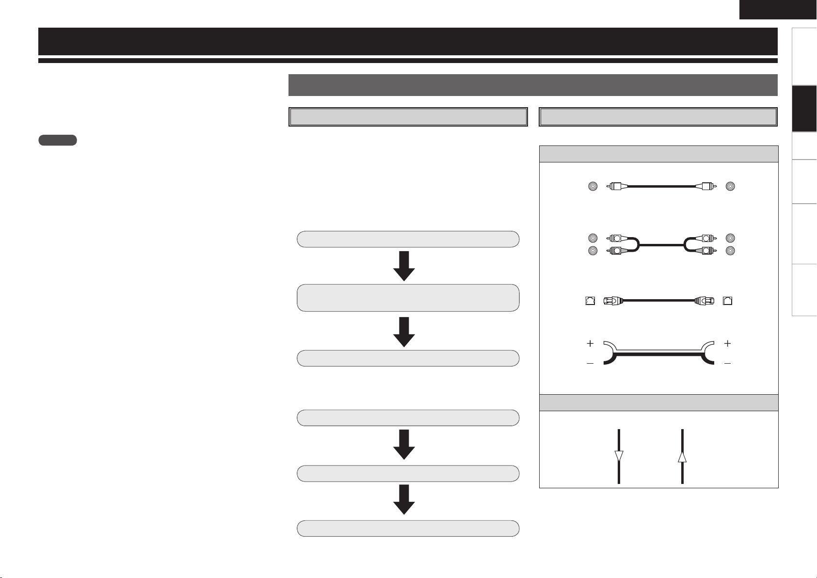
Preparations
Before Connecting
ZONE1 to ZONE6.
The same audio signal can be output from all ZONE or separate
signals can be output from each ZONE. The POA-3012CI also supports
BRIDGED output.
Before making the connections, determine the input signals and
output signals for each ZONE and then set up the POA-3012CI in
accordance with the following procedure.
n Input Setting
Select the input terminal to use.
Each Zone input connectors or
BUS input connectors.
Connect the external device to the input
terminal.
“INPUT SELECT” (vpage 13)
Set the input source.
“Input Connection” (vpage 7)
Cables Used for Connections
Select the cables according to the equipment being connected.The POA-3012CI incorporates six sets of 2-channel amplifier from
Audio cables
Audio input connections
(Black)
Pin-plug cable
Businput/output connections (stereo)
(Black)
(Black)
Stereo pin-plug cable
Network connections
Ethernet cable
Speaker connections
Speaker cable
Connections
Troubleshooting
Specifications
n Output Setting
Select the speaker output method.
NORMAL output or BRIDGED
output.
Signal direction
Audio signal:
Output
Input
Connect the speaker cable.
“Speaker Connections”
(vpage 5)
Input
Output
Set the output channel.
“OPERATION MODE”
(vpage 13)
 Loading...