

Denon DVD-955, DVD-2910, DVD-3910 Service Bulletin

100 Corporate Drive Mahwah, NJ 07430
Service Bulletin
No. : OST-901
Date:
May 31, 2007
_____________________________________________________________
Model: DVD-955, DVD-2910, DVD-3910
Subject: Countermeasure for a malfunction when a JVC® REAR
PROJECTOR is connected to the above models via the HDMI.
Symptom: When the above models are connected to JVC® REAR
PROJECTOR (model AV-48P575/56P575) via the HDMI, the Image signal is
interrupted for approximately two second intervals.
Solution:
the Pick-up of the DDC communication line. The voltage drop at the Pick-up
resistance section is reduced and the "H" signal level is increased up to 3.4V.
MODIFICATION: (Only Upon Claim) Please apply the following modification to
your customer's unit only when the above malfunction has been reported.
The units to which the modification is applied.
DVD-2910 and 955: GU-3615-2
HDMI Unit DVD-3910: GU-3613-3 HDMI Unit
Modification Procedures:
1) Removing the HDMI Unit:
• DVD-2910 and DVD-955: Remove the GU-3615-2 HDMI Unit from the Main
Unit according to the pages from 4 to 6 in the Service Manual (X-0203).
• DVD-3910: Remove the GU-3613-3 HDMI Unit from the Main Unit according to
the pages from 5 to 7 in the Service Manual (X- 0200).
As a countermeasure, change resistors to lower the resistance for
______________________________________________________________________________________
The information contained in this document is intended for the exclusive use by DENON Authorized Service Centers and their
employees. This document may contain information that is privileged, confidential and may be protected from disclosure under
applicable laws and terms of the DENON Service Agreement. Any distribution, disclosure, dissemination or copying of this
document and the information it contains is prohibited. No responsibility will be accepted by DENON for any damage, injury or loss
resulting from the misuse of the information contained in this document.
CONFIDENTIALITY NOTICE:
2) Replacement of resistors:
• DVD-2910, DVD-955 and DVD-3910: Please refer to the reference number in
the circuit diagram and exchange four chip type resistors each other.
Note: You have to remove the P. W. Board since all the four resistors have been
attached on the bottom side.
3) Install the HDMI Unit on the Main unit.
• DVD-2910 and DVD-955: Install the HDMI Unit on the Main Unit in the counter
procedures of the item #1), according to the pages from 4 to 6 in the Service
Manual (X-0203).
• DVD-3910: Install the HDMI Unit on the Main Unit in the counter procedures of
the item #1), according to the pages from 5 to 7 in the Service Manual (X-0200).
4) Confirmation of operation:
Connect the modified unit to a Display Unit that is equipped with the input
terminal of the HDMI or the DVI that is conformable to HDMI, and confirm the
image signal of the HDMI Output.
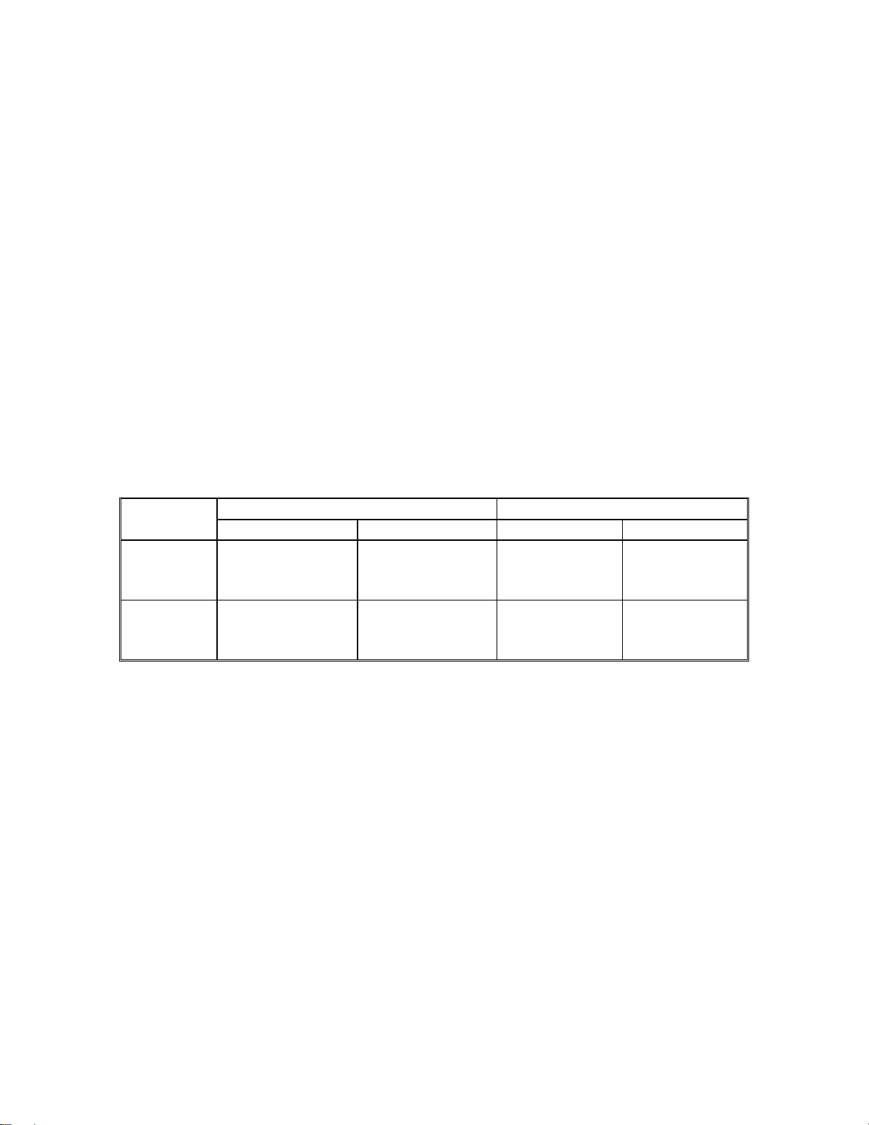
Parts:
FORMER NEW Ref #
Description Part Number Description Part Number
R133 &
134
R129 &
130
RM73B--
473JT+1608,
47kΩ
RM73B--
103JT+1608,
10kΩ
00D 247 2011
942
00D 247 2009
983
RM73B--
103JT+1608,
10kΩ
RM73B--
473JT+1608,
47kΩ
00D 247 2009
983
00D 247 2011
942
Serial Number Range:
DVD-2910 (Black) ~ 6609200
DVD-2910 (Silver) ~ 6601100
DVD-3910 (Black) ~ 8407550
DVD-3910 (Silver) ~ 8401300
______________________________________________________________________________________
The information contained in this document is intended for the exclusive use by DENON Authorized Service Centers and their
employees. This document may contain information that is privileged, confidential and may be protected from disclosure under
applicable laws and terms of the DENON Service Agreement. Any distribution, disclosure, dissemination or copying of this
document and the information it contains is prohibited. No responsibility will be accepted by DENON for any damage, injury or loss
resulting from the misuse of the information contained in this document.
CONFIDENTIALITY NOTICE:
 Loading...