

SERVO-CONTROLLED DIRECT DRIVE RECORD PLAYER
SERVICE MANUAL
DENON
Hi Fi Component/Record Player
| TABLE OF CONIENIS | |
|---|---|
| FEATURES | 1 |
| NAMES OF PARTS AND FUNCTION | 2 |
| ADJUSTMENT | 3 |
| TO CHANGE THE OPERATIONAL VOLTAGES | 4 |
| PARTS LIST OF KU-385 MOTOR SERVO AMP UNIT | 5 |
| PARTS LIST OF KU-356 ARM SERVO AMP UNIT | 6 |
| PARTS LIST OF KU-390 SWITCH UNIT | 6 |
| PARTS LIST OF PS-152 AND PS-155 FUSE UNITS | 6 |
| PARTS LIST OF PS-149 AND PS-153 POWER UNITS | 6 |
| LEAD CONNECTION OF SEMICONDUCTORS | 7 |
| EXPLODED VIEW OF TONEARM | 8 |
| PACKING INSTRUCTION | 8 |
| CIRCUIT DIAGRAM | 9 |
| PRINTED CIRCUIT BOARD | 10 |
| EXPLODED VIEW OF MAIN PARTS | 11 |
| DARTS LIST OF FYPLODED VIEW | 12 |
| 13 |
ΜΑΙΝ ΟΓΕΟΙΓΙΟΑ ΠΟΝΟ .
•
- 1 -
FEATURES
1. Low mass type tonearm improves trackability and fidelity.
The head shell is integrated into the arm tube, with its a connector portion located at the base of the tube. The construction materials for this tonearm have been selected very carefully to reduce the effective mass to the bare minimum. As a result, even when mated with a high compliance cartridge, the low end resonance frequency (f0) does not become too low but remains optimum. Clearer sound is achieved since the effects of record warpage and rotational excentricity are eliminated along with intermodulation distortion.
Since a straight shaped tonearm is almost symmetrical from side to side, dimensional or mechanical accuracies are improved. This design eliminates dimensional error or tortional distortion, making higher fidelity reproduction possible.
2. Replaceable S-shaped arm tube with standard 4P
Auto-lift mechanism with non-contact record-end sensor.
The automatic arm lift (auto-lift) mechanism functions in such a way that when a record playback is finished, the tonearm is automatically lifted and the platter rotation stops. This eliminates the possibility of stylus wear by leaving it tracking the lead out record grooves. At the end of play, a non-contact record-end sensor senses the velocity change of the tonearm with an opto-electronic transducer, eliminating unnecessary load on the record or stylus. Sound quality is totally unaffected by this system.
5. Angular control motor lifts tonearm.
The arm lifting device employs a servo-controlled angular control motor developed by DENON , for ultra-smooth and silent up and down motion.
6. PLL servo control via a quarts crystal oscillator guarantees speed accuracy of below 0.002%, and is almost totally immune to variation of temperature, humidity, load condition or supply voltage fluctuation.
connector.
By replacing the low mass arm tube with the S-shape arm tube, the virtually all head shells or integrated cartridges/ head shells can be utilized on the DP-60L. By having the ability to use the widest selection of cartridges, your audio enjoyment will be significantly broadened.
3. Magnetic recording speed detection system.
The turntable platter speed of the DP-60L is detected by DENON's magnetic recording detection system. The detection frequency is high enough (1000 pulses per rotation) to allow ultra fast response of the servo loop. Overshoot and wow and flutter are virtually eliminated.
7. The combination of Bi-directional servo control and electronic braking, together with rotational detection offers the quickest, smoothest start, stop and speed change-over.
8. Counterweight shaft is damped effectively to supress partial resonance of tonearm body.
9. The turntable mat was developed through vibration analysis through laser holography.
•
1) Power switch
The power is turned on when the switch is pressed in (....). The lamps in the stop button and in the strobe viewing window will light. When pressed again (.....), the power is turned off and lamps also turn off.
If the power switch is turned on (____) while the arm lifter is down, the arm lifter will lift.
2 Start buttons
Press
33 for a 33-1/3 rpm record, and
45 for a 45 rpm. record.
When one of the buttons is pressed, the lamp in the button lights and the platter starts rotation. Simultaneously, the arm lifter lowers.
NOTE 2:
If the start button is pressed right after the stop button is pressed, the lamp in the stop button may light and the platter will stop. Therefore, when changing speed during rotation, it is advisable to press the start button of either "33" or "45" directly without pressing the stop button.
(4) Strobe viewing window
When the platter is rotating at a specified speed, the strobe pattern observed through this window should appear to be standing still.
(5) Lifter button
Each time this button is pressed, the arm lifter moves up and down.
3 Stop button
When this button is pressed, the arm lifter lifts and then, after a few moments, the lamp in either the "33" or "45" buttons turns off. The lamp in the stop button will then light and the platter will stop.
NOTE 1:
10
The reason why the stop button lamp lights only after a brief delay is as follows. When the stop button is pressed, the arm lifter starts lifting immediately. However, since there is a small gap between the arm lifter and the arm tube, a time lag exists until the stylus leaves the disc. This record player is designed so that normal speed is maintained during this period before the platter stops.
6 Cueing lamp
- 2 --
This lamp lights while the arm lifter is down. 7 Counterweight
Turning this weight adjusts the traking force. 8 Anti-skating knob
By adjusting this knob, a force is applied towards the outside of the disc at the stylus tip.
ADJUSTMENT
Adjustment of spacing between detection head and 1. platter:
Adjust the spacing so that it may represent abt. 0.15 mm between the magnet-coated surface of platter and detection head. Depending upon the degree of the spacing, the condition of stop will vary. Consequently, adjustment should be made in such a way that the platter without the turntable sheet on glides slightly forward when stopping.
NOTE:
When the magnetic head is replaced, make sure that the terminal connection is as shown in the figure below. Otherwise, the platter may turn reversely.
(Reference)
Following are the waveforms of test points 39-40 and 41-40: (Test Point 40 is grownd.)

4. Arm lifter height adjustment:
Arm lifter is so designed as to move upward and downward together with the arm when its height is adjusted. Although the adjustment is carried out in the plant before shipment, if re-adjustment is required, the height can be re-adjusted in the following manner:
Confirming the regulator voltage: 2.
Since the power source employs a fixed voltage 3terminal IC, confirm that the output voltage of IC5 and represents 5V±0.2V. (No adjustment is feasible.)
-
RPM Adjustment:
3.
- (1) Pull out the lead wire through test points 39 and 41 (3P connecting pin) on motor servo P.C. Board KU-385 and connect 39 to positive side of the oscilloscope while 41, earth side.
- (2) Adjust the speed to 45 RPM; observing the waveform by means of an oscilloscope, Adjust VR2 so that the pulse may occur at the 40% position from the left of the pulse side of the half-cycle in a cycle of a square wave as shown in the figures below.
- (3) Subsequently adjust VR1 for 33 RPM in the same manner as in the case of 45 RPM so that the
- (1) Loosen the arm lifter height adjusting screws Depress lifter button to light the cueing lamp and lower the arm lifter.
- (2) Place the stylus point on the record surface and adjust the clearance between the arm lifter and arm tube to be 0.5~1.0 mm by moving the arm lifter vertically, and then tighten the height adjusting screw.
Arm lifter height adjusting screw
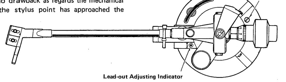
End adjustment (lead-out adjustment): 5.
The end adjustment has been carried out in the plant prior to shipment with respect to the straight arm tube. If, however, re-adjustment is required, adjust in the following manner:
pulse may be positioned at 40% of the square wave cycle.

Turn the anti-skating knob to '0'. (1)
- 3 -
- (2) Confirm that the cueing lamp is off. If it is lit, depress the lifter button so that the arm lifter is kept up.
- Set the cartridge stylus point to position 53 mm (3) from the motor shaft by the use of accessory overhang gauge.
- (4) Turn the lead-out adjusting screw with a screwdriver so as to allow the lead-out adjusting indicator to light.
NOTE 1.
If the auto-lift operates normally, there is no necessity for re-adjustment even if the lead-out adjusting indicator fails to light when the stylus point is set in a 53 mm position from the motor shaft.
NOTE 2.
Although the lead-out adjusting indicator may light on or off immediately before the end of the 17 cm disc performance, there is no drawback as regards the mechanical performance since the stylus point has approached the 53mm area.
6. Offset Adjustment:
(Adjust when IC1 (KU-356) is replaced.)
- (1) Make a short circuit between the both ends of R46 of arm servo P.C. board KU-356, between TR6 base and earth, and between TR9 base and earth.
- (2) Adjust VR1 so that the d.c. voltage at terminal 14 of IC1 may represent 1.4±0.1V.
Lead-out Adjusting Screw
TO CHANGE THE OPERATIONAL VOLTAGES
A. Model whose voltage selector is accessible by the user: (Multi-voltage model)
This equipment has been preset for a line voltage of 220V. Before inserting the power plug, please check if this voltage corresponds with the line voltage in your area. If it does not, be sure to adjust the voltage selector switch to the proper setting before operating this equipment. The voltage selector switch is located on the base surface below the turntable platter. Simply insert a screw driver into the voltage selector switch and turn it in either direction so that the desired voltage marked on the switch is positioned in the window.
Damage of equipment because of missetting of voltage selector is not within the limit of DENON liability.

Set the voltage selector in accordance with the nominal power supply voltage as shown in the table.
|
ACTUAL (nominal)
VOLTAGE (volt) |
VOLTAGE SETTING |
|---|---|
|
110
115 120 |
120 |
| 200 | 200 |
|
210
220 |
220 |
|
230
240 |
240 |
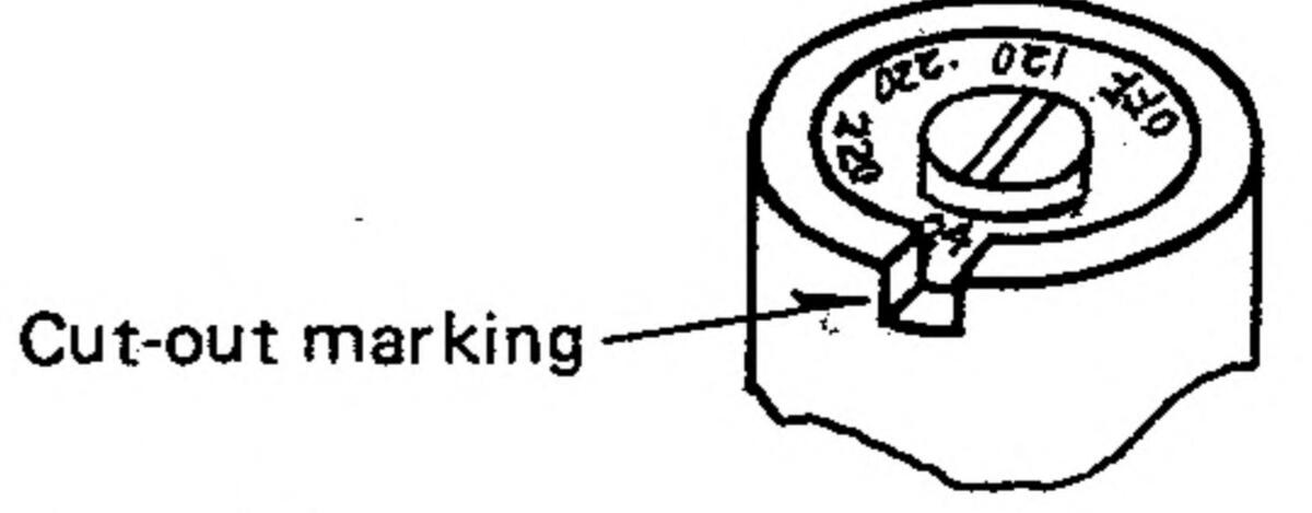
- B. Models whose voltage selector is not accessible by the user: (Australian, UK and Canadian models)
- 1 Australian and UK models
Although these models are provided with the voltage selector being preset to 240V, it cannot be operated by the user since it is blinded by the shield cover. However, in case the change of voltage setting is necessary, insert a screw driver into the voltage selector and turn it in either direction so that the desired voltage indicated on the selector is positioned at the cut-out marking as shown in figure below.
Voltage set at 220 V
51
Voitage Selector Switch
2 Canadian model
Although this model is provided with the voltage selector being preset to 120V, it cannot be operated by the user since it is blinded by the shield cover. Since the Canadian model must comply with the CSA standards, the components directly connected to the power line are CSA recognized having 125VAC rating. Therefore, DO NOT change the voltage setting.
PARTS LIST
.
.
-
•
KU-385 MOTOR SERVO AMP UNIT
| Ref. No. | Part. No. | Part Name | Remark | Ref. No. | Part. No. | Part Name | Remark | ||
|---|---|---|---|---|---|---|---|---|---|
| SEMI CONDU | JCTOR GROU | P | R62 | 2410761005 | RD14B2E684J | 680KΩJ 1/4W | |||
| ┝ | 0000100001 | 0001000 | T | R63,73 | 2410765001 | RD14B2E105J | 1MΩJ ¼W | ||
| IC3 | 2020180001 | SUSIZUA | Metal film | ||||||
| IC4 | 2630075005 | HA1/902P | R60 | 2452180000 | RN14K2E821F | 820ΩF ¼W | |||
| IC1, 2 | 2630094028 | TA7122BP (C) | R97 . | 2452199004 | RN14K2E472F | 4.7KΩF 1/4W | |||
| IC5 | 2680009005 | FS-7805M | R98 | 2452214002 | RN14K2E203F | 20KΩF 1/4W | |||
| IC7 | 2620089001 | HD7426P - | R61 | 2452221008 | BN14K2E393F | 39KOF 14W | |||
| TR7,12 | 2710100010 | 25A879 © (R) | R59 | 2452225004 | RN14K2E563E | 56KOF WA | |||
| TR8.11.15 | 2710113007 | 2SA999 (F) | • | THATAKZLOUUT | Matal aveda | ||||
| TR17 | 2720025004 | 2SB562 (C) | A | 976 04 | DCAADO AAA INIDI | ||||
| TR16 18 | 2720046009 | 2SB561 (C) | 2.2 | ||||||
| TD1~6 14 | 2720021043 | 250258 (0) | · | Variable resist | |||||
|
27002:0T0
070040200A |
VR1, 2 | EP-5462-13 | SOLID VOLUME | 10ΚΩΒ | |||||
| _ | CAPACITOR | GROUP | |||||||
| IK19 | 2/30111021 | r | |||||||
| D24,21 | 2/00280003 | KB154 | • | Electrolitic | |||||
| D23, 26 | 2750057029 | VO6E | C2, 7, 45 | 2544009002 | CE04W1A470= | 47µF 10∨ | |||
| ſ | D1~22, | 2760049008 | 1S2076 | C4, 5, 9, 10, | 2544015009 | CE04W1C100= | 10µF 16 | ||
| 41~44 | 17 | ||||||||
| D29~32 | 2760291005 | V06A | C28 | 2544054002 | CE04W1C220= | 220F 16 | |||
| D45 | 2760002003 | 1N60 | C27 20 | 2544012006 | CE041/10101- | ||||
| 1 | D37~40 | 3939041001 | LN81RP (HL) | LED | 021,20 | 254400000 | |||
| ļ | 2944086009 | CEU4W1E222= | 2,200µF 25 | ||||||
| RESISTOR G | ROUP | C1, 6, 22, 46 | 2544043000 | CE04W1HR47= | 0.47µF 50 | ||||
| Carbon film | C25, 26 | 2544044009 | CE04W1H010= | 1μF 50 | |||||
| 241000000 | DD110051001 | Film | |||||||
| R67, 69 | 2410200000 | RUI4BZEIUUJ | C18 | 2551062003 | CQ93M1H152K | 0.0015µF 50 | |||
| R105 | 2410270004 | RD1482E150J | 15ΩJ ¼W | C50 | 2551064001 | CQ93M1H222K | 0.0022µF 50 | ||
| R101, 102 | 2410280007 | RD14B2E390J | 39ΩJ ¼W | C14.15 | 2551070008 | CQ93M1H682K | 0.0068µF 50 | ||
| R66, 77 | 2410286001 | RD14B2E680J | 68ΩJ ¼W | C16 | 2551121038 | CO93M1H123K | 0.012uF 50 | ||
| R68,78,106 | 2410290000 | RD14B2E101J | 100ΩJ ¼W | C/0 /1 | 2551076002 | CO02M140222K | 0.022.5 | ||
| R85 | 2410300000 | RD14B2E271J | 270ΩJ 1/4W | 2001070002 | OCCOMMENTERS I | ο όπος π πο | |||
| B72 | 2410302008 | RD1482E331.I | 3300.1 %W | 2551122011 | COASINIHOPSI | 0.050µr 50 | |||
| 002~04 | 2410204006 | RD1482E2011 | 30001 1/1/1 | C19 | 2551084007 | CO93M1H104K | 0.1µ⊢ 50 | ||
| m92~94 | 2410304000 | • | • | Ceramic | |||||
| H86 | 2410300004 | RU 14BZE471J | 470365 7499 | C20,21,48,49 | 2531004007 | CK45B1H102K | 0.001µF 50 | ||
| R5, 13 | 2410308002 | RD1482E561J | 560ΩJ ¼W | C42~43 | 2531009002 | CK45B1H682K | 0.0068µF 50 | ||
| R88 | 2410314009 | RD14B2E102J | 1KΩJ %₩ | C23.24 | 2531024003 | CK45F1H103Z | 0.01µF 50 | ||
| R82~84 | 2410318005 | RD14B2E152J | 1.5KΩJ ¼W | C30 | 2531027000 | CK45F1H104Z | 0.1µF 50 | ||
| 1 | R18, 25, 32, | 2410322004 | RD14B2E222J | 2.2KΩJ ¼W | C11 12 | 2522610005 | 1705 50V | ||
| 41.42.64. | 200000 | CC403L11470J | |||||||
| 76 79 80 | · ( | A | DIFICULTU | ||||||
| /:\ | . UJJ | UTVELLAGOUSI | |||||||
| R19.23.24. | 2410326005 | RD14B2E332J | 3.3KΩJ ¼W | OTHER PAR | TS GROUP | • | |||
| 28 70 71 | 2228179203 | SERVO AMP P.C. | 3 | ||||||
| P20 45 48 | 2410328008 | RD1482F3921 | 3 9KOL 1/W | 4178020400 | HEATSINK | ||||
| n20,40,40, | 2410320000 | 0.01.320 /4** | 1170020400 | ES.7805M | |||||
| 044000000 | ٨ | A 12 A | |||||||
| К1, 9, 54, | 2410330009 | 4./ K36J % W | /· | ON. | |||||
| 58,89,90, | 2018007008 | ODINE | |||||||
| 91 | [ | 2050087026 | 2P WRAPPING | IRANS Pri. | |||||
| R6, 14 | 2410332007 | RD14B2E562J | 5.6KΩJ ¼W | TERMINAL | |||||
| R22 | 2410334005 | RD14B2E682J | 6.8KΩJ ¼W | 2050082047 | 4P WRAPPING | MAIN P.C.B | |||
| DD1102E1021 | 10K.O.I %W | TERMINAL | ↔ S.W P.C.B | ||||||
| R26, 39, 43. | 2410338001 | 6P WR APPING | 33/45. | ||||||
|
R26, 39, 43,
46, 47, 49 |
2410338001 | ND 1402L 1033 | 2058010008 | ||||||
|
R26, 39, 43,
46, 47, 49, 50, 52, 53 |
2410338001 | 2058010008 | TERMINAL | STOP LAMP | |||||
|
R26, 39, 43,
46, 47, 49, 50, 52, 53, |
2410338001 | 2058010008 |
TERMINAL
3P MINI CONNE |
STOP LAMP | |||||
|
R26, 39, 43,
46, 47, 49, 50, 52, 53, 55, 65, 75 |
2410338001 | 15KOL 1/1/ |
2058010008
2035622008 |
TERMINAL
3P MINI CONNE |
STOP LAMP
TEST POINT |
||||
|
R26, 39, 43,
46, 47, 49, 50, 52, 53, 55, 65, 75 R95, 96 |
2410338001
2410342000 |
RD14B2E1033
RD14B2E153J |
15KΩJ ¼W | 2058010008 |
TERMINAL
3P MINI CONNE PIN |
STOP LAMP
TEST POINT |
|||
|
R26, 39, 43,
46, 47, 49, 50, 52, 53, 55, 65, 75 R95, 96 R27 |
2410338001
2410342000 2410344008 |
RD14B2E103J
RD14B2E153J RD14B2E183J |
15ΚΩJ ¼W
18ΚΩJ ¼W |
2058010008
2035622008 FEP12802 |
TERMINAL
3P MINI CONNE PIN 3P MINI CONNE |
STOP LAMP
TEST POINT MOTOR |
|||
|
R26, 39, 43,
46, 47, 49, 50, 52, 53, 55, 65, 75 R95, 96 R27 R29, 35, 37, |
2410338001
2410342000 2410344008 2410346006 |
RD14B2E103J
RD14B2E153J RD14B2E183J RD14B2E223J |
15ΚΩJ ¼W
18ΚΩJ ¼W 22ΚΩJ ¼W |
2058010008
2035622008 FEP12802 |
TERMINAL
3P MINI CONNE PIN 3P MINI CONNE PIN |
STOP LAMP
TEST POINT MOTOR |
|||
|
R26, 39, 43,
46, 47, 49, 50, 52, 53, 55, 65, 75 R95, 96 R27 R29, 35, 37, R2, 7, 10, |
2410338001
2410342000 2410344008 2410346006 2410354001 |
RD14B2E103J
RD14B2E153J RD14B2E183J RD14B2E223J RD14B2E473J |
15KΩJ ¼W
18KΩJ ¼W 22KΩJ ¼W 47KΩJ ¼W |
2058010008
2035622008 FEP12802 FEP12803 |
TERMINAL
3P MINI CONNE PIN 3P MINI CONNE PIN 4P MINI CONNE |
STOP LAMP
TEST POINT MOTOR HEAD |
|||
|
R26, 39, 43,
46, 47, 49, 50, 52, 53, 55, 65, 75 R95, 96 R27 R29, 35, 37, R2, 7, 10, 15, 38, 103, 104 |
2410338001
2410342000 2410344008 2410346006 2410354001 |
RD14B2E103J
RD14B2E153J RD14B2E183J RD14B2E223J RD14B2E473J |
15ΚΩJ ¼W
18ΚΩJ ¼W 22ΚΩJ ¼W 47ΚΩJ ¼W |
2058010008
2035622008 FEP12802 FEP12803 |
TERMINAL
3P MINI CONNE PIN 3P MINI CONNE PIN 4P MINI CONNE PIN |
STOP LAMP
TEST POINT MOTOR HEAD |
|||
|
R26, 39, 43,
46, 47, 49, 50, 52, 53, 55, 65, 75 R95, 96 R27 R29, 35, 37, R2, 7, 10, 15, 38, 103, 104 R2 11 32 |
2410338001
2410342000 2410344008 2410346006 2410354001 |
RD14B2E1033
RD14B2E153J RD14B2E183J RD14B2E223J RD14B2E473J |
15ΚΩJ ¼W
18ΚΩJ ¼W 22ΚΩJ ¼W 47ΚΩJ ¼W |
2058010008
2035622008 FEP12802 FEP12803 |
TERMINAL
3P MINI CONNE PIN 3P MINI CONNE PIN 4P MINI CONNE PIN |
STOP LAMP
TEST POINT MOTOR HEAD |
|||
|
R26, 39, 43,
46, 47, 49, 50, 52, 53, 55, 65, 75 R95, 96 R27 R29, 35, 37, R2, 7, 10, 15, 38, 103, 104 R3, 11, 33, |
2410338001
2410342000 2410344008 2410346006 2410354001 2410362006 |
RD14B2E103J
RD14B2E153J RD14B2E183J RD14B2E223J RD14B2E473J RD14B2E104J |
15ΚΩJ ¼W
18ΚΩJ ¼W 22ΚΩJ ¼W 47ΚΩJ ¼W |
2058010008
2035622008 FEP12802 FEP12803 |
TERMINAL
3P MINI CONNE PIN 3P MINI CONNE PIN 4P MINI CONNE PIN |
STOP LAMP
TEST POINT MOTOR HEAD |
|||
|
R26, 39, 43,
46, 47, 49, 50, 52, 53, 55, 65, 75 R95, 96 R27 R29, 35, 37, R2, 7, 10, 15, 38, 103, 104 R3, 11, 33, 34, 40 |
2410338001
2410342000 2410344008 2410346006 2410354001 2410362006 |
RD14B2E1033
RD14B2E153J RD14B2E183J RD14B2E223J RD14B2E473J RD14B2E473J |
15ΚΩJ ¼W
18ΚΩJ ¼W 22ΚΩJ ¼W 47ΚΩJ ¼W |
2058010008
2035622008 FEP12802 FEP12803 |
TERMINAL
3P MINI CONNE PIN 3P MINI CONNE PIN 4P MINI CONNE PIN |
STOP LAMP
TEST POINT MOTOR HEAD |
|||
|
R26, 39, 43,
46, 47, 49, 50, 52, 53, 55, 65, 75 R95, 96 R27 R29, 35, 37, R2, 7, 10, 15, 38, 103, 104 R3, 11, 33, 34, 40 R36, 87 |
2410338001
2410342000 2410344008 2410346006 2410354001 2410362006 2410366002 |
RD14B2E1033
RD14B2E153J RD14B2E183J RD14B2E223J RD14B2E473J RD14B2E104J RD14B2E104J |
15ΚΩJ ¼W
18ΚΩJ ¼W 22ΚΩJ ¼W 47ΚΩJ ¼W 100ΚΩJ ¼W |
ŕ | WARNING |
2058010008
2035622008 FEP12802 FEP12803 |
TERMINAL
3P MINI CONNE PIN 3P MINI CONNE PIN 4P MINI CONNE PIN |
STOP LAMP
TEST POINT MOTOR HEAD |
|
|
R26, 39, 43,
46, 47, 49, 50, 52, 53, 55, 65, 75 R95, 96 R27 R29, 35, 37, R2, 7, 10, 15, 38, 103, 104 R3, 11, 33, 34, 40 R36, 87 R56 |
2410338001
2410342000 2410344008 2410346006 2410354001 2410362006 2410366002 2410370001 |
RD14B2E103J
RD14B2E153J RD14B2E183J RD14B2E223J RD14B2E473J RD14B2E473J RD14B2E104J RD14B2E154J RD14B2E224J |
15ΚΩJ ¼W
18ΚΩJ ¼W 22ΚΩJ ¼W 47ΚΩJ ¼W 100ΚΩJ ¼W 150KΩJ ¼W |
Ĺ | WARNING |
2058010008
2035622008 FEP12802 FEP12803 Shaded |
TERMINAL
3P MINI CONNE PIN 4P MINI CONNE PIN oarts are importa |
STOP LAMP
TEST POINT MOTOR HEAD |
|
|
R26, 39, 43,
46, 47, 49, 50, 52, 53, 55, 65, 75 R95, 96 R27 R29, 35, 37, R2, 7, 10, 15, 38, 103, 104 R3, 11, 33, 34, 40 R36, 87 R56 R4, 12, 57 |
2410338001
2410342000 2410344008 2410346006 2410354001 2410362006 2410366002 2410370001 2410378003 |
RD14B2E103J
RD14B2E153J RD14B2E183J RD14B2E223J RD14B2E473J RD14B2E473J RD14B2E104J RD14B2E154J RD14B2E224J RD14B2E224J RD14B2E474J |
15ΚΩJ ¼W
18ΚΩJ ¼W 22ΚΩJ ¼W 47ΚΩJ ¼W 100ΚΩJ ¼W 150ΚΩJ ¼W 220ΚΩJ ¼W |
Ĺ | WARNING |
2058010008
2035622008 FEP12802 FEP12803 Shaded Replace |
TERMINAL
3P MINI CONNE PIN 3P MINI CONNE PIN 4P MINI CONNE PIN oarts are important always with same |
STOP LAMP
TEST POINT MOTOR HEAD nt to SAFET ne type, sar |
| Davé Niamo | -1. | Ref. No. | Part No | Part Name | Remark | |||||
|---|---|---|---|---|---|---|---|---|---|---|
| Ret. No. | Part. NO. | Part Name | - Rema | rĸ | ||||||
| SEMI CONDU | JCTOR GROU | P | • 1 | R62 | 2410761005 | RD14B2E684J | 680KΩJ ¼ | W | ||
| IC3 | 2620186001 | SC3120A | R63,73 | 2410765001 | RD1482E105J | 1M2J 14 | W | |||
| iC4 | 2630075005 | HA17902P | 0450400000 | IVIE tal tilm | ||||||
| IC1.2 | 2630094028 | TA7122BP (C) | 2452180000 | DNIAKZEOZIE | ||||||
| IC5 | 2680009005 | FS-7805M | 2452199004 | RIVIAKZE472F | 4./KS2F /4 | |||||
| 107 | 2620089001 | HD7426P - |
HY8
DC1 |
2452214002 | RIVIAKZEZUSE | ZUKSZE 1/4 | ||||
| T27 12 | 271010010 | 25A879 @ (R) | 2452221008 | RN14K2E393F | SOKOF W | |||||
| TR8 11 15 | 2710113007 | 2SA999 (F) | ELENARY SERVICE AND | ' | H99 | 2492229004 | RN14KZE563F | DOKS6F 741 | vv ( | |
| TR17 | 2720025004 | 2SB562 (C) | A | |||||||
| TR16 18 | 2720046009 | 2SB561 (C) | ||||||||
| TR1~6 14 | 2730021043 | 2SC458 (D) | · | variable resi | stor | |||||
| TRAN 12 | 2730196004 | 2SC2023 (Z) | VH1, 2 | EP-5462-13 | SOLID VOLUME | ΙΟΚΩΒ | ||||
| TR19 | 2730111021 | 2SC1213 (C) | CAPACITOR | GROUP | ||||||
| FD24 27 | 2760280003 | RB154 | Electrolitic | |||||||
| m23 26 | 2760057029 | V06E | · C2 7 45 | 2544000002 | CE041414 A 470- | |||||
| D1~22 | 2760049008 | 1S2076 | Contraction and Contraction of the | CA 5 0 10 | 2544005002 | CE04W1A470- | ||||
| 41~44 | 17 | 20440.10009 | ιομι | |||||||
| D29~32 | 2760291005 | V06A | C22 | 2544054002 | CE0414/10220- | 77 - | ||||
| D45 | 2760002003 | 1N60 | 020 | 2544054002 | ||||||
| D37~40 | 3939041001 | LN81RP (HL) | LED | C21,23 | 2574010000 | 2200.5 | ||||
| C1 6 22 /6 | 2544042000 | |||||||||
| RESISTOR G | SROUP | 1 | C25 26 | 2544043000 | ||||||
| Carbon fil | m | 020,20 | 2044044009 | V V | ||||||
| R67, 69 | 2410266005 | RD14B2E100J | 10ΩJ | 1⁄4W | C18 | 2551062002 | C093M1H152K | 501/ | ||
| R105 | 2410270004 | RD14B2E150J | 15ΩJ | 1⁄4W | C50 | 2551064001 | CO93M1H222K | 0.001045 5 | ||
| R101, 102 | 2410280007 | RD14B2E390J | 39ΩJ | 1⁄4W | C14 15 | 2551070008 | CO93M1H682K | 0.0022m | 501 | |
| R66, 77 | 2410286001 | RD14B2E680J | 68ΩJ | 1/2W | C16 | 2551121038 | CO93M1H123K | 0.0120F | 501 | |
| R68,78,106 | 2410290000 | RD14B2E101J | 100ΩJ | 1⁄4W | C40 41 | 2551076002 | CO93M1H223K | 0.022µF | 50V | |
| R85 | 2410300000 | RD14B2E271J | 270ΩJ | 1/4W | C13 | 2551122011 | CO93M1H563. | 0.056µF | 50V | |
| R72 | 2410302008 | RD14B2E331J | 330ΩJ | 1/4 W | C19 | 2551084007 | CO93M1H104K | 0.1 u F | 50V | |
| R92~94 | 2410304006 | RD14B2E391J | 390ΩJ | 14W | 2001001007 | Ceramic | ||||
| R86 | 2410306004 | RD14B2E471J | 470ΩJ | 1⁄4W | C20 21 48 49 | 2531004007 | CK45B1H102K | 501/ | ||
| R5, 13 | 2410308002 | RD14B2E561J | 560ΩJ | 1⁄4W | CA2~43 | 2531009002 | CK45R1H682K | 0.0001#1 | 50V | |
| R88 | 2410314009 | RD14B2E102J | 1ΚΩͿ | 1⁄4W | C73 74 | 2531024003 | CK45F1H1037 | 501 | ||
| R82~84 | 2410318005 | RD14B2E152J | 1.5KΩJ | 1/4W | C30 | 2531027000 | CK45F1H1047 | 501 | ||
| R18, 25, 32, | 2410322004 | RD14B2E222J | 2.2KΩJ | 1/4W | C11 12 | 2522610005 | ||||
| 41, 42, 64, | 200000 | 004031114703 | Metalized Fi | ilm | ||||||
| 76, 79, 80, | : | ADE | DEERAIRADO | EQQ_2DAC2051 | RAF AC7 | |||||
| R19.23.24. | 2410326005 | RD14B2E332J | 3.3KΩJ | 1/4W | OTHER PAR | TS GROUP | • | |||
| 28, 70, 71 | 2228179203 | SERVO AMP P.C. | 3 | |||||||
| B20, 45, 48. | 2410328008 | RD14B2E392J | 3.9ΚΩJ | 1/4W | 4178020400 | HEAT SINK | ||||
| 51 | 4178050001 | HEAT SINK | FS-7805M | |||||||
| R1 9 54 | 2410330009 | RD14B2E472J | 4.7ΚΩJ | 1/2W | SK2 | FEP0429K | SPARK KILLER | |||
| 58 89 90 | دت | 2618007008 | CRYSTAL | 9MHz | ||||||
| a1 | 2050087026 | 2P WRAPPING | TRANS Pri | |||||||
| R6 14 | 2410332007 | RD1482E5621 | 5 6K O.I | 1/4W | TERMINAL | |||||
| B22 | 2410334005 | RD1482F6821 | 6.8K.0.1 | 1/4 W | 2050082047 | 4P WRAPPING | MAINPCE | 3 | ||
| R76 20 12 | 2410338001 | BD1482F1021 | 10001 | 1/W | TERMINAL | ↔ SWPCF | 3 | |||
| 16 17 10 | 2058010002 | 6P WRAPPING | 33/45 | |||||||
| 50,57,43, | 2000000000 | TERMINAL | STOP 1 AM | P | ||||||
| 50, 52, 55, | 2035622000 | TEST POIN | T | |||||||
| DO5 06 | 2410242000 | RD1482F1521 | 15601 | 1/1 M | 20022000 | |||||
|
n90,90
b07 |
2410244000 | RD14R7F1221 | 12801 | 1/1/W | EED12002 | 2D MAINI CONNE | MOTOP | |||
| D20 25 27 | 2410246006 | RD148252221 | 22801 | 1/1 M | FEFIZOUZ | DIN | 21 | |||
| D2710 | 24102540000 | RD1482E4721 | ATKOI | 1/4 W | EED12002 | |||||
|
n2, 7, 10,
15, 38, 102, 104 |
2410001 | /4 * * | FEF 12003 | TEAU | ||||||
| 103,104 | 2/10262006 | RD148251041 | 100101 | 1/.10/ | ||||||
| H3, 11, 33, | 2410302000 | IOOK32J | 74 V V | |||||||
| 34,40 | 2440266000 | 00140051541 | 1EOKOL | 1/.14/ | ||||||
| H30,8/ | 2410300002 | 100K36J | 1/ \N | WARNING | : Shaded | parts are importa | nt to SAFE | TY. | ||
| K56 | 24103/0001 | AZOKSAJ |
74 V V
1/ 1/1 |
Renlaco | alwave with car | ne tvne e | ame | |||
| H4, 12, 57 | 24103/8003 | FCOKSLJ |
74 V V
1/ 1 A 2 |
neplace | uivvuys vvitil sal | no cype, se | arno | |||
| R21 | 2410759004 | RU 1482E564J | DOUKSIJ | 74 V V | rating. |
.
.
:
PARTS LIST
1
• )
1
Э
KU-356 ARM SERVO AMP UNIT
| Ref. No. | Part No. | Part Name | Remarks | C6 7 20 |
|---|---|---|---|---|
| SEMI CONDU | JCTOR GROU | P | C3, 9, 10 | |
| 000070004 | LIA 1 70010 | ··· | 13, 14 | |
| 101,2 | 2030070004 | |||
| 2710141000 | 20A/00 | |||
| 2720040009 | ||||
| 1 H1~6 | 2730021043 | |||
| 1 R9, 10 | 2740038000 | 10076 | ||
| D1~4,6~9, | 2760049008 | 152070 | ||
| 12~15 | KU-390 | |||
| 17,19 | 0700010017 | 47042 | ||
| D18 | 2/00210017 | Ref. No. | ||
| 016 | 3939079002 | |||
| D5 | 3939023003 | |||
| 3939019101 | ||||
| RESISTOR C | ROUP | |||
| Carbon film | Í L . | |||
| R65.66 | 2412036000 | RD14B2E4R7J | 4.7ΩJ ¼W | |
| R46 | 2412038008 | RD14B2E5R6J | 5.6ΩJ ¼W | PS-152 |
| R24.47 | 2412052000 | RD14B2E220J | 22ΩJ 1/4W | |
| R60.61.64 | 2412056006 | RD14B2E330J | 33ΩJ ¼W | Ref No |
| R5.70 | 2412068007 | RD14B2E101J | 100ΩJ ¼W | |
| R1, 19 | 2412074004 | RD14B2E181J | 180ΩJ ¼W | |
| R41 69 71 | 2412078000 | RD14B2E271J | 270ΩJ ¼W | |
| R23 | 2412084007 | RD14B2E471J | 470ΩJ ¼W | |
| R62 63 | 2412088003 | RD14B2E681J | 680ΩJ ¼W | |
| R4 6 14 | 2412092002 | RD14B2E102J | 1KΩJ ¼W | |
| 27 40 42 | PS-155 | |||
| 53 59 | ||||
| R48 | 2412096008 | RD14B2E152J | 1.5KΩJ 1/4W | Ref No |
| R3 28 68 | 2412100004 | RD1482E222J | 2 2K Q. 1 1/W | |
| R50~52 56 | 2412102002 | RD14B2E272J | 2.7KQJ 1/2W | |
| RG 45 | 2412108006 | RD14B2E472J | 47KΩ. 1/2W | |
| BQ 32~34 | 2412116001 | RD1482F103J | 10KQ1 %W | |
| 20 22 20 | 27121100001 | |||
| P16 17 26 | 2412124006 | RD1482F223.L | 22K.O.1 1/W | |
| 21 25 27 | 2-1212-1000 | PS-149 P( | ||
| · | ||||
| P2 15 | 2412128002 | RD1482F333. | 33K01 1/W | Ref. No. |
| R67 | 2412132001 | RD1482F473. | 47K.0.1 %W | RESISTOR |
| R11 12 | 2412140006 | RD14B2E104J | 100KΩJ ¼W | |
| R43 44 | 2412142004 | RD1482E124J | 120KΩJ 1/4W | H4 |
| R7 | 2412146000 | RD14B2E184J | 180KΩJ 1/2W | CAPACITO |
| R13 | 2412148008 | RD14B2E224J | 220KΩJ ¼W | A 62 3 |
| R25 40 | 2412152007 | RD14B2E334J | 330K QJ 1/W | |
| R10 20 | 2412164008 | BD14B2E105J | 1MQJ 1/W | OTHER P |
| 26 54 57 | 2.1.2.0.000 | |||
| 00, 04, 07 | Metal film | |||
| B20 | 2452191002 | RN14K2E222F | 2.2KΩf ½W | |
| R18 | 2452202001 | RN14K2E622F | 6.2KΩF 1/4W | |
| Variable Resistor | ||||
| 2116000015 | V08PB103 | 10ΚΩΒ | • | |
| - PS-153 P | ||||
| CAPACITOR | GROUP | · | ||
| Electrolitic | Ref. No. | |||
| C12 | 2544003008 | CE04W0J101 | 100µF 6.3V | RESISTOR |
| C11 | 2544006005 | CE04W0J471 | 470µF 6.3∨ | |
| C21 | 2544009002 | CE04W1A470 = | 47μF 10V | R4 |
| C8 | 2544010004 | CE04W1A101 = | 100µF 10V | CAPACITO |
| C4 | 2549017002 | CE04=1C100= | 10µF 16V | |
| C2, 5 | 2544043000 | CE04W1HR47= | 0.47µF 50V | |
| 15, 16 | OTHER | |||
| C1, 19 | 2543014043 | CE04D1C220MBI | P 22μF 16V | |
| Tantalum | ||||
| C17, 18 | 2541003001 | CS45E0J100M | 10µF 6.3V |
| Ref. No. | Part No. | Part Name | Remarks |
|---|---|---|---|
|
C6, 7, 20
C3, 9, 10 13, 14 |
2531026001
2531027000 |
CK45F1H473Z
CK45F1H104Z |
Ceramic
0.047µF 50∨ 0.1µF 50∨ |
| OTHER PA | RTS GROUP | ||
|
2228272100
2129059008 |
ARM SERVO AM
PUSH SWITCH |
IP P.C.B
LIFTER UP/Down |
KU-390 SWITCH UNIT
| Ref. No. | Part No. | Part Name | Remarks | |
|---|---|---|---|---|
| 2228265007 | SWITCH P.C. BO/ | SOARD | ||
| • | 2129059008 | PUSH SWITCH | ||
| 3930047033 | PILOT LAMP | GREEN | ||
| 3930047046 | PILOT LAMP | WHITE | ||
PS-152 FUSE UNIT
| Ref. No. | Part No. | Part Name | Remarks | |
|---|---|---|---|---|
|
2228374105
FEP1287 |
FUSE P.C.B. | |||
| 1 | 2061015029 | FUSE TOLDER | 1A 250V |
٠
PS-155 FUSE UNIT (Canadian model only)
| Ref. No. | Part No. | Part Name | Remarks | |
|---|---|---|---|---|
| Δ | 2228374105 | FUSE P.C.B. | ||
| 7 | EP-72663 | FUSE | | ∴ 1A 250V |
PS-149 POWER UNIT
| Ref. No. | Part No. | Part Name | Remarks |
|---|---|---|---|
| RESISTOR | GROUP | ||
| R4 | 2410163001 | RD14B2H121J | 120ΩJ ½₩ |
| CAPACITOR | GROUP | · | |
| C2, 3 | 2518001023 | CP05C==AC473MC | 0.047µF 450VAC |
| OTHER PAF | RTS GROUP | ||
|
2228356000
2398001007 2061036008 FEP1287 |
POWER SUPPLY P.C
LINE FILTER COIL FUSE FUSE HOLDER |
.B
630mA/250V |
PS-153 POWER UNIT (Canadian model only)
- 6 ---
| Ref. No. | Ref. No.Part No.RESISTOR_GROUPR42410163001CAPACITOR GROUP22,32568019010CTHER | Part Name | Remarks | ||
| RESISTOR | GROUP | Carbon film | |||
| R4 2410163001 | RD14B2H121J | 120ΩJ ½W | |||
| CAPACITOR | GROUP | •••••••••••••••••••••••••••••••••••••• | |||
| V | C2,3 | 2568019010 | CF93B2BAC473M | 0.047µF 125VAC | |
| OTHER | |||||
| Z | 2228356000 | POWER SUPPLY P.C. | B . | ||
| 7 | 2398001007 | LINE FILTER COIL | |||
| 7 | EP-/2061 | FUSE | 630mA/250V | ||
•
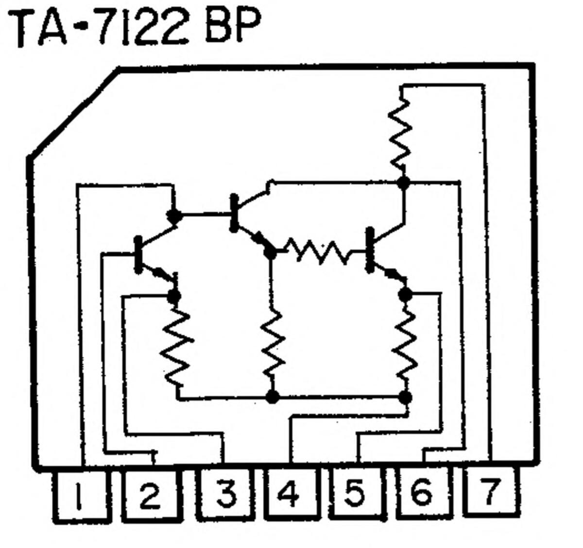
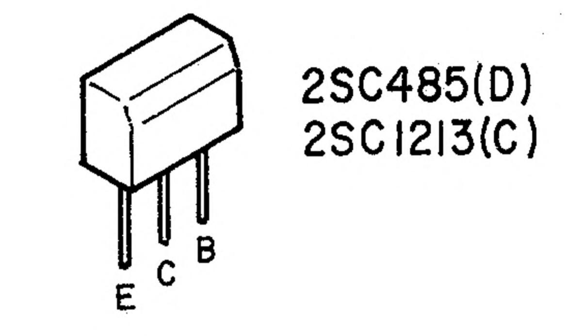
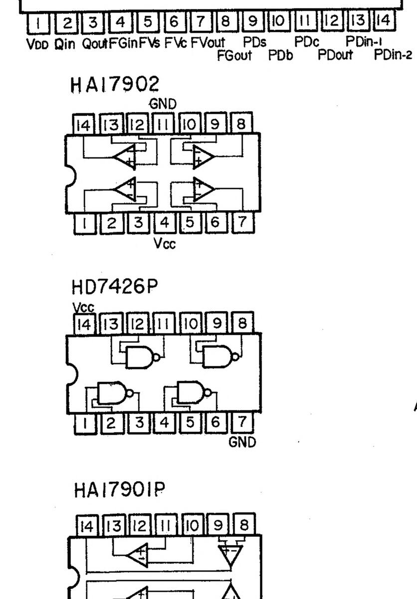
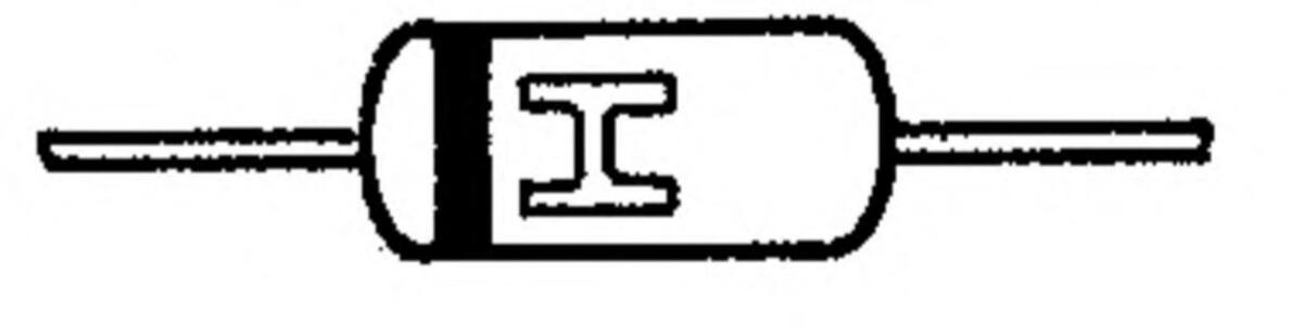
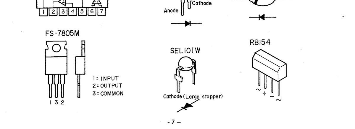
LEAD CONNECTION OF SEMICONDUCTORS

SC 3120A Vss Po Pi P2 P3 P4 P5 P6 P7 P8 P9 ST-2 20/27 28 27 26 25 24 23 22 21 20 19 18 17 16 15
TR
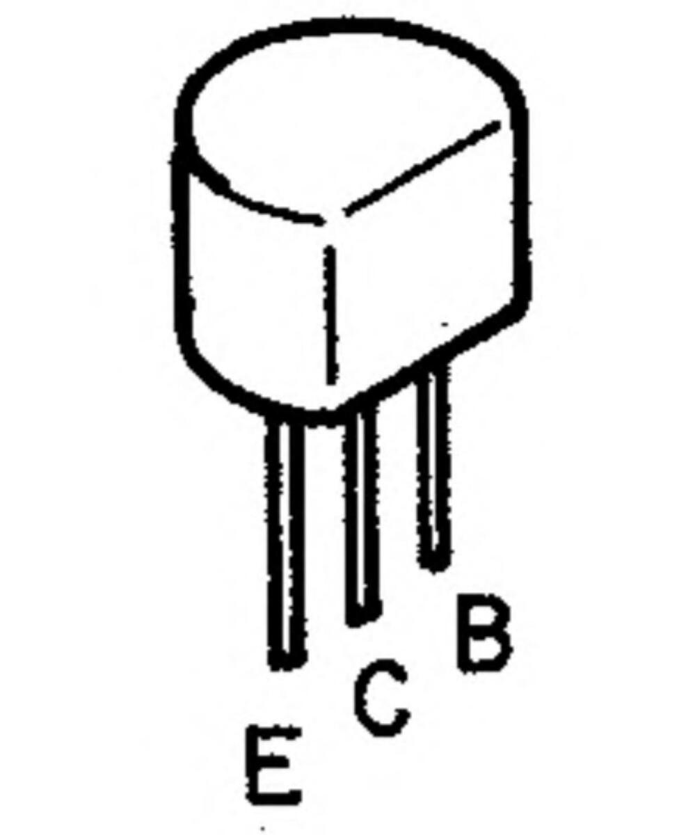
2SA879(R)© 2SA999(F) 2SB561(C) 2SB562(C) 2SD467(C)
Э
.......................................
2SA768 2SC2023Z
IN60 (Red) IS2076 (Light Blue)
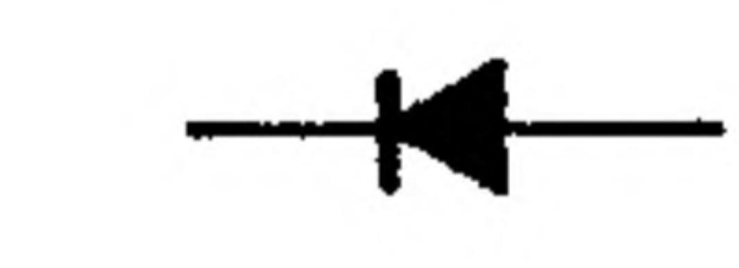

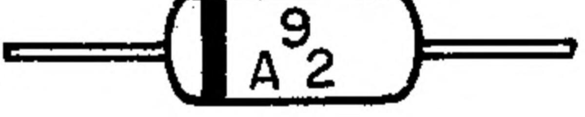


D
Anode
LN8IRP (HL)
LN222RP LN322GP
Cathode
EXPLODED VIEW OF TONEARM
• $
1
í.
•

.
| Ref. No. | Part No. | Part Name | R | Ref No. | Part No. | Part Name |
|---|---|---|---|---|---|---|
| . 1 | 3158389007 | PIPE ARM ASS. | 18 | 4248011103 | ADJUST CAM ASS'Y | |
| 2 | 3158429006 | MAIN BODY ASS. | 19 | 3158451003 | FRICTION WASHER | |
| 3 | 3158395004 | FINGER SCREW | 20 | 4761004008 | 4E RING | |
| 4 | 3158526006 | GUIDE PIN ASS. | 21 | 4740153016 | 2x6 CPTS | |
| 5 | 3158422100 | HOUSING ASS. | 22 | 4713303016 | 3x6 CBS | |
| 6 | 3158410109 | ARM REST ASS. | 23 | 3158162101 | SHAFT RING | |
| 7 | 4730304030 | 3x8 TAP SCREW | 24 | 4744203017 | 3x6 BSS(A) | |
| 8 | 4752003005 | 3SW | 25 | 3158402104 | WEIGHT SLEEVE ASS. | |
| 9 | 3158532003 | ARM BASE SUB ASS. | 26 | 3158530005 | WEIGHT RING ASS. | |
| 10 | 3158427105 | L.E.D. COVER | 27 | 3158414105 | PIPE ARM ASS. | |
| 11 | 3158063132 | LIFTER ARM ASS. | 28 | 3158417102 | WEIGHT SLEEVE ASS. | |
| 12 | 4744003013 | 3x3 SS(A) | 29 | 3158531004 | WEIGHT RING ASS. | |
| 13 | 3158428007 | LIFTER SHAFT | 30 | 3158424108 | SHAFT CASE | |
| 14 | 4638065109 | LIFTER SPRING | 31 | 4712303017 | 3x6 CFS | |
| 15 | 4761003009 | 3E RING | 32 | 4712304016 | 3x8 CFS | |
| 16 | 4751005004 | 4W | 33 | 4770132000 | 2.6x2 SPECIAL SCREW | |
| 17 | 4128215100 | SENSER BASE ASS'Y | 2 |
For a smooth function of the automatic arm lift of this model, a special grease (SILICONE GREASE G-31) is applied at the lifter shaft/cylinder bearing. In case of servicing this part, re-apply the SILICONE GREASE G-31 after cleaning the lifter shaft and inside of the cylinder.
After assembly, move the lifter shaft up and down until the movement thereof becomes smooth. Then make sure the lifter shaft falls by its own weight.
.
- 8 -
.
PACKING INSTRUCTION

| Ref. No. | Part No. | Part Name |
|---|---|---|
| 1 | 5028012105 | REAR PACKING ASS'Y |
| 2 | 5058093103 | PACKING ASS'Y |
| 3 | 5058092007 | LAMINATE ENVELOPE |
| 4 | 5028010103 | ACCESSORIES COVER |
| 5 | 5058006006 | ENVELOPE |
| 6 | 5298006002 | 45 ADAPTOR |
| 7 | 5298004004 | MINI DRIVER |
| 8 | 5298017208 | ADJ. GAUGE |
| 9 | 5058023018 | ENVELOPE |
| 10 | 5028011106 | BOTTOM PLATE |
| 11 | 5018159100 | CARTON CASE |
2
CIRCUIT DIAGRAM

- 9 -
1
•
لا

- 10 -
٠
•
•

-
•
•
______] _______ _____
81) x2 82 x2 83
84 103 x2 85 x4
) )x4
.
PARTS LIST OF EXPLODED VIEW
2
j.
1
2
}
| F | lef. No. | Part No. | Part Name | Remarks | Ref. No. | Part No. | Part Name | Remarks | |
|---|---|---|---|---|---|---|---|---|---|
| 1 | 4733309032 | 3×16 CBTS (1) | 55 | 1468120000 | DUST COVER ASS'Y | ||||
| 2 | 1058053118 | BOTTOM PLATE | 56 | KU-356 | LIFTER SWITCH | A part of | |||
| 3 | 4730406019 | 3×12 | P.C. Board | KU-356 | |||||
| 4 | EP-4772 | CORD HOLDER | 57 | 3939079002 | |||||
| 5 | 4733800010 | 3x8 CBTS | : . | 58 | 2129059008 | PUSH SWITCH | |||
| 6 | 4128212103 | GUIDE PLATE | 59 | 4018080108 | KNOB COSHION | ||||
| 7 | 4358014100 | CONNECTION PLATE | 61 | 1138103302 | • | ||||
| 8 | 4761001002 | 2 E-RING | 62 | 4490040209 | |||||
| 9 | 4218121104 | MOTOR ARM | 63 | 4700026005 | 3XO CRETCIM | ||||
| 10 | 4744200007 | 3x3 BSS | 64 | K11.300 | SWITCHLINIT | ||||
| 11 | 4730812001 | 3X8 CBIS | 65 | 3930047046 | PILOT LAMP (WHITE) | ||||
| 12 | 4128211104 | MOTOR BRACKET | 66 | 4498037102 | SW. HOLDER | ||||
| 13 | 21/8035109 | 67 | 4638009000 | 2F. COIL SPRING | |||||
| 14 | 4248010007 | 3E-BING | 68 | 1298014108 | BUTTON CUSHION | ||||
| 10 | 4701003005 | 3×6 CBS | 69 | 1138101100 | PUSH BUTTON | ||||
| 17 | 4770090058 | WASHER | 70 | 3930047033 | PILOT LAMP (GREEN) | ||||
| 18 | 4128209200 | CAM BASE ASS'Y | 71 | 4618067004 | PAD | ||||
| 19 | 3939019101 | CDS | ⚠ | 72 | 2178018210 | MOTOR | |||
| 20 | 3939023003 | LED (SEL 101W) | 73 | KU-385 | MOTOR SERVO | ||||
| 21 | 4118141103 | SHUTTER | 4400040000 | AMP UNIT | |||||
| 22 | 4418213003 | PUSH PLATE | 74 | 4498046009 | C.B.L. SUPPORT | ||||
| 23 | 4638212004 | SPRING | 76 | 4/53202009 | A maint af | ||||
| 24 | 4218115408 | SENSER HOLDER | 70 | NU-305 | P.C. BOARD |
A part of
KU-385 |
|||
| 25 | 4618087107 | SPACER | 77 | 3939041001 | LED | ||||
| 26 | 4418323100 | M. SHIELD PLATE | 78 | 4733800023 | 3x10 CBRTS | ||||
| 27 | 4713411018 | 4x25 CBS | 79 | 1468058208 | MIRROR CASE ASS. | ||||
| 28 | 4751005005 | 4W | 80 | 4498038004 | LED. HOLDER | ||||
| 29 | KU-356 | PHONE WIRE P.C. |
A Part of
KU-356 |
81 | 4770192008 | SPECIAL SCREW | |||
| 20 | 4128213005 | SHIELD BRACKET | 82 | 4620027003 | RUBBER BUSH | ||||
| 31 | 2098048030 | TERMINAL WIRE | 83 | 2339037205 | POWER TRANS | ||||
| 32 | 4730309019 | 3x16 CBRTS (1) | 84 | 4468076106 | MOTOR BOARD ASS'Y | ||||
| 33 | 4458024003 | CORD BUSH | 85 | 4/13406010 | 4x12 CBS | ||||
| -34 | 2039616007 | OUTPUT CORD | 80 | 4148022001 | |||||
| 35 | 2078007020 | LED SOCKET WITH WIR | E | 20100250001 | MACHETIC HEAD ACC | ||||
| 36 | 3939078003 | LED (LN222RP) | 00 | 11/0126004 | CHIELD PLATE | Multivoltage | |||
| 37 | 4128214208 | LED SUPPORTER | 03 | 4140120004 | SHLLDFLAIL | model | |||
| 38 | FPU-990 | TONE ARM UNIT | " | 4148102109 | SHIELD PLATE | Other models | |||
| 39 | 3158414105 | PIPE ARM ASS. | 90 | 4218074206 | RECORDED | • | |||
| 40 | 3158417102 | ASS | TURNTABLE | ||||||
| 11 | 3158531004 | WEIGHT RING ASS. | A | 91 | 4218094040 | ||||
| 42 | FPR0464-1 | DENON MARK | / | 32 | 2129130U28 | ||||
| 43 | 4498041004 | C.B. LOCKING | 02 | ΔΔ1QE20100 | PUSHSM RDACKET | ||||
| SUPPORT |
93
94 |
1138100101 | PUSH KNOR | ||||||
| 44 | FSC0102 | SPECIAL NUT (A) | 95 | 4618094006 | CUSHION | ||||
| 45 | 4418584004 | BUSHING PLATE (H) | 96 | 4638606005 | SPRING | ||||
| 46 | 4418551008 | BUSHING FLAIE (F) | Canadian model | 97 | KU-356 | ARM SERVO | |||
| 4418352007 | AMP UNIT | ||||||||
| 47 | MD-2982H | BUSHING | AUSTRIJAN MODEL | 98 | PS-155 | FUSE UNIT | Canadian model | ||
| N4D-38U2 | PS-152 | FUSE UNIT | Other models | ||||||
| 4400020000 | 99 | 2033902005 | PLUG ADAPTOR | Multi-voltage | |||||
| 48 | A | 100 | |||||||
| ••• | 2. | DC 140 | |||||||
| • | Other models | 101 | 4713203010 | 2.6x6 CBS | |||||
| ΛO |
100200200
101207000 |
HINGE | ٨ | 102 | 2123315010 | VOLTAGESETECTOR | |||
|
49
50 |
1048024403 | INSULATOR | حت | 103 | 4770031020 | 4x20 CBS (R) | |||
| 51 | 1018228200 | CABINET SUB ASS'Y | |||||||
| 52 | FTS0701 | HINGE PLATE | |||||||
| 53 | 4712404055 | 4x8 CFS | A WAR | NING: Sha | aded parts are importan | it to SAFETY. | |||
| 54 | 4628006107 | BUSHING | Re | place always with san | ne type, same | ||||
| ا ــــــــــــــــــــــــــــــــــــ |
| Ref. No. | Part No. | Part Name | Remarks | Ref. No. | Part No. | Part Name | Remarks | |
|---|---|---|---|---|---|---|---|---|
| 1 | 4733309032 | 3×16 CBTS (1) | 55 | 1468120000 | DUST COVER ASS'Y | |||
| 2 | 1058053118 | BOTTOM PLATE | 56 | KU-356 | LIFTER SWITCH | A part of | ||
| 3 | 4730406019 | 3×12 | E7 | 2020070002 | P.C. Board | KU-356 | ||
| 4 | EP-4772 | CORD HOLDER | 50 | 2120050002 | ||||
| 5 | 4733800010 | 3x8 CBIS | : . | 59 | 4618086108 | KNOR CUSHION | ||
| 6 | 4128212103 | GOIDE PLATE | 60 | 1138103302 | LIFT SW. KNOB | |||
| 7 | 4358014100 | 61 | 4498040209 | LIFT SW. HOLDER | ||||
| 8 | 4701001002 | MOTOR ARM | 62 | 4700010011 | 3x8 CPS W | |||
| 10 | 4744200007 | 3x3 BSS | 63 | 4700026005 | 3x8 CBRTS W | |||
| 11 | 4730812001 | 3x8 CBTS | 64 | KU-390 | SWITCH UNIT | |||
| 12 | 4128211104 | MOTOR BRACKET | 65 | 3930047046 | PILOT LAMP (WHITE) | |||
| 13 | 2178035109 | MOTOR (C) | 66 | 4498037102 | SW. HOLDER | |||
| 14 | 4248010007 | COM (A) | 67 | 4638009000 | 2F. COIL SPRING | |||
| 15 | 4761003009 | 3E-RING | 68 | 1298014108 | BUTTON CUSHION | |||
| 16 | 4713303016 | 3x6 CBS | 70 | 2020047022 | PUSH BUILUN | |||
| 17 | 4770090058 | WASHER | 71 | 4612067004 | ||||
| 18 | 4128209200 | CAM BASE ASS'Y | ٨ | 79 | 7172012710 | RANTAR | ||
| 19 | 3939019101 | 2.2 | 73 | KU-385 | MOTOR SERVO | |||
| 20 | 3939023003 | AMP UNIT | ||||||
| 21 | 4110141103 | 74 | 4498046009 | C.B.L. SUPPORT | ||||
| 22 | 4410213003 | SPRING | 75 | 4753202009 | 4-TW | |||
| 23 | 4218115408 | SENSER HOLDER | 76 | KU-385 | STOREBE LED | A part of | ||
| 25 | 4618087107 | SPACER | 77 | 20200/1001 | P.C. BUARD | KU-385. | ||
| 26 | 4418323100 | M. SHIELD PLATE | 78 | 47338041001 |
LED
3v10 CRRTS |
· · | ||
| 27 | 4713411018 | 4x25 CBS | 79 | 1468058208 | MIRROR CASE ASS | |||
| 28 | 4751005005 | 4W | 80 | 4498038004 | LED. HOLDER | |||
| 29 | KU-356 | PHONE WIRE P.C. | A Part of | 81 | 4770192008 | SPECIAL SCREW | ||
| 4400012005 | BOARD | KU-356 | 82 | 4620027003 | RUBBER BUSH | |||
| 30 | 202212005 | TERMINAL WIRE | 83 | 2339037205 | POWER TRANS | |||
| 32 | 4730309019 | 3x16 CBRTS (1) | 84 | 4468076106 | MOTOR BOARD ASS'Y | |||
| 33 | 4458024003 | CORD BUSH | 85 | 4713406010 | 4x12 CBS | · | ||
| -34 | 2039616007 | OUTPUT CORD | 80 | 4148022001 | BLIND | |||
| 35 | 2078007020 | LED SOCKET WITH WIF | E | 88 | 3918425004 | MAGNETIC HEAD ASS | ||
| 36 | 3939078003 | LED (LN222RP) | 89 | 4148126004 | SHIELD PLATE | Multi-voltage | ||
| 37 | 4128214208 | LED SUPPORTER | model | |||||
| 38 | FPU-990 | " | 4148102109 | SHIELD PLATE | Other models | |||
| 39 | 3158414105 | MEIGHT SLEEVE | 90 | 4218074206 | RECORDED | , | ||
| 40 | 3130417102 | ASS. | 01 | 1210001010 | DUBDED CHEET | |||
| 41 | 3158531004 | WEIGHT RING ASS. | A |
91
92 |
2129136028 | POWERSWITCH | ||
| 42 | FPR0464-1 | DENON MARK | 4 | •• | 2129136015 | POWER SWITCH | Other models | |
| 43 | 4498041004 | C.B. LOCKING | 93 | 4418532108 | PUSH SW: BRACKET | |||
| EC00100 | SPECIAL NILT (A) | 94 | 1138100101 | PUSH KNOB | ||||
| 44 | 111050102 | BUSHING PLATE (H) | 95 | 4618094006 | CUSHION | |||
|
40
A |
44100000 | BUSHING PLATE (F) | Canadian model | 96 | 4638606005 | SPRING | ||
| • | 4418552007 | BUSHING PLATE (G) | Other models | 97 | KU-356 | |||
| 1\ 47 | MD-2982H | BUSHING | Australian model | Δ | 02 | |||
|
,
,, |
NAD-3802 | BUSHING | Canadian model | PS-152 | FUSE UNIT | |||
| •• | 4450020005 | BUSHING | Other models | - | 99 | 2033902005 | PLUG ADAPTOR | Multi-voltage |
| • 48 | 2006019307 | AC POWER CORD | Australian model | model only | ||||
| •• | 2062019008 | ac power cord | Canadian model | 100 | PS-153 | POWER SUPPLY UNIT | Canadian model | |
| ••• | 2062026006 | AC POMER CORD | UK. model | PS-149 | POWER SUPPLY UNIT | Other models | ||
| 2062002031 | AC POWER CORD | Uther models | ٨ | 101 | 4/13203019 | 2.6x6 CBS | ||
| 49 | 4018027000 | HINGE | /:\ |
102
102 |
47700210010 | AYON CRC (D) | ||
| 50 | 1048024403 | CADINET CUD ACCA | 1770001020 | |||||
| 51 | TU18228200 | HINGE PLATE | ||||||
| 52 | 4712404055 | 4x8 CFS | A WAR | NING: Sha | aded parts are importar | nt to SAFETY. | ||
| 54 | 4628006107 | BUSHING | Re | place always with san | ne type, same | |||
- 12 -
rating.
· /
.
;
• • : : •
MAIN SPECIFICATIONS
Phono motor Direct drive AC motor Drive system: 33-1/3 rpm, 45 rpm. Speeds: 0.015% wrms (see note) Wow and flutter: More than 78dB (DIN-B) S/N: Less than 2.0 sec. (33-1/3 rpm) Rise time: Diecast aluminum 300 mm diam Mo- Platter: ment of inertia, 200 kg-cm2 (0.2Nm2) Including turntable mat AC servo motor Motor: Speed control system:
DENON
Speed servo control by frequency<br/>detection system combined with phase<br/>control system with reference to quartz<br/>crystal oscillator.Load influence:0% at out-most groove with stylus<br/>force of 100 g (0.98 N)Speed deviation:Less than 0.002%<br/>Electronic brake
Tonearm with vibration balance type Static Type: damping (Replaceable tonearm tube) 244 mm Effective length: 14 mm Overhang: Less than 2.5° Tracking error: Tracking force range: 0~2.5g/rot.(1 division is 0.1g) 0~25mN/rot. (1 division is 1mN) Acceptable weight of cartridge: Approx. 4g to 10g (Including screws and nuts when mounted on straight arm tube) Approx. 12g to 18g (Including head
NOTE:
Measured by DENON's method using magnetic pulse wheel.
• General
Power supply: Rated voltage and frequency are shown on the rating label at the back of cabinet and/or on the label attached to the power supply cord.
Power consumption:
Approx. 18 WDimensions:485Wx180Hx410D mm(Dust cover closed)Weight:Approx. 13 kg
* All specifications and outward appearance are subject to alteration for improvement without notice.
on S-shaped tonearm tube)
Head shell connector:
Standard type 4P (On S-shaped tonearm tube)
shell, screws and nuts when mounted
Arm height adj. range:
Approx. 5mmOutput cord:Low capacitance cordFacilities provided: Anti-skating device and Automatic arm<br/>lift mechanismTonearm lifter:Servo-controlled by angular control
motor
Change the rated frequency The DP-60L can be used compatibly on power supply frequencies of 50Hz and 60Hz.
NIPPON COLUMBIA CO., LTD.
No. 14-14, AKASAKA 4-CHOME MANATO-KU, TOKYO, JAPAN TEL: 03-584-8111 TELEX: JAPANOLA J22591 CABLE: NIPPON COLUMBIA TOKYO
81.1 Printed in Japan
7503-054


 Loading...