


Denon DHT-485DV Connection Guide
DISPLAY
TV ASPECT
4:3 LETTER BOX
STILL MODE AUTO
ANGLE ICON ON
AUTO POWER OFF ON
PROGRESSIVE OFF
PANEL DISPLAY BRIGHT
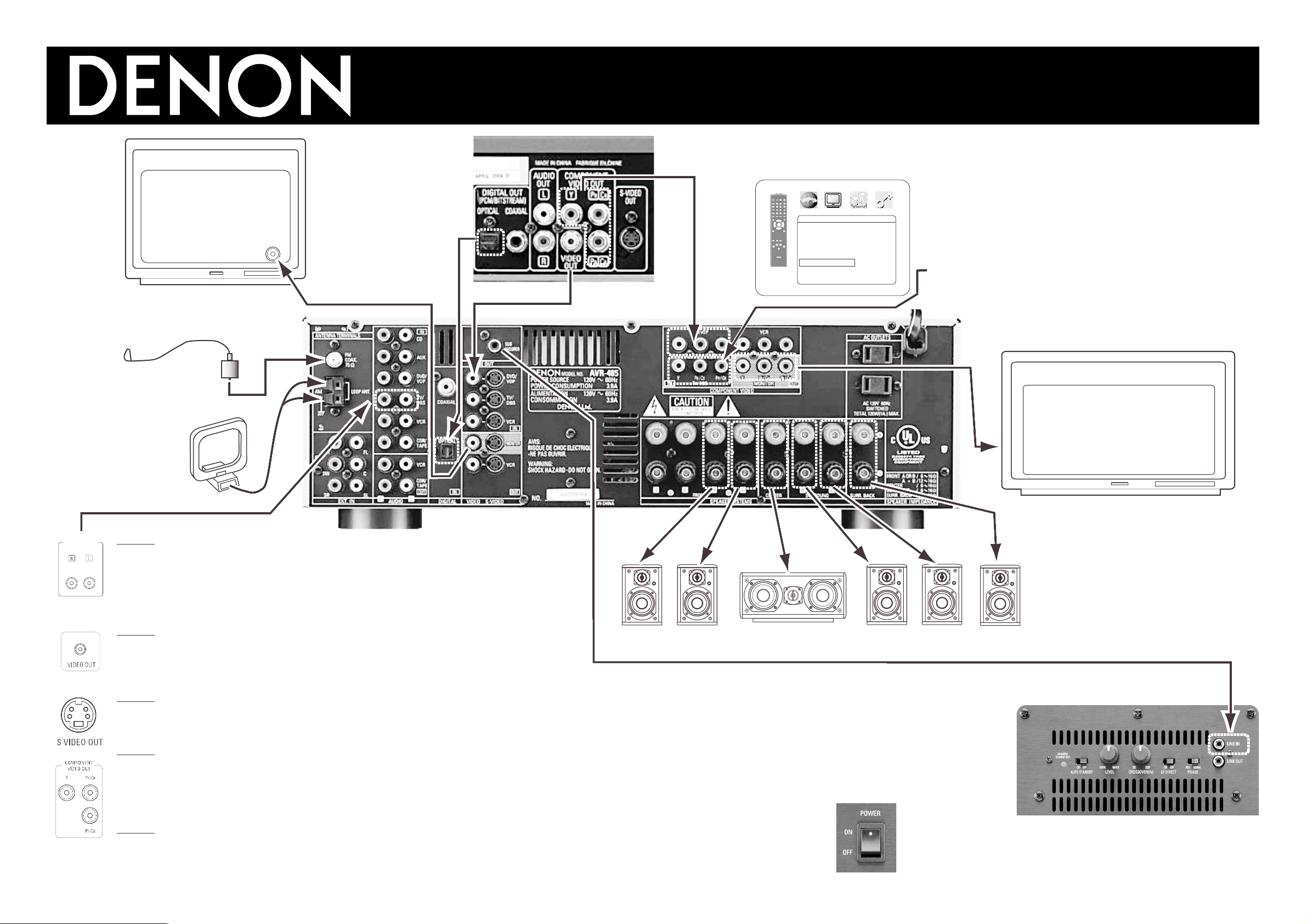
DHT-485DV Quick Connect Chart
OUT
Supplied FM
Antenna
Supplied AM
Antenna
00D 515 0972 009
Note:
Connect to the [LINE IN] jack of the subwoofer.
Switch settings as follows:
[AUTO STANDBY] = ON
Unit will “Wake up” when music plays. It will automatically go to “Standby”
after several minutes of no sound.
[LEVEL] Adjusts the volume of bass sound when LF DIRECT = OFF.
[CROSSOVER] Adjust to taste for the tonal character of the bass. Lower num-
ber for deeper bass, higher number for fuller bass, when LF DIRECT = OFF.
[LF DIRECT]= ON
Bass sound is controlled only by the
incoming signal.
[PHASE] = NORM
[POWER] = ON to use, OFF for vacation.
NOTE 1:
Connect TV “Audio Out” jacks to bring sound from the TV into the Denon. Some TVs may let you
choose between FIXED or VARIABLE audio outputs. FIXED means only the Denon will control
the volume, whereas VARIABLE means the TV volume control must be turned up in addition to
the Denon volume control. It is possible to connect all video devices to the TV directly for
both picture and sound. The TV will then send the sound to the Denon with just these two
Audio Wires. This is the simplest possible connection.
NOTE 2
:
The diagram shows COMPOSITE (yellow video cable) Video connections into the DENON from
the DVD, and out of the Denon into the TV. Connecting equipment this way allows the AVR-485
to route video when the Denon is powered on. If the Denon is turned off (standby), the picture
signal will no longer reach the TV.
NOTE 3
:
The S-VIDEO jack is an alternate optional video connection. If you use it, please note that video
signals DO NOT transfer between Composite and S-Video jacks in the receiver. Only what comes
in is what goes out.
NOTE 4
:
Some video products have COMPONENT VIDEO JACKS. These are still another alternate
optional video connection. This chart shows “COMPONENT” connection from the player to the
receiver then to the “DIGITAL TV MONITOR (DTV). You can save the cost of three wire by going
from PLAYER directly to the DTV unless you need the AVR-485 to switch between 2 or 3 COMPONENT video sources.
NOTE 5
:
To use the PROGRESSIVE SCAN feature of your Denon DVD-555S, you must have a digital TV
which will accept the progressive signal exclusively through Component Video Jacks. Progressive
scan is possible when the player is wired directly to the progressive input of a DIGITAL TV set, or
through the component connections of AVR-485 to DIGITAL TV set as shown in upper right.
DIGITAL TV Monitor
Standard TV Monitor
Standard VIDEO IN
(Yellow wire brings picture from devices connected to Denon.)
Optical Digital Out
from DVD player to
Optical Digital Jack
(for 5.1/6.1 sound).
RIGHT LEFT CENTER
HORIZONTAL BOX
RIGHT
SIDE
LEFT
SIDE
BACK
WALL
Your DENON DVD-555S features a special video output for
“Progressive Scan”. This type of picture signal is only possible with
DIGITAL TV sets that have a compatible 3 jack component input.
• Connect the DVD player’s color difference (component) video out-
put jacks (COMPONENT VIDEO OUTPUT) to the COMPONENT
VIDEO-1 IN jacks using 75Ω/ohms coaxial video pin-plug cords.
• In the same way, another video source with component video out-
puts such as a Satellite Tuner, Set Top Box, DVD Recorder etc., can
be connected to the VCR, TV/DBS color difference (component)
video jacks. (See NOTE 4 below left.)
Set progressive to “ON” or
“OFF” by using OSD of DVD555S.
AUDIO