


DCD-510
Table of contents
 Loading...
Denon Brand Company, D&M Holdings lnc.
e
Ver. 1
SERVICE MANUAL
CD PLAYER
MODEL JP E3 E2 EK E2A E1C E1K EUT
DCD-510AE
3
X0411 V.01 DE/CDM 0902
●
For purposes of improvement, specifications and design are subject to change without notice.
●
Please use this service manual with referring to the operating instructions without fail.
●
Some illustrations using in this service manual are slightly different from the actual set.

2
DCD-510AE
Please heed the points listed below during servicing and inspection.
◎ Heed the cautions!
Spots requiring particular attention when servicing, such
as the cabinet, parts, chassis, etc., have cautions indicated
on labels or seals. Be sure to heed these cautions and the
cautions indicated in the handling instructions.
◎ Caution concerning electric shock!
(1) An AC voltage is impressed on this set, so touching in-
ternal metal parts when the set is energized could
cause electric shock. Take care to avoid electric shock,
by for example using an isolating transformer and
gloves when servicing while the set is energized, un-
plugging the power cord when replacing parts, etc.
(2)There are high voltage parts inside. Handle with extra
care when the set is energized.
◎ Caution concerning disassembly and
assembly!
Though great care is taken when manufacturing parts from
sheet metal, there may in some rare cases be burrs on the
edges of parts which could cause injury if fingers are
moved across them. Use gloves to protect your hands.
◎ Only use designated parts!
The set's parts have specific safety properties (fire resis-
tance, voltage resistance, etc.). For replacement parts, be
sure to use parts which have the same properties. In par-
ticular, for the important safety parts that are marked z on
wiring diagrams and parts lists, be sure to use the desig-
nated parts.
◎ Be sure to mount parts and arrange
the wires as they were originally!
For safety reasons, some parts use tape, tubes or other in-
sulating materials, and some parts are mounted away from
the surface of printed circuit boards. Care is also taken with
the positions of the wires inside and clamps are used to
keep wires away from heating and high voltage parts, so
be sure to set everything back as it was originally.
◎ Inspect for safety after servicing!
Check that all screws, parts and wires removed or discon-
nected for servicing have been put back in their original po-
sitions, inspect that no parts around the area that has been
serviced have been negatively affected, conduct an insu-
lation check on the external metal connectors and between
the blades of the power plug, and otherwise check that
safety is ensured.
(Insulation check procedure)
Unplug the power cord from the power outlet, disconnect
the antenna, plugs, etc., and turn the power switch on. Us-
ing a 500V insulation resistance tester, check that the in-
sulation resistance between the terminals of the power
plug and the externally exposed metal parts (antenna ter-
minal, headphones terminal, microphone terminal, input
terminal, etc.) is 1MΩ or greater. If it is less, the set must
be inspected and repaired.
Concerning important safety
parts
Many of the electric and structural parts used in the set
have special safety properties. In most cases these prop-
erties are difficult to distinguish by sight, and using re-
placement parts with higher ratings (rated power and
withstand voltage) does not necessarily guarantee that
safety performance will be preserved. Parts with safety
properties are indicated as shown below on the wiring dia-
grams and parts lists is this service manual. Be sure to re-
place them with parts with the designated part number.
(1) Schematic diagrams ... Indicated by the z mark.
(2) Parts lists ... Indicated by the z mark.
Using parts other than the designated
parts could result in electric shock, fires or
other dangerous situations.
SAFETY PRECAUTIONS
The following check should be performed for the continued protection of the customer and service technician.
LEAKAGE CURRENT CHECK
Before returning the unit to the customer, make sure you make either (1) a leakage current check or (2) a line to chassis
resistance check. If the leakage current exceeds 0.5 milliamps, or if the resistance from chassis to either side of the
power cord is less than 460 kohms, the unit is defective.
LASER RADIATION
Do not stare into beam or view directly with optical instruments, class 3A laser product.
CAUTION
CAUTION
3
DCD-510AE
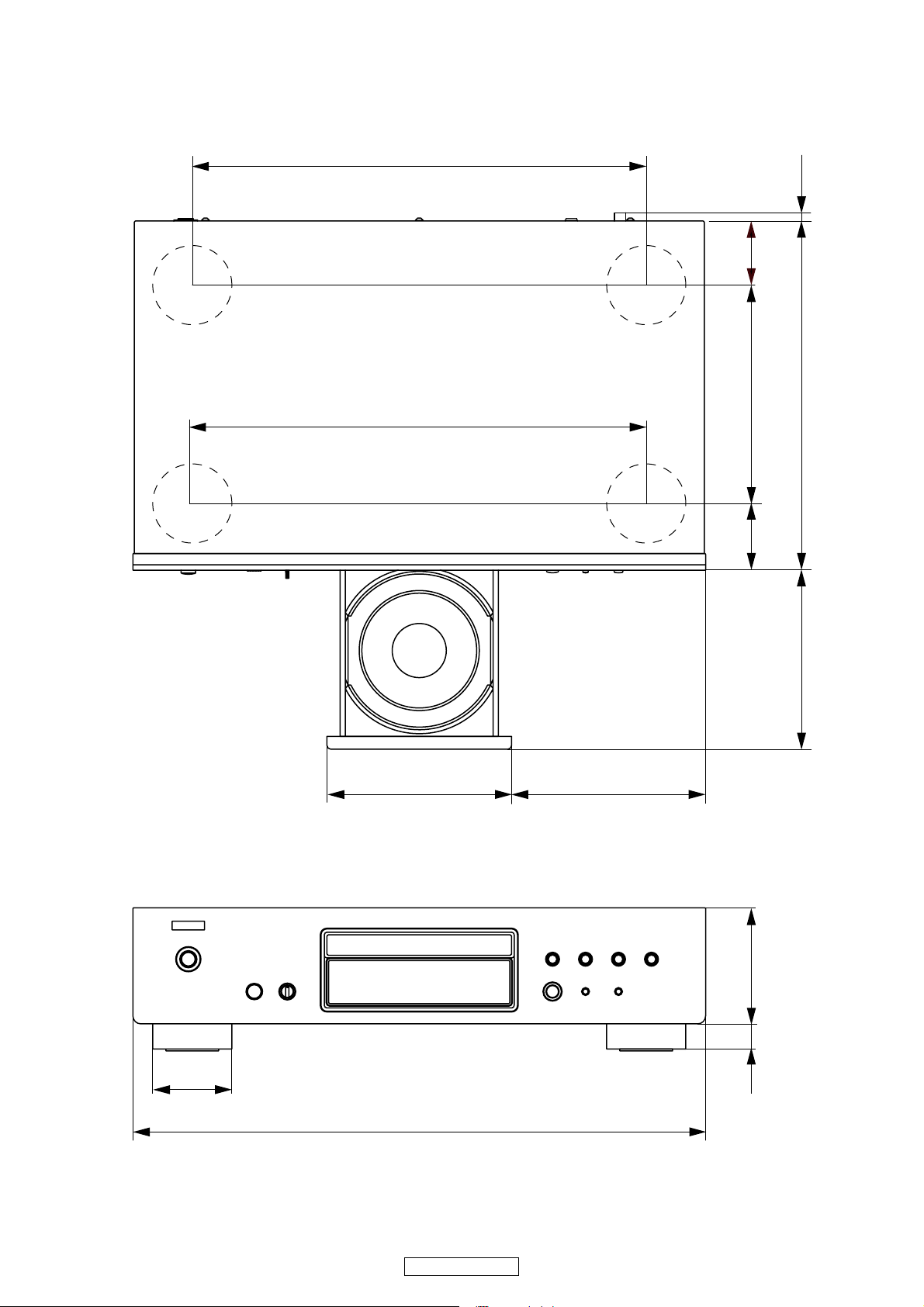
DIMENSION
OCZ
4
DCD-510AE
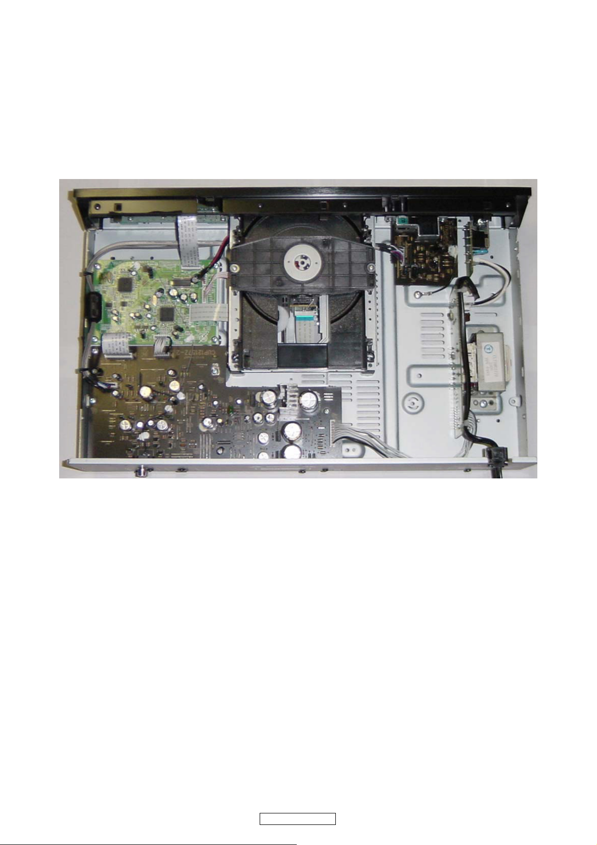
WIRE ARRANGEMENT
If wire bundles are untied or moved to perform adjustment or parts replacement etc.,be sure to rearrange them neatly as
they were originally bundled or placed afterward.
Otherwise, incorrect arrangement can be a cause of noise generation.
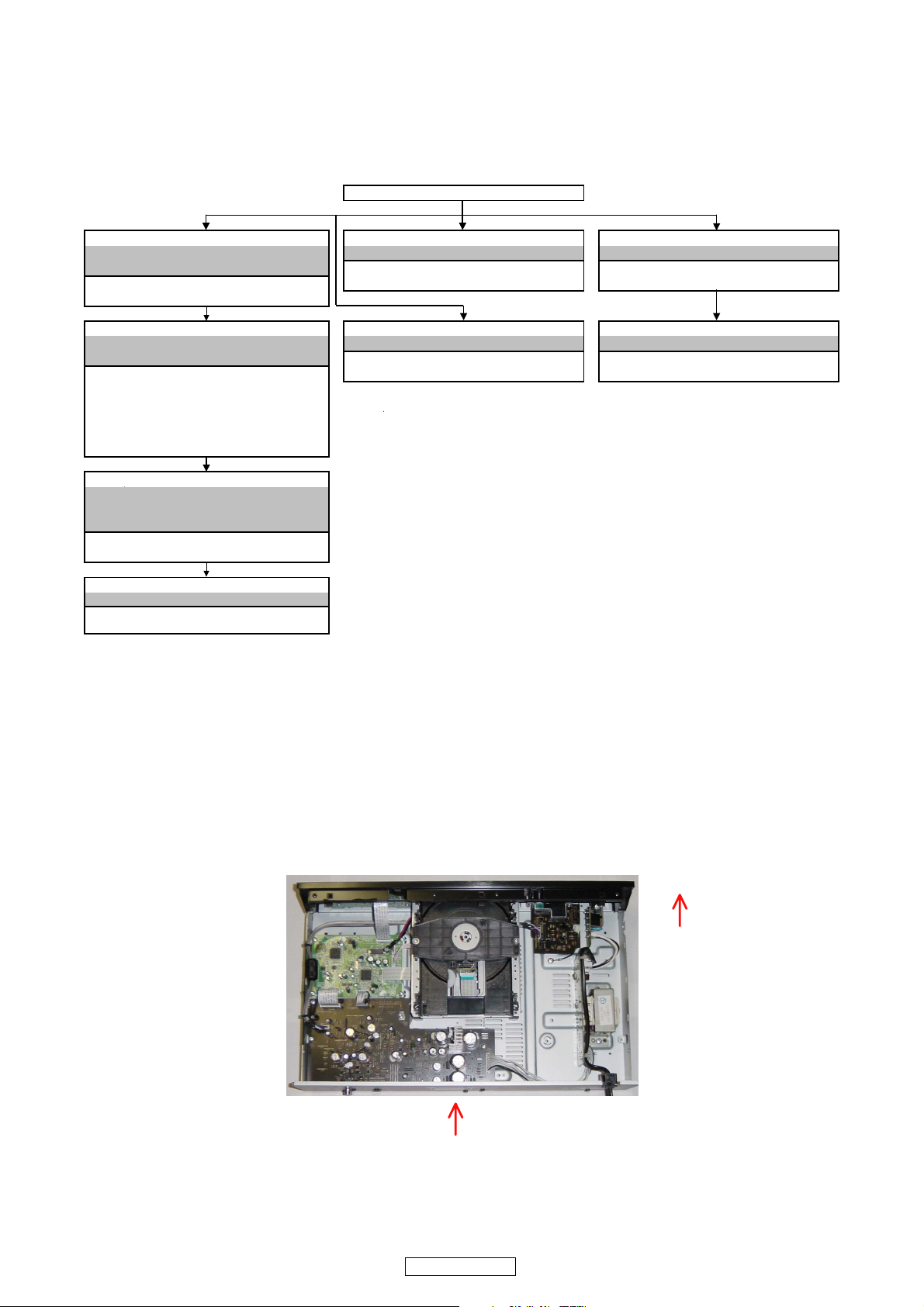
Wire arrangement viewed from the top
Front Panel side
Back Panel side
5
DCD-510AE
DISASSEMBLY
• Disassemble in order of the arrow of the figure of following flow.
• In the case of the re-assembling, assemble it in order of the reverse of the following flow.
• In the case of the re-assembling, observe "attention of assembling" it.
About the photos used for descriptions in the “DISASSEMBLY” section.
• The direction from which the photographs used herein were photographed is indicated at "Direction of photograph: ***" at
the left of the respective photographs.
• Refer to the table below for a description of the direction in which the photos were taken.
• Photographs for which no direction is indicated were taken from above the product.
TOP COVER
DOOR POWER UNIT REAR PANEL
Refer to "DISASSEMBLY 1.DOOR" Refer to "EXPLODED VIEW" Refer to "EXPLODED VIEW"
Refer to "EXPLODED VIEW" POWER UNIT REAR PANEL
DOOR (Ref. No. of EXPLODED VIEW : 8-3) (Ref. No. of EXPLODED VIEW : 9)
(Ref. No. of EXPLODED VIEW : 19)
FRONT PANEL ASSY POWER TRANS INPUT UNIT
Refer to "DISASSEMBLY 2.FRONT PANEL ASSY" Refer to "EXPLODED VIEW" Refer to "DISASSEMBLY 4.INPUT UNIT"
Refer to "EXPLODED VIEW" POWER TRANS INPUT UNIT
FRONT UNIT (Ref. No. of EXPLODED VIEW : 39) (Ref. No. of EXPLODED VIEW : 8-1)
(Ref. No. of EXPLODED VIEW : 8-2)
POWER SW UNIT
(Ref. No. of EXPLODED VIEW : 8-4)
HEADPHONE UNIT
(Ref. No. of EXPLODED VIEW : 8-5)
CD MECHANISM ASSY
Refer to "DISASSEMBLY
3.CD MECHANISM ASSY"
Refer to "EXPLODED VIEW"
CD MECHANISM ASSY
(Ref. No. of EXPLODED VIEW : 13)
MAIN PCB ASSY
Refer to "EXPLODED VIEW"
MAIN PCB ASSY
(Ref. No. of EXPLODED VIEW : 34)
The viewpoint of each photograph
(photography direction)
[View from above]
Front side
Direction of photograph: A
6
DCD-510AE
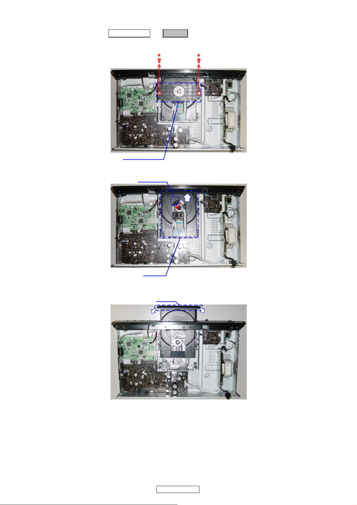
1. DOOR
(1) Take off the Chucking plate after removing screws.
(2) Open the CD tray by turning the Drive gear clockwise.
(3) Detach the DOOR.
Proceeding : TOP COVER → DOOR
Chucking plate
Drive gear
CD tray
DOOR
7
DCD-510AE
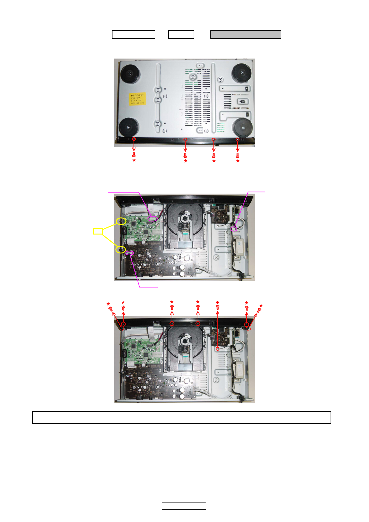
2. FRONT PANEL ASSY
(1) Remove the screws.
(2) Cut the clamp bands, disconnect the connector wires and FFC Cable.
(3) Remove the screws.
Please refer to "EXPLODED VIEW" for the disassembly method of each PCB included in FRONT PANEL ASSY.
Proceeding : TOP COVER → DOOR → FRONT PANEL ASSY
View from bottom
CN92
FFC Cable
cut
CN61
8
DCD-510AE
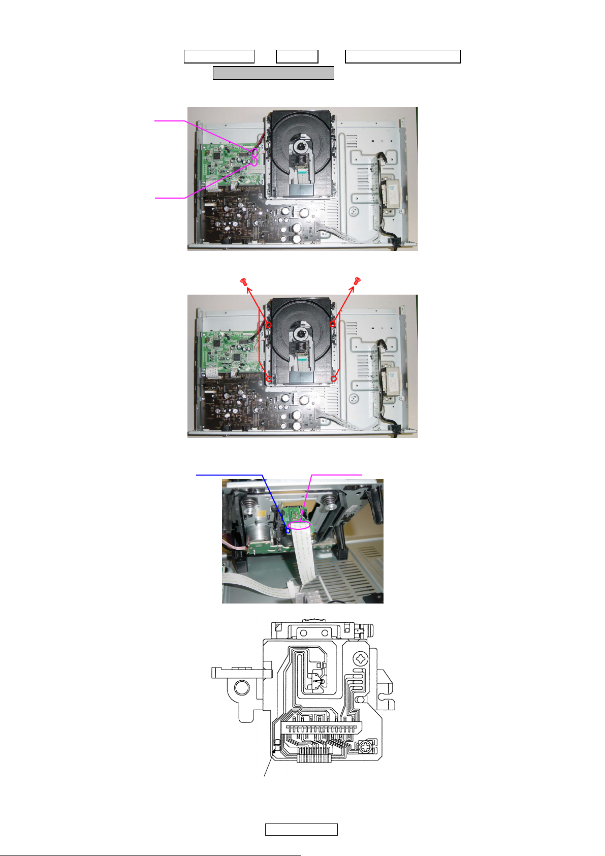
3. CD MECHANISM ASSY
(1) Disconnect the connector wires.
(2) Remove the screws.
(3) Laser short-circuit in Pick-up of CD MECHANISM, then disconnect the FFC Cable.
Proceeding : TOP COVER → DOOR → FRONT PANEL ASSY
→ CD MECHANISM ASSY
CN32
CN33
ً
ً
Soldering place
FFC Cable
Direction of photograph: A
Laser short-circuit
9
DCD-510AE
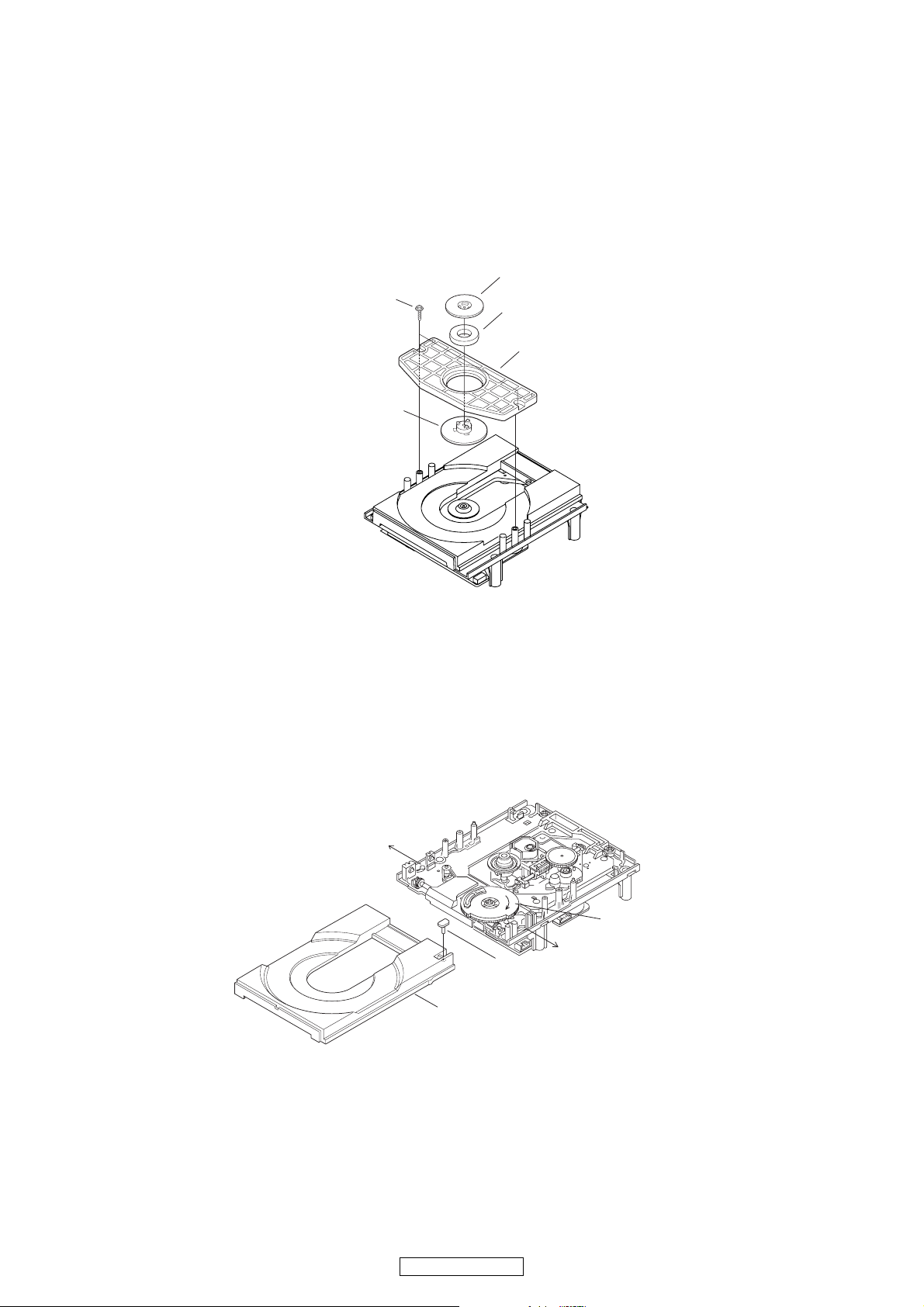
DISASSEMBLY OF MECHANIC
(Follow the procedure below in reverse order when reassembling.)
Caution : The optical pickup can damaged by sassily by static electricity charged on human body. Take necessary anti-static
measures when repairing around the optical pickup.
1. Chucking plate
(1) Remove 2 top screws, then detach the Chucking plate.
(2) Detaching the Chucking pulley and chucking yoke by removing the 3 hooks, when abandoning CD MECHA ass’y.
2. CD tray
When abandoning CD MECHA ass’y, please detach the CD tray.
(1) Detach the Sw pin on the CD tray.
(2) Open the CD tray by turning the Drive gear clockwise.
(3) Open the Stopper as shown in the fig., then detach CD tray.
Chucking yoke
Chucking plate
Chucking pulley
Screws
Mugnet
Stopper
Stopper
Sw pin
CD tray
Drive gear

10
DCD-510AE
Note Handling and Replacement of the Laser pick-up
1. Protection of the LD
Short a part of the LD circuit by soldering. After connection to a circuit, remove the short solder.
2. Precautions when handling the laser CD mechanism
• Handle the laser pick-up so that it is not exposed to dust.
• Do not leave the laser pick-up bare. Be sure to cover it.
• If dust adheres on lens of the pick-up, blow it off with a blower brush.
• Do not shock the laser pick-up.
• Do not watch the light of the laser pick-up.
3. Cautions on assembling and adjustment
• Be sure that to the bench, jig, head of soldering iron (with ceramic) and measuring instruments are well grounded.
• Workers who handle the laser pick-up must be grounded.
• The finished mechanism (prior to anchoring in the set) should be protected against static electricity and dust. The mecha-
nism must be stored that damaging outside forces are not received.
• When carrying the finished mechanism, hold it by the
chassis body
• For proper operation, storage and operating environment should not contain corrosive gases. For example H
2S, SO2, NO2,
CI
2 etc. In addition storage environment should not have materials that emit corrosive gases especially from silicic, cyanic,
formalin and phenol group. I the mechanism or the set, existence of corrosive gases may cause no rotation in motor.
4. Determining whether the laser pick-up is defective
•
Measure the waveform at RFO-VC on "MCU P.W.B. Unit ".
( For measuring points and waveforms, see pages 21.)
• The laser pick-up is OK if the amplitude level of the measured RFO waveform is between 0.4 and 1.1 Vp-p, defective oth-
erwise.
Protective soldering place for laser diode.
11
DCD-510AE
CD TEST MODE
No Key name Function Display
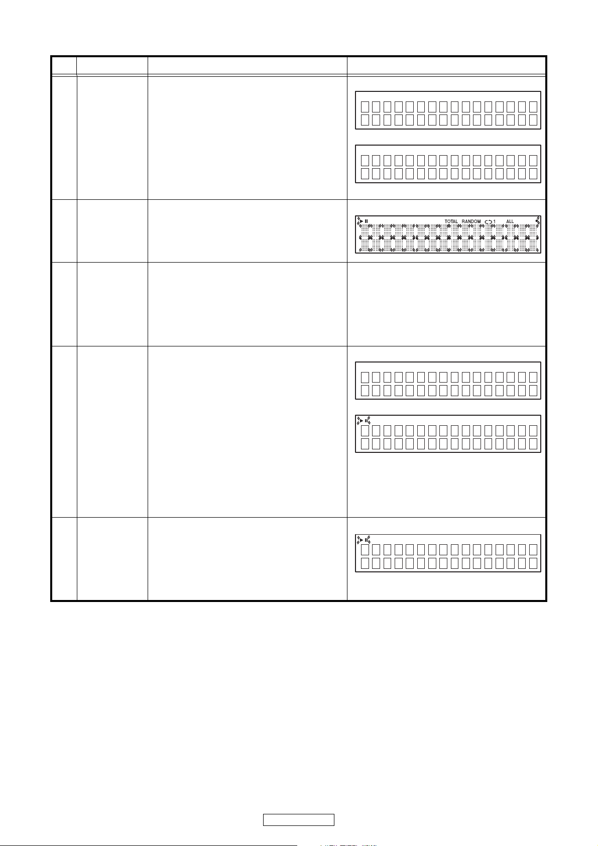
1
Version No. of
main μ-com
Display
q POWER switch is turned to on while pressing the
2 button on DCD-510AE.(Model name display)
w Press the 9 button continuously for over 3
seconds to display the version number of main
μ-com. Version number of main μ-com is
displayed for 5 seconds, the model name display
reappears.
・Turn off the POWER switch to clear this mode.
q
w
"***********" : Version number of main μ-com
2
FLD checking
mode
・Plug AC cord into power outlet while pressing
DIMMER button on DCD-510AE.
・All segment of FLD is turning on and off every
one second. MUTING ON.
・Turn off the POWER switch to clear this mode.
・All segment turn on and off.
3 Initialize
・Plug AC cord into power outlet while pressing
TIME/DISPLAY button on DCD-510AE.
・The system is reset, and once this is completed
the unit is set to the normal mode.
DIMMER : 100%
・The laser current initial value and laser
accumulated on time is not cleared.
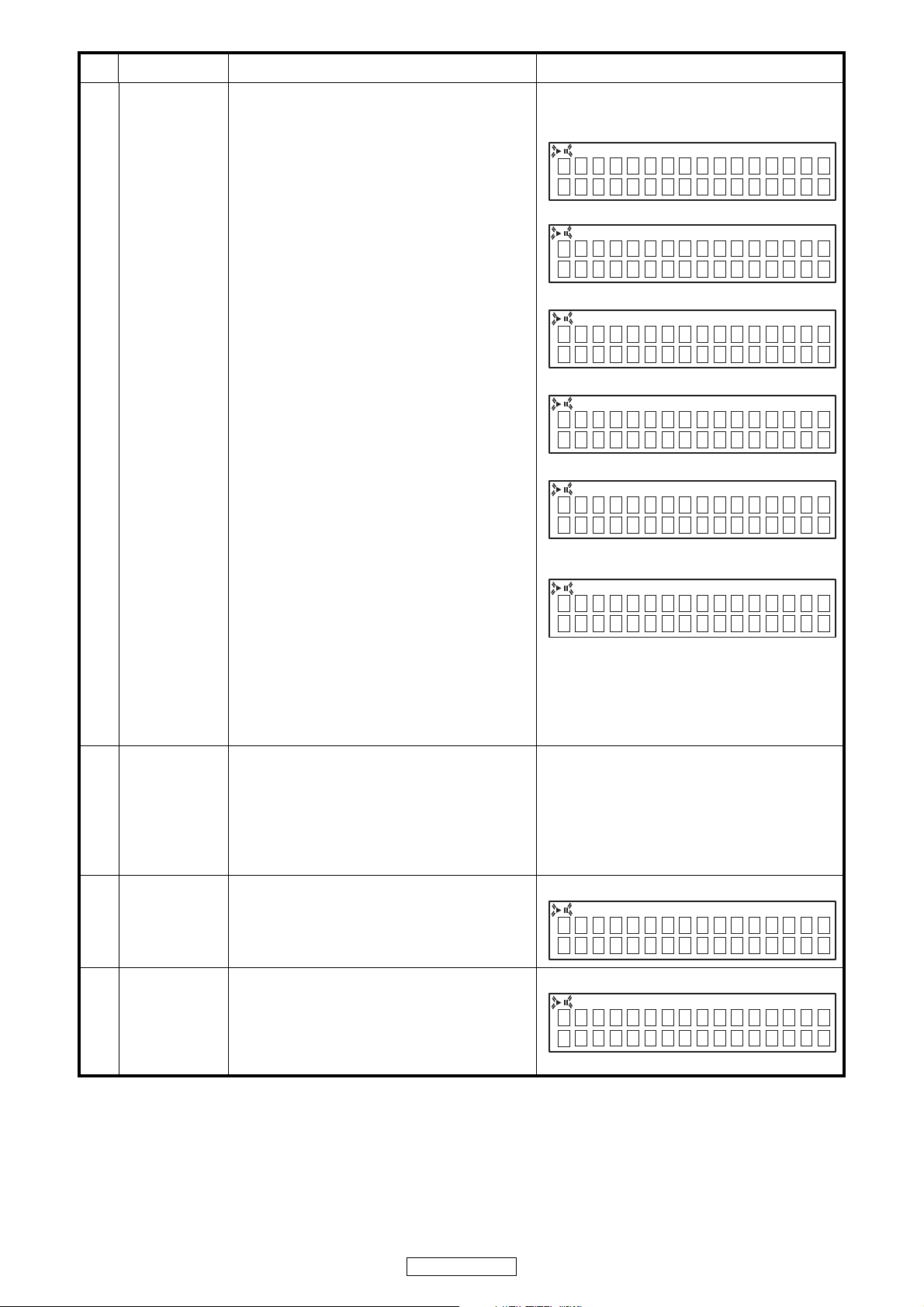
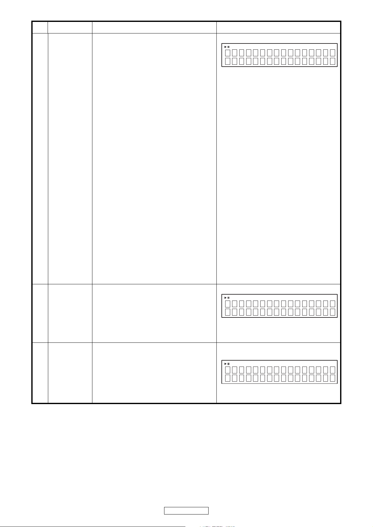
4 CD test mode
q POWER switch is turned to on while pressing the
2 button on DCD-510AE.(Model name display)
w Press the
/
13 button continuously for over 3
seconds. (CD test mode display)
・Move the slide to the initially set position (10 mm
towards the outside from the innermost position).
・Check by performing button input. Refer to 4.1 to
4.7.
・Cancel the mode by turning the power back on.
・Input of buttons other than those used in this
mode is not guaranteed. (OK if malfunction
occurs)
q
w
13 flashing
4.1 Disc loading
・Press the 5 button to open the tray.
・Set a disc on the tray, then press the 5 button
again to close the tray. The disc is mounted
automatically.
・Move the slide to the initially set position (10 mm
towards the outside from the innermost position)
and stop in this status.
・13 flashing
DCD-510AE
Ver * **********
DCD-510AE
00 CD TEST MODE
00 CD TEST MODE
12
DCD-510AE
4.2 Servo check
・Press the
/
13 button. Execute the following
steps.
q LD ON (with servo still stopped)
w FOCUS ON (disc rotation, tracking off)
If no disc loaded, retry then stop.
e CLV ON
r TRACKING ON
t SUB CODE readout (playback sound output)
y When display is as in t and the
/
13 button is
pressed, conduct BER (Block Error Rate)
display for 2 seconds.
・Press the 2 button, CD test mode display
reappears.
bPress
/
13 button continuously for over 1
second to switch directly to SUB CODE readout
in step
t.
・
13 flashing
q
w
e
r
t
@@ : T.No, XX:XX : Time
y
###### : B.E.R.
4.3
Pickup
movement
・In the stop mode, pickup moves in REV (inwards)
or FWD (outwards) direction when 8 or 9
button pressed.
・When 8 button pressed, move to stop
operation after detection that inner switch has
turned on.
・Pickup movement stops when button released.
Continuous display of previous time
4.4 Stop
・When 2 button is pressed, play operation and
servo stop.
・After stopping, conduct reading of auto adjust
values.
・13 flashing
4.5 All servo on
・When TIME/DISPLAY button is pressed, all
servos turn on, auto adjustment is performed and
switch to playback operation. (Playback sound
output)
・13 flashing
@@ : T.No, XX:XX : Time
No
Key name
Function Display
01 LD ON
02 Focus ON
03 CLV ON
04 Tr acking ON
05 @@
Tr
XX:XX
ERR ### ###
00 CD TEST MODE
@@
Tr
XX:XX
13
DCD-510AE
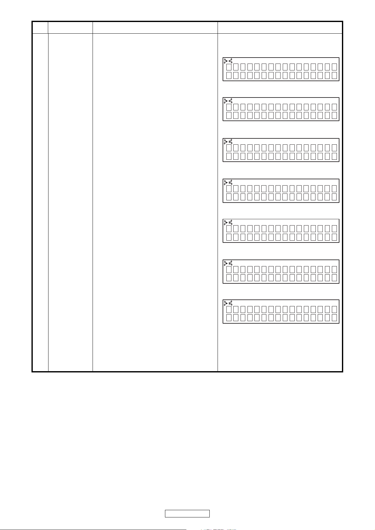
4.6
Adjustment value
display
・When DIMMER button is pressed, the
adjustment values are displayed in the following
order.
q FOCUS BALANCE
w FOCUS GAIN
e TRACKING BALANCE
r TRACKING GAIN
tFOCUS OFFSET
y TRACKING OFFSET
u RFRP
i Return to q.
・
Press the 2 button, CD test mode display (4 w)
reappears.
(Note)If auto adjustment is not completed, proper
values are not displayed.
・13 flashing
q
XX : Adjustment value
w
XX : Adjustment value
e
XX : Adjustment value
r
XX : Adjustment value
t
XX : Adjustment value
y
XX : Adjustment value
u
XX : Adjustment value
No
Key name
Function Display
X
X
F
OCUS BALANCE
X
X
F
OCUS GAIN
X
X
T
RACKING BALANCE
X
X
T
RACKING GAIN
X
X
F
OCUS OFFSET
X
X
T
RACKING OFFSET
X
X
R
FRP
14
DCD-510AE
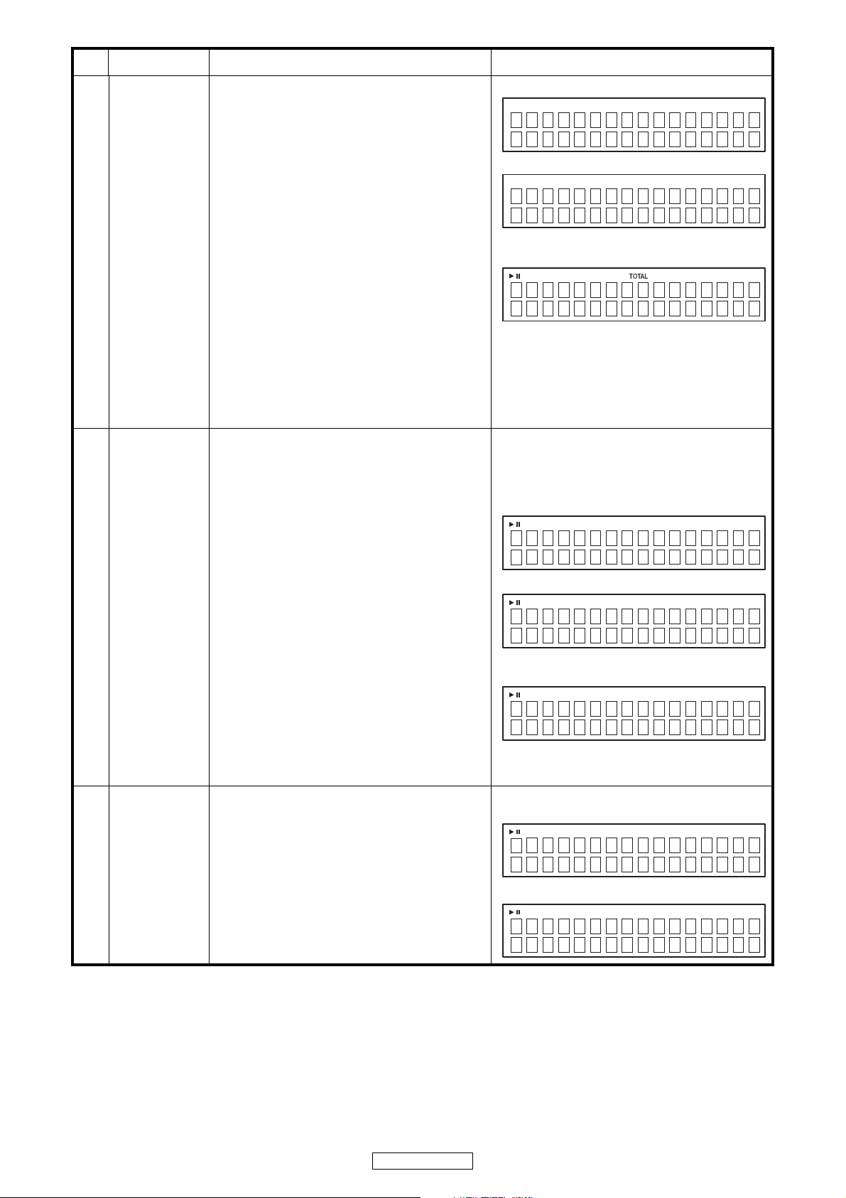
5
CD heat run
mode
q Set the disc in the tray. POWER switch is turned
to on while pressing the 2 button on DCD-
510AE.(Model name display)
w Press the 9 button continuously for over 3
seconds to display the version number. Version
number is displayed for 5 seconds, the error
display reappears.
e Press the
/
13 button continuously for over 3
seconds while the version number is displayed.
・Switches to mode according to button input.
See 5.1 and 5.2.
・If an error occurs, display the error and stop
operation at that point. Number of operations
held. See 5.3 to 5.5.
・Heat run no. cleared when 2 button pressed.
・Mode canceled and tray opened after 5 button
pressed.
・Turn off the POWER switch to clear this mode.
q
w
"***********" : Version number of main μ-com
e Normal display except when 13 lights.
5.1
Normal heat run
mode
・The CD heat run mode is launched. Once writing
of the TOC data is completed, press the
/
13
button. Count this as the 0th heat run repetition.
q Play from the first to last track on disc.
w If disc being used has less than 20 tracks, play
all tracks. If disc has 21 or more tracks, skip to
final track after playback of first track has
finished.
e After disc playback has finished, move pickup
to innermost position and open tray.
r When loader open status detected, close tray
again, re-read TOC and start playback from the
first track on the disc.
t The heat run repetition no. is incremented
(increased by 1) when the tray is opened.
y Conduct q to t repeatedly.
・ 13 lights
q,w In cases other than when 13 is lights, same
display as during normal playback.
e
XXXX : No. of heat run repetitions
r
5.2
Automatic
mounting mode
・After CD heat run mode has started and reading
the TOC has finished, press the 2 button button
once in the stop mode.
・TOC reading ⇒ Search for first track on disc ⇒
tray open ⇒ tray close ⇒ TOC reading ⇒ repeat.
No. heat run repetitions displayed on time display
section.
・Increment the heat run repetition no. at the point
when the loader has finished opening.
・ 13 lights
While tray opened
When tray closed
No
Key name
Function Display
DCD-510AE
Ver * **********
CD 11
Tr
42:52
CD 01
Tr
01:47
CD XXXX
CD 01
Tr
:
CD XXXX
CD 01
Tr
:
15
DCD-510AE
5.3 Error display
E1-00 : Disc cannot be detected
E1-01 : Tracking offset adjustment not possible
E1-02 : Focus offset adjustment not possible
E2-00 : Focus servo dropped during playback.
E2-01 : Focus servo dropped during searching.
E2-03 : Focus servo dropped during TOC reading.
E2-06 : Focus servo dropped during manual
search.
E2-10 : Subcode can no longer be read during
playback
E2-11 : Subcode can no longer be read during
searching
E2-12 : Subcode can no longer be read during
TOC reading
E2-14 : Subcode cannot be read during pause
E2-15 : Subcode cannot be read during manual
search
E3-00 : TOC could not be read within specified
time
E3-01 : PVD/SVD analysis could not be
completed within specified time
E4-04 : Search time out
E4-05 : Error in communications with CD decoder
E5-00 : Inner switch not on
E6-00 : Inner switch not off
E9-00 : Error in CD microprocessor
E9-01 : Other error
・ 13 lights
X-XX : Error display
5.4
Error display
switching (1)
・Press the 9 button while the error is displayed.
・ No. heat runs is displayed for 5 seconds, the error
display reappears.
・ 13 lights
XXXX : No. of heat run repetitions
・Error display reappears after 5 seconds. See 5.3.
5.5
Error display
switching (2)
・Press the 8 button while the error is displayed.
・ The track no. and time when the error occurred is
displayed for 5 seconds, then error display
reappears.
・In cases other than when 13 is lights, same
display as during normal playback.
・Error display reappears after 5 seconds. See 5.3.
No
Key name
Function Display
CD EX-XX
CD XXXX
CD 01
Tr
:01 47
16
DCD-510AE
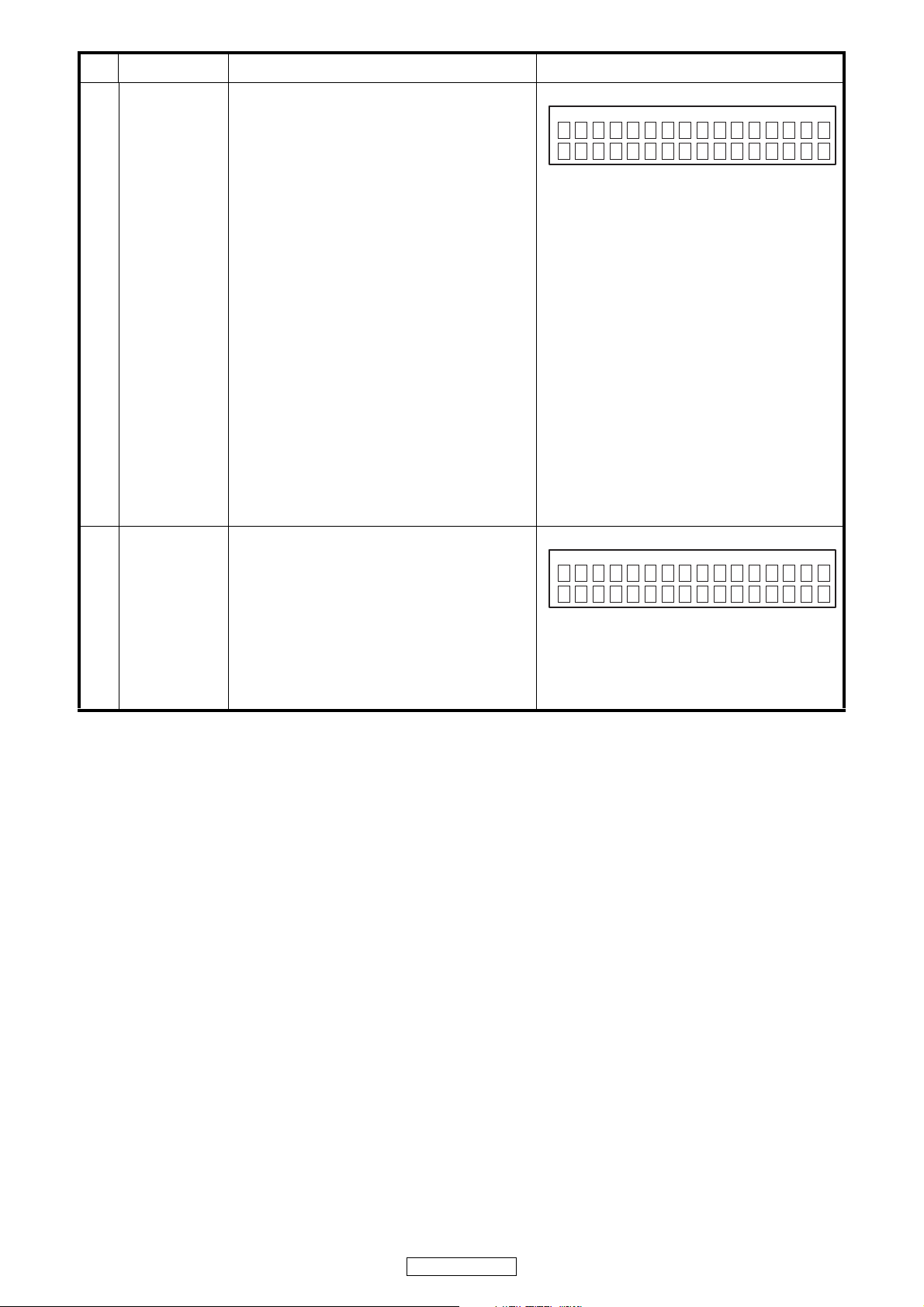
6
Accumulated
laser on time
display
q POWER switch is turned to on while pressing the
2 button on DCD-510AE.(Model name display)
w Press the 8 button continuously for over 3
seconds to display the accumulated laser on
time. Accumulated laser on time is displayed for
5 seconds, the error display reappears.
・The laser drive times are added and the result
is displayed.
・One count corresponds to 10 minutes. (Values
under 10 minutes are discarded.)
・Count values are stored in the EEPROM every
10 minutes.
・The accunulated laser on time is displayed in
hours.
・The count values are not cleared, even when
the set is reset.
・Minimun display specification (possible even
with display times above those below)
No. digits store in EPROM: 4, 0xFFFF
No. digits displayed: 5
・When the time exceeds 10922 hours, the stored
data is not updated and the value is fixed to
0xFFFF.
(The display is fixed to 10922 hours.)
6.1
Initialization of a
count value
・When the
/
13 button is pressed for over 5 sec-
onds while the accumulated laser on time is
displayed, the count value is reset.
・After resetting is completed, the display in
6(00000hours on the top line) reappears, and
after 5 seconds the model name display reap-
pears.
・Initialization of a count value is performed upon
shipment from the factory and when the mech-
anism is replaced.
No
Key name
Function Display
X
XXXX hour
L
ASER ON TIME
C
LEAR
L
ASER ON TIME
Loading...