

Page 1
Ver. 2
Please refer to the
MODIFICATION NOTICE.
SERVICE MANUAL
MODEL JP E3 E2 EK E2A E1C EUT
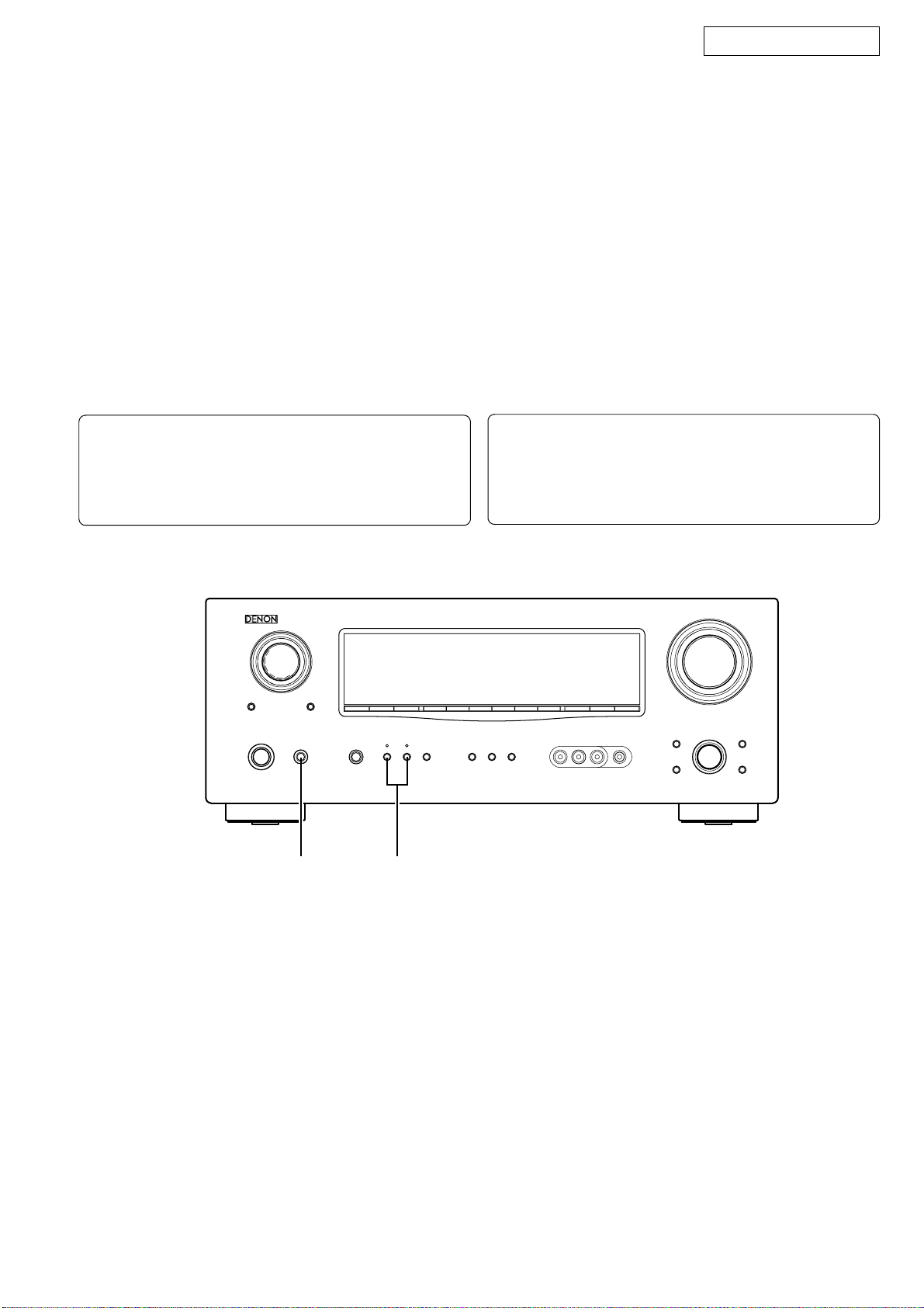
AVR-1908
AVR-788
33 333
3
AV SURROUND RECEIVER
注 意
サービスをおこなう前に、このサービスマニュアルを
必ずお読みください。本機は、火災、感電、けがなど
に対する安全性を確保するために、さまざまな配慮を
おこなっており、また法的には「電気用品安全法」に
もとづき、所定の許可を得て製造されております。
従ってサービスをおこなう際は、これらの安全性が維
持されるよう、このサービスマニュアルに記載されて
いる注意事項を必ずお守りください。
●
For purposes of improvement, specifications and
design are subject to change without notice.
●
Please use this service manual with referring to the
operating instructions without fail.
●
Some illustrations using in this service manual are
slightly different from the actual set.
Denon Brand Company, D&M Holdings lnc.
●
本機の仕様は性能改良のため、予告なく変更すること
があります。
●
補修用性能部品の保有期間は、製造打切後 8 年です。
●
修理の際は、必ず取扱説明書を参照の上、作業を行っ
てください。
●
本文中に使用しているイラストは、説明の都合上現物
と多少異なる場合があります。
X0353 V.02 DE/CDM 0712
Page 2
SAFETY PRECAUTIONS
The following check should be performed for the continued protection of the customer and service technician.
LEAKAGE CURRENT CHECK
Before returning the unit to the customer, make sure you make either (1) a leakage current check or (2) a line to chassis
resistance check. If the leakage current exceeds 0.5 milliamps, or if the resistance from chassis to either side of the power
cord is less than 460 kohms, the unit is defective.
AVR-1908 / AVR-788
CAUTION
Please heed the points listed below during servicing and inspection.
◎ Heed the cautions!
Spots requiring particular attention when servicing, such as
the cabinet, parts, chassis, etc., have cautions indicated on
labels or seals. Be sure to heed these cautions and the cautions indicated in the handling instructions.
◎ Caution concerning electric shock!
(1) An AC voltage is impressed on this set, so touching inter-
nal metal parts when the set is energized could cause
electric shock. Take care to avoid electric shock, by for example using an isolating transformer and gloves when
servicing while the set is energized, unplugging the power
cord when replacing parts, etc.
(2)There are high voltage parts inside. Handle with extra care
when the set is energized.
◎
Caution concerning disassembly and assembly!
Though great care is taken when manufacturing parts from
sheet metal, there may in some rare cases be burrs on the
edges of parts which could cause injury if fingers are moved
across them. Use gloves to protect your hands.
◎ Only use designated parts!
The set's parts have specific safety properties (fire resistance, voltage resistance, etc.). For replacement parts, be
sure to use parts which have the same properties. In particular, for the important safety parts that are marked ! on wiring
diagrams and parts lists, be sure to use the designated parts.
◎ Be sure to mount parts and arrange the
wires as they were originally!
For safety reasons, some parts use tape, tubes or other insulating materials, and some parts are mounted away from the
surface of printed circuit boards. Care is also taken with the
positions of the wires inside and clamps are used to keep
wires away from heating and high voltage parts, so be sure to
set everything back as it was originally.
◎ Inspect for safety after servicing!
Check that all screws, parts and wires removed or disconnected for servicing have been put back in their original positions, inspect that no parts around the area that has been
serviced have been negatively affected, conduct an insulation
check on the external metal connectors and between the
blades of the power plug, and otherwise check that safety is
ensured.
(Insulation check procedure)
Unplug the power cord from the power outlet, disconnect the
antenna, plugs, etc., and turn the power switch on. Using a
500V insulation resistance tester, check that the insulation resistance between the terminals of the power plug and the externally exposed metal parts (antenna terminal, headphones
terminal, microphone terminal, input terminal, etc.) is 1MΩ or
greater. If it is less, the set must be inspected and repaired.
CAUTION
Many of the electric and structural parts used in the set have
special safety properties. In most cases these properties are
difficult to distinguish by sight, and using replacement parts
with higher ratings (rated power and withstand voltage) does
not necessarily guarantee that safety performance will be preserved. Parts with safety properties are indicated as shown
below on the wiring diagrams and parts lists is this service
manual. Be sure to replace them with parts with the designated part number.
(1) Schematic diagrams ... Indicated by the ! mark.
(2) Parts lists ... Indicated by the ! mark.
Concerning important safety parts
Using parts other than the designated parts
could result in electric shock, fires or other
dangerous situations.
注 意
サービス、点検時にはつぎのことにご注意願います。
◎注意事項をお守りください!
サービスのとき特に注意を必要とする個所についてはキャ
ビネット、部品、シャーシなどにラベルや捺印で注意事項を
表示しています。これらの注意書きおよび取扱説明書などの
注意事項を必ずお守りください。
◎感電に注意!
(1) このセットは、交流電圧が印加されていますので通電時
に内部金属部に触れると感電することがあります。従っ
て通電サービス時には、絶縁トランスの使用や手袋の着
用、部品交換には、電源プラグを抜くなどして感電にご
注意ください。
(2) 内部には高電圧の部分がありますので、通電時の取扱に
は十分ご注意ください。
◎分解、組み立て作業時のご注意!
板金部品の端面の『バリ』は、部品製造時に充分管理をして
おりますが、板金端面は鋭利となっている箇所が有りますの
で、部品端面に触れたまま指を動かすとまれに怪我をする場
合がありますので十分注意して作業して下さい。手の保護の
ために手袋を着用してください。
◎指定部品の使用!
セットの部品は難燃性や耐電圧など安全上の特性を持った
ものとなっています。従って交換部品は、使用されていたも
のと同じ特性の部品を使用してください。特に配線図、部品
表に!印で指定されている安全上重要な部品は必ず指定の
ものをご使用ください。
◎部品の取付けや配線の引きまわしは、
元どおりに!
安全上、テープやチューブなどの絶縁材料を使用したり、プ
リント基板から浮かして取付けた部品があります。また内部
配線は引きまわしやクランパーによって発熱部品や高圧部
品に接近しないように配慮されていますので、これらは必ず
元どおりにしてください。
◎サービス後は安全点検を!
サービスのために取り外したねじ、部品、配線などが元どお
りになっているか、またサービスした個所の周辺を劣化させ
てしまったところがないかなどを点検し、外部金属端子部
と、電源プラグの刃の間の絶縁チェックをおこなうなど、安
全性が確保されていることを確認してください。
(絶縁チェックの方法)
電源コンセントから電源プラグを抜き、アンテナやプラグな
どを外し、電源スイッチを入れます。500V 絶縁抵抗計を用
いて、電源プラグのそれぞれの端子と外部露出金属部[アン
テナ端子、ヘッドホン端子、マイク端子、入力端子など]と
の間で、絶縁抵抗値が1 MΩ 以上であることを確認してく
ださい。この値以下のときはセットの点検修理が必要です。
注 意
本機に使用している多くの電気部品、および機構部品は安全
上、特別な特性を持っています。この特性はほとんどの場合、
外観では判別つきにくく、またもとの部品より高い定格(定
格電力、耐圧)を持ったものを使用しても安全性が維持され
るとは、限りません。安全上の特性を持った部品は、この
サービスマニュアルの配線図、部品表につぎのように表示し
ていますので必ず指定されている部品番号のものを使用願
います。
(1) 配線図…
(2) 部品表…
安全上重要な部品について
!マークで表示しています。
!マークで表示しています。
指定された部品と異なるものを使用した場合に
は、感電、火災などの危険を生じる恐れがあり
ます。
2
Page 3
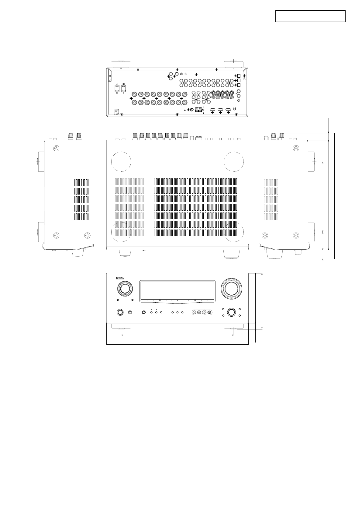
DIMENSION
AVR-1908 model
AVR-1908 / AVR-788
21.2
344.0
434.0
171.0
16.0 155.0
335.2
26.5 54.7 214.5
382.9
3
Page 4
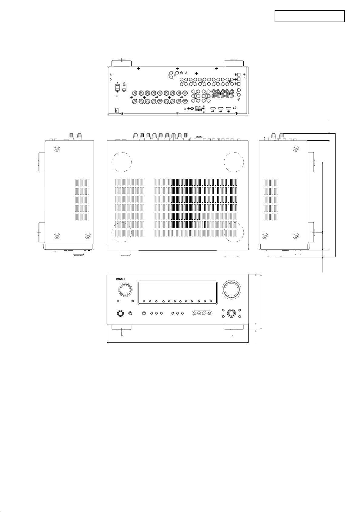
AVR-788 model
AVR-1908 / AVR-788
21.2
344.0
434.0
155.0
171.0
16.0
214.5
20.7 54.7
335.2
377.1
4
Page 5
AVR-1908 / AVR-788
CAUTION IN SERVICING
Initializing AV SURROUND RECEIVER/AMPLIFIER
AV SURROUND RECEIVER/AMPLIFIER initialization should be
performed when the µcom, peripheral parts of µcom, and Digital
P.W.B. are replaced.
1. Switch off the unit.
2. Hold the following SPEAKERS-A button and SPEAKERS-B
button, and switch on the unit.
3. Check that the entire display is flashing with an interval of
about 1 second, and release your fingers from the 2 buttons
and the microprocessor will be initialized.
Note:・If step 3 does not work, start over from step 1.
・ All user settings will be lost and this factory setting will
be recovered when this initialization mode.
So make sure to memorize your setting for restoring
after the initialization.
サービス時の注意事項
AVサラウンドレシーバー / アンプの初期化に
ついて
マイコンやマイコン周辺部品、Digital 基板等を交換した場合
は、AV サラウンドレシーバー / アンプの初期化を行って下さ
い。
1. on/off ボタンを OFF にします。
2. SPEAKERS-A ボタンと SPEAKERS-B ボタンを同時に押しな
がら、on/off ボタンを押して ON にします。
3. ディスプレイ表示が約 1秒間隔で点滅するのを確認後、2
つのボタンから指を離します。
*マイコンが初期化されます。
注意 :・上記 3 の状態にならない場合は、もう一度操作 1 か
らやり直してください。
・初期化を行うとお客様が設定した内容が工場出荷状
態に戻りますので、あらかじめ設定内容を控えてお
き初期化後再設定してください。
1,2
2,3
JIG to use for servicing
When you repair the printing board, you can use the following
JIG (Extention cable kit). Please order to Denon Official Service
Distributor in your region if necessary.
00D SPK- 561 EXTENSION UNIT KIT : 1 Set
00D SPK- 562 9120 CONN. JOINT KIT : 1 Set
The illustration is AVR-1908.
サービス時に使用する治具について
基板を修理する際、使用する治具 ( 延長ケーブルキット)は
下記のとおりです。
必要に応じて販社サービスへ注文下さい。
00DSPK-561EXTENSIONUNITKIT:1 式
00DSPK-5629120CONN.JOINTKIT:1 式
5
Page 6
AVR-1908 / AVR-788
on/off button
STATUS
DIMMER
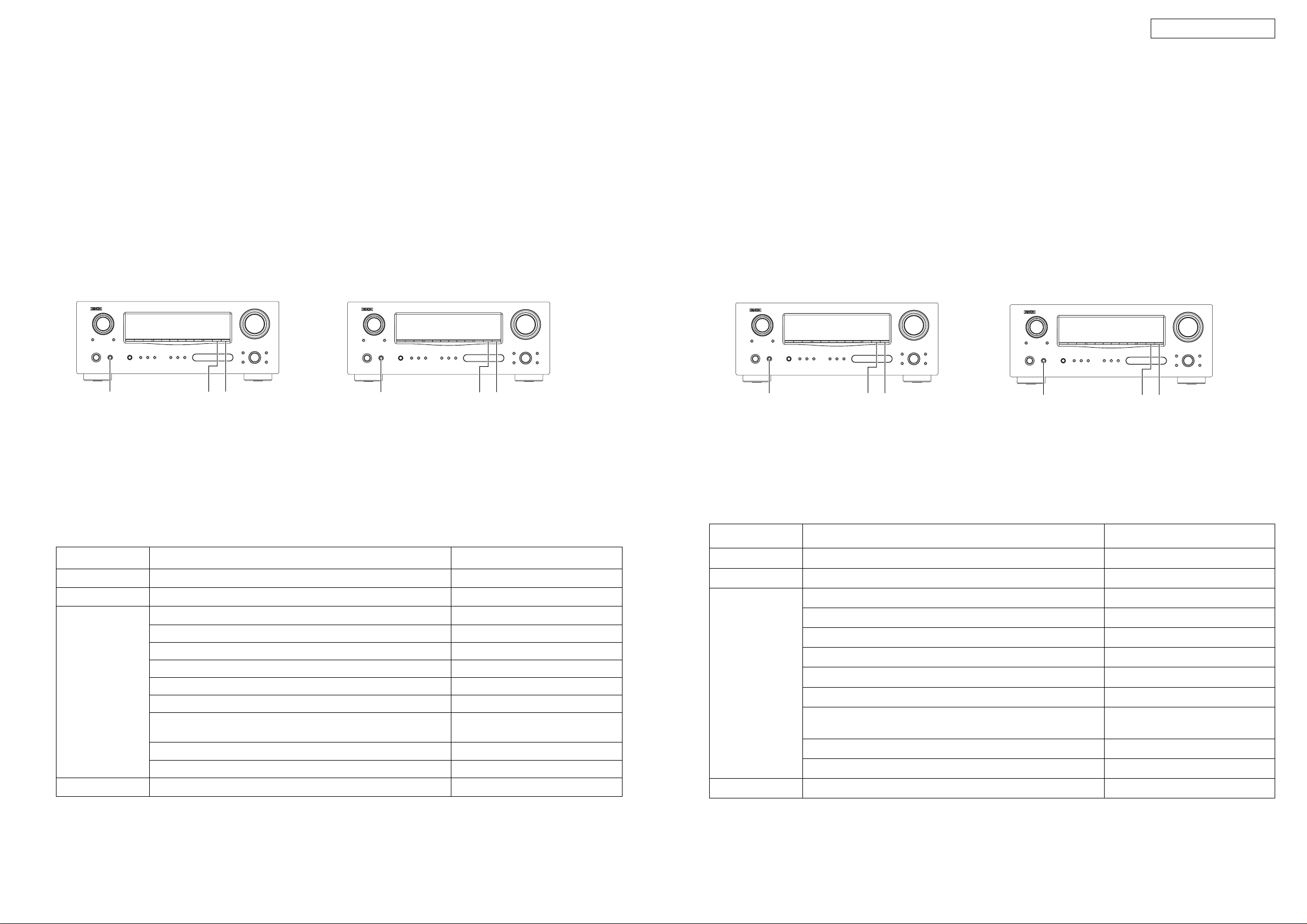
E3,EUT,E1C model
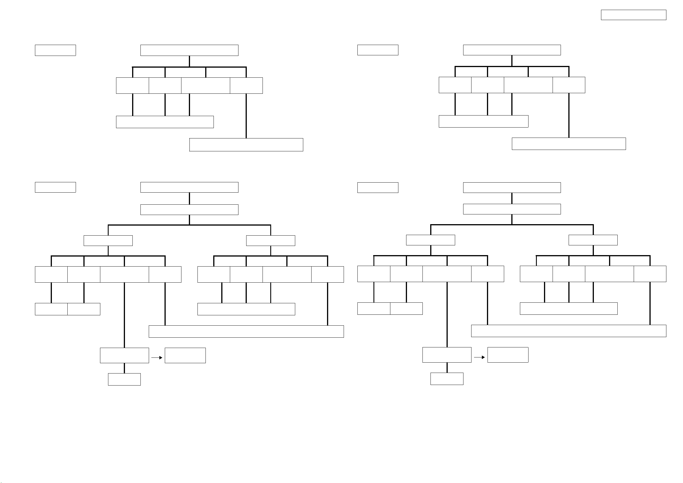
CHECK WITH TEST MODE
µcom/DSP Error Display Mode
1. Operation Spec
µcom version display mode:
When the following conditions are satisfied at its starting state, error information is displayed before version information.
Starting method (same as µcom version display):
E3,EUT,E1C model
While pressing 2 buttons, "STATUS" and "DIMMER", turn on on/off button.
Then, press "STATUS" button to display the following information on the FL Display.
E2,E2A model
While pressing 2 buttons, "RT" and "PTY", turn on on/off button.
Then, press "RT" button to display the following information on the FL Display.
E3,EUT,E1C model
E2,E2A model
テストモードによるチェック方法
マイコン・DSP エラー表示モード
1. 動作仕様
マイコンバージョン表示モード :
起動状態にて下記の条件に該当した場合は、バージョン情報表示の前にエラー情報を表示します。
起動方法 ( マイコンバージョン表示と同様 ):
● E3,EUT,E1C モデル
"STATUS","DIMMER" の 2 つのボタンを押した状態で、on/off ボタンを押して電源を入れます。
その後、"STATUS" ボタンを押すと下表の内容が FLDisplay に表示されます。
● E2,E2A モデル
"RT","PTY" の 2 つのボタンを押した状態で、on/off ボタンを押して電源を入れます。
その後、"RT" ボタンを押すと下表の内容が FLDisplay に表示されます。
E2,E2A model
2. Display Order
3. Display
①
② DIR NG
③ DSP1 NG
④
on/off button
DIMMER
STATUS
on/off button
PTY
RT
Error information →Destination information →Main-µcom version information → Sub-µcom version information
→ DSP version information
Any one of the following list is displayed, in the priority of ①②③④ .
Condition State Display
Sub-µcom NG
Both SUB/DSP OK
No response from Sub-µcom
No response from DIR
When DSP boot, executing DSP reset makes no change to BUSY port "L".
No change to BUSY port "L" before issuing DSP command.
When DSP data read, executing WRITE="L" makes no change to ACK="H".
When DSP data read, executing REQ="L" makes no change to ACK="L".
When DSP data write, executing WRITE="H" makes no change to ACK="H".
When DSP data write, executing REQ="L" makes no change to ACK="L".
When DSP special code boot, executing DSP reset makes no change to
BUSY port "L".
No change to BUSY port "L" before issuing DSP special read command.
No change to BUSY port "L" before DSP version read.
" □ SUB □□ ERROR □01□ "
" □ DIR □□ ERROR □01□ "
" □ DSP1 □ ERROR □01□ "
" □ DSP1 □ ERROR □02□ "
" □ DSP1 □ ERROR □03□ "
" □ DSP1 □ ERROR □04□ "
" □ DSP1 □ ERROR □05□ "
" □ DSP1 □ ERROR □06□ "
" □ DSP1 □ ERROR □11□ "
" □ DSP1 □ ERROR □12□ "
" □ DSP1 □ ERROR □13□ "
(No error display, version display only)
RT
on/off button
PTY
2. 表示順序
エラー情報→仕向地表示→メインマイコンバージョン情報→サブマイコンバージョン情報→DSP バージョン情報
3. 表示条件
下表のいずれかを表示します。表示の優先順は、①②③④。
条件 状態 表示内容
① SUB マイコンが NG
② DIR が NG DIR からの応答がない
③DSP 1 がNG
④SUB/DSP共にOK
SUB マイコンからの応答がない
DSP コードブート時、DSP リセットを実行しても BUSY ポートが "L" にならない
DSP コマンド発行前に、BUSY ポートが "L" にならない
DSP データリード時、WRITE="L" としても ACK="H" とならない
DSP データリード時、REQ="L" としても ACK="L" とならない
DSP データライト時、WRITE="H" としても ACK="H" とならない
DSP データライト時、REQ="L" としても ACK="L" とにならない
DSP スペシャルコードブート時、DSP リセットを実行しても
BUSY ポートが "L" にならない
DSP スペシャルリードコマンド発行前に、BUSY ポートが "L" にならない
DSP バージョンリード前に、BUSY ポートが "L" にならない
"□SUB□ □ ERROR □01□ "
"□DIR□ □ ERROR □01□ "
"□DSP1 □ ERROR □01□ "
"□DSP1 □ ERROR □02□ "
"□DSP1 □ ERROR □03□ "
"□DSP1 □ ERROR □04□ "
"□DSP1 □ ERROR □05□ "
"□DSP1 □ ERROR □06□ "
"□DSP1 □ ERROR □11□ "
"□DSP1 □ ERROR □12□ "
"□DSP1 □ ERROR □13□ "
( 表示せずにバージョン表示を行う )
6
Page 7
AVR-1908 / AVR-788
ADJUSTMENT
Audio Section
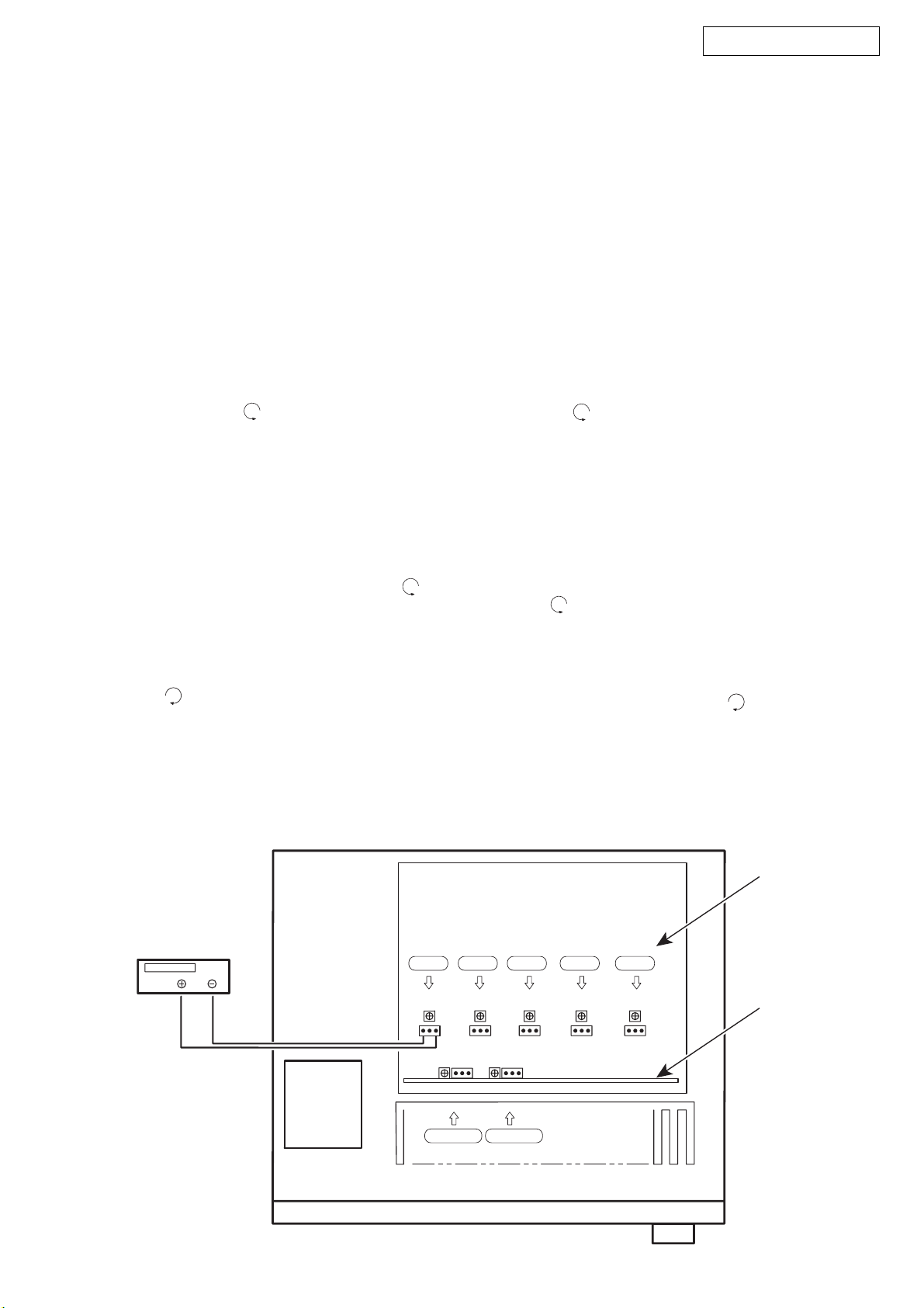
Idling Current
Required measurement equipment: DC Voltmeter
1. Preparation
(1) Avoid direct blow from an air conditioner or an electric
fan, and adjust the unit at normal room temperature 15 °C
~ 30 °C (59 °F ~ 86 °F).
(2) Presetting
• POWER (Power source switch) OFF
• SPEAKER (Speaker terminal) No load
(Do not connect speaker, dummy resistor, etc.)
2. Adjustment
(1) Remove top cover and set VR101 FL, FR, C, SL, SR, on
Main Amp. Unit, VR401, VR402 on 2ch- Amp. Unit at fully
counterclockwise ( ) position.
(2) Connect DC Voltmeter to test points (FRONT-Lch:
TP101, FRONT-Rch: TP105, CENTER ch: TP103, SURROUND-Lch: TP102, SURROUND-Rch: TP104, SURROUND-BACK Lch: TP401, SURROUND-BACK Rch:
TP402).
(3) Connect power cord to AC Line, and turn power switch
"ON".
(4) Presetting.
MASTER VOLUME : "---" counterclockwise ( min.)
SPEAKER (Speaker terminal) : No load
(Do not connect speaker, dummy resistor, etc.)
MODE : 7CH STEREO
FUNCTION : CD
(5) Within 2 minutes after the power on, turn VR101 clock-
wise ( ) to adjust the TEST POINT voltage to
1.5 mV ± 0.5 mV DC.
(6) After 10 minutes from the preset above, turn VR101 to
set th e vol tage to
2.0 mV ± 0.5 mV DC.
(7) Adjust the Variable Resistors of other channels in the
same way.
調整
オーディオセクション
アイドリング電流の調整
調整に必要な測定器 : DCVoltmeter
1. 準備
(1) セットをクーラ、扇風機のそばなど風通しの良い場所
を避け、通常の使用状態に置きます。セットの周囲温
度は 15〜30 ℃、湿度は常湿とします。
(2) プリセット
・電源スイッチ OFF
・スピーカ端子 無負荷
( スピーカ・ダミー抵抗器などを接続しない。)
2. 調整
(1) 上カバーをはずし、メインアンプ基板の VR101FL,FR,
C,SL,SR 及び 2ch- アンプ基板の VR401,VR402 を反時計
方向 ( )に回し切った状態にセットします。
(2) テストポイント (FRONT-Lch:TP101,FRONT-Rch:
TP105,CENTERch:TP103,SURROUND-Lch:TP102,
SURROUND-Rch:TP104,SURROUND-BACKLch:TP401,
SURROUND-BACKRch:TP402) に DCVoltmeterを接続
します。
(3) 電源コードを AC100V(95〜105Vの範囲でも可)に接
続し、電源スイッチを "ON"にします。
(4) ON後、次のようにセットします。
・MASTERVOLUME(音量調節つまみ)→反時計方向
( )に回す、最小の状態にする。
・SPEAKER(スピーカ端子)→無負荷(スピーカ、
ダミー抵抗器などを接続しない。)
MODE:7CHSTEREO
FUNCTION:CD
(5) 2分以内に VR101を時計方向 ( ) に回しテストポイ
ントの電圧を次のように調整します。
1.5mV ±0.5mVDC
(6) 予備調整から 10分後 VR101を回し、次のように電圧を
設定します。
2.0mV± 0.5mVDC
(7) 同じ方法で各チャネルの可変抵抗を調整します。
DC Voltmeter
F Lch
VR101FL
VR401
S Back Lch
TP101
TP401
S Lch
VR101SL
TP102
VR402
S Back Rch
7
TP402
C ch
VR101C
TP103
S Rch
VR101SR
TP104
F Rch
VR101FR
TP105
MAIN AMP. UNIT
2CH AMP. UNIT
Page 8
AVR-1908 / AVR-788
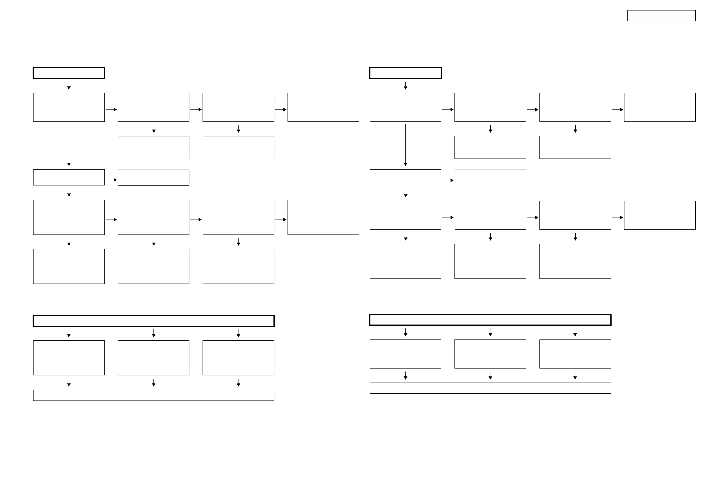
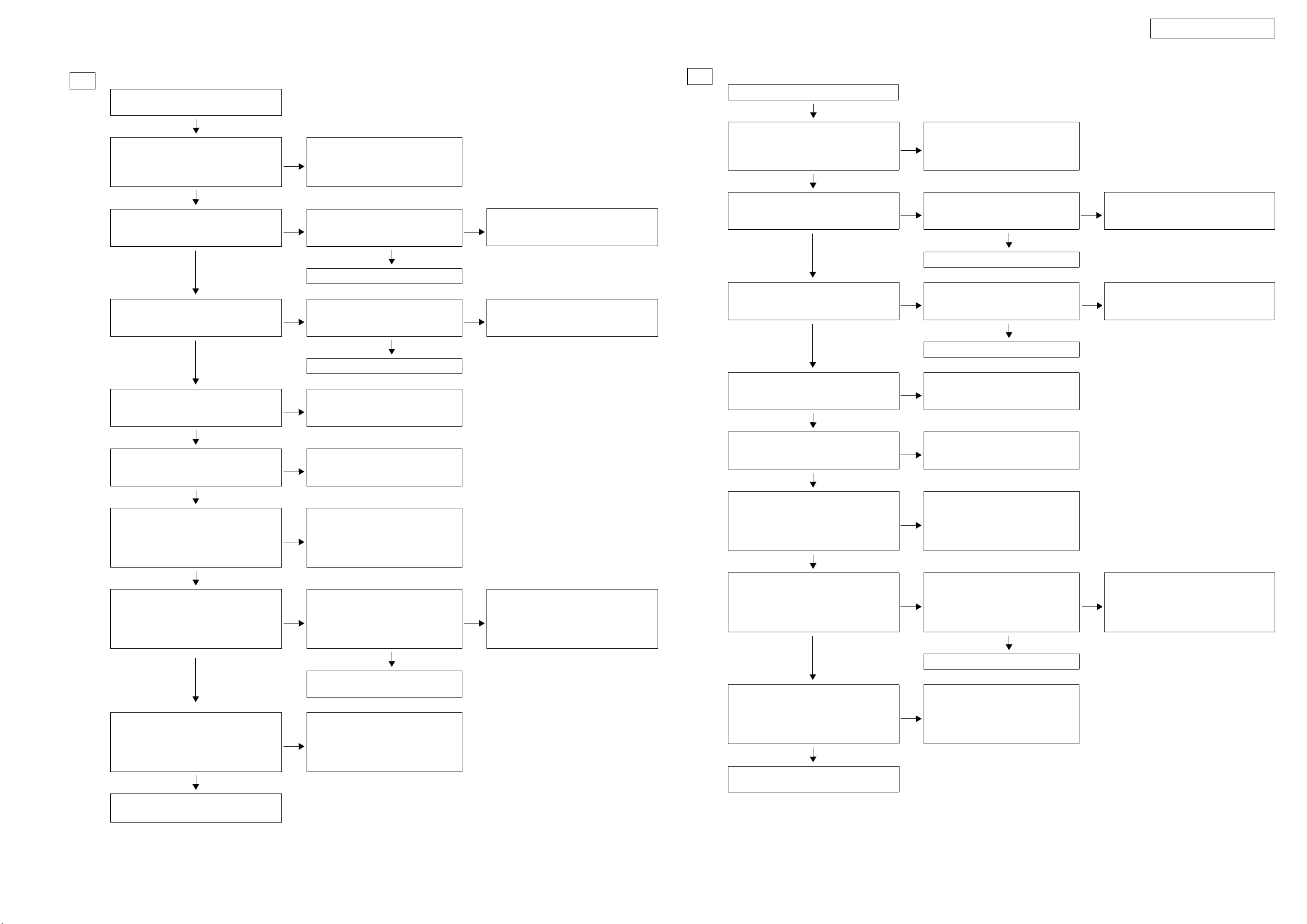
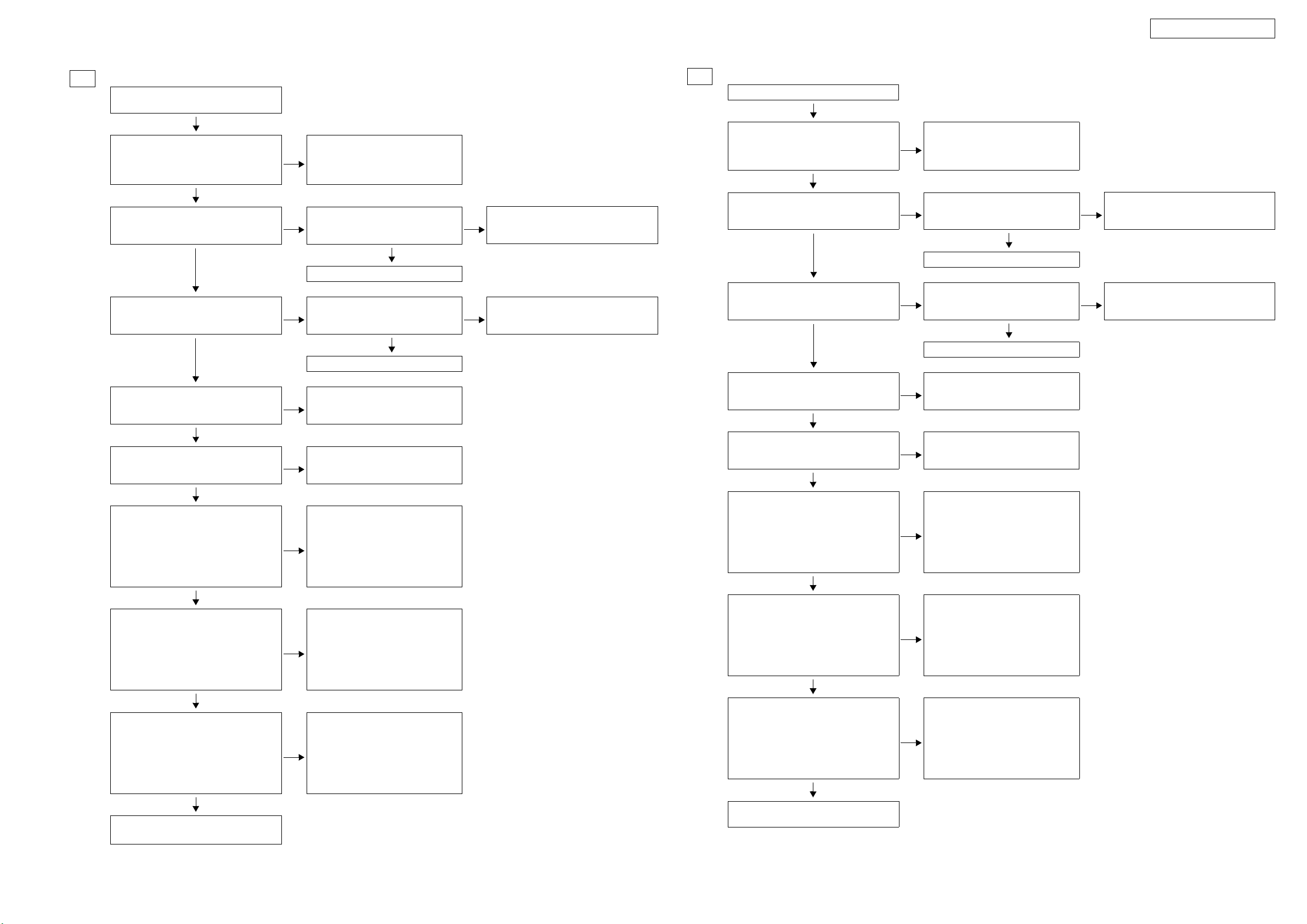
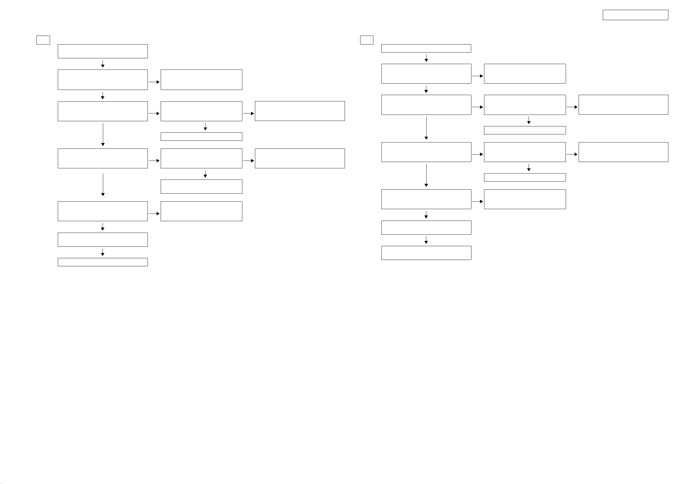
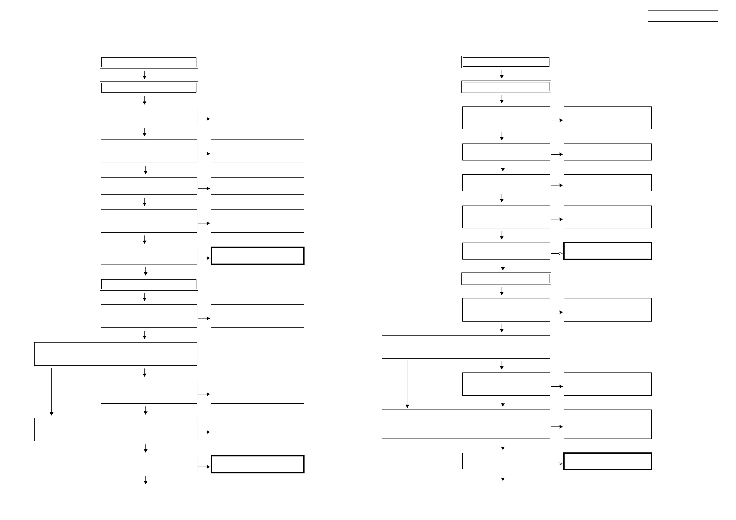
TROUBLE SHOOTING
1. POWER
1.1. Power not turn on
Power not turn on
Is the ON/STANDBY indicator
on the front panel flashing red?
YES
Is the fuse blown?
YES
Does the power turn on when
the POWER switch is turned off
then back on?
YES YES YES
Check the primary circuitry
parts including the POWER
switch (for poor contacts, etc.),
and replace any defective
parts.
NO
NO
NO
Are there any incomplete connections in the connectors connecting between the various
circuit boards?
YES YES
Connect the connectors properly.
Refer to 1.2.Fuse is blown
Is a DC 6V voltage being supplied from the POWER B’d
(CN505 pins 3 and 4) to the
microprocessor?
Check the microprocessor
periphery circuitry and replace
any defective parts.
Is there a short circuit between
NO
the speaker terminals and the
ground?
Check for damage in the power
amplifier circuitry parts and
replace any defective parts.
Is a DC 6V voltage output when
the cord supplying the power
NO
from the SUPPLY B’d to the
microprocessor (CN511) is
unplugged?
Check the circuitry and parts
from CN511 on the SUPPLY
B’d to the microprocessor for
damage and short-circuits, and
replace any defective parts.
Correct the short circuit
NO
between the speaker and the
ground.
Check the parts from IC807 to
NO
the primary circuitry and
replace any defective parts.
トラブルシューティング
1. 電源
1.1. 電源が入らない
電源が入らない
フロントパネルの
ON/STANDBY インジ
ケータが赤色点滅しています
か?
YES
ヒューズは断線していません
か?
YES
POWERSW を OFF にして、再
度 POWERSW を ON にすると
電源が入りますか?
YES YES YES
POWERSW等を含む 1 次回路部
品 ( 接触不良等 ) を確認し、不
良部品を交換してください。
NO
NO
NO
各基板間を接続しているコネ
クターに不完全な接続部分は
ありますか?
YES YES
コネクターを正しく接続して
ください。
1.2. ヒューズが断線しているを
参照してください。
POWER 基板(CN505 の 3、4番
ピン)からマイコンに DC6V が
供給されていますか?
マイコン周辺回路を確認し、不
良部品を交換してください。
NO
SP 端子と GND 間が短絡してい
ますか?
POWERAMP 回路の部品の破損
を確認し、不良部品を交換して
ください。
SUPPLY 基板からマイコンヘ電
NO
源を供給しているコード
(CN511)を抜いて DC6V が出
力されていますか?
SUPPLY 基板の CN511 以降か
らマイコン電源までの回路お
よび部品の破損や短絡を確認
し、不良部品を交換してくだ
さい
NO
SP 端子と GND 間の短絡を取り
除いてください。
IC807 〜 1 次回路までの部品を
NO
確認し、不良部品を交換してく
ださい。
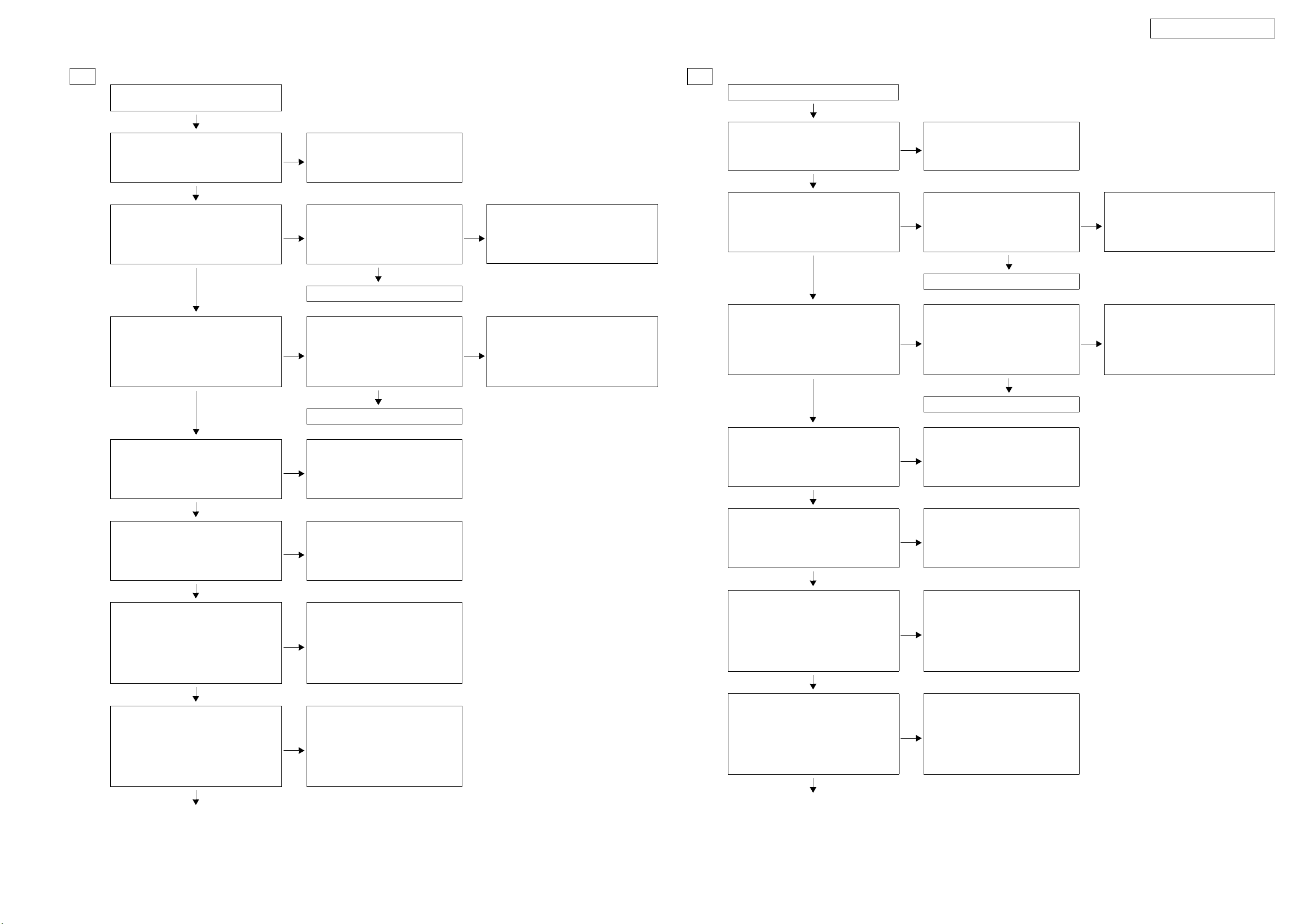
1.2. Fuse is blown
Check for leaks or short circuits
in the primary side parts, and
replace any defective parts.
Fuse is blown
Check for short circuits in the
rectifier diodes and circuitry of
the secondary side rectifying
circuits, and replace any defective parts.
After repairing, also replace the fuse.
Check for short circuits in the
power stabilizer unit's regulator output terminal and the
ground, and replace any defective parts.
1.2. ヒューズが断線している
1 次側の部品にリークまたは短
絡を確認し、不良部品を交換し
てください。
ヒューズが断線している
2 次側のそれぞれの整流回路
で、整流ダイオードおよび回路の
短絡を確認し、不良部品を交換
してください。
修理後、FUSE も交換してください。
電源安定化部のレギュレータ
の出力端子と GND の短絡を確
認し、短絡している場合は、不
良部品を交換してくだい。
8
Page 9
AVR-1908 / AVR-788
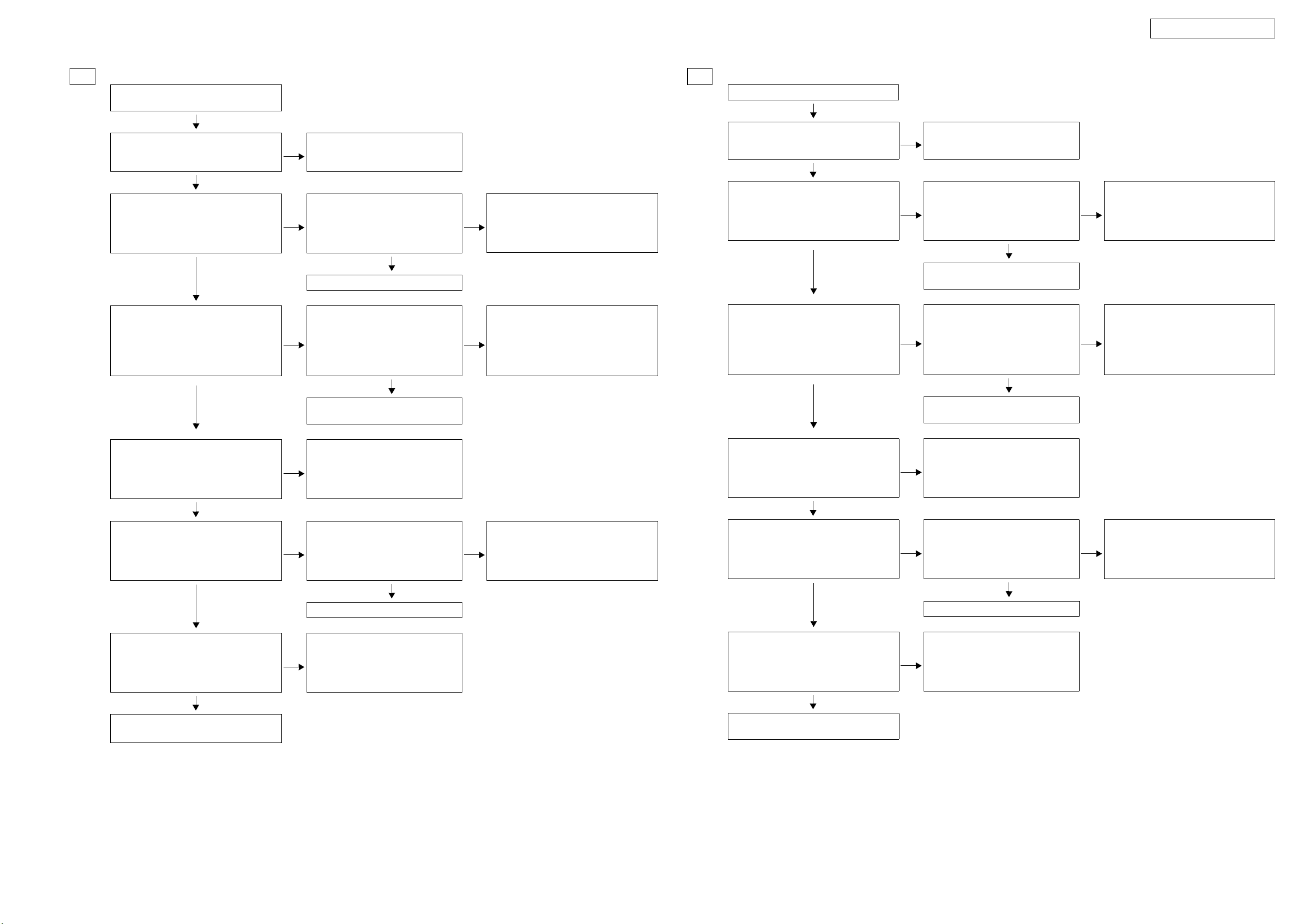
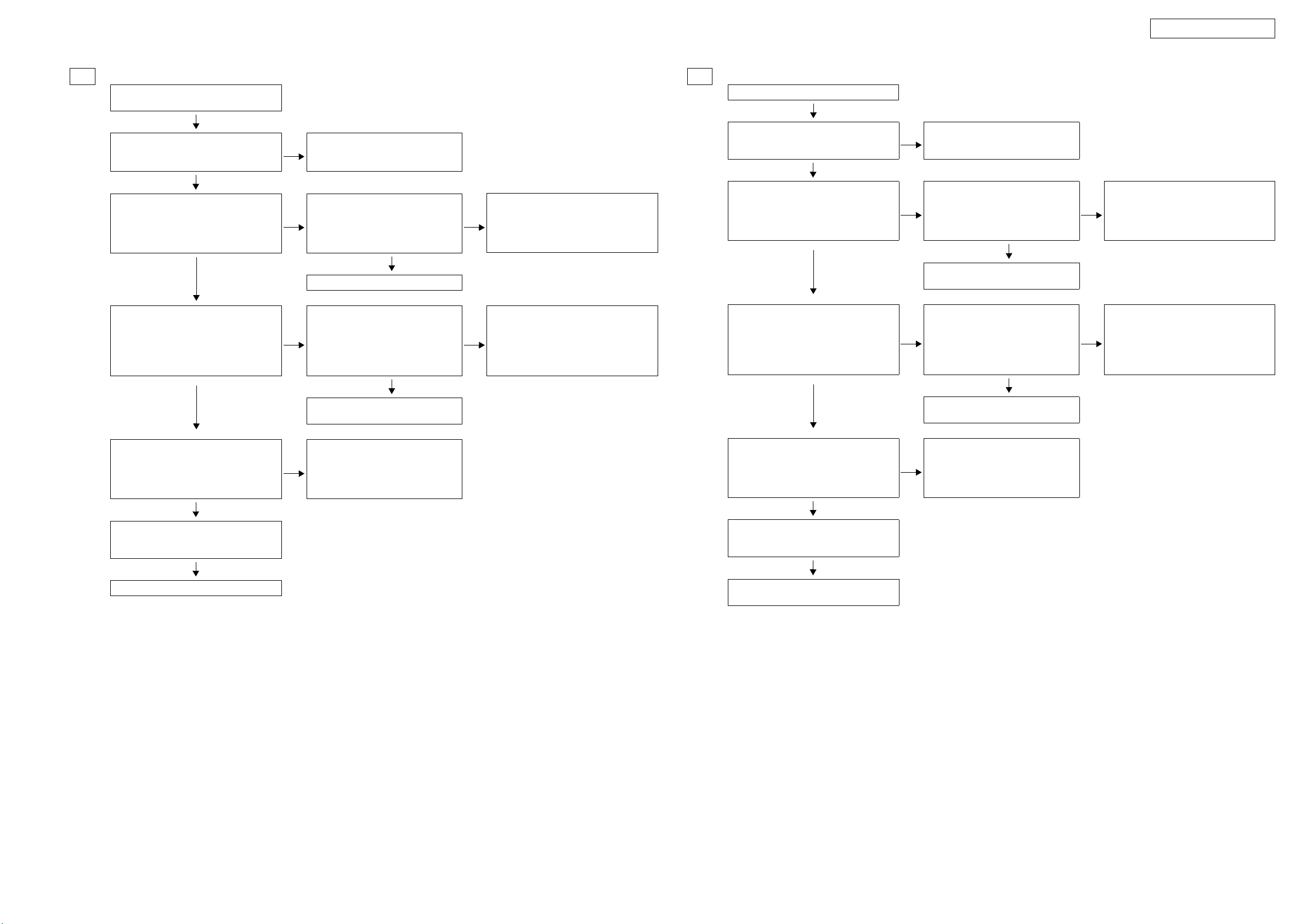
2. Analog video
2.1. MONITOR OUT (CVBS) output NG
Video convert ON
Input
CVBS
A B No output A No output No output
Input
S
MONITOR OUT (CVBS) output NG
Checking the video convert ON/OFF settings
Input
COMPONENT
Input
CVBS
※ When checking operation, select
DVD for the function.
(COMPONENT1 input)
Video convert OFF
Input
S
COMPONENT
I n p u t
2. アナログビデオ
2.1. MONITOROUT(CVBS)出力NG
ビデオコンバートON ビデオコンバートOFF
入力
CVBS
Aへ Bへ 出力されません Aへ 出力されません 出力されません
入力
S
MONITOROUT(CVBS)出力NG ※ 動作を確認する時はファンクショ
ビデオコンバートON/OFFの設定確認
入力
COMPONENT
入力
CVBS
ンを DVD に選択してください。
(COMPONENT1入力 )
入力
S
入力
COMPONENT
9
Page 10
AVR-1908 / AVR-788
A
Input
CVBS
Check ± 5V.
+5V: CP706 / 2pin
-5V: CP706 / 3pin
OK
Check input/output of video SW.
Input : C2002 /12pin
Output : C2002 / 1pin
OK
Check input/output of MPX.
Input : C2007 / 1pin
Output : IC2007 / 15pin
OK
Check input/output of MPX.
Input : IC2005 / 2pin
Output : IC2007 / 3pin
OK
To troubleshooting 1.1 Power not turn
NG
on.
NG
NG
NG
Check video SW settings.
IC2002 - 15pin: H
IC2002 - 11pin: L
OK
Check soldering of IC2002.
Check MPX settings.
IC2007 - 9pin: H
IC2007 - 10pin: L
OK
Check soldering of IC2007.
Check MPX settings.
IC2005 - 9pin: H
IC2005 - 10pin: L
OK
Check soldering of IC2005.
NG
NG
NG
Check soldering of IC2003.
Check soldering of IC2003.
Check soldering of IC2004.
A
入力(CVBS)
±5Vの確認
+5V:CP706/2pin
-5V:CP706/3pin
OK
ビデオSW の入出力確認
入力 :IC2002/12pin
出力 :IC2002/1pin
OK
MPX の入出力確認
入力 :IC2007/1pin
出力 :IC2007/15pin
OK
MPX の入出力確認
入力 :IC2005/2pin
出力 :IC2007/3pin
OK
NG
1.1 電源が入らないのトラブルシューティングへ
NG
NG
NG
ビデオSW の設定確認
IC2002-15pin:H
IC2002-11pin:L
OK
IC2002 のハンダ付け確認
MPX の設定確認
IC2007-9pin:H
IC2007-10pin:L
OK
IC2007 のハンダ付け確認
MPX の設定確認
IC2005- 9pin:H
IC2005-10pin:L
OK
IC2005 のハンダ付け確認
NG
NG
NG
IC2003 のハンダ付け確認
IC2003 のハンダ付け確認
IC2004 のハンダ付け確認
Check input/output of AMP.
Input : IC2000 / 3pin
Output : IC2000 / 1pin
OK
Check a cable between the main unit -
monitor or the monitor.
※ Unless specified, VIDEO UNIT part.
NG
Check soldering of IC2000.
AMP の入出力確認
入力 :IC2000/3pin
出力 :IC2000/1pin
OK
本体 - モニター間のケーブル
もしくは、モニターの確認
NG
※ 特に記載がない場合は VIDEO基板の部品です。
IC2000 のハンダ付け確認
10
Page 11
AVR-1908 / AVR-788
B
Input
S
Check ± 5V.
+5V : CP706 / 2pin
-5V : CP706 / 3pin
OK
Check input/output of video SW.
Input Y : IC2011 / 12pin
Input C : IC2012 / 12pin
Output Y : IC2011 / 1pin
Output C : IC2012 / 1pin
OK
Check input/output of MPX.
Input Y : IC2007 / 5pin
Input C : IC2008 / 12pin
Output Y : IC2007 / 4pin
Output C : IC2008 / 14pin
OK
To troubleshooting 1.1 Power not turn
NG
on.
Check video SW settings.
NG
Check soldering of IC2011 and IC2012.
NG
Check soldering of IC2007 and IC2008.
IC2011 - 15pin: H
IC2011 - 11pin: L
IC2012 - 15pin: H
IC2012 - 11pin: L
OK
Check MPX settings.
IC2007 - 9pin: L
IC2007 - 10pin: L
IC2008 - 9pin: L
IC2008 - 10pin: L
IC2008 - 11pin: L
OK
NG
NG
Check soldering of IC2003.
Check soldering of IC2001 and IC2003.
B
入力(S)
±5Vの確認
+5V:CP706/2pin
-5V:CP706/3pin
OK
ビデオSW の入出力確認
入力 Y:IC2011/12pin
入力 C:IC2012/12pin
出力 Y:IC2011/1pin
出力 C:IC2012/1pin
OK
MPX の入出力確認
入力 Y:IC2007/5pin
入力 C:IC2008/12pin
出力 Y:IC2007/4pin
出力 C:IC2008/14pin
OK
NG
1.1 電源が入らないのトラブルシューティングへ
ビデオSW の設定確認
NG
NG
IC2011-15pin:H
IC2011-11pin:L
IC2012-15pin:H
IC2012-11pin:L
OK
IC2011,2012 の
ハンダ付け確認
MPX の設定確認
IC2007-9pin:L
IC2007-10pin:L
IC2008-9pin:L
IC2008-10pin:L
IC2008-11pin:L
OK
IC2007,2008 の
ハンダ付け確認
NG
NG
IC2003 のハンダ付け確認
IC2001,2003 の
ハンダ付け確認
Check input/output of AMP
Input Y : IC2009 / 5pin
Input C : IC2009 / 3pin
Output Y : C2009 / 7pin
Output C : IC2009 / 1pin
OK
Check input/output of MPX.
Input : IC2005 / 4pin
Output : IC2007 / 3pin
OK
Check input/output of AMP.
Input : IC2000 / 3pin
Output : IC2000 / 1pin
OK
Check a cable between the main unit -
monitor or the monitor.
※ Unless specified, VIDEO UNIT part.
NG
NG
NG
Check soldering of IC2009.
Check MPX settings.
IC2014 - 9pin: H
IC2014 - 10pin: H
OK
Check soldering of
Check soldering of IC2013.
IC2014
AMP の入出力確認
入力 Y:IC2009/5pin
入力 C:IC2009/3pin
出力 Y:IC2009/7pin
出力 C:IC2009/1pin
OK
NG
.
Check soldering of IC2004.
MPX の入出力確認
入力 :IC2005/4pin
出力 :IC2007/3pin
OK
AMP の入出力確認
入力 :IC2000/3pin
出力 :IC2000/1pin
OK
本体 - モニター間のケーブル
もしくは、モニターの確認
NG
NG
NG
IC2009 のハンダ付け確認
MPX の設定確認
IC2014-9pin:H
IC2014-10pin:H
OK
IC2014 のハンダ付け確認
IC2013 のハンダ付け確認
NG
IC2004 のハンダ付け確認
※ 特に記載がない場合は VIDEO基板の部品です。
11
Page 12
AVR-1908 / AVR-788
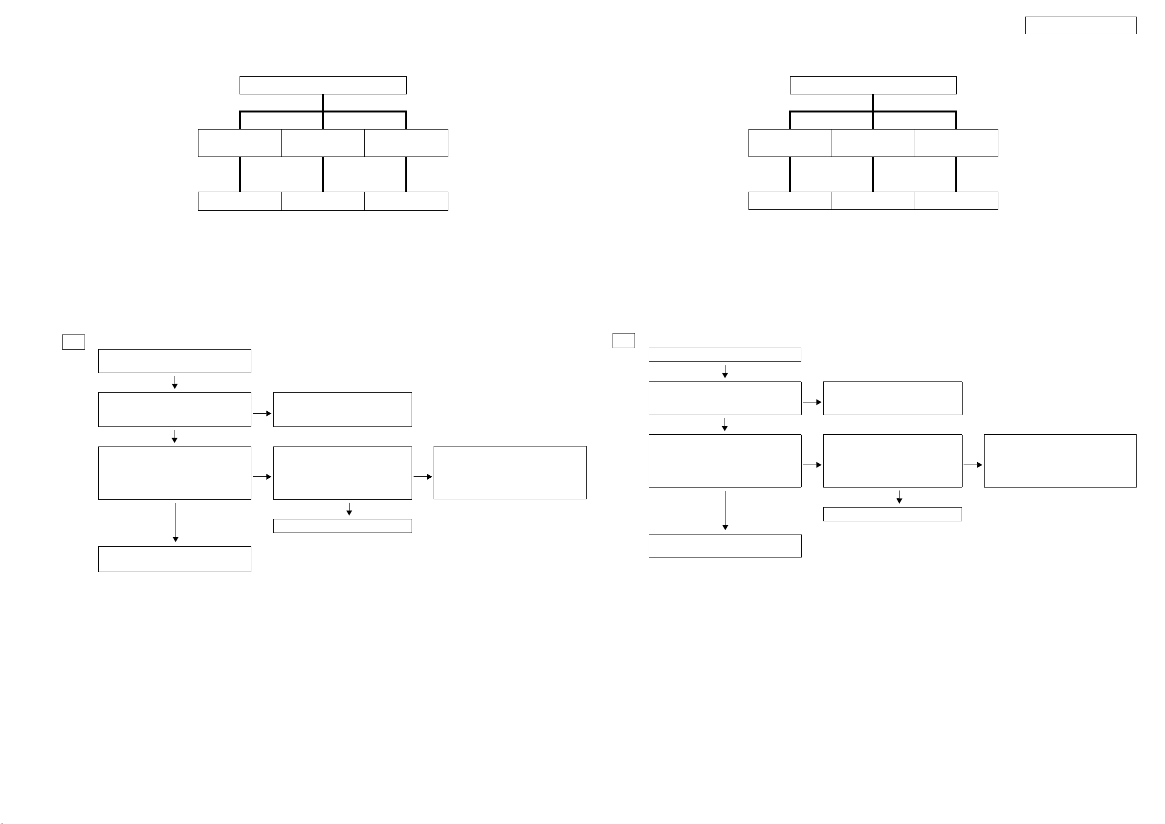
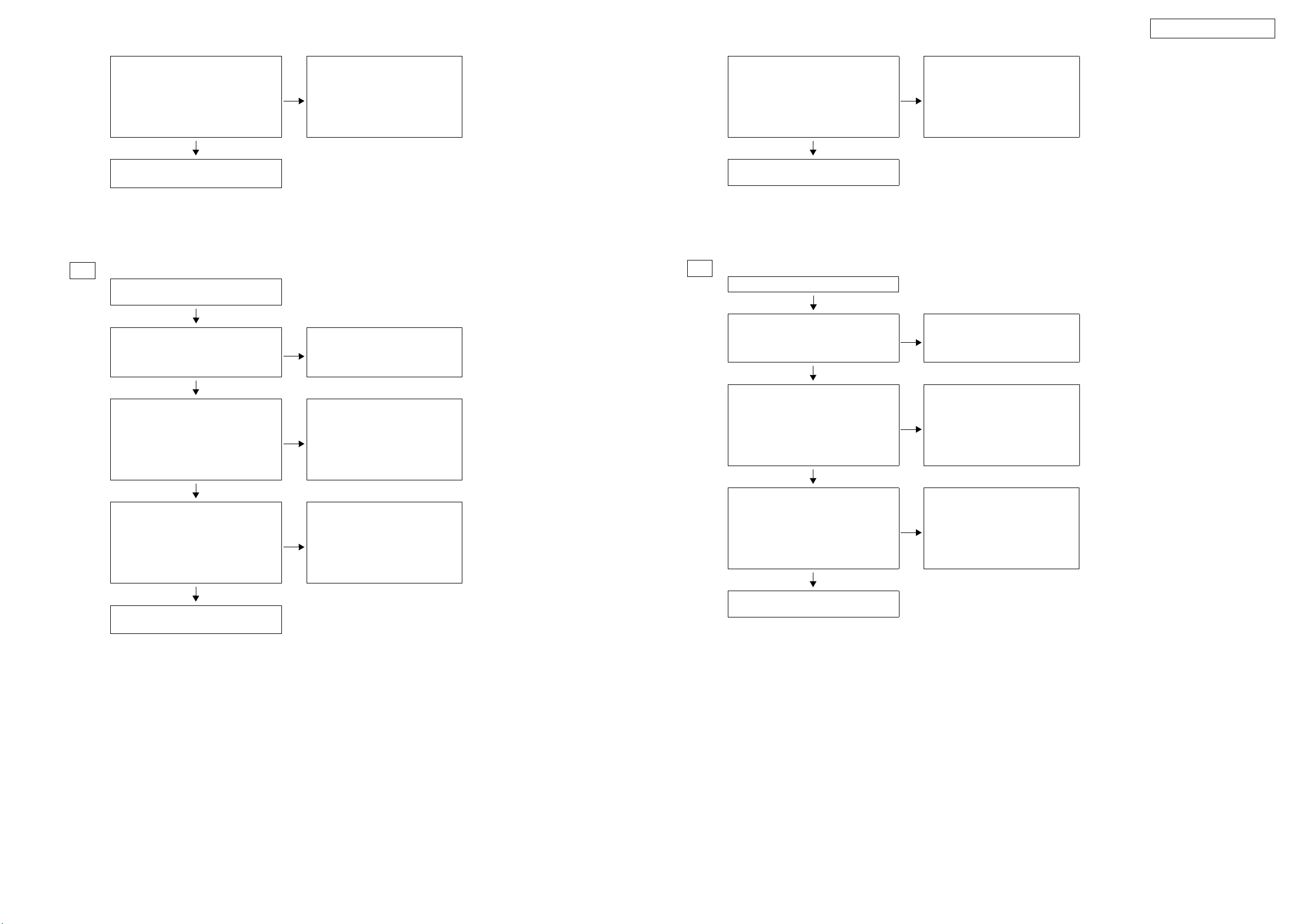
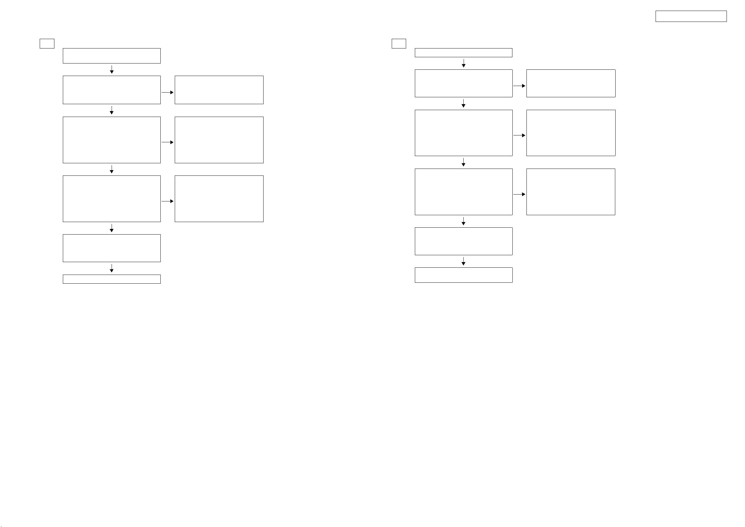
2.2. VCR MONITOR OUT(CVBS) Output NG
VCR/DVR MONITOR OUT(CVBS) Output NG.
I n p u t
CVBS
VCR : C No output No output
Input
S
Input
COMPONENT
※ When checking operation, select
DVD for the function.
2.2. VCRMONITOROUT(CVBS) 出力 NG
VCR:C 出力されません 出力されません
VCR/DVRMONITOROUT(CVBS) 出力 NG ※ 動作を確認する時はファンクショ
入力
CVBS
入力
S
入力
COMPONENT
ンを DVD に選択してください。
C
Input
CVBS
Check ± 5V.
+5V : CP706 / 2pin
-5V : CP706 / 3pin
OK
Check input/output of video SW.
Input : IC2002 / 12pin
Output : IC2002 / 14pin
OK
Check
a cable between the main unit -
monitor or the monitor.
※ Unless specified, VIDEO UNIT part.
To troubleshooting 1.1 Power not turn
NG
on.
NG
Check video SW settings.
IC2002 - 8pin: L
IC2002 - 9pin: H
OK
Check soldering of IC2002.
NG
Check soldering of IC2003.
C
入力(CVBS)
±5Vの確認
+5V:CP706/2pin
-5V:CP706/3pin
OK
ビデオSW の入出力確認
入力 :IC2002/12pin
出力 :IC2002/14pin
OK
本体 - モニター間のケーブル
もしくは、モニターの確認
※ 特に記載がない場合は VIDEO基板の部品です。
NG
1.1 電源が入らないのトラブルシューティングへ
NG
ビデオSW の設定確認
IC2002-8pin:L
IC2002-9pin:H
OK
IC2002 のハンダ付け確認
NG
IC2003 のハンダ付け確認
12
Page 13
AVR-1908 / AVR-788
2.3. MONITOR OUT (S) Output NG
Video convert ON Video convert OFF
Input
CVBS
D E No output No output E No output
Input
S
MONITOR OUT (S) Output NG
Checking the video convert ON/OFF settings
Input
COMPONENT
Input
CVBS
※ When checking operation, select
DVD for the function.
(COMPONENT1 Input)
Input
S
I n p u t
COMPONENT
2.3. MONITOROUT(S)出力 NG
ビデオコンバートON ビデオコンバートOFF
入力
CVBS
D へ E へ 出力されません 出力されません E へ 出力されません
入力
S
MONITOROUT(S)出力 NG ※ 動作を確認する時はファンクショ
ビデオコンバートON/OFFの設定確認
入力
COMPONENT
入力
CVBS
ンを DVD に選択してください。
(COMPONENT1入力 )
入力
S
入力
COMPONENT
13
Page 14
AVR-1908 / AVR-788
D
Input
CVBS
Check ± 5V.
+5V: CP706 / 2pin
-5V: CP706 / 3pin
+9V: CP706 / 1pin
OK
Check input/output of video SW.
Input : IC2002 / 12pin
Output : IC2002 / 1pin
OK
Check input/output of MPX.
Input : IC2007 / 1pin
Output : IC2007 / 15pin
OK
Check input/output of AMP.
Input : IC2010 / 5pin
Output : IC2010 / 7pin
OK
Check input/output of video driver.
Input : IC2017 / 5pin
Output : IC2017 / 7pin
OK
Check input/output of video driver.
Input Y : IC2016 / 8pin
Input C : IC2016 / 4pin
Output Y : IC2016 / 27pin
Output C : IC2016 / 32pin
OK
Check input/output of MPX.
Input Y : IC2014 / 5pin
Input C : IC2014 / 14pin
Output Y : IC2014 / 3pin
Output C : IC2014 / 13pin
To troubleshooting 1.1 Power not turn
NG
on.
NG
NG
NG
NG
NG
NG
Check video SW settings.
IC2002 - 15pin: H
IC2002 - 11pin: L
OK
Check soldering of IC2002.
Check MPX settings.
IC2007 - 9pin: H
IC2007 - 10pin: L
OK
Check soldering of IC2007.
Check soldering of IC2010.
Check soldering of IC2017.
Check soldering of IC2016.
Check MPX settings.
IC2014 - 9pin: L
IC2014 - 10pin: H
OK
NG
NG
NG
Check soldering of IC2003.
Check soldering of IC2003.
Check soldering of IC2004.
D
入力(CVBS)
± 5V,+9V の確認
+5V:CP706/2pin
-5V:CP706/3pin
+9V:CP706/1pin
OK
ビデオSW の入出力確認
入力 :IC2002/12pin
出力 :IC2002/1pin
OK
MPX の入出力確認
入力 :IC2007/1pin
出力 :IC2007/15pin
OK
AMP の入出力確認
入力 :IC2010/5pin
出力 :IC2010/7pin
OK
ビデオドライバの入出力確認
入力 :IC2017/5pin
出力 :IC2017/7pin
OK
ビデオドライバの入出力確認
入力 Y:IC2016/8pin
入力 C:IC2016/4pin
出力 Y:IC2016/27pin
出力 C:IC2016/32pin
OK
MPX の入出力確認
入力 Y:IC2014/5pin
入力 C:IC2014/14pin
出力 Y:IC2014/3pin
出力 C:IC2014/13pin
OK
NG
1.1 電源が入らないのトラブルシューティングへ
NG
NG
NG
NG
NG
NG
ビデオSW の設定確認
IC2002-15pin:H
IC2002-11pin:L
OK
IC2002 のハンダ付け確認
MPX の設定確認
IC2007-9pin:H
IC2007-10pin:L
OK
IC2007 のハンダ付け確認
IC2010 のハンダ付け確認
IC2017 のハンダ付け確認
IC2016 のハンダ付け確認
MPX の設定確認
IC2014-9pin:L
IC2014-10pin:H
OK
IC2014 のハンダ付け確認
NG
NG
NG
IC2003 のハンダ付け確認
IC2003 のハンダ付け確認
IC2004 のハンダ付け確認
OK
Check input/output of AMP.
Input Y: IC2013 / 3pin
Input C: IC2013 / 5pin
Output Y : IC2013 / 1pin
Output C : IC2013 / 7pin
OK
Check a cable between the main unit -
monitor or the monitor.
※ Unless specified, VIDEO UNIT part.
NG
Check soldering of IC2014.
Check soldering of IC2013.
14
AMP の入出力確認
入力 Y:IC2013/3pin
入力 C:IC2013/5pin
出力 Y:IC2013/1pin
出力 C:IC2013/7pin
OK
本体 - モニター間のケーブル
もしくは、モニターの確認
NG
※ 特に記載がない場合は VIDEO基板の部品です。
IC2013 のハンダ付け確認
Page 15
AVR-1908 / AVR-788
E
Input
S
Check ± 5V.
+5V : CP706 / 2pin
-5V : CP706 / 3pin
OK
Check input/output of video SW.
Input Y : IC2011 / 12pin
Input C : IC2012 / 12pin
Output Y : IC2011 / 1pin
Output C : IC2012 / 1pin
OK
Check input/output of MPX.
Input Y : IC2007 / 5pin
Input C : IC2008 / 12pin
Output Y : IC2007 / 4pin
Output C : IC2008 / 14pin
OK
Check input/output of AMP.
Input Y : IC2009 / 5pin
Input C : IC2009 / 3pin
Output Y : IC2009 / 7pin
Output C : IC2009 / 1pin
To troubleshooting 1.1 Power not turn
NG
on.
Check video SW settings.
NG
Check soldering of
NG
Check soldering of
IC
NG
IC2011 - 15pin: H
IC2011 - 11pin: L
IC2012 - 15pin: H
IC2012 - 11pin: L
OK
IC2011
Check MPX settings.
IC2007 - 9pin: L
IC2007 - 10pin: L
IC2008 - 9pin: L
IC2008 - 10pin: L
IC2008 - 11pin: L
OK
IC2007
2008
.
Check soldering of IC2009.
and IC
and
2012
NG
.
NG
Check soldering of IC2003.
Check soldering of IC2001 and IC2003.
E
入力(S)
±5Vの確認
+5V:CP706/2pin
-5V:CP706/3pin
OK
ビデオSW の入出力確認
入力 Y:IC2011/12pin
入力 C:IC2012/12pin
出力 Y:IC2011/1pin
出力 C:IC2012/1pin
OK
MPX の入出力確認
入力 Y:IC2007/5pin
入力 C:IC2008/12pin
出力 Y:IC2007/4pin
出力 C:IC2008/14pin
OK
AMP の入出力確認
入力 Y:IC2009/5pin
入力 C:IC2009/3pin
出力 Y:IC2009/7pin
出力 C:IC2009/1pin
NG
1.1 電源が入らないのトラブルシューティングへ
ビデオSW の設定確認
NG
NG
NG
IC2011-15pin:H
IC2011-11pin:L
IC2012-15pin:H
IC2012-11pin:L
OK
IC2011,2012 の
ハンダ付け確認
MPX の設定確認
IC2007-9pin:L
IC2007-10pin:L
IC2008-9pin:L
IC2008-10pin:L
IC2008-11pin:L
OK
IC2007,2008 の
ハンダ付け確認
IC2009 のハンダ付け確認
NG
NG
IC2003 のハンダ付け確認
IC2001,2003 の
ハンダ付け確認
OK
Check input/output of MPX.
Input Y : IC2014 / 2pin
Input C : IC2014 / 15pin
Output Y : IC2014 / 3pin
Output C : IC2014 / 13pin
OK
Check input/output of AMP.
Input Y : IC2013 / 3pin
Input C : IC2013 / 5pin
Output Y : IC2013 / 1pin
Output C : IC2013 / 7pin
OK
Check a cable between the main unit -
monitor or the monitor.
※ Unless specified, VIDEO UNIT part.
NG
NG
Check MPX settings.
IC2014 - 9pin: H
IC2014 - 10pin: L
OK
Check soldering of
Check soldering of IC2013.
IC2014
OK
MPX の入出力確認
NG
.
Check soldering of IC2004.
入力 Y:IC2014/2pin
入力 C:IC2014/15pin
出力 Y:IC2014/3pin
出力 C:IC2014/13pin
OK
AMP の入出力確認
入力 Y:IC2013/3pin
入力 C:IC2013/5pin
出力 Y:IC2013/1pin
出力 C:IC2013/7pin
OK
本体 - モニター間のケーブル
もしくは、モニターの確認
NG
NG
MPX の設定確認
IC2014-9pin:H
IC2014-10pin:L
OK
IC2014 のハンダ付け確認
IC2013 のハンダ付け確認
NG
IC2004 のハンダ付け確認
※ 特に記載がない場合は VIDEO基板の部品です。
15
Page 16
AVR-1908 / AVR-788
2.4. VCR MONITOR OUT(S) Output NG
I n p u t
CVBS
No output VCR : F No output
VCR/DVR MONITOR OUT(S) Output NG.
Input
S
COMPONENT
Input
※ When checking operation, select
DVD for the function.
2.4. VCRMONITOROUT(S) 出力 NG
VCR/DVRMONITOROUT(S) 出力 NG ※ 動作を確認する時はファンクショ
入力
CVBS
出力されません VCR:F 出力されません
入力
S
入力
COMPONENT
ンを DVD に選択してください。
F
Input
S
Check ± 5V.
+5V : CP706 / 2pin
-5V : CP706 / 3pin
OK
Check input/output of video SW.
Input Y : IC2011 / 12pin
Input C : IC2012 / 12pin
Output Y : IC2011 / 1pin
Output C : IC2012 / 1pin
OK
Check a cable between the main unit -
monitor or the monitor.
※ Unless specified, VIDEO UNIT part.
To troubleshooting 1.1 Power not turn
NG
on.
Check video SW settings.
NG
IC2011 - 8pin: L
IC2011 - 9pin: H
IC2012 - 8pin: L
IC2012 - 9pin: H
OK
Check soldering of
IC2002
F
入力(S)
±5Vの確認
+5V:CP706/2pin
-5V:CP706/3pin
OK
ビデオSW の入出力確認
入力 Y:IC2011/12pin
NG
.
Check soldering of IC2003.
入力 C:IC2012/12pin
出力 Y:IC2011/1pin
出力 C:IC2012/1pin
OK
本体 - モニター間のケーブル
もしくは、モニターの確認
NG
1.1 電源が入らないのトラブルシューティングへ
ビデオSW の設定確認
NG
IC2011-8pin:L
IC2011-9pin:H
IC2012-8pin:L
IC2012-9pin:H
OK
IC2002 のハンダ付け確認
NG
IC2003 のハンダ付け確認
※ 特に記載がない場合は VIDEO基板の部品です。
16
Page 17
AVR-1908 / AVR-788
2.5. COMPONENTOUT1,2OutputNG
Video convert ON Video convert OFF
Input
CVBS
G H I No output No output I
Input
S
AVR-1908E3Only
COMPONENT OUT 1,2 Output NG.
Checking the video convert ON/OFF settings.
Input
COMPONENT
Input
CVBS
※ When checking operation, select
DVD for the function.
(COMPONENT1 Input)
Input
S
I n p u t
COMPONENT
2.5. COMPONENTOUT1,2出力 NG
ビデオコンバートON ビデオコンバートOFF
入力
CVBS
G へ H へ I へ 出力されません 出力されません I へ
入力
S
AVR-1908E3 のみ
COMPONENTOUT1,2出力 NG ※ 動作を確認する時はファンクショ
ンを DVD に選択してください。
(COMPONENT1入力 )
ビデオコンバートON/OFFの設定確認
入力
COMPONENT
入力
CVBS
入力
S
入力
COMPONENT
17
Page 18
AVR-1908 / AVR-788
G
Input
CVBS
Check ± 5V and +9V.
+5V : CP706 / 2pin
-5V : CP706 / 3pin
+9V : CP706 / 1pin
OK
Check input/output of video SW.
Input : IC2002 / 12pin
Output : IC2002 / 1pin
OK
Check input/output of MPX.
Input : IC2007 / 1pin
Output : IC2007 / 15pin
OK
Check input/output of AMP
Input : IC2010 / 5pin
Output : IC2010 / 7pin
OK
Check input/output of video driver
Input : IC2017 / 5pin
Output : IC2017 / 7pin
OK
Check imput/output of video driver.
Input Y : IC2016 / 11pin
Input Cb : IC2016 / 13pin
Input Cr : IC2016 / 15pin
Output Y : IC2016 / 24pin
Output Cb : IC2016 / 21pin
Output Cr : IC2016 / 18pin
OK
Check input/output of V-SEL.
Input Y : IC2015 / 36pin
Input Cb : IC2015 / 38pin
Input Cr : IC2015 / 40pin
Output Y : IC2015 / 27pin
Output Cb : IC2015 / 24pin
Output Cr : IC2015 / 21pin
OK
Check input/output of AMP.
Input Y : IC2024 / 1pin
Input Cb : IC2024 / 3pin
Input Cr : IC2024 / 5pin
Output Y : IC2024 / 13pin
Output Cb : IC2024 / 11pin
Output Cr : IC2024 / 9pin
OK
Check a cable between the main unit -
monitor or the monitor.
※ Unless specified, VIDEO UNIT part.
To troubleshooting 1.1 Power not turn
NG
on.
NG
NG
NG
NG
NG
NG
NG
Check video SW settings.
IC2002 - 15pin: H
IC2002 - 11pin: L
OK
Check soldering of IC2002.
Check MPX settings.
IC2007 - 9pin: H
IC2007 - 10pin: L
OK
Check soldering of IC2007.
Check soldering of IC2010.
Check soldering of IC2017.
Check soldering of IC2016.
Check soldering of IC2015.
Check soldering of IC2013.
NG
NG
Check soldering of IC2003.
Check soldering of IC2003.
G
入力(CVBS)
± 5V,+9V の確認
+5V:CP706/2pin
-5V:CP706/3pin
+9V:CP706/1pin
OK
ビデオSW の入出力確認
入力 :IC2002/12pin
出力 :IC2002/1pin
OK
MPX の入出力確認
入力 :IC2007/1pin
出力 :IC2007/15pin
OK
AMP の入出力確認
入力 :IC2010/5pin
出力 :IC2010/7pin
OK
ビデオドライバの入出力確認
入力 :IC2017/5pin
出力 :IC2017/7pin
OK
ビデオドライバの入出力確認
入力 Y:IC2016/11pin
入力 Cb:IC2016/13pin
入力 Cr:IC2016/15pin
出力 Y:IC2016/24pin
出力 Cb:IC2016/21pin
出力 Cr:IC2016/18pin
OK
V-SEL の入出力確認
入力 Y:IC2015/36pin
入力 Cb:IC2015/38pin
入力 Cr:IC2015/40pin
出力 Y:IC2015/27pin
出力 Cb:IC2015/24pin
出力 Cr:IC2015/21pin
OK
AMP の入出力確認
入力 Y:IC2024/1pin
入力 Cb:IC2024/3pin
入力 Cr:IC2024/5pin
出力 Y:IC2024/13pin
出力 Cb:IC2024/11pin
出力 Cr:IC2024/9pin
OK
本体 - モニター間のケーブル
もしくは、モニターの確認
※ 特に記載がない場合は VIDEO基板の部品です。
NG
1.1 電源が入らないのトラブルシューティングへ
NG
NG
NG
NG
NG
NG
NG
ビデオSW の設定確認
IC2002-15pin:H
IC2002-11pin:L
OK
IC2002 のハンダ付け確認
MPX の設定確認
IC2007-9pin:H
IC2007-10pin:L
OK
IC2007 のハンダ付け確認
IC2010 のハンダ付け確認
IC2017 のハンダ付け確認
IC2016 のハンダ付け確認
IC2015 のハンダ付け確認
IC2013 のハンダ付け確認
NG
NG
IC2003 のハンダ付け確認
IC2003 のハンダ付け確認
18
Page 19
AVR-1908 / AVR-788
H
Input
S
Check ± 5V and +9V.
+5V: CP706 / 2pin
-5V: CP706 / 3pin
+9V: CP706 / 1pin
OK
Check input/output of video SW.
Input Y: IC2011 / 12pin
Input C: IC2012 / 12pin
Output Y: IC2011 / 1pin
Output C: IC2012 / 1pin
OK
Check input/output of MPX.
Input Y: IC2007 / 5pin
Input C: IC2008 / 12pin
Output Y: IC2007 / 4pin
Output C: IC2008 / 14pin
OK
To troubleshooting 1.1 Power not turn
NG
on.
Check video SW settings.
NG
NG
IC2011 - 15pin: H
IC2011 - 11pin: L
IC2012 - 15pin: H
IC2012 - 11pin: L
OK
Check soldering of
Check MPX settings.
IC2007 - 9pin: L
IC2007 - 10pin: L
IC2008 - 9pin: L
IC2008 - 10pin: L
IC2008 - 11pin: L
OK
Check soldering of
IC2002
IC2007
NG
Check soldering of IC2003.
.
NG
Check soldering of IC2001 and IC2003.
.
H
入力(S)
± 5V,+9V の確認
+5V:CP706/2pin
-5V:CP706/3pin
+9V:CP706/1pin
OK
ビデオSW の入出力確認
入力 Y:IC2011/12pin
入力 C:IC2012/12pin
出力 Y:IC2011/1pin
出力 C:IC2012/1pin
OK
MPX の入出力確認
入力 Y:IC2007/5pin
入力 C:IC2008/12pin
出力 Y:IC2007/4pin
出力 C:IC2008/14pin
OK
NG
1.1 電源が入らないのトラブルシューティングへ
ビデオSW の設定確
NG
NG
IC2011-15pin:H
IC2011-11pin:L
IC2012-15pin:H
IC2012-11pin:L
OK
IC2002 のハンダ付け確認
MPX の設定確認
IC2007-9pin:L
IC2007-10pin:L
IC2008-9pin:L
IC2008-10pin:L
IC2008-11pin:L
OK
IC2007 のハンダ付け確認
NG
NG
IC2003 のハンダ付け確認
IC2001,2003 の
ハンダ付け確認
Check input/output of AMP.
Input Y: IC2009 / 5pin
Input C: IC2009 / 3pin
Output Y: IC2009 / 7pin
Output C: IC2009 / 1pin
OK
Check input/output of video driver
Input Y: IC2017 / 3pin
Input C: IC2017 / 5pin
Output Y: IC2017 / 1pin
Output C: IC2017 / 7pin
OK
Check input/output of video driver.
Input Y : IC2016 / 11pin
Input Cb: IC2016 / 13pin
Input Cr: IC2016 / 15pin
Output Y : IC2016 / 24pin
Output Cb: IC2016 / 21pin
Output Cr: IC2016 / 18pin
OK
Check input/output of V-SEL.
Input Y : IC2015 / 36pin
Input Cb: IC2015 / 38pin
Input Cr: IC2015 / 40pin
Output Y : IC2015 / 27pin
Output Cb: IC2015 / 24pin
Output Cr: IC2015 / 21pin
OK
NG
NG
NG
NG
Check soldering of IC2009 .
Check soldering of IC2017.
Check soldering of IC2016.
Check soldering of IIC2015.
AMP の入出力確認
入力 Y:IC2009/5pin
入力 C:IC2009/3pin
出力 Y:IC2009/7pin
出力 C:IC2009/1pin
OK
ビデオドライバの入出力確認
入力 Y:IC2017/3pin
入力 C:IC2017/5pin
出力 Y:IC2017/1pin
出力 C:IC2017/7pin
OK
ビデオドライバの入出力確認
入力 Y:IC2016/11pin
入力 Cb:IC2016/13pin
入力 Cr:IC2016/15pin
出力 Y:IC2016/24pin
出力 Cb:IC2016/21pin
出力 Cr:IC2016/18pin
OK
V-SEL の入出力確認
入力 Y:IC2015/36pin
入力 Cb:IC2015/38pin
入力 Cr:IC2015/40pin
出力 Y:IC2015/27pin
出力 Cb:IC2015/24pin
出力 Cr:IC2015/21pin
OK
NG
NG
NG
NG
IC2009 のハンダ付け確認
IC2017 のハンダ付け確認
IC2016 のハンダ付け確認
IIC2015 のハンダ付け確認
19
Page 20
AVR-1908 / AVR-788
Check input/output of AMP.
Input Y : IC2024 / 1pin
Input Cb: IC2024 / 3pin
Input Cr: IC2024 / 5pin
Output Y : IC2024 / 13pin
Output Cb: IC2024 / 11pin
Output Cr: IC2024 / 9pin
OK
Check a cable between the main unit -
monitor or the monitor.
※ Unless specified, VIDEO UNIT part.
I
Input
COMPONENT
Check ± 5V and +9V.
+5V : CP706 / 2pin
-5V : CP706 / 3pin
+9V : CP706 / 1pin
OK
Check input/output of V-SEL.
Input Y : IC2015 / 42pin
Input Cb : IC2015 / 44pin
Input Cr : IC2015 / 46pin
Output Y : IC2015 / 27pin
Output Cb : IC2015 / 24pin
Output Cr : IC2015 / 21pin
OK
Check input/output of AMP.
Input Y : IC2024 / 1pin
Input Cb : IC2024 / 3pin
Input Cr : IC2024 / 5pin
Output Y : IC2024 / 13pin
Output Cb : IC2024 / 11pin
Output Cr : IC2024 / 9pin
OK
Check a cable between the main unit -
monitor or the monitor.
※ Unless specified, VIDEO UNIT part.
NG
NG
NG
NG
Check soldering of IC2013.
To troubleshooting 1.1 Power not turn
on.
Check soldering of IC2015.
Check soldering of IC2013.
AMP の入出力確認
入力 Y:IC2024/1pin
入力 Cb:IC2024/3pin
入力 Cr:IC2024/5pin
出力 Y:IC2024/13pin
出力 Cb:IC2024/11pin
出力 Cr:IC2024/9pin
OK
本体 - モニター間のケーブル
もしくは、モニターの確認
※ 特に記載がない場合は VIDEO基板の部品です。
I
入力(COMPONENT)
± 5V,+9V の確認
+5V:CP706/2pin
-5V:CP706/3pin
+9V:CP706/1pin
OK
V-SEL の入出力確認
入力 Y:IC2015/42pin
入力 Cb:IC2015/44pin
入力 Cr:IC2015/46pin
出力 Y:IC2015/27pin
出力 Cb:IC2015/24pin
出力 Cr:IC2015/21pin
OK
AMP の入出力確認
入力 Y:IC2024/1pin
入力 Cb:IC2024/3pin
入力 Cr:IC2024/5pin
出力 Y:IC2024/13pin
出力 Cb:IC2024/11pin
出力 Cr:IC2024/9pin
OK
本体 - モニター間のケーブル
もしくは、モニターの確認
※ 特に記載がない場合は VIDEO 基板の部品です。
NG
NG
NG
NG
IC2013 のハンダ付け確認
1.1 電源が入らないのトラブルシューティングへ
IC2015 のハンダ付け確認
IC2013 のハンダ付け確認
20
Page 21
AVR-1908 / AVR-788
2.6. HDMI OUT 1,2 Output NG
AVR-1908 E3
Input
CVBS
HDMI OUT 1,2 Output NG. ※ When checking operation, select
Input
S
COMPONENT
No output
To troubleshooting 3.HDMI/DVI.
AVR-1908 E2 HDMI OUT 1,2 Output NG.
I n p u t
入 力
HDMI
DVD for the function.
(COMPONENT1 Input)
※ When checking operation, select
DVD for the function.
(COMPONENT1 Input)
2.6. HDMIOUT1,2出力 NG
AVR-1908E3 HDMIOUT1,2出力 NG ※ 動作を確認する時はファンクショ
入 力
CVBS
入 力
S
入力
COMPONENT
入 力
HDMI
ンを DVD に選択してください。
(COMPONENT1入力 )
出力されません
3.HDMI/DVI のトラブルシューティングへ
AVR-1908E2 HDMIOUT1,2出力 NG ※ 動作を確認する時はファンクショ
ンを DVD に選択してください。
(COMPONENT1入力 )
Checking the video convert ON/OFF settings.
Video convert ON Video convert OFF
Input
CVBS
Input
S
Input
COMPONENT
Input
HDMI
I n p u t
CVBS
I n p u t
S
J K No output
To troubleshooting 3.HDMI/DVI.
1080p Input?
YES
No output
Input
COMPONENT
Input
HDMI
ビデオコンバートON/OFFの設定確認
ビデオコンバートON ビデオコンバートOFF
入 力
CVBS
入 力
S
入力
COMPONENT
入 力
HDMI
入 力
CVBS
入 力
S
J へ K へ 出力されません
3.HDMI/DVI のトラブルシューティングへ
1080p入力?
YES
出力されません
入力
COMPONENT
入 力
HDMI
L
Lへ
21
Page 22
AVR-1908 / AVR-788
J
Input
CVBS
Check ± 5V.
+5V : CP706 / 2pin
-5V : CP706 / 3pin
OK
Check input/output of video SW.
Input : IC2003 / 12pin
Output : IC2003 / 1pin
OK
Check input/output of MPX.
Input : IC2007 / 1pin
Output : IC2007 / 15pin
OK
Check input/output of AMP.
Input : IC2010 / 5pin
Output : IC2010 / 7pin
OK
Check input of HDMI B’d.
Output : CP1006 / 5pin
OK
To troubleshooting 3.HDMI/DVI.
※ Unless specified, VIDEO UNIT part.
To troubleshooting 1.1 Power not turn
NG
on.
NG
NG
NG
Check video SW settings.
IC2003 - 15pin: H
IC2003 - 11pin: L
OK
Check soldering of IC2003.
Check MPX settings.
IC2007 - 9pin: H
IC2007 - 10pin: L
OK
Check soldering of
Check soldering of IC2010.
IC2007
J
入力(CVBS)
±5Vの確認
+5V:CP706/2pin
-5V:CP706/3pin
OK
ビデオSW の入出力確認
NG
NG
.
Check soldering of IC2004.
Check soldering of IC2004.
入力 :IC2003/12pin
出力 :IC2003/1pin
OK
MPX の入出力確認
入力 :IC2007/1pin
出力 :IC2007/15pin
OK
AMP の入出力確認
入力 :IC2010/5pin
出力 :IC2010/7pin
OK
HDMIB'd への出力確認
出力 :CP1006/5pin
OK
3.HDMI/DVI の
トラブルシューティングへ
NG
1.1 電源が入らないのトラブルシューティングへ
NG
NG
NG
ビデオSW の設定確認
IC2003-15pin:H
IC2003-11pin:L
OK
IC2003 のハンダ付け確認
MPX の設定確認
IC2007-9pin:H
IC2007-10pin:L
OK
IC2007 のハンダ付け確認
IC2010 のハンダ付け確認
NG
NG
IC2004 のハンダ付け確認
IC2004 のハンダ付け確認
※ 特に記載がない場合は VIDEO 基板の部品です。
22
Page 23
AVR-1908 / AVR-788
K
Input
S
Check ± 5V.
+5V : CP706 / 2pin
-5V : CP706 / 3pin
OK
Check input/output of video SW.
Input Y : IC2011 / 12pin
Input C : IC2012 / 12pin
Output Y : IC2011 / 1pin
Output C : IC2012 / 1pin
OK
Check input/output of MPX.
Input Y : IC2007 / 5pin
Input C : IC2008 / 12pin
Output Y : IC2007 / 4pin
Output C : IC2008 / 14pin
OK
To troubleshooting 1.1 Power not turn
NG
on.
Check video SW settings.
NG
Check soldering of IC2011 and IC2012.
NG
Check soldering of IC2007 and IC2008.
IC2011 - 15pin: H
IC2011 - 11pin: L
IC2012 - 15pin: H
IC2012 - 11pin: L
OK
Check MPX settings.
IC2007 - 9pin: L
IC2007 - 10pin: L
IC2008 - 9pin: L
IC2008 - 10pin: L
IC2008 - 11pin: L
OK
NG
NG
Check soldering of
Check soldering of IC2003.
IC2004
and IC
2005
.
K
入力(S)
±5Vの確認
+5V:CP706/2pin
-5V:CP706/3pin
OK
ビデオSW の入出力確認
入力 Y:IC2011/12pin
入力 C:IC2012/12pin
出力 Y:IC2011/1pin
出力 C:IC2012/1pin
OK
MPX の入出力確認
入力 Y:IC2007/5pin
入力 C:IC2008/12pin
出力 Y:IC2007/4pin
出力 C:IC2008/14pin
OK
NG
1.1 電源が入らないのトラブルシューティングへ
ビデオSW の設定確認
NG
NG
IC2011-15pin:H
IC2011-11pin:L
IC2012-15pin:H
IC2012-11pin:L
OK
IC2011,2012 の
ハンダ付け確認
MPX の設定確認
IC2007-9pin:L
IC2007-10pin:L
IC2008-9pin:L
IC2008-10pin:L
IC2008-11pin:L
OK
IC2007,2008 の
ハンダ付け確認
NG
NG
IC2003 のハンダ付け確認
IC2004,2005 の
ハンダ付け確認
Check input/output of AMP.
Input Y : IC2009 / 5pin
Input C : IC2009 / 3pin
Output Y : IC2009 / 7pin
Output C : IC2009 / 1pin
OK
Check output of HDMI B’d.
Input Y : CP1006 / 1pin
Input C : CP1006 / 3pin
OK
To troubleshooting 3.HDMI/DVI.
※ Unless specified, VIDEO UNIT part.
NG
Check soldering of IC2009.
AMP の入出力確認
入力 Y:IC2009/5pin
入力 C:IC2009/3pin
出力 Y:IC2009/7pin
出力 C:IC2009/1pin
OK
HDMIB'd への出力確認
出力 Y:CP1006/1pin
出力 C:CP1006/3pin
OK
3.HDMI/DVI の
トラブルシューティングへ
NG
※ 特に記載がない場合は VIDEO 基板の部品です。
IC2009 のハンダ付け確認
23
Page 24
AVR-1908 / AVR-788
L
Input
COMPONENT
Check ± 5V and +9V.
+5V : CP706 / 2pin
-5V : CP706 / 3pin
+9V : CP706 / 1pin
OK
Check input/output of V-SEL.
Input Y : IC2014 / 42pin
Input Cb : IC2014 / 44pin
Input Cr : IC2014 / 46pin
Output Y : IC2014 / 34pin
Output Cb : IC2014 / 32pin
Output Cr : IC2014 / 30pin
OK
Check input/output of AMP.
Input Y : IC2016 / 1pin
Input Cb : IC2016 / 3pin
Input Cr : IC2016 / 5pin
Output Y : IC2016 / 13pin
Output Cb : IC2016 / 11pin
Output Cr : IC2016 / 9pin
OK
Check output of HDMI B’d.
Output Y : CP1006 / 11pin
Output Cb : CP1006 / 9pin
Output Cr : CP1006 / 7pin
OK
To troubleshooting 3.HDMI/DVI.
To troubleshooting 1.1 Power not turn
NG
on.
NG
NG
Check soldering of IC2014.
Check soldering of IC2016.
L
入力(COMPONENT)
± 5V,+9V の確認
+5V:CP706/2pin
-5V:CP706/3pin
+9V:CP706/1pin
OK
V-SEL の入出力確認
入力 Y:IC2014/42pin
入力 Cb:IC2014/44pin
入力 Cr:IC2014/46pin
出力 Y:IC2014/34pin
出力 Cb:IC2014/32pin
出力 Cr:IC2014/30pin
OK
AMP の入出力確認
入力 Y:IC2016/1pin
入力 Cb:IC2016/3pin
入力 Cr:IC2016/5pin
出力 Y:IC2016/13pin
出力 Cb:IC2016/11pin
出力 Cr:IC2016/9pin
OK
HDMIB'd への出力確認
出力 Y:CP1006/11pin
出力 Cb:CP1006/9pin
出力 Cr:CP1006/7pin
OK
3.HDMI/DVI の
トラブルシューティングへ
NG
1.1 電源が入らないのトラブルシューティングへ
NG
NG
IC2014 のハンダ付け確認
IC2016 のハンダ付け確認
※ Unless specified, VIDEO UNIT part.
※ 特に記載がない場合は VIDEO 基板の部品です。
24
Page 25
AVR-1908 / AVR-788
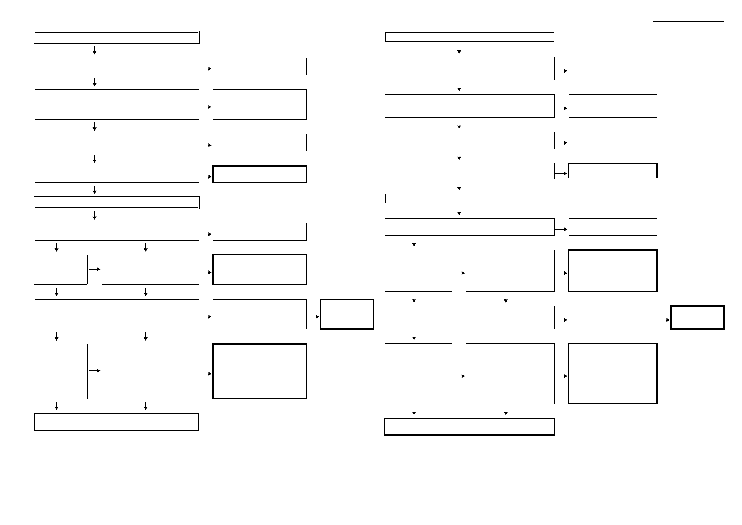
3. HDMI/DVI
3.1. No picture or sound is output
No picture or sound is output
YES
Check the HDMI/DVI cable connection
YES
Is the HDMI/DVI cable properly
connected?
YES
Are you using an HDMI/DVI selector,
repeater or a device for improving picture
quality?
NO
Are you using a certified HDMI cable (one
with the HDMI stamp)?
YES
Are you using an HDMI/DVI cable less
than 5 meters in length?
YES
Are the picture and sound output when
another HDMI/DVI cable is used?
NO
Checking the DVD player
YES
Is the DVD player's HDMI output setting
correct?
YES
When using a DENON DVD player, is the fluorescent display tube's
"HDMI" indicator lit?
If using a non-DENON DVD player, proceed to "YES".
YES
NO
Is sound output from the set's speaker terminals when the TV's power is
turned off or the connection cable between the TV and the set is
disconnected?
Are the picture and sound output when
the DVD player's resolution is changed?
NO
There may be a problem with the HDMI/
NO
DVI cable. Check the connection.
Disconnect everything and connect only
YES
the HDMI/DVI cable to check.
Use a certified HDMI cable (one with the
NO
HDMI stamp).
Replace the HDMI/DVI cable with one
NO
that is less than 5 meters in length (2
meters recommended) to check.
YES
The HDMI/DVI cable is defective.
Check the HDMI output setting, referring
YES
to the DVD player's operating
instructions.
Set the DVD player's output resolution
YES
to a resolution with which the TV is
compatible.
The DVD player may not be compatible
YES
with HDCP repeaters. Ask the DVD
player's manufacturer.
3. HDMI/DVI
3.1. 映像と音声が出力されない
映像と音声が出力されない
YES
HDMI/DVIケーブルの接続を確認する
YES
HDMI/DVI ケーブルは正しく接続され
ていますか?
YES
HDMI/DVI セレクター、リピーターや
画質改善装置を使用していますか?
NO
HDMI 認証品(HDMI 刻印がある)の
HDMI ケーブルを使用していますか?
YES
HDMI/DVI ケーブルは 5m 以下のもの
を使用していますか?
YES
別のHDMI/DVI ケーブルに交換すると
画像と音声が出力されますか?
NO
DVD プレーヤーを確認する
YES
DVD プレーヤーの HDMI 出力設定は
正しいですか?
YES
DENON の DVDプレーヤーを使用している場合、FL 管の "HDMI" インジ
ケータが点灯していますか?
他社の DVDプレーヤーを使用している場合は "YES" に進んでください。
YES
NO
TV の電源を切った時や TV と本機間の接続ケーブルをはずした時に、本機
のスピーカー端子から音声を出力しますか?
DVDプレーヤーの解像度を変えて画
像と音声が出力されますか?
NO
HDMI/DVI ケーブルは勘合がよくない
NO
ことがあります。接続を確認してくだ
さい。
YES
すべて取り外して HDMI/DVI ケーブル
のみを接続して確認してください。
NO
HDMI ケーブルは HDMI 認証品(HDMI
刻印がある)を使用してください。
HDMI/DVI ケーブルを 5m 以下 ( 推奨
NO
は2 m) に交換して確認してくださ
い。
YES
HDMI/DVI ケーブルが不良です。
DVD プレーヤーの取扱説明書を見て
NO
HDMI 出力を正しく設定してくださ
い。
DVDプレーヤーの出力解像度を、TV
YES
の対応可能な解像度に設定してくだ
さい。
DVDプレーヤーが HDCP リピーター
YES
に対応していない可能性があります。
DVDプレーヤーのメーカーに確認し
てください。
NO
Are the picture and sound output when a
different DVD player is used?
NO
YES
The DVD player is defective.
25
NO
別の DVDプレーヤーに交換すると画
像と音声が出力されますか?
NO
YES
DVDプレーヤーが不良です。
Page 26
AVR-1908 / AVR-788
Check the TV
Is the TV HDCP-compatible?
YES
Is the TV compatible with resolutions of 1080P?
YES
Is the TV's input set to HDMI?
YES
Are the picture and sound output when a different TV is used?
YES
Check the set (AVR-4308CI)
Use an HDCP-compatible TV. PC TVs
NO
cannot be used.
If the TV is not compatible with
resolutions of 1080P, no picture will be
NO
output, even if the DVD player's
resolution is set to 1080P.
Check the TV's input setting, referring to
NO
the TV's operating instructions.
NO
The TV is defective.
TV を確認する
TV は HDCP に対応していますか?
YES
TV は 1080P に対応していますか?
YES
TV の入力設定が HDMI 入力になっていますか?
YES
別の TV に交換すると画像と音声が出力されますか?
YES
本機を確認する
HDCP に対応している TV を使用して
NO
ください。PC 用の TV は使用できませ
ん。
TV が 1080P に対応していない場合、
NO
DVD プレーヤーを 1080P に設定して
も、画像は出力されません。
NO
TV の取扱説明書を見て入力設定を確
認してください。
NO
TV が不良です。
Is the set's input set to HDMI?
YES YES
Is the TV information
properly displayed on
the "Monitor info."
display menu?
YES YES
Does the set's wallpaper image appear on the TV when the HDMI/DVI
cable between the DVD player and the set is disconnected?
YES YES
When using a
DENON DVD player,
is the fluorescent
display tube's "HDMI"
indicator lit?
If using a nonDENON DVD player,
proceed to "NO".
YES YES
The HDMI output circuitry is defective.
(IC01 and surrounding circuitry)
The set does not recognize the TV.
NO
Is IC01 pin 76 "H" (3V-5V)? With the TV
connected, check the voltage of the IC on
the side on which the TV is connected.
The DVD player does not recognize the
connection with the set.
Is the HDMI connector (JACK01/JACK02/
NO
JACK03) pin 19 "H" (5V)? With the DVD
player connected, check the voltage of
the HDMI connector for the input on the
side on which the DVD player is
connected.
Check the set's input setting, referring to
NO
the set's operating instructions.
The pattern and circuit from the HDMI
NO
connector (JACK03) to the IC (IC01)
is defective.
Are the picture and sound output from
NO
other Monitor Out terminals (VIDEO out,
S-VIDEO out or Component out)?
The pattern and circuit from the HDMI
NO
connector (JACK01/JACK02/
JACK03) to the IC12 is defective.
NO
The HDMI output
circuitry is defective.
YES
(IC01 and surrounding
circuitry)
本機の入力設定が HDMI 入力になっていますか?
YES
本機が TV を認識していません
Monitorinfo. 表示メニュー
で TV の情報が正しく表示さ
れていますか?
YES YES
DVD プレーヤーと本機間の HDMI/DVI ケーブルを取り外した時、TV に本
機の壁紙の画像が表示されますか?
YES
DENON の DVD プレーヤー
を使用している場合、FL 管
の"HDMI"インジケータが点
灯していますか?
他社の DVD プレーヤーを使
用している場合は "NO" に進
んでください。
YES YES
HDMI 入力系の回路が不良です。
(IC01 周辺回路 )
IC01 の 76pin が "H"(3V-5V) となって
NO
いますか?
TV を接続している状態で、TV を接続
している側の IC の電圧を確認してく
ださい。
DVD プレーヤーが本機との接続を認
識していません
HDMIコネクター (JACK01/JACK02/
JACK03) の 19pin が "H"(5V) となって
NO
いますか?
DVD プレーヤーを接続している状態
で、DVD プレーヤーを接続している
入力の HDMIコネクターの電圧を確
認してください。
NO
本機の取扱説明書を見て入力設定を
確認してください。
HDMI コネクター(JACK03) から
NO
IC(IC01)までのパターンおよび回路が
不良です。
他の MonitorOut(VIDEOout/S-VIDEO
NO
out/Componentout) からは出力され
ますか?
HDMI コネクター (JACK01/JACK02/
NO
JACK03) から IC12 までのパターンお
よび回路が不良です。
NO
HDMI出力系の回路が
YES
不良です。
(IC01 周辺回路 )
26
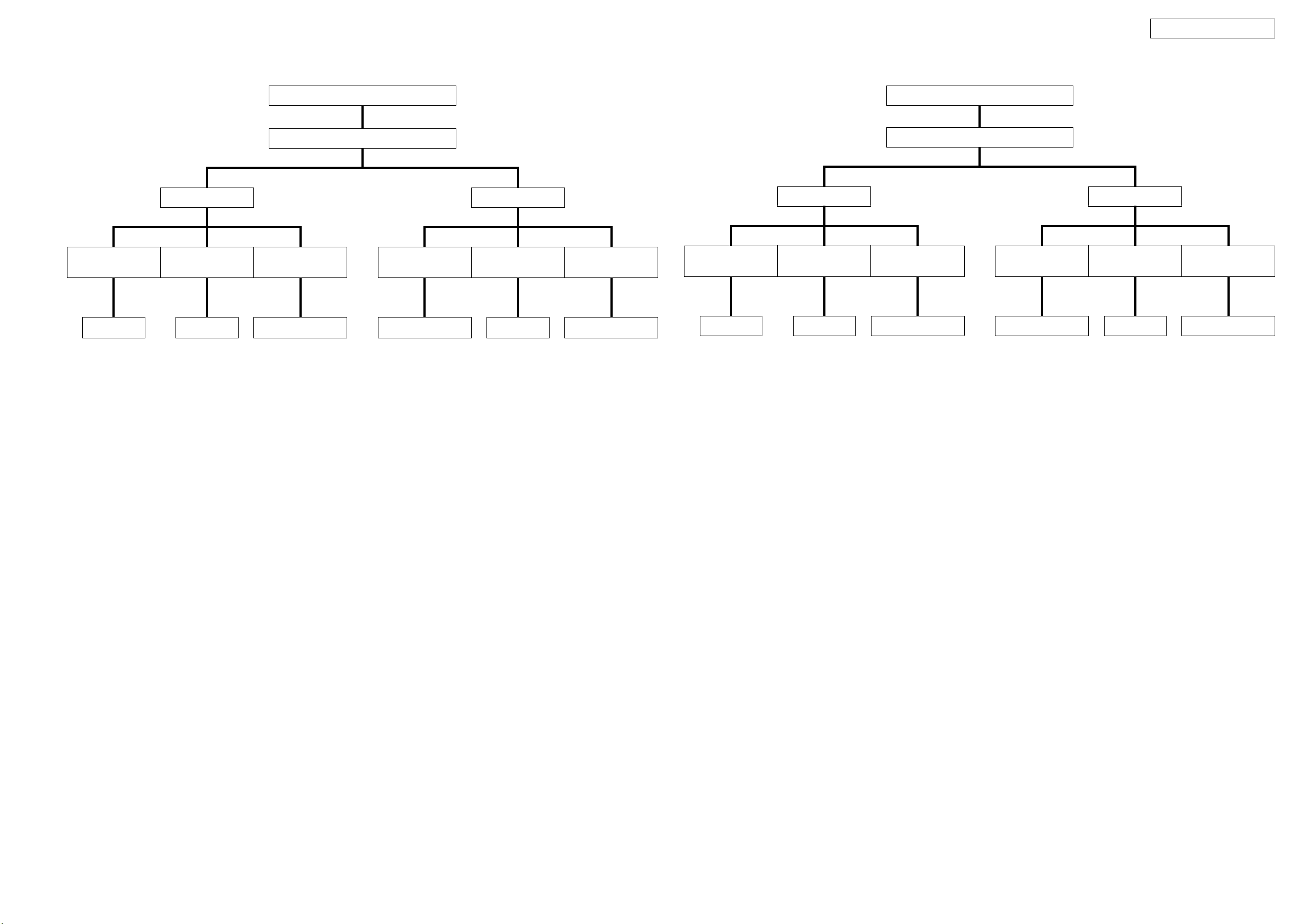
Page 27
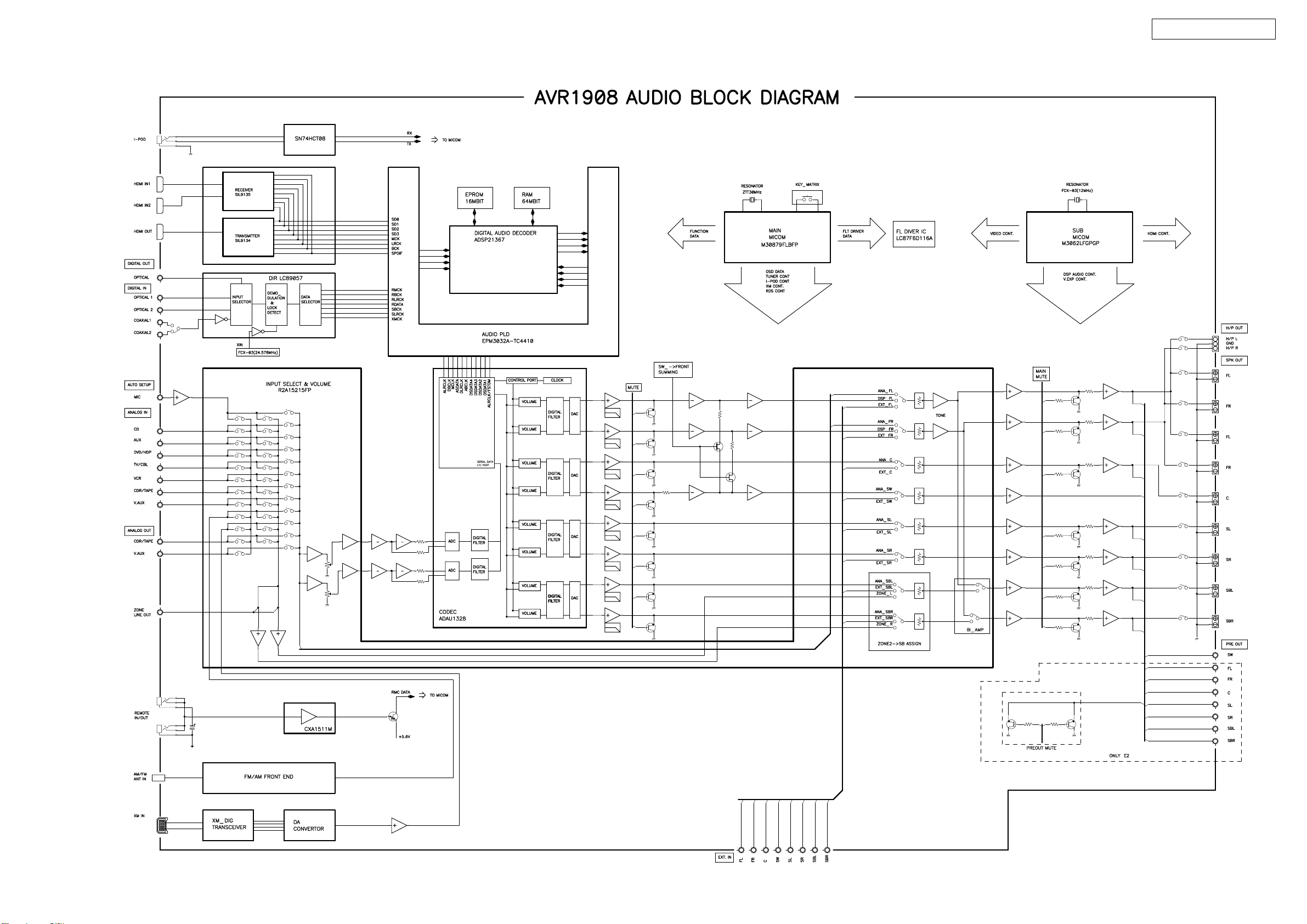
BLOCK DIAGRAM
AUDIO BLOCK DIAGRAM
AVR-1908 / AVR-788
27
Page 28
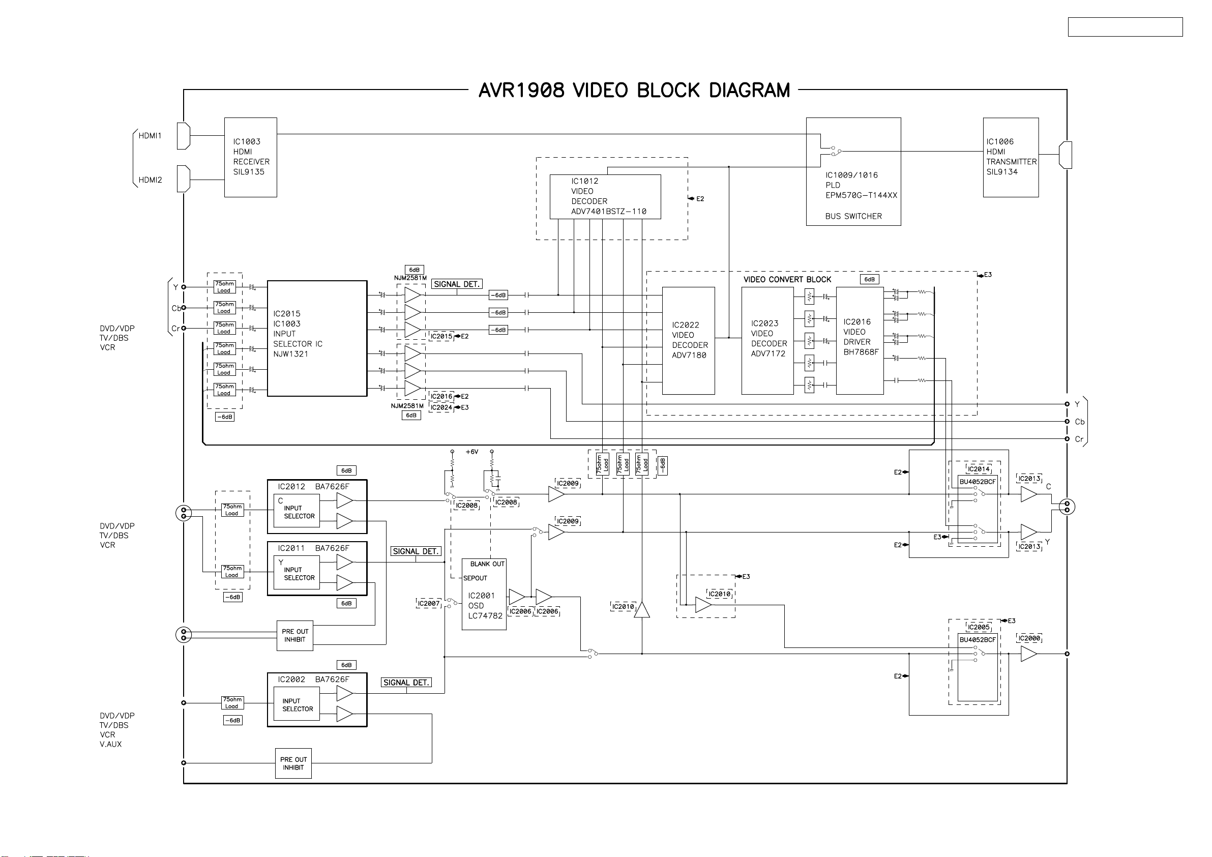
VIDEO BLOCK DIAGRAM
AVR-1908 / AVR-788
HDMI IN
COMPONENT IN
HDMI OUT
COMPONENT
OUT
S(Y/C) IN
S(Y/C) REC OUT
CVBS IN
CVBS REC OUT
S(Y/C) OUT
CVBS OUT
28
Page 29
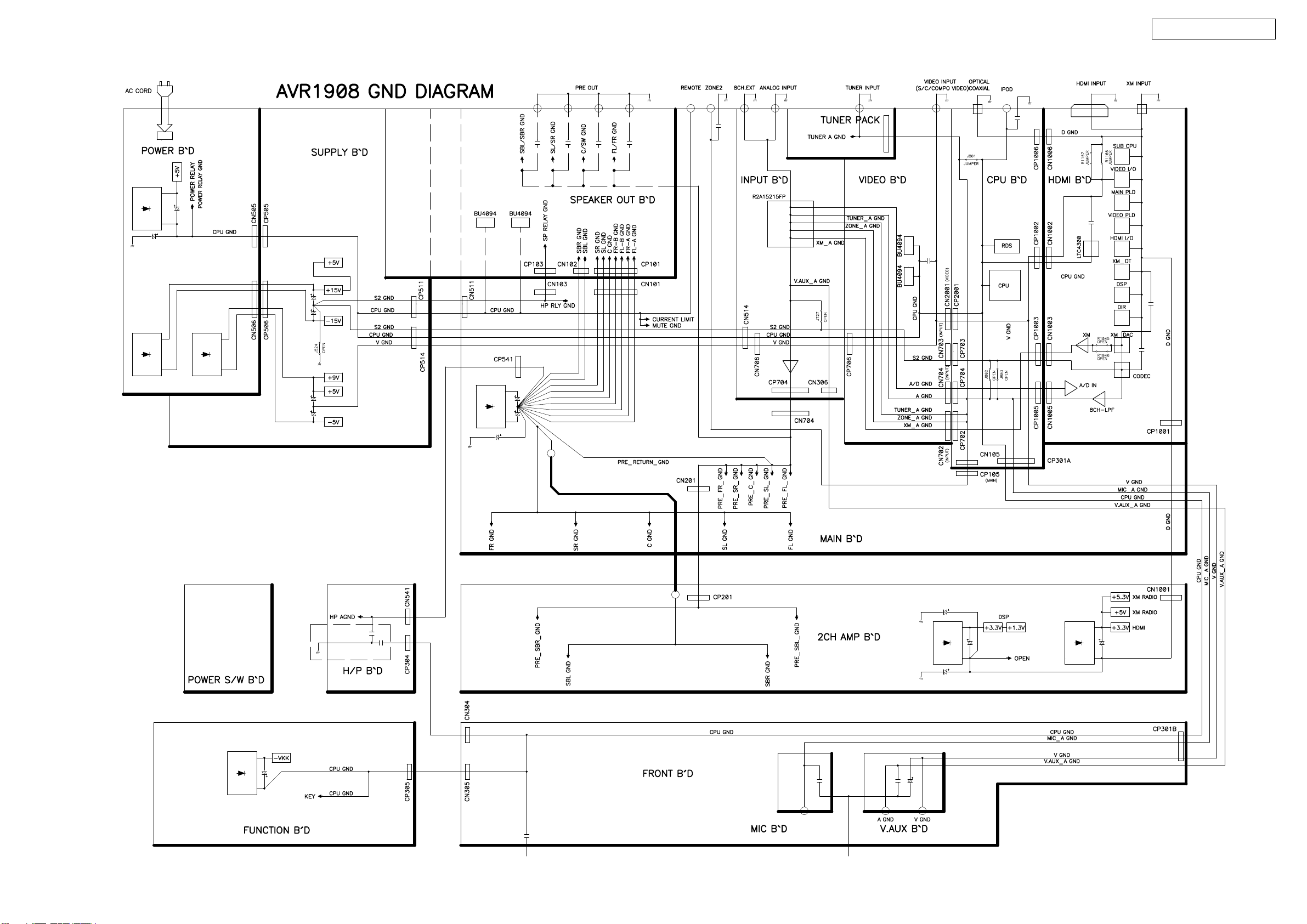
GND DIAGRAM
AVR-1908 / AVR-788
29
Page 30
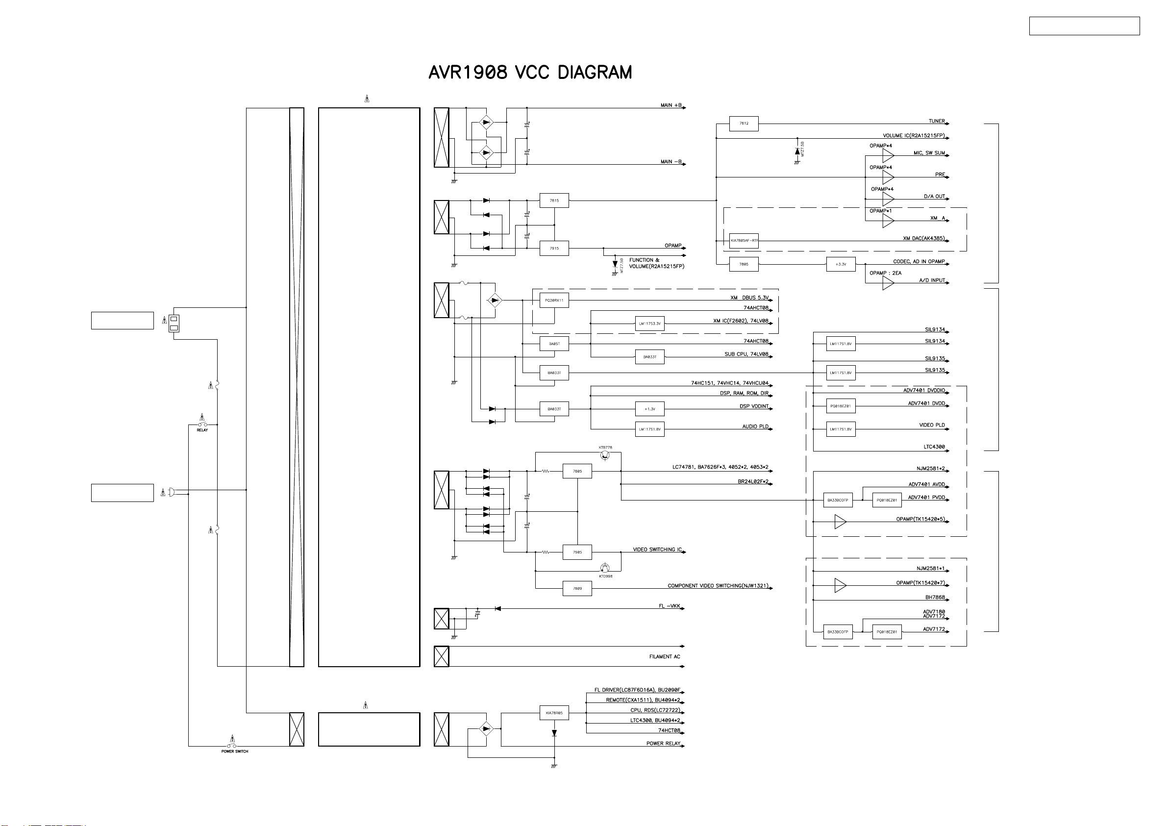
VCC DIAGRAM
AC OUTLET
AVR-1908 / AVR-788
S1(AMP +B )
S2 TOTAL : 358m A
S2(+15V,-15V)
E3
S3(DSP.XM.HDMI)
E3
AC CORD
S3 TOTAL : 1475m A
MAIN TRANS
E2
S4(VIDEO)
S4 TOTAL : 959m A
E3
S5(FL -VKK)
S6(FILAMENT)
SUB TRANS
30
Page 31

LEVEL DIAGRAMS (1/2)
7CH LEVEL DIAGRAM
AVR-1908 / AVR-788
31
Page 32

LEVEL DIAGRAMS (2/2)
SUB WOOFER LEVEL DIAGRAM
AVR-1908 / AVR-788
32
Page 33

SEMICONDUCTORS
Only major semiconductors are shown, general semiconductors etc. are omitted to list.
主な半導体を記載しています。汎用の半導体は記載を省略しています。
1. IC’s
M30879FLBFP (IC830)
)
/D5/D4)
/D3/D2)
2/A2(/D2/D1)
)
7/A7(/D7/D6)
/-/D7
/AN2_6/A6(/D6/D5)
P2_7/AN2_
P2_5/AN2_5/A5(
P2_4/AN2_4/A4(/D4/D3)
P2_2/AN2_
P2_3/AN2_3/A3(
P2_6
VSS
VCC2
P3_0/A8(
M30879FLBFP
/A9
1
_
3
P
0
/A1
2
P3_
4
5
2
3
/A1
/A1
/A1
/A1
6
4
5
_
3
P
P3_3/A11
P3_7
P3_
P3_
P0_7/AN0_7/D7
P0_6/AN0_6/D6
P0_5/AN0_5/D5
P0_4/AN0_4/D4
P0_3/AN0_3/D3
P0_2/AN0_2/D2
P0_1/AN0_1/D1
P0_0/AN0_0/D0
P10_7/AN7/KI3
P10_6/AN6/KI2
P10_5/AN5/KI1
P10_4/AN4/KI0
P10_3/AN3
P10_2/AN2
P10_1/AN1
AVSS
P10_0/AN0
VREF
P9_7/ADTRG/SIN4
AVCC
/D1/D0)
/D12
P2_0/AN2_0/A0(/D0/-
P1_7/D15/INT5
P1_0/D8
P1_1/D9
81
82
83
84
85
86
87
88
89
90
91
92
93
94
95
96
97
98
99
00
1
1 2 3 4 5 6 7 8 9 101112131415161718192021222324252627282930
P1_2/D10
P1_3/D11
P1_4
P1_5/D13/INT3
P1_6/D14/INT4
P2_1/AN2_1/A1(
/A16
P4_0
/A17
P4_1
P4_2/A18
P4_3/A19
515253545556575859606162636465666768697071727374757677787980
AVR-1908 / AVR-788
50
49
48
47
46
45
44
43
42
41
40
39
38
37
36
35
34
33
32
31
P4_4/CS0
P4_5/CS1
P4_6/CS2
P4_7/CS3
P5_0/WRL/WR
P5_1/WRH/BHE
P5_2/RD
P5_3/BCLK
P5_4/HLDA
P5_5/HOLD
P5_6/ALE
P5_7/RDY/CLKOUT
P6_0/CTS0/RTS0
P6_1/CLK0
P6_2/RXD0/SCL0
P6_3/TXD0/SDA0
P6_4/CTS1/RTS1/CTS0/CLKS1
P6_5/CLK1
P6_6/RXD1/SCL1
P6_7/TXD1/SDA1
/U
P9_4/DA1/TB4IN
P9_3/DA0/TB3IN
P9_5/ANEX0/CLK4
P9_6/ANEX1/SOUT4
P9_2/TB2IN/SOUT3
K3
BYTE
/XCIN
CNVSS
P8_7
P8_6/XCOUT
P9_1/TB1IN/SIN3
P9_0/TB0IN/CL
XOUT
RESET
VSS
XIN
VCC1
P8_5/NMI
P8_4/INT2/ZP
/INT0
P8_3/INT1
P8_2
P8_1/TA4IN/U
IN
/TA3
P7_7
P8_0/TA4OUT
UT
O
/TA3
P7_6
IN/W
/TA2
P7_5
OUT/W
/TA1IN/V
/TA2
P7_4
P7_3/CTS2/RTS2
(1)
(1)
N
I
/TA1OUT/V
/TA0OUT
A2
/CLK2
/SD
P7_2
P7_0/TXD2
P7_1/RXD2/SCL2/TA0IN/TB5
NOTES:
1. P7_0 and P7_1 are N channel open-drain output pins.
M30879FLBFP Terminal Function
PIN NO. PIN NAME I/O FUNCTION
1 P96/SOUT4 SW_SUM O Bass Management Control
2 P95/CLK4 iPod DET I iPod Dock Det
3 P94/TB4 2090_CLK/SEL2 O AVR1708 : EXPANDER Control Pin / AVR1508 : VIDEO Control Pin
4 P93/TB3 2090_DATA/SEL1 O AVR1708 : EXPANDER Control Pin / AVR1508 : VIDEO Control Pin
5 P92/SOUT3 SHARC_SDOUT O DSP(IC801 : ADSP-21367)Control Pin
6 P91/SIN3 SHARC_SDIN I DSP(IC801 : ADSP-21367)Control Pin
7 P90/CLK3 SHARC _SCLK O DSP(IC801 : ADSP-21367)Control Pin
8 BYTE BYTE - GND
9 CNVCS CNVSS I UPGRADE PIN
10 P87 1328 CE O CODEC(IC808 : ADAU1328) Control Pin
11 P86 XM DACMS O XM DAC(IC06 : AK4385)Control Pin
12 RESET RESET I RESET (Det = "L")
13 XOUT X2 O Clock(12MHz )
33
Page 34

AVR-1908 / AVR-788
PIN NO. PIN NAME I/O FUNCTION
14 VSS VSS - GND
15 XIN X1 I Clock(12MHz)
16 VCC VCC - +5V
17 P85/NMI NMI I -
18 P84/INT2 FLAG0 I DSP(IC801 : ADSP-21367) Control Pin
19 P83/INT1 POWER DOWN I Power Down Detection Pin (Det = "L")
20 P82/INT0 PROTECTION I Protect Detection (Det = "L")
21 P81 XM DAC_CLK(MC) O XM DAC(IC06 : AK4385)Control Pin
22 P80 XM DAC_DATA(MDI) O XM DAC(IC06 : AK4385)Control Pin
23 P77 FLD_RESET O FL DRIVER Control Pin
24 P76 FLD_CE O FL DRIVER Control Pin
25 P75 FLD_CLK O FL DRIVER Control Pin
26 P74 FLD_DATA O FL DRIVER Control Pin
27 P73/CTS2 2090-C_CLK O IC301 : BU2090(EXPANDER)Control Pin
28 P72/CLK2 2090-C_DATA O IC301 : BU2090(EXPANDER)Control Pin
29 P71/RXD2 RXD MIXMO I XM Radio Control Pin
30 P70/TXD2 TXD MOXMI O XM Radio Control Pin
31 P67/TXD1 TXD MO232I O Flash Starter/DENON Writer Control Pin
32 P66/RXD1 RXD MI232O I Flash Starter/DENON Writer Control Pin
33 P65/CLK1 LIMIT DET I Current Limit Detection
34 P64/CTS1 LIMIT O Current Limit Control Pin
35 P63/TXD0 TXD_iPod O iPod Dock Control Pin
36 P62/RXD0 RXD_iPod I iPod Dock Control Pin
37 P61/CLK0 XM ANT REV I XM Radio Control Pin
38 P60/CTS0 XM LINK ACTIVE I XM Radio Control Pin
39 P57 TUNED I FM/AM TUNED Detection(Det = "L")
40 P56 STEREO I FM STEREO Detection(Det = "L")
41 P55/EPM FLASH EPM I UPGRADE PIN
42 P54 VOL UP I MASTER VOLUME KNOB(Rotary Encoder) Rotational Detection
43 P53 VOL DOWN I MASTER VOLUME KNOB(Rotary Encoder) Rotational Detection
44 P52 SEL UP I SELECTOR KNOB(Rotary Encoder) Rotational Detection
45 P51 SEL DOWN I SELECTOR KNOB(Rotary Encoder) Rotational Detection
46 P50/CE FLASH CE I UPGRADE PIN
47 P47 PLL/RDS DIN O TUNER PLL(LC72131)/RDS(LC72720)Control Pin
48 P46 PLL/RDS CLK O TUNER PLL(LC72131)/RDS(LC72720) Control Pin
49 P45 PLL STB O TUNER PLL(LC72131)Control Pin
50 P44 PLL_DOUT I TUNER PLL(LC72131)Control Pin
51 P43 RDS RESET O RDS(IC805 : LC72720)Control Pin
52 P42 RDS CE O RDS(IC805 : LC72720)Control Pin
53 P41 RDS DOUT I RDS(IC805 : LC72720)Control Pin
54 P40 89057 INT I DIR(IC807 : LC89057) Control Pin
55 P37 89057 RESET O DIR(IC807 : LC89057) Control Pin
56 P36 89057 CE O DIR(IC807 : LC89057) Control Pin
57 P35 89057 SDIN I DIR(IC807 : LC89057) Control Pin
58 P34 89057 EMPHA I DIR(IC807 : LC89057) Control Pin
59 P33
60 P32 SHARC_CE O DSP(IC801 : ADSP-21367) Control Pin
61 P31 V-CODEC_SDA O VIDEO CODEC (IC1019 : ADV7172&IC1018 : ADV7180) Control Pin
62 VCC VCC - +5V
63 P30 V-CODEC_SCL O VIDEO CODEC (IC1019 : ADV7172&IC1018 : ADV7180) Control Pin
64 VSS VSS - GND
65 P27 SHARC_RESET O DSP(IC801 : ADSP-21367) Control Pin
66 P26 EEPROM RESET O Flash Memory(IC803 : MBM29LV160BE90TN) Control Pin
67 P25 DSP POWER O DSP POWER ON/OFF
68 P24 HPD0 O HDMI_IN1 HPD Control Pin
V-CODEC RESET/VMUTE
O VIDEO CODEC (IC1019 : ADV7172&IC1018 : ADV7180) Control Pin
34
Page 35

AVR-1908 / AVR-788
PIN NO. PIN NAME I/O FUNCTION
69 P23 HPD1 O HDMI_IN2 HPD Control Pin
70 P22 H/P DET I HP Jack Insert Detection(Det ="H")
71 P21 FUNCTION UP I FUNCTION SELECTOR KNOB(Rotary Encoder)Rotational Detection
72 P20 FUNCTION DOWN I FUNCTION SELECTOR KNOB(Rotary Encoder)Rotational Detection
73 P17/INT5 RMC I Remote Control Unit Signal Reception
74 P16/INT4 MIC IN I MIC Insert Detection(Det ="H")
75 P15/INT3 POWER Key I POWER KEY Detection
76 P14/D12 POWER RELAY O MAIN TRANS RELAY Control Pin
77 P13/D11 RED LED O POWER/STANDBY LED Control Pin
78 P12/D10 VOL DATA O FUNCTION/VOLUME(IC700 : R2A15215) Control Pin
79 P11/D9 VOL CLK O FUNCTION/VOLUME(IC700 : R2A15215) Control Pin
80 P10/D8
81 P07/D7 4094(MUTE)_STB O IC111 : BU4094(EXPANDER) Control Pin
82 P06/D6 4094(RLY)_STB O IC110 : BU4094(EXPANDER) Control Pin
83 P05/D5 4094(XM)_STB O IC12 : BU4094(EXPANDER) Control Pin
84 P04/D4 89057/1328 SCLK O DIR(IC807 : LC89057)&CODEC(IC808 : ADAU1328) Control Pin
85 P03/D3 89057/1328 SDOUT O DIR(IC807 : LC89057)&CODEC(IC808 : ADAU1328) Control Pin
86 P02/D2 COMP DET I COMPONENTSignal Detection (AVR1708/688 Only)
87 P01/D1 CVBS DET I CONPOSIT Signal Detection (AVR1708/688 Only)
88 P00/D0 S-VIDEO DET I S VIDEO Signal Detection (AVR1708/688 Only)
89 P107/AN7 4094_OE O IC12&110&111 : BU4094(EXPANDER) Control Pin
90 P106/AN6 KEY1 I Key-1 Detection(A/D)
91 P105/AN5 KEY2 I Key-2 Detection(A/D)
92 P104/AN4 KEY3 I Key-3 Detection(A/D)
93 P103/AN3 1328 RESET O CODEC(IC808 : ADAU1328) Control Pin
94 P102/AN2 SET OPTION I Area Setup
95 P101 4094_CLK O IC12&110&111 : BU4094(EXPANDER) Control Pin
96 AVSS AVSS - GND
97 P100 4094_DATA O IC12&110&111 : BU4094(EXPANDER) Control Pin
98 VREF VREF - AD Reference Level(+5V)
99 AVCC AVCC - AD +5V
100 P97/SIN4 INH O Identifying Signal Control (AVR1530 Only)
1328 SDIN/MIC
OVERLOAD
I CODEC(IC808 : ADAU1328) Control Pin
35
Page 36

R2A15215FP (IC700)
80
AVR-1908 / AVR-788
51
81
100
MUTE
AVEE
N.C.
ADCL
ADCR
AGND
N.C.
INR1
INL1
INR2
INL2
INR3
INL3
INR4
INL4
INR5
INL5
INR6
INL6
INR7
INL7
INR8
INL8
N.C.
INRA/RECR1
INLA/RECL1
N.C.
INR9
INL9
N.C.
50
31
1
SUBR
DGND
DATA
CLOCK
50 49 48 47 46 45 44 43 42 41 40 39 38 37 36 35 34 33 32 31
51
52
53
54
55
MCU
I/F
AVEE
0/-6/-12/-18dB
ATT
56
MAI N
57
58
SUB
MAI N
59
60
61
SUB
62
63
64
65
66
67
68
69
70
71
72
73
74
75
76
REC
77
78
79
80
SUBL
MAI N
SUB
SBLCIN
SBRCIN
FRIN2
0~-95dB,
(0.5dBstep)
0~-95dB,
(0.5dBstep)
30
FLIN2
-
-
SRIN2
Bass/ Treb
-14~+14dB
(2dB step)
Bass/ Treble
-14~+14dB
(2dB step)
SLIN2
Tone
Tone
SWIN2
le
CIN2
Tone+MIX
Tone+MIX
Bypass
SBLIN2
SBRIN2
Bypass
Tone
Tone
+42~-95dB,
- (0.5dBstep)
+42~-95dB,
- (0.5dBstep)
+42~-95dB,
- (0.5dBstep)
+42~-95dB,
- (0.5dBstep)
+42~-95dB,
- (0.5dBstep)
+42~-95dB,
- (0.5dBstep)
N.C.
TRER
BASSR2
+42~0dB
(0.5dBstep)
+42~0dB
(0.5dBstep)
CMIX
SWMIX
BASSR1
AVCC
N.C.
30
AVCC
N.C.
29
28
TREL
27
BASSL2
BASSL1
26
N.C.
25
FRC
24
FROUT
23
22
AGND
FLOUT
21
20
FLC
AGND
19
CC
18
COUT
17
AGND
16
SWOUT
15
SWC
14
13
N.C.
SRC
12
SROUT
11
AGND
10
SLOUT
9
SLC
8
AGND
7
SBRC
6
SBR OUT
5
AGND
4
SBL OUT
3
SBLC
2
N.C.
1
81 82 83 84 85 86 87 88 89 90 91 92 93 94 95 96 97 98 99
RECL3
N.C.
FLIN1
CIN1
FRIN1
SWIN1
SLIN1
SRIN1
INRB/RECR2
INLB/RECL2
INR10/RECR4
INL10/RECL4
INR11/RECR5
N.C.
INL11/RECL5
N.C.
N.C.
RECR3
36
100
SBLIN1
SBRIN1
Page 37

R2A15215FP Terminal Function
AVR-1908 / AVR-788
PIN No.
23,21,
17,15,
11,9,
5,3
24,20,
18,14,
12,8,
6,2
4,7,10,16,
19,22,56
28,34
26,27,
32,33
30
43,42,
41,40,
39,38,
37,36
93,94,
95,96,
97,98,
99,100
Name
FROUT,FLO UT,
COUT,SWOUT,
SROUT, SLO UT,
SBROUT,S BL OUT
FRC,FLC,
CC,SWC,
SRC,SLC,
SBRC,SBL C
AGN D
TREL, TRE R
BA SSL1,BA SSL2
BA SSR1,BASSR2
AVCC
FRIN2, FLIN2,
SRN2,SLIN2,
SWIN2,CIN2 ,
SBRIN2,S BLIN2
FLIN1, F RIN1,
CIN1,SWIN1 ,
SLIN1,S RIN1,
SBLIN1,S BRI N1
Function
Output pin of FL/ FR/C/SW/SL/ SR/SBL/ SBR channel
Connects capacitor fo r reducing click no ise of
L/R /C/SW/SL/SR/SBL/ SBR channel vol ume
Analog groun d of intern al circuit
Frequency characteristic setting pin of L/R chann el tone control (Treble)
Frequency characteristic setting pin of L/R chann el tone control (Bass)
Positive powe r supply to int ernal cir cuit
Input pin of L/R /C/SW/ SL/ SR/SBL /SBR channel (Multi IN 1/2)
48 DGN D
49 DATA
Digital ground of intern al circuit
Input pin of c ontrol data
50 CLOCK Input pin of c ontrol clock
52
59,61,63,
65,67,69,
71,73,79
58,60,62,
64,66,68,
70,72,78
51
AVEE
INL1, INL2, I N L3,
INL4, INL5, INL6,
INL7, INL8, INL9
INR1,INR2, I N R3,
INR4,INR5,I NR6,
INR7,INR8,I NR9
MUTE
44,45 SBRCIN,SBL CIN
46,47 SUBL,SU BR
54,55 ADCL, ADCR
90,91
75,76,
81,82,
83,84,
85,86
1,13,25,29,31,
35,53,
57,74,77,80,
87,88,89,92
RECR3,RECL3
INRA/RECR1,INLA/RECL1,
INRB/REC R2,INLB/ RECL2,
INR10/RECR4,I NL10/RECL4,
INR11/RECR5,I NL11/RECL5
N.C.
Negative pow er supply to internal cir cuit
Input pin of L/R channel ( I nput Selector)
Outside Mute Con trol PIN
Input pin for S BL/ SBR channel Volum e
Output pin for L/R chann el SUB Outpu t
Output pin for L/R chann el ADC
Output pin for L/R chann el REC Output
Input pin of L/R channel ( I nput Selector)/
Output pin for L/R chann el REC Output
No Connected PIN
37
Page 38

ADSP21367KSZ (IC1029)
208 157
1
PIN 1 INDICATOR
TOP VIEW
(PINS DOW N)
AVR-1908 / AVR-788
156
52
105
10453
ADSP21367KSZ Terminal Function
Pin No. Signal Pin No. Signal Pin No. Signal Pin No. Signal
1 VDD 53 VDD 105 VDD 157 VDD
2 DATA28 54 GND 106 GND 158 VDD
3 DATA27 55 IOVDD 107 IOVDD 159 GND
4 GND 56 ADDR0 108 SDCAS
5 IOVDD 57 ADDR2 109 SDRAS
6 DATA26 58 ADDR1 110 SDCKE 162 VDD
7 DATA25 59 ADDR4 111 SDWE
8 DATA24 60 ADDR3 112 WR
9 DATA23 61 ADDR5 113 SDA10 165 TCK
10 GND 62 GND 114 GND 166 GND
11 VDD 63 VDD 115 IOVDD 167 VDD
12 DATA22 64 GND 116 SDCLK0 168 TMS
13 DATA21 65 IOVDD 117 GND 1 69 CLK_CFG0
14 DATA20 66 ADDR6 118 VDD 170 BOOTCFG0
15 IOVDD 67 ADDR7 119 RD
16 GND 68 ADDR8 120 ACK 172 EMU
17 DATA19 69 ADDR9 121 FLAG3 173 BOOTCFG1
18 DATA18 70 ADDR10 122 FLAG2 174 TDO
19 VDD 71 GND 123 FLAG1 175 DAI4
20 GND 72 VDD 124 FLAG0 176 DAI2
21 DATA17 73 GND 125 DAI20 177 DAI3
22 VDD 74 IOVDD 126 GND 178 DAI1
23 GND 7 5 ADDR11 127 VDD 179 IOVD D
24 VDD 76 ADDR12 128 GND 180 GND
25 GND 7 7 ADDR13 129 IOVDD 181 VDD
26 DATA16 78 GND 130 DAI19 182 GND
27 DATA15 79 VDD 131 DAI18 183 DPI14
28 DATA14 80 AVSS 132 DAI17 184 DPI13
29 DATA13 81 AVDD 133 DAI16 185 DPI12
30 DATA12 8 2 GND 134 DAI15 186 DPI11
31 IOVDD 83 CLKIN 135 DAI14 187 DPI10
32 GND 8 4 XTAL2 136 DAI13 188 DPI9
33 VDD 85 IOVDD 137 DAI12 189 DPI8
34 GND 86 GND 138 VDD 190 DPI7
35 DATA11 87 VDD 139 IOVDD 191 IOVDD
36 DATA10 88 ADDR14 140 GND 192 GND
37 DATA9 89 GND 141 VDD 193 VDD
38 DATA8 90 IOVDD 142 GND 194 GND
39 DATA7 91 ADDR15 143 DAI11 195 DPI6
40 DATA6 92 ADDR16 144 DAI10 196 DPI5
41 IOVDD 93 ADDR17 145 DAI8 197 DPI4
42 GND 94 ADDR18 146 DAI9 198 DPI3
43 VDD 95 GND 147 DAI6 199 DPI1
44 DATA4 96 IOVDD 148 DAI7 200 DPI2
45 DATA5 97 ADDR19 149 DAI5 201 CLK OUT
46 DATA2 98 ADDR20 150 IOVDD 202 RESET
47 DATA3 99 ADDR21 151 GND 203 IOVDD
48 DATA0 100 ADDR23 152 VDD 204 GND
49 DATA1 101 ADDR22 153 GND 205 DATA30
50 IOVDD 102 MS1
51 GND 103 MS0
52 VDD 104 VDD 156 VDD 208 VDD
154 VDD 206 DATA31
155 GND 207 DATA29
160 VDD
161 VDD
163 TDI
164 TRST
171 CL K_CFG1
38
Page 39

LC89057W (IC1032)
AVR-1908 / AVR-788
RXOUT
RX0
RX1
RX2
RX3
RX4
RX5/VI
RX6/UI
LPF
TMCK/PIO0
TBCK/PIO1
TLRCK/PIO2
TDATA/PIO3
TXO/PIOEN
1
2
3
4
5
8
9
10
13
44
45
46
47
48
EMPHA/UO33AUDIO/VO35INT40CL39CE38DI
32
Clock
Selector
27
Microcontroller
Input
Selector
Modulation
or
Parallel Port
29
XIN
C bit, U bit
Demodulation
&
Lock Detect
PLL
28
XOUT
XMCK34CKST
I/F
Data
Selector
I/N
XMODE
41
37
36
21
24
16
17
20
22
23
DO
RERR
RD ATA
SDIN
RMCK
RBCK
RLRCK
SBCK
SLRCK
36 RERR1RXOUT
35 INT2RX0
34 CKST3RX1
TOP VIEW
33 AUDIO/VO4RX2
32 EMPHA/UO5RX3
31 DGND6DGND
30 DVDD7DVDD
29 XIN8RX4
28 XOUT9RX5/VI
27 XMCK10RX6/UI
26 DVDD11DVDD
25 DGND12DGND
24 SDIN37DO
23 SLRCK38DI
22 SBCK39CE
21 RDATA40CL
20 RLRCK41XMODE
19 DVDD42DGND
18 DGND43DVDD
17 RBCK44TMCK/PIO0
16 RMCK45TBCK/PIO1
15 AGND46TLRCK/PIO2
14 AVDD47TDATA/PIO3
13 LPF48TXO/PIOEN
LC89057W Terminal Function
Pin
No.
1 RXOUT O Input bi-phase select data output terminal
2 RX0 I TTL compatible digital data input terminal
3 RX1 I Coaxial compatible amp built-in digital data input terminal
4 RX2 I TTL compatible digital data input terminal
5 RX3 I TTL compatible digital data input terminal
6 DGND — Digital GND
7 DVDD — Digital power
8 RX4 I TTL compatible digital data input terminal
9 RX5/VI I TTL compatible digital data/Validity flag input terminal for modulation
10 RX6/UI I TTL compatible digital data/User data input terminal for modulation
11 DVDD — Digital power for PLL
12 DGND — Digital GND for PLL
13 LPF O PLL loop filter connecting terminal
14 AVDD — Analog power for PLL
15 AGND — Analog GND for PLL
16 RMCK O RMCK clock output terminal (256fs, 512fs, XIN, VCO)
17 RBCK O/I RBCK clock in/output terminal (64fs)
18 DGND — Digital GND
19 DVDD — Digital power
20 RLRCK O/I RLRCK clock in/output terminal (fs)
21 RDATA O Serial audio data output terminal
22 SBCK O SBCK clock output terminal (32fs, 64fs, 128fs)
23 SLRCK O SLRCK clock output terminal (fs/2, fs, 2fs)
24 SDIN I Serial audio data input terminal
25 DGND — Digital GND
26 DVDD — Digital power
27 XMCK O Osc. amp output terminal
Pin Name
I/O
Function
39
Page 40

AVR-1908 / AVR-788
Pin
No.
Pin Name I/O
Function
28 XOUT O X’tal osc. connecting output terminal
29 XIN I X’tal osc. connection, external clock input terminal (24.576MHz or 12.288MHz)
30 DVDD — Digital power
31 DGND — Digital GND
32 EMPHA/UO I/O Emphasis information/U-data output/Chip address setting terminal
33 AUDIO/VO I/O Non-PCM detect/V-flag output/ Chip address setting terminal
34 CKST I/O Clock switch transition period output/Demodulation master or slave function switching terminal
35 INT I/O Interrupt output for µcom (Interrupt factor selectable)/Modulation or general I/O switching terminal
36 RERR O PLL lock error, data error flag output
37 DO O µcom I/F, read out data output terminal (3-state)
38 DI I µcom I/F, write data input terminal
39 CE I µcom I/F, chip enable input terminal
40 CL I µcom I/F, clock input terminal
41 XMODE I System reset input terminal
42 DGND — Digital GND
43 DVDD — Digital power
44 TMCK/PIO0 I/O 256fs system clock input for modulation/General I/O in/output terminal
45 TBCK/PIO1 I/O 64fs bit clock input for modulation/General I/O in/output terminal
46 TLRCK/PIO2 I/O fs clock input for modulation/General I/O in/output terminal
47 TDATA/PIO3 I/O Serial audio data input for modulation/General I/O in/output terminal
48 TXO/PIOEN O/I Modulation data output/ General I/O enable input terminal
* For latch-up countermeasure, perform each power supply ON/OFF in the same timing.
BU2090F (IC301)
1
VSS
DATA
CLOCK
LCK
Q0
Q1
Q2
Q4
2
3
4
5
6
7
8
9
CONTROL CIRCUIT
12-bit SHI FT REGISTER
12- bit STRAGE REGISTER
OUTPUT BUF FER ( OPEN DRAI N)
17
14
13
18
16
15
12
11Q3
10
VDD
OE
Q11
Q10
Q9
Q8
Q7
Q6
Q5
40
Page 41

LC87F6D16A (IC302)
AVR-1908 / AVR-788
61
80
4160
40
21
1
20
LC87FD16A Terminal Function
41
Page 42

ADAU1328 (IC1031)
AVR-1908 / AVR-788
42
Page 43

BA7626 (IC2002,2011,2012)
AVR-1908 / AVR-788
ABE
Monitor OUT
MONITOR OUT
1
2
GND
IN5
3
GND
4
5
IN4
CTL E
6
IN3
7
CTL D
8
C D E V OUT 1 C D E V OUT 2
LL* IN 1 LL*
H L * IN 2 H L * IN 2 H L *
L H * IN 3 L H * IN 3 L H * IN 3
H H L IN 4 H H L IN 4 H H L IN 4
HHH IN 5 HHH IN 5 HHH IN 5
Note 1: * mark means that feasible for either H or L.
Note 2: Each input terminal is provided with sink chip clamp (BA7625).
Each input terminal takes 20kohm at the end (BA7626).
BA4510F (IC1035,1036)
LOGIC
6dB
LOGIC
6dB
⎯
16
15
14
13
12
11
10
9
IN1
CTL A
V OUT1
Vcc
IN2
CTL B
V OUT2
CTL C
LL* IN 1
⎯
OUT1
Ð IN1
+ IN1
1
2
1ch
+
Ð
3
EE
V
4
2ch
+
Ð
VCC
8
OUT2
7
Ð IN2
6
+ IN2
5
BU4094BCF (IC110,111,2003,2004)
STROBE
SERIAL
IN
CLOCK
1
2
3
4
1
Q
5
Q2
6
Q3
7
Q4
8
SS
V
16
15
14
13
12
11
10
9
V
DD
OUTPUT
ENABLE
Q5
Q6
Q7
Q8
Q'S
QS
43
Page 44

MBM29LV160BE90TN (IC1028)
SN74LV573APWR (IC806)
1
OE
2
D0
3
D1
4
D2
D3
5
6
D4
7
D5
8
D6
9
D7
GND
10
AVR-1908 / AVR-788
Vcc
20
Q0
19
Q1
18
Q2
17
Q3
16
Q4
15
Q5
14
13
Q6
12
Q7
11
LE
OE
11
E
1
D1 D2
D0
234
D
D
D
Q
L
Q0 Q1
L
Q
Q
L
L
1819
17
Q2
D3 D4 D5 D6
567
D
D
Q
Q
L
L
16
Q3
89
D
Q
L
Q4 Q5 Q6 Q7
D7
D
D
Q
Q
L
L
12131415
SN74LV14APWR (IC805)
GND
1
1A
2
1Y
2A
3
4
2Y
5
3A
3Y
6
7
Vcc
14
13
6A
6Y
12
5A
11
5Y
10
9
4A
4Y
8
44
Page 45

AS7C34096A-10TCN (IC806)
AVR-1908 / AVR-788
LC74782 (IC2001)
45
Page 46

ADV7180BSTZ (IC2022:for AVR-1908E3/788E3)
AVR-1908 / AVR-788
46
Page 47

AVR-1908 / AVR-788
EPM3032A-TC44 (IC1008)
I/O
I/O
I/O
VCC
INPUT/OE2/GCLK2
EPM3032A
EPM3064A
I/O
I/O
GND
INPUT/GCLRn
VCC
Pin 1
I/O/TDI
I/O
I/O
GND
I/O
I/O
I/O/TMS
I/O
VCC
I/O
GND
I/O
Pin 12 Pin 23
I/O
INPUT/OE1
INPUT/GCLK1
GND
I/O
I/O
I/O
I/O
I/O
Pin 34
I/O
I/O/TDO
I/O
GND
VCC
I/O
I/O
I/O/TCK
I/O
GND
I/O
I/O
I/O
47
Page 48

ADV7172KSTZ (IC2023:for AVR-1908E3/788E3)
AVR-1908 / AVR-788
48
Page 49

PIN FUNCTION DESCRIPTION
AVR-1908 / AVR-788
49
Page 50

ADV7401BSTZ (IC1012:for AVR-1908E2/EUT/E1C)
AVR-1908 / AVR-788
PIN FUNCTION DESCRIPTION
50
Page 51

AVR-1908 / AVR-788
51
Page 52

Sil9135 (IC1003)
Pin Diagram
AVR-1908 / AVR-788
Functional Block Diagram
52
Page 53

2. FL DISPLAY
HNA-16SM13T (FL301)
AVR-1908 / AVR-788
59
TUNED
STEREO
RDS
CH
G16
TUNED
RDS
CH
G15 G13
STEREO
AUTO
Pin Assignment
AUTO
G14
ZONE2
REC
ZONE2
REC
PHONO
VCR
G12
PHONO
VCR
G11
CD
-
1
G10
CD
-
TUNER
-2-
TUNER
-2-
1
AUX
3 V.AUX
G9
3
G8
DVD /
CDR
G7
AUX
V.AUX
VDP TV
TAPE
/
G6
DVD /
CDR
G5
/
-1-
G4
VDP
TAPE
/
2
DBS
DIGITAL
G3
TV
-1-
PRO LOGICII
DIGITAL
ANALOG
G2
DBS
/
2
DIGITAL
1
G1
PRO LOGIC
DIGITAL
ANALOG
G1
S38
S13
S14
S12
S15
S11
S9
S10
S1
S6
S2
S7
S5
S3
S4
G2~G16
S3
S8
S13
S18
S23
S28
S33
S4
S9
S14
S19
S24
S29
S34
S5
S10
S15
S20
S25
S30
S35
S2
S1
S7
S6
S12
S11
S17
S16
S22
II
S21
S26
S31
S27
S32
PIN NO.
CONNECTION
PIN NO.
CONNECTION
PIN NO.
CONNECTION
1234 5
F1 F1 S1 S2 S3
21 22
S18
NP
23 24 25
S19 S20 S21 S22 S23 S24 S25 S26 S27 S28 S29 S30 S31 S32 S33 S34 S35 S36 S37
41 42 43 44 45
S38
G16 G15 G14 G13 G12 G11 G10 G9 G8 G7 G6 G5 G4 G3 G2 G1 F2 F2
Anode & Grid Assignment
G1
G2~G16
S1
S2
S3
S4
S5
S6
S7
S8
S9
TV
VDP
2
-
1
TAPE
S36
S37
S38
S1
S2
S3
S4
S5
S6
S7
S1
S2
S3
S4
S5
S6
S7
S8
S9
S9
G1 G2 G3 G4 G5 G6 G7 G8 G9 G10 G11 G12 G13 G14 G15
/
-
S38
DBS
S10
S11
S12
S13
S14
S15
S16
S17
S18
/(DVD)
/(CDR)
6
26
46
G1
S10
S11
S12
S13
S14
S15
DIGITAL
PRO LOGICII
AUXDVD
CDR
V.AUX
78910111213141516171819
S5 S6 S7 S8 S9 S10 S11 S12 S13 S14 S15
S4
27 28 29 30 31 32 33 34
35 36 37 38 39 40
47 48 49 50 51 52 53 54 55 56 57
S16 S17
58 59
F1, F2 : Filament
G1~G16: Grid
S1~S38 : Anode
G2~G16
S10
S11
S12
S13
S14
S15
S16
S17
S18
S19
S20
S21
S22
S23
S24
S25
S26
S27
G1
G2~G16
S19
S20
S21
S22
S23
S24
S25
S26
S27
S28
S29
S30
S31
S32
S33
S34
S35
G1
G2~G16
S28
S29
S30
S31
S32
S33
S34
S35
G16
TUNER
-
2
-
3
CD
-
PHONO
1
VCR
REC
ZONE2
STEREO
AUTO
TUNED
RDS
CH
20
53
Page 54

PRINTED WIRING BOARDS
MAIN P.W.B. UNIT (1/2)
AVR-1908 / AVR-788
DENON
54
COMPONENT SIDE
Page 55

PRINTED WIRING BOARDS
MAIN P.W.B. UNIT (2/2)
AVR-1908 / AVR-788
55
FOIL SIDE
Page 56

FRONT P.W.B. UNIT (1/2)
AVR-1908 / AVR-788
DENON
DENON
DENON
DENON
DENON
DENON
56
DENON
COMPONENT SIDE
Page 57

FRONT P.W.B. UNIT (2/2)
AVR-1908 / AVR-788
57
FOIL SIDE
Page 58

INPUT P.W.B. UNIT
AVR-1908 / AVR-788
COMPONENT SIDE
FOIL SIDE
58
Page 59

POWER P.W.B. UNIT (1/2)
AVR-1908 / AVR-788
DENON
COMPONENT SIDE
59
Page 60

POWER P.W.B. UNIT (2/2)
AVR-1908 / AVR-788
60
FOIL SIDE
Page 61

2CH AMP P.W.B. UNIT
AVR-1908 / AVR-788
COMPONENT SIDE
61
FOIL SIDE
Page 62

CPU P.W.B. UNIT
AVR-1908 / AVR-788
DENON
COMPONENT SIDE
62
FOIL SIDE
Page 63

HDMI P.W.B. UNIT
AVR-1908 / AVR-788
COMPONENT SIDE
FOIL SIDE
63
Page 64

VIDEO P.W.B. UNIT (for AVR-1908/788 E3 model)
AVR-1908 / AVR-788
COMPONENT SIDE
FOIL SIDE
64
Page 65

VIDEO P.W.B. UNIT (for AVR-1908 E2/E2A/EUT/E1C model)
AVR-1908 / AVR-788
DENON
COMPONENT SIDE
FOIL SIDE
65
Page 66

AVR-1908 / AVR-788
NOTE FOR PARTS LIST
• Parts for which "nsp" is indicated on this table cannot be supplied.
• When ordering of part, clearly indicate "1" and "I" (i) to avoid mis-
supplying.
• Ordering part without stating its part number can not be supplied.
• Part indicated with the mark " ★ " is not illustrated in the exploded view.
• Not including General-purpose Carbon Film Resistor in the P.W.Board
parts list. (Refer to the Schematic Diagram for those parts.)
• Not including General-purpose Carbon Chip Resistor in the P.W.Board
parts list. (Refer to the Schematic Diagram for those parts.)
WARNING:
Parts marked with this symbol
Use ONLY replacement parts recommended by the manufacturer.
ll
l
Resistors
ll
Ex.: RN 14K 2E 182 G FR
Type Shape Power Resist- Allowable Others
and per- ance error
formance
RD : Carbon 2B : 1/8W F : ±1% P : Pulse-resistant type
RC : Composition 2E : 1/4W G : ±2% NL : Low noise type
RS : Metal oxide film 2H : 1/2W J : ±5% NB : Non-burning type
RW : Winding 3A : 1W K : ±10% FR : Fuse-resistor
RN : Metal film 3D : 2W M : ±20% F : Lead wire forming
RK : Metal mixture 3F : 3W
] Resistance
1 8 2 ⇒ 1800 ohm = 1.8 kohm
s
s
• Units: ohm
1 R 2 ⇒ 1.2 ohm
s
s
• Units: ohm
Indicates number of zeros after effective number.
2-digit effective number.
1-digit effective number.
2-digit effective number, decimal point indicated by R.
! have critical characteristics.
3H : 5W
部品表について
1.部品表に "nsp" と記載されている部品は供給できません。
2.部品を発注する際は特に数字の " 1 " と英字の "I" との区別をはっき
り記入してください。
3.部品番号を表示していない部品は供給できません。
!印の部品は安全上重要な部品です。交換するときは、安全および性
4.
能維持のため必ず指定の部品をご使用ください。
5.★印のついている部品は分解図中には記載していません。
6.汎用カーボン抵抗器は記載していません。定数は回路図を参照願いま
す。
7.汎用カーボンチップ抵抗器は記載していません。定数は回路図を参照
願います。
8.部品表の抵抗器、コンデンサの品名記号の読み方は表を参照してくだ
さい。
RN 14K 2E 182 G FR
RD : 2B : 1/8 W F : ±1% P :
RC : 2E : 1/4 W G : ±2% NL :
RS : 2H : 1/2 W J : ±5% NB :
RW : 3A : 1 W K : ±10% FR :
RN : 3D : 2 W M : ±20% F :
RK : 3F : 3 W
∗
18 2
1R 2
3H : 5 W
1800
Ö
2
1.2
Ö
1
2 R
=1.8k
0
ll
Capacitors
l
ll
Ex.: CE 04W 1H 2R2 M BP
Type Shape Dielectric Capacity Allowable Others
and per- strength error
formance
CE : Aluminum foil 0J : 6.3V F : ±1% HS : High stability type
electrolytic
CA : Aluminum solid 1A : 10V G : ±2% BP : Non-polar type
electrolytic
CS : Tantalum electrolytic 1C : 16V J : ±5% HR : Ripple-resistant type
CQ : Film 1E : 25V K : ±10% DL : For change and discharge
CK : Ceramic 1V : 35V M : ±20% HF : For assuring high
CC : Ceramic 1H : 50V Z : +80% U : UL part
CP : Oil 2A : 100V –20% C : CSA par t
CM : Mica 2B : 125V P : +100% W : UL-CSA type
CF : Metallized 2C : 160V –0% F : Lead wire forming
CH : Metallized 2D : 200V C : ±0.25pF
] Capacity (electrolyte only)
2 2 2 ⇒ 2200µF
s
s
• Units: µF.
2 R 2 ⇒ 2.2µF
s
s
• Units: µF.
] Capacity (except electrolyte)
2 2 2 ⇒ 2200pF=0.0022µF
s
s
(More than 2) Indicates number of zeros after effective number.
• Units: pF.
2 2 1 ⇒ 220pF
s
s
(0 or 1) Indicates number of zeros after effective number.
• Units: pF.
• When the dielectric strength is indicated in AC, "AC" is included after the dieelectric
strength value.
2E : 250V D : ±0.5pF
2H : 500V = : Others
2J : 630V
Indicates number of zeros after effective number.
2-digit effective number.
1-digit effective number.
2-digit effective number, decimal point indicated by R.
2-digit effective number.
2-digit effective number.
requency
CE 04W 1H 2R2 M BP
CE : 0J : 6.3 V F : ±1% HS :
CA : 1A : 10 V G : ±2% BP :
CS : 1C : 16 V J : ±5% HR :
CQ : 1E : 25 V K : ±10% DL :
CK : 1V : 35 V M : ±20% HF :
CC : 1H : 50 V Z : +80% U : UL
CP : 2A : 100 V −20% C : CSA
CM : 2B : 125 V P : +100% W : UL-CSA
CF : 2C : 160 V − 0% F :
CH : 2D : 200 V C : ±0.25pF
2E : 250 V D : ±0.5pF
2H : 500 V = :
2J : 630 V
∗
22 2
22 2
Ö
2
µ
F
Ö
(0 2 )
2
p
F
2200µF
0
2200pF=0.0022µF
0
2R 2
22 1
Ö
1
2 R
µ
F
Ö
(0 0 1 )
2
p
F
AC
2.2µF
220pF
0
66
Page 67

AVR-1908 / AVR-788AVR-1908 E3 model
PARTS LIST OF P.W.B. UNIT
AVR-1908 E3 MODEL
*本表に"nsp" と記載されている部品は供給できません。
* Partsforwhich"nsp"isindicatedonthistablecannotbesupplied.
*本表に記載されている部品は、補修用部品のため製品に使用している部品とは一部、形状、寸法などが異なる場合があります。
* The parts listed below are for maintenance only, might differ from the parts used in the unit in appearances or dimensions.
MAIN P.W.B. UNIT ASS'Y
Ref. No. Part No. Part Name Remarks Q'ty New
SEMICONDUCTORS GROUP
IC110,111 00D 963 0218 807 IC BU4094BCF-E2 J040140940030S
IC231 00D 960 0174 104 IC CXA1511M-T4 J030151100010S
Q101 00D 960 0196 302 TR KTA1268BL J5001268B0050S
Q102-104 00D 960 0196 700 TR KTC3200BL J5023200B0050S
Q104C 00D 960 0196 506 TR KSC1845F J5021845F0000S
Q104FL 00D 960 0196 506 TR KSC1845F J5021845F0000S
Q104FR 00D 960 0196 506 TR KSC1845F J5021845F0000S
Q104SL 00D 960 0196 506 TR KSC1845F J5021845F0000S
Q104SR 00D 960 0196 506 TR KSC1845F J5021845F0000S
Q105,106 00D 960 0196 700 TR KTC3200BL J5023200B0050S
Q105C 00D 960 0196 603 TR KTC2874B J502287400010S
Q105FL 00D 960 0196 603 TR KTC2874B J502287400010S
Q105FR 00D 960 0196 603 TR KTC2874B J502287400010S
Q105SL 00D 960 0196 603 TR KTC2874B J502287400010S
Q105SR 00D 960 0196 603 TR KTC2874B J502287400010S
Q106C 00D 960 0196 205 TR KSA992F J5000992F0050S
Q106FL 00D 960 0196 205 TR KSA992F J5000992F0050S
Q106FR 00D 960 0196 205 TR KSA992F J5000992F0050S
Q106SL 00D 960 0196 205 TR KSA992F J5000992F0050S
Q106SR 00D 960 0196 205 TR KSA992F J5000992F0050S
Q107 00D 960 0196 700 TR KTC3200BL J5023200B0050S
Q107C 00D 960 0196 205 TR KSA992F J5000992F0050S
Q107FL 00D 960 0196 205 TR KSA992F J5000992F0050S
Q107FR 00D 960 0196 205 TR KSA992F J5000992F0050S
Q107SL 00D 960 0196 205 TR KSA992F J5000992F0050S
Q107SR 00D 960 0196 205 TR KSA992F J5000992F0050S
Q108 00D 960 0196 700 TR KTC3200BL J5023200B0050S
Q108C 00D 960 0196 506 TR KSC1845F J5021845F0000S
Q108FL 00D 960 0196 506 TR KSC1845F J5021845F0000S
Q108FR 00D 960 0196 506 TR KSC1845F J5021845F0000S
Q108SL 00D 960 0196 506 TR KSC1845F J5021845F0000S
Q108SR 00D 960 0196 506 TR KSC1845F J5021845F0000S
Q109,110 00D 960 0196 700 TR KTC3200BL J5023200B0050S
Q111 00D 960 0196 302 TR KTA1268BL J5001268B0050S
Q128 00D 960 0097 207 TR KRA102M J6002202M0010S
Q130 00D 960 0196 302 TR KTA1268BL J5001268B0050S
Q131,132 00D 963 0219 602 TR KRC106M J6020106M0010S
Q133-137 00D 960 0097 207 TR KRA102M J6002202M0010S
Q141SW 00D 963 0044 301 TR KTC2875B J5222875B0010S
Q142 00D 960 0196 700 TR KTC3200BL J5023200B0050S
Q142SW 00D 963 0044 301 TR KTC2875B J5222875B0010S
Q143,144 00D 960 0196 302 TR KTA1268BL J5001268B0050S
Q145 00D 960 0196 700 TR KTC3200BL J5023200B0050S
Q146,147 00D 960 0196 302 TR KTA1268BL J5001268B0050S
Q151 00D 960 0196 302 TR KTA1268BL J5001268B0050S
Q156 00D 960 0097 304 TR KRC102M J6020102M0010S
Q165 00D 960 0196 700 TR KTC3200BL J5023200B0050S
67
Page 68

AVR-1908 / AVR-788AVR-1908 E3 model
Ref. No. Part No. Part Name Remarks Q'ty New
Q166-171 00D 960 0196 302 TR KTA1268BL J5001268B0050S
Q221L 00D 963 0044 301 TR KTC2875B J5222875B0010S
Q221R 00D 963 0044 301 TR KTC2875B J5222875B0010S
Q227L 00D 963 0044 301 TR KTC2875B J5222875B0010S
Q227R 00D 963 0044 301 TR KTC2875B J5222875B0010S
Q231 00D 960 0097 003 TR KRA104M J6000104M0010S
Q541 00D 963 0121 208 TR KRC107M J6020107M0010S
D101C 00D 963 0341 004 D,SWITCHING KDS4148U K005041480030S
D101FL 00D 963 0341 004 D,SWITCHING KDS4148U K005041480030S
D101FR 00D 963 0341 004 D,SWITCHING KDS4148U K005041480030S
D101SL 00D 963 0341 004 D,SWITCHING KDS4148U K005041480030S
D101SR 00D 963 0341 004 D,SWITCHING KDS4148U K005041480030S
D102C 00D 963 0341 004 D,SWITCHING KDS4148U K005041480030S
D102FL 00D 963 0341 004 D,SWITCHING KDS4148U K005041480030S
D102FR 00D 963 0341 004 D,SWITCHING KDS4148U K005041480030S
D102SL 00D 963 0341 004 D,SWITCHING KDS4148U K005041480030S
D102SR 00D 963 0341 004 D,SWITCHING KDS4148U K005041480030S
D105C 00D 963 0204 604 D,SWITCHING 1SS133T K000013300520S
D105FL 00D 963 0204 604 D,SWITCHING 1SS133T K000013300520S
D105FR 00D 963 0204 604 D,SWITCHING 1SS133T K000013300520S
D105SL 00D 963 0204 604 D,SWITCHING 1SS133T K000013300520S
D105SR 00D 963 0204 604 D,SWITCHING 1SS133T K000013300520S
D106,107 00D 963 0341 004 D,SWITCHING KDS4148U K005041480030S
D114,115 00D 960 0197 107 D,RECTIFIER KBPC604 K047604000020S
D139 00D 963 0204 604 D,SWITCHING 1SS133T K000013300520S
D140,141 00D 963 0328 409 D,SWITCHING 1N4007 K000400700010S
D142 00D 963 0341 004 D,SWITCHING KDS4148U K005041480030S
D143-152 00D 963 0204 604 D,SWITCHING 1SS133T K000013300520S
D153 00D 963 0341 004 D,SWITCHING KDS4148U K005041480030S
D154-157 00D 963 0204 604 D,SWITCHING 1SS133T K000013300520S
D231 00D 963 0341 004 D,SWITCHING KDS4148U K005041480030S
D541 00D 963 0341 004 D,SWITCHING KDS4148U K005041480030S
ZD101 00D 963 0058 601 D,ZENER MTZJ12B K06012R044520S
ZD101C 00D 963 0367 008 D,ZENER 0.2W 3.3V UDZ K06603R34P400S
ZD101FL 00D 963 0367 008 D,ZENER 0.2W 3.3V UDZ K06603R34P400S
ZD101FR 00D 963 0367 008 D,ZENER 0.2W 3.3V UDZ K06603R34P400S
ZD101SL 00D 963 0367 008 D,ZENER 0.2W 3.3V UDZ K06603R34P400S
ZD101SR 00D 963 0367 008 D,ZENER 0.2W 3.3V UDZ K06603R34P400S
ZD102C 00D 963 0382 209 D,ZENER 0.2W 3.0V UDZ K06603R04P400S
ZD102FL 00D 963 0382 209 D,ZENER 0.2W 3.0V UDZ K06603R04P400S
ZD102FR 00D 963 0382 209 D,ZENER 0.2W 3.0V UDZ K06603R04P400S
ZD102SL 00D 963 0382 209 D,ZENER 0.2W 3.0V UDZ K06603R04P400S
ZD102SR 00D 963 0382 209 D,ZENER 0.2W 3.0V UDZ K06603R04P400S
ZD105 00D 960 0095 500 D,ZENER MTZJ5.1B K06005R144520S
ZD231 00D 960 0095 704 D,ZENER MTZJ5.1B K06006R244520S
RESISTORS GROUP
R101 00D 963 0337 801 R,METAL FILM 100-J,2W C060010166520S
R103 00D 963 9005 639 R,METAL FILM 100-J,1W C060010165060S
R104 00D 963 0215 907 R,METAL FILM 4.7-J,1W C0604R7065050S
R104C 00D 963 9006 285 R,FIXED 1WJ-5.6K N113135656220S
R104FL 00D 963 9006 285 R,FIXED 1WJ-5.6K N113135656220S
R104FR 00D 963 9006 285 R,FIXED 1WJ-5.6K N113135656220S
68
Page 69

AVR-1908 / AVR-788AVR-1908 E3 model
Ref. No. Part No. Part Name Remarks Q'ty New
R104SL 00D 963 9006 285 R,FIXED 1WJ-5.6K N113135656220S
R104SR 00D 963 9006 285 R,FIXED 1WJ-5.6K N113135656220S
R105 00D 963 0232 906 R,METAL FILM 47K-F,1/4W C060047343530S
R105C 00D 963 9006 285 R,FIXED 1WJ-5.6K N113135656220S
R105FL 00D 963 9006 285 R,FIXED 1WJ-5.6K N113135656220S
R105FR 00D 963 9006 285 R,FIXED 1WJ-5.6K N113135656220S
R105SL 00D 963 9006 285 R,FIXED 1WJ-5.6K N113135656220S
R105SR 00D 963 9006 285 R,FIXED 1WJ-5.6K N113135656220S
R106C 00D 963 0215 907 R,METAL FILM 4.7-J,1W C0604R7065050S
R106FL 00D 963 0215 907 R,METAL FILM 4.7-J,1W C0604R7065050S
R106FR 00D 963 0215 907 R,METAL FILM 4.7-J,1W C0604R7065050S
R106SL 00D 963 0215 907 R,METAL FILM 4.7-J,1W C0604R7065050S
R106SR 00D 963 0215 907 R,METAL FILM 4.7-J,1W C0604R7065050S
R107C 00D 963 0215 907 R,METAL FILM 4.7-J,1W C0604R7065050S
R107FL 00D 963 0215 907 R,METAL FILM 4.7-J,1W C0604R7065050S
R107FR 00D 963 0215 907 R,METAL FILM 4.7-J,1W C0604R7065050S
R107SL 00D 963 0215 907 R,METAL FILM 4.7-J,1W C0604R7065050S
R107SR 00D 963 0215 907 R,METAL FILM 4.7-J,1W C0604R7065050S
R108C 00D 963 0345 903 R,FIXED 2WJ-0.47 N113136647820S
R108FL 00D 963 0345 903 R,FIXED 2WJ-0.47 N113136647820S
R108FR 00D 963 0345 903 R,FIXED 2WJ-0.47 N113136647820S
R108SL 00D 963 0345 903 R,FIXED 2WJ-0.47 N113136647820S
R108SR 00D 963 0345 903 R,FIXED 2WJ-0.47 N113136647820S
R109C 00D 963 0345 903 R,FIXED 2WJ-0.47 N113136647820S
R109FL 00D 963 0345 903 R,FIXED 2WJ-0.47 N113136647820S
R109FR 00D 963 0345 903 R,FIXED 2WJ-0.47 N113136647820S
R109SL 00D 963 0345 903 R,FIXED 2WJ-0.47 N113136647820S
R109SR 00D 963 0345 903 R,FIXED 2WJ-0.47 N113136647820S
R110C 00D 963 0345 903 R,FIXED 2WJ-0.47 N113136647820S
R110FL 00D 963 0345 903 R,FIXED 2WJ-0.47 N113136647820S
R110FR 00D 963 0345 903 R,FIXED 2WJ-0.47 N113136647820S
R110SL 00D 963 0345 903 R,FIXED 2WJ-0.47 N113136647820S
R110SR 00D 963 0345 903 R,FIXED 2WJ-0.47 N113136647820S
R111C 00D 963 0345 903 R,FIXED 2WJ-0.47 N113136647820S
R111FL 00D 963 0345 903 R,FIXED 2WJ-0.47 N113136647820S
R111FR 00D 963 0345 903 R,FIXED 2WJ-0.47 N113136647820S
R111SL 00D 963 0345 903 R,FIXED 2WJ-0.47 N113136647820S
R111SR 00D 963 0345 903 R,FIXED 2WJ-0.47 N113136647820S
R117,118 00D 963 0144 502 R,CEMENT 0.1-J 5W C141R10069000S
R118C 00D 963 9006 256 R,FIXED 1WJ-10 N113135610020S
R118FL 00D 963 9006 256 R,FIXED 1WJ-10 N113135610020S
R118FR 00D 963 9006 256 R,FIXED 1WJ-10 N113135610020S
R118SL 00D 963 9006 256 R,FIXED 1WJ-10 N113135610020S
R118SR 00D 963 9006 256 R,FIXED 1WJ-10 N113135610020S
R119C 00D 963 9006 256 R,FIXED 1WJ-10 N113135610020S
R119FL 00D 963 9006 256 R,FIXED 1WJ-10 N113135610020S
R119FR 00D 963 9006 256 R,FIXED 1WJ-10 N113135610020S
R119SL 00D 963 9006 256 R,FIXED 1WJ-10 N113135610020S
R119SR 00D 963 9006 256 R,FIXED 1WJ-10 N113135610020S
R127C 00D 963 9005 642 R,METAL FILM 1.2K-J,1W C060012265050S
R127FL 00D 963 9005 642 R,METAL FILM 1.2K-J,1W C060012265050S
R127FR 00D 963 9005 642 R,METAL FILM 1.2K-J,1W C060012265050S
R127SL 00D 963 9005 642 R,METAL FILM 1.2K-J,1W C060012265050S
R127SR 00D 963 9005 642 R,METAL FILM 1.2K-J,1W C060012265050S
R132C 00D 960 9010 719 R,METAL FILM 47-J,1W C060047065060S
R132FL 00D 960 9010 719 R,METAL FILM 47-J,1W C060047065060S
69
Page 70

AVR-1908 / AVR-788AVR-1908 E3 model
Ref. No. Part No. Part Name Remarks Q'ty New
R132FR 00D 960 9010 719 R,METAL FILM 47-J,1W C060047065060S
R132SL 00D 960 9010 719 R,METAL FILM 47-J,1W C060047065060S
R132SR 00D 960 9010 719 R,METAL FILM 47-J,1W C060047065060S
R147-149 00D 963 9005 642 R,METAL FILM 1.2K-J,1W C060012265050S
VR101C 00D 960 0221 109 VR,SEMI CARBON EVN-DJAA03B C541102115000S
VR101FL 00D 960 0221 109 VR,SEMI CARBON EVN-DJAA03B C541102115000S
VR101FR 00D 960 0221 109 VR,SEMI CARBON EVN-DJAA03B C541102115000S
VR101SL 00D 960 0221 109 VR,SEMI CARBON EVN-DJAA03B C541102115000S
VR101SR 00D 960 0221 109 VR,SEMI CARBON EVN-DJAA03B C541102115000S
CAPACITORS GROUP
C101 00D 963 9005 804 C,ELECT 100UF-M/25V D040101084060S
C101C 00D 963 0234 506 C,ELECT 47UF-M/50V (Pb Free) D040470087070S
C101FL 00D 963 0234 506 C,ELECT 47UF-M/50V (Pb Free) D040470087070S
C101FR 00D 963 0234 506 C,ELECT 47UF-M/50V (Pb Free) D040470087070S
C101SL 00D 963 0234 506 C,ELECT 47UF-M/50V (Pb Free) D040470087070S
C101SR 00D 963 0234 506 C,ELECT 47UF-M/50V (Pb Free) D040470087070S
C102 00D 963 0224 503 C,ELECT 22UF-M/50V D040220087060S
C102C 00D 963 0234 205 C,ELECT 10UF-M/50V D040100087070S
C102FL 00D 960 9010 133 C,ELECT 220UF-M/35V D040221085060S
C102FR 00D 960 9010 133 C,ELECT 220UF-M/35V D040221085060S
C102SL 00D 963 0234 205 C,ELECT 10UF-M/50V D040100087070S
C102SR 00D 963 0234 205 C,ELECT 10UF-M/50V D040100087070S
C103 00D 963 9006 557 C,ELECT 220UF-M/6.3V D040221081060S
C103C 00D 963 9003 084 C,CERAMIC 100PF-K/500V D00410106D050S
C103FL 00D 963 9003 084 C,CERAMIC 100PF-K/500V D00410106D050S
C103FR 00D 963 9003 084 C,CERAMIC 100PF-K/500V D00410106D050S
C103SL 00D 963 9003 084 C,CERAMIC 100PF-K/500V D00410106D050S
C103SR 00D 963 9003 084 C,CERAMIC 100PF-K/500V D00410106D050S
C104 00D 963 9006 557 C,ELECT 220UF-M/6.3V D040221081060S
C104C 00D 963 9003 084 C,CERAMIC 100PF-K/500V D00410106D050S
C104FL 00D 963 9003 084 C,CERAMIC 100PF-K/500V D00410106D050S
C104FR 00D 963 9003 084 C,CERAMIC 100PF-K/500V D00410106D050S
C104SL 00D 963 9003 084 C,CERAMIC 100PF-K/500V D00410106D050S
C104SR 00D 963 9003 084 C,CERAMIC 100PF-K/500V D00410106D050S
C105 00D 963 9006 557 C,ELECT 220UF-M/6.3V D040221081060S
C105C 00D 960 9009 856 C,CERAMIC 0.022UF-Z/50V D011223597160S
C105FL 00D 960 9009 856 C,CERAMIC 0.022UF-Z/50V D011223597160S
C105FR 00D 960 9009 856 C,CERAMIC 0.022UF-Z/50V D011223597160S
C105SL 00D 960 9009 856 C,CERAMIC 0.022UF-Z/50V D011223597160S
C105SR 00D 960 9009 856 C,CERAMIC 0.022UF-Z/50V D011223597160S
C106 00D 963 0293 709 C,ELECT 100UF-M/10V D040101082070S
C107 nsp C,CERAMIC 0.01UF-K/50V D011103777160S
C107C 00D 963 9003 097 C,FILM 0.1UF-K/250V D02010407H080S
C107FL 00D 963 9003 097 C,FILM 0.1UF-K/250V D02010407H080S
C107FR 00D 963 9003 097 C,FILM 0.1UF-K/250V D02010407H080S
C107SL 00D 963 9003 097 C,FILM 0.1UF-K/250V D02010407H080S
C107SR 00D 963 9003 097 C,FILM 0.1UF-K/250V D02010407H080S
C108 00D 254 6256 002 CE68W1J123M(DL)VNN D040123088020S
C108C 00D 963 9006 544 C,ELECT 22UF-M/25V D040220084050S
C108FL 00D 963 9006 544 C,ELECT 22UF-M/25V D040220084050S
C108FR 00D 963 9006 544 C,ELECT 22UF-M/25V D040220084050S
C108SL 00D 963 9006 544 C,ELECT 22UF-M/25V D040220084050S
C108SR 00D 963 9006 544 C,ELECT 22UF-M/25V D040220084050S
70
Page 71

AVR-1908 / AVR-788AVR-1908 E3 model
Ref. No. Part No. Part Name Remarks Q'ty New
C109 00D 254 6256 002 CE68W1J123M(DL)VNN D040123088020S
C109C 00D 963 0234 205 C,ELECT 10UF-M/50V D040100087070S
C109FL 00D 963 0234 205 C,ELECT 10UF-M/50V D040100087070S
C109FR 00D 963 0234 205 C,ELECT 10UF-M/50V D040100087070S
C109SL 00D 963 0234 205 C,ELECT 10UF-M/50V D040100087070S
C109SR 00D 963 0234 205 C,ELECT 10UF-M/50V D040100087070S
C110 00D 963 9003 097 C,FILM 0.1UF-K/250V D02010407H080S
C110C 00D 963 0338 208 C,CERAMIC 470PF-K/500V D00447127D050S
C110FL 00D 963 0338 208 C,CERAMIC 470PF-K/500V D00447127D050S
C110FR 00D 963 0338 208 C,CERAMIC 470PF-K/500V D00447127D050S
C110SL 00D 963 0338 208 C,CERAMIC 470PF-K/500V D00447127D050S
C110SR 00D 963 0338 208 C,CERAMIC 470PF-K/500V D00447127D050S
C111 00D 963 9003 097 C,FILM 0.1UF-K/250V D02010407H080S
C111C 00D 963 0367 101 C,CERAMIC 220PF-J/500V D00422106D05CS
C111FL 00D 963 0367 101 C,CERAMIC 220PF-J/500V D00422106D05CS
C111FR 00D 963 0367 101 C,CERAMIC 220PF-J/500V D00422106D05CS
C111SL 00D 963 0367 101 C,CERAMIC 220PF-J/500V D00422106D05CS
C111SR 00D 963 0367 101 C,CERAMIC 220PF-J/500V D00422106D05CS
C112 00D 963 9003 097 C,FILM 0.1UF-K/250V D02010407H080S
C112C 00D 963 9003 194 C,FILM 0.0022UF-J/100V D02022206C060S
C112FL 00D 963 9003 194 C,FILM 0.0022UF-J/100V D02022206C060S
C112FR 00D 963 9003 194 C,FILM 0.0022UF-J/100V D02022206C060S
C112SL 00D 963 9003 194 C,FILM 0.0022UF-J/100V D02022206C060S
C112SR 00D 963 9003 194 C,FILM 0.0022UF-J/100V D02022206C060S
C113C 00D 963 0293 709 C,ELECT 100UF-M/10V D040101082070S
C113FL 00D 960 9010 133 C,ELECT 220UF-M/35V D040221085060S
C113FR 00D 960 9010 133 C,ELECT 220UF-M/35V D040221085060S
C113SL 00D 963 0293 709 C,ELECT 100UF-M/10V D040101082070S
C113SR 00D 963 0293 709 C,ELECT 100UF-M/10V D040101082070S
C114 00D 963 9003 097 C,FILM 0.1UF-K/250V D02010407H080S
C114C 00D 963 0216 100 C,CERAMIC 33PF-J/500V D00033006D050S
C114FL 00D 963 0216 100 C,CERAMIC 33PF-J/500V D00033006D050S
C114FR 00D 963 0216 100 C,CERAMIC 33PF-J/500V D00033006D050S
C114SL 00D 963 0216 100 C,CERAMIC 33PF-J/500V D00033006D050S
C114SR 00D 963 0216 100 C,CERAMIC 33PF-J/500V D00033006D050S
C115 00D 963 9003 097 C,FILM 0.1UF-K/250V D02010407H080S
C115SW 00D 963 0312 004 C,ELECT 22UF-M/25V D040220084050S
C117-120 nsp C,CERAMIC 0.1UF-K/50V D011104577160S
C141SW1 00D 963 0234 205 C,ELECT 10UF-M/50V D040100087070S
C142SW1 nsp C,CERAMIC 100PF-J/50V D010101167160S
C155 00D 963 0244 606 C,ELECT 0.1UF-M/50V (Pb Free) D040R10087080S
C161 00D 963 0234 205 C,ELECT 10UF-M/50V D040100087070S
C162,163 nsp C,CERAMIC 0.01UF-K/50V D011103777160S
C164 nsp C,CERAMIC 100PF-J/50V D010101167160S
C166,167 nsp C,CERAMIC 100PF-J/50V D010101167160S
C168-172 00D 963 0244 606 C,ELECT 0.1UF-M/50V (Pb Free) D040R10087080S
C177 nsp C,CERAMIC 0.01UF-K/50V D011103777160S
C178,179 00D 960 9010 010 C,ELECT 4.7UF-M/50V D0404R7087250S
C180,181 nsp C,CERAMIC 0.01UF-K/50V D011103777160S
C182 00D 963 0324 005 C,ELECT 100UF-M/100V D04010108C240S
C183 00D 963 0293 602 C,ELECT 1UF-M/50V (Pb Free) D040010087150S
C190 00D 960 9010 010 C,ELECT 4.7UF-M/50V D0404R7087250S
C221L nsp C,CERAMIC 100PF-J/50V D010101167160S
C221R nsp C,CERAMIC 100PF-J/50V D010101167160S
C222L 00D 960 9010 010 C,ELECT 4.7UF-M/50V D0404R7087250S
C222R 00D 960 9010 010 C,ELECT 4.7UF-M/50V D0404R7087250S
71
Page 72

AVR-1908 / AVR-788AVR-1908 E3 model
Ref. No. Part No. Part Name Remarks Q'ty New
C224L 00D 960 9010 010 C,ELECT 4.7UF-M/50V D0404R7087250S
C224R 00D 960 9010 010 C,ELECT 4.7UF-M/50V D0404R7087250S
C231 00D 963 0244 606 C,ELECT 0.1UF-M/50V (Pb Free) D040R10087080S
C232 nsp C,CERAMIC 0.01UF-K/50V D011103777160S
C233 00D 963 0293 602 C,ELECT 1UF-M/50V (Pb Free) D040010087150S
C234 nsp C,CERAMIC 100PF-J/50V D010101167160S
C235,236 00D 960 9008 653 C,FILM 0.012UF-J/100V D02012306C060S
C237 00D 963 9005 862 C,ELECT 47UF-M/16V D040470083080S
OTHERS PARTS GROUP
BKT101 nsp SHIELD PLATE GND 3070045526010S
CN101 nsp CN,WIRE 10P L000111100070S
CN103 nsp CN,WIRE 7P L000121070060S
CN201 nsp CN,WIRE 6P L000700060110S
CN511 nsp CN,WIRE 9P L000600090020S
CN704 nsp CN,WIRE 15P L000600150030S
CP103 nsp CN.WAFER 3P L102526700300S
CP104 nsp CN.WAFER 3CKT L108353280360S
CP105,106 nsp CN.WAFER 5P L101100040510S
CP107 nsp CN.WAFER 3P L102526700300S
CP108 nsp CN.WAFER 17P L101100041710S
CP511 nsp CN.WAFER 9P L101220090000S
CP541 nsp CN.WAFER 3P L101220030000S
GND101 nsp TERMINAL EARTH 3790040886000S
JACK221 90M -YT 0046 40R TER,RCA 2PIN G601207AE020YS
JACK222 00D 963 0146 005 TER,RCA 1PIN G600107A0000YS
JACK231,232 00D 963 0244 703 JACK,D3.5 EARPHONE G40130802000YS
L101C 00D 963 0313 003 COIL,FILTER-INDUCTOR 0.5UH D330R50000000S
L101FL 00D 963 0313 003 COIL,FILTER-INDUCTOR 0.5UH D330R50000000S
L101FR 00D 963 0313 003 COIL,FILTER-INDUCTOR 0.5UH D330R50000000S
L101SL 00D 963 0313 003 COIL,FILTER-INDUCTOR 0.5UH D330R50000000S
L101SR 00D 963 0313 003 COIL,FILTER-INDUCTOR 0.5UH D330R50000000S
L231 nsp BEAD,COIL 3580 7610010030000S
RLY541 00D 963 0218 506 RELAY BC3-24 24V 2A G680240202040S
TP101-105 nsp CN.WAFER 3P L101530140310S
JP347 nsp C,CERAMIC 0.1UF-K/50V D011104577160S
JP352 00D 963 0223 009 R,CHIP 0-J,1/16W C20000006M160S
72
Page 73

AVR-1908 / AVR-788AVR-1908 E3 model
FRONT P.W.B. UNIT ASS'Y
Ref. No. Part No. Part Name Remarks Q'ty New
SEMICONDUCTORS GROUP
IC301 00D 963 0074 504 IC BU2090F-E2 J044209000010S
IC302 00D 262 3758 009 LC87F6D64A-QFP-E J127876160010S
! IC303 00D 960 0195 808 IC ICP-N15 J120001500030S
IC305 00D 963 0024 004 IC NJM2068M J121206800020S
Q301-303 00D 963 0120 704 TR KRA102S J520010200210S
Q304 00D 963 0121 606 TR KRC107S J522107S00210S
Q305 00D 963 0102 803 TR 2SA933S J5000933S0050S
Q306 00D 963 0120 801 TR KRC102S J522010200210S
Q307-309 00D 963 0120 704 TR KRA102S J520010200210S
Q310,311 00D 963 0120 801 TR KRC102S J522010200210S
Q312 00D 960 0133 103 TR KSA916Y J5000916Y0050S
Q542-546 00D 963 0121 208 TR KRC107M J6020107M0010S
D301,302 00D 963 0204 604 D,SWITCHING 1SS133T K000013300520S
D303 00D 963 0341 004 D,SWITCHING KDS4148U K005041480030S
D304 00D 963 0204 604 D,SWITCHING 1SS133T K000013300520S
D305-311 00D 963 0341 004 D,SWITCHING KDS4148U K005041480030S
D312 00D 963 0328 409 D,SWITCHING 1N4007 K000400700010S
D315,316 00D 963 0341 004 D,SWITCHING KDS4148U K005041480030S
D542 00D 963 0204 604 D,SWITCHING 1SS133T K000013300520S
D543-545 00D 963 0341 004 D,SWITCHING KDS4148U K005041480030S
D546 00D 963 0204 604 D,SWITCHING 1SS133T K000013300520S
ZD302-308 00D 960 0095 500 D,ZENER MTZJ5.1B K06005R144520S
ZD309 00D 960 0095 801 D,ZENER MTZJ6.8B K06006R844520S
ZD310,311 00D 963 0046 202 D,ZENER MTZJ18B K06018R044520S
ZD312,313 00D 960 0095 500 D,ZENER MTZJ5.1B K06005R144520S
LED302-309 00D 960 0197 204 LED PI5-RD/HL50RDR K500052015010S
LED310 00D 963 0366 108 LED BL-BEG204-L 5PI K500052004010S
LED311 00D 963 0148 605 LED SML1216W 5PI K500052600030S
FL301 00D 963 0219 806 DISPLAY,FLT 16-ST-82GNK K530168200020S
RESISTORS GROUP
R372 00D 963 0215 907 R,METAL FILM 4.7-J,1W C0604R7065050S
R378,379 00D 960 9009 270 R,METAL FILM 470-J,2W C060047166520S
R501 00D 960 9003 700 R,METAL FILM 10-J,1/4W C060010063050S
RP1-38 00D 963 0353 005 R,CHIP 56K-J,1/16W C20005636M160S
RG1-16 00D 963 0353 005 R,CHIP 56K-J,1/16W C20005636M160S
CAPACITORS GROUP
C301,302 nsp C,CERAMIC 100PF-J/50V D010101167160S
C303 nsp C,CERAMIC 0.022UF-K/25V D011223777160S
C304 00D 963 9005 862 C,ELECT 47UF-M/16V D040470083080S
C305 nsp C,CERAMIC 100PF-J/50V D010101167160S
C306 nsp C,CERAMIC 0.047UF-Z/50V D011473597160S
C307 00D 963 9005 862 C,ELECT 47UF-M/16V D040470083080S
C308 nsp C,CERAMIC 0.01UF-K/50V D011103777160S
73
Page 74

AVR-1908 / AVR-788AVR-1908 E3 model
Ref. No. Part No. Part Name Remarks Q'ty New
C309,310 00D 963 0293 602 C,ELECT 1UF-M/50V (Pb Free) D040010087150S
C311 00D 963 0233 303 C,CERAMIC 0.01UF-M/16V D005103773530S
C312 00D 963 9005 862 C,ELECT 47UF-M/16V D040470083080S
C313,314 00D 963 0234 205 C,ELECT 10UF-M/50V D040100087070S
C315 nsp C,CERAMIC 150PF-J/50V D010151167160S
C316,317 00D 960 9009 814 C,CERAMIC 330PF-J/50V D010331167160S
C318 nsp C,CERAMIC 100PF-J/50V D010101167160S
C319,320 nsp C,CERAMIC 0.01UF-K/50V D011103777160S
C321,322 00D 963 0233 303 C,CERAMIC 0.01UF-M/16V D005103773530S
C323-325 00D 963 0293 602 C,ELECT 1UF-M/50V (Pb Free) D040010087150S
C326 00D 963 9005 862 C,ELECT 47UF-M/16V D040470083080S
C327,328 nsp C,CERAMIC 0.1UF-K/50V D011104577160S
C329 00D 963 0216 401 C,FILM 0.1UF-J/100V D02010406C060S
C330 00D 963 0021 900 C,FILM 0.047UF-J/100V D02047306C060S
C331 00D 963 0234 205 C,ELECT 10UF-M/50V D040100087070S
C332 nsp C,CERAMIC 150PF-J/50V D010151167160S
C333 00D 963 0293 602 C,ELECT 1UF-M/50V (Pb Free) D040010087150S
C334 00D 963 0021 900 C,FILM 0.047UF-J/100V D02047306C060S
C335 nsp C,CERAMIC 0.1UF-K/50V D011104577160S
C336 nsp C,CERAMIC 100PF-J/50V D010101167160S
C337 00D 963 0293 602 C,ELECT 1UF-M/50V (Pb Free) D040010087150S
C338 nsp C,CERAMIC 0.01UF-K/50V D011103777160S
C339 nsp C,CERAMIC 100PF-J/50V D010101167160S
C340 nsp C,CERAMIC 1000PF-K/50V D011102777160S
C341,342 nsp C,CERAMIC 100PF-J/50V D010101167160S
C343 00D 963 0020 202 C,CERAMIC 0.1UF-Z/50V D005104597530S
C344,345 00D 963 0233 206 C,CERAMIC 0.001UF-K/50V D005102177530S
C346-349 nsp C,CERAMIC 0.01UF-K/50V D011103777160S
C350 00D 963 0021 900 C,FILM 0.047UF-J/100V D02047306C060S
C351 00D 963 0293 602 C,ELECT 1UF-M/50V (Pb Free) D040010087150S
C352 00D 963 0234 205 C,ELECT 10UF-M/50V D040100087070S
C353,354 00D 963 0293 602 C,ELECT 1UF-M/50V (Pb Free) D040010087150S
C355 00D 963 0382 306 C,ELECT 470UF-M/63V D040471088010S
C356 00D 963 9003 097 C,FILM 0.1UF-K/250V D02010407H080S
C357,358 nsp C,CERAMIC 0.1UF-K/50V D011104577160S
C541 00D 963 0303 107 C,CERAMIC 2200PF-K/50V D011222777160S
C541FL 00D 963 0024 703 C,FILM 0.01UF-J/100V D02010306C060S
C542 00D 963 0303 107 C,CERAMIC 2200PF-K/50V D011222777160S
C542FR 00D 963 0024 703 C,FILM 0.01UF-J/100V D02010306C060S
C543 00D 963 0303 107 C,CERAMIC 2200PF-K/50V D011222777160S
C543FL 00D 963 0024 703 C,FILM 0.01UF-J/100V D02010306C060S
C544 00D 963 0303 107 C,CERAMIC 2200PF-K/50V D011222777160S
C544FR 00D 963 0024 703 C,FILM 0.01UF-J/100V D02010306C060S
C545 00D 963 0303 107 C,CERAMIC 2200PF-K/50V D011222777160S
C545C 00D 963 0024 703 C,FILM 0.01UF-J/100V D02010306C060S
C546 00D 963 0303 107 C,CERAMIC 2200PF-K/50V D011222777160S
C546SL 00D 963 0024 703 C,FILM 0.01UF-J/100V D02010306C060S
C547 00D 963 0303 107 C,CERAMIC 2200PF-K/50V D011222777160S
C547SR 00D 963 0024 703 C,FILM 0.01UF-J/100V D02010306C060S
C548 00D 963 0303 107 C,CERAMIC 2200PF-K/50V D011222777160S
C548SBL 00D 963 0024 703 C,FILM 0.01UF-J/100V D02010306C060S
C549 00D 963 0303 107 C,CERAMIC 2200PF-K/50V D011222777160S
C549SBR 00D 963 0024 703 C,FILM 0.01UF-J/100V D02010306C060S
74
Page 75

AVR-1908 / AVR-788AVR-1908 E3 model
Ref. No. Part No. Part Name Remarks Q'ty New
OTHERS PARTS GROUP
BD301-307 nsp COIL,BEAD MB-160808 D340160800060S
CN102 nsp CN,WIRE 4P L000271040040S
CN301 nsp CN,WIRE 2P L000401020050S
CN302A nsp CN,WIRE 5P L000450050010S
CN303A nsp CN,WIRE 8P L000450080010S
CN304 nsp CN,WIRE 3P L000500030050S
CN305 nsp CN,WIRE 10P L000700100030S
CN541 nsp CN,WIRE 3P L000251030080S
CP101 nsp CN.WAFER 10P L102526701000S
CP103 nsp CN.WAFER 07P L101220070000S
CP105 nsp CN.WAFER 4P ANGLE L102526800400S
CP301B 00D 963 0368 506 CN.FPC 35P L131103500010S
CP302 nsp CN.WAFER 3P ANGLE L102526803010S
CP304 nsp CN.WAFER 3P L101220030000S
CP305 nsp CN.WAFER 10P L101220100010S
CP306 00D 963 0330 109 CN.WAFER 2.0MM GIL-S-03P-S2L2-EF L101220030010S
G302 nsp
G304 nsp
JACK301 00D 963 0367 802 JACK,D3.5 EARPHONE G401PJ354H40YS
JACK304 00D 963 0146 403 TER,RCA 3PIN G606308HG110YS
JACK501,502 00D 963 0119 906 TER,BOARD SCREW 8P G614801A0200YS
JACK503 00D 963 0158 608 TER,BOARD SCREW 2P G611201A0200YS
JK302 00D 963 0294 708 JACK,D6.5 PHONE G402PJ612AG0YS
L302 nsp COIL INDUCTOR 10UH D330100700520S
L303 nsp COIL INDUCTOR 100UH D330101001020S
RLY541 00D 963 0366 201 RELAY G5PA-28-MC 24V 5A G680240502030S
RLY543-546 00D 963 0366 201 RELAY G5PA-28-MC 24V 5A G680240502030S
RMC301 00D 963 0217 808 MODULE,REMOCON NJL34H380A E940343800010S
! SW301 00D 963 0145 802 SW,PUSH SDDL-005-S(C-UL) G000122006060S
SW301A 00D 963 0045 708 SW,TACT SKHV10910D01 G180040500010S
SW301C 00D 963 0045 708 SW,TACT SKHV10910D01 G180040500010S
SW302A 00D 963 0045 708 SW,TACT SKHV10910D01 G180040500010S
SW302B 00D 963 0045 708 SW,TACT SKHV10910D01 G180040500010S
SW302C 00D 963 0045 708 SW,TACT SKHV10910D01 G180040500010S
SW303A 00D 963 0045 708 SW,TACT SKHV10910D01 G180040500010S
SW303B 00D 963 0045 708 SW,TACT SKHV10910D01 G180040500010S
SW303C 00D 963 0045 708 SW,TACT SKHV10910D01 G180040500010S
SW304A 00D 963 0045 708 SW,TACT SKHV10910D01 G180040500010S
SW304B 00D 963 0045 708 SW,TACT SKHV10910D01 G180040500010S
SW304C 00D 963 0045 708 SW,TACT SKHV10910D01 G180040500010S
SW305A 00D 963 0045 708 SW,TACT SKHV10910D01 G180040500010S
SW305B 00D 963 0045 708 SW,TACT SKHV10910D01 G180040500010S
SW305C 00D 963 0045 708 SW,TACT SKHV10910D01 G180040500010S
SW306A 00D 963 0045 708 SW,TACT SKHV10910D01 G180040500010S
SW306B 00D 963 0045 708 SW,TACT SKHV10910D01 G180040500010S
RING,TER WIRE 120MM/1P 61640BS(3.2PI),CKM9901 BK1007#18
RING,TER WIRE 80MM/2P 61640BS(3.2),CKM9901*2 BK1007#18
8410121010110S
8410800020040S
75
Page 76

AVR-1908 / AVR-788AVR-1908 E3 model
Ref. No. Part No. Part Name Remarks Q'ty New
SW306C 00D 963 0045 708 SW,TACT SKHV10910D01 G180040500010S
SW307A 00D 963 0045 708 SW,TACT SKHV10910D01 G180040500010S
SW307B 00D 963 0045 708 SW,TACT SKHV10910D01 G180040500010S
SW307C 00D 963 0045 708 SW,TACT SKHV10910D01 G180040500010S
SW308A 00D 963 0045 708 SW,TACT SKHV10910D01 G180040500010S
SW308B 00D 963 0045 708 SW,TACT SKHV10910D01 G180040500010S
SW308C 00D 963 0045 708 SW,TACT SKHV10910D01 G180040500010S
SW309A 00D 963 0045 708 SW,TACT SKHV10910D01 G180040500010S
SW310 00D 963 0045 708 SW,TACT SKHV10910D01 G180040500010S
VEC203 00D 963 0300 401 SW,ENCODER EC11B20C2 G121112020000S
VEC301 00D 963 0387 408 SW,ENCODER EC16B24SO G121162400070S
VEC303 00D 963 0387 408 SW,ENCODER EC16B24SO G121162400070S
nsp HOLDER FLT 4320200026000S
76
Page 77

AVR-1908 / AVR-788AVR-1908 E3 model
INPUT P.W.B. UNIT ASS'Y
Ref. No. Part No. Part Name Remarks Q'ty New
SEMICONDUCTORS GROUP
IC700 00D 963 0366 304 IC R2A15215FP J084152150010S
IC702-718 00D 963 0024 004 IC NJM2068M J121206800020S
Q700,701 00D 960 0196 807 TR 2SK117Y J5441170Y0050S
Q702 00D 963 0120 704 TR KRA102S J520010200210S
Q703 00D 960 0285 006 TR KRC104S J522104S00210S
D700,701 00D 963 0341 004 D,SWITCHING KDS4148U K005041480030S
ZD700,701 00D 960 0222 603 D,ZENER MTZJ7.5A K06007R544530S
RESISTORS GROUP
R706-709 00D 963 9005 639 R,METAL FILM 100-J,1W C060010165060S
R791VC nsp R,METAL FILM 120-J,1W C060012165060S
R791VE nsp R,METAL FILM 120-J,1W C060012165060S
CAPACITORS GROUP
C700 00D 963 0234 205 C,ELECT 10UF-M/50V D040100087070S
C702SW 00D 960 9010 010 C,ELECT 4.7UF-M/50V D0404R7087250S
C703C nsp C,CERAMIC 0.047UF-Z/50V D011473597160S
C703SW nsp C,CERAMIC 0.047UF-Z/50V D011473597160S
C704,705 00D 963 9005 875 C,ELECT 47UF-M/25V D040470084070S
C706FL 00D 963 9005 875 C,ELECT 47UF-M/25V D040470084070S
C706FR 00D 963 9005 875 C,ELECT 47UF-M/25V D040470084070S
C707FL 00D 963 0311 306 C,ELECT 10UF-M/50V D040100087070S
C707FR 00D 963 0311 306 C,ELECT 10UF-M/50V D040100087070S
C707SW 00D 963 0311 306 C,ELECT 10UF-M/50V D040100087070S
C708FL nsp C,CERAMIC 33PF-J/50V D010330167160S
C708FR nsp C,CERAMIC 33PF-J/50V D010330167160S
C708SW nsp C,CERAMIC 47PF-J/50V D010470167160S
C709FL nsp C,CERAMIC 0.047UF-Z/50V D011473597160S
C709FR nsp C,CERAMIC 0.047UF-Z/50V D011473597160S
C709SW nsp C,CERAMIC 0.047UF-Z/50V D011473597160S
C710 00D 963 0223 009 R,CHIP 0-J,1/16W C20000006M160S
C710FL nsp C,CERAMIC 100PF-J/50V D010101167160S
C710FR nsp C,CERAMIC 100PF-J/50V D010101167160S
C710SW nsp C,CERAMIC 100PF-J/50V D010101167160S
C711 00D 963 0223 009 R,CHIP 0-J,1/16W C20000006M160S
C711FL nsp C,CERAMIC 0.047UF-Z/50V D011473597160S
C711FR nsp C,CERAMIC 0.047UF-Z/50V D011473597160S
C711SW nsp C,CERAMIC 0.047UF-Z/50V D011473597160S
C712 00D 963 0293 602 C,ELECT 1UF-M/50V (Pb Free) D040010087150S
C713-715 00D 963 0223 009 R,CHIP 0-J,1/16W C20000006M160S
C716-727 00D 960 9009 814 C,CERAMIC 330PF-J/50V D010331167160S
C728-731 nsp C,CERAMIC 20PF-J/50V D010200167160S
C732-739 00D 960 9009 814 C,CERAMIC 330PF-J/50V D010331167160S
C740-751 00D 963 0234 205 C,ELECT 10UF-M/50V D040100087070S
C751A 00D 963 0311 306 C,ELECT 10UF-M/50V D040100087070S
C751B 00D 963 0311 306 C,ELECT 10UF-M/50V D040100087070S
C751C 00D 963 0311 306 C,ELECT 10UF-M/50V D040100087070S
C751D 00D 963 0311 306 C,ELECT 10UF-M/50V D040100087070S
C751E 00D 963 0311 306 C,ELECT 10UF-M/50V D040100087070S
77
Page 78

AVR-1908 / AVR-788AVR-1908 E3 model
Ref. No. Part No. Part Name Remarks Q'ty New
C751F 00D 963 0311 306 C,ELECT 10UF-M/50V D040100087070S
C751G 00D 963 0311 306 C,ELECT 10UF-M/50V D040100087070S
C751H 00D 963 0311 306 C,ELECT 10UF-M/50V D040100087070S
C751J 00D 963 0311 306 C,ELECT 10UF-M/50V D040100087070S
C751K 00D 963 0311 306 C,ELECT 10UF-M/50V D040100087070S
C751L 00D 963 0311 306 C,ELECT 10UF-M/50V D040100087070S
C751M 00D 963 0311 306 C,ELECT 10UF-M/50V D040100087070S
C751N 00D 963 0311 306 C,ELECT 10UF-M/50V D040100087070S
C751P 00D 963 0311 306 C,ELECT 10UF-M/50V D040100087070S
C751Q 00D 963 0311 306 C,ELECT 10UF-M/50V D040100087070S
C751R 00D 963 0311 306 C,ELECT 10UF-M/50V D040100087070S
C751S 00D 963 0311 306 C,ELECT 10UF-M/50V D040100087070S
C751T 00D 963 0311 306 C,ELECT 10UF-M/50V D040100087070S
C751U 00D 963 0311 306 C,ELECT 10UF-M/50V D040100087070S
C751V 00D 963 0311 306 C,ELECT 10UF-M/50V D040100087070S
C752 00D 963 0311 306 C,ELECT 10UF-M/50V D040100087070S
C752A nsp C,CERAMIC 0.047UF-Z/50V D011473597160S
C752B nsp C,CERAMIC 0.047UF-Z/50V D011473597160S
C752C nsp C,CERAMIC 0.047UF-Z/50V D011473597160S
C752D nsp C,CERAMIC 0.047UF-Z/50V D011473597160S
C752E nsp C,CERAMIC 0.047UF-Z/50V D011473597160S
C752F nsp C,CERAMIC 0.047UF-Z/50V D011473597160S
C752G nsp C,CERAMIC 0.047UF-Z/50V D011473597160S
C752H nsp C,CERAMIC 0.047UF-Z/50V D011473597160S
C752J nsp C,CERAMIC 0.047UF-Z/50V D011473597160S
C752K nsp C,CERAMIC 0.047UF-Z/50V D011473597160S
C752L nsp C,CERAMIC 0.047UF-Z/50V D011473597160S
C752M nsp C,CERAMIC 0.047UF-Z/50V D011473597160S
C752N nsp C,CERAMIC 0.047UF-Z/50V D011473597160S
C752P nsp C,CERAMIC 0.047UF-Z/50V D011473597160S
C752Q nsp C,CERAMIC 0.047UF-Z/50V D011473597160S
C752R nsp C,CERAMIC 0.047UF-Z/50V D011473597160S
C752S nsp C,CERAMIC 0.047UF-Z/50V D011473597160S
C752T nsp C,CERAMIC 0.047UF-Z/50V D011473597160S
C752U nsp C,CERAMIC 0.047UF-Z/50V D011473597160S
C752V nsp C,CERAMIC 0.047UF-Z/50V D011473597160S
C752W nsp C,CERAMIC 0.1UF-Z/50V D011104597160S
C752X nsp C,CERAMIC 0.1UF-Z/50V D011104597160S
C753-771 00D 963 0311 306 C,ELECT 10UF-M/50V D040100087070S
C772,773 00D 963 0293 806 C,ELECT 100UF-M/10V (Pb Free) D040101082090S
C774 nsp C,FILM 0.15UF-K/63V D020154078060S
C775 00D 963 0021 900 C,FILM 0.047UF-J/100V D02047306C060S
C776 00D 960 9008 640 C,FILM 0.022UF-J/100V D02022306C060S
C777 00D 963 0234 205 C,ELECT 10UF-M/50V D040100087070S
C778,779 nsp C,CERAMIC 100PF-J/50V D010101167160S
C780 00D 963 0234 205 C,ELECT 10UF-M/50V D040100087070S
C781 00D 960 9008 640 C,FILM 0.022UF-J/100V D02022306C060S
C782 00D 963 0021 900 C,FILM 0.047UF-J/100V D02047306C060S
C783 nsp C,FILM 0.15UF-K/63V D020154078060S
C784-790 00D 963 0293 806 C,ELECT 100UF-M/10V (Pb Free) D040101082090S
C791-793 00D 963 0234 205 C,ELECT 10UF-M/50V D040100087070S
C794 00D 963 0293 806 C,ELECT 100UF-M/10V (Pb Free) D040101082090S
C795-799 00D 963 0234 205 C,ELECT 10UF-M/50V D040100087070S
C800,801 00D 960 9010 832 C,ELECT 10UF-M/16V D040100083050S
78
Page 79

AVR-1908 / AVR-788AVR-1908 E3 model
Ref. No. Part No. Part Name Remarks Q'ty New
OTHERS PARTS GROUP
CLAMP501 nsp CLAMP WIRE 4330000120000S
CN306 nsp CN,WIRE 3P L000481030060S
CN514 nsp CN,WIRE 13P L000181130010S
CN702 nsp CN.HOUSING 15P L120912150010S
CN703 nsp CN.WAFER 8P L101100030810S
CN704 nsp CN.WAFER 19P L101100031910S
CN706 nsp CN,WIRE 8P L000121080010S
CP704 nsp CN.WAFER 15P L101220150000S
CP705 nsp CN.WAFER 3P L101220030000S
JACK701 00D 963 0132 103 TER,RCA 4PIN G602405B0400YS
JACK702 00D 963 0387 505 TER,RCA 4PIN G602405B5500YS
JACK703 00D 963 0132 103 TER,RCA 4PIN G602405B0400YS
JACK704,705 00D 963 0132 307 TER,RCA 6PIN G603603B05000S
79
Page 80

AVR-1908 / AVR-788AVR-1908 E3 model
POWER P.W.B. UNIT ASS'Y
Ref. No. Part No. Part Name Remarks Q'ty New
SEMICONDUCTORS GROUP
IC501 00D 963 0057 806 IC KIA78R05PI J126780500370S
! IC502 00D 960 0195 808 IC ICP-N15 J120001500030S
IC511 00D 963 0147 606 IC KIA78R09API J126780900120S
IC512 00D 960 0159 501 IC KIA7805API J126780500110S
IC513 00D 963 0327 507 IC KIA7905PI J126790500070S
IC514 00D 960 0159 501 IC KIA7805API J126780500110S
IC515 00D 960 0174 900 IC KIA7815API J126781500000S
IC516 00D 960 0179 905 IC KIA7915PI J126791500030S
Q501 00D 960 0196 409 TR 2SC1740SR J5021740S0010S
Q502 00D 963 0121 208 TR KRC107M J6020107M0010S
Q503 00D 960 0196 409 TR 2SC1740SR J5021740S0010S
Q511 00D 963 0327 905 TR KTB778 J501778000010S
Q512 00D 963 0328 108 TR KTD998 J503998000010S
D501-503 00D 963 0204 604 D,SWITCHING 1SS133T K000013300520S
D504-507 00D 963 0328 409 D,SWITCHING 1N4007 K000400700010S
D508,509 00D 963 0204 604 D,SWITCHING 1SS133T K000013300520S
D511,512 00D 963 0204 604 D,SWITCHING 1SS133T K000013300520S
D513-520 00D 963 0328 409 D,SWITCHING 1N4007 K000400700010S
D521,522 00D 963 0204 604 D,SWITCHING 1SS133T K000013300520S
D523-534 00D 963 0328 409 D,SWITCHING 1N4007 K000400700010S
ZD501 00D 960 0095 500 D,ZENER MTZJ5.1B K06005R144520S
ZD502 00D 963 0219 903 D,ZENER MTZJ16B K06016R044520S
RESISTORS GROUP
R506 00D 963 0244 305 R,METAL FILM 2.2M 0.5W C060022564520S
R507 00D 963 0232 809 R,METAL FILM 10-J,1/4W C060010063520S
R511,512 00D 963 0337 908 R,METAL FILM 33-J,1W C060033065050S
R516-519 00D 963 0216 003 R,METAL FILM 0.22-J,1W C060R22065050S
CAPACITORS GROUP
C501 00D 963 0234 205 C,ELECT 10UF-M/50V D040100087070S
C502 00D 963 0217 002 C,ELECT 3300UF-M/16V D040332083010S
C503 00D 963 0293 602 C,ELECT 1UF-M/50V (Pb Free) D040010087150S
C504 00D 963 0323 802
C505 00D 963 0293 602 C,ELECT 1UF-M/50V (Pb Free) D040010087150S
C511-516 00D 963 0293 602 C,ELECT 1UF-M/50V (Pb Free) D040010087150S
C517 00D 963 0234 205 C,ELECT 10UF-M/50V D040100087070S
C518 00D 963 0217 002 C,ELECT 3300UF-M/16V D040332083010S
C519 00D 963 0324 704 C,ELECT 4700UF-M/16V D040472083200S
C520 00D 963 0021 104 C,ELECT 6800UF-M/16V D040682083000S
C521-523 00D 963 0021 900 C,FILM 0.047UF-J/100V D02047306C060S
C524 00D 963 0293 602 C,ELECT 1UF-M/50V (Pb Free) D040010087150S
C525 00D 963 0234 205 C,ELECT 10UF-M/50V D040100087070S
C526,527 00D 960 9010 133 C,ELECT 220UF-M/35V D040221085060S
C528 00D 963 0324 908 C,ELECT 4700UF-M/35V D040472085020S
C529 00D 963 0224 707 C,ELECT 2200UF-M/35V D040222085020S
C530-532 00D 963 0021 900 C,FILM 0.047UF-J/100V D02047306C060S
C533 00D 963 0293 602 C,ELECT 1UF-M/50V (Pb Free) D040010087150S
C,CERAMIC AC(SAFETY) 0.0047UF
250VAC
D00847208H010S
80
Page 81

AVR-1908 / AVR-788AVR-1908 E3 model
Ref. No. Part No. Part Name Remarks Q'ty New
OTHERS PARTS GROUP
BKT501 nsp SHIELD PLATE GND 3070045526010S
CLAMP102-105 nsp CLAMP WIRE 4330000120000S
CN505 nsp CN.WAFER 7P L101100030710S
CN506 nsp CN.WAFER 12P L101100031210S
CN511 nsp CN,WIRE 9P L000600090020S
CP501 nsp CN.WAFER 2CKT,YEL L108353280290S
CP503 nsp CN.WAFER 2CKT,RED L108353280280S
CP504 nsp CN.WAFER 2P L108202000220S
CP505 nsp CN.WAFER 7P L101100040710S
CP506 nsp CN.WAFER 12P L101100041210S
CP511 nsp CN.WAFER 9P L101220090000S
CP512 nsp CN.WAFER 4P L102526800400S
CP513 nsp CN.WAFER 3P L102526803010S
CP514 nsp CN.WAFER 13P L101220130000S
! F501 00D 963 0236 106 FUSE T8A/250V N751228001110S
F501A nsp FUSE HOLDER G645000050010S
F501B nsp FUSE HOLDER G645000050010S
! F503 00D 963 0236 106 FUSE T8A/250V N751228001110S
F503A nsp FUSE HOLDER G645000050010S
F503B nsp FUSE HOLDER G645000050010S
! F511 00D 963 0104 801 FUSE T3.15A /250V N751223151110S
F511A nsp FUSE HOLDER G645000050010S
F511B nsp FUSE HOLDER G645000050010S
! F512 00D 963 0104 801 FUSE T3.15A /250V N751223151110S
F512A nsp FUSE HOLDER G645000050010S
F512B nsp FUSE HOLDER G645000050010S
GND501 nsp TERMINAL EARTH 3790040886000S
! JACK501 00D 960 0181 508 SOCKET,POWER RECEPTA 2P G435204004010S
RLY501 00D 963 0218 205 RELAY HL3-1A-9SH G680090102020S
! SUB501 00D 963 0387 602 POWER TRANS 8200280150401S
nsp HEAT SINK 2120210958010S
nsp SCREW, 3X8 B-TYPE ZNW/BH B020030081B10S
81
Page 82

AVR-1908 / AVR-788AVR-1908 E3 model
2CH-AMP P.W.B. UNIT ASS'Y
Ref. No. Part No. Part Name Remarks Q'ty New
SEMICONDUCTORS GROUP
IC401 00D 963 0366 500 IC KIA1117PI33 J126111733050S
IC402 00D 963 0366 603 IC KIA1117PI50 J126111750050S
IC403 00D 263 1223 005 PQ20RX11J00H J126201100010S
IC404 00D 963 0366 500 IC KIA1117PI33 J126111733050S
IC406 00D 963 0366 500 IC KIA1117PI33 J126111733050S
IC407 00D 963 0366 706 IC KIA1117PI00 J126111700050S
Q401SBL 00D 996 0018 706 TR 2SD2390-Y J5032390Y0000S
Q401SBR 00D 996 0018 706 TR 2SD2390-Y J5032390Y0000S
Q402SBL 00D 996 0018 706 TR 2SB1560-Y J5011560Y0000S
Q402SBR 00D 996 0018 706 TR 2SB1560-Y J5011560Y0000S
Q403SBL 00D 963 0280 107 TR 2SC3964 J502396400000S
Q403SBR 00D 963 0280 107 TR 2SC3964 J502396400000S
Q404SBL 00D 960 0196 506 TR KSC1845F J5021845F0000S
Q404SBR 00D 960 0196 506 TR KSC1845F J5021845F0000S
Q405SBL 00D 960 0196 603 TR KTC2874B J502287400010S
Q405SBR 00D 960 0196 603 TR KTC2874B J502287400010S
Q406SBL 00D 960 0196 205 TR KSA992F J5000992F0050S
Q406SBR 00D 960 0196 205 TR KSA992F J5000992F0050S
Q407SBL 00D 960 0196 205 TR KSA992F J5000992F0050S
Q407SBR 00D 960 0196 205 TR KSA992F J5000992F0050S
Q408SBL 00D 960 0196 506 TR KSC1845F J5021845F0000S
Q408SBR 00D 960 0196 506 TR KSC1845F J5021845F0000S
Q409 00D 963 0327 808 TR KTA1281Y J5001281Y0010S
Q410-412 00D 963 0120 801 TR KRC102S J522010200210S
Q413 00D 963 0327 905 TR KTB778 J501778000010S
Q414,415 00D 960 0097 304 TR KRC102M J6020102M0010S
D401SBL 00D 963 0341 004 D,SWITCHING KDS4148U K005041480030S
D401SBR 00D 963 0341 004 D,SWITCHING KDS4148U K005041480030S
D402 00D 963 0204 604 D,SWITCHING 1SS133T K000013300520S
D402SBL 00D 963 0341 004 D,SWITCHING KDS4148U K005041480030S
D402SBR 00D 963 0341 004 D,SWITCHING KDS4148U K005041480030S
D403 00D 963 0204 604 D,SWITCHING 1SS133T K000013300520S
D404 00D 960 0197 107 D,RECTIFIER KBPC604 6A K047604000020S
D405,406 00D 963 0328 409 D,SWITCHING 1N4007 K000400700010S
ZD401SBL 00D 963 0367 008 D,ZENER 0.2W 3.3V UDZ S K06603R34P400S
ZD401SBR 00D 963 0367 008 D,ZENER 0.2W 3.3V UDZ S K06603R34P400S
ZD402SBL 00D 963 0382 209 D,ZENER 0.2W 3.0V UDZ S K06603R04P400S
ZD402SBR 00D 963 0382 209 D,ZENER 0.2W 3.0V UDZ S K06603R04P400S
ZD403 00D 960 0095 704 D,ZENER MTZJ6.2B K06006R244520S
RESISTORS GROUP
R410SBL 00D 963 9005 642 R,METAL FILM 1.2K-J,1W C060012265050S
R410SBR 00D 963 9005 642 R,METAL FILM 1.2K-J,1W C060012265050S
R411SBL 00D 960 9010 719 R,METAL FILM 47-J,1W C060047065060S
R411SBR 00D 960 9010 719 R,METAL FILM 47-J,1W C060047065060S
R414SBL 00D 963 9006 285 R,FIXED 1WJ-5.6K N113135656220S
R414SBR 00D 963 9006 285 R,FIXED 1WJ-5.6K N113135656220S
R415SBL 00D 963 9006 285 R,FIXED 1WJ-5.6K N113135656220S
R415SBR 00D 963 9006 285 R,FIXED 1WJ-5.6K N113135656220S
R419SBL 00D 963 0215 907 R,METAL FILM 4.7-J,1W C0604R7065050S
82
Page 83

AVR-1908 / AVR-788AVR-1908 E3 model
Ref. No. Part No. Part Name Remarks Q'ty New
R419SBR 00D 963 0215 907 R,METAL FILM 4.7-J,1W C0604R7065050S
R420SBL 00D 963 0215 907 R,METAL FILM 4.7-J,1W C0604R7065050S
R420SBR 00D 963 0215 907 R,METAL FILM 4.7-J,1W C0604R7065050S
R421SBL 00D 963 0345 903 R,FIXED 2WJ-0.47 N113136647820S
R421SBR 00D 963 0345 903 R,FIXED 2WJ-0.47 N113136647820S
R422SBL 00D 963 0345 903 R,FIXED 2WJ-0.47 N113136647820S
R422SBR 00D 963 0345 903 R,FIXED 2WJ-0.47 N113136647820S
R423SBL 00D 963 0345 903 R,FIXED 2WJ-0.47 N113136647820S
R423SBR 00D 963 0345 903 R,FIXED 2WJ-0.47 N113136647820S
R424SBL 00D 963 0345 903 R,FIXED 2WJ-0.47 N113136647820S
R424SBR 00D 963 0345 903 R,FIXED 2WJ-0.47 N113136647820S
R429SBL 00D 963 9006 256 R,FIXED 1WJ-10 N113135610020S
R429SBR 00D 963 9006 256 R,FIXED 1WJ-10 N113135610020S
R430SBL 00D 963 9006 256 R,FIXED 1WJ-10 N113135610020S
R430SBR 00D 963 9006 256 R,FIXED 1WJ-10 N113135610020S
R437 00D 963 0337 908 R,METAL FILM 33-J,1W C060033065050S
VR401,402 00D 963 0366 407 VR CARBON MOLD EVN-DCAA03B13 C541102315000S
CAPACITORS GROUP
C401SBL 00D 963 9006 544 C,ELECT 22UF-M/25V D040220084050S
C401SBR 00D 963 9006 544 C,ELECT 22UF-M/25V D040220084050S
C402SBL 00D 963 0234 205 C,ELECT 10UF-M/50V D040100087070S
C402SBR 00D 963 0234 205 C,ELECT 10UF-M/50V D040100087070S
C403SBL 00D 963 0367 101 C,CERAMIC 220PF-J/500V D00422106D05CS
C403SBR 00D 963 0367 101 C,CERAMIC 220PF-J/500V D00422106D05CS
C404SBL 00D 963 0338 208 C,CERAMIC 470PF-K/500V D00447127D050S
C404SBR 00D 963 0338 208 C,CERAMIC 470PF-K/500V D00447127D050S
C405SBL 00D 963 0216 100 C,CERAMIC 33PF-J/500V D00033006D050S
C405SBR 00D 963 0216 100 C,CERAMIC 33PF-J/500V D00033006D050S
C406SBL 00D 963 0293 709 C,ELECT 100UF-M/10V D040101082070S
C406SBR 00D 963 0293 709 C,ELECT 100UF-M/10V D040101082070S
C407SBL 00D 963 9003 194 C,FILM 0.0022UF-J/100V D02022206C060S
C407SBR 00D 963 9003 194 C,FILM 0.0022UF-J/100V D02022206C060S
C408SBL 00D 963 0234 506 C,ELECT 47UF-M/50V (Pb Free) D040470087070S
C408SBR 00D 963 0234 506 C,ELECT 47UF-M/50V (Pb Free) D040470087070S
C409SBL 00D 963 9003 084 C,CERAMIC 100PF-K/500V D00410106D050S
C409SBR 00D 963 9003 084 C,CERAMIC 100PF-K/500V D00410106D050S
C410SBL 00D 963 0234 205 C,ELECT 10UF-M/50V D040100087070S
C410SBR 00D 963 0234 205 C,ELECT 10UF-M/50V D040100087070S
C411SBL 00D 963 9003 084 C,CERAMIC 100PF-K/500V D00410106D050S
C411SBR 00D 963 9003 084 C,CERAMIC 100PF-K/500V D00410106D050S
C412SBL nsp C,CERAMIC 0.022UF-K/25V D011223777160S
C412SBR nsp C,CERAMIC 0.022UF-K/25V D011223777160S
C413SBL 00D 963 9003 097 C,FILM 0.1UF-K/250V D02010407H080S
C413SBR 00D 963 9003 097 C,FILM 0.1UF-K/250V D02010407H080S
C417 00D 963 0217 002 C,ELECT 3300UF-M/16V D040332083010S
C425 nsp C,CERAMIC 0.1UF-K/50V D011104577160S
C426 00D 963 9003 097 C,FILM 0.1UF-K/250V D02010407H080S
C427 00D 963 0382 403 C,ELECT 15000UF-M/16V D040153083000S
C428 00D 963 0234 205 C,ELECT 10UF-M/50V D040100087070S
C429 00D 963 9005 875 C,ELECT 47UF-M/25V D040470084070S
C430 00D 963 0234 205 C,ELECT 10UF-M/50V D040100087070S
C431,432 nsp C,CERAMIC 1000PF-K/50V D011102777160S
C433 00D 963 0276 409 C,ELECT 100UF-M/16V D040101083090S
83
Page 84

AVR-1908 / AVR-788AVR-1908 E3 model
Ref. No. Part No. Part Name Remarks Q'ty New
C434 00D 963 0293 602 C,ELECT 1UF-M/50V (Pb Free) D040010087150S
C435 00D 963 0276 409 C,ELECT 100UF-M/16V D040101083090S
C436,437 nsp C,CERAMIC 1000PF-K/50V D011102777160S
C438 00D 963 0276 409 C,ELECT 100UF-M/16V D040101083090S
C440 00D 960 0133 404 C,ELECT 10000UF 16V M D040103083020S
C442 nsp C,CERAMIC 0.1UF-K/50V D011104577160S
C443 00D 963 0338 402 C,ELECT 330UF-M/6.3V D040331081050S
C444 nsp C,CERAMIC 1000PF-K/50V D011102777160S
C446 nsp C,CERAMIC 0.1UF-K/50V D011104577160S
C447 00D 963 0338 402 C,ELECT 330UF-M/6.3V D040331081050S
C448 nsp C,CERAMIC 0.1UF-K/50V D011104577160S
OTHERS PARTS GROUP
CLAMP401 nsp CLAMP WIRE 4330000120000S
CN201 nsp CN,WIRE 3P L000161030060S
CN401A nsp CN,WIRE 3P L000201030010S
CN705 nsp CN,WIRE 3P L000151030010S
CN1001 nsp CN,WIRE 15P L000141150040S
CP102B nsp CN.WAFER 3P L102526700300S
CP201 nsp CN.WAFER 10P L101220100000S
CP401 nsp CN.WAFER 3P L102526700300S
! F401 00D 963 0104 801 FUSE T3.15A /250V N751223151110S
F401A nsp FUSE HOLDER G645000050010S
F401B nsp FUSE HOLDER G645000050010S
! F402 00D 963 0104 801 FUSE T3.15A /250V N751223151110S
F402A nsp FUSE HOLDER G645000050010S
F402B nsp FUSE HOLDER G645000050010S
L401SBL 00D 963 0313 003 COIL,FILTER-INDUCTOR 0.5UH-BULK D330R50000000S
L401SBR 00D 963 0313 003 COIL,FILTER-INDUCTOR 0.5UH-BULK D330R50000000S
TP401,402 nsp CN.WAFER 3P L101530150310S
84
Page 85

AVR-1908 / AVR-788AVR-1908 E3 model
CPU P.W.B. UNIT ASS'Y
Ref. No. Part No. Part Name Remarks Q'ty New
SEMICONDUCTORS GROUP
IC801 00D 960 0100 301 IC KIA7812API J126781200040S
IC803 00D 963 0387 709 IC,CPU MICRO PROCESS M30879FLBFP 8952190800010
IC804 00D 262 2813 903 SN74AHCT08PW-EL2 +C J040740800190S
IC805 00D 963 0244 907 IC SN74LV14APWR J040741400180S
IC806 00D 963 0367 307 IC SN74AHCU04PWR J040740400290S
IC807 00D 963 0367 204 IC SN74HC151PWR J040741510070S
Q801 00D 963 0120 704 TR KRA102S J520010200210S
Q802-805 00D 963 0044 301 TR KTC2875B J5222875B0010S
Q806 00D 963 0121 509 TR KTC3875S J522038750210S
Q807 00D 960 0285 006 TR KRC104S J522104S00210S
Q808 00D 963 0148 508 TR KTA1504S J520015040150S
Q809-812 00D 963 0044 301 TR KTC2875B J5222875B0010S
Q813 00D 963 0121 606 TR KRC107S J522107S00210S
D801 00D 963 0328 409 D,SWITCHING 1N4007 K000400700010S
D802-808 00D 963 0341 004 D,SWITCHING KDS4148U K005041480030S
D809-811 00D 963 0341 305 D,ESD IMSA-6802-01A K067680200010S
D812 00D 963 0341 004 D,SWITCHING KDS4148U K005041480030S
D813,814 00D 963 0245 100 D,SWITCHING KDS226ST1(C3) K005022600020S
ZD801 00D 963 0047 502 D,ZENER MTZJ3.3B K06003R344520S
RESISTORS GROUP
R822 00D 963 9005 639 R,METAL FILM 100-J,1W C060010165060S
CAPACITORS
GROUP
C801 nsp C,CERAMIC 0.1UF-K/50V D011104577160S
C803 nsp C,CERAMIC 0.1UF-K/50V D011104577160S
C804 00D 963 0312 004 C,ELECT 22UF-M/25V D040220084050S
C805 00D 963 0293 709 C,ELECT 100UF-M/10V D040101082070S
C806 nsp C,CERAMIC 0.01UF-K/50V D011103777160S
C807 00D 963 0312 004 C,ELECT 22UF-M/25V D040220084050S
C808,809 nsp C,CERAMIC 0.1UF-K/50V D011104577160S
C810 00D 960 9010 010 C,ELECT 4.7UF-M/50V D0404R7087250S
C811 nsp C,CERAMIC 0.1UF-K/50V D011104577160S
C812 nsp C,CERAMIC 0.01UF-K/50V D011103777160S
C813-818 nsp C,CERAMIC 100PF-J/50V D010101167160S
C819,820 00D 963 0234 205 C,ELECT 10UF-M/50V D040100087070S
C828 nsp C,CERAMIC 0.1UF-K/50V D011104577160S
C829,830 00D 963 0234 205 C,ELECT 10UF-M/50V D040100087070S
C831 nsp C,CERAMIC 0.1UF-K/50V D011104577160S
C833 nsp C,CERAMIC 100PF-J/50V D010101167160S
C834 nsp C,CERAMIC 1000PF-K/50V D011102777160S
C835 00D 960 9010 010 C,ELECT 4.7UF-M/50V D0404R7087250S
C836 nsp C,CERAMIC 100PF-J/50V D010101167160S
C837 nsp C,CERAMIC 0.1UF-K/50V D011104577160S
C838 00D 960 9010 010 C,ELECT 4.7UF-M/50V D0404R7087250S
C839 nsp C,CERAMIC 22PF-J/50V D010220167160S
C840 nsp C,CERAMIC 0.1UF-K/50V D011104577160S
C841 00D 960 9010 010 C,ELECT 4.7UF-M/50V D0404R7087250S
85
Page 86

AVR-1908 / AVR-788AVR-1908 E3 model
Ref. No. Part No. Part Name Remarks Q'ty New
C842,843 nsp C,CERAMIC 0.1UF-K/50V D011104577160S
C844 00D 963 9005 862 C,ELECT 47UF-M/16V D040470083080S
C845,846 nsp C,CERAMIC 0.1UF-K/50V D011104577160S
C847 nsp C,CERAMIC 22PF-J/50V D010220167160S
C848 nsp C,CERAMIC 0.1UF-K/50V D011104577160S
C849 00D 963 9005 862 C,ELECT 47UF-M/16V D040470083080S
C850 nsp C,CERAMIC 22PF-J/50V D010220167160S
C851 nsp C,CERAMIC 0.1UF-K/50V D011104577160S
C852 00D 963 9005 862 C,ELECT 47UF-M/16V D040470083080S
C853-856 nsp C,CERAMIC 0.022UF-K/25V D011223777160S
C857-859 nsp C,CERAMIC 0.1UF-K/50V D011104577160S
BC801 00D 254 4666 005 CE04W0H105ZC(FG) D041105090010S
OTHERS PARTS GROUP
BD801 nsp COIL,BEAD MB-160808-0120H D340160800060S
BD802 nsp BEAD,COIL 3580 7610010030000S
BD804-810 nsp COIL,BEAD MB-160808-0120H D340160800060S
CN105,106 nsp CN.WAFER 5P L101100030510S
CN108 nsp CN.WAFER 17P L101100031710S
CN2002 nsp CN,WIRE 3P L000161030040S
CP301A 00D 963 0367 400 CN.FPC 35P L131524923520S
CP702 nsp CN.WAFER 15P L100912150010S
CP703 nsp CN.WAFER 8P L101100040810S
CP704 nsp CN.WAFER 19P L101100041910S
CP805 nsp CN.WAFER 4P L101220040000S
CP807 nsp CN.WAFER 8P L101220080000S
CP808 00D 963 0149 303 CN.FPC 15P L131111500010S
CP1002 nsp CN.WAFER 13P L100912130010S
CP1003 nsp CN.WAFER 09P L100912090010S
CP1004 nsp CN.WAFER 12P L100912120010S
CP1005 nsp CN.WAFER 19P L100912190010S
CP1006 nsp CN.WAFER 09P L100912090010S
CP2001 nsp CN.WAFER 11P L101100041110S
JACK801 00D 963 0294 601 JACK,D3.5 EARPHONE G40100350000YS
JACK802 00D 963 0217 905 TER,RCA 2PIN G601206A0200YS
L801-803 nsp COIL,FILTER 4.7UH-Q50/56M D3304R7000150S
XTAL802 00D 963 0217 701 RESONATOR ZTT12.00MT-TF E830120000060S
OPT801 00D 963 0237 503 MODULE JSR1165-C E100116500040S
OPT802 00D 963 0237 503 MODULE JSR1165-C E100116500040S
OPT803 00D 963 0225 007 MODULE JST1165-B E100116500030S
86
Page 87

AVR-1908 / AVR-788AVR-1908 E3 model
HDMI P.W.B. UNIT ASS'Y
Ref. No. Part No. Part Name Remarks Q'ty New
SEMICONDUCTORS GROUP
IC1002 nsp UPC2918BT1D-E1-AT 00D2631270906
IC1003 nsp SII9135CTU 00D2623720008
IC1004 nsp IC UPC2918BT-1D J126291800010S
IC1005 nsp IC BR24L02F-W J000240200150S
IC1006 nsp SII9134CTU 00D2623719006
IC1007 nsp IC BR24L02F-W J000240200150S
IC1008 nsp EPM3032ATC44-10N 00D2623342004
IC1016 nsp IC SE1117-33-PF J126111733020S
IC1017 nsp UPC2925BT1D-E1-AT 00D2631249908
IC1018 nsp IC F2621E-01-PR J080260200040S
IC1019 nsp IC KIA7805AF J126780500450S
IC1020 nsp SN74AHCT08PW-EL2 +C 00D2622813903
IC1021 nsp SN74LV08APW-EL2 +REF 00D2622517908
IC1022 nsp SN74AHCT08PW-EL2 +C 00D2622813903
IC1023 nsp IC AK4385 J042438500010S
IC1024 nsp SN74LV08APW-EL2 +REF 00D2622517908
IC1025 nsp M3062LFGPGP 00D2623639005
IC1026 nsp IC NJM2068M J121206800020S
IC1027 nsp W9864G2GH-7 00D2623746008
IC1028 nsp IC EN29LV160T-70TCP J005291600010S
IC1029 nsp ADSP21367KSZ1A1136 00D2623709016
IC1030 nsp IC SE1117-33-PF J126111733020S
IC1031 nsp ADAU1328BSTZ1136 00D2623645015
IC1032 nsp LC89057W-VF4A 00D2623449004
IC1033,1034 nsp IC NJM2068M J121206800020S
IC1035,1036 nsp IC BA4510F-E2 J121451000010S
IC1037,1038 nsp IC NJM2068M J121206800020S
IC1039 nsp IC SN74LVC244APWR J040742440230S
Q1003 nsp HN1K02FU-TE85L 00D2750110905
Q1004 nsp TR KRA102S J520010200210S
Q1005 nsp TR KRC102S J522010200210S
Q1006 nsp TR KRC104S J522104S00210S
Q1012 nsp TR KRA102S J520010200210S
Q1013 nsp TR KRC102S J522010200210S
Q1014-1016 nsp TR KRC104S J522104S00210S
Q1018 nsp TR KRC102S J522010200210S
Q1019 nsp TR KRA102S J520010200210S
Q1020 nsp TR KRC102S J522010200210S
Q1021 nsp TR KRA102S J520010200210S
Q1022 nsp TR KRC104S J522104S00210S
Q1023 nsp TR KRC104S J522104S00210S
Q1024 nsp TR KRA102S J520010200210S
Q1025 nsp TR KRC102S J522010200210S
Q1026 nsp TR KRA102S J520010200210S
Q1027-1033 nsp TR KTC2875B J5222875B0010S
Q1034 nsp TR KRA102S J520010200210S
Q1035 nsp TR KRC102S J522010200210S
Q1036,1037 nsp TR KTC2875B J5222875B0010S
Q1038 nsp TR KRC102S J522010200210S
Q1039 nsp TR KRC104S J522104S00210S
Q1040 nsp TR KRC102S J522010200210S
Q1041 nsp TR KRC104S J522104S00210S
Q1042,1043 nsp TR KTC3875S J522038750210S
87
Page 88

AVR-1908 / AVR-788AVR-1908 E3 model
Ref. No. Part No. Part Name Remarks Q'ty New
D1001 nsp D,SWITCHING KDS4148U K005041480030S
D1003 nsp D,SWITCHING KDS4148U K005041480030S
D1004,1005 nsp D,SCHOTTKY RB521S-30 K125521300010S
D1006,1007 nsp D,SWITCHING KDS4148U K005041480030S
D1008 nsp D,SCHOTTKY RB521S-30 K125521300010S
D1009,1010 nsp D,ESD IMSA-6802-01A K067680200010S
D1013-1021 nsp D,ESD IMSA-6802-01A K067680200010S
D1022 nsp D,SCHOTTKY RB521S-30 K125521300010S
D1023,1024 nsp D,ESD IMSA-6802-01A K067680200010S
D1025 nsp D,SWITCHING KDS226ST1 K005022600020S
D1027 nsp D,SWITCHING KDS4148U K005041480030S
D1028-1037 nsp D,ESD IMSA-6802-01A K067680200010S
D1039-1049 nsp D,ESD IMSA-6802-01A K067680200010S
D1051 nsp D,ESD IMSA-6802-01A K067680200010S
D1052 nsp D,SWITCHING KDS4148U K005041480030S
ZD1001 nsp D,ZENER 0.2W 5.1V UDZ S K06605R14P400S
RESISTORS GROUP
R1289-1292 nsp COIL,BEAD MB-160808-0120H D340160800060S
CAPACITORS GROUP
C1008,1009 nsp C,CERAMIC 4.7UF-K/10V D011475572200S
C1010-1016 nsp C,CERAMIC 0.1UF-K/50V D011104177101S
C1017-1020 nsp C,CERAMIC 1000PF-K/50V D011102177101S
C1021-1030 nsp C,CERAMIC 0.1UF-K/50V D011104177101S
C1031-1034 nsp C,CERAMIC 1000PF-K/50V D011102177101S
C1035 nsp C,CERAMIC 0.1UF-K/50V D011104177101S
C1036,1037 nsp C,CERAMIC 4.7UF-K/10V D011475572200S
C1038-1040 nsp C,CERAMIC 0.1UF-K/50V D011104177101S
C1041 nsp C,CERAMIC 1000PF-K/50V D011102177101S
C1042 nsp C,CERAMIC 0.1UF-K/50V D011104177101S
C1043 nsp C,CERAMIC 1000PF-K/50V D011102177101S
C1044 nsp C,CERAMIC 0.1UF-K/50V D011104177101S
C1045 nsp C,CERAMIC 4.7UF-K/10V D011475572200S
C1046 nsp C,CERAMIC 1000PF-K/50V D011102177101S
C1047 nsp C,CERAMIC 4.7UF-K/10V D011475572200S
C1048 nsp C,CERAMIC 1000PF-K/50V D011102177101S
C1049,1050 nsp C,CERAMIC 0.1UF-K/50V D011104177101S
C1051 nsp C,CERAMIC 4.7UF-K/10V D011475572200S
C1052 nsp C,CERAMIC 1000PF-K/50V D011102177101S
C1053 nsp C,CERAMIC 0.1UF-K/50V D011104577162S
C1054 nsp C,CERAMIC 0.1UF-K/50V D011104177101S
C1055 nsp C,CERAMIC 4.7UF-K/10V D011475572200S
C1057 nsp C,CERAMIC 0.1UF-K/50V D011104577162S
C1058 nsp C,CERAMIC 0.1UF-K/50V D011104177101S
C1059 nsp C,CERAMIC 0.1UF-K/50V D011104577162S
C1060-1062 nsp C,CERAMIC 0.1UF-K/50V D011104177101S
C1063 nsp C,CERAMIC 4.7UF-K/10V D011475572200S
C1064,1065 nsp C,CERAMIC 0.1UF-K/50V D011104177101S
C1066 nsp C,CERAMIC 1000PF-K/50V D011102177101S
C1067 nsp C,CERAMIC 0.1UF-K/50V D011104577162S
C1068-1070 nsp C,CERAMIC 0.1UF-K/50V D011104177101S
C1072 nsp C,CERAMIC 0.1UF-K/50V D011104177101S
88
Page 89

AVR-1908 / AVR-788AVR-1908 E3 model
Ref. No. Part No. Part Name Remarks Q'ty New
C1073 nsp C,CERAMIC 1000PF-K/50V D011102177101S
C1074,1075 nsp C,CERAMIC 0.1UF-K/50V D011104177101S
C1076,1077 nsp C,CERAMIC 1000PF-K/50V D011102177101S
C1078 nsp C,CERAMIC 0.1UF-K/50V D011104177101S
C1079-1083 nsp C,CERAMIC 1000PF-K/50V D011102177101S
C1084 nsp C,ELECT 100UF-MVG/6.3V D050101081650S
C1085,1086 nsp C,CERAMIC 0.1UF-K/50V D011104177101S
C1087 nsp C,CERAMIC 1000PF-K/50V D011102177101S
C1090,1091 nsp C,CERAMIC 12PF-J/50V D010120167160S
C1092,1093 nsp C,CERAMIC 1000PF-K/50V D011102177101S
C1094 nsp C,CERAMIC 0.1UF-K/50V D011104177101S
C1095 nsp C,CERAMIC 1000PF-K/50V D011102177101S
C1096,1097 nsp C,CERAMIC 0.1UF-K/50V D011104177101S
C1098 nsp C,CERAMIC 1000PF-K/50V D011102177101S
C1099-1101 nsp C,CERAMIC 0.1UF-K/50V D011104177101S
C1102 nsp C,CERAMIC 1000PF-K/50V D011102177101S
C1103,1104 nsp C,CERAMIC 0.1UF-K/50V D011104177101S
C1176 nsp C,CERAMIC 4.7UF-K/10V D011475572200S
C1177,1178 nsp C,CERAMIC 1000PF-K/50V D011102177101S
C1179 nsp C,CERAMIC 4.7UF-K/10V D011475572200S
C1180,1181 nsp C,CERAMIC 1000PF-K/50V D011102177101S
C1182,1183 nsp C,CERAMIC 0.1UF-K/50V D011104177101S
C1184 nsp C,ELECT 100UF-MVG/6.3V D050101081650S
C1185 nsp C,CERAMIC 0.1UF-K/16V D011104177101S
C1186 nsp C,CERAMIC 1000PF-K/50V D011102177101S
C1187,1188 nsp C,CERAMIC 0.1UF-K/50V D011104177101S
C1189,1190 nsp C,CERAMIC 1000PF-K/50V D011102177101S
C1191,1192 nsp C,CERAMIC 100PF-J/50V D011101167101S
C1193,1194 nsp C,CERAMIC 0.1UF-K/50V D011104577162S
C1195 nsp C,CERAMIC 1000PF-K/50V D011102177101S
C1196 nsp C,CERAMIC 0.1UF-K/50V D011104177101S
C1197 nsp C,ELECT 10UF-MVG/16V D050100083470S
C1199 nsp C,ELECT 10UF-MVG/25V D050100084200S
C1200 nsp C,CERAMIC 1000PF-K/50V D011102177101S
C1201 nsp C,CERAMIC 0.1UF-K/50V D011104177101S
C1202 nsp C,CERAMIC 0.047UF-K/50V D011473177101S
C1203 nsp C,CERAMIC 0.1UF-K/50V D011104177101S
C1204-1207 nsp C,CERAMIC 20PF-J/50V D010200167160S
C1208 nsp C,ELECT 22UF-MV/6.3V D050220081450S
C1209,1210 nsp C,CERAMIC 0.1UF-K/50V D011104177101S
C1212 nsp C,CERAMIC 1000PF-K/50V D011102177101S
C1213 nsp C,ELECT 10UF-MVG/16V D050100083470S
C1214 nsp C,CERAMIC 1000PF-K/50V D011102177101S
C1215 nsp C,CERAMIC 0.1UF-K/50V D011104177101S
C1216 nsp C,CERAMIC 1000PF-K/50V D011102177101S
C1217,1218 nsp C,CERAMIC 5PF-C/50V D010050107160S
C1219 nsp C,CERAMIC 0.1UF-K/50V D011104177101S
C1221 nsp C,CERAMIC 0.1UF-K/50V D011104177101S
C1222 nsp C,CERAMIC 0.1UF-K/50V D011104577162S
C1223 nsp C,CERAMIC 470PF-J/50V D010471167160S
C1224,1225 nsp C,CERAMIC 10PF-D/50V D010100117160S
C1226 nsp C,CERAMIC 3300PF-K/50V D011332777160S
C1227,1228 nsp C,CERAMIC 470PF-J/50V D010471167160S
C1229 nsp C,CERAMIC 3300PF-K/50V D011332777160S
C1230 nsp C,CERAMIC 470PF-J/50V D010471167160S
C1231,1232 nsp C,CERAMIC 0.1UF-K/50V D011104577162S
89
Page 90

AVR-1908 / AVR-788AVR-1908 E3 model
Ref. No. Part No. Part Name Remarks Q'ty New
C1233 nsp C,CERAMIC 100PF-J/50V D011101167101S
C1234 nsp C,CERAMIC 0.1UF-K/50V D011104177101S
C1235 nsp C,CERAMIC 0.01UF-K/50V D011103177101S
C1236 nsp C,CERAMIC 1000PF-K/50V D011102177101S
C1237 nsp C,CERAMIC 0.1UF-K/50V D011104177101S
C1238,1239 nsp C,ELECT 10UF-MVG/25V D050100084200S
C1240 nsp C,CERAMIC 100PF-J/50V D011101167101S
C1241 nsp C,CERAMIC 0.01UF-K/50V D011103177101S
C1242-1245 nsp C,CERAMIC 100PF-J/50V D011101167101S
C1246-1249 nsp C,CERAMIC 1000PF-K/50V D011102177101S
C1250-1253 nsp C,CERAMIC 0.1UF-K/50V D011104177101S
C1254-1257 nsp C,CERAMIC 100PF-J/50V D011101167101S
C1258-1261 nsp C,CERAMIC 1000PF-K/50V D011102177101S
C1262-1265 nsp C,CERAMIC 0.1UF-K/50V D011104177101S
C1266,1267 nsp C,CERAMIC 5PF-C/50V D010050107160S
C1268 nsp C,CERAMIC 0.01UF-K/50V D011103177101S
C1269 nsp C,CERAMIC 100PF-J/50V D011101167101S
C1270 nsp C,CERAMIC 4.7UF-K/10V D011475572200S
C1271 nsp C,CERAMIC 100PF-J/50V D011101167101S
C1272 nsp C,CERAMIC 0.01UF-K/50V D011103177101S
C1273 nsp C,CERAMIC 0.1UF-K/50V D011104177101S
C1274 nsp C,CERAMIC 1000PF-K/50V D011102177101S
C1275 nsp C,CERAMIC 6PF-D/50V D010060117160S
C1276 nsp C,CERAMIC 0.01UF-K/50V D011103177101S
C1277 nsp C,CERAMIC 100PF-J/50V D011101167101S
C1278 nsp C,CERAMIC 4.7UF-K/10V D011475572200S
C1279 nsp C,CERAMIC 6PF-D/50V D010060117160S
C1280 nsp C,CERAMIC 0.1UF-K/50V D011104577162S
C1281,1282 nsp C,CERAMIC 0.1UF-K/50V D011104177101S
C1283 nsp C,CERAMIC 4.7UF-K/10V D011475572200S
C1284,1285 nsp C,CERAMIC 0.1UF-K/50V D011104177101S
C1286 nsp C,CERAMIC 4.7UF-K/10V D011475572200S
C1287 nsp C,CERAMIC 0.1UF-K/50V D011104177101S
C1288 nsp C,CERAMIC 100PF-J/50V D011101167101S
C1289 nsp C,CERAMIC 5600PF-K/50V D011562777160S
C1290 nsp C,CERAMIC 390PF-J/50V D010391167160S
C1291 nsp C,CERAMIC 0.1UF-K/50V D011104177101S
C1292 nsp C,CERAMIC 0.01UF-K/50V D011103177101S
C1293 nsp C,CERAMIC 0.1UF-K/50V D011104577162S
C1294 nsp C,CERAMIC 0.1UF-K/50V D011104177101S
C1295 nsp C,ELECT 47UF-MVG/6.3V D050470081460S
C1296 nsp C,CERAMIC 0.1UF-K/50V D011104577162S
C1297 nsp C,CERAMIC 0.022UF-Z/50V D011223597160S
C1298 nsp C,ELECT 10UF-MVG/16V D050100083470S
C1299 nsp C,CERAMIC 0.1UF-K/50V D011104177101S
C1300 nsp C,CERAMIC 0.1UF-K/50V D011104577162S
C1301 nsp C,ELECT 100UF-MVG/6.3V D050101081650S
C1302 nsp C,CERAMIC 0.1UF-K/50V D011104177101S
C1303 nsp C,ELECT 10UF-MVG/16V D050100083470S
C1304 nsp C,CERAMIC 270PF-J/50V D010271167160S
C1305 nsp C,ELECT 10UF-MVG/16V D050100083470S
C1306 nsp C,CERAMIC 330PF-J/50V D010331167160S
C1307 nsp C,CERAMIC 2200PF-K/50V D011222177101S
C1308 nsp C,CERAMIC 0.1UF-K/50V D011104577162S
C1309 nsp C,ELECT 10UF-MVG/16V D050100083470S
C1310 nsp C,CERAMIC 270PF-J/50V D010271167160S
90
Page 91

AVR-1908 / AVR-788AVR-1908 E3 model
Ref. No. Part No. Part Name Remarks Q'ty New
C1311 nsp C,ELECT 10UF-MVG/16V D050100083470S
C1312 nsp C,CERAMIC 330PF-J/50V D010331167160S
C1313 nsp C,CERAMIC 2200PF-K/50V D011222177101S
C1314 nsp C,CERAMIC 0.1UF-K/50V D011104577162S
C1315 nsp C,ELECT 10UF-MVG/16V D050100083470S
C1316 nsp C,CERAMIC 470PF-J/50V D010471167160S
C1317 nsp C,ELECT 10UF-MVG/16V D050100083470S
C1318 nsp C,CERAMIC 390PF-J/50V D010391167160S
C1319 nsp C,CERAMIC 2200PF-K/50V D011222177101S
C1320 nsp C,CERAMIC 0.1UF-K/50V D011104577162S
C1321 nsp C,ELECT 10UF-MVG/16V D050100083470S
C1322 nsp C,CERAMIC 470PF-J/50V D010471167160S
C1323 nsp C,ELECT 10UF-MVG/16V D050100083470S
C1324 nsp C,CERAMIC 1000PF-K/50V D011102177101S
C1325 nsp C,CERAMIC 120PF-J/50V D011121167101S
C1326 nsp C,ELECT 10UF-MVG/16V D050100083470S
C1327 nsp C,CERAMIC 390PF-J/50V D010391167160S
C1328 nsp C,CERAMIC 0.1UF-K/50V D011104177101S
C1329 nsp C,CERAMIC 2200PF-K/50V D011222177101S
C1330 nsp C,CERAMIC 0.1UF-K/50V D011104577162S
C1331 nsp C,ELECT 10UF-MVG/16V D050100083470S
C1332 nsp C,CERAMIC 39PF-J/50V D010390167160S
C1333 nsp C,CERAMIC 1000PF-K/50V D011102177101S
C1334 nsp C,ELECT 10UF-MVG/16V D050100083470S
C1335 nsp C,CERAMIC 120PF-J/50V D011121167101S
C1336 nsp C,ELECT 10UF-MVG/16V D050100083470S
C1337 nsp C,CERAMIC 0.1UF-K/50V D011104177101S
C1338 nsp C,CERAMIC 270PF-J/50V D010271167160S
C1339 nsp C,CERAMIC 2200PF-K/50V D011222177101S
C1340 nsp C,CERAMIC 0.1UF-K/50V D011104577162S
C1341,1342 nsp C,CERAMIC 0.1UF-K/50V D011104177101S
C1343 nsp C,ELECT 10UF-MVG/16V D050100083470S
C1344 nsp C,CERAMIC 39PF-J/50V D010390167160S
C1345 nsp C,ELECT 10UF-MVG/16V D050100083470S
C1346 nsp C,CERAMIC 270PF-J/50V D010271167160S
C1347 nsp C,CERAMIC 2200PF-K/50V D011222177101S
C1348 nsp C,CERAMIC 0.1UF-K/50V D011104577162S
C1349 nsp C,ELECT 10UF-MVG/16V D050100083470S
C1350 nsp C,CERAMIC 270PF-J/50V D010271167160S
C1351 nsp C,ELECT 10UF-MVG/16V D050100083470S
C1352 nsp C,CERAMIC 330PF-J/50V D010331167160S
C1353 nsp C,CERAMIC 2200PF-K/50V D011222177101S
C1354 nsp C,CERAMIC 0.1UF-K/50V D011104577162S
C1355 nsp C,ELECT 10UF-MVG/16V D050100083470S
C1356 nsp C,CERAMIC 270PF-J/50V D010271167160S
C1357 nsp C,ELECT 10UF-MVG/16V D050100083470S
C1358 nsp C,ELECT 0.1UF-MVG/50V D050R10080010S
C1359 nsp C,CERAMIC 330PF-J/50V D010331167160S
C1360 nsp C,CERAMIC 2200PF-K/50V D011222177101S
C1361 nsp C,CERAMIC 0.1UF-K/50V D011104577162S
C1363 nsp C,CERAMIC 4.7UF-K/10V D011475572200S
C1364 nsp C,ELECT 10UF-MVG/16V D050100083470S
C1367 nsp C,CERAMIC 330PF-J/50V D011331167101S
C1368 nsp C,CERAMIC 220PF-J/50V D011221167101S
C1369 nsp C,CERAMIC 0.1UF-K/16V D011104177101S
C1370 nsp C,CERAMIC 0.1UF-K/50V D011104577162S
91
Page 92

AVR-1908 / AVR-788AVR-1908 E3 model
Ref. No. Part No. Part Name Remarks Q'ty New
C1371 nsp C,CERAMIC 1000PF-K/50V D011102177101S
C1372,1373 nsp C,CERAMIC 0.1UF-K/16V D011104177101S
C1374,1375 nsp C,CERAMIC 1000PF-K/50V D011102177101S
C1376 nsp C,CERAMIC 0.1UF-K/16V D011104177101S
C1377-1380 nsp C,CERAMIC 0.1UF-K/50V D011104577162S
C1381-1402 nsp C,CERAMIC 0.1UF-K/16V D011104177101S
C1412 nsp C,ELECT 1000UF-MVG/6.3V D050102081200S
OTHERS PARTS GROUP
CB1001-1004 nsp COIL,BEAD MB-160808-0120H D340160800060S
CB1007-1010 nsp COIL,BEAD MB-160808-0120H D340160800060S
CN1002 nsp CN.HOUSING 13P L120912130010S
CN1003 nsp CN.HOUSING 09P L120912090010S
CN1004 nsp CN.HOUSING 12P L120912120010S
CN1005 nsp CN.HOUSING 19P L120912190010S
CN1006 nsp CN.HOUSING 09P L120912090010S
CP1001 nsp CN.WAFER 15P L101220150010S
CP1007A nsp CN.FPC 18P L130961181010S
G1201 nsp RING,TER WIRE 90MM/1P 8410900010020S
JACK1001-1003 00D 963 0388 504 19PIN HDMI CONNECTOR L109100190020S
JACK1004 nsp 4PIN SMALL COCNNETOR L109040000020S
RL1001,1002 nsp RELAY(UB2-12NUN-L1) 00D2140238905
TP1001 nsp CN.FPC 07P L130961070010S
TP1002,1003 nsp CN.FPC 11P L130961110010S
X1001 nsp FCX-03(28.322MHZ) 00D3991039909
X1003 nsp FCX-02(45.1584MHz) 00D3991055912
X1005 nsp FCX-03(12MHZ) 00D3991038900
X1006 nsp FCX-03(16.660MHz) 00D3991091905
X1007 nsp FCX-03(24.576MHz) 00D3991053901
s
92
Page 93

AVR-1908 / AVR-788AVR-1908 E3 model
VIDEO P.W.B. UNIT ASS'Y
Ref. No. Part No. Part Name Remarks Q'ty New
SEMICONDUCTORS GROUP
IC2000 00D 263 1082 903 TK15420MTL +C J127154200010S
IC2001 00D 262 3749 908 LC74782M J170747820020S
IC2002 00D 963 0133 500 IC BA7626F J171762600010S
IC2003,2004 00D 963 0218 807 IC BU4094BCF-E2 J040140940030S
IC2005 00D 963 0068 002 IC BU4052BCF-E2 J040405200060S
IC2006 00D 263 1082 903 TK15420MTL +C J127154200010S
IC2007,2008 00D 963 0116 103 IC MM74HC4053MX J040744053040S
IC2009,2010 00D 263 1082 903 TK15420MTL +C J127154200010S
IC2011,2012 00D 963 0133 500 IC BA7626F J171762600010S
IC2013 00D 263 1082 903 TK15420MTL +C J127154200010S
IC2014 00D 963 0068 002 IC BU4052BCF-E2 J040405200060S
IC2015 00D 963 0340 801 IC NJW1321FP J171132100010S
IC2016 00D 963 0295 406 IC BH7868FS J127786800000S
IC2017,2018 00D 263 1082 903 TK15420MTL +C J127154200010S
IC2019 00D 963 0367 503 IC SE1117-1.8 J126111718010S
IC2020 00D 963 0111 603 IC SE1117-33-PF J126111733020S
IC2021 00D 262 3425 905 LTC4300-2CMS8 J040430000000S
IC2022 00D 262 3643 004 ADV7180BSTZ J044718000010S
IC2023 00D 262 3644 003 ADV7172KSTZ J045717200011S
IC2024 00D 963 0327 604 IC NJM2581M J127258100010S
IC2025 00D 963 0327 303 IC KIA7805AF J126780500450S
Q2000 00D 963 0102 803 TR 2SA933S J5000933S0050S
Q2001 00D 960 0296 309 TR KRC111S J522011100210S
Q2002 00D 963 0120 801 TR KRC102S J522010200210S
Q2003,2004 00D 960 0005 202 TR KTC3198Y J5023198Y0000S
Q2005 00D 963 0102 803 TR 2SA933S J5000933S0050S
Q2006,2007 00D 963 0120 801 TR KRC102S J522010200210S
Q2006 00D 963 0120 801 TR 2SA KRA102S J520010200210S
Q2007 00D 963 0120 801 TR KRC102S J522010200210S
Q2008 00D 963 0121 606 TR KRC107S J522107S00210S
Q2009 00D 963 0102 803 TR 2SA933S J5000933S0050S
Q2010 00D 963 0120 801 TR KRC102S J522010200210S
Q2011 00D 963 0121 606 TR KRC107S J522107S00210S
Q2012-2014 00D 963 0102 803 TR 2SA933S J5000933S0050S
Q2015,2016 00D 960 0296 309 TR KRC111S J522011100210S
Q2017 00D 963 0120 801 TR KRC102S J522010200210S
Q2018 00D 963 0121 606 TR KRC107S J522107S00210S
Q2019 00D 963 0102 803 TR 2SA933S J5000933S0050S
Q2020 00D 960 0285 006 TR KRC104S J522104S00210S
Q2021-2025 00D 963 0148 508 TR KTA1504S J520015040150S
Q2026 00D 960 0285 006 TR KRC104S J522104S00210S
D2000-2008 00D 963 0341 004 D,SWITCHING KDS4148U K005041480030S
D2013-2016 00D 963 0341 004 D,SWITCHING KDS4148U K005041480030S
D2140 00D 963 9006 544 C,ELECT 22UF-M/25V D040220084050S
ZD2000 00D 963 0382 500 D,ZENER 0.2W 5.1V UDZ S K06605R14P400S
RESISTORS GROUP
R2009 00D 963 9005 639 R,METAL FILM 100-J,1W C060010165060S
R2037 00D 960 9003 807 R,METAL FILM 100-J,1/4W C060010163050S
93
Page 94

AVR-1908 / AVR-788AVR-1908 E3 model
Ref. No. Part No. Part Name Remarks Q'ty New
R2122 00D 963 9005 639 R,METAL FILM 100-J,1W C060010165060S
R2126 00D 963 9005 639 R,METAL FILM 100-J,1W C060010165060S
VR2000-2004 00D 963 0387 806 R,CHIP 100ohm 1% 1/16W C20001014M160S
CAPACITORS GROUP
C2000-2002 00D 963 0312 004 C,ELECT 22UF-M/25V D040220084050S
C2003 00D 960 0298 802 C,ELECT 470UF-M/6.3V D040471081070S
C2004,2005 nsp C,CERAMIC 20PF-J/50V D010200167160S
C2006,2007 nsp C,CERAMIC 24PF-J/50V D010240167160S
C2008 00D 963 0234 205 C,ELECT 10UF-M/50V D040100087070S
C2009 00D 963 9005 862 C,ELECT 47UF-M/16V D040470083080S
C2010 nsp C,CERAMIC 0.022UF-K/25V D011223777160S
C2011 00D 963 0293 709 C,ELECT 100UF-M/10V D040101082070S
C2012 nsp C,CERAMIC 0.01UF-K/50V D011103777160S
C2013 nsp C,CERAMIC 0.047UF-Z/50V D011473597160S
C2014 00D 963 0293 602 C,ELECT 1UF-M/50V (Pb Free) D040010087150S
C2015 nsp C,CERAMIC 0.01UF-K/50V D011103777160S
C2016,2017 00D 963 0293 602 C,ELECT 1UF-M/50V (Pb Free) D040010087150S
C2018 nsp C,CERAMIC 0.022UF-K/25V D011223777160S
C2019 nsp C,CERAMIC 1200PF-K/50V D011122777160S
C2020 nsp C,CERAMIC 0.01UF-K/50V D011103777160S
C2021 nsp C,CERAMIC 1000PF-K/50V D011102777160S
C2022 00D 963 9005 862 C,ELECT 47UF-M/16V D040470083080S
C2023 nsp C,CERAMIC 1000PF-K/50V D011102777160S
C2024 nsp C,CERAMIC 0.01UF-K/50V D011103777160S
C2025 00D 963 0255 608 C,ELECT 33UF-M/25V D040330084050S
C2026 nsp C,CERAMIC 0.01UF-K/50V D011103777160S
C2027,2028 00D 963 0293 709 C,ELECT 100UF-M/10V D040101082070S
C2029,2030 00D 963 0255 608 C,ELECT 33UF-M/25V D040330084050S
C2031,2032 nsp C,CERAMIC 0.01UF-K/50V D011103777160S
C2033,2034 nsp C,CERAMIC 0.047UF-Z/50V D011473597160S
C2035 00D 963 0293 602 C,ELECT 1UF-M/50V (Pb Free) D040010087150S
C2036 nsp C,CERAMIC 0.047UF-Z/50V D011473597160S
C2037 00D 963 0130 105 C,FILM 1UF-K/63V D020105078060S
C2038 nsp C,CERAMIC 0.01UF-K/50V D011103777160S
C2039 nsp C,CERAMIC 0.047UF-Z/50V D011473597160S
C2040-2042 00D 963 0293 709 C,ELECT 100UF-M/10V D040101082070S
C2043 nsp C,CERAMIC 0.047UF-Z/50V D011473597160S
C2044-2046 nsp C,CERAMIC 0.01UF-K/50V D011103777160S
C2047 nsp C,CERAMIC 0.047UF-Z/50V D011473597160S
C2048 nsp C,CERAMIC 560PF-J/50V D010561167160S
C2049 nsp C,CERAMIC 0.047UF-Z/50V D011473597160S
C2050 00D 963 0293 602 C,ELECT 1UF-M/50V (Pb Free) D040010087150S
C2051,2052 00D 963 0255 608 C,ELECT 33UF-M/25V D040330084050S
C2053 00D 963 0130 105 C,FILM 1UF-K/63V D020105078060S
C2054 nsp C,CERAMIC 0.01UF-K/50V D011103777160S
C2055 nsp C,CERAMIC 0.047UF-Z/50V D011473597160S
C2056 nsp C,CERAMIC 0.01UF-K/50V D011103777160S
C2057 00D 960 0298 802 C,ELECT 470UF-M/6.3V D040471081070S
C2058 00D 960 9010 023 C,ELECT 0.47UF-M/50V D040R47087050S
C2059,2060 00D 963 0234 205 C,ELECT 10UF-M/50V D040100087070S
C2061-2066 00D 963 0312 004 C,ELECT 22UF-M/25V D040220084050S
C2067,2068 nsp C,CERAMIC 0.01UF-K/50V D011103777160S
C2069,2070 nsp C,CERAMIC 0.047UF-Z/50V D011473597160S
94
Page 95

AVR-1908 / AVR-788AVR-1908 E3 model
Ref. No. Part No. Part Name Remarks Q'ty New
C2071,2072 00D 963 0293 602 C,ELECT 1UF-M/50V (Pb Free) D040010087150S
C2073,2074 nsp C,CERAMIC 0.01UF-K/50V D011103777160S
C2075,2076 00D 963 0311 306 C,ELECT 10UF-M/50V D040100087070S
C2080 00D 963 0234 205 C,ELECT 10UF-M/50V D040100087070S
C2081 nsp C,CERAMIC 0.1UF-K/50V D011104577160S
C2082 00D 963 0234 205 C,ELECT 10UF-M/50V D040100087070S
C2083 nsp C,CERAMIC 0.1UF-K/50V D011104577160S
C2084 00D 963 0234 205 C,ELECT 10UF-M/50V D040100087070S
C2085 nsp C,CERAMIC 0.1UF-K/50V D011104577160S
C2086 00D 963 0234 205 C,ELECT 10UF-M/50V D040100087070S
C2087 nsp C,CERAMIC 0.1UF-K/50V D011104577160S
C2088 00D 963 0234 205 C,ELECT 10UF-M/50V D040100087070S
C2089 nsp C,CERAMIC 0.1UF-K/50V D011104577160S
C2090 00D 963 0234 205 C,ELECT 10UF-M/50V D040100087070S
C2091 nsp C,CERAMIC 0.1UF-K/50V D011104577160S
C2092 00D 963 0234 205 C,ELECT 10UF-M/50V D040100087070S
C2093 nsp C,CERAMIC 0.1UF-K/50V D011104577160S
C2094 00D 963 0234 205 C,ELECT 10UF-M/50V D040100087070S
C2095 nsp C,CERAMIC 0.1UF-K/50V D011104577160S
C2096 00D 963 0234 205 C,ELECT 10UF-M/50V D040100087070S
C2097 nsp C,CERAMIC 0.1UF-K/50V D011104577160S
C2098-2100 nsp C,CERAMIC 0.01UF-K/50V D011103777160S
C2101 00D 963 0255 608 C,ELECT 33UF-M/25V D040330084050S
C2102-2105 nsp C,CERAMIC 0.1UF-K/50V D011104577160S
C2106 00D 963 0276 409 C,ELECT 100UF-M/16V D040101083090S
C2107 nsp C,CERAMIC 0.1UF-K/50V D011104577160S
C2108 00D 963 0255 608 C,ELECT 33UF-M/25V D040330084050S
C2109-2111 nsp C,CERAMIC 0.01UF-K/50V D011103777160S
C2112 nsp C,CERAMIC 0.1UF-K/50V D011104577160S
C2113 nsp C,CERAMIC 0.01UF-K/50V D011103777160S
C2114 00D 963 0276 409 C,ELECT 100UF-M/16V D040101083090S
C2115 nsp C,CERAMIC 0.01UF-K/50V D011103777160S
C2116 00D 963 0276 409 C,ELECT 100UF-M/16V D040101083090S
C2117 nsp C,CERAMIC 0.01UF-K/50V D011103777160S
C2118 00D 963 0276 409 C,ELECT 100UF-M/16V D040101083090S
C2119 00D 963 0234 205 C,ELECT 10UF-M/50V D040100087070S
C2120 nsp C,CERAMIC 0.1UF-K/50V D011104577160S
C2121 00D 963 0234 205 C,ELECT 10UF-M/50V D040100087070S
C2122 nsp C,CERAMIC 0.1UF-K/50V D011104577160S
C2123 00D 963 0234 205 C,ELECT 10UF-M/50V D040100087070S
C2124 nsp C,CERAMIC 0.1UF-K/50V D011104577160S
C2125 00D 963 0276 409 C,ELECT 100UF-M/16V D040101083090S
C2126 00D 963 0293 602 C,ELECT 1UF-M/50V (Pb Free) D040010087150S
C2127 nsp C,CERAMIC 0.047UF-Z/50V D011473597160S
C2128-2131 nsp C,CERAMIC 0.01UF-K/50V D011103777160S
C2132 00D 963 0293 602 C,ELECT 1UF-M/50V (Pb Free) D040010087150S
C2133-2135 00D 963 0293 709 C,ELECT 100UF-M/10V D040101082070S
C2136 00D 963 0312 004 C,ELECT 22UF-M/25V D040220084050S
C2137 00D 963 0293 709 C,ELECT 100UF-M/10V D040101082070S
C2138 00D 963 0312 004 C,ELECT 22UF-M/25V D040220084050S
C2139 00D 963 0293 709 C,ELECT 100UF-M/10V D040101082070S
C2140 00D 963 0312 004 C,ELECT 22UF-M/25V D040220084050S
C2141 00D 963 0293 709 C,ELECT 100UF-M/10V D040101082070S
C2143 00D 963 0293 709 C,ELECT 100UF-M/10V D040101082070S
C2146 00D 963 0144 706 C,FILM 0.01UF-J/50V D020103167050S
C2147 00D 963 0130 105 C,FILM 1UF-K/63V D020105078060S
95
Page 96

AVR-1908 / AVR-788AVR-1908 E3 model
Ref. No. Part No. Part Name Remarks Q'ty New
C2148 nsp C,CERAMIC 0.01UF-K/50V D011103777160S
C2149,2150 nsp C,CERAMIC 100PF-J/50V D010101167160S
C2151 00D 963 0024 907 C,ELECT 1000UF-M/6.3V D040102081060S
C2152 nsp C,CERAMIC 0.047UF-Z/50V D011473597160S
C2153,2154 00D 963 0234 108 C,FILM 0.1UF-J/50V D020104167050S
C2155 nsp C,CERAMIC 0.1UF-K/50V D011104577160S
C2156,2157 00D 963 9006 557 C,ELECT 220UF-M/6.3V D040221081060S
C2158-2160 00D 963 0234 205 C,ELECT 10UF-M/50V D040100087070S
C2161 00D 963 0312 004 C,ELECT 22UF-M/25V D040220084050S
C2162 00D 963 0234 205 C,ELECT 10UF-M/50V D040100087070S
C2163,2164 00D 963 0144 706 C,FILM 0.01UF-J/50V D020103167050S
C2165 00D 960 0298 802 C,ELECT 470UF-M/6.3V D040471081070S
C2166 00D 963 0144 706 C,FILM 0.01UF-J/50V D020103167050S
C2167,2168 nsp C,CERAMIC 0.1UF-K/50V D011104577160S
C2169 00D 963 0255 608 C,ELECT 33UF-M/25V D040330084050S
C2170 00D 960 0298 802 C,ELECT 470UF-M/6.3V D040471081070S
C2171 nsp C,CERAMIC 0.1UF-K/50V D011104577160S
C2172 nsp C,CERAMIC 1000PF-K/50V D011102777160S
C2173 nsp C,CERAMIC 0.01UF-K/50V D011103777160S
C2174 nsp C,CERAMIC 0.1UF-K/50V D011104577160S
C2175 00D 963 0255 608 C,ELECT 33UF-M/25V D040330084050S
C2176 nsp C,CERAMIC 0.1UF-K/50V D011104577160S
C2177 nsp C,CERAMIC 0.01UF-K/50V D011103777160S
C2178 00D 963 0234 108 C,FILM 0.1UF-J/50V D020104167050S
C2179 nsp C,CERAMIC 0.1UF-K/50V D011104577160S
C2180 00D 963 0255 608 C,ELECT 33UF-M/25V D040330084050S
C2181,2182 nsp C,CERAMIC 0.01UF-K/50V D011103777160S
C2183 00D 963 0303 000 C,CERAMIC 0.082UF-K/50V D010823777160S
C2184 nsp C,CERAMIC 1000PF-K/50V D011102777160S
C2185 nsp C,CERAMIC 0.1UF-K/50V D011104577160S
C2186 nsp C,CERAMIC 0.01UF-K/50V D011103777160S
C2187,2188 00D 963 0234 108 C,FILM 0.1UF-J/50V D020104167050S
C2189 nsp C,CERAMIC 0.1UF-K/50V D011104577160S
C2190 nsp C,CERAMIC 1000PF-K/50V D011102777160S
C2191 nsp C,CERAMIC 47PF-J/50V D010470167160S
C2192 nsp C,CERAMIC 1000PF-K/50V D011102777160S
C2193 nsp C,CERAMIC 0.1UF-K/50V D011104577160S
C2194 nsp C,CERAMIC 47PF-J/50V D010470167160S
C2195,2196 nsp C,CERAMIC 100PF-J/50V D010101167160S
C2197 nsp C,CERAMIC 0.1UF-K/50V D011104577160S
C2198 nsp C,CERAMIC 1000PF-K/50V D011102777160S
C2199 nsp C,CERAMIC 0.1UF-K/50V D011104577160S
C2200 nsp C,CERAMIC 1000PF-K/50V D011102777160S
C2201 nsp C,CERAMIC 0.01UF-K/50V D011103777160S
C2202 nsp C,CERAMIC 0.1UF-K/50V D011104577160S
C2203-2205 00D 963 0234 108 C,FILM 0.1UF-J/50V D020104167050S
C2206,2207 00D 960 0298 802 C,ELECT 470UF-M/6.3V D040471081070S
C2208 nsp C,CERAMIC 0.1UF-K/50V D011104577160S
C2209 nsp C,CERAMIC 1000PF-K/50V D011102777160S
C2210 nsp C,CERAMIC 0.01UF-K/50V D011103777160S
C2211 nsp C,CERAMIC 1000PF-K/50V D011102777160S
C2212,2213 nsp C,CERAMIC 0.1UF-K/50V D011104577160S
C2214,2215 nsp C,CERAMIC 1000PF-K/50V D011102777160S
C2216,2217 nsp C,CERAMIC 100PF-J/50V D010101167160S
C2218-2221 nsp C,CERAMIC 0.1UF-K/50V D011104577160S
C2222 nsp C,CERAMIC 1000PF-K/50V D011102777160S
96
Page 97

AVR-1908 / AVR-788AVR-1908 E3 model
Ref. No. Part No. Part Name Remarks Q'ty New
C2223 nsp C,CERAMIC 0.1UF-K/50V D011104577160S
C2224 nsp C,CERAMIC 1000PF-K/50V D011102777160S
C2225 nsp C,CERAMIC 0.1UF-K/50V D011104577160S
C2226 00D 963 0276 409 C,ELECT 100UF-M/16V D040101083090S
C2227 nsp C,CERAMIC 0.01UF-K/50V D011103777160S
OTHERS PARTS GROUP
BD2000-2004 nsp COIL,BEAD MB-160808-0120H D340160800060S
CN2001 nsp CN.WAFER 11P L101100031110S
CP706 nsp CN.WAFER 8P L101220080000S
CP1007B 00D 963 0330 701 CN.FPC 18P L130211800010S
CP2002 nsp CN.WAFER 3P L101220030000S
JACK2001,2002 00D 963 0367 709 TER,RCA 6PIN G603610D0032YS
JACK2003 00D 963 0218 108 TER,RCA 3PIN G60630401000YS
JACK2004 00D 963 0218 001 TER,RCA 2PIN G60122001000YS
L2000 nsp COIL,FILTER 33UH-Q40/14M-R4.7 D330330700520S
L2001-2004 nsp COIL,FILTER 22UH-Q50/9.6M-R3.4 D330220010520S
X2000 00D 963 0217 400 CRYSTAL 14.31818MHZ E80014R318080S
X2001 00D 963 0294 407 CRYSTAL 28.63636MHZ E80028R636010S
REG P.W.B. UNIT ASS'Y
Ref. No. Part No. Part Name Remarks Q'ty New
SEMICONDUCTORS GROUP
IC406 00D 963 0226 608 IC KIA78R33PI J12678R330010S
97
Page 98

AVR-1908 / AVR-788AVR-788 E3 model
PARTS LIST OF P.W.B. UNIT
AVR-788 E3 MODEL
*本表に"nsp" と記載されている部品は供給できません。
* Partsforwhich"nsp"isindicatedonthistablecannotbesupplied.
*本表に記載されている部品は、補修用部品のため製品に使用している部品とは一部、形状、寸法などが異なる場合があります。
* The parts listed below are for maintenance only, might differ from the parts used in the unit in appearances or dimensions.
MAIN P.W.B. UNIT ASS'Y
Ref. No. Part No. Part Name Remarks Q'ty New
SEMICONDUCTORS GROUP
IC110,111 00D 963 0218 807 IC BU4094BCF-E2 J040140940030S
IC231 00D 960 0174 104 IC CXA1511M-T4 J030151100010S
Q101 00D 960 0196 302 TR KTA1268BL J5001268B0050S
Q102-104 00D 960 0196 700 TR KTC3200BL J5023200B0050S
Q104C 00D 960 0196 506 TR KSC1845F J5021845F0000S
Q104FL 00D 960 0196 506 TR KSC1845F J5021845F0000S
Q104FR 00D 960 0196 506 TR KSC1845F J5021845F0000S
Q104SL 00D 960 0196 506 TR KSC1845F J5021845F0000S
Q104SR 00D 960 0196 506 TR KSC1845F J5021845F0000S
Q105 00D 960 0196 700 IC KTC3200BL J5023200B0050S
Q105C 00D 960 0196 603 IC KTC2874B J502287400010S
Q105FL 00D 960 0196 603 IC KTC2874B J502287400010S
Q105FR 00D 960 0196 603 IC KTC2874B J502287400010S
Q105SL 00D 960 0196 603 IC KTC2874B J502287400010S
Q105SR 00D 960 0196 603 IC KTC2874B J502287400010S
Q106 00D 960 0196 700 IC KTC3200BL J5023200B0050S
Q106C 00D 960 0196 205 TR KSA992F J5000992F0050S
Q106FL 00D 960 0196 205 TR KSA992F J5000992F0050S
Q106FR 00D 960 0196 205 TR KSA992F J5000992F0050S
Q106SL 00D 960 0196 205 TR KSA992F J5000992F0050S
Q106SR 00D 960 0196 205 TR KSA992F J5000992F0050S
Q107 00D 960 0196 700 TR KTC3200BL J5023200B0050S
Q107C 00D 960 0196 205 TR KSA992F J5000992F0050S
Q107FL 00D 960 0196 205 TR KSA992F J5000992F0050S
Q107FR 00D 960 0196 205 TR KSA992F J5000992F0050S
Q107SL 00D 960 0196 205 TR KSA992F J5000992F0050S
Q107SR 00D 960 0196 205 TR KSA992F J5000992F0050S
Q108 00D 960 0196 700 TR KTC3200BL J5023200B0050S
Q108C 00D 960 0196 506 TR KSC1845F J5021845F0000S
Q108FL 00D 960 0196 506 TR KSC1845F J5021845F0000S
Q108FR 00D 960 0196 506 TR KSC1845F J5021845F0000S
Q108SL 00D 960 0196 506 TR KSC1845F J5021845F0000S
Q108SR 00D 960 0196 506 TR KSC1845F J5021845F0000S
Q109,110 00D 960 0196 700 TR KTC3200BL J5023200B0050S
Q111 00D 960 0196 302 TR KTA1268BL J5001268B0050S
Q128 00D 960 0097 207 TR KRA102M J6002202M0010S
Q130 00D 960 0196 302 TR KTA1268BL J5001268B0050S
Q131,132 00D 963 0219 602 TR KRC106M J6020106M0010S
Q133-137 00D 960 0097 207 TR KRA102M J6002202M0010S
Q141SW 00D 963 0044 301 TR KTC2875B(MB) J5222875B0010S
Q142 00D 960 0196 700 TR KTC3200BL J5023200B0050S
Q142SW 00D 963 0044 301 TR KTC2875B(MB) J5222875B0010S
Q143,144 00D 960 0196 302 TR KTA1268BL J5001268B0050S
Q145 00D 960 0196 700 TR KTC3200BL J5023200B0050S
Q146,147 00D 960 0196 302 TR KTA1268BL J5001268B0050S
Q151 00D 960 0196 302 TR KTA1268BL J5001268B0050S
Q156 00D 960 0097 304 TR KRC102M J6020102M0010S
98
Page 99

AVR-1908 / AVR-788AVR-788 E3 model
Ref. No. Part No. Part Name Remarks Q'ty New
Q165 00D 960 0196 700 TR KTC3200BL J5023200B0050S
Q166-171 00D 960 0196 302 TR 2SA KTA1268BL J5001268B0050S
Q221L 00D 963 0044 301 TR KTC2875B(MB) J5222875B0010S
Q221R 00D 963 0044 301 TR KTC2875B(MB) J5222875B0010S
Q227L 00D 963 0044 301 TR KTC2875B(MB) J5222875B0010S
Q227R 00D 963 0044 301 TR KTC2875B(MB) J5222875B0010S
Q231 00D 960 0097 003 TR KRA104M J6000104M0010S
Q541 00D 963 0121 208 TR KRC107M J6020107M0010S
D101C 00D 963 0341 004 D,SWITCHING KDS4148U K005041480030S
D101FL 00D 963 0341 004 D,SWITCHING KDS4148U K005041480030S
D101FR 00D 963 0341 004 D,SWITCHING KDS4148U K005041480030S
D101SL 00D 963 0341 004 D,SWITCHING KDS4148U K005041480030S
D101SR 00D 963 0341 004 D,SWITCHING KDS4148U K005041480030S
D102C 00D 963 0341 004 D,SWITCHING KDS4148U K005041480030S
D102FL 00D 963 0341 004 D,SWITCHING KDS4148U K005041480030S
D102FR 00D 963 0341 004 D,SWITCHING KDS4148U K005041480030S
D102SL 00D 963 0341 004 D,SWITCHING KDS4148U K005041480030S
D102SR 00D 963 0341 004 D,SWITCHING KDS4148U K005041480030S
D105C 00D 963 0204 604 D,SWITCHING 1SS133T K000013300520S
D105FL 00D 963 0204 604 D,SWITCHING 1SS133T K000013300520S
D105FR 00D 963 0204 604 D,SWITCHING 1SS133T K000013300520S
D105SL 00D 963 0204 604 D,SWITCHING 1SS133T K000013300520S
D105SR 00D 963 0204 604 D,SWITCHING 1SS133T K000013300520S
D106,107 00D 963 0341 004 D,SWITCHING KDS4148U K005041480030S
D114,115 00D 960 0197 107 D,RECTIFIER BRIDGE KBPC604 K047604000020S
D139 00D 963 0204 604 D,SWITCHING 1SS133T K000013300520S
D140,141 00D 963 0328 409 D,SWITCHING 1N4007 K000400700010S
D142 00D 963 0341 004 D,SWITCHING KDS4148U K005041480030S
D143-152 00D 963 0204 604 D,SWITCHING 1SS133T K000013300520S
D153 00D 963 0341 004 D,SWITCHING KDS4148U K005041480030S
D154-157 00D 963 0204 604 D,SWITCHING 1SS133T K000013300520S
D231 00D 963 0341 004 D,SWITCHING KDS4148U K005041480030S
D541 00D 963 0341 004 D,SWITCHING KDS4148U K005041480030S
ZD101 00D 963 0058 601 D,ZENER MTZJ12B K06012R044520S
ZD101C 00D 963 0367 008 D,ZENER 0.2W 3.3V UDZ K06603R34P400S
ZD101FL 00D 963 0367 008 D,ZENER 0.2W 3.3V UDZ K06603R34P400S
ZD101FR 00D 963 0367 008 D,ZENER 0.2W 3.3V UDZ K06603R34P400S
ZD101SL 00D 963 0367 008 D,ZENER 0.2W 3.3V UDZ K06603R34P400S
ZD101SR 00D 963 0367 008 D,ZENER 0.2W 3.3V UDZ K06603R34P400S
ZD102C 00D 963 0382 209 D,ZENER 0.2W 3.0V UDZ K06603R04P400S
ZD102FL 00D 963 0382 209 D,ZENER 0.2W 3.0V UDZ K06603R04P400S
ZD102FR 00D 963 0382 209 D,ZENER 0.2W 3.0V UDZ K06603R04P400S
ZD102SL 00D 963 0382 209 D,ZENER 0.2W 3.0V UDZ K06603R04P400S
ZD102SR 00D 963 0382 209 D,ZENER 0.2W 3.0V UDZ K06603R04P400S
ZD105 00D 960 0095 500 D,ZENER MTZJ5.1B K06005R144520S
ZD231 00D 960 0095 704 D,ZENER MTZJ6.2B K06006R244520S
RESISTORS GROUP
R101 00D 963 0337 801 R,METAL FILM 100-J,2W C060010166520S
R103 00D 963 9005 639 R,METAL FILM 100-J,1W C060010165060S
R104 00D 963 0215 907 R,METAL FILM 4.7-J,1W C0604R7065050S
R104C 00D 963 9006 285 R,FIXED 1WJ-5.6K N113135656220S
R104FL 00D 963 9006 285 R,FIXED 1WJ-5.6K N113135656220S
99
Page 100

AVR-1908 / AVR-788AVR-788 E3 model
Ref. No. Part No. Part Name Remarks Q'ty New
R104FR 00D 963 9006 285 R,FIXED 1WJ-5.6K N113135656220S
R104SL 00D 963 9006 285 R,FIXED 1WJ-5.6K N113135656220S
R104SR 00D 963 9006 285 R,FIXED 1WJ-5.6K N113135656220S
R105 00D 963 0232 906 R,METAL FILM 47K-F,1/4W C060047343530S
R105C 00D 963 9006 285 R,FIXED 1WJ-5.6K N113135656220S
R105FL 00D 963 9006 285 R,FIXED 1WJ-5.6K N113135656220S
R105FR 00D 963 9006 285 R,FIXED 1WJ-5.6K N113135656220S
R105SL 00D 963 9006 285 R,FIXED 1WJ-5.6K N113135656220S
R105SR 00D 963 9006 285 R,FIXED 1WJ-5.6K N113135656220S
R106C 00D 963 0215 907 R,METAL FILM 4.7-J,1W C0604R7065050S
R106FL 00D 963 0215 907 R,METAL FILM 4.7-J,1W C0604R7065050S
R106FR 00D 963 0215 907 R,METAL FILM 4.7-J,1W C0604R7065050S
R106SL 00D 963 0215 907 R,METAL FILM 4.7-J,1W C0604R7065050S
R106SR 00D 963 0215 907 R,METAL FILM 4.7-J,1W C0604R7065050S
R107C 00D 963 0215 907 R,METAL FILM 4.7-J,1W C0604R7065050S
R107FL 00D 963 0215 907 R,METAL FILM 4.7-J,1W C0604R7065050S
R107FR 00D 963 0215 907 R,METAL FILM 4.7-J,1W C0604R7065050S
R107SL 00D 963 0215 907 R,METAL FILM 4.7-J,1W C0604R7065050S
R107SR 00D 963 0215 907 R,METAL FILM 4.7-J,1W C0604R7065050S
R108C 00D 963 0345 903 R,FIXED 2WJ-0.47 N113136647820S
R108FL 00D 963 0345 903 R,FIXED 2WJ-0.47 N113136647820S
R108FR 00D 963 0345 903 R,FIXED 2WJ-0.47 N113136647820S
R108SL 00D 963 0345 903 R,FIXED 2WJ-0.47 N113136647820S
R108SR 00D 963 0345 903 R,FIXED 2WJ-0.47 N113136647820S
R109C 00D 963 0345 903 R,FIXED 2WJ-0.47 N113136647820S
R109FL 00D 963 0345 903 R,FIXED 2WJ-0.47 N113136647820S
R109FR 00D 963 0345 903 R,FIXED 2WJ-0.47 N113136647820S
R109SL 00D 963 0345 903 R,FIXED 2WJ-0.47 N113136647820S
R109SR 00D 963 0345 903 R,FIXED 2WJ-0.47 N113136647820S
R110C 00D 963 0345 903 R,FIXED 2WJ-0.47 N113136647820S
R110FL 00D 963 0345 903 R,FIXED 2WJ-0.47 N113136647820S
R110FR 00D 963 0345 903 R,FIXED 2WJ-0.47 N113136647820S
R110SL 00D 963 0345 903 R,FIXED 2WJ-0.47 N113136647820S
R110SR 00D 963 0345 903 R,FIXED 2WJ-0.47 N113136647820S
R111C 00D 963 0345 903 R,FIXED 2WJ-0.47 N113136647820S
R111FL 00D 963 0345 903 R,FIXED 2WJ-0.47 N113136647820S
R111FR 00D 963 0345 903 R,FIXED 2WJ-0.47 N113136647820S
R111SL 00D 963 0345 903 R,FIXED 2WJ-0.47 N113136647820S
R111SR 00D 963 0345 903 R,FIXED 2WJ-0.47 N113136647820S
R117,118 00D 963 0144 502 R,CEMENT 0.1-J 5W C141R10069000S
R118C 00D 963 9006 256 R,FIXED 1WJ-10 N113135610020S
R118FL 00D 963 9006 256 R,FIXED 1WJ-10 N113135610020S
R118FR 00D 963 9006 256 R,FIXED 1WJ-10 N113135610020S
R118SL 00D 963 9006 256 R,FIXED 1WJ-10 N113135610020S
R118SR 00D 963 9006 256 R,FIXED 1WJ-10 N113135610020S
R119C 00D 963 9006 256 R,FIXED 1WJ-10 N113135610020S
R119FL 00D 963 9006 256 R,FIXED 1WJ-10 N113135610020S
R119FR 00D 963 9006 256 R,FIXED 1WJ-10 N113135610020S
R119SL 00D 963 9006 256 R,FIXED 1WJ-10 N113135610020S
R119SR 00D 963 9006 256 R,FIXED 1WJ-10 N113135610020S
R127C 00D 963 9005 642 R,METAL FILM 1.2K-J,1W C060012265050S
R127FL 00D 963 9005 642 R,METAL FILM 1.2K-J,1W C060012265050S
R127FR 00D 963 9005 642 R,METAL FILM 1.2K-J,1W C060012265050S
R127SL 00D 963 9005 642 R,METAL FILM 1.2K-J,1W C060012265050S
R127SR 00D 963 9005 642 R,METAL FILM 1.2K-J,1W C060012265050S
R132C 00D 960 9010 719 R,METAL FILM 47-J,1W C060047065060S
100
 Loading...