

Page 1
Simple
version
Version simplifiée
Versión sencilla
AV SURROUND RECEIVER
AVR-3311
Owner’s Manual
Manuel de l’Utilisateur
Manual del usuario
v
Basic
version
v
Advanced
version
v
3
Version basique
Versión básica
12
Version avancée
Versión avanzada
43
v
Book 1
Book 2
English Français Español
Deutsch Italiano Nederlands Svenska
Information
v
94
“Part names and functions”
(vpage95)
Informations
“Nomenclature et fonctions“
(vpage 95)
Información
“Nombres y funciones de las
piezas“ (vpágina 95)
Page 2
ENGLISH
SAFETY PRECAUTIONS
n
FRANCAIS
ITALIANO ESPAÑOL NEDERLANDS SVENSKADEUTSCH
CAUTION
RISK OF ELECTRIC SHOCK
DO NOT OPEN
CAUTION:
TO REDUCE THE RISK OF ELECTRIC SHOCK, DO NOT REMOVE
COVER (OR BACK). NO USER-SERVICEABLE PARTS INSIDE.
REFER SERVICING TO QUALIFIED SERVICE PERSONNEL.
The lightning flash with arrowhead symbol, within an equilateral
triangle, is intended to alert the user to the presence of
uninsulated “dangerous voltage” within the product’s enclosure
that may be of sufficient magnitude to constitute a risk of
electric shock to persons.
The exclamation point within an equilateral triangle is intended
to alert the user to the presence of important operating
and maintenance (servicing) instructions in the literature
accompanying the appliance.
WARNING:
TO REDUCE THE RISK OF FIRE OR ELECTRIC SHOCK, DO NOT
EXPOSE THIS APPLIANCE TO RAIN OR MOISTURE.
IMPOTANT SAFETY
INSTRUCTIONS
1. Read these instructions.
2. Keep these instructions.
3. Heed all warnings.
4. Follow all instructions.
5. Do not use this apparatus near water.
6. Clean only with dry cloth.
7. Do not block any ventilation openings.
Install in accordance with the manufacturer’s instructions.
8. Do not install near any heat sources such as radiators, heat registers,
stoves, or other apparatus (including amplifiers) that produce heat.
9. Protect the power cord from being walked on or pinched particularly at
plugs, convenience receptacles, and the point where they exit from the
apparatus.
10. Only use attachments/accessories specified by the manufacturer.
11. Use only with the cart, stand, tripod, bracket, or table
specified by the manufacturer, or sold with the apparatus.
When a cart is used, use caution when moving the cart/
apparatus combination to avoid injury from tip-over.
12. Unplug this apparatus during lightning storms or when
unused for long periods of time.
13. Refer all servicing to qualified service personnel.
Servicing is required when the apparatus has been damaged in any way,
such as power-supply cord or plug is damaged, liquid has been spilled or
objects have fallen into the apparatus, the apparatus has been exposed to
rain or moisture, does not operate normally, or has been dropped.
14. Batteries shall not be exposed to excessive heat such as sunshine, fire or
the like.
CAUTION:
To completely disconnect this product from the mains, disconnect
the plug from the wall socket outlet.
The mains plug is used to completely interrupt the power supply to
the unit and must be within easy access by the user.
VORSICHT:
Um dieses Gerät vollständig von der Stromversorgung abzutrennen,
ziehen Sie bitte den Stecker aus der Wandsteckdose.
Der Netzstecker wird verwendet, um die Stromversorgung zum
Gerät völlig zu unterbrechen; er muss für den Benutzer gut und
einfach zu erreichen sein.
PRECAUTION:
Pour déconnecter complètement ce produit du courant secteur,
débranchez la prise de la prise murale.
La prise secteur est utilisée pour couper complètement
l’alimentation de l’appareil et l’utilisateur doit pouvoir y accéder
facilement.
ATTENZIONE:
Per scollegare completamente questo prodotto dalla rete di
alimentazione elettrica, scollegare la spina dalla relativa presa a
muro.
La spina di rete viene utilizzata per interrompere completamente
l’alimentazione all’unità e deve essere facilmente accessibile
all’utente.
PRECAUCIÓN:
Para desconectar completamente este producto de la alimentación
eléctrica, desconecte el enchufe del enchufe de la pared.
El enchufe de la alimentación eléctrica se utiliza para interrumpir
por completo el suministro de alimentación eléctrica a la unidad
y debe de encontrarse en un lugar al que el usuario tenga fácil
acceso.
WAARSCHUWING:
Om de voeding van dit product volledig te onderbreken moet de
stekker uit het stopcontact worden getrokken.
De netstekker wordt gebruikt om de stroomtoevoer naar het toestel
volledig te onderbreken en moet voor de gebruiker gemakkelijk
bereikbaar zijn.
FÖRSIKTIHETSMÅTT:
Koppla loss stickproppen från eluttaget för att helt skilja produkten
från nätet.
Stickproppen används för att helt bryta strömförsörjningen till
apparaten, och den måste vara lättillgänglig för användaren.
Page 3

NOTE ON USE / HINWEISE ZUM GEBRAUCH / OBSERVATIONS RELATIVES A L’UTILISATION / NOTE SULL’USO /
n
NOTAS SOBRE EL USO / ALVORENS TE GEBRUIKEN / OBSERVERA ANGÅENDE ANVÄNDNINGEN
WARNINGS WARNHINWEISE AVERTISSEMENTS AVVERTENZE ADVERTENCIAS WAARSCHUWINGEN VARNINGAR
• Avoid high temperatures.
Allow for sufficient heat
dispersion when installed in a
rack.
• Handle the power cord carefully.
Hold the plug when unplugging
the cord.
• Keep the unit free from
moisture, water, and dust.
• Unplug the power cord when
not using the unit for long
periods of time.
• Do not obstruct the ventilation
holes.
• Do not let foreign objects into
the unit.
• Do not let insecticides,
benzene, and thinner come in
contact with the unit.
• Never disassemble or modify
the unit in any way.
• Ventilation should not be
impeded by covering the
ventilation openings with
items, such as newspapers,
tablecloths or curtains.
• Naked flame sources such as
lighted candles should not be
placed on the unit.
• Observe and follow local
regulations regarding battery
disposal.
• Do not expose the unit to
dripping or splashing fluids.
• Do not place objects filled with
liquids, such as vases, on the
unit.
• Do not handle the mains cord
with wet hands.
• When the switch is in the OFF
position, the equipment is not
completely switched off from
MAINS.
• The equipment shall be
installed near the power supply
so that the power supply is
easily accessible.
• Vermeiden Sie hohe Temperaturen.
Beachten Sie, dass eine
ausreichende Belüftung
gewährleistet wird, wenn das Gerät
auf ein Regal gestellt wird.
• Gehen Sie vorsichtig mit dem
Netzkabel um.
Halten Sie das Kabel am
Stecker, wenn Sie den Stecker
herausziehen.
• Halten Sie das Gerät von
Feuchtigkeit, Wasser und Staub
fern.
• Wenn das Gerät längere Zeit
nicht verwendet werden soll,
trennen Sie das Netzkabel vom
Netzstecker.
• Decken Sie den Lüftungsbereich
nicht ab.
• Lassen Sie keine fremden
Gegenstände in das Gerät
kommen.
• Lassen Sie das Gerät nicht
mit Insektiziden, Benzin oder
Verdünnungsmitteln in Berührung
kommen.
• Versuchen Sie niemals das Gerät
auseinander zu nehmen oder zu
verändern.
• Die Belüftung sollte auf keinen
Fall durch das Abdecken der
Belüftungsöffnungen durch
Gegenstände wie beispielsweise
Zeitungen, Tischtücher, Vorhänge
o. Ä. behindert werden.
• Auf dem Gerät sollten keinerlei
direkte Feuerquellen wie
beispielsweise angezündete
Kerzen aufgestellt werden.
• Bitte beachten Sie bei der
Entsorgung der Batterien
die örtlich geltenden
Umweltbestimmungen.
• Das Gerät sollte keiner tropfenden
oder spritzenden Flüssigkeit
ausgesetzt werden.
• Auf dem Gerät sollten keine mit
Flüssigkeit gefüllten Behälter wie
beispielsweise Vasen aufgestellt
werden.
• Das Netzkabel nicht mit feuchten
oder nassen Händen anfassen.
• Wenn der Schalter ausgeschaltet
ist (OFF-Position), ist das Gerät
nicht vollständig vom Stromnetz
(MAINS) abgetrennt.
• Das Gerät sollte in der Nähe einer
Netzsteckdose aufgestellt werden,
damit es leicht an das Stromnetz
angeschlossen werden kann.
• Eviter des températures
élevées.
Tenir compte d’une dispersion
de chaleur suffisante lors de
l’installation sur une étagère.
• Manipuler le cordon
d’alimentation avec précaution.
Tenir la prise lors du
débranchement du cordon.
• Protéger l’appareil contre
l’humidité, l’eau et la poussière.
• Débrancher le cordon
d’alimentation lorsque l’appareil
n’est pas utilisé pendant de
longues périodes.
• Ne pas obstruer les trous
d’aération.
• Ne pas laisser des objets
étrangers dans l’appareil.
• Ne pas mettre en contact des
insecticides, du benzène et un
diluant avec l’appareil.
• Ne jamais démonter ou
modifier l’appareil d’une
manière ou d’une autre.
• Ne pas recouvrir les orifi ces
de ventilation avec des objets
tels que des journaux, nappes
ou rideaux. Cela entraverait la
ventilation.
• Ne jamais placer de flamme
nue sur l'appareil, notamment
des bougies allumées.
• Veillez à respecter les lois en
vigueur lorsque vous jetez les
piles usagées.
• L’appareil ne doit pas être
exposé à l’eau ou à l’humidité.
• Ne pas poser d’objet contenant
du liquide, par exemple un
vase, sur l’appareil.
• Ne pas manipuler le cordon
d’alimentation avec les mains
mouillées.
• Lorsque l’interrupteur est sur
la position OFF, l’appareil n’est
pas complètement déconnecté
du SECTEUR (MAINS).
• L’appareil sera installé près de
la source d’alimentation, de
sorte que cette dernière soit
facilement accessible.
• Evitate di esporre l’unità a
temperature elevate.
Assicuratevi che vi sia
un’adeguata dispersione del
calore quando installate l’unità
in un mobile per componenti
audio.
• Manneggiate il cavo di
alimentazione con attenzione.
Tenete ferma la spina quando
scollegate il cavo dalla presa.
• Tenete l’unità lontana
dall’umidità, dall’acqua e dalla
polvere.
• Scollegate il cavo di
alimentazione quando
prevedete di non utilizzare
l’unità per un lungo periodo di
tempo.
• Non coprite i fori di
ventilazione.
• Non inserite corpi estranei
all’interno dell’unità.
• Assicuratevi che l’unità non
entri in contatto con insetticidi,
benzolo o solventi.
• Non smontate né modificate
l’unità in alcun modo.
• Le aperture di ventilazione
non devono essere ostruite
coprendole con oggetti, quali
giornali, tovaglie, tende e così
via.
• Non posizionate sull’unità fi
amme libere, come ad esempio
candele accese.
• Prestate attenzione agli aspetti
legati alla tutela dell’ambiente
nello smaltimento delle
batterie.
• L’apparecchiatura non deve
essere esposta a gocciolii o
spruzzi.
• Non posizionate sull’unità alcun
oggetto contenente liquidi,
come ad esempio i vasi.
• Non toccare il cavo di
alimentazione con le mani
bagnate.
• Quando l’interruttore
è nella posizione OFF,
l’apparecchiatura non è
completamente scollegata da
MAINS.
• L’apparecchio va installato
in prossimità della fonte di
alimentazione, in modo che
quest’ultima sia facilmente
accessibile.
• Evite altas temperaturas.
Permite la suficiente dispersión
del calor cuando está instalado
en la consola.
• Maneje el cordón de energía
con cuidado.
Sostenga el enchufe cuando
desconecte el cordón de
energía.
• Mantenga el equipo libre de
humedad, agua y polvo.
• Desconecte el cordón de
energía cuando no utilice el
equipo por mucho tiempo.
• No obstruya los orificios de
ventilación.
• No deje objetos extraños
dentro del equipo.
• No permita el contacto
de insecticidas, gasolina y
diluyentes con el equipo.
• Nunca desarme o modifique el
equipo de ninguna manera.
• La ventilación no debe quedar
obstruida por haberse cubierto
las aperturas con objetos
como periódicos, manteles o
cortinas.
• No deberán colocarse sobre
el aparato fuentes inflamables
sin protección, como velas
encendidas.
• A la hora de deshacerse de las
pilas, respete la normativa para
el cuidado del medio ambiente.
• No exponer el aparato al goteo
o salpicaduras cuando se
utilice.
• No colocar sobre el aparato
objetos llenos de líquido, como
jarros.
• No maneje el cable de
alimentación con las manos
mojadas.
• Cuando el interruptor está en la
posición OFF, el equipo no está
completamente desconectado
de la alimentación MAINS.
• El equipo se instalará cerca
de la fuente de alimentación
de manera que resulte fácil
acceder a ella.
• Vermijd hoge temperaturen.
Zorg er bij installatie in een
audiorack voor, dat de door het
toestel geproduceerde warmte
goed kan worden afgevoerd.
• Hanteer het netsnoer
voorzichtig.
Houd het snoer bij de stekker
vast wanneer deze moet
worden aan- of losgekoppeld.
• Laat geen vochtigheid,
water of stof in het apparaat
binnendringen.
• Neem altijd het netsnoer uit
het stopkontakt wanneer het
apparaat gedurende een lange
periode niet wordt gebruikt.
• De ventilatieopeningen mogen
niet worden beblokkeerd.
• Laat geen vreemde
voorwerpen in dit apparaat
vallen.
• Voorkom dat insecticiden,
benzeen of verfverdunner met
dit toestel in contact komen.
• Dit toestel mag niet
gedemonteerd of aangepast
worden.
• De ventilatie mag niet
worden belemmerd door
de ventilatieopeningen af
te dekken met bijvoorbeeld
kranten, een tafelkleed of
gordijnen.
• Plaats geen open vlammen,
bijvoorbeeld een brandende
kaars, op het apparaat.
• Houd u steeds aan de
milieuvoorschriften wanneer u
gebruikte batterijen wegdoet.
• Stel het apparaat niet bloot aan
druppels of spatten.
• Plaats geen voorwerpen gevuld
met water, bijvoorbeeld een
vaas, op het apparaat.
• Raak het netsnoer niet met
natte handen aan.
• Als de schakelaar op OFF
staat, is het apparaat niet
volledig losgekoppeld van de
netspanning (MAINS).
• De apparatuur wordt in de
buurt van het stopcontact
geïnstalleerd, zodat dit altijd
gemakkelijk toegankelijk is.
• Undvik höga temperaturer.
Se till att det finns möjlighet
till god värmeavledning vid
montering i ett rack.
• Hantera nätkabeln varsamt.
Håll i kabeln när den kopplas
från el-uttaget.
• Utsätt inte apparaten för fukt,
vatten och damm.
• Koppla loss nätkabeln om
apparaten inte kommer att
användas i lång tid.
• Täpp inte till
ventilationsöppningarna.
• Se till att främmande föremål
inte tränger in i apparaten.
• Se till att inte insektsmedel
på spraybruk, bensen och
thinner kommer i kontakt med
apparatens hölje.
• Ta inte isär apparaten och
försök inte bygga om den.
• Ventilationen bör inte
förhindras genom att täcka
för ventilationsöppningarna
med föremål såsom tidningar,
bordsdukar eller gardiner.
• Placera inte öppen eld, t.ex.
tända ljus, på apparaten.
• Tänk på miljöaspekterna när du
bortskaffar batterier.
• Apparaten får inte utsättas för
vätska.
• Placera inte föremål fyllda
med vätska, t.ex. vaser, på
apparaten.
• Hantera inte nätsladden med
våta händer.
• Även om strömbrytaren står
i det avstängda läget OFF,
så är utrustningen inte helt
bortkopplad från det elektriska
nätet (MAINS).
• Utrustningen ska vara
installerad nära strömuttaget
så att strömförsörjningen är lätt
att tillgå.
ENGLISHDEUTSCHFRANCAISITALIANOESPAÑOLNEDERLANDSSVENSKA
I
Page 4
ENGLISH
FRANCAIS
ITALIANO ESPAÑOL NEDERLANDS SVENSKADEUTSCH
• DECLARATION OF CONFORMITY
We declare under our sole responsibility that this product, to which
this declaration relates, is in conformity with the following standards:
EN60065, EN55013, EN55020, EN61000-3-2 and EN61000-3-3.
Following the provisions of Low Voltage Directive 2006/95/EC and
EMC Directive 2004/108/EC, the EC regulation 1275/2008 and its
frame work Directive 2009/125/EC for Energy-related Products (ErP).
• ÜBEREINSTIMMUNGSERKLÄRUNG
Wir erklären unter unserer Verantwortung, daß dieses Produkt, auf
das sich diese Erklärung bezieht, den folgenden Standards entspricht:
EN60065, EN55013, EN55020, EN61000-3-2 und EN61000-3-3.
Following the provisions of low voltage directive 2006/95/EC and
EMC directive 2004/108/EC, the EC regulation 1275/2008 and its
frame work directive 2009/125/EC for energy-related products (ErP).
• DECLARATION DE CONFORMITE
Nous déclarons sous notre seule responsabilité que l’appareil, auquel
se réfère cette déclaration, est conforme aux standards suivants:
EN60065, EN55013, EN55020, EN61000-3-2 et EN61000-3-3.
Selon la directive 2006/95/EC concernant la basse tension et la
directive CEM 2004/108/EC, la réglementation européenne 1275/2008
et la directive 2009/125/EC établissant un cadre de travail applicable
aux produits liés à l'énergie (ErP).
• DICHIARAZIONE DI CONFORMITÀ
Dichiariamo con piena responsabilità che questo prodotto, al quale la
nostra dichiarazione si riferisce, è conforme alle seguenti normative:
EN60065, EN55013, EN55020, EN61000-3-2 e EN61000-3-3.
Facendo seguito alle disposizioni della direttiva sul basso voltaggio
2006/95/EC alla direttiva EMC 2004/108/EC, alla norma EC 1275/2008
e alla relativa legge quadro 2009/125/EC in materia di prodotti
alimentati ad energia (ErP).
QUESTO PRODOTTO E’ CONFORME
AL D.M. 28/08/95 N. 548
• DECLARACIÓN DE CONFORMIDAD
Declaramos bajo nuestra exclusiva responsabilidad que este producto
al que hace referencia esta declaración, está conforme con los
siguientes estándares:
EN60065, EN55013, EN55020, EN61000-3-2 y EN61000-3-3.
De acuerdo con la directiva sobre baja tensión 2006/95/CE y la
directiva sobre CEM 2004/108/CE, la normativa CE 1275/2008 y su
directiva marco 2009/125/EC para productos relacionados con la
energía (ErP).
• EENVORMIGHEIDSVERKLARING
Wij verklaren uitsluitend op onze verantwoordelijkheid dat dit produkt,
waarop deze verklaring betrekking heeft, in overeenstemming is met
de volgende normen:
EN60065, EN55013, EN55020, EN61000-3-2 en EN61000-3-3.
Volgens de voorzieningen van lage spanningsrichtlijn 2006/95/
EC en EMC-richtlijn 2004/108/EC, de EU-richtlijn 1275/2008 en de
kaderrichtlijn 2009/125/EC voor energieverbruikende producten (ErP).
• ÖVERENSSTÄMMELSESINTYG
Härmed intygas helt på eget ansvar att denna produkt, vilken detta
intyg avser, uppfyller följande standarder:
EN60065, EN55013, EN55020, EN61000-3-2 och EN61000-3-3.
Uppfyller reglerna i lågspänningsdirektivet 2006/95/EC och
EMC-direktivet 2004/108/EC, EU-förordningen 1275/2008 och
ramverksdirektivet 2009/125/EC för energirelaterade produkter (ErP).
DENON EUROPE
Division of D&M Germany GmbH
An der Kleinbahn 18, Nettetal,
D-41334 Germany
II
A NOTE ABOUT RECYCLING:
This product’s packaging materials are recyclable and can be reused. Please
dispose of any materials in accordance with the local recycling regulations.
When discarding the unit, comply with local rules or regulations.
Batteries should never be thrown away or incinerated but disposed of in
accordance with the local regulations concerning battery disposal.
This product and the supplied accessories, excluding the batteries, constitute
the applicable product according to the WEEE directive.
HINWEIS ZUM RECYCLING:
Das Verpackungsmaterial dieses Produktes ist zum Recyceln geeignet und kann
wieder verwendet werden. Bitte entsorgen Sie alle Materialien entsprechend
der örtlichen Recycling-Vorschriften.
Beachten Sie bei der Entsorgung des Gerätes die örtlichen Vorschriften und
Bestimmungen.
Die Batterien dürfen nicht in den Hausmüll geworfen oder verbrannt werden;
bitte entsorgen Sie die Batterien gemäß der örtlichen Vorschriften.
Dieses Produkt und das im Lieferumfang enthaltene Zubehör (mit Ausnahme
der Batterien!) entsprechen der WEEE-Direktive.
UNE REMARQUE CONCERNANT LE RECYCLAGE:
Les matériaux d’emballage de ce produit sont recyclables et peuvent être
réutilisés. Veuillez disposer des matériaux conformément aux lois sur le recyclage
en vigueur.
Lorsque vous mettez cet appareil au rebut, respectez les lois ou réglementations en vigueur.
Les piles ne doivent jamais être jetées ou incinérées, mais mises au rebut conformément aux lois
en vigueur sur la mise au rebut des piles.
Ce produit et les accessoires inclus, à l’exception des piles, sont des produits conformes à la
directive DEEE.
NOTA RELATIVA AL RICICLAGGIO:
I materiali di imballaggio di questo prodotto sono riutilizzabili e riciclabili. Smaltire i materiali
conformemente alle normative locali sul riciclaggio.
Per lo smaltimento dell’unità, osservare le normative o le leggi locali in vigore.
Non gettare le batterie, né incenerirle, ma smaltirle conformemente alla normativa locale sui
rifiuti chimici.
Questo prodotto e gli accessori inclusi nell’imballaggio sono applicabili alla direttiva RAEE, ad
eccezione delle batterie.
ACERCA DEL RECICLAJE:
Los materiales de embalaje de este producto son reciclables y se pueden volver a utilizar.
Disponga de estos materiales siguiendo los reglamentos de reciclaje de su localidad.
Cuando se deshaga de la unidad, cumpla con las reglas o reglamentos locales.
Las pilas nunca deberán tirarse ni incinerarse. Deberá disponer de ellas siguiendo los reglamentos
de su localidad relacionados con los desperdicios químicos.
Este producto junto con los accesorios empaquetados es el producto aplicable a la directiva
RAEE excepto pilas.
EEN AANTEKENING MET BETREKKING TOT DE RECYCLING:
Het inpakmateriaal van dit product is recycleerbaar en kan opnieuw gebruikt worden. Er wordt
verzocht om zich van elk afvalmateriaal te ontdoen volgens de plaatselijke voorschriften.
Volg voor het wegdoen van de speler de voorschriften voor de verwijdering van wit- en bruingoed
op.
Batterijen mogen nooit worden weggegooid of verbrand, maar moeten volgens de plaatselijke
voorschriften betreffende chemisch afval worden verwijderd.
Op dit product en de meegeleverde accessoires, m.u.v. de batterijen is de richtlijn voor
afgedankte elektrische en elektronische apparaten (WEEE) van toepassing.
OBSERVERA ANGÅENDE ÅTERVINNING:
Produktens emballage är återvinningsbart och kan återanvändas. Kassera det enligt lokala
återvinningsbestämmelser.
När du kasserar enheten ska du göra det i överensstämmelse med lokala regler och bestämmelser.
Batterier får absolut inte kastas i soporna eller brännas. Kassera dem enligt lokala bestämmelser
för kemiskt avfall.
Denna apparat och de tillbehör som levereras med den uppfyller gällande WEEE-direktiv, med
undantag av batterierna.
n CAUTIONS ON INSTALLATION
VORSICHTSHINWEISE ZUR AUFSTELLUNG
PRÉCAUTIONS D’INSTALLATION
PRECAUZIONI SULL’INSTALLAZIONE
EMPLAZAMIENTO DE LA INSTALACIÓN
VOORZORGSMAATREGELEN BIJ DE
INSTALLATIE
FÖRSIKTIGHET VID INSTALLATIONEN
z
z z
z
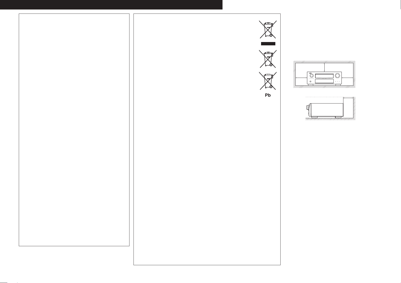
Wall
Wand
Paroi
Parete
Pared
Muur
Vägg
z For proper heat dispersal, do not install this unit in a
confined space, such as a bookcase or similar enclosure.
• More than 0.3 m is recommended.
• Do not place any other equipment on this unit.
z Stellen Sie das Gerät nicht an einem geschlossenen Ort,
wie in einem Bücherregal oder einer ähnlichen Einrichtung
auf, da dies eine ausreichende Belüftung des Geräts
behindern könnte.
• Empfohlen wird über 0,3 m.
• Keine anderen Gegenstände auf das Gerät stellen.
z Pour permettre la dissipation de chaleur requise, n’installez
pas cette unité dans un espace confiné tel qu’une
bibliothèque ou un endroit similaire.
• Une distance de plus de 0,3 m est recommandée.
• Ne placez aucun matériel sur cet appareil.
z Per una dispersione adeguata del calore, non installare
questa apparecchiatura in uno spazio ristretto, come ad
esempio una libreria o simili.
• Si raccomanda una distanza superiore ai 0,3 m.
• Non posizionare alcun altro oggetto o dispositivo su questo
dispositivo.
z Para la dispersión del calor adecuadamente, no instale
este equipo en un lugar confinado tal como una librería o
unidad similar.
• Se recomienda dejar más de 0,3 m alrededor.
• No coloque ningún otro equipo sobre la unidad.
z Plaats dit toestel niet in een kleine afgesloten ruimte, zoals
een boekenkast e.d., omdat anders de warmte niet op
gepaste wijze kan worden afgevoerd.
• Meer dan 0,3 m is aanbevolen.
• Plaats geen andere apparatuur op het toestel.
z För att tillförsäkra god värmeavledning får utrustningen
inte installeras i instängda utrymmen, som t.ex. en
bokhylla eller liknande.
• Mer än 0,3 m rekommenderas.
• Placera ingen annan utrustning ovanpå den här enheten.
Page 5
Getting started
ENGLISH
Thank you for purchasing this DENON product. To ensure proper operation, please read these owner’s manual carefully before using the
product.
After reading them, be sure to keep them for future reference.
Contents
Getting started ·············································································· 1
Accessories ··················································································1
About this manual ·········································································1
Features ························································································2
Cautions on handling ····································································2
Simple version (Simple setup guide) ··························3
Basic version ··········································································12
Connections ·················································································13
Important information ·································································13
Connecting an HDMI-compatible device ····································14
Connecting a TV··········································································16
Connecting a Blu-ray Disc player ················································16
Connecting a DVD player ····························································17
Connecting a set-top box (Satellite tuner/cable TV) ····················17
Connecting a digital video recorder ············································18
Connecting a digital camcorder ··················································18
Connecting a control dock for iPod ·············································19
Connecting an iPod or USB memory device to the USB port ·····19
Connecting an antenna ·······························································20
Connecting a record player ·························································20
Connecting a CD player ······························································21
Connecting a external power amplifier ·······································21
Connecting to a home network (LAN) ········································22
Connecting an external control device ········································23
Playback (Basic operation) ························································· 24
Important information ·································································24
Playing a Blu-ray Disc player/DVD player ····································25
Playing a CD player ·····································································25
Playing an iPod® ·········································································25
Tuning in radio stations ·······························································28
Playing a network audio ······························································30
Playing a USB memory device ····················································38
Selecting a listening mode (Surround mode) ··························40
Standard playback ·······································································40
DENON original surround playback ·············································42
Stereo playback ··········································································42
Direct playback ···········································································42
Pure direct playback····································································42
Advanced version ·······························································43
Speaker installation/connection (Advanced connection) ·······44
Install ··························································································44
Connect ······················································································45
Set up speakers ··········································································48
Playback (Advanced operation) ················································· 50
Convenient functions ··································································50
Playback in ZONE2/ZONE3 (Separate room) ··························57
Audio output ···············································································57
Video output ···············································································57
Playback ······················································································58
Quick select function ··································································58
How to make detailed settings ··················································59
Menu map ··················································································59
Examples of menu and front display ··········································60
Inputting characters ···································································61
Input Setup ·················································································63
Audio/Video Adjust ·····································································68
Manual Setup··············································································74
Information ·················································································86
Operating the connected devices by remote control unit ······87
Operating the main remote control unit ·····································87
Operating the sub remote control unit ·······································91
Information ·············································································94
Part names and functions···························································95
Front panel ··················································································95
Display ························································································96
Rear panel ···················································································97
Remote control unit ····································································98
Other information ·····································································100
Trademark information ······························································100
Surround ···················································································101
Relationship between video signals and monitor output ··········105
Explanation of terms ·································································106
Troubleshooting ········································································108
Resetting the microprocessor ··················································111
Specifications ············································································112
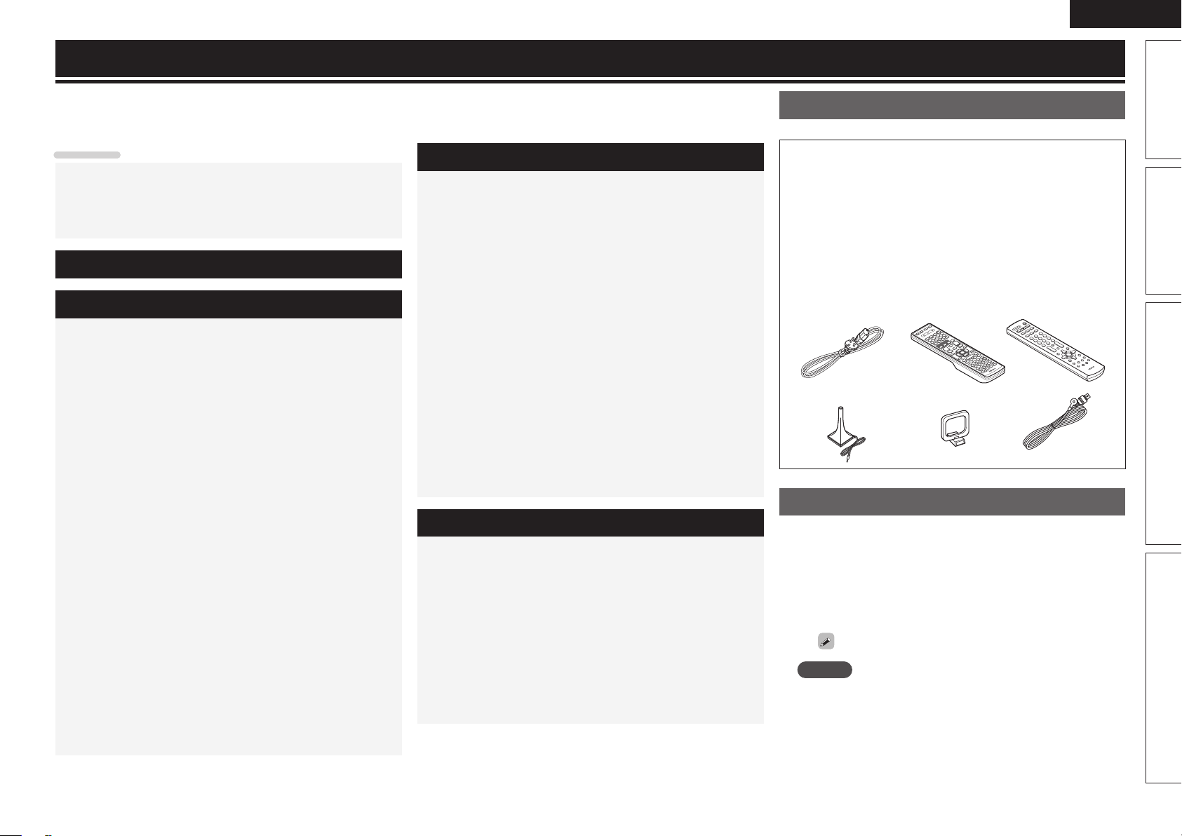
Accessories
Check that the following parts are supplied with the product.
q Owner’s manual ...................................................................... 1
w Service network list ................................................................. 1
e Power cord (Cord length: Approx. 1.8 m) ................................ 1
r Main remote control unit (RC-1146) ........................................ 1
t R6/AA batteries (for RC-1146) ................................................. 2
y Sub remote control unit (RC-1148) .......................................... 1
u R03/AAA batteries (for RC-1148) .............................................2
i Setup microphone
(DM-A409, Cord length: Approx. 6.0 m) .................................. 1
o AM loop antenna ..................................................................... 1
Q0 FM indoor antenna ..................................................................1
i
re
o Q0
y
About this manual
n Operation buttons
The operations described in this manual are based mainly on
remote control operation.
n Symbols
v
NOTE
n Illustrations
Note that the illustrations in these instructions are for explanation
purposes and may differ from the actual unit.
This symbol indicates a reference page on which
related information is described.
This symbol indicates a supplementary information
and tips for operations.
This symbol indicates a supplementary information
and tips for operations.
Basic versionSimple version Advanced version Information
1
Page 6

ENGLISH
Features
Fully Discrete, identical quality and power for all
7 channels (165 W x 7ch)
The unit is equipped with a power amplifier that reproduces highfidelity sound in surround mode with equal quality and power for all
channels, true to the original sound.
The power amplifier circuit adopts a discrete-circuit configuration
that achieves high-quality surround sound reproduction.
Supports HDMI 1.4a with 3D, ARC, Deep Color,
x.v.Color , Auto Lipsync and HDMI control function
This unit can output 3D video signals input from a Blu-ray Disc
player to a TV that supports a 3D system. This unit also supports
the ARC (Audio Return Channel) function, which reproduces TV
sound with this unit via an HDMI cable used for connecting the
unit and a TVz1.
z1 The TV should support the ARC function.
Internet radio, music and photo streaming via
network
This unit can playback audio files and still images such as
photographs that are stored on your computer via a network. You
can also listen to internet radio and a whole host of other online
musicz3 that uses network technology.
z2 An internet connection is required.
z3 You may be required to sign a service agreement with the
6-HDMI inputs and 2-outputs
The unit is equipped with 6 HDMI input connectors for connecting
devices with HDMI connectors, such as a Blu-ray Disc player,
game machine, HD video camera, etc.
z2
companies that provide particular services.
Audyssey DSX™
This unit is equipped with an Audyssey DSX decoder. By
connecting front height speakers to this unit and playing back
through Audyssey DSX, you can experience a more powerful
playback expression in the height audio range. By connecting front
wide speakers, you can experience a more powerful playback
expression in the wide audio range.
Easy to use, Graphical User Interface
This unit is equipped with an easy to see “Graphical User
Interface” that uses menu displays and levels. The use of level
displays increases operability of the unit.
All sources are up-scaled to 1080p
The unit is provided with an HDMI video up-scaling function that
converts an analog video signal input to the unit to a 1080p (HD
resolution) signal and supplies it to a TV via the HDMI connector.
This enables the unit and a TV connected with a single HDMI cable
and any video source to be reproduced precisely with HD level of
quality.
Direct play for iPod® and iPhone® via USB
Music data from an iPod can be played back if you connect the
USB cable supplied with the iPod via the USB port of this unit, and
also an iPod can be controlled with the remote control unit for this
unit.
When an iPod is connected, merely pressing iPod PLAY on the
main unit or remote control unit starts playback of music from the
iPod.
Cautions on handling
• Before turning the power switch on
Check once again that all connections are correct and that there are
no problems with the connection cables.
• Power is supplied to some of the circuitry even when the unit is
set to the standby mode. When going on vacation or leaving home
for long periods of time, be sure to unplug the power cord from the
power outlet.
• About condensation
If there is a major difference in temperature between the inside of
the unit and the surroundings, condensation (dew) may form on
the operating parts inside the unit, causing the unit not to operate
properly.
If this happens, let the unit sit for an hour or two with the power
turned off and wait until there is little difference in temperature
before using the unit.
• Cautions on using mobile phones
Using a mobile phone near this unit may result in noise. If that
occurs, move the mobile phone away from this unit when it is in use.
• Moving the unit
Turn off the power and unplug the power cord from the power
outlet. Next, disconnect the connection cables to other system units
before moving the unit.
• About Care
• Wipe the cabinet and control panel clean with a soft cloth.
• Follow the instructions when using a chemical cleaner.
• Benzene, paint thinner or other organic solvents as well as
insecticide may cause material changes and discoloration if brought
into contact with the unit, and should therefore not be used.
High definition audio support
The unit is equipped with a decoder which supports high-quality
digital audio format for Blu-ray Disc players such as Dolby TrueHD,
DTS-HD Master Audio, etc.
2
Page 7
ENGLISH
Simple
version
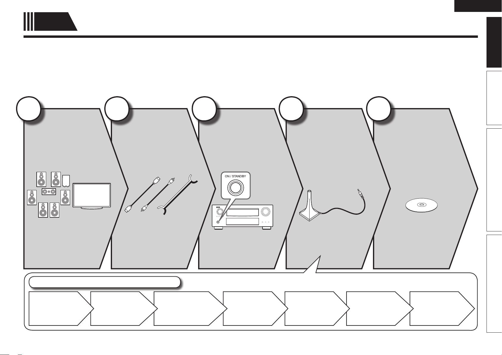
Here, we explain the entire setup procedure, from unboxing the unit to using it in a home theater.
The “Simple version” section provides the speaker installation, connection, and setup methods for the 7.1-channel system with surround
back speakers. For the installing, connecting, and setup methods of speakers other than the 7.1-channel system (with surround back
speakers), see page 44.
Simple version (Simple setup guide)
n Before connecting the unit, turn off the power to all devices.
n For operation of the connected devices, refer to the user manuals for each device.
1
Install
(vpage4)
2
Connect
(vpage4)
3
Turn on
power
(vpage6)
Enjoy better audio, using
the correct install method.
Connect 7.1-channel
speakers, a TV and
Blu-ray Disc player
equipped with an HDMI
connector.
4
Set up
speakers
(vpage6)
Use the setup microphone
(DM-A409) included with
the product, for automatic
setup.
Basic version Advanced version InformationSimple version
5
Play back
disc
(vpage11)
Enjoy Blu-ray Disc and DVD
in surround sound.
Set up speakers (Audyssey® Auto Setup)
STEP 1
Preparation
STEP 2
Speaker
Detection
STEP 3
Measurement
STEP 4
Calculation
STEP 5
Check
STEP 6
Store
Finish
3
Page 8
ENGLISH
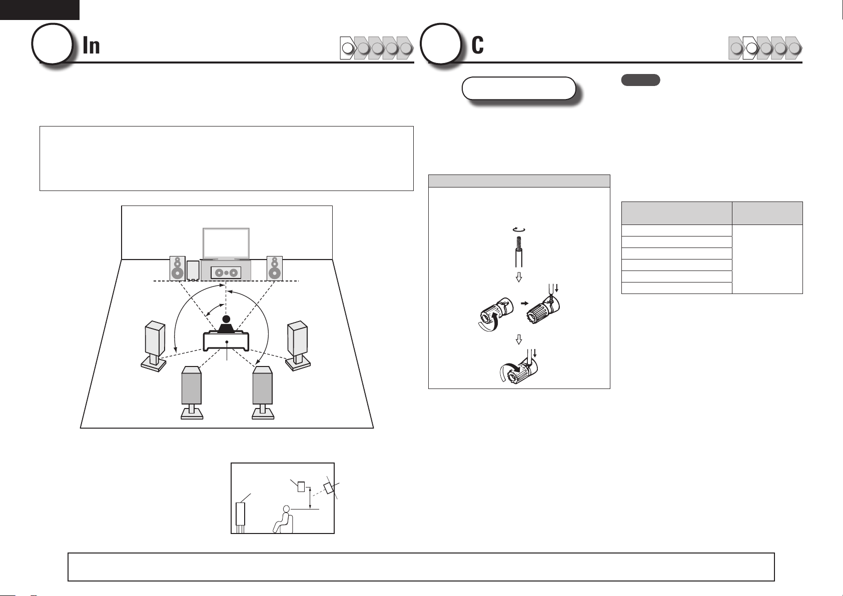
1
Install
1 2 3 4 5
This unit can perform 2.0/2.1 to 7.1-channel surround playback.
This page provides the speaker installation procedure for the
7.1-channel playback using surround back speakers as an example.
The default setting is 7.1-channel. You can also perform 5.1-channel playback.
To perform 5.1-channel playback, connect5.1-channel speakers only.
Use the Audyssey Auto Setup function of this unit to automatically detect the
number of connected speakers and perform optimal settings for the speakers
to be used.
FL FR
SW
C
90 – 110˚
22 – 30˚
135 – 150˚
2
Connect
Speakers
Carefully check the left (L) and right (R)
channels and + (red) and – (black) polarities
on the speakers being connected to the
this unit, and be sure to interconnect the
channels and polarities correctly.
Connecting the speaker cables
Peel off about 10 mm of sheathing from the tip
of the speaker cable, then either twist the core
wire tightly or terminate it.
1 2 3 4 5
NOTE
• Connect so that the speaker cable core wires
do not protrude from the speaker terminal.
The protection circuit may be activated if the
core wires touch the rear panel or if the + and –
sides touch each other (vpage107 “Protection
Circuit”).
• Never touch the speaker terminals while the
power supply is connected. Doing so could
result in electric shock.
• Use speakers with the speaker impedances
shown below.
Speaker terminals
FRONT
CENTER
SURROUND
SURR. BACK / AMP ASSIGN
F.HEIGHT
F.WIDE
Speaker
impedance
6 – 16 Ω
SL
Listening
position
SBL SBR
FL Front speaker (L) • Install the surround speakers in a position 60
FR Front speaker (R)
C Center speaker
SW Subwoofer
SL Surround speaker (L)
SR Surround speaker (R)
SBL Surround back speaker (L)
SBR Surround back speaker (R)
4
The “Simple version” section provides the speaker installation, connection, and setup methods for the 7.1-channel system with surround back speakers.
to 90 cm higher than ear level.
Surround
Front
speaker
speaker
60 – 90 cm
GViewed from the sideH
SR
For the installing, connecting, and setup methods of speakers other than the 7.1-channel system (with surround back speakers), see page 44.
Surround back
speaker
• Point slightly
downwards
Page 9
Audio cable
(sold separately)
ENGLISH
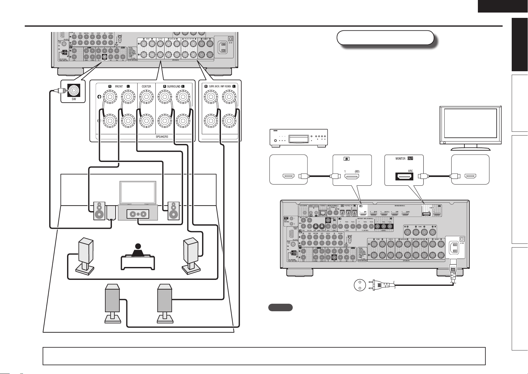
Connect
Blu-ray Disc player and TV
Use only an HDMI (High Definition Multimedia Interface) cable that bears the HDMI
logo (a genuine HDMI product). Using a cable without the HDMI logo (a non-genuine
HDMI product) may result in abnormal playback.
When outputting Deep Color or 1080p, etc., we recommend you use a “High Speed
HDMI cable” or a “High Speed HDMI cable with Ethernet”for enhanced high-quality
playback.
TV
Blu-ray Disc player
Basic version Advanced version InformationSimple version
SL
FL FR
SW
C
Subwoofer with
built-in amplifier
Speaker cables
(sold separately)
SBL SBR
SR
HDMI
OUT
HDMI cable
(sold separately)
To household power outlet
(AC 230 V, 50 Hz)
HDMI cable
(sold separately)
Power cord
(supplied)
HDMI
IN
NOTE
• Do not plug in the power cord until all connections have been completed.
• Do not bundle power cords together with connection cables. Doing so can result in humming or noise.
The “Simple version” section provides the speaker installation, connection, and setup methods for the 7.1-channel system with surround back speakers.
For the installing, connecting, and setup methods of speakers other than the 7.1-channel system (with surround back speakers), see page 44.
5
Page 10
ENGLISH
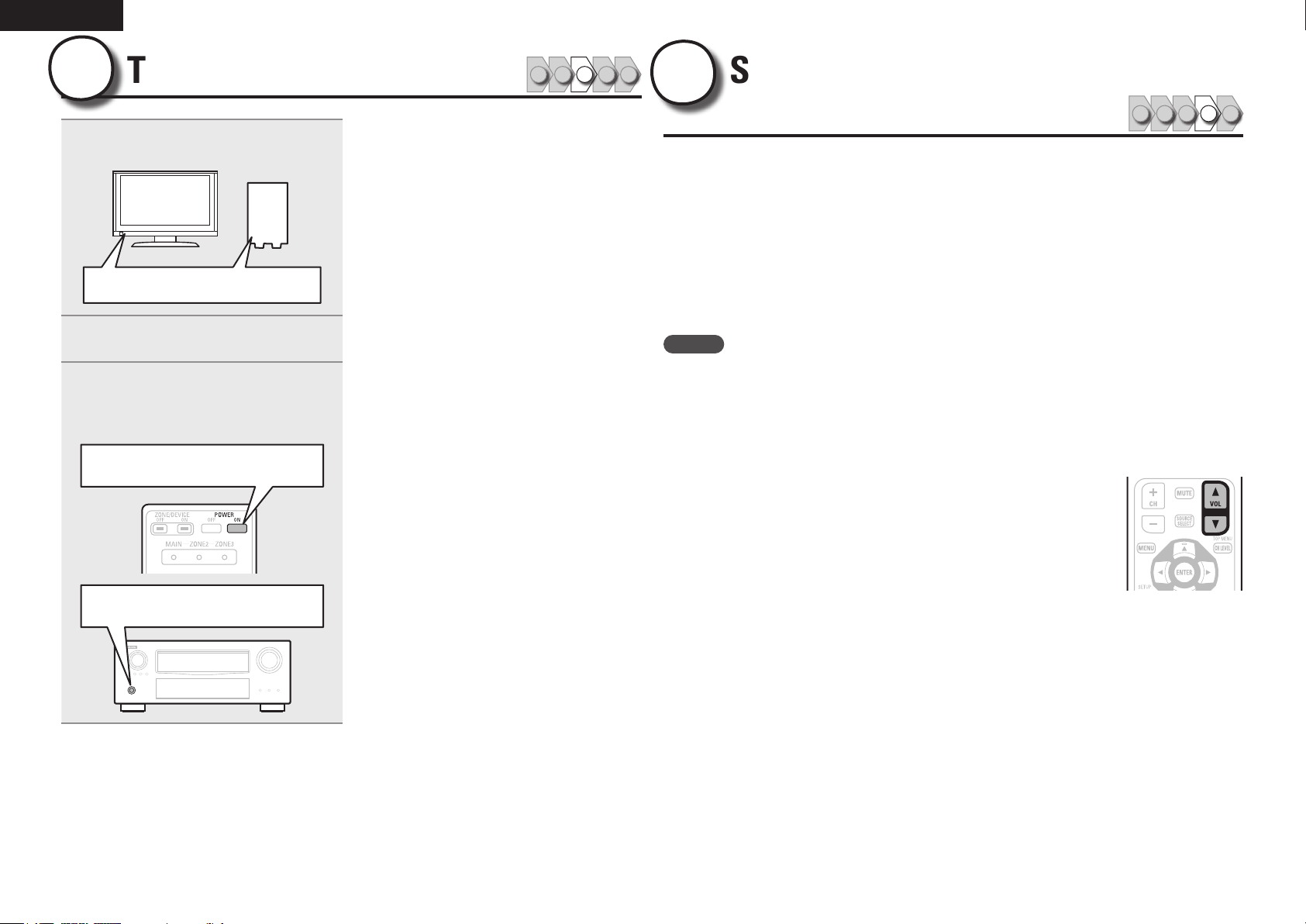
3
1
Turn on power
Turn on the TV and subwoofer
power.
Power on
Change the TV input to the input of
2
this unit.
Press POWER ON to turn on power
3
to the unit.
The power indicator flashes green and the
power turns on.
Power on
1 2 3 4 5
4
The acoustic characteristics of the connected speakers and listening room are
measured and the optimum settings are made automatically. This is called
“Audyssey Auto Setup”.
To perform measurement, place the setup microphone in multiple locations all
around the listening area. For best results, we recommend you measure in six
or more positions, as shown in the illustration (up to eight positions).
• When performing Audyssey Auto Setup, MultEQ® XT/Dynamic EQ®/Dynamic
Volume® functions become active (vpage71, 72).
• To set up the speakers manually, use “Speaker Setup” (vpage75) on the menu.
NOTE
• Make the room as quiet as possible. Background noise can disrupt the room measurements. Close
windows, silence cell phones, televisions, radios, air conditioners, fluorescent lights, home appliances,
light dimmers, or other devices as measurements may be affected by these sounds.
• Cell phones should be placed away from all audio electronics during the measurement process as Radio
Frequency Interference (RFI) may cause measurement disruptions (even if the cell phone is not in use).
• Do not unplug the setup microphone from the main unit until Audyssey Auto Setup is completed.
• Do not stand between the speakers and setup microphone or allow obstacles in the path while the
measurements are being made. This will cause inaccurate readings.
• Loud test sounds may be played during Audyssey Auto setup. This is part of
normal operation. If there is background noise in room, these test signals will
increase in volume.
• Operating
• Measurement cannot be performed when headphones are connected.
Set up speakers
(Audyssey® Auto Setup)
VOL df during the measurements will cancel the measurements.
1 2 3 4 5
Power on
6
Page 11
ENGLISH
Set up speakers (Audyssey® Auto Setup)
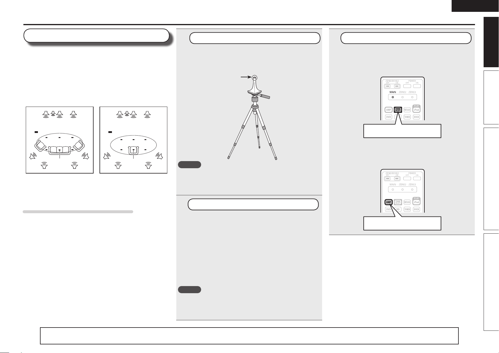
About setup microphone placement
• Measurements are performed by placing the setup microphone
successively at multiple positions throughout the entire listening
area, as shown in GExample qH. For best results, we recommend
you measure in six or more positions, as shown in the illustration
(up to eight positions).
• Even if the listening environment is small as shown in GExample wH,
measuring at multiple points throughout the listening environment
results in more effective correction.
GExample qH GExample wH
FL SW C FR
( : Measuring positions)
SL
FL Front speaker (L) SL Surround speaker (L)
FR Front speaker (R) SR Surround speaker (R)
C Center speaker SBL Surround back speaker (L)
SW Subwoofer SBR Surround back speaker (R)
M
*
SBL SBR
SR
FL SW C FR
( : Measuring positions)
SL
M
*
SBL SBR
SR
About the main listening position (*M)
The main listening position is the position where listeners would
normally sit or where one would normally sit alone within the listening
environment. Before starting Audyssey Auto Setup, place the setup
microphone in the main listening position. Audyssey MultEQ® XT uses
the measurements from this position to calculate speaker distance,
level, polarity, and the optimum crossover value for the subwoofer.
1
Prepare the setup microphone
Mount the setup microphone on a tripod or stand
and place it in the main listening position.
When placing the setup microphone, adjust the height of the
sound receptor to the level of the listener’s ear.
Sound receptor
NOTE
• Do not hold the setup microphone in your hand during
measurements.
• Avoid placing the setup microphone close to a seat back or wall as
sound reflections may give inaccurate results.
2
Set up the subwoofer
Setup
microphone
If using a subwoofer capable of the following
adjustments, set up the subwoofer as shown below.
n When using a subwoofer with a direct mode
Set the direct mode to “On” and disable the volume adjustment
and crossover frequency setting.
n When using a subwoofer without a direct mode
Make the following settings:
• Volume : “12 o’clock position”
• Crossover frequency : “Maximum/Highest Frequency”
• Low pass filter : “Off”
• Standby mode : “Off”
NOTE
When you use two subwoofers, please adjust the subwoofer volume
controls individually so that each subwoofer level is as close as
possible to 75 dB using the test tone (vpage76) before Audyssey
Auto Setup.
3
Set up the remote control unit
n Set up the zone mode
Press ZONE SELECT to switch the zone mode to
“MAIN”.
The “MAIN” indicator lights.
Press ZONE SELECT
n Set up the operation mode
Press AMP to set the remote control unit to amplier
operation mode.
Press AMP
Basic version Advanced version InformationSimple version
The “Simple version” section provides the speaker installation, connection, and setup methods for the 7.1-channel system with surround back speakers.
For the installing, connecting, and setup methods of speakers other than the 7.1-channel system (with surround back speakers), see page 44.
7
Page 12
ENGLISH
Set up speakers (Audyssey® Auto Setup)
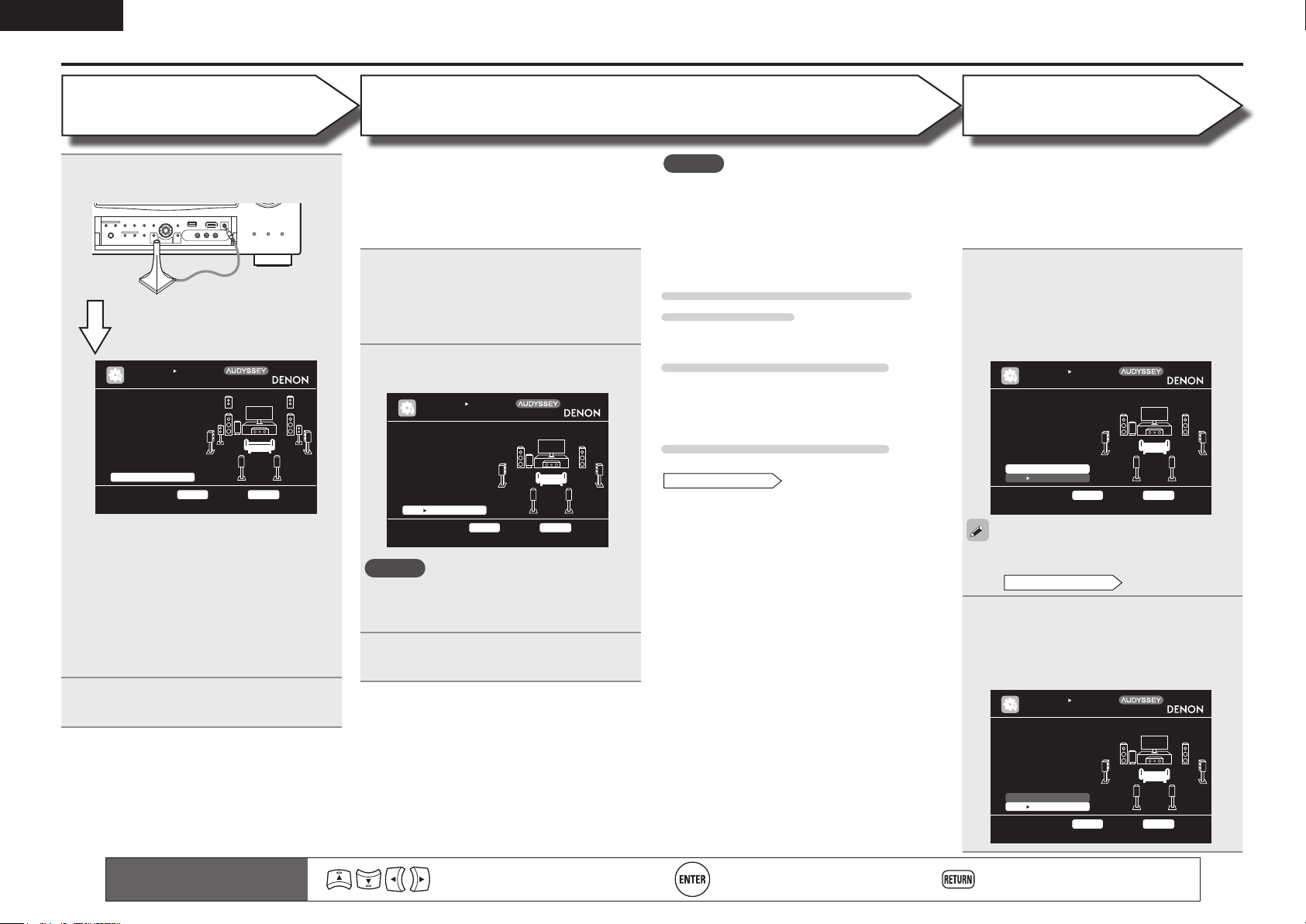
STEP 1
Preparation
Connect the setup microphone to the
4
SETUP MIC jack of this unit.
When the setup microphone is
connected, the following screen is
displayed.
AUTO SE TUP
AUDYSSE Y AUTO SETUP
STE P1 Pre parati on
Con nect t he spe akers
and place them accord ing to th e reco mmenda tio ns in the ma nual.
Set the f ollowi ng
ite ms if necess ary.
Amp Assig n
Cha nnel S elect
Aut o Setu p Star t
Sta rt Aut o Setu p
ENT ER Enter RET URN Ca ncel
This screen provides the method for setting
up 7.1-channel playback using surround back
speakers. For the method of setting up speakers
other than the 7.1-channel system, select “Amp
Assign” and perform step 3 and 4 of “Set up
“Amp Assign”” (vpage49).
If unused channels are set with “Channel Select”,
measuring time can be shortened. For setting,
perform steps 5 to 10 of “Set up “Channel
Select”” (vpage49).
Use ui to select “Auto Setup Start”
5
and then press ENTER.
Mul tEQ XT
[1/ 6]
STEP 2
Speaker Detection
• In STEP 2, you will perform measurements at the
main listening position.
• This step automatically checks the speaker
configuration and speaker size, and calculates the
channel level, distance, and crossover frequency.
It also corrects distortion in the listening area.
Select “Measure” and then press
6
ENTER.
When measuring begins, a test tone is
output from each speaker.
• Measurement requires several minutes.
The detected speakers are displayed.
7
AUTO SE TUP
AUDYSSE Y AUTO SETUP
STE P2 Spk r Dete ct Che ck
Fro nt
Cen ter
Sub woofer
Sur round
S.B ack
F.H eight
F.W ide
Ret ry
Nex t M easure ment
Go to Ste p 3 (M easure ment) after speake r chec k
Yes
Yes
Yes
Yes
2sp krs
No
No
ENT ER Enter RET URN Ca ncel
NOTE
If a connected speaker is not displayed, the
speaker may not be connected correctly. Check
the speaker connection.
Use ui to select “Next 1
8
Measurement” and then press ENTER.
Mul tEQ XT
[2/ 6]
NOTE
If “Caution” is displayed:
Go to “Error messages” (vpage 10), check
any related items, and perform the necessary
procedures.
If the problem is resolved, return and restart
“Audyssey Auto Setup”.
When performing Audyssey Auto
Setup over again
Press ui to select “Retry”, and then press ENTER.
When measuring has stopped
Press RETURN, to the “Cancel Auto Setup?”
prompt is displayed.
Press o to select “Yes”, then press ENTER.
Setting up the speakers again
Repeat the operation from step 4 of
STEP1 Preparation
.
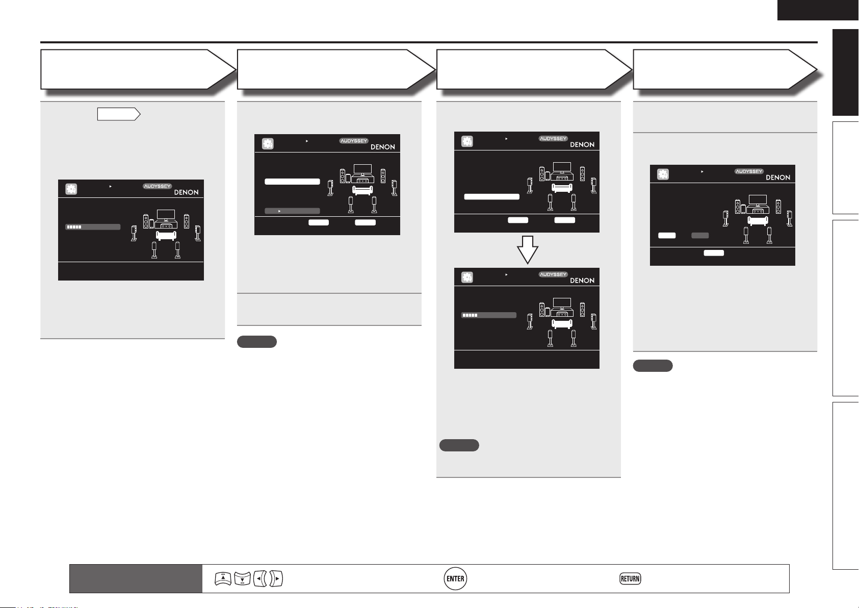
STEP 3
Measurement
• In STEP 3, you will perform measurements at
multiple positions (two to eight positions) other
than the main listening position.
• You can achieve a more effective correction of
distortion within the listening area by performing
measurements at multiple positions.
Move the setup microphone to
9
position 2, use ui to select
“Measure”, and then press ENTER.
The measurement of the second position
starts. Measurements can be made in up to
eight positions.
AUTO SE TUP
AUDYSSE Y AUTO SETUP
STE P3 Mea sureme nt
Ple ase pl ace th e microp hone a t ear height
at 2nd li stenin g
pos ition.
Mea sure
Nex t C alcula tion
Sta rt nex t meas uremen t. Tes t Tone will start
ENT ER Enter RET URN Ca ncel
If you want to omit measurements from the next
position onward, select “Next 1 Calculation”.
STEP4 Calculation
(Go to
Repeat step 9, measuring positions 3
10
to 8.
When measurement of position 8 is
completed, a “Measurements finished.”
message is displayed.
AUTO SE TUP
AUDYSSE Y AUTO SETUP
STE P3 Mea sureme nt
Mea sureme nts fi nished .
Mul tEQ XT
[3/ 6]
)
Mul tEQ XT
[3/ 6]
Ret ry
Nex t C alcula tion
Pro ceed t o Step 4 (An alyze)
8
Remote control operation
buttons
Move the cursor
(Up/Down/Left/Right)
Confirm the setting Return to previous menu
ENT ER Enter RET URN Ca ncel
Page 13
ENGLISH
Set up speakers (Audyssey® Auto Setup)
STEP 4
Calculation
On the
11
to select “Next 1 Calculation”, and
then press ENTER.
Measuring results are analyzed, and the
frequency response of each speaker in the
listening room is determined.
STE P4 Cal culati on
Now calcu lating ...
Ple ase wa it.
25%
• Analysis takes several minutes to complete. The
time required for this analysis depends on the
number of speakers connected.
The more connected speakers there are, the
longer it takes to perform analysis.
STEP3
AUTO SE TUP
AUDYSSE Y AUTO SETUP
screen, use ui
Mul tEQ XT
[4/ 6]
STEP 5
Check
Use ui to select the item you want
12
to check, and then press ENTER.
AUTO SE TUP
AUDYSSE Y AUTO SETUP
STE P5 Che ck
Che ck pro cessin g result s. To procee d,pres s
“Ne xt”
Spk r Conf ig Che ck
Dis tance Check
Ch. Leve l Chec k
Cro ssover Check
Nex t S tore
Sel ect it em to check
ENT ER Enter RET URN Ca ncel
• Subwoofers may measure a greater reported
distance than the actual distance due to added
electrical delay common in subwoofers.
• If you want to check another item, press
RETURN.
Use ui to select “Next 1 Store”
13
and then press ENTER.
NOTE
• If the result differs from the actual connection
status, or if “Caution!” is displayed, see “Error
messages” (vpage10). Then carry out Audyssey
Auto Setup again.
• If the result still differs from the actual connection
status after remeasurement or the error message
still appears, it is possible that the speakers
are not connected properly. Turn this unit off,
check the speaker connections and repeat the
measurement process from the beginning.
• If you change speaker positions or orientation,
perform Audyssey Auto Setup again to find the
optimal equalizer settings.
Mul tEQ XT
[5/ 6]
STEP 6
Store
Select “Store” and then press ENTER.
14
Save the measurement results.
AUTO SE TUP
AUDYSSE Y AUTO SETUP
STE P6 Sto re
Pre ss “St ore” t o stor e
cal culati on res ults.
Sto re
App ly and store measu rement resul t
AUTO SE TUP
AUDYSSE Y AUTO SETUP
STE P6 Sto re
Now stori ng...
Ple ase wa it.
25%
ENT ER Enter RET URN Ca ncel
• Saving the results requires about 10 seconds.
• If the measuring results are not to be saved,
press RETURN. A message “Cancel Auto
Setup?” will be displayed. Press o then select
“Yes”. All the measured Audyssey Auto Setup
data will be erased.
NOTE
During saving of measurement results, be sure
not to turn off the power.
Mul tEQ XT
[6/ 6]
Mul tEQ XT
[6/ 6]
Finish
Unplug the setup microphone from
15
the unit’s SETUP MIC jack.
Set Dynamic Volume®.
16
AUTO SE TUP
AUDYSSE Y AUTO SETUP
Fin ish
Sto ring c omplet e.
Aut o Setu p is n ow
fin ished. Pleas e unpl ug
mic rophon e.
Tur n on D ynamic Volum e?
Yes No
Tur n Dyna mic Vo lume o n and exit A uto Se tup
ENT ER Exit
• For details of Dynamic Volume settings, see
page 72.
n When turning Dynamic Volume on
Use o to select “Yes“, and then press ENTER.
• The unit automatically enters “Evening” mode.
n When turning Dynamic Volume off
Use p to select “No“, and then press ENTER.
NOTE
After performing Audyssey Auto Setup, do not
change the speaker connections or subwoofer
volume. In event of a change, perform Audyssey
Auto Setup again.
Mul tEQ XT
[6/ 6]
Basic version Advanced version InformationSimple version
Remote control operation
buttons
Move the cursor
(Up/Down/Left/Right)
Confirm the setting Return to previous menu
9
Page 14
ENGLISH
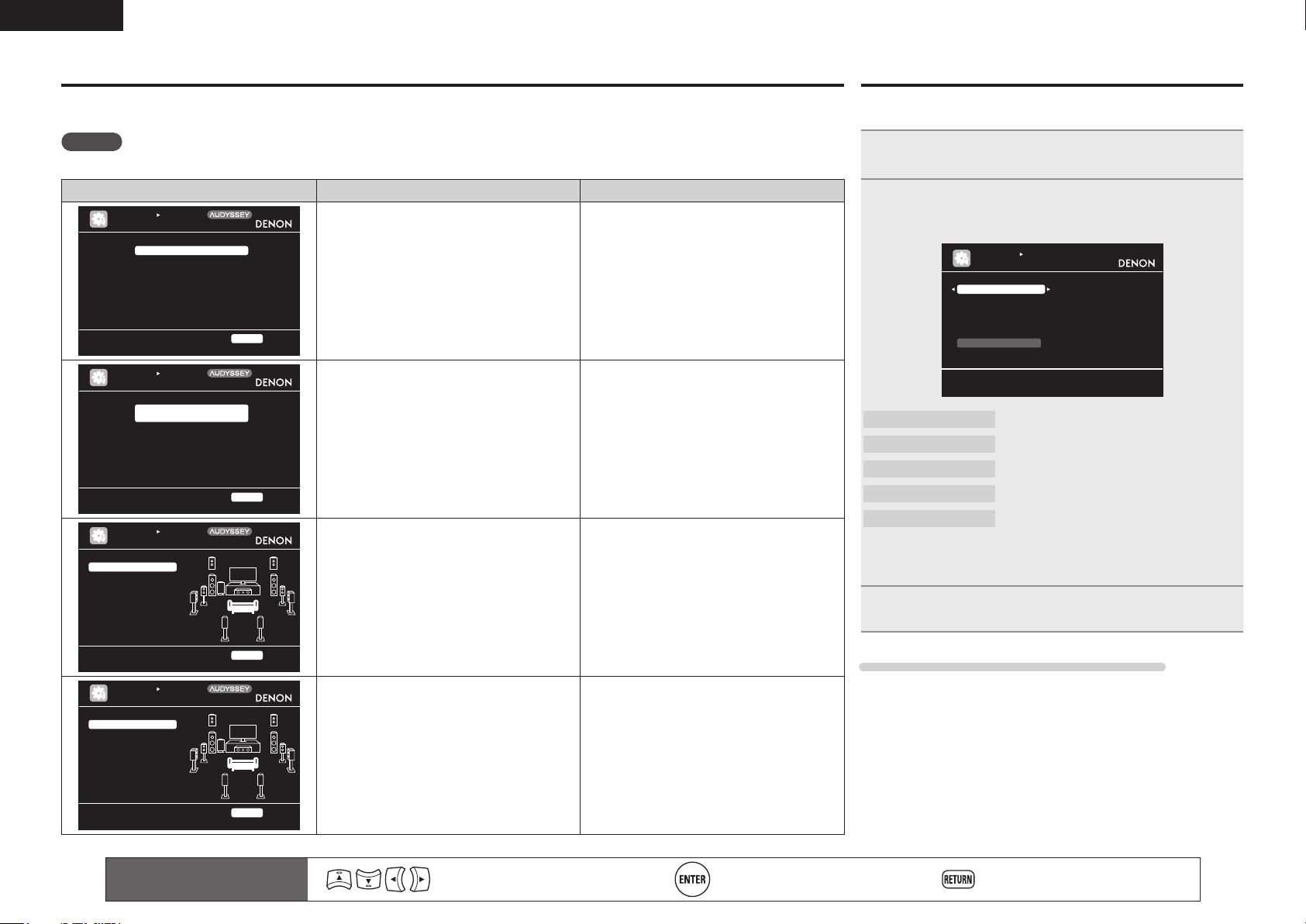
Error messages
An error message is displayed if Audyssey® Auto Setup could not be completed due to speaker placement, the measurement environment, etc.
If this happens, check the relevant items, be sure to take the necessary measures, then perform Audyssey Auto Setup over again.
NOTE
Be sure to turn off the power before checking speaker connections.
Examples Error details Measures
AUTO SE TUP
AUDYSSE Y AUTO SETUP
No microp hone o r Spea ker
Che ck cau se of proble m!
AUTO SE TUP
AUDYSSE Y AUTO SETUP
Amb ient n oise i s too high
or Level is too low
Che ck cau se of proble m!
AUTO SE TUP
AUDYSSE Y AUTO SETUP
Cau tion!
Fro nt R Non e
Cau tion!
Ret ry
Cau tion!
Ret ry
Mul tEQ XT
RET URN Ca ncel
Mul tEQ XT
RET URN Ca ncel
Mul tEQ XT
• The connected setup microphone is broken,
or a device other than the supplied setup
microphone is connected.
• Not all speakers could be detected.
• The front L speaker was not properly
detected.
• There is too much noise in the room for
accurate measurements to be made.
• Speaker or subwoofer sound is too low for
accurate measurements to be made.
• The displayed speaker could not be detected. • Check the connections of the displayed
• Connect the included setup microphone to
the SETUP MIC jack of this unit.
• Check the speaker connections.
• Either turn off any device generating noise
or move it away.
• Perform again when the surroundings are
quieter.
• Check the speaker installation and the
direction in which the speakers are facing.
• Adjust the subwoofer’s volume.
speaker.
Parameter Check
This function enables you to check the measurement results and
equalizer characteristics after Audyssey Auto Setup.
Use ui to select “Parameter Check” and then
1
press ENTER or p.
Use ui to select the item you want to check, then
2
press ENTER or p.
Measurement results for each speaker are displayed.
AUTO SE TUP
PARAMET ER CHECK
Spe aker C onfig Check
Dis tance Check
Cha nnel L evel C heck
Cro ssover Check
EQ Check
Res tore
Sho w spea ker co nfigur ation result
Speaker Config. Check
Distance Check
Channel Level Check
Crossover Check
EQ Check
• If “EQ Check” is selected in step 2, press
curve (“Audyssey” or “Audyssey Flat”) to be checked.
Use o p to switch the display between the different speakers.
Check the speaker configuration.
Check the distance.
Check the channel level.
Check the crossover frequency.
Check the equalizer.
ui to select equalizing
Ret ry
Che ck cau se of proble m!
AUTO SE TUP
AUDYSSE Y AUTO SETUP
Cau tion!
Fro nt L P hase
Ret ry
Ski p
Che ck cau se of proble m!
10
RET URN Ca ncel
Mul tEQ XT
RET URN Ca ncel
Remote control operation
buttons
• The displayed is connected with the
polarities reversed.
Move the cursor
(Up/Down/Left/Right)
• Check the polarities of the displayed
speaker.
• For some speakers, this error message may
be displayed even if the speaker is properly
connected. If you are sure the connection is
correct, press ui to select “Skip”, then
press ENTER.
Confirm the setting Return to previous menu
Press RETURN.
3
The confirmation screen reappears. Repeat steps 2.
Retrieving Audyssey Auto Setup settings
If you set “Restore” to “Yes”, you can return to Audyssey Auto Setup
measurement result (value calculated at the start by MultEQ® XT)
even when you have changed each setting manually.
Page 15
ENGLISH
5
1
2
Play back disc
Press BD to switch an input source
for a player used for playback.
Play the component connected to
this unit.
Make the necessary settings on the
player (language setting, subtitles
setting, etc.) beforehand.
Adjust the sound volume.
3
VOL d ........................................... Volume up
VOL f ...................................... Volume down
MUTE .................................................. Muting
Set the listening mode.
Set the listening mode according to the playback contents
4
(cinema, music, etc.) or according to your liking (vpage 40
“Selecting a listening mode (Surround mode)”).
1 2 3 4 5
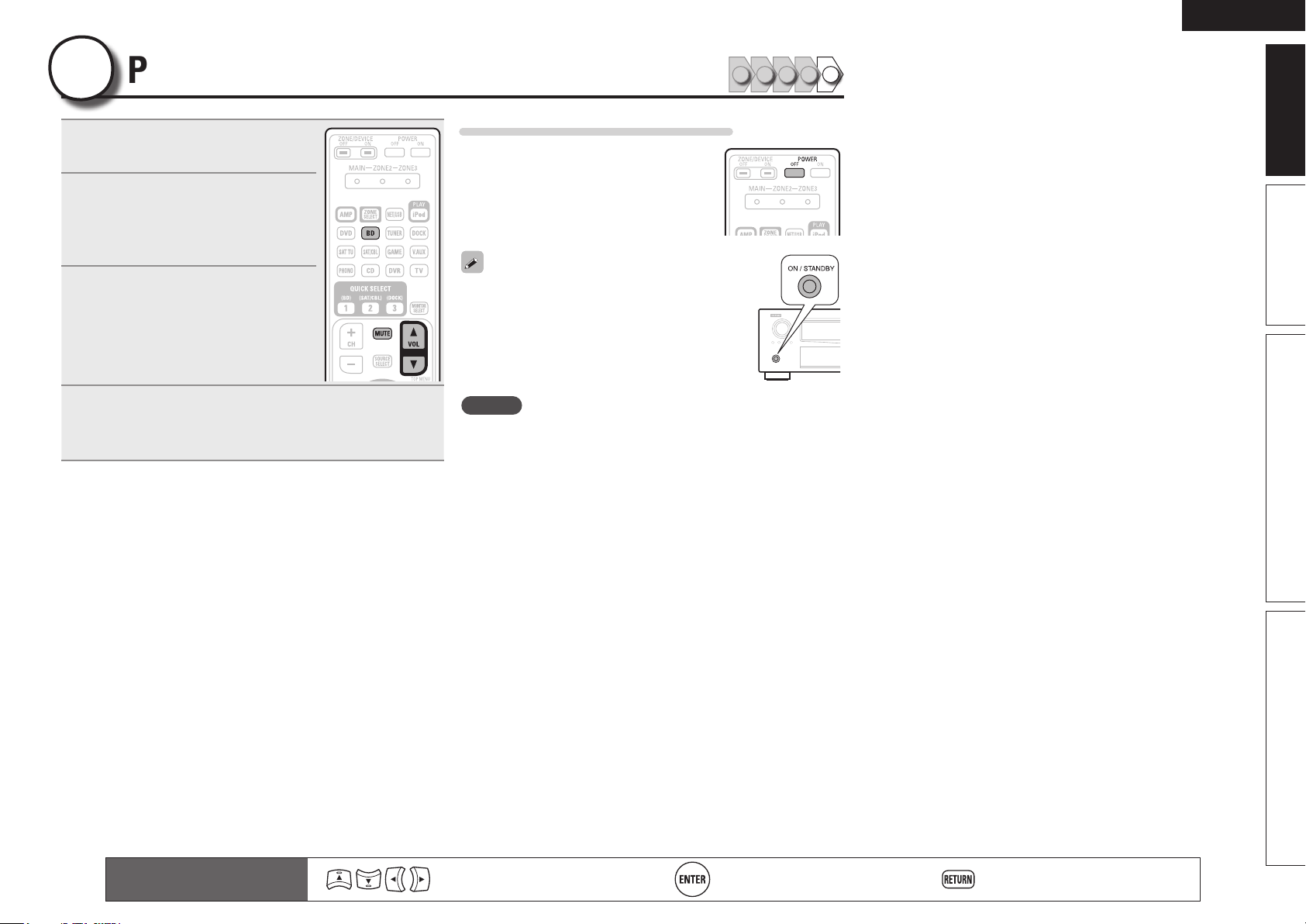
When power is switched to standby
Press POWER OFF.
GPower indicator status in standby modeH
• Normal standby : Off
• When “HDMI Control” is set to “ON” : Red
• When “Network Standby” is set to “ON” :
Red
You can also switch the power to standby by
pressing ON/STANDBY on the main unit.
NOTE
During power standby, a minimal amount of power is consumed. To
totally cut off the power, remove the power cord from the power
outlet.
Basic version Advanced version InformationSimple version
Remote control operation
buttons
Move the cursor
(Up/Down/Left/Right)
Confirm the setting Return to previous menu
11
Page 16
ENGLISH
Basic
version
Basic version
Here, we explain the connections and basic operation methods for this unit.
F Connections vpage13
F Playback (Basic operation) vpage24
F Selecting a listening mode (Surround mode) vpage40
n Refer to the pages indicated below for information on connecting and playing back the various
media and external devices.
12
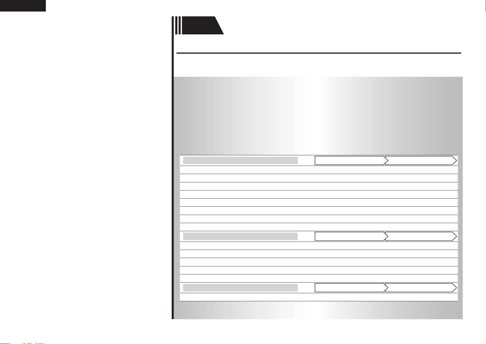
Audio and Video
TV
Blu-ray Disc player
DVD player
Set-top box (Satellite tuner or cable TV)
Digital video recorder
Game console
Digital camcorder
Control dock for iPod
Audio
®
iPod
USB memory device
CD player
Radio
Record player
Network
Network
For speaker connections, see page 4.
PlaybackConnection
vpage15, 16
vpage15, 16 vpage25
vpage15, 17 vpage25
vpage15, 17
vpage15, 18
vpage15
vpage18
vpage19 vpage25
vpage19 vpage27
vpage19 vpage38
vpage21 vpage25
vpage20 vpage28
vpage20
vpage22 vpage30
–
–
–
–
–
PlaybackConnection
–
PlaybackConnection
Page 17
ENGLISH
Connections
Important information
• Make connections as follows before using this unit. Select an appropriate connection type
according to the components to be connected.
• You may need to make some settings on this unit depending on the connection method. Refer to
each description for more information.
• Select the cables (sold separately) according to the components being connected.
NOTE
• Do not plug in the power cord until all connections have been completed.
• When making connections, also refer to the operating instructions of the other components being
connected.
• Be sure to connect the left and right channels properly (left with left, right with right).
• Do not bundle power cords together with connection cables. Doing so can result in noise.
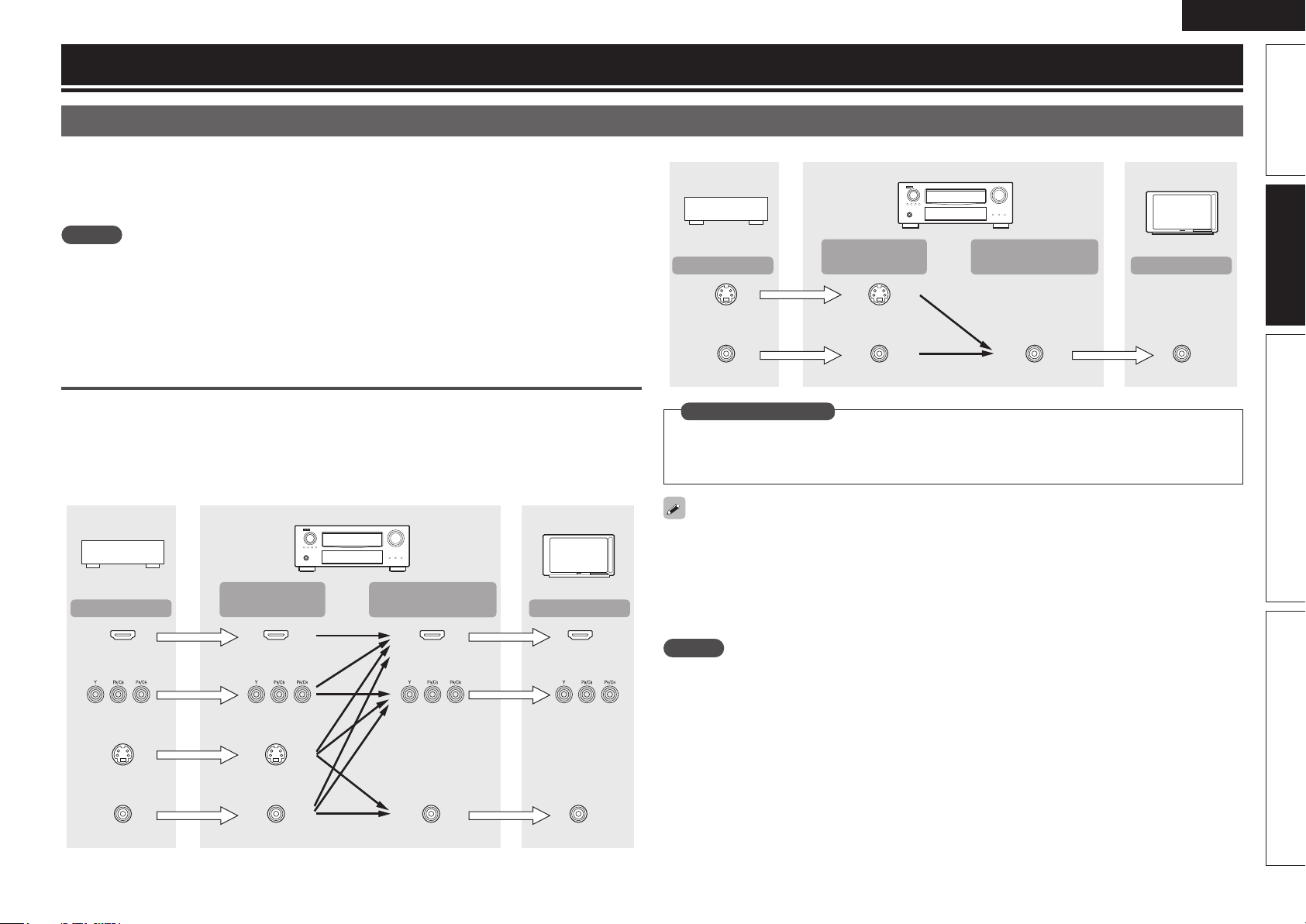
Converting input video signals for output
(Video conversion function)
This unit is equipped with four types of video input connectors (HDMI, Component video, S-Video and
video) and three types of video output connectors (HDMI, Component video and video).
Use the connectors corresponding to the components to be connected.
This function automatically converts various formats of video signals input to this unit into the formats used
to output the video signals from this unit to a monitor.
GFlow of video signals for MAIN ZONEH
Video device
Output
HDMI connector
Component video
connectors
Input
(IN)
HDMI connector
Component video
connectors
This unit
Output
(MONITOR OUT)
HDMI
connector
Component video
connectors
Monitor
Input
HDMI connector
Component video
connectors
GFlow of video signals for ZONE2H
Video device
Output
S-Video connector
Video connector
This unit
Input
(IN)
S-Video connector
Video connector Video connector Video connector
Output
(MONITOR OUT)
Monitor
Input
in Set as Necessary
• Set when not using the video conversion function.
“Video Convert” (vpage66)
• Set when changing the resolution of the video signal.
“Resolution” (vpage66)
• The video conversion function supports the NTSC, PAL, SECAM, NTSC 4.43, PAL-N, PAL-M and PAL-60
formats.
• The resolution of the video signal input to this unit’s HDMI connector is the one set at “Resolution”
(vpage66). (1080p HDMI signals and 1080p component signals are output at 1080p, regardless of the
setting.)
• Resolutions of HDMI-compatible TVs can be checked at “HDMI Monitor 1 Information” or “HDMI
Monitor 2 Information” (vpage86).
NOTE
• HDMI signals cannot be converted into analog signals.
• When a non-standard video signal from a game machine or some other source is input, the video
conversion function might not operate.
• Component video input signals cannot be converted into Video format.
• A menu is output via the HDMI connector or component video connector.
Simple version Advanced version InformationBasic version
S-Video connector
Video connector
S-Video connector
Video connector
Video connector
Video connector
13
Page 18
ENGLISH
Important information
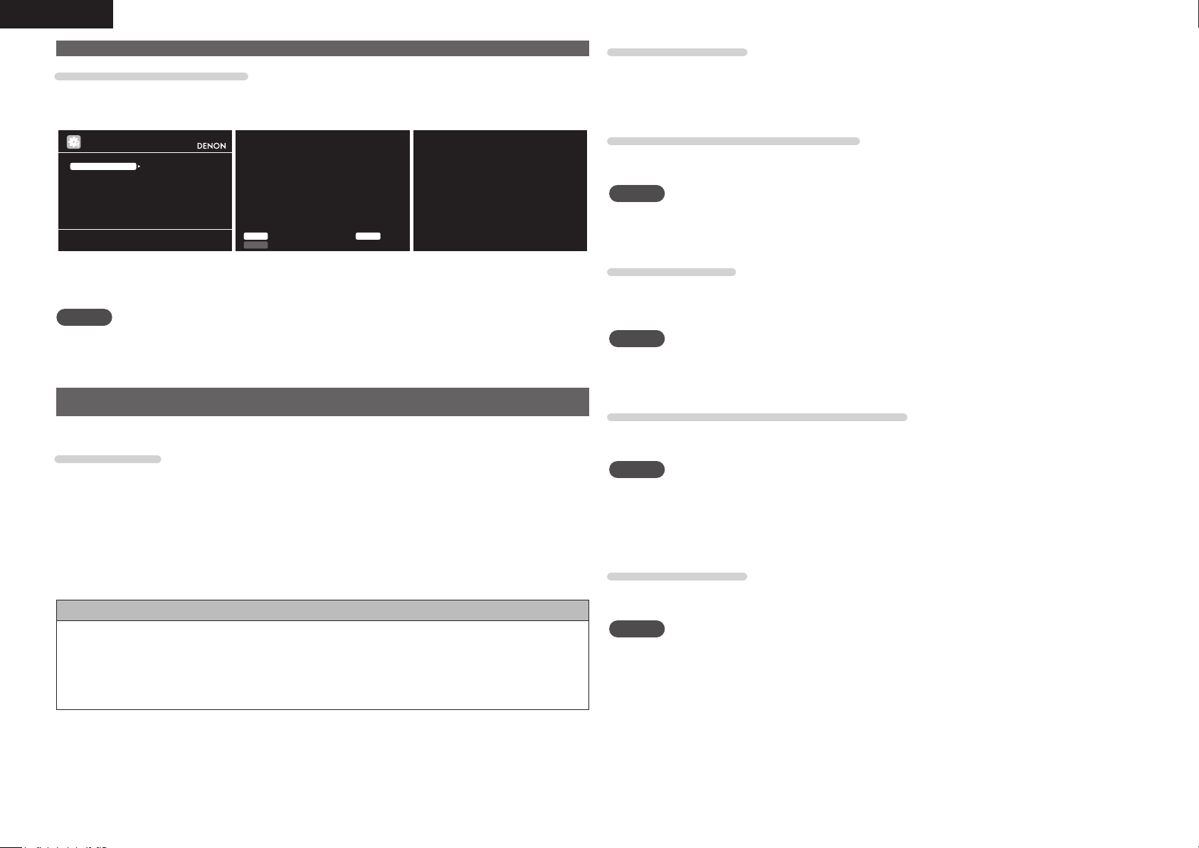
Examples of screen display
• Menu screen • Status display screen
When the input source is
When the volume is adjusted
switched
MENU
Audi o/Vide o Adjus t
Info rmatio n
Auto Setup
Manu al Set up
Inpu t Setu p
Adju st var ious au dio an d vide o param eters
BD
Inpu t Auto
STER EO
Mode
Mast er Vo lume -80.0d B
Status display: The operating status appears briefly on the screen
when the input source is switched or the volume is
changed.
NOTE
• If you operate the menu while playing back 3D video content, the playback video is replaced by the menu
screen. The playback video is not displayed behind the menu screen.
• This unit does not show the status display while playing back 3D video content.
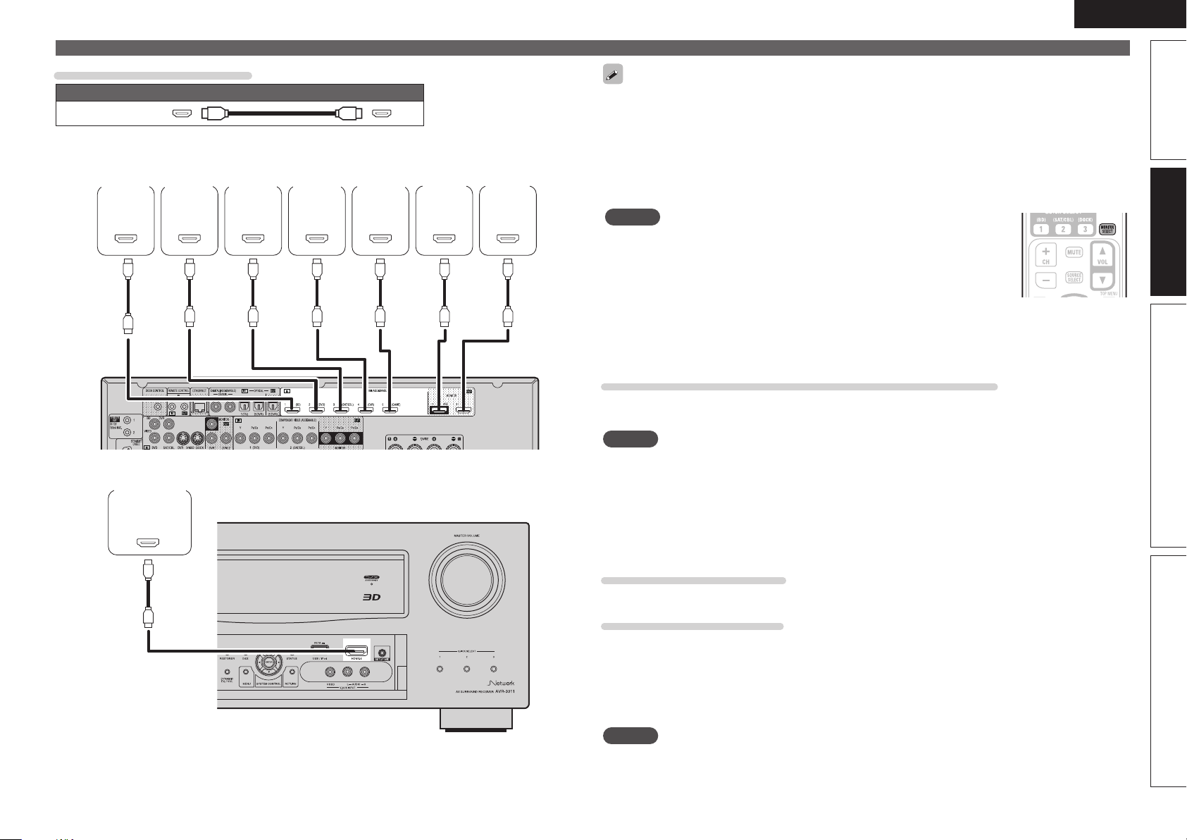
Connecting an HDMI-compatible device
You can connect up to six HDMI-compatible devices to the unit.
HDMI function
This unit supports the following HDMI functions:
• 3D
• Deep Color (vpage106)
• Auto Lip Sync (vpage77, 106)
• x.v.Color, sYCC601 color, Adobe RGB color, Adobe YCC601 color (vpage106, 107)
• High definition digital audio format
• ARC (Audio Return Channel)
• Content Type
• CEC (HDMI control)
Copyright protection system
In order to play back digital video and audio such as BD-Video or DVD-Video via HDMI connection, both
this unit and TV or the player need to support the copyright protection system known as HDCP (Highbandwidth Digital Content Protection System). HDCP is copyright protection technology comprised of
data encryption and authentication of the connected AV device. This unit supports HDCP.
• If a device that does not support HDCP is connected, video and audio are not output correctly. Read
the owner’s manual of your television or player for more information.
About HDMI cables
• When a device supporting Deep Color signal transfer is connected, use a cable compatible “High Speed
HDMI cable” or “High Speed HDMI cable with Ethernet”.
• When the ARC function is used, connect a device with a ”Standard HDMI cable with Ethernet” or “High
Speed HDMI cable with Ethernet” for HDMI 1.4a.
HDMI control function (vpage50)
This function allows you to operate external devices from the receiver and operate the receiver from
external devices.
NOTE
• The HDMI control function may not work depending on the device it is connected to and its settings.
• You cannot operate a TV or Blu-ray Disc player/DVD player that is not compatible with the HDMI control
function.
About 3D function
This unit supports input and output of 3D (3 dimensional) video signals of the HDMI 1.4a standards.
For playing the 3D video content, a player, and a TV that support the 3D function of the HDMI 1.4a
standards are required in addition to this unit.
NOTE
• If you operate the menu while playing back 3D video content, the playback video is replaced by the menu
screen. The playback video is not displayed behind the menu screen.
• This unit does not show the status display while playing back 3D video content.
About ARC (Audio Return Channel) function
The Audio Return Channel in HDMI 1.4a enables a TV, via a single HDMI cable, to send audio data “upstream”
to this unit.
NOTE
• To enable the ARC function, set “HDMI Control” to “ON” (vpage78).
• ARC function is only supported for the HDMI MONITOR OUT 1 connector. In order to use the ARC
function, connect the television to the HDMI MONITOR OUT 1 connector.
• When connecting a TV that does not support the ARC function, a separate connection using an audio
cable is required. In this case, refer to “Connecting a TV” (vpage16) for the connection method.
About Content Type
The HDMI specification version 1.4a enables simple, automated picture setting selection with no user
intervention.
NOTE
To enable the Content Type, set “Video Mode” to “Auto” (vpage66).
14
Page 19
ENGLISH
Cables used for connections
Audio and video cable (sold separately)
HDMI cable
• This interface allows transfer of digital video signals and digital audio signals over a single HDMI cable.
Blu-ray
Disc
player
HDMI
OUT
Digital
camcorder
HDMI
OUT
DVD
player
HDMI
OUT
Set-top
box
HDMI
OUT
Digital
video
recorder
HDMI
OUT
Game
console
HDMI
OUT
TV 1
HDMI
IN
TV 2
HDMI
IN
GRear panelH
Connecting an HDMI-compatible device
• When this unit is connected to other devices with HDMI cables, connect this unit and TV also with an
HDMI cable.
• When connecting a device that supports Deep Color transmission, please use a “High Speed HDMI
cable” or “High Speed HDMI cable with Ethernet”.
• Video signals are not output if the input video signals do not match the monitor’s resolution. In this case,
switch the Blu-ray Disc/DVD player’s resolution to a resolution with which the monitor is compatible.
• When this unit and monitor are connected with an HDMI cable, if the monitor is not compatible with
HDMI audio signal playback, only the video signals are output to the monitor.
NOTE
• The HDMI signal is not simultaneously output to HDMI MONITOR 1 and HDMI
MONITOR 2. Select the connector that you want to use in advance using
“Monitor Out” (vpage77) in the menu, or by pressing the MONITOR SELECT
button on the remote control.
• HDMI control function is only supported for the HDMI MONITOR OUT 1
connector. In order to use the HDMI control function, connect the television to
the HDMI MONITOR OUT 1 connector.
• The audio signal from the HDMI output connector (sampling frequency, number of channels, etc.) may be
limited by the HDMI audio specifications of the connected device regarding permissible inputs.
Connecting to a device equipped with a DVI-D connector
When an HDMI/DVI conversion cable (sold separately) is used, the HDMI video signals are converted to
DVI signals, allowing connection to a device equipped with a DVI-D connector.
NOTE
• No sound is output when connected to a device equipped with a DVI-D connector. Make separate audio
connections.
• Signals cannot be output to DVI-D devices that do not support HDCP.
• Depending on the combination of devices, the video signals may not be output.
n Settings related to HDMI connections
Set as necessary. For details, see the respective reference pages.
Simple version Advanced version InformationBasic version
GFront panelH
Input Assign (vpage64)
Set this to change the HDMI input connector to which the input source is assigned.
HDMI Setup (vpage77)
Make settings for HDMI video/audio output.
• RGB Range • HDMI Control
• Auto Lip Sync • Standby Source
• HDMI Audio Out • Power Off Control
• Monitor Out
NOTE
The audio signals output from the HDMI connectors are only the HDMI input signals.
15
Page 20
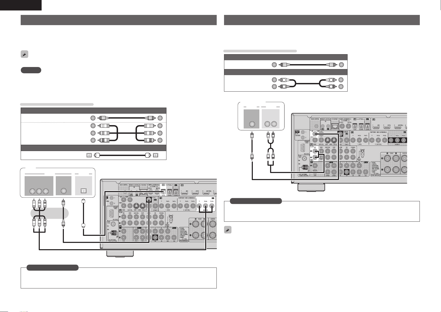
ENGLISH
Connecting a TV
• Select the connector to use and connect the device.
• For video connections, see “Converting input video signals for output (Video conversion function)”
(vpage13).
• For instructions on HDMI connections, see “Connecting an HDMI-compatible device” (vpage14).
To listen to TV audio through this device, use the optical digital connection.
NOTE
This connection is not required when a TV compatible with the ARC function (Audio Return Channel (HDMI
1.4a standard function) is connected to this unit via an HDMI connection.
For details, see “About ARC (Audio Return Channel) function” (vpage 14) or refer to the instruction
manual for your TV.
Cables used for connections
Video cable (sold separately)
Video cable
Component video
cable
Optical cable
TV
Y P
IN
B PR
VIDEO
COMPONENT VIDEO
(Yellow)
(Green)
(Blue)
(Red)
Audio cable (sold separately)
AUDIO
VIDEO
IN
OPTICAL
OUT
Connecting a Blu-ray Disc player
• You can enjoy video and audio from a Blu-ray Disc.
• Select the connector to use and connect the device.
• For instructions on HDMI connections, see “Connecting an HDMI-compatible device” (vpage14).
Cables used for connections
Video cable (sold separately)
Video cable
Audio cable
Blu-ray Disc
(Yellow)
Audio cables (sold separately)
(White)
(Red)
L
R
player
VIDEO
VIDEO
OUT
AUDIO
AUDIO
OUT
L
L
RL
R
R
L
R
in Set as Necessary
Set this to change the digital input connector or component video input connector to which the input
source is assigned.
“Input Assign” (vpage64)
16
in Set as Necessary
Set this to change the digital input connector or component video input connector to which the input
source is assigned.
“Input Assign” (vpage64)
For HD audio (Dolby TrueHD, DTS-HD, Dolby Digital Plus and DTS Express) playback, connect with HDMI
(vpage14 “Connecting an HDMI-compatible device”).
Page 21
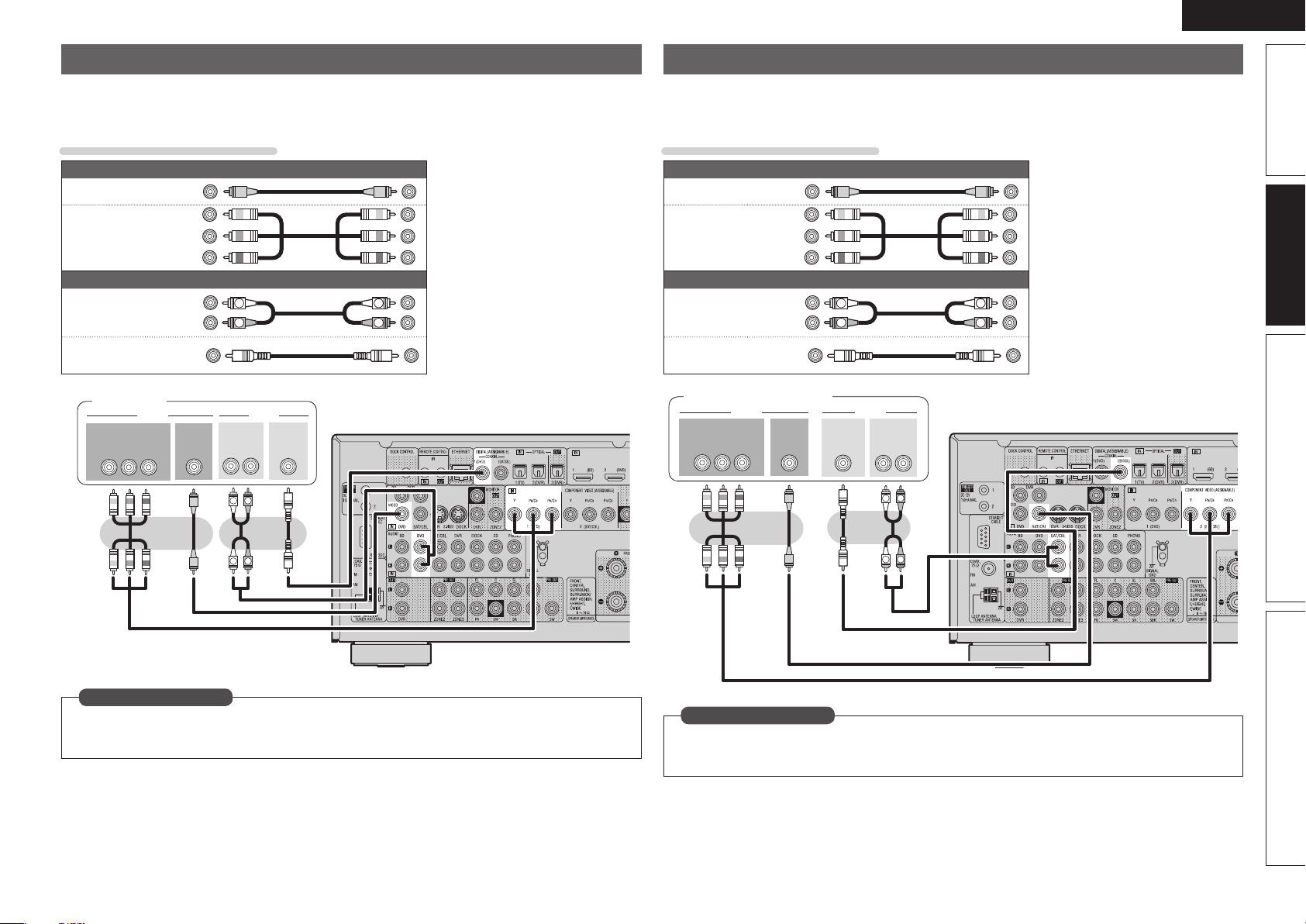
ENGLISH
Connecting a DVD player
• You can enjoy video and audio from a DVD.
• Select the connector to use and connect the device.
• For instructions on HDMI connections, see “Connecting an HDMI-compatible device” (vpage14).
Cables used for connections
Video cable (sold separately)
Video cable
Component
video cable
Audio cable
Coaxial
digital cable
DVD player
COMPONENT VIDEO
Y P
(Yellow)
(Green)
(Blue)
(Red)
Audio cables (sold separately)
(White)
(Red)
(Orange)
VIDEO AUDIO
VIDEO
OUT
B PR
OUT
L
R
AUDIO
OUT
L
RL
R
COAXIAL
OUT
L
R
Connecting a set-top box (Satellite tuner/cable TV)
• You can watch satellite or cable TV.
• Select the connector to use and connect the device.
• For instructions on HDMI connections, see “Connecting an HDMI-compatible device” (vpage14).
Cables used for connections
Video cable (sold separately)
Video cable
Component
video cable
Audio cable
Coaxial
digital cable
Satellite tuner/Cable TV
COMPONENT VIDEO
OUT
Y P
(Yellow)
(Green)
(Blue)
(Red)
Audio cables (sold separately)
L
R
COAXIAL
OUT
VIDEO
B PR
(White)
(Red)
(Orange)
VIDEO
OUT
AUDIO
AUDIO
OUT
L
L
R
RL
R
Simple version Advanced version InformationBasic version
R
L
in Set as Necessary
Set this to change the digital input connector or component video input connector to which the input
source is assigned.
“Input Assign” (vpage64)
R
L
in Set as Necessary
Set this to change the digital input connector or component video input connector to which the input
source is assigned.
“Input Assign” (vpage64)
17
Page 22
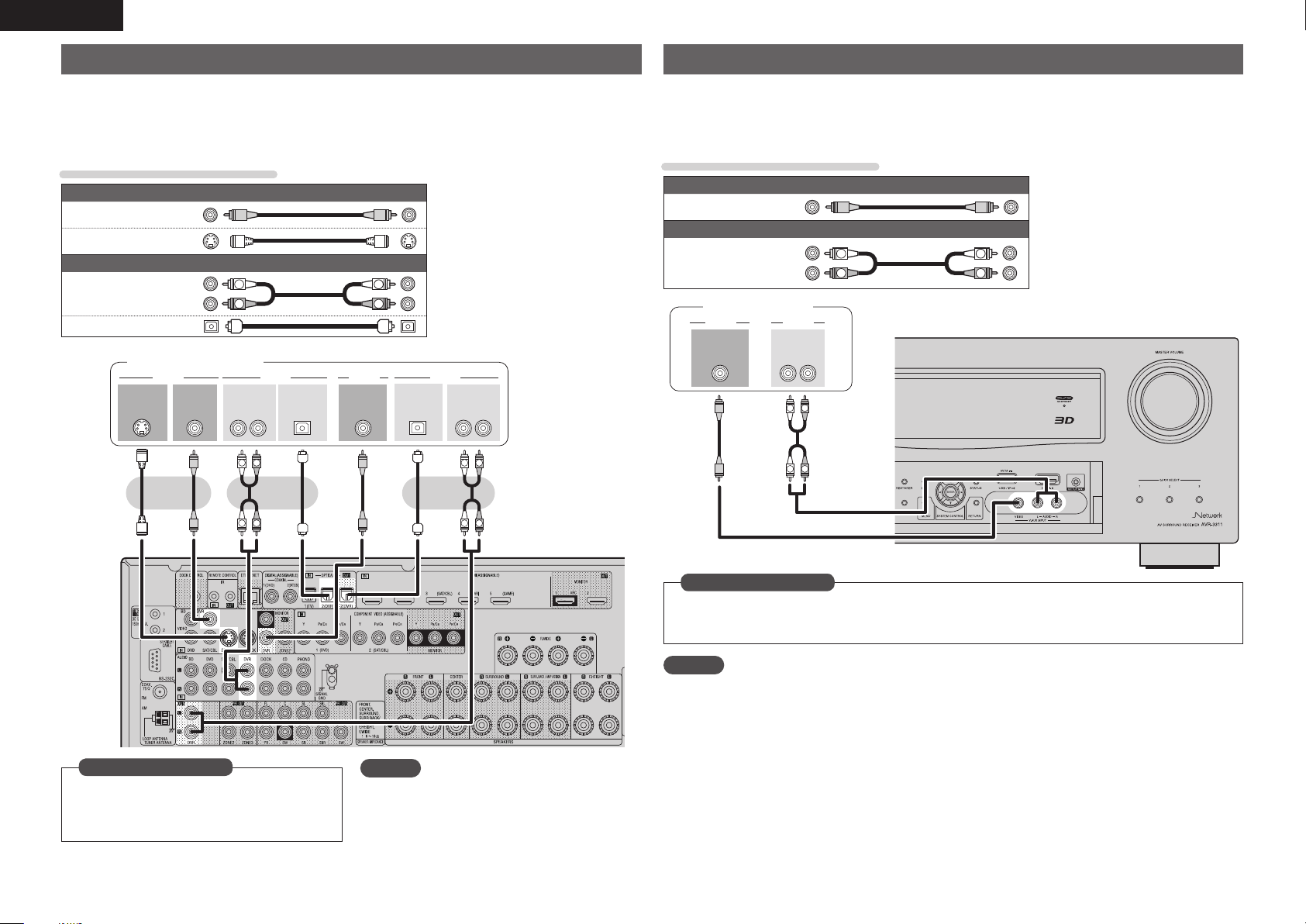
ENGLISH
Connecting a digital video recorder
• You can record video onto a Blu-ray Disc or DVD.
• Select the connector to use and connect the device.
• When recording analog audio, use the analog connection.
• See “REC OUT mode” (vpage52) for operating instructions.
• For instructions on HDMI connections, see “Connecting an HDMI-compatible device” (vpage14).
Cables used for connections
Video cable (sold separately)
Video cable
S-Video cable
Audio cable
Optical cable
(Yellow)
Audio cable (sold separately)
(White)
(Red)
L
R
Digital video recorder
S-VIDEO VIDEO
OUT
VIDEO
OUT
OPTICAL
OUT
L
OUT
RL RL
R
IN
L
R
AUDIOAUDIO VIDEOVIDEO
OPTICAL
IN
AUDIOAUDIO
IN
R
L
Connecting a digital camcorder
• You can enjoy video and audio from a digital camcorder.
• You can enjoy games by connecting a game machine via the V.AUX input connector. In this case, select
the input source to “V.AUX”.
• For instructions on HDMI connections, see “Connecting an HDMI-compatible device” (vpage14).
Cables used for connections
Video cable (sold separately)
Video cable
Audio cable
Digital camcorder
VIDEO
OUT
(Yellow)
Audio cable (sold separately)
(White)
(Red)
AUDIOVIDEO
AUDIO
OUT
L
L
L
R
RL
R
R
L
R
R
L
in Set as Necessary
Set this to change the digital input connector or
component video input connector to which the
input source is assigned.
“Input Assign” (vpage64)
18
R
L
NOTE
To record video signals through this unit, use the
same type of video cable for connection between
this unit and the player as used for connection
between this unit and the recorder.
in Set as Necessary
Set this to change the digital input connector or component video input connector to which the input
source is assigned.
“Input Assign” (vpage64)
NOTE
When a non-standard video signal from a game machine or some other source is input, the video conversion
function might not operate. In this case, use the monitor output of the same connector as the input.
Page 23
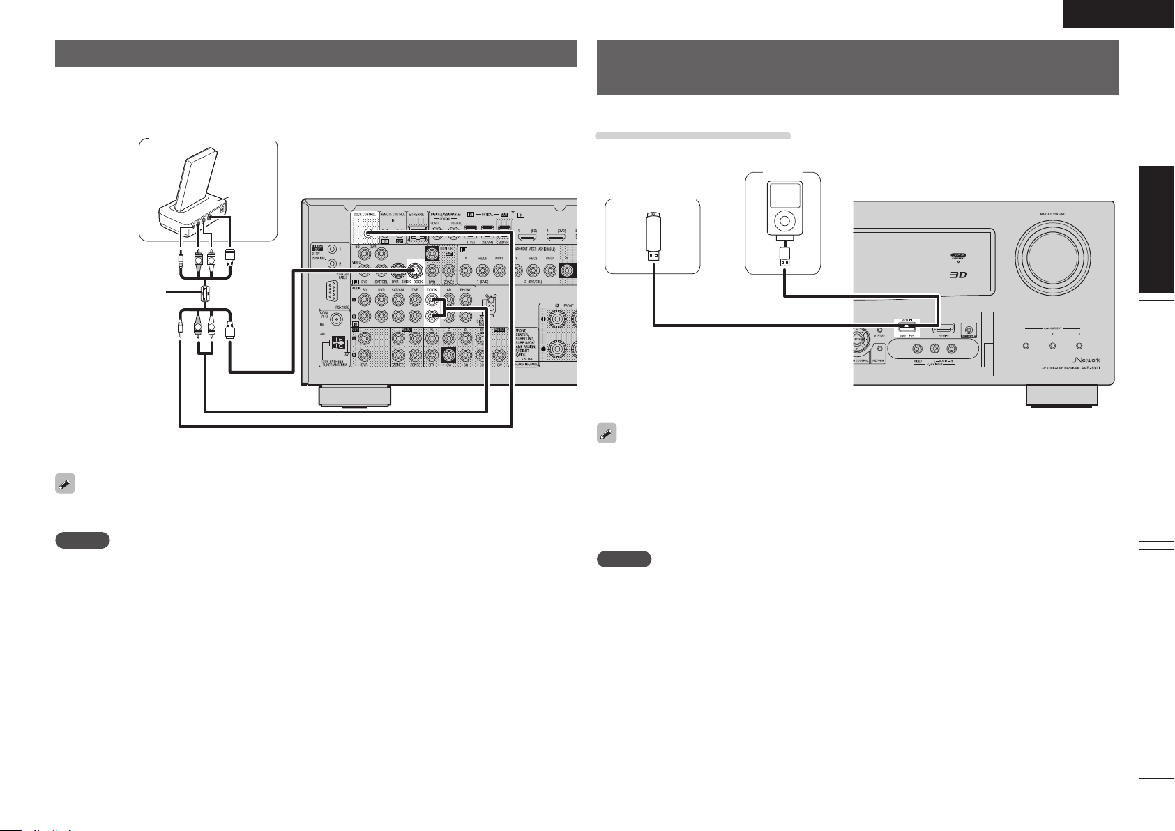
ENGLISH
Connecting a control dock for iPod
• Connect a control dock for iPod to the unit to enjoy video and music stored on an iPod.
• For a control dock for iPod, use ASD-1R and ASD-11R made by DENON (sold separately).
• For instructions on the control dock for iPod settings, refer to the control dock for iPod’s operating
instructions.
Control dock for iPod
ASD-11R
R
L
Use the AV/Control
Cable supplied with
the DENON control
dock for iPod.
You can also connect the iPod you are using directly to the USB port of this unit (vpage19 “Connecting
an iPod or USB memory device to the USB port”).
NOTE
When connecting an iPhone to this unit, keep the iPhone at least 20 cm away from this unit. If the iPhone is
kept closer to this unit and a telephone call is received by the iPhone, noise may be output from this device.
R
L
Connecting an iPod or USB memory device to the USB
port
You can enjoy music stored on an iPod or USB memory device.
Cables used for connections
To connect an iPod to this unit, use the USB cable supplied with the iPod.
iPod
USB memory
device
or
• When you want to playback a video file stored on an iPod, use a DENON control dock for iPod (ASD-1R
and ASD-11R, sold separately) (vpage19 “Connecting a control dock for iPod”).
• With iPods, playback is possible with iPhone, iPod touch, classic and nano released from the 5th-generation
of iPods. For details, check the DENON web site or page 27.
• DENON does not guarantee that all USB memory devices will operate or receive power. When using
a portable USB connection type HDD of the kind to which an AC adapter can be connected to supply
power, use the AC adapter.
NOTE
• USB memory devices will not work via a USB hub.
• Do not use an extension cable when connecting a USB memory device. This may cause radio interference
with other devices.
Simple version Advanced version InformationBasic version
19
Page 24
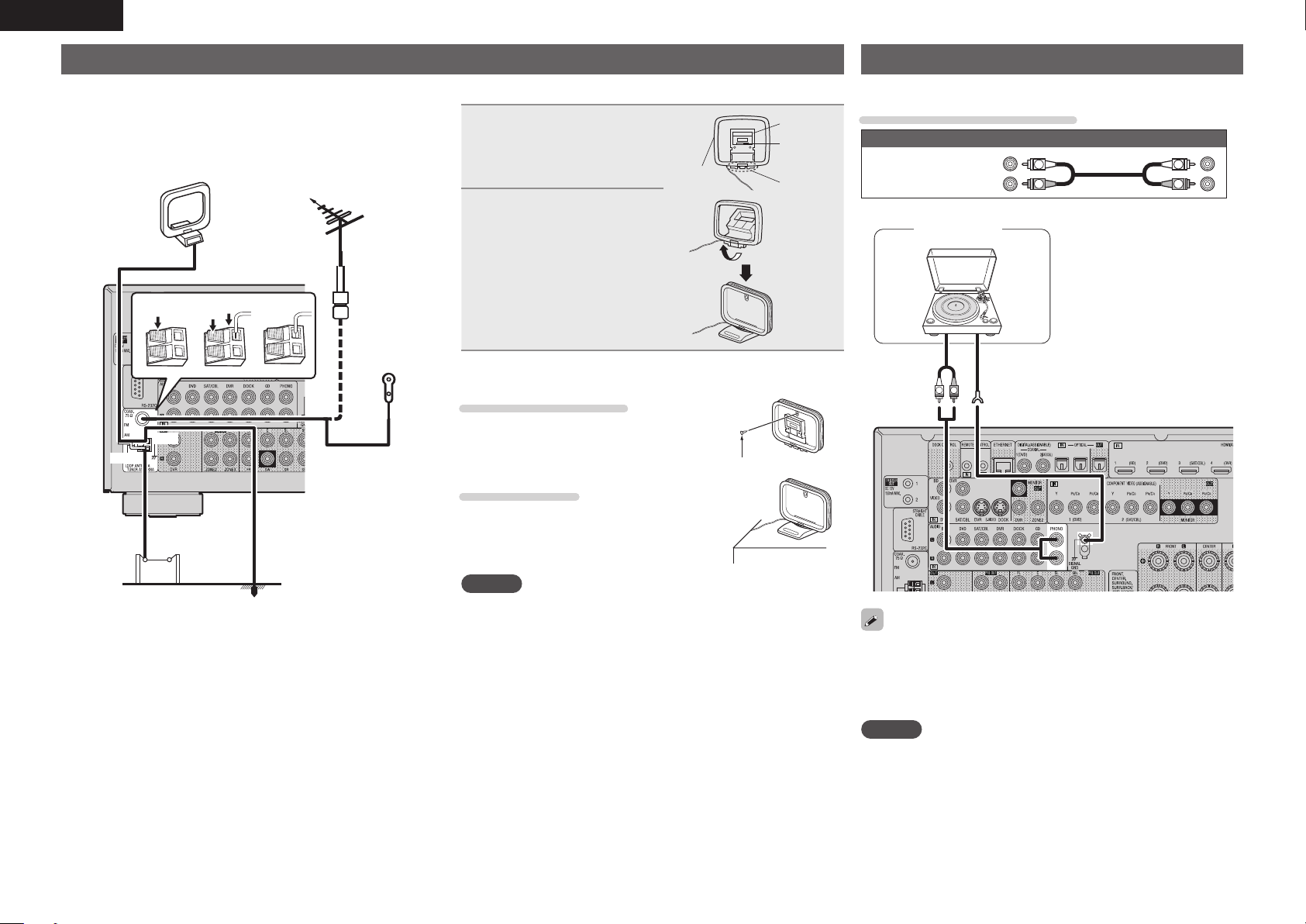
ENGLISH
Connecting an antenna
• Connect the FM antenna or AM loop antenna supplied with the unit
to enjoy listening to radio broadcasts.
• After connecting the antenna and receiving a broadcast signal
(vpage28 “Listening to FM/AM broadcasts”), fix the antenna with
tape in a position where the noise level becomes minimal.
AM loop antenna (supplied)
Direction of broadcasting station
FM outdoor
antenna
75 Ω coaxial
w eq
Black
White
cable
FM indoor
antenna
(supplied)
n AM loop antenna assembly
Put the stand section
1
through the bottom of the
loop antenna from the
rear and bend it forward.
Loop
antenna
Insert the projecting part
2
into the square hole in
the stand.
n Using the AM loop antenna
Suspending on a wall
Suspend directly on a wall without assembling.
Standing alone
Use the procedure shown left to assemble.
Stand
Square
hole
Projecting
part
Nail, tack, etc.
Connecting a record player
You can enjoy playing records.
Cables used for connections
Audio cable (sold separately)
Audio cable
(MM cartridge)
AUDIO
OUT
(White)
(Red)
Turntable
R
L
GND
L
R
L
R
20
AM outdoor
antenna
Ground
NOTE
• Do not connect two FM antennas simultaneously.
• Even if an external AM antenna is used, do not disconnect the AM
loop antenna.
• Make sure the AM loop antenna lead terminals do not touch metal
parts of the panel.
• If the signal has noise interference, connect the ground terminal
(GND) to reduce noise.
• If you are unable to receive a good broadcast signal, we recommend
installing an outdoor antenna. For details, inquire at the retail store
where you purchased the unit.
• This unit is compatible with record players with an MM cartridge.
When you connect to a record player with an MC cartridge, use a
commercially available MC head amp or a step-up transformer.
• When you increase the volume without connecting the record
player, there may be “booming” noise from the speakers.
NOTE
The SIGNAL GND terminal of this unit is not a safety ground
connection. Connect it to reduce noise when noise is excessive.
Note that depending on the record player, connecting the ground line
may have the reverse effect of increasing noise. In this case, it is not
necessary to connect the ground line.
Page 25
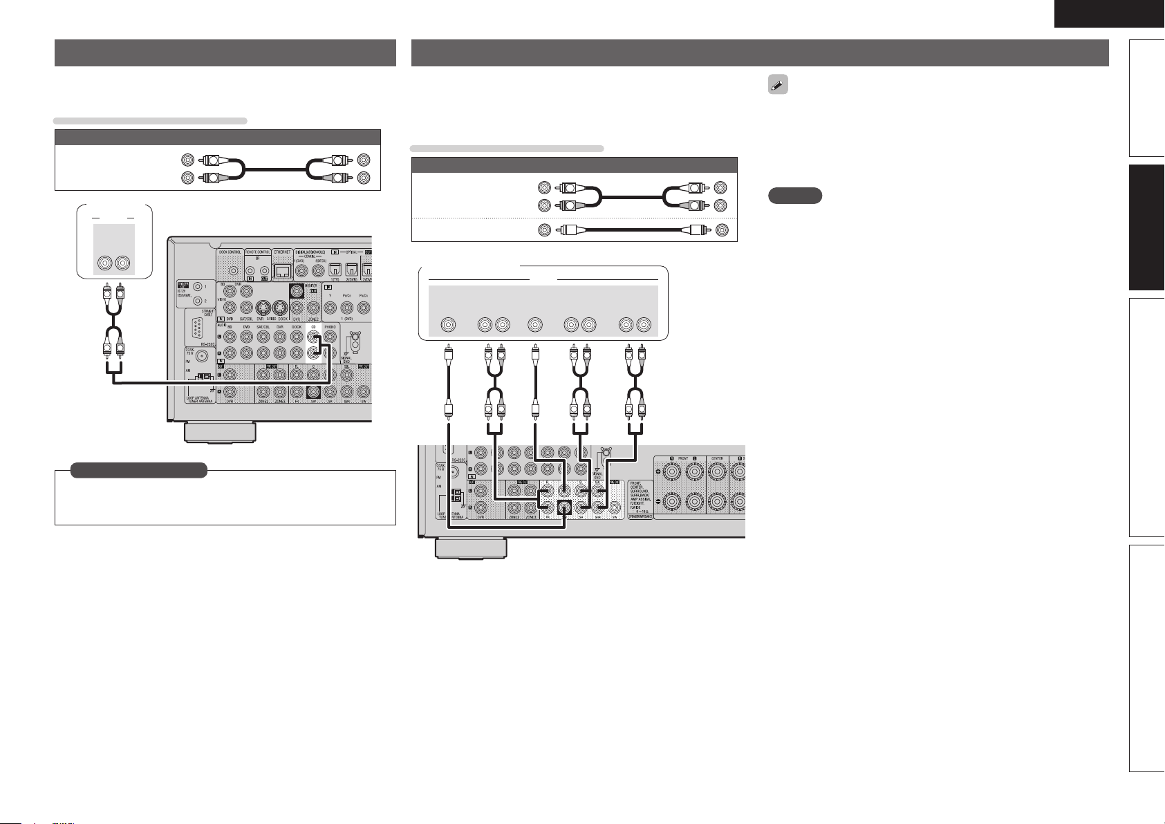
ENGLISH
Connecting a CD player
• You can enjoy CD sound.
• Select the connector to use and connect the device.
Cables used for connections
Audio cable (sold separately)
Audio cable
CD player
AUDIO
AUDIO
L
L
OUT
(White)
(Red)
RL
R
R
L
R
Connecting a external power amplifier
Simple version Advanced version InformationBasic version
• You can use this unit as a pre-amp by connecting a commercially
available power amp to the PRE OUT connector. Adding a power amp
to each of the channels provides an even greater sound presence.
• Select the terminal to use and connect the device.
• When using just one surround back speaker, connect it to the left
channel (L) terminal.
• Use the volume control on the subwoofer to control subwoofer
L
R
Audio cable
Audio cable
Audio cable (sold separately)
(White)
(Red)
L
R
L
R
Cables used for connections
volume.
• If the subwoofer volume sounds low, use the volume control
provided on the subwoofer to adjust the volume.
NOTE
• When speakers have been connected to PRE OUT terminals, do not
connect the speakers to the speaker terminals.
• The output channels for the PRE OUT connector change to SBL and
Power amplifier
SUB-
WOOFER
FRONT
L
L
RL
R
R
AUDIO
CENTER SURROUND
SURROUND
L
L
BACK
RL
R
R
RL
R
L
R
L
SBR in the “Amp Assign” (vpage75) settings in the menu.
in Set as Necessary
Set this to change the digital input connector to which the input
source is assigned.
“Input Assign” (vpage64)
.
21
Page 26
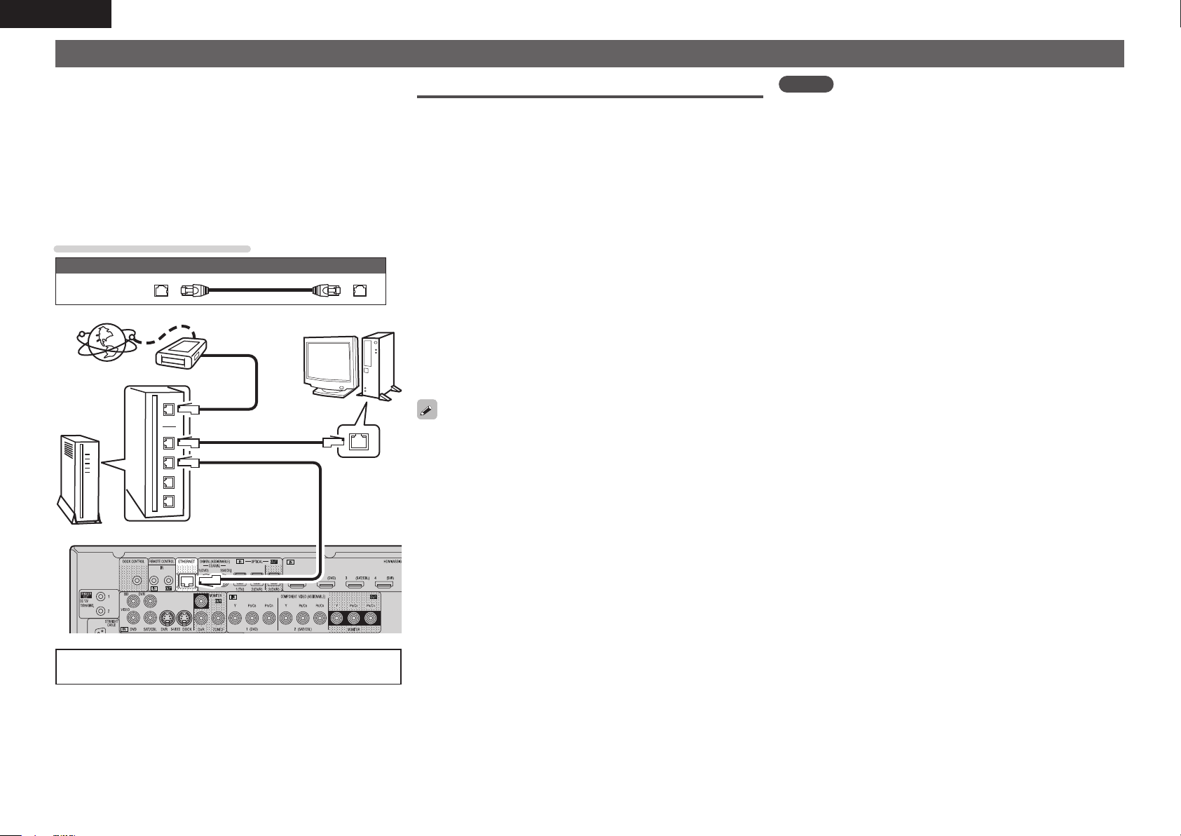
ENGLISH
Connecting to a home network (LAN)
• This unit lets you play via your home network (LAN) music files
stored on a computer and music content such as that from Internet
radio.
You can also operate this unit from a computer using the Web
control function.
• You can update by downloading the latest firmware from the
DENON website.
For more information, on the menu, select “Firmware Update”
(vpage84).
• See “Network Setup” on the menu (vpage79) for more information
on network setting.
Cables used for connections
Cable (sold separately)
Ethernet
cable
Computer
Modem
Internet
Required system
n Broadband internet connection
n Modem
Device that connects to the broadband circuit and conducts
communications on the Internet.
A type that is integrated with a router is also available.
n Router
When using this unit, we recommend you use a router equipped
with the following functions:
• Built-in DHCP server
This function automatically assigns IP addresses on the LAN.
• Built-in 100BASE-TX switch
When connecting multiple devices, we recommend a switching
hub with a speed of 100 Mbps or greater.
n Ethernet cable (CAT-5 or greater recommended)
• Use only shielded STP or ScTP LAN cable which is available at
retailer.
• Some flat type Ethernet cables are easily affected by noise.
We recommend using a normal type cable.
NOTE
• A contract with an ISP is required to connect to the Internet.
No additional contract is needed if you already have a broadband
connection to the Internet.
• The types of routers that can be used depend on the ISP. Contact an
ISP or a computer shop for details.
• DENON assumes no responsibility whatsoever for any
communication errors or troubles resulting from customer’s network
environment or connected devices.
• This unit is not compatible with PPPoE. A PPPoE-compatible router
is required if you have a contract for a type of line set by PPPoE.
• Do not connect an ETHERNET connector directly to the LAN port/
Ethernet connector on your computer.
To WAN side
To LAN port
To LAN port
Router
For connections to the Internet, contact an ISP (Internet
Service Provider) or a computer shop.
LAN port/
Ethernet
connector
22
• If you have an Internet provider contract for a line on which network
settings are made manually, make the settings at “Network Setup”
(vpage79).
• With this unit, it is possible to use the DHCP and Auto IP functions
to make the network settings automatically.
• When using this unit with the broadband router’s DHCP function
enabled, this unit automatically performs the IP address setting and
other settings.
When using this unit connected to a network with no DHCP
function, make the settings for the IP address, etc., at “Network
Setup” (vpage79).
• When setting manually, check the setting contents with the network
administrator.
Page 27
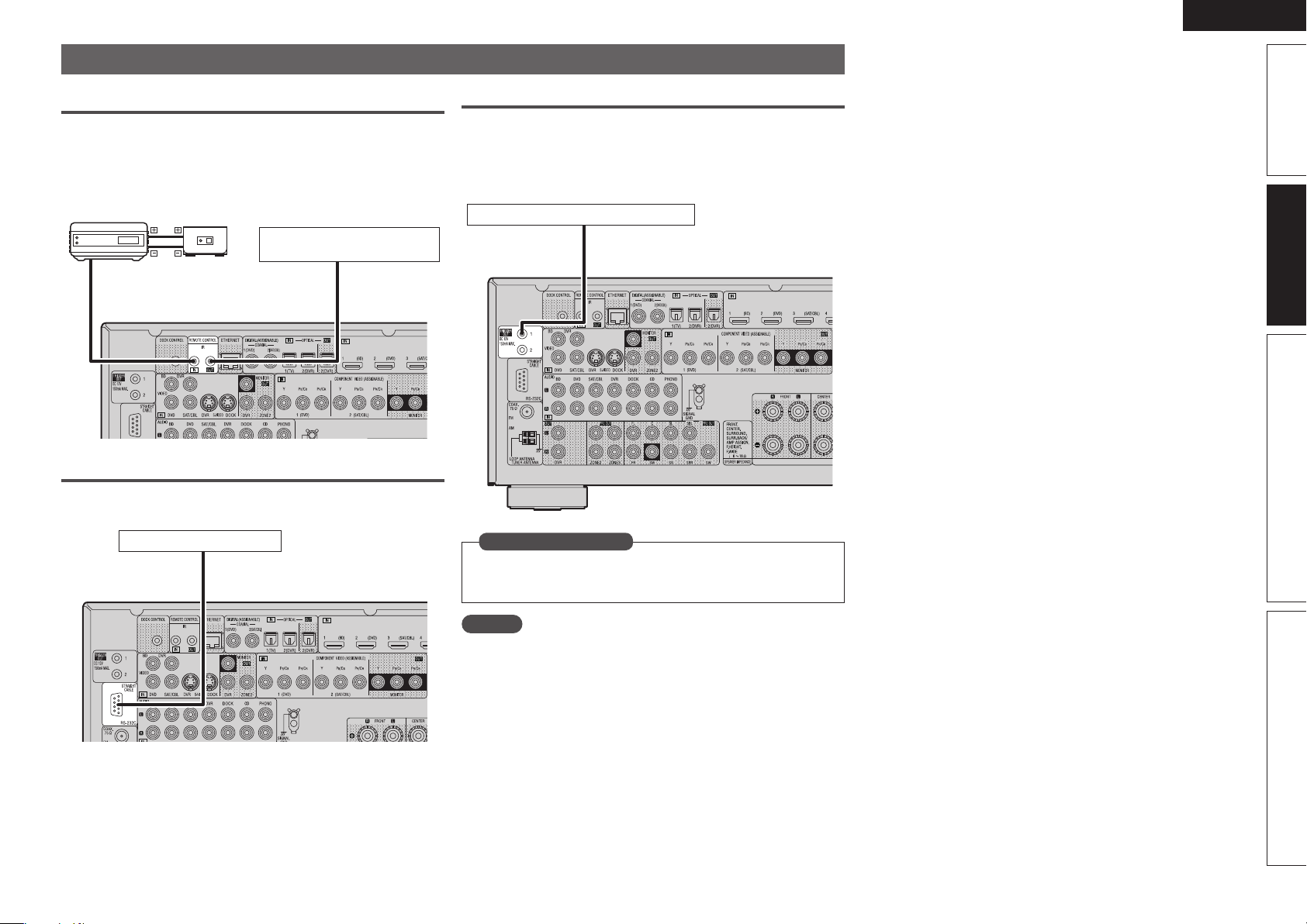
ENGLISH
Connecting an external control device
REMOTE CONTROL jacks
If this unit is installed in a location that is out of range of the signal
from the remote control unit, you can still operate the unit and the
devices connected to it by using a commercially available IR receiver.
You can also use it to remotely control ZONE2, ZONE3 (another room).
Infrared
retransmitter
AUX
OUT
Input
RS-232C connector
When you connect an external control device, you can control this unit
with the external control device.
Infrared
sensor
Output
Device equipped with a
REMOTE CONTROL IN jack
Simple version Advanced version InformationBasic version
TRIGGER OUT jacks
When a device with TRIGGER IN jack is connected, the connected
device’s power on/standby can be controlled through linked operation
to this unit.
The TRIGGER OUT jack outputs a maximum 12 V/150 mA electrical
signal.
12 V/150 mA trigger-compatible device
External serial controller
Perform the operation below beforehand.
q Turn on the power of this unit.
w Turn off the power of this unit from the external controller.
e Check that the unit is in the standby mode.
in Set as Necessary
Set to change the conditions for linked operation via the TRIGGER
OUT 1 or 2 jack.
“Trigger Out 1” or “Trigger Out 2” (vpage83)
NOTE
If the permissible trigger input level for the connected device is larger
than 12V/150mA, or has shorted, the TRIGGER OUT jack cannot be
used.
In this case, turn off the power to the unit, and disconnect it.
23
Page 28

ENGLISH
Playback (Basic operation)
n Selecting the input source (vpage24)
n Adjusting the master volume (vpage24)
n Turning off the sound temporarily (vpage25)
n Playing a Blu-ray Disc player/DVD player
(vpage25)
n Playing a CD player (vpage25)
n Playing an iPod® (vpage25)
n Tuning in radio stations (vpage28)
n Playing a network audio (vpage30)
n Playing a USB memory device (vpage38)
Selecting a listening mode (Surround mode)
(vpage40)
Playback (Advanced operation) (vpage50)
Important information
Before starting playback, make the connections between the different
components and the settings on the receiver.
NOTE
Also refer to the operating instructions of the connected components
when playing them.
Selecting the input source
Press the input source select button
(NET/USB, iPod, DVD, BD, TUNER,
DOCK, SAT/CBL, GAME, V.AUX,
PHONO, CD, DVR, TV) to be played
back.
The desired input source can be selected
directly.
• When iPod PLAY is pressed, the input source of this unit is
switched to “DOCK” or “NET/USB” and the connected iPod is
automatically played (vpage28 “iPod play function”).
You can also use the following operation to select an input
source.
n Using the “Source Select” menu
q Press SOURCE SELECT.
Display the “Source Select” menu.
q
Sou rce Sele ct :Flic kr
Rec ent Sour ce
w
e
q Input Source
The name of the highlighted input source is displayed.
w Recently used sources
The recently used input sources (up to five) are displayed.
e Icons for the input sources in the different categories are
displayed.
w Use uio p to select the input source,
then press ENTER.
The input source is set and the source
selection menu is turned off.
The currently selected input
source is highlighted.
Sel ect
Ent er
ENT ER
• When using with an iPod connected directly to the USB port of this
unit, select “ (USB/iPod)” for the input source.
• Input sources that are not going to be used can be set ahead of time.
Make this setting at “Source Delete” (vpage82).
• To turn off the source selection menu without selecting an input
source, press SOURCE SELECT again.
n Using the knob on the main unit
Turn SOURCE SELECT.
• If “Rec Select” or “Tuning Preset”
mode is selected for the input
source, press SOURCE before
turning SOURCE SELECT.
• Turning SOURCE SELECT switches
the input source, as shown below.
BD DVD TV SAT/CBL GAMEDVR V.AUX
CD PHONO TUNER NET/USB DOCK
Adjusting the master volume
Use VOL df to adjust the volume.
n When the “Volume Display” setting
(vpage82) is “Relative”
GAdjustable rangeH
– – –
–80.5dB – 18.0dB
n When the “Volume Display” setting (vpage82) is
“Absolute”
GAdjustable rangeH
• The variable range differs according to the input signal and channel
level setting.
You can also operate via the main unit.
In this case, perform the following
operations.
Turn MASTER VOLUME to adjust the
volume.
0.0 – 99.0
24
Page 29
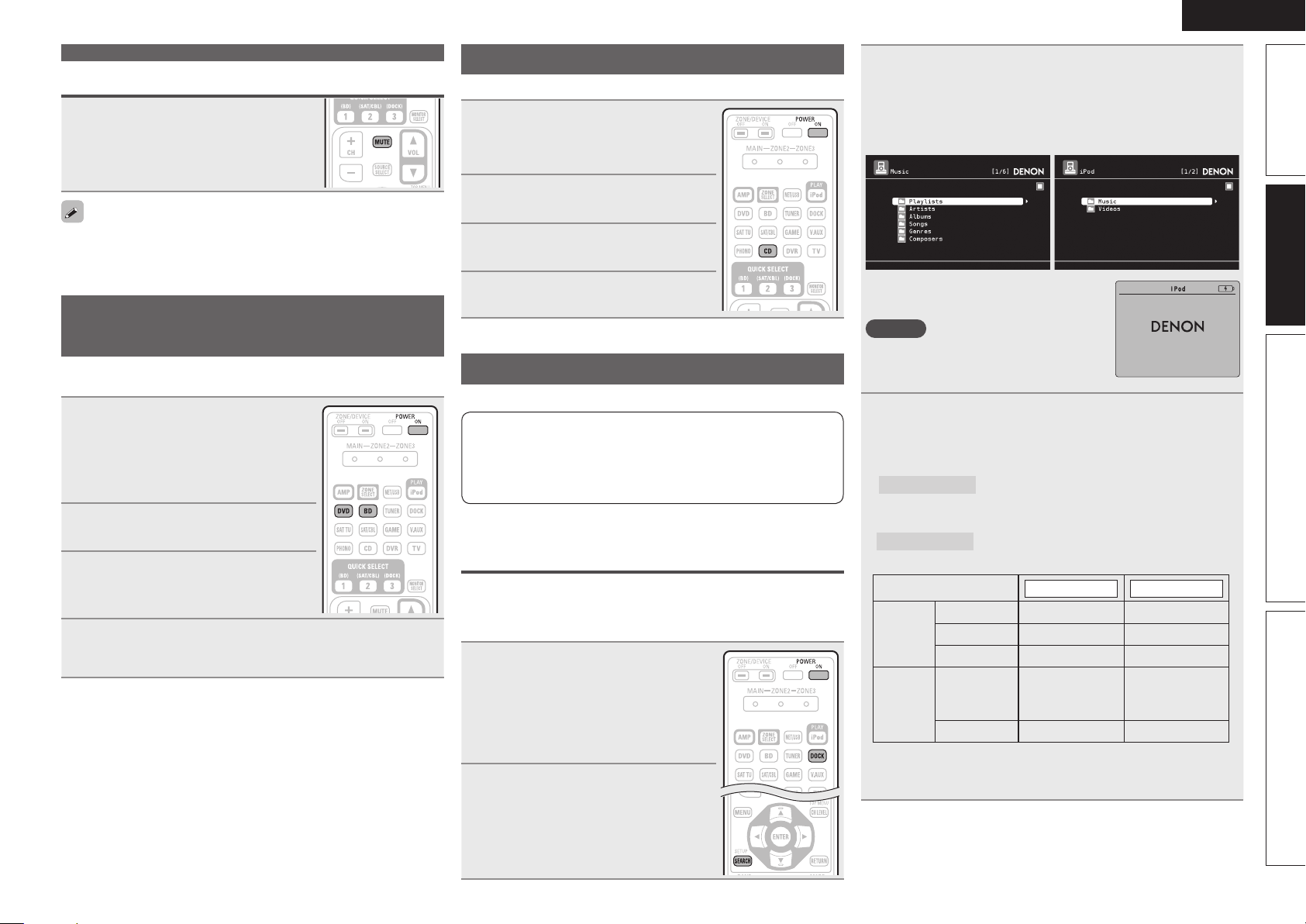
ENGLISH
Important information
Turning off the sound temporarily
Press MUTE.
• The sound is reduced to the level set at “Mute Level” (vpage82).
• To cancel, press MUTE again. Muting can also be canceled by
adjusting the master volume.
Playing a Blu-ray Disc player/DVD
player
The following describes the procedure for playing Blu-ray Disc player/
DVD player.
Prepare for playback.
q Turn on the power of the TV,
1
2
3
4
subwoofer and player.
w Change the TV input to the input of
this unit.
e Load the disc in the player.
Press POWER ON to turn on
power to the unit.
Press BD or DVD to switch an
input source for a player used for
playback.
Play the component connected to this unit.
Make the necessary settings on the player (language setting,
subtitles setting, etc.) beforehand.
Playing a CD player
The following describes the procedure for playing CD player.
Prepare for playback.
q Turn on the power of the subwoofer
1
2
3
4
There are two methods for iPod playback.
q
DENON control dock for iPod usable on this unit
• ASD-1R / ASD-11R
1
2
and player.
w Load the disc in the player.
Press POWER ON to turn on
power to the unit.
Press CD to switch the input
source to the CD player.
Play the component connected to
this unit.
Playing an iPod
q Use a DENON control dock for iPod to play back.
You can play back both video, photo and audio.
w Connect an iPod directly to the USB port to play back
(vpage27).
You can play back audio only.
®
Use a DENON control dock for iPod to
play back
n Listening to music on an iPod
Prepare for playback.
q Connect the DENON control dock
for iPod to this unit (vpage19
“Connecting a control dock for
iPod”).
w Set the iPod
control dock for iPod.
Press POWER ON to turn on
power to the unit.
®
in the DENON
®
Press DOCK to switch the input source to “DOCK”.
3
• If ”Browse mode” is selected in step 4, the following screen is
displayed on a TV screen, depending on the connected control
dock for iPod.
(When using an ASD-1R) (When using an ASD-11R)
• In ”Browse mode”, the iPod display is as
shown at right.
NOTE
If the connections screen is not displayed,
the iPod may not be properly connected.
Reconnect it.
Press SEARCH and hold it down for 2 seconds or
4
more to select the display mode.
• There are two modes for displaying the contents recorded on the
iPod.
Browse mode
• English letters, numbers and certain symbols are displayed.
Incompatible characters are displayed as “.” (period).
Remote mode
• “Remote iPod” is displayed on the display of this unit.
Display mode
Playable
files
Active
buttons
z1 When using an ASD-11R DENON control dock for iPod.
z2 Video may not be output, depending on the combination of
ASD-1R or ASD-11R DENON control dock for iPod and iPod.
Display iPod information on the TV screen.
Display iPod information on the iPod screen.
Browse mode Remote mode
Music file
Photo file
Video file
Remote
control unit
(This unit)
®
iPod
P P
z1
P
P P
OK to disconnect.
z2
P
z2
P
P
Simple version Advanced version InformationBasic version
25
Page 30
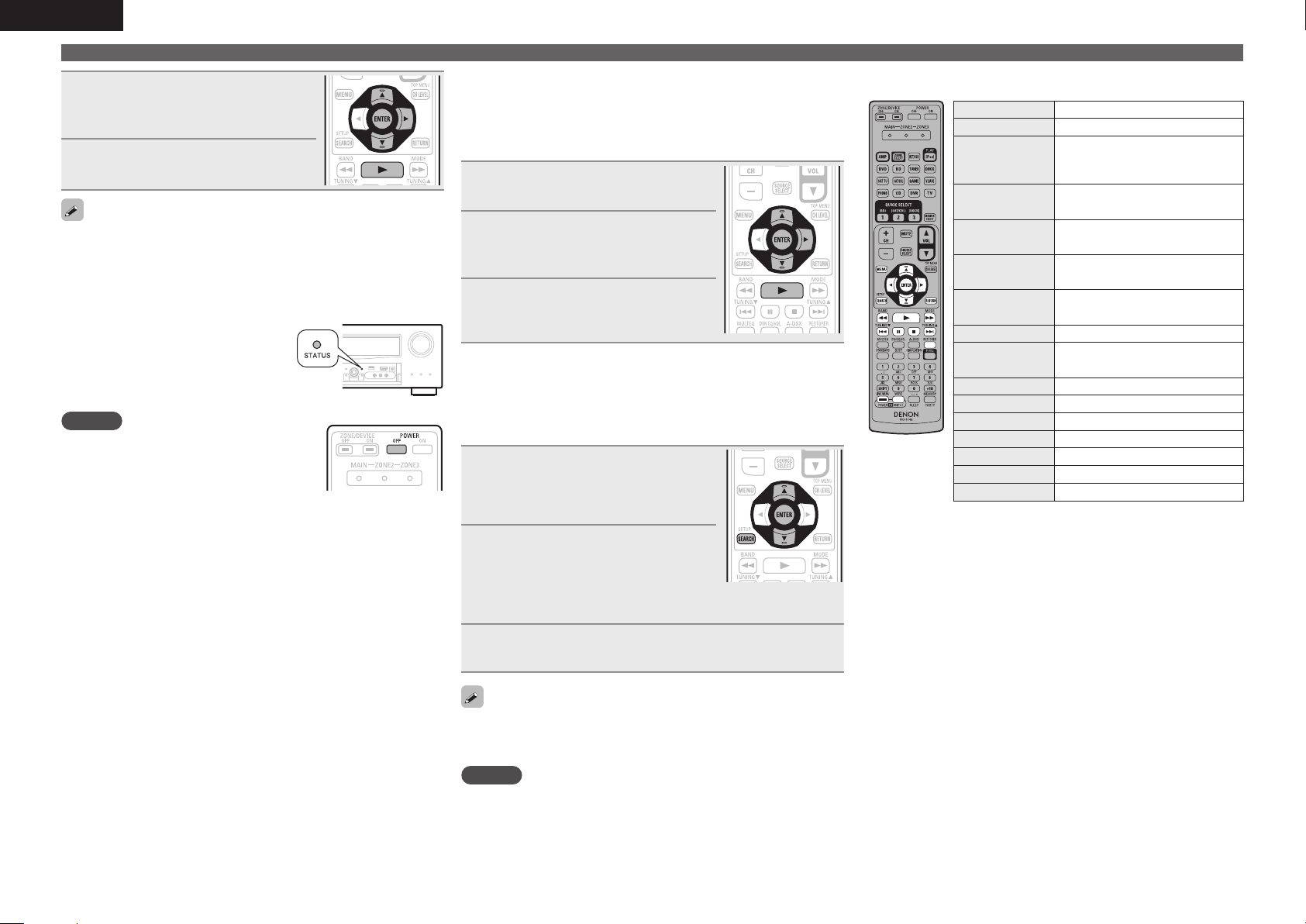
ENGLISH
Playing an iPod
®
Use ui to select the item, then
5
press ENTER or p to select the
le to be played.
Press ENTER, p or 1.
6
Playback starts.
• You can specify the duration of the on-screen display to be displayed
(default: 30 sec) at menu “iPod” (vpage83). Press uio p to
return to the original screen.
• To play back compressed audio with extended bass or treble
reproduction, we recommend playback in RESTORER mode
(vpage73). The default setting is “Mode3”.
• In Browse mode, press
playback to check the title name, artist
name, and album name.
NOTE
• Press POWER OFF and set this unit’s power
to the standby mode before disconnecting
the iPod. Also switch the input source to
“DOCK” before disconnecting the iPod.
• Depending on the type of iPod and the software version, some
functions may not operate.
• Note that DENON will accept no responsibility whatsoever for any
problems arising with the data on an iPod when using this unit in
conjunction with the iPod.
STATUS during
n Viewing videos on an iPod® in the Browse
mode
When an iPod equipped with a video function is connected to a
DENON ASD-11R control dock for iPod, image files can be played
in the Browse mode.
Use ui to select “Videos”, then
1
press ENTER or p.
Use ui to select the search item
2
or folder, then press ENTER or
p.
Use ui to select the video le,
3
then press ENTER, p or 1.
Playback starts.
n Viewing photos and videos on an iPod® in the
Remote mode
This unit can play back on a TV screen photos and data stored on an
iPod equipped with a slide show or video function.
Press and hold SEARCH to set the
1
Remote mode.
“Remote iPod” or “Dock Remote“is
displayed on the display of this unit.
Watching the iPod’s screen,
2
use ui to select “Photos” or
“Videos”.
• Depending on the iPod model, it may be necessary to operate the
iPod unit directly.
n iPod operation
Operation buttons Function
(Press and release)
(Press and hold)
(Press and release)
(Press and hold)
(Press and hold)
8 9
RESTORER RESTORER
TV POWER TV power on/standby (Default : SONY)
• Repeat playback (vpage67 “Repeat”)
• Shuffling playback (vpage67 “Shuffle”)
z When the menu screen is displayed, press
SEARCH, then press o (previous page) or p (next
page).
To cancel, press ui or SEARCH.
MENU Amp menu
Cursor operation /
uio p
ENTER
ENTER
SEARCH
SEARCH
RETURN Return
6 7
1
3
2
TV INPUT Switch TV input (Default : SONY)
Auto search (cue, ui) /
Manual search (Press and hold, ui)
Enter / Pause
Stop
Page search mode
Browse / Remote mode switching
Manual search
(fast-reverse/fast-forward)
Playback / Pause
Auto search (cue)
Pause
z
Stop
26
Press ENTER until the image you want to view is
3
displayed.
“TV Out” at the iPod’s “Slide show Settings” or “Video Settings”
must be set to “On” in order to display the iPod’s photo data or videos
on the monitor. For details, see the iPod’s operating instructions.
NOTE
Video may not be output, depending on the combination of ASD-1R or
ASD-11R and iPod.
Page 31

ENGLISH
w
Connect an iPod directly to the USB port
to play back
You can use the USB cable provided with the iPod® to connect the
iPod with the unit’s USB port and enjoy music stored on the iPod.
• This unit supports audio playback from the iPod (fifth generation
or later), iPod nano, iPod classic, iPod touch and iPhone (it is not
compatible with iPod shuffle).
Connect the iPod® to the USB port (vpage 19
“Connecting an iPod or USB memory device to the
1
USB port”).
Press POWER ON to turn on
2
power to the unit.
Press NET/USB to switch the
3
input source to “NET/USB”.
DENON:[ AVR-3311CI]
Favorit e
Interne t Radio
Media S erver
iPod
Flickr
Last.fm
Napster
Use ui to select “iPod”, then
4
press ENTER or p.
iPod
Playlis ts
Artists
Albums
Songs
Podcast s
Genres
Compose rs
NOTE
If the connections screen is not displayed, the iPod may not be
properly connected. Reconnect it.
[1/8]
[1/8]
SEARCH
Search
Press SEARCH and hold it down for 2 seconds or
5
more to select the display mode.
• There are two modes for displaying the contents recorded on the
iPod.
Browse mode
• English letters, numbers and certain symbols are displayed.
Incompatible characters are displayed as “.” (period).
Remote mode
• “Remote iPod” is displayed on the display of this unit.
• The Remote mode is not supported on fifth generation iPod or
first generation iPod nano.
Display mode
Playable
files
Active
buttons
zOnly the sound is played.
Display iPod information on the TV screen.
Display iPod information on the iPod screen.
Browse mode Remote mode
Music file
Video file
Remote
control unit
(This unit)
®
iPod
P P
P P
z
P
Use ui to select the item, then press ENTER or p
6
to select the le to be played.
Press ENTER, p or 1.
7
Playback starts.
• You can specify the duration of the on-screen display to be displayed
(default: 30 sec) at menu “iPod” (vpage83). Press uio p to
return to the original screen.
• To play back compressed audio with extended bass or treble
reproduction, we recommend playback in RESTORER mode
(vpage73). The default setting is “Mode3”.
• In Browse mode, press
playback to check the title name, artist
name, and album name.
NOTE
• Depending on the type of iPod and the software version, some
functions may not operate.
• Note that DENON will accept no responsibility whatsoever for any
problems arising with the data on an iPod when using this unit in
conjunction with the iPod.
STATUS during
n iPod operation
Operation buttons Function
(Press and release)
(Press and hold)
(Press and release)
(Press and hold)
(Press and hold)
8 9
RESTORER RESTORER
TV POWER TV power on/standby (Default : SONY)
• Repeat playback (vpage68 “Repeat”)
• Random playback (vpage68 “Random”)
z1 When the menu screen is displayed, press
z2 When the menu screen is displayed, press
Playing an iPod
MENU Amp menu
Cursor operation /
uio p
ENTER
ENTER
SEARCH
SEARCH
RETURN Return
6 7
1
3
2
TV INPUT Switch TV input (Default : SONY)
Auto search (cue, ui) /
Manual search (Press and hold, ui)
Enter / Pause
Stop
Page search
z1
/ Character search
Browse / Remote mode switching
Manual search
(fast-reverse/fast-forward)
Playback / Pause
Auto search (cue)
Pause
Stop
®
z2
SEARCH, then press o (previous page) or p
(next page).
To cancel, press ui or SEARCH twice.
SEARCH twice, then press o p to select the
first letter you want to search mode.
• If it is not possible to search the list, “unsorted
list.” is displayed.
To cancel, press ui or SEARCH.
If the list is not in alphabetical order, you may
not be able to perform a character search.
27
Simple version Advanced version InformationBasic version
Page 32

ENGLISH
Playing an iPod
®
iPod play function
If iPod PLAY is pressed when power of this unit is on standby and a
control dock for iPod or an iPod (USB) is connected, the iPod starts
playback.
Press iPod PLAY.
• Power of this unit is turned on.
• This unit’s input source switches to
“DOCK” or “NET/USB”.
• iPod playback starts.
If iPod PLAY on the main unit is pressed, the
same function as with the remote control unit
can be obtained.
NOTE
• iPod play function does not function if a control dock for iPod
(“DOCK”) or an iPod (“NET/USB”) is not connected.
• If both a control dock for iPod (“DOCK”) and an iPod (“NET/USB”)
are connected, playback with control dock for iPod (“DOCK”) takes
priority.
Tuning in radio stations
Listening to FM/AM broadcasts
Press TUNER to switch the input
1
source to “TUNER”.
Press BAND to select “FM” or
2
“AM”.
FM
When listening to an FM broadcast.
AM
When listening to an AM broadcast.
TUNER
AUTO
Now Pla ying
Tuning
Preset
FM 87. 50MHz
Band
MEMORY
Memory
SEARCH
Mode
Search
CH A1
/
CH+/
-
Tune in the desired broadcast station.
3
q To tune in automatically (Auto tuning)
Press MODE to light the “AUTO” indicator on the display, then
use TUNING d or TUNING f to select the station you want to
hear.
w To tune in manually (Manual tuning)
Press MODE to turn off the display’s “AUTO” indicator, then use
TUNING d or TUNING f to select the station you want to hear.
• If the desired station cannot be tuned in with auto tuning, tune it in
manually.
• When tuning in stations manually, press and hold TUNING d or
TUNING f to change frequencies continuously.
• You can specify the duration of the on-screen display to be displayed
(default: 30 sec) at menu “TUNER” (vpage83). Press uio p to
return to the original screen.
n Presetting radio stations (Manual preset)
Your favorite broadcast stations can be preset so that you can tune
them in easily. Up to 56 stations can be preset.
• Stations can be preset automatically at “Auto Preset”
(vpage64). If “Auto Preset” is performed after performing “Manual
Preset”, the “Manual Preset” settings will be overwritten.
Tune in the broadcast station you
1
want to preset.
Press MEMORY.
2
Press SHIFT to select the block
3
(A to G) in which to preset the
channel (1 to 8 per block), then
press CH +, CH – or 1 – 8 to select
the preset number.
Press MEMORY again to complete
4
the setting.
• To preset other stations, repeat steps 1 to
4.
Default settings
Block (A – G)
and
Channel (1 – 8)
A1 – A8
B1 – B8
C1 – C8 90.1 MHz
D1 – D8 90.1 MHz
E1 – E8 90.1 MHz
F1 – F8 90.1 MHz
G1 – G8 90.1 MHz
87.5 / 89.1 / 98.1 / 108.0 / 90.1 / 90.1 / 90.1 /
90.1 MHz
522 / 603 / 999 / 1404 / 1611 kHz,
90.1 / 90.1 / 90.1 MHz
Default Settings
28
Specify a name for the preset broadcast station
(Preset Name) (vpage64)
Page 33

ENGLISH
n Listening to preset stations
Press SHIFT to select the memory
1
block (A to G).
Press CH +, CH – or 1 – 8 to select
2
the desired preset channel.
You can also operate via the main unit.
In this case, perform the following
operations.
Press TUNING PRESET, then turn SOURCE
SELECT
to select the preset radio station.
n Direct frequency tuning
You can enter the receiving frequency directly to tune in.
Press SEARCH.
1
Input frequencies using the 0 – 9.
2
• If o is pressed, the immediately preceding
input is cancelled.
When setting is completed, press
3
ENTER.
The preset frequency is tuned in.
RDS (Radio Data System)
RDS (works only on the FM band) is a broadcasting service which
allows a station to send additional information along with the regular
radio program signal.
NOTE
The operations described as follows using
SEARCH will not function in areas in which
there are no RDS broadcasts.
n RDS search
Use this function to automatically tune to FM stations that provide
the RDS service.
Press TUNER to switch the input
1
source to “TUNER”.
Press SEARCH to select “RDS
2
SEARCH”.
TUNER
MHz
CH+/ -
Ban dTun ing
STE REO AU TO
Now Playi ng
Tuni ng
7
Mod e
Sea rch
SEAR CH
Program Category
: RDS Station
RDS
: Program Category
PTY
: Traffic Information
TP
FM
***.**
: Radio Text ON
RT
CH A
CH+/ - MEMO RY
PS Name
Jamp to album
A5 F M 90.1 0MHz
SEAR CH
Mode
Pre set Mem ory
68/9
Press CH + or CH –.
3
The search for RDS stations begins automatically.
• If no RDS stations are found with the above operation, all the
reception bands are searched.
• When a broadcast station is found, that station’s name appears on
the display.
• If no RDS station is found when all the frequencies have been
searched, “NO RDS” is displayed.
Tuning in radio stations
PTY (Program Type)
PTY identifies the type of RDS program.
The program types and their displays are as follows:
NEWS
AFFAIRS
INFO
SPORT
EDUCATE
DRAMA
CULTURE
SCIENCE
VARIED
POP M
ROCK M
EASY M
LIGHT M
CLASSICS
OTHER M
News
Current Affairs
Information
Sports
Education
Drama
Culture
Science
Varied
Pop Music
Rock Music
Easy Listening
Music
Light Classical
Serious Classical
Other Music
WEATHER
FINANCE
CHILDREN
SOCIAL
RELIGION
PHONE IN
TRAVEL
LEISURE
JAZZ
COUNTRY
NATION M
OLDIES
FOLK M
DOCUMENT
n PTY search
Use this function to find RDS stations broadcasting a designated
program type (PTY).
Press TUNER to switch the input
1
source to “TUNER”.
Press SEARCH to select “PTY
2
SEARCH”.
TUNER
NEWS
AFFAIRS
INFO
MHz
SPORT
Ban dTun ing
STE REO AU TO
Tuni ng
CH+/ -
SEAR CH
Now Playi ng
7
Mod e
Sea rch
Program Category
RDS
PTY
TP
FM
***.**
RT
CH A
CH+/ - MEMO RY
PS Name
Jamp to album
A5 F M 90.1 0MHz
SEAR CH
Mode
Pre set Mem ory
68/9
Watching the display, press ui to call out the
3
desired program type.
Weather
Finance
Children’s
program
Social Affairs
Religion
Phone In
Travel
Leisure
Jazz Music
Country Music
National Music
Oldies Music
Folk Music
Documentary
Simple version Advanced version InformationBasic version
29
Page 34

ENGLISH
Tuning in radio stations
Press CH + or CH –.
4
PTY search begins automatically.
• If there is no station broadcasting the designated program type
with the above operation, all the reception bands are searched.
• The station name is displayed on the display after searching stops.
• If no station broadcasting the designated program type is found
when all the frequencies have been searched, “NO PROGRAMME”
is displayed.
TP (Traffic Program)
TP identifies programs that carry traffic announcements.
This allows you to easily find out the latest traffic conditions in your
area before leaving home.
n TP search
Use this function to find RDS stations broadcasting traffic programs
(TP stations).
Press TUNER to switch the input
1
source to “TUNER”.
Press SEARCH to select “TP
2
SEARCH”.
TUNER
MHz
CH+/ -
Ban dTun ing
STE REO AU TO
Now Playi ng
Tuni ng
7
Mod e
Sea rch
SEAR CH
Program Category
: RDS Station
RDS
: Program Category
PTY
: Traffic Information
TP
FM
***.**
: Radio Text ON
RT
CH A
CH+/ - MEMO RY
PS Name
Jamp to album
A5 F M 90.1 0MHz
SEAR CH
Mode
Pre set Mem ory
68/9
Press CH + or CH –.
3
TP search begins automatically.
• If no TP station is found with the above operation, all the reception
bands are searched.
• The station name is displayed on the display after searching stops.
• If no other TP station is found when all the frequencies have been
searched, “NO PROGRAMME” is displayed.
RT (Radio Text)
RT allows RDS stations to send text messages that appear on the
display.
“RT” appears on the display when radio text data is received.
Press TUNER to switch the input
1
source to “TUNER”.
Press SEARCH to select “RT”.
2
TUNER
Program Category
: RDS Station
RDS
: Program Category
PTY
: Traffic Information
TP
FM
***.**
: Radio Text ON
RT
CH A
CH+/ - MEMO RY
PS Name
Jamp to album
A5 F M 90.1 0MHz
SEAR CH
Mode
Pre set Mem ory
68/9
• While receiving an RDS broadcast station, the text data broadcast
from the station is displayed.
• To turn the display off, press o p.
• If no text data is being broadcast, “NO TEXT DATA” is displayed.
n Tuner (FM/AM) operation
Operation buttons Function
TUNING df
TV POWER TV power on/standby (Default : SONY)
STE REO AU TO
Now Playi ng
MHz
Tuni ng
CH+/ -
7
SEAR CH
Mod e
Sea rch
Ban dTun ing
CH +, – Preset channel selection
MENU Amp menu
uio p
Cursor operation
ENTER Enter setting
SEARCH Direct frequency tuning / RDS search
RETURN Return
BAND FM/AM switching
MODE Switch search modes
Tuning (up/down)
0 – 9
Preset channel selection (1 – 8) /
Direct frequency tuning (0 – 9)
SHIFT Preset channel block selection
MEMORY Preset memory registration
TV INPUT Switch TV input (Default : SONY)
Playing a network audio
Follow this procedure to play Internet radio stations or music or still
picture (JPEG) files stored on a computer.
Important information
n About the internet radio function
• Internet radio refers to radio broadcasts distributed over the
Internet.
Internet radio stations from around the world can be received.
• This unit is equipped with the following Internet radio functions:
• Stations can be selected by genre and region.
• Up to 56 Internet radio stations can be preset.
• Internet radio stations in MP3 and WMA (Windows Media
Audio) format can be listened to.
• Your favorite radio stations can be registered by accessing an
exclusive DENON Internet radio URL from a Web browser on
a computer.
• The function is managed for individual users, so you must provide
your MAC or e-mail address.
Exclusive URL: http://www.radiodenon.com
• The radio station database service may be suspended without
notice.
• This unit’s Internet radio station list is created using a radio
station database service (vTuner). This database service provides
a list edited and created for this unit.
n Media player
This function lets you play music files and playlists (m3u, wpl)
stored on a computer (media server) connected to this unit via a
network.
With this unit’s network audio playback function, connection to the
server is possible using one of the technologies below.
• Windows Media Player Network Sharing Service
• Windows Media DRM10
Album art function
When a WMA (Windows Media Audio), MP3 or MPEG-4 AAC file
includes album art data, the album art can be displayed while the
music files are playing.
For music files in WMA (Windows Media Audio) format, the album art
is only played when using Windows Media Player ver. 11.
30
Page 35

ENGLISH
Slide show function
Still picture (JPEG) files stored in folders on a media server can be
played as slide shows. The duration each picture is displayed can be
set.
This unit plays back image (JPEG) files in the orientation in which they
are stored in the folder.
GCompatible formatsH
Internet radio Media server
WMA (Windows
Media Audio)
MP3 (MPEG-1 Audio
Layer-3)
WAV
MPEG-4 AAC
FLAC (Free Lossless
Audio Codec)
JPEG
A server or server software compatible with distribution in the
corresponding formats is required to play music files via a network.
z1 Media server
• This unit is compatible with MP3 ID3-Tag (Ver. 2) standard.
• This unit can show the artwork that was embedded by using
MP3 ID3-Tag Ver. 2.3 or 2.4.
• This unit is compatible with WMA META tags.
• WAV format Quantization bit rate: 16 bits.
• FLAC format Quantization bit rate: 16/24 bits.
z2 Only files that are not protected by copyright can be played on
this unit.
Content downloaded from pay sites on the Internet are copyright
protected. Also, files encoded in WMA format when ripped from
a CD, etc. on a computer may be copyright protected, depending
on the computer’s settings.
P P
P P
z1
P
z2
P
P
P
GCompatible formatsH
Sampling
frequency
WMA (Windows
Media Audio)
MP3 (MPEG-1
Audio Layer-3)
WAV 32/44.1/48 kHz – .wav
MPEG-4 AAC 32/44.1/48 kHz 16 – 320 kbps
FLAC (Free
Lossless Audio
Codec)
32/44.1/48 kHz 48 – 192 kbps .wma
32/44.1/48 kHz 32 – 320 kbps .mp3
32/44.1/48/
88.2/96 kHz
Bit rate Extension
.aac/
.m4a/
.mp4
– .flac
n About Flickr
Flickr is an online photograph sharing service that started in 2004.
You can use the this unit to view photographs that have been made
public by Flickr users. You do not need an account to use Flickr.
To view photographs that you recorded yourself, you need an
account in order to upload these photographs to the Flickr server.
For details, see the Flickr homepage.
http://www.flickr.com/
n About Napster
Napster is a monthly subscription music distribution service
provided by Napster LLC. This service allows users to download
and play pieces of music they want to hear on this unit. Before
you can use Napster, you will need to visit the Napster website on
your PC to create an account and register as a member. For details,
access the following site:
http://www.napster.com/choose/index_default.html
Playing a network audio
n About Last.fm
Last.fm learns what you love... and it’s a great way to discover
new music.
Your new DENON AV receiver is very clever. You can create a free
Last.fm profile when you start using your DENON AV receiver and
magically keep track of all the songs you hear.
When you sign in at www.last.fm, you can see your top music
charts, view thousands of reviews, biographies and artwork, and
get recommendations for local performances you won’t want to
miss.
With an affordable subscription you can enjoy an endless choice
of personalised ad-free radio stations. Check out www.last.fm/
subscribe today for more details.
Your subscription also gives you access to Last.fm radio on a great
range of music products, including your DENON AV Receiver. This
feature is not available in all countries. Visit www.last.fm/hardware
to find out more.
Simple version Advanced version InformationBasic version
31
Page 36

ENGLISH
Playing a network audio
Listening to internet radio
Prepare for playback.
q Check the network environment, then turn on this unit’s
1
power (vpage22 “Connecting to a home network (LAN)”).
w If settings are required, make the “Network Connecting”
(vpage79).
Press NET/USB to switch the
2
input source to “NET/USB”.
Press ui to select “Internet
3
Radio”, then press ENTER or p.
• Selecting in the “Source Select” menu,
lets you directly select “Internet Radio”.
Press ui to select the item you
4
want to play, then press ENTER
or p.
Repeat step 4 until the station list is displayed.
The station list is displayed.
5
Press ui to select the station, then press ENTER or
6
p.
Playback starts once buffering reaches “100%”.
• You can specify the duration of the on-screen display to be displayed
(default: 30 sec) at menu “NET/USB” (vvpage83. Press uio
p to return to the original screen.
• When
STATUS is pressed, the display
can be switched between the title name
and radio station name.
n Recently played internet radio stations
Recently played internet radio stations can be selected from
“Recently Played”.
Up to 20 stations stored in “Recently Played”.
Press ui to select “Recently
1
Played”, then press ENTER or p.
Press ui to select the item you
2
want to play, then press ENTER or
p.
n Searching stations by keyword
(Alphabetic strings)
n Presetting internet radio stations
Preset Internet radio stations can be selected directly.
While the Internet radio station
1
you want to preset is playing,
press MEMORY.
Press ui to select “Preset”,
2
then press ENTER.
Press SHIFT, then press CH +,
3
CH – or 1 – 8 to select the desired
preset number.
Press MEMORY again to complete
4
the setting.
The Internet radio station is now preset.
NOTE
If registered at a number that has already been preset, the previously
registered setting is cleared.
n Listening to preset internet radio stations
• There are many Internet radio stations on the Internet, and the
quality of the programs they broadcast as well as the bit rate of the
tracks varies widely.
Generally, the higher the bit rate, the higher the sound quality, but
depending on the communication lines and server traffic, the music
or audio signals being streamed may be interrupted. Inversely, lower
bit rates mean a lower sound quality but less tendency for the sound
to be interrupted.
• “Server Full” or “Connection Down” is displayed if the station is
busy or not broadcasting.
• On this unit, folder and file names can be displayed as titles. Any
characters that cannot be displayed are replaced with “.” (period).
• To play back compressed audio with extended bass or treble
reproduction, we recommend playback in RESTORER mode
(vvpage73. The default setting is “Mode3”.
32
Press ui to select “Search by Keyword”, then press
1
ENTER or p.
Search by Keyword
Enter S tation
0-9
SEARCH
Keyboar d
• For character input, see page 61.
Input the characters, then press ENTER.
SubmitInput
CH+
Insert
RETURN
Cancel
CH-
Delete
2
After pressing SHIFT, press
CH +, CH – or 1 – 8 to select the
registered preset number.
This unit automatically connects to the
Internet and playback begins.
Page 37

ENGLISH
n Registering internet radio stations as your
favorites
Favorites are listed at the top of the menu screen, so when a
station is registered as a favorite it can be tuned in easily.
Press MEMORY while the Internet
1
radio station you want to register
is playing.
Press ui to select “Favorites”,
2
then press ENTER.
Press o to select “Add”.
3
The Internet radio station is registered.
• If you do not want to register the station,
p.
press
n Listening to internet radio stations registered in
your favorites
Press SOURCE SELECT to display the Source Select
1
menu, then select (vpage 24).
Press ui to select the Internet
2
radio station, then press ENTER
or p.
This unit automatically connects to the
Internet and playback begins.
n Clearing internet radio stations from your
favorites
Press SOURCE SELECT to display
1
the Source Select menu, then
select (vpage 24).
Press ui to select the Internet
2
radio station you want to clear,
then press MEMORY.
Press o to select “Remove”.
3
The selected Internet radio station is cleared.
• To cancel the operation without clearing the station, press
n Internet radio operation
Operation buttons Function
CH +, – Preset channel selection
MENU Amp menu
uio p
ENTER
(Press and release)
ENTER
(Press and hold)
SEARCH Page search
RETURN Return
2
RESTORER RESTORER
1 – 8 Preset channel selection
SHIFT Preset channel block selection
MEMORY Favorites / Preset memory registration
TV POWER TV power on/standby (Default : SONY)
TV INPUT Switch TV input (Default : SONY)
z1 When the menu screen is displayed, press
SEARCH, then press o (previous page) or p
(next page).
To cancel, press ui or SEARCH twice.
z2 When the menu screen is displayed, press
SEARCH twice, then press o p to select the
first letter you want to search mode.
• If it is not possible to search the list, “unsorted
list.” is displayed.
To cancel, press ui or SEARCH.
If the list is not in alphabetical order, you may
not be able to perform a character search.
Cursor operation
Enter
Stop
z1
/ Character search
Stop
p.
Playing a network audio
Playing files stored on a computer
Use this procedure to play music files, image files or playlists.
Prepare for playback.
q Check the network environment, then turn on this unit’s
1
power (vpage22 “Connecting to a home network (LAN)”).
w If settings are required, make the “Network Connecting”
(vpage79).
e Prepare the computer (vComputer’s operating
instructions).
Press SOURCE SELECT to display
2
the Source Select menu, then
select (vpage 24).
z2
Press ui to select the server
3
including the le to be played,
then press ENTER or p.
Press ui to select the search item or folder, then
4
press ENTER or p.
Repeat step 4 until the le is displayed.
5
Press ui to select the le, then press ENTER or p.
6
Playback starts once buffering reaches “100%”.
• Connections to the required system and specific settings must be
made in order to play music files (vpage22).
• Before starting, you must launch the computer’s server software
and set the files as server contents. For details, see the operating
instructions of your server software.
• Depending on the size of the still picture (JPEG) file, some time may
be required for the file to be displayed.
• The order in which the tracks/files are displayed depends on
the server specifications. If the tracks/ files are not displayed in
alphabetical order due to the server specifications, searching by the
first letter may not work properly.
• WMA Lossless files can be played when using a server supporting
transcoding, such as Windows Media Player Ver. 11.
Simple version Advanced version InformationBasic version
33
Page 38

ENGLISH
Playing a network audio
• To play back compressed audio with extended bass or treble
reproduction, we recommend playback in RESTORER mode
(vpage73). The default setting is “Mode3”.
• You can specify the duration of the on-screen display to be displayed
(default: 30 sec) at menu “NET/USB” (vpage83). Press uio p
to return to the original screen.
• Use
STATUS to switch between
displaying the title name, artist name or
album name.
n Playing files that have been preset or registered
in your favorites
Files can be preset, registered in your favorites and played using
the same operations as for Internet radio stations (vpage33).
NOTE
• Presettings are erased by overwriting them.
• When the operations described below is performed, the media
server’s database is updated and it may no longer be possible to
play preset or favorite music files.
• When you quit the media server and then restart it.
• When music files are deleted or added on the media server.
n Media server operation
Operation buttons Function
CH +, – Preset channel selection
MENU Amp menu
uio p
ENTER
(Press and release)
ENTER
(Press and hold)
SEARCH Page search
RETURN Return
1
8 9
3
2
RESTORER RESTORER
1 – 8 Preset channel selection
SHIFT Preset channel block selection
MEMORY Favorites / Preset memory registration
TV POWER TV power on/standby (Default : SONY)
TV INPUT Switch TV input (Default : SONY)
• Repeat playback (vpage68 “Repeat”)
• Random playback (vpage68 “Random”)
z1 When the menu screen is displayed, press
SEARCH, then press o (previous page) or p
(next page).
To cancel, press ui or SEARCH twice.
z2 When the menu screen is displayed, press
SEARCH twice, then press o p to select the
first letter you want to search mode.
• If it is not possible to search the list, “unsorted
list.” is displayed.
To cancel, press ui or SEARCH.
If the list is not in alphabetical order, you may
not be able to perform a character search.
Cursor operation /
Auto search (cue, ui)
Enter / Pause
Stop
z1
/ Character search
Playback / Pause
Auto search (cue)
Pause
Stop
Viewing photographs on the Flickr site
You can view photographs shared by particular users, or all of the
photographs shared on Flickr.
n Viewing photographs shared by particular users
Prepare for playback.
q Check the network environment, then turn on this unit’s
1
power (vpage22 “Connecting to a home network (LAN)”).
w If settings are required, make the “Network Connecting”
z2
(vpage79).
Press SOURCE SELECT to display
2
the Source Select menu, then
select (vpage 24).
Flickr
Add Fli ckr Contact
All Con tent
[1/2]
Use ui to select “Add Flickr Contact”, then press
3
ENTER or p.
Enter “Username”.
4
• For character input, see page 61.
After inputting the “Username”, then press ENTER.
5
The “User Name” entered in step 4 is displayed.
• If the Username you typed in cannot be found, “The Flickr Contact
you entered could not be found” appears. Check and type in the
correct Username.
34
Page 39
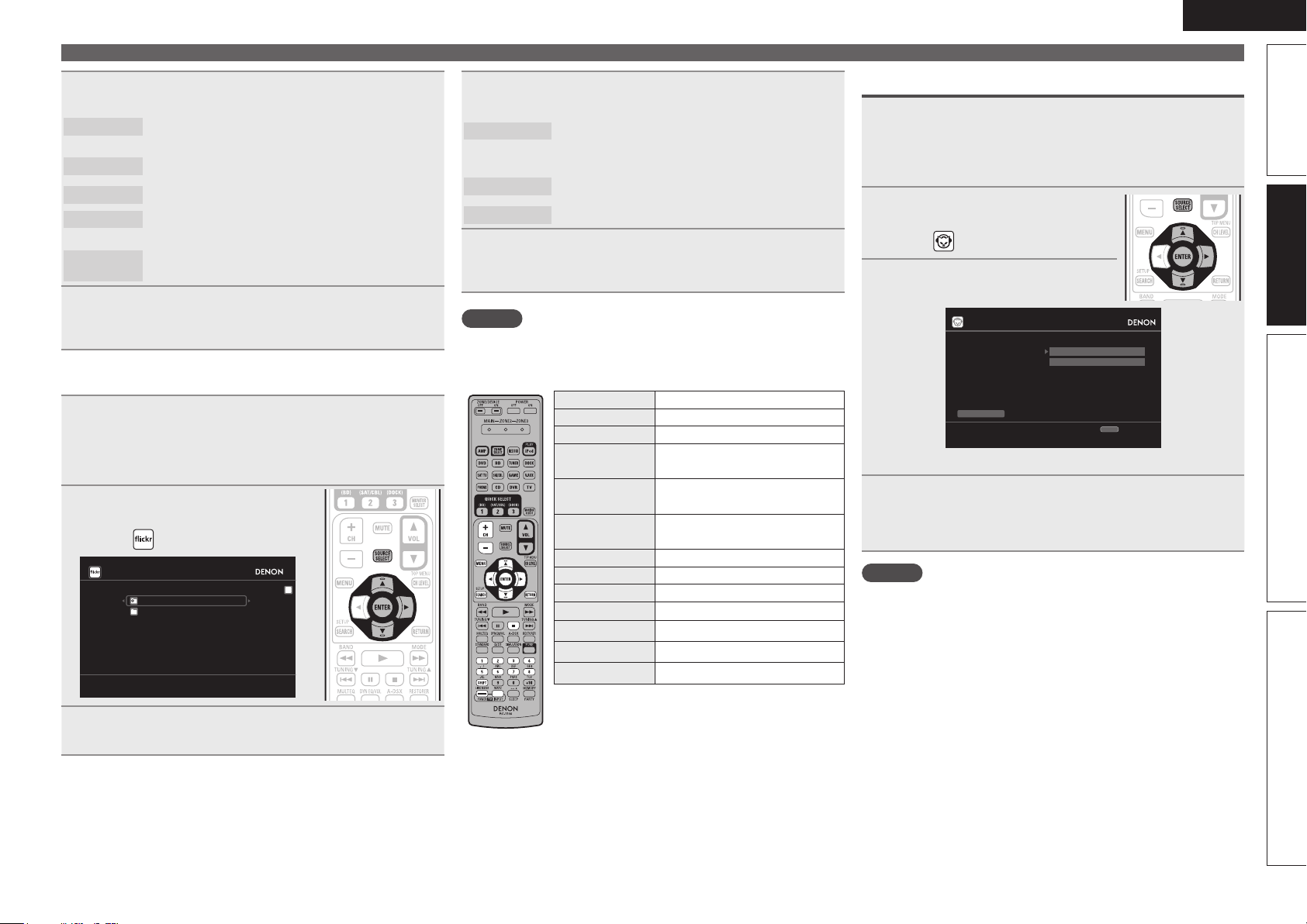
ENGLISH
Press ui to select the folder, and then press ENTER
6
or p.
Favorites
Photostream
PhotoSets
Contacts
Remove this
Contact
Displays the favorite photographs of the specified
user.
Displays a list of shared photographs.
Displays the folder (photograph album) list.
Displays a Username registered for Flickr Contact by
a particular user.
Deletes a user from Flickr Contact.
Press ui to select the le, and then press ENTER
7
or p.
The selected file is displayed.
n Viewing all photographs on Flickr
Prepare for playback.
q Check the network environment, then turn on this unit’s
1
power (vpage22 “Connecting to a home network (LAN)”).
w If settings are required, make the “Network Connecting”
(vpage79).
Press SOURCE SELECT to display
2
the Source Select menu, then
select (vpage 24).
Flickr
Add Fli ckr Contact
All Con tent
Use ui to select “All Content”, then press ENTER
3
or p.
[1/2]
Press ui to select the folder, and then press ENTER
4
or p.
Interestingness
Recent
Search by text
Displays photographs that are popular from the
number of user comments or number of times they
are added as favorites.
Displays the most recently added photographs.
Search for photographs by keyword.
Press ui to select the le, and then press ENTER
5
or p.
The selected file is displayed.
NOTE
Depending on the file format, some photographs cannot be viewed.
n Flickr operation
Operation buttons Function
CH +, – Preset channel selection
MENU Amp menu
uio p
ENTER
(Press and release)
ENTER
(Press and hold)
SEARCH Page Search
RETURN Return
2
1 – 8 Preset channel selection
SHIFT Preset channel block selection
TV POWER TV power on/standby (Default : SONY)
TV INPUT Switch TV input (Default : SONY)
z When the menu screen is displayed, press
SEARCH, then press o (previous page) or p (next
page).
To cancel, press ui or SEARCH.
Cursor operation /
Auto search (cue, ui)
Enter
Stop
z
Stop
Playing a network audio
Listening to Napster
Prepare for playback.
q Check the network environment, then turn on this unit’s
1
power (vpage22 “Connecting to a home network (LAN)”).
w If settings are required, make the “Network Connecting”
(vpage79).
Press SOURCE SELECT to display
2
the Source Select menu, then
select (vpage 24).
Use ui p to input “Username”
3
and “Password”.
Napster Account
Usernam e
Passwor d
OK
Enter U sername
• For character input, see page 61.
After inputting the “Username” and “Password”,
4
select “OK”, then press ENTER.
If the “Username” and “Password” match, the top menu for
Napster is displayed.
NOTE
• The password should be no longer than 99 characters.
• Press RETURN to cancel the input. When “Cancel input?” is
displayed, select “Yes”, then press ENTER.
RETURN
Cancel
Simple version Advanced version InformationBasic version
35
Page 40

ENGLISH
Playing a network audio
n Searching from Napster menu
Use ui to select search item or
1
folder, then press ENTER or p.
Repeat step 1 until the track is
2
displayed.
Use ui to select the track item, then press ENTER
3
or p.
n Entering a character search for the track you
want to listen to
Press SEARCH.
1
Napster
My Naps ter Library
Top 100 s
Search by Artist
New Rel eases
Search by Albums
Radio
Napster Playlists
Search by Track
E
Staff P icks
• You can search by artist name, album name or track name.
Use ui to select the search item, then press ENTER.
2
The search display appears.
Search by Artist
[1/8]
n Registering tracks in my Napster library
Press p while the track you wish
1
to register is playing.
Select “Add to my library”, then
2
press ENTER or p.
The track is entered in the Library.
Listening to tracks registered in my Napster library
Use ui to select “My Napster
1
Library”, then press ENTER or
p.
Use ui to select the information
2
or track, then press ENTER.
• To play back compressed audio with extended bass or treble
reproduction, we recommend playback in RESTORER mode
(vpage73). The default setting is “Mode3”.
• You can specify the duration of the on-screen display to be displayed
(default: 30 sec) at menu “NET/USB” (vpage83). Press uio p
to return to the original screen.
• Use
STATUS to switch between
displaying the title name, artist name or
album name.
n Napster operation
Operation buttons Function
CH +, – Preset channel selection
MENU Amp menu
uio p
ENTER
(Press and release)
ENTER
(Press and hold)
SEARCH Search menu / Page search
RETURN Return
1
8 9
2
RESTORER RESTORER
1 – 8 Preset channel selection
SHIFT Preset channel block selection
TV POWER TV power on/standby (Default : SONY)
TV INPUT Switch TV input (Default : SONY)
• Repeat playback (vpage68 “Repeat”)
• Random playback (vpage68 “Random”)
z When the menu screen is displayed, press
SEARCH twice, then press o (previous page) or
p (next page).
To cancel, press ui or SEARCH.
Cursor operation /
Auto search (cue, ui)
Enter / Pause
Stop
z
Playback / Pause
Auto search (cue)
Stop
Enter A rtist Name
0-9
SEARCH
Keyboar d
• For character input, see page 61.
SubmitInput
CH+
Insert
Input the characters, then press ENTER.
3
36
RETURN
Cancel
CH-
Delete
Page 41

ENGLISH
How to listen to Last.fm on this unit
Last.fm radio is not available in all countries. Please check www.last.
fm/hardware for more information. You’ll also need a subscription. Get
one today at www.last.fm/subscribe.
Prepare for playback.
q Make sure this unit is connected to the Internet, then turn
1
on this unit’s power (vpage22 “Connecting to a home
network (LAN)”).
w If settings are required, follow the “Network Connecting”
(vpage79).
Press SOURCE SELECT to display the Source Select
2
menu, then select (vpage 24).
Last.fm Account
I have a Last.fm acc ount
I am ne w to Last.fm
RETURN
Cancel
• If you do not have a Last.fm account, press i to select “I am new
to Last.fm”. Then press ENTER.
Create an account in accordance with the instructions on the
screen.
If you have a Last.fm account, press ui to select “I
3
have a Last.fm account”. Then press ENTER or p.
Lasst.f m Account
After inputting the username and password, select
5
“OK”, then press ENTER.
If the username and password match, the top menu for Last.
fm is displayed.
• The types of characters that can be input are as shown below.
Username:
GUpper case charactersH ABCDEFGHIJKLMNOPQRSTUVW
XYZ
GLower case charactersH abcdefghijklmnopqrstuvwxyz
GSymbolsH _ -
GNumbersH 0123456789
Password:
GUpper case charactersH ABCDEFGHIJKLMNOPQRSTUVW
XYZ
GLower case charactersH abcdefghijklmnopqrstuvwxyz
GSymbolsH ! # “ $ % & ‘ ( ) z + , - . / : ; < = > ? @ [ \ ] ^ ` { | }
˜ (Space)
GNumbersH 0123456789
Use ui to select menu and then press ENTER.
6
Popular Stations
You Recent
Stations
Your stations
Search Stations
Play popular artists and tags in your area.
Play your recent stations.
You can play tracks from the following personalised
stations (“Your Recommeded Radio”, “Your
Library”, “Your Neighborhood”, “Your Freiends’
Radio”, “Your Top Tags”,“Your Top Artists”.
You can search station by Artist or Tag.
Playing a network audio
Menu items on playback screen.
8
Love this track
Ban this track
Scrobbling
NOTE
• The password should be no longer than 99 characters.
• Press RETURN to cancel the input. When “Cancel input?” is
displayed, select “Yes”, then press ENTER.
Loving tracks improves your Last.fm
recommendations, and you can optionally share
them on popular social networks.
If you ban a track, we won’t play it again. You can
undo this on the Last.fm website.
Scrobbling sends the tracks you played to your
Last.fm account. You can see charts of the music
you’ve been listening to, get recommendations for
new music and events in your area and share your
listening tastes with your friends. You can turn this
service on or off using this option. The more you
scrobble, the better your recommendations will
become.
Menu [1/3]
Love th is track
Ban thi s track
Scrobbl ing(On)
Simple version Advanced version InformationBasic version
Usernam e
Passwor d
OK
Enter U sername
This se rvice is curr ently
availab le in limited countries.
RETURN
Cancel
Use ui p to enter your username and password.
4
• For character input, see page 61.
Use ui to select a station, and press ENTER or
7
PLAY to start playback.
Playback starts and the following screen appears.
rock Ra dio
Now Pla ying
00:03
100%
Song
Artist
Album
Skip Select
MP3 128 kbps
Menu
• To play back compressed audio with extended bass or treble
reproduction, we recommend playback in RESTORER mode
(vpage73). The default setting is “Mode3”.
• You can specify the duration of the on-screen display to be displayed
(default: 30 sec) at menu “NET/USB” (vpage83). Press uio p
to return to the original screen.
• Use
STATUS to switch between
displaying the title name, artist name or
album name.
37
Page 42

ENGLISH
Playing a network audio
n Last.fm operation
Operation buttons Function
MENU Amp menu
uio p
ENTER
(Press and release)
ENTER
(Press and hold)
SEARCH Page search
RETURN Return
9
RESTORER RESTORER
TV POWER TV power on/standby (Default : SONY)
TV INPUT Switch TV input (Default : SONY)
z When the menu screen is displayed, press
SEARCH, then press o (previous page) or p (next
page).
To cancel, press ui or SEARCH.
Playing a USB memory device
Playing back music or still picture (JPEG) files recorded on a USB
memory device.
Cursor operation /
Auto search (cue, i)
Important information
n USB memory devices
Enter
Stop
z
1
2
Playback
Auto search (cue)
Stop
A USB memory device can be connected to the USB port of this
unit to play music and still picture (JPEG) files stored on the USB
memory device.
Also, files stored on an iPod can be played when the iPod is
connected directly to the USB port of this unit. See “Connect an
iPod directly to the USB port to play back” (vpage27).
• Only USB memory devices conforming to mass storage class and
MTP (Media Transfer Protocol) standards can be played on this
unit.
• This unit is compatible with USB memory devices in “FAT16” or
“FAT32” format.
Album art function
When an MP3 music file includes album art data, the album art can be
displayed while playing the file.
Slide show function
Still picture (JPEG) files stored on USB memory devices can be played
as slide shows.
The duration each picture is displayed can be set.
This unit plays back image (JPEG) files in the orientation in which they
are stored in the folder.
WMA (Windows Media Audio)
MP3 (MPEG-1 Audio Layer-3)
WAV
MPEG-4 AAC
FLAC (Free Lossless Audio Codec)
JPEG
z1 USB
• This unit is compatible with MP3 ID3-Tag (Ver. 2) standard.
• This unit can show the artwork that was embedded by using
MP3 ID3-Tag Ver. 2.3 or 2.4.
• This unit is compatible with WMA META tags.
• WAV format Quantization bit rate: 16 bits.
• FLAC format Quantization bit rate: 16/24 bits.
z2 Copyright-protected files can be played on certain portable
players compatible with MTP.
z3 Only files that are not protected by copyright can be played on
this unit.
Content downloaded from pay sites on the Internet are copyright
protected. Also, files encoded in WMA format when ripped from
a CD, etc. on a computer may be copyright protected, depending
on the computer’s settings.
WMA (Windows
Media Audio)
MP3 (MPEG-1
Audio Layer-3)
WAV 32/44.1/48 kHz – .wav
MPEG-4 AAC 32/44.1/48 kHz 16 – 320 kbps
FLAC (Free
Lossless Audio
Codec)
GCompatible formatsH
USB memory devices
z2
P
P
P
z3
P
P
P
GCompatible formatsH
Sampling
frequency
32/44.1/48 kHz 48 – 192 kbps .wma
32/44.1/48 kHz 32 – 320 kbps .mp3
32/44.1/48/
88.2/96 kHz
Bit rate Extension
.aac/
.m4a/
.mp4
– .flac
z1
38
Page 43

ENGLISH
Playing files stored on USB memory
devices
Connect the USB memory device to the USB port
1
(vpage 19 “Connecting an iPod or USB memory
device to the USB port”).
Press NET/USB to switch the
2
input source to “NET/USB”.
DENON:[ AVR-3311]
favorit e
Interne t Radio
Media S erver
USB
Flickr
Last.fm
Napster
Use ui to select “USB”, then
3
press ENTER or p.
USB
D&M1
D&M2
D&M3
Music1. mp4
Music2. mp3
Music3. m4a
Music4. m4a
• Selecting in the “Source Select” menu, lets you directly select
“USB”.
Press ui to select the search item or folder, then
4
press ENTER or p.
Press ui to select the le, then press ENTER, p or
5
1.
Playback starts.
[1/8]
[1/7]
• You can specify the duration of the on-screen display to be displayed
(default: 30 sec) at menu “NET/USB” (vpage83). Press uio p
to return to the original screen.
• To play back compressed audio with extended bass or treble
reproduction, we recommend playback in RESTORER mode
(vpage73). The default setting is “Mode3”.
• If the USB memory device is divided into multiple partitions, only the
top partition can be selected.
• This unit is compatible with MP3 files conforming to “MPEG-1 Audio
Layer-3” standards.
• When USB on the sub remote control unit is pressed, playback starts
from the first file stored on the USB memory device.
NOTE
• Note that DENON will accept no responsibility whatsoever for any
problems arising with the data on a USB memory device when using
this unit in conjunction with the USB memory device.
• USB memory devices will not work via a USB hub.
• DENON does not guarantee that all USB memory devices will
operate or be supplied power. When using a USB portable hard disk
that can draw power from an AC adapter, we recommend using the
AC adapter.
• It is not possible to connect and use a computer via the USB port of
this unit using a USB cable.
n USB operation
Operation buttons Function
(Press and release)
(Press and hold)
• Repeat playback (vpage68 “Repeat”)
• Random playback (vpage68 “Random”)
z1 When the menu screen is displayed, press
z2 When the menu screen is displayed, press
Playing a USB memory device
CH +, – Preset channel selection
MENU Amp menu
uio p
ENTER
ENTER
SEARCH Page search
RETURN Return
1
8 9
3
2
RESTORER RESTORER
1 – 8 Preset channel selection
SHIFT Preset channel block selection
TV POWER TV power on/standby (Default : SONY)
TV INPUT Switch TV input (Default : SONY)
Cursor operation /
Auto search (cue, ui)
Enter / Pause
Stop
z1
/ Character search
Playback / Pause
Auto search (cue)
Pause
Stop
z2
SEARCH, then press o (previous page) or p
(next page).
To cancel, press ui or SEARCH twice.
SEARCH twice, then press o p to select the
first letter you want to search mode.
• If it is not possible to search the list, “unsorted
list.” is displayed.
To cancel, press ui or SEARCH.
If the list is not in alphabetical order, you may
not be able to perform a character search.
Simple version Advanced version InformationBasic version
39
Page 44

ENGLISH
Selecting a listening mode (Surround mode)
This unit can play input audio signals in multi-channel surround mode or in stereo mode.
Select a listening mode suitable for the playback contents (cinema, music, etc.) or according to your liking.
Standard playback
Listening mode
Input audio
signal
2-channel
Multi channel
2-channel
Multi channel
2-channel
Multi channel
2-channel
Multi channel
2-channel
Multi channel
• Some listening modes cannot be selected, depending on the audio format or number of channels of the input signal. For details, see “Types
of input signals, and corresponding surround modes” (vpage103).
• Adjust the sound field effect with the menu “Surround Parameter” (vpage69) to enjoy your favorite sound mode.
Playback Listening mode
Surround
Surround
Stereo
Stereo
Surround
Stereo
Surround
Standard playback
(vpage40)
DENON original
surround playback
(vpage42)
Stereo playback
(vpage42)
Direct playback
(vpage42)
Pure direct playback
(vpage42)
For 2-channel signal input:
• Surround-channel signals are created and played with surround playback.
For multichannel signal input:
• The surround signal recorded in source is played as surround playback.
(The sound is played according to the settings of the speaker size in
“Speaker Config.” (vpage75).)
• Surround-back-channel or front-height-channel signals that are not
recorded in source can be created.
The surround effects suitable for the source type or according to your
liking can be selected from the DENON original sound mode and is used
for playback.
• If multichannel signals are input, they are mixed down to 2-channel audio
and are played.
• Subwoofer signals are also output.
Sound recorded in source is played as is.
• Surround back signals or front height signals are not created.
• In this mode, the following items cannot be adjusted.
• Tone (vpage70) • MultEQ® XT (vpage71)
• Dynamic EQ® (vpage71) • Dynamic Volume® (vpage72)
• RESTORER (vpage73)
This mode is for playback in higher sound quality than in ”Direct playback”
mode. The following circuits that affect sound quality are set to off.
• Main unit’s display circuit (The display is turned off.)
• Analog video input/output circuit
n Surround playback of 2-channel sources
Playing the source (vpage 25 –
1
39).
Press STANDARD to select the
2
surround decoder to play back
multichannel sound.
• If STANDARD on the main unit is pressed,
the same function as with the remote
control unit can be obtained.
• Each time STANDARD is pressed, the
surround mode is switched.
Which decoder can be selected depends on
the settings of “Amp Assign” (vpage75)
or “Speaker Config.” (vpage75).
z1
DOLBY PLgz
DOLBY PLgx
DOLBY PLg
DTS NEO:6
z1 This can be selected when “Amp Assign” is set to “Normal” or
“Speaker Config.” – “F.Height” is not set to “None”.
z2 This can be selected when “Amp Assign” is set to “Normal” or
“Speaker Config.” – “S.Back” is not set to “None”.
This mode is for 7.1-channel surround playback
using the front height speakers.
• “PLgz Height” is displayed.
z2
This mode is for 7.1-channel or 6.1-channel
surround playback using the surround back
speakers.
• “PLgx Cinema”, “PLgx Music”or “PLgx Game”
is displayed.
This mode is for 5.1-channel surround playback.
Select this mode if no front height speaker nor
surround back speaker is to be used.
• “PLg Cinema”, “PLg Music”, “PLg Game” or
“Pro Logic” is displayed.
This mode is for 7.1-channel, 6.1-channel or
5.1-channel surround playback using the surround
back speakers.
• “DTS NEO:6 cinema” or “DTS NEO:6 music” is
displayed.
40
Page 45

ENGLISH
Select the mode corresponding to the playback
3
contents with the menu “Surround Parameter” –
“Mode” (vpage 69) to enjoy your favorite sound
mode.
Cinema
Music
Game
Pro Logic
Height
• If the menu “Surround Parameter” – “F.Height” (vpage69) is set
to “ON”, the mode is switched to “Height” mode.
GViews on the displayH
This mode is suited for movie sources.
This mode is suited for music sources. More sound
is sent to the front speakers than in “Cinema”
mode.
This mode is suited for games.
This mode is suitable for playback of 2-channel
sources recorded with Dolby Pro Logic.
z
This mode is for the surround decoder “Dolby
PLgz”. If the surround decoder is “Dolby PLgz”,
another mode cannot be selected.
q Shows a decoder to be
used.
q w
w Shows a Audyssey
DSX™ processing.
n Surround playback of multi-channel sources
(Dolby Digital, DTS etc.)
Playing the source (vpage 25 –
1
39).
Press STANDARD to select the
2
surround decoder to play back
multichannel sound.
• If STANDARD on the main unit is
pressed, the same function as with the
remote control unit can be obtained.
• Select the surround mode while
viewing the display on the screen
(v“Displaying the currently playing
surround mode” at right).
• Which decoder can be selected depends on the input signal,
the settings of “Amp Assign” (vpage75) or “Speaker Config.”
(vpage75).
Displaying the currently playing surround mode
Input signal Surround mode Display
DOLBY DIGITAL
(other than 2ch) /
DOLBY DIGITAL EX
DOLBY DIGITAL Plus
DOLBY TrueHD
DTS (5.1ch) /
DTS-ES Discrete 6.1 /
DTS-ES Matrix 6.1 /
DTS 96/24
DTS-HD
PCM (multi ch)
All signals indicated
above
DOLBY DIGITAL
DOLBY DIGITAL EX
DOLBY DIGITAL + PLgx
CINEMA
DOLBY DIGITAL + PLgx MUSIC
DOLBY DIGITAL + PLgz HEIGHT
DOLBY DIGITAL Plus
DOLBY DIGITAL Plus + EX
DOLBY DIGITAL Plus + PLgx
CINEMA
DOLBY DIGITAL Plus + PLgx
MUSIC
DOLBY DIGITAL Plus + PLgz
HEIGHT
DOLBY TrueHD
DOLBY TrueHD + EX
DOLBY TrueHD + PLgx CINEMA
DOLBY TrueHD + PLgx MUSIC
DOLBY TrueHD + PLgz HEIGHT
DTS SURROUND
DTS + PLgx CINEMA
DTS + PLgx MUSIC
DTS + PLgz HEIGHT
DTS + NEO:6
DTS ES MTRX6.1
DTS ES DSCRT6.1
DTS 96/24
DTS-HD HI RES
DTS-HD MSTR
DTS-HD + NEO:6
DTS-HD + PLgx CINEMA
DTS-HD + PLgx MUSIC
DTS-HD + PLgz HEIGHT
DTS Express
MULTI CH IN
MULTI IN + Dolby EX
MULTI IN + PLgx CINEMA
MULTI IN + PLgx MUSIC
MULTI IN + PLgz HEIGHT
MULTI CH IN 7.1
Audyssey DSX
z1
z2
z3
z4
DOLBY DIGITAL
DOLBY DIGITAL EX
DOLBY D PL x C
DOLBY D PL x M
DOLBY D PL z
DOLBY DIGITAL +
DOLBY D + EX
DOLBY D + PL x C
DOLBY D + PL x M
DOLBY D + PL z
DOLBY TrueHD
DOLBY HD EX
DOLBY HD PL x C
DOLBY HD PL x M
DOLBY HD PL z
DTS SURROUND
DTS PL x C
DTS PL x M
DTS PL z
DTS NEO:6
DTS ES MTRX6.1
DTS ES DSCRT6.1
DTS 96/24
DTS-HD HI RES
DTS-HD MSTR
DTS-HD NEO:6
DTS-HD PL x C
DTS-HD PL x M
DTS-HD PL z
DTS Express
MULTI CH IN
MULTI Dolby EX
MULTI IN PL x C
MULTI IN PL x M
MULTI IN PL z
MULTI CH IN 7.1
Audyssey DSX
Standard playback
z1 This is displayed when the input signal
is “DTS-ES Matrix 6.1” and this unit’s
“AFDM” (vpage70) setting is “ON”.
z2 This is displayed when the input signal is
“DTS-ES Discrete 6.1”.
z3 This is displayed when the input signal is
“DTS 96/24”.
z4 This surround mode is displayed when
“Audyssey DSX” (vpage 72) is set to
“ON–Height–” or “ON-–Wide–”.
GViews on the displayH
q w
q Shows a decoder to be used.
• A DOLBY DIGITAL Plus decoder is displayed
as “DOLBY D +”.
w Shows a decoder that creates sound output
from the surround back speakers.
• “+ PLgz” indicates the front height sound
from front height speakers.
For an input signal that can be reproduced in
each surround mode, see “Surround modes and
parameters” (vpage101).
Simple version Advanced version InformationBasic version
41
Page 46

ENGLISH
DENON original surround playback
Playing the source (vpage 25 –
1
39).
Press SIMULATION to select the
2
surround mode.
• If DSP SIMULATION on the main unit is
pressed, the same function as with the
remote control unit can be obtained.
• Each time SIMULATION is pressed, the
surround mode is switched.
MULTI CH
STEREO
ROCK ARENA
JAZZ CLUB
MONO MOVIE
VIDEO GAME
MATRIX
VIRTUAL
z When playing sources recorded in monaural in the “MONO
MOVIE” mode, the sound will be off balance with a single
channel (left or right), so input to both channels.
Depending on the program source being played, it may not be possible
to achieve a satisfactory surround effect. In this case, try other modes
to achieve a sound field suited to your tastes.
NOTE
When the input signal is Dolby TrueHD, Dolby Digital Plus, DTS-HD
or DTS Express, you cannot select DENON original surround mode.
This mode is for enjoying stereo sound from all
speakers.
This mode is for enjoying the atmosphere of a live
concert in an arena.
This mode is for enjoying the atmosphere of a live
concert in a jazz club.
z
This mode is for playing monaural movie sources
with surround sound.
This mode is suited for achieving surround sound
with video games.
This mode lets you add a spacious feel to stereo
music sources.
This mode is for enjoying surround effects using
only the front speakers or headphones.
Stereo playback
This is the mode for playing in stereo. The tone can be adjusted.
• Sound is output from the front left and right speakers and subwoofer.
• If multichannel signals are input, they are mixed down to 2-channel
audio and are played.
Playing the source (vpage 25 –
1
39).
Press D/ST to select “STEREO”.
2
Stereo playback begins.
• If
DIRECT/STEREO on the main unit is
pressed, the same function as with the
remote control unit can be obtained.
Direct playback
Sound recorded in source is played as is.
• Surround back signals or front height signals are not created.
• In this mode, the following items cannot be adjusted.
• Tone (vpage70) • MultEQ® XT (vpage71)
• Dynamic EQ® (vpage71) • Dynamic Volume® (vpage72)
• RESTORER (vpage73)
Playing the source (vpage 25 –
1
39).
Press D/ST to select “DIRECT”.
2
Direct playback begins.
• If
DIRECT/STEREO on the main unit is
pressed, the same function as with the
remote control unit can be obtained.
Pure direct playback
This mode is for playback in higher sound quality than in “Direct
playback” mode.
• The following circuits that affect sound quality are set to off.
• Main unit’s display circuit (The display is turned off.)
• Analog video input/output circuit
• Surround back signals or front height signals are not created.
• In this mode, the following items cannot be adjusted.
• Tone (vpage70) • MultEQ® XT (vpage71)
• Dynamic EQ® (vpage71) • Dynamic Volume® (vpage72)
• RESTORER (vpage73)
Playing the source (vpage 25 –
1
39).
Press PURE.
2
The display goes dark, and pure direct
playback begins.
• If
PURE DIRECT on the main unit is
pressed, the same function as with the
remote control unit can be obtained.
• To cancel, press PURE again.
• Video signals are only output when HDMI signals are played in the
PURE DIRECT mode.
NOTE
When in the PURE DIRECT mode, the menu screen is not displayed.
42
Page 47

Advanced
version
Advanced version
Here, we explain functions and operations that let you make better use of this unit.
F Speaker installation/connection (Advanced connection) vpage44
F Playback (Advanced operation) vpage50
F Playback in ZONE2/ZONE3 (Separate room) vpage57
F How to make detailed settings vpage59
F Operating the connected devices by remote control unit vpage87
ENGLISH
Basic versionSimple version InformationAdvanced version
43
Page 48

ENGLISH
z
Speaker installation/connection (Advanced connection)
This section provides the installation, connection,
and setup methods of speaker systems other
than the 7.1-channel system (with surround back
speakers).
For the speaker installation, connection, and setup
methods of the 7.1-channel system with surround
back speakers, see “Simple version (Simple setup
guide)” (vpage3).
Use the Audyssey® Auto Setup function of this unit
to automatically detect the number of connected
speakers and perform optimal settings for the
speakers to be used.
Procedure for speaker settings
Install
Connect (vpage45)
Set up speakers (vpage48)
Install
This unit is compatible with Audyssey DSX™ (vpage106) and
Dolby Pro Logic gz (vpage107), which offers an even wider and
deeper surround sensation.
When using Audyssey DSX, install front wide speakers or front
height speakers.
When using Dolby Pro Logic gz, install front height speakers.
Install the surround back speakers in a position 60 to 90 cm higher
than ear level.
z2
45˚
Surround
speaker
60 – 90 cm
Surround back
speaker
• Point slightly
downwards
Front height
speaker
• Point slightly
downwards
At least 1 m
Front
speaker
z1 Recommended for Dolby Pro Logic gz
z2 Recommended for Audussey DSX
Front wide
1
speaker
GViewed from the sideH
When 7.1ch (Surround back / Front height / Front
wide speaker) installed
FHRFHL
FL
SW
FWL
SL
z1 22˚ – 30˚ z2 22˚ – 45˚ z3 55˚ – 60˚
z4 90˚ – 110˚ z5 135˚ – 150˚
z3
z2
z1
Listening
position
SBL SBR
FR
C
z5
z4
FWR
SR
When 6.1ch (Surround back speaker) installed
NOTE
Sound is not output simultaneously from the surround back speakers,
front height speakers, and front wide speakers. You can switch
between speakers by changing the settings in surround mode or
Audyssey DSX.
SL
FL FR
SW
C
z1
z2
Listening position
SB
z1 22˚ – 30˚ z2 90˚ – 110˚
SR
44
Page 49

ENGLISH
When 5.1ch installed
FL FR
SW
C
z1
z2
SL
Listening
position
z1 22˚ – 30˚ z2 120˚
When Front A/B speakers installed
FL(B) FL(A)
SW
FR(A) FR(B)
SR
Install
Connect
• For the method of connecting the 7.1-channel system with surround back speakers, see page 4.
• For the method of connecting the TV, see page 5.
7.1-channel (Surround back / Front height / Front wide speaker) connection
For 7.1-channel (Surround back / Front height / Front wide speaker) playback, set “Set up “Amp Assign”” (vpage49) to “Normal”.
Basic versionSimple version InformationAdvanced version
Listening position
FL Front speaker (L) SBL Surround back speaker (L)
FR Front speaker (R) SBR Surround back speaker (R)
C Center speaker FHL Front height speaker (L)
SW Subwoofer FHR Front height speaker (R)
SL Surround speaker (L) FWL Front wide speaker (L)
SR Surround speaker (R) FWR Front wide speaker (R)
SB Surround back speaker
For speaker impedance and speaker cable connections, see page 4.
SL
FL FR
SW
C
SBL SBR
FHRFHL
FWRFWL
SR
45
Page 50

ENGLISH
Connect
6.1-channel (Surround back speaker) connection
If using only one surround back speaker (with a 6.1-channel connection), connect to the “L” side of the
SURR. BACK/AMP ASSIGN terminal.
For speaker settings in this case, see “When 6.1ch (Surround back speaker) installed” (vpage44).
For 6.1-channel (Surround back speaker) playback, set “Set up “Amp Assign”” (vpage49) to “Normal”.
FL FR
SW
C
5.1-channel connection
For 5.1-channel playback, set “Set up “Amp Assign”” (vpage49) to “Normal”.
FL FR
SW
C
46
SL
SB
SL
SR
For speaker impedance and speaker cable connections, see page 4.
SR
Page 51

Front A/B connection
The second set of front speakers can be connected to the SURR.
BACK/AMP ASSIGN terminals.
In this case, set “Set up “Amp Assign”” (vpage49) to “Front B”.
SW
2.1-channel connection
FL FR
SW
ENGLISH
Connect
Bi-Amp connection
A bi-amp connection is to connect separate amplifiers to the tweeter
terminals and woofer terminals of speakers compatible with the
bi-amp function. This prevents the back electromotive force (returned
force without output) of the woofer sent to the tweeter, which affects
the sound quality of the tweeter, and you can enjoy playback with
higher-quality sound.
In this case, set “Set up “Amp Assign”” (vpage49) to “Bi-Amp”.
Basic versionSimple version InformationAdvanced version
wq wq
FL FR
(R) (L)
FL(A)FL(B) FR(B)FR(A)
For surround playback of a multichannel source, if you connect the
center speaker, surround speakers and subwoofers, 5.1-channel
playback is available.
Front speakers can be used separately, depending on the speaker’s
specifications or playback source such as front speakers (A) for
multichannel playback and front speakers (B) for 2-channel playback
(vpage77 “Front Speaker Setup”).
For speaker impedance and speaker cable connections, see page 4.
n For connecting two subwoofers
Two subwoofers can be connected to this unit.
The same signal is output from each subwoofer terminal.
When making a bi-amp connection, the same signal is output from the
front speaker terminal and the SURR.BACK/AMP ASSIGN terminal.
For surround playback of a multichannel source, if you connect the
center speaker, surround speakers and subwoofers, 5.1-channel
playback is available.
NOTE
• Use speakers compatible with bi-amp connections.
• When making bi-amp connections, be sure to remove the shortcircuiting plate or wire between the speaker’s woofer and tweeter
terminals.
47
Page 52

ENGLISH
Connect
5.1-channel + 2.1-channel connection
If front speakers for 2-channel playback are connected to the SURR. BACK/AMP ASSIGN terminals, both
speakers for multichannel playback and for 2-channel playback can be used, by switching.
In this case, set “Set up “Amp Assign”” (vpage49) to “2CH”.
Multi channel playback
(Surround mode)
Switching
Set up speakers
This section provides the setup methods of speaker systems other than the 7.1-channel system
(with surround back speakers).
For the setup methods of the 7.1-channel system with surround back speakers, see “Simple
version”, “Set up speakers (Audyssey® Auto Setup)” (vpage6) of “Simple version”.
First install and connect the speakers to this unit.
Before Auto Setup measurement, the settings shown below can be made.
• Changing the amplifier assignment (Amp Assign)
The signal output from the SURR.BACK/AMP ASSIGN speaker terminal of this unit can be switched to
match your speaker environment (vpage49 “Set up “Amp Assign””).
• Setting the channels to be used (Channel Select)
If channels that are not to be used are set in advance, measurement for the set channels is skipped, and
measuring time can be reduced (vpage49 “Set up “Channel Select””).
1
Set up the
2
around items indicate the settings.
Connect the setup microphone.
remote control unit
n Set up the zone mode
Press ZONE SELECT to switch the
zone mode to “MAIN”.
The “MAIN” indicator lights.
When the setup microphone is
connected, the following screen is
displayed.
FLFL FR FR
SW
C
2-channel playback
SL
• For switching multichannel playback and 2-channel playback, see “Selecting a listening mode (Surround
mode)” (vpage40).
• If “2ch Direct/Stereo” – “Setting” (vpage78) is set to “Custom”, settings for 2-channel playback
speakers can be made.
48
SR
(Direct/Stereo mode)
For speaker impedance and speaker cable connections, see page 4.
Press ZONE SELECT
n Set up the operation mode
Press AMP to set the remote control
unit to amplier operation mode.
Press AMP
AUTO SE TUP
AUDYSSE Y AUTO SETUP
STE P1 Pre parati on
Con nect t he spe akers
and place them accord ing to th e reco mmenda tio ns in the ma nual.
Set the f ollowi ng
ite ms if necess ary.
Amp Assig n
Cha nnel S elect
Aut o Setu p Star t
Sta rt Aut o Setu p
ENT ER Enter RET URN Ca ncel
Mul tEQ XT
[1/ 6]
Page 53

ENGLISH
Set up speakers
3
Set up “Amp Assign”
Use ui to select “Amp Assign”,
and then press ENTER.
AUTO SE TUP
AUDYSSE Y AUTO SETUP
STE P1 Pre parati on
Con nect t he spe akers
and place them accord ing to th e reco mmenda tio ns in the ma nual.
Set the f ollowi ng
ite ms if necess ary.
Amp Assig n
Cha nnel S elect
Aut o Setu p Star t
Set use o f surr ound b ack ch . for your s ystem
ENT ER Enter RET URN Ca ncel
Mul tEQ XT
Use o p to select the conguration
4
of the connected speakers, and then
press RETURN.
Normal
ZONE2
ZONE3
ZONE2/3-
MONO
Bi-Amp
2CH
Set when using surround
back, front height or front wide
speakers. In this case, go to step
6.
Set for connecting the speakers
for ZONE2 to the SURR. BACK/
AMP ASSIGN terminals.
Set for connecting the speakers
for ZONE3 to the SURR. BACK/
AMP ASSIGN terminals.
Set to output the ZONE2 and
ZONE3 sound in monaural, and
to output the L side of the SURR.
BACK/AMP ASSIGN terminal
from ZONE2, and the R side from
ZONE3.
Set for connecting a tweeter
of a front speaker to the SURR.
BACK/AMP ASSIGN terminals
and a woofer of the front speaker
to the FRONT terminals.
Set for 2-channel direct/stereo
playback. When “2CH” is set,
connect the second set of front
speakers to the SURR.BACK/
AMP ASSIGN terminals.
[1/ 6]
Front B
5
Set for connecting the second set
of front speakers to the SURR.
BACK/AMP ASSIGN terminals.
Set up “Channel Select”
Use ui to select “Channel Select”,
and then press ENTER.
AUTO SE TUP
AUDYSSE Y AUTO SETUP
STE P1 Pre parati on
Con nect t he spe akers
and place them accord ing to th e reco mmenda tio ns in the ma nual.
Set the f ollowi ng
ite ms if necess ary.
Amp Assig n
Cha nnel S elect
Aut o Setu p Star t
Ski p unus ed ch’ s meas uremen t for timesa ving
ENT ER Enter RET URN Ca ncel
Mul tEQ XT
Use ui to select a channel.
6
Front
Subwoofer
Surround
Back
Front
Height
Front Wide
Select for setting the front speakers
to be used. In this case, go to step
7.
• “Front” can be set when “Amp
Assign” is set to “Front B”.
Select for no subwoofers to be
used. In this case, go to step 8.
Select for no surround back
speakers to be used. In this case,
go to step 9.
• “Surround Back” can be set when
“Amp Assign” is set to “Normal”.
Select for no front height speakers
to be used. In this case, go to step
10.
• “Front Height” can be set when
“Amp Assign” is set to “Normal”.
Select for no front wide speakers to
be used. In this case, go to step 10.
• “Front Wide” can be set when
“Amp Assign” is set to “Normal”.
[1/ 6]
GWhen “Front” is selected in step 6H
7
Press o p to select a front speaker.
A
Select this to use front speaker A.
B
Select this to use front speaker B.
A+B
Select this to use front speakers A and B
simultaneously.
GWhen “Subwoofer” is selected in
8
step 6H
Use o p to select the item.
Measure
9
Set for measuring a subwoofer.
Skip
Set for no measuring of a subwoofer.
GWhen “Surround Back” is selected
in step 6H
Use o p to select the item.
Measure
(2spkrs)
Measure
(1spkr)
10
Set for measuring two surround back
speakers.
Set for measuring a surround back
speaker.
Set for no measuring of a surround
Skip
back speaker.
GWhen “F.Height” or “F.Wide” is
selected in step 6H
Use o p to select the item.
Measure
Set to measure the front height
speakers or front wide speakers.
Skip
Set when you do not want to measure
the front height speakers or front wide
speakers.
Press RETURN.
11
Proceed to page 8
step 6.
STEP1 Preparation
NOTE
After performing Audyssey® Auto Setup, do not
change the speaker connections or subwoofer
volume. In event of a change, perform Audyssey
Auto Setup again.
Basic versionSimple version InformationAdvanced version
Remote control operation
buttons
Move the cursor
(Up/Down/Left/Right)
Confirm the setting Return to previous menu
49
Page 54

ENGLISH
Playback (Advanced operation)
Playback (Basic operation) (vpage24)
Selecting a listening mode (Surround mode)
(vpage40)
n HDMI control function (vpage50)
n Sleep timer function (vpage51)
n Adjusting the volume of the speakers (vpage51)
n Quick select function (vpage52)
n REC OUT mode (vpage52)
n Party mode function (vpage53)
n Operating a wireless LAN-compatible mobile
terminal to play music and still pictures (vpage54)
n Web control function (vpage55)
n Various memory functions (vpage56)
Convenient functions
HDMI control function
When you make an HDMI connection with a TV or player compatible
with this unit and HDMI control functions, you can perform the
following operations by setting the HDMI control function of each
device.
n This unit power off can be linked to the TV power off
step.
n You can switch audio output devices with a TV
operation.
When you set “Output audio from amp” in the TV audio output
setup operation, you can switch the amp power on.
n You can adjust this unit volume in the TV volume
adjustment operation.
n You can switch this unit input sources through
linkage to TV input switching.
n When playing the player, this unit input source
switches to the source for that player.
NOTE
• The HDMI control function only supports the HDMI MONITOR
OUT 1 connector. To use the HDMI control function, connect the
television to the HDMI MONITOR OUT 1 connector.
• When “HDMI Control” is set to “ON”, it consumes more
standby power.
• The HDMI control function controls operations of a TV that is
compatible with the HDMI control function. Make sure that the TV
and HDMI are connected when you perform HDMI control.
• Some functions may not operate depending on the connected TV
or player. Check the owner’s manual of each device for details
beforehand.
• When “Power Off Control” on the menu is set to “OFF” (vpage78),
this unit is not set to standby even if the connected device is in the
standby mode.
• When connection changes are implemented, such as adding
connections to HDMI devices, linked operations may be initialized.
In this case, you will need to reconfigure the settings.
• When “HDMI Control” is set to “ON”, it is not possible to assign an
HDMI connector to “TV” at “Input Assign” (vpage65).
Set the HDMI output connector corresponding with
1
the HDMI control function.
Set “HDMI Control” (vpage78) to “ON“.
Turn the power on for all the equipment connected
2
by HDMI cable.
Set the HDMI control function for all equipment
3
connected by HDMI cable.
• Please consult the operating instructions for the connected
equipment to check the settings.
• Carry out steps 2 and 3 should any of the equipment be unplugged.
Switch the television input to the HDMI input
4
connected to this unit.
Switch this unit input to the HDMI input source and
5
check if the picture from the player is ok.
When you turn the TV’s power to standby, check
6
that the power of this unit also goes to standby.
If the HDMI control function does not operate properly, check the
following points.
• Is the TV or player compatible with the HDMI control function?
• Is “HDMI Control” (vpage78) set to “ON”?
• Is “Power Off Control” (vpage78) set to “All” or “Video”?
• Are the HDMI control function settings of all equipment correct?
• Is the television connected to the HDMI MONITOR OUT 1 connector?
NOTE
Should any of the operations below be performed, the interlocking
function may be reset, in which case, repeat steps 2 and 3.
• “Input Assign” – “HDMI” (vpage65) setting has changed.
• “Monitor Out” (vpage77) setting is changed.
• There is a change to the connection between the equipment and the
HDMI, or an increase in equipment.
50
Page 55
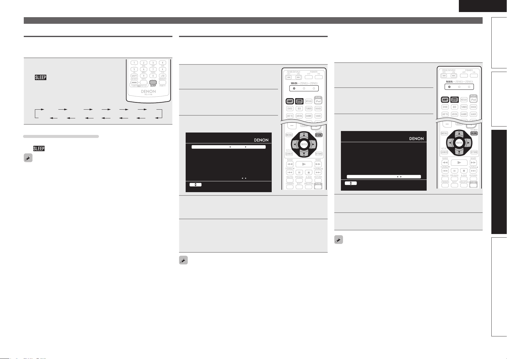
Sleep timer function
OFF 10 min 20 30 40 50
The power automatically goes into standby once the set time has
elapsed.
This is convenient for playing sources while going to sleep.
Press SLEEP and display the time you
want to set.
The indicator on the display lights.
• The time switches as shown below each
time SLEEP is pressed.
120
110
To cancel the sleep timer
Press SLEEP to set “OFF”.
The indicator on the display turns off.
• The sleep timer setting is canceled if this unit’s power is set to
standby or turned off.
• When power to the main zone is turned off with the sleep timer,
power in ZONE2 and ZONE3 are also turned off.
6080 7090100
Adjusting the volume of the speakers
You can adjust the channel level either according to the playback
sources or to suit your taste, as described below.
n Adjusting the volume of the different speakers
Press ZONE SELECT to switch the
1
zone mode to “MAIN”.
The “MAIN” indicator lights.
Press AMP to set the remote
2
control unit to amplier operation
mode.
Press CH LEVEL.
3
CHANNEL LEVEL
Fro nt L
Fro nt R
Cen ter
Sub woofer
Sur round L
Sur round R
S.B ack L
S.B ack R
Fad er
Sel ect
0.0 dB
0.0 dB
0.0 dB
0.0 dB
0.0 dB
0.0 dB
0.0 dB
0.0 dB
Fro nt Rear
Convenient functions
n Adjusting the volume of groups of speakers
(Fader function)
This function lets you adjust (fade) the sound all at once from the
front (front speaker / front height speaker / front wide speaker /
center speaker) or rear (surround speaker / surround back speaker).
Press ZONE SELECT to switch the
1
zone mode to “MAIN”.
The “MAIN” indicator lights.
Press AMP to set the remote
2
control unit to amplier operation
mode.
Press CH LEVEL.
3
CHANNEL LEVEL
Fro nt L
Fro nt R
Cen ter
Sub woofer
Sur round L
Sur round R
S.B ack L
S.B ack R
Fad er
Sel ect
0.0 dB
0.0 dB
0.0 dB
0.0 dB
0.0 dB
0.0 dB
0.0 dB
0.0 dB
Fro nt Rear
ENGLISH
Basic versionSimple version InformationAdvanced version
Use ui to select the speaker.
4
The speaker that can be set switches each time one of the
buttons is pressed.
Use o p to adjust the volume.
5
• In the case of a subwoofer, pressing o when it is at “–12 dB” will
change the setting to “OFF”.
When a headphone jack is inserted, the headphone channel level can
be adjusted.
Press i to select “Fader”, then select the item to be
4
adjusting using o p.
Use o p to adjust the volume of the speakers.
5
(o : front, p: rear)
• The fader function does not affect the subwoofer.
• The fader can be adjusted until the volume of the speaker is adjusted
to the lowest value of –12 dB.
51
Page 56

ENGLISH
Convenient functions
Quick select function
All of the settings in step 1 can be memorized together. By memorizing
frequently used settings, you can quickly access and enjoy a playback
environment that is consistently the same.
n Saving the settings
Set the items below to the settings you want to save.
1
q Input source (vpage24)
w Volume (vpage24)
e Surround mode (vpage40)
r Video Select (vpage65)
t Audyssey Setting
(MultEQ® XT, Dynamic EQ®,
Dynamic Volume®) (vpage71)
Press and hold the desired QUICK SELECT until
2
“Memory” appears on the display.
The current settings will be memorized.
GQuick select defaultsH
Input source Volume
QUICK SELECT 1 BD –40 dB
QUICK SELECT 2 SAT/CBL –40 dB
QUICK SELECT 3 DOCK –40 dB
n Recalling the settings
• The Quick Select function can be set separately for the different
zones (vpage58 “Quick select function”).
• If QUICK SELECT on the main unit is
pressed, the same function as with the
remote control unit can be obtained.
NOTE
Input sources stored with the quick select function cannot be selected
if they have been deleted at “Source Delete” (vpage82). In this case,
store them again.
REC OUT mode
When using the audio/video recording connectors (DVR outputs), you
can record the audio or video from a different program source while
listening to the currently played track.
Press ZONE2/3 / REC SELECT.
1
“ZONE2 Source” is shown on the
display.
Turn SOURCE SELECT until
2
“RECOUT Source” is displayed.
The indicator illuminates.
• To cancel, press ZONE2/3 / REC SELECT, then turn SOURCE SELECT
until “ZONE2 Source” is displayed.
• Make a test recording before starting the actual recording.
• Signals are only output to the analog REC OUT connectors when
the digital signals input to the digital input connectors (OPTICAL/
COAXIAL) are PCM (2-channel) signals.
• As the digital audio signal input from the HDMI connector is not
output to the digital recording connector (OPTICAL), you should
connect using the OPTICAL and COAXIAL connectors.
• Sources selected with the REC OUT mode are output from ZONE2
as well.
• The operable buttons on the remote control unit in REC OUT mode
while it is in the operating mode for ZONE2 are as follows:
• ZONE/DEVICE power button
• Muting button
• Master volume control button
NOTE
• Recordings you make are for your personal enjoyment and should
not be used for other purposes without permission of the copyright
holder.
• Input sources for which “Delete” is selected at “Source Delete”
(vpage82) cannot be selected.
Press QUICK SELECT at which the
settings you want to call out are saved.
The , or indicator illuminates on
the display.
Naming quick select settings
See “Quick Select Name” (vpage83).
52
ZONE2 Source ZONE2 TUNER ZONE2 NET/USB
RECOUT NET/USB RECOUT DOCK RECOUT Source
····
····
Turn SOURCE SELECT to choose the input source to
3
be recorded.
• For operating instructions, refer to the respective equipment’s
operating instructions.
Start recording.
4
• For operating instructions, refer to the respective equipment’s
operating instructions.
Page 57

Party mode function
The same network audio (Internet radio, Media server or iPod DIRECT)
can be played on multiple DENON products equipped with the Party
Mode function and connected in a network.
The party mode consists of one organizer and up to four attendees.
When one unit starts the party mode as the organizer, up to four devices
on which the party mode function is activated automatically participate
in the party as attendees. “Party Mode Function” (vpage80) must be
set to “ON” ahead of time in order to use the party mode function.
n Starting the party mode as the organizer
Press PARTY to become the
1
organizer.
“Enter Party Mode?” is displayed.
• An error message is displayed when you are
not connected to a network.
Press o p to select “Yes”, then
2
press ENTER.
The indicator on the display
illuminates. The input source
automatically switches to “NET/USB”
and the attendees are automatically
selected.
Play the desired track.
3
Canceling the party mode
While in the party mode, press
1
PARTY.
“Exit Party Mode?” is displayed on the
menu screen.
Press o p to select “Yes”, then
2
press ENTER.
“Power off Attendees component?” is
displayed.
Press o p to select “Yes” or “No”, then press ENTER.
3
Yes
No
n Participating in the party mode as an attendee
• When the organizer starts the party mode, up to four attendees are
selected automatically. No operation is required.
• When a device becomes an attendee, appears on the
display.
The input source automatically switches to “NET/USB” and the
same network audio as on the organizer is played.
• If there are fewer than four attendees, a device can join the party
mode after it has started. To participate in the party mode, perform
the operation described below.
The power of the attendees is turned off and the party
mode is canceled.
The party mode is canceled without turning off the
power of the attendees.
ENGLISH
Convenient functions
Canceling the party mode
While in the party mode, press
1
PARTY.
“Exit Party Mode?” is displayed on the
menu screen.
Press o p to select “Yes”, then
2
press ENTER.
In this case, the other devices remain in
the party mode.
“Flickr”, “Napster” and “USB” are not available in the Party Mode.
There can only be one organizer in the network. To form a new party
mode, first cancel the current party mode.
Basic versionSimple version InformationAdvanced version
Press PARTY.
1
“Enter Party Mode?” is displayed.
• An error message is displayed when you are
not connected to a network.
Press o p to select “Yes”, then
2
press ENTER.
53
Page 58

ENGLISH
Convenient functions
Operating a wireless LAN-compatible mobile terminal to play
music and still pictures
• Perform this procedure using a wireless LAN-compatible mobile terminal conforming to the DLNA (Digital
Living Network Alliance) standard.
• This function allows you to play content located on a computer (media server) or mobile terminal device
connected on a network by operating a mobile terminal device on the same network.
• There are two types of operations on the mobile terminal device.
n Playing content on a computer (Media server)
This unit
Wireless LANcompatible router
Streaming Streaming
e Start playback.
r Operate.
q Select content.
Computer
(Media server)
n Playing contents on a mobile terminal device
This unit
e Start playback.
r Operate.
Wireless LANcompatible router
Select the content you want to play from among the mobile terminal devices.
Mobile terminal device
q Select content.
w Select a player.
1
From the mobile terminal device, select this unit from among the products on the
2
network.
Playback of the content selected in step 1 begins.
• When selecting this unit from the mobile terminal device, the name of this unit is displayed at “Friendly
Name” (vpage80 “Friendly Name Edit”).
• The following operations are possible from the mobile terminal device:
• File operations (play, stop, pause, track search)
• Play mode settings (repeat/random)
• Volume adjustment
Mobile terminal device
w Select a player.
From the mobile terminal device, browse the media server on the same network
1
and choose the content you want to play.
From the mobile terminal device, select this unit from among the products on the
2
network.
Playback of the content selected in step 1 begins.
• When selecting this unit from the mobile terminal device, the name of this unit is displayed at “Friendly
Name” (vpage80 “Friendly Name Edit”).
• The following operations are possible from the mobile terminal device:
• File operations (play, stop, pause, track search)
• Play mode settings (repeat/random)
• Volume adjustment
54
• is displayed on the menu screen while the mobile terminal device is being operated.
• For the various settings and operating procedures, see the operating instructions of the mobile terminal
devices being used.
• When selecting this unit from the mobile terminal device, the name of this unit is displayed at “Friendly
Name”. “Friendly Name” can be edited at “Friendly Name Edit” (vpage80) as desired so that it is easily
distinguishable from other devices.
• When playback is started from the mobile terminal device, this unit’s input source automatically switches
to “NET/USB”. Also, when the “Network Standby” setting (vpage 80) is set to “ON”, the power
automatically turns on.
NOTE
When operations related to browsing or playback (play, stop, pause, track search) are performed on this
unit while operating the mobile terminal device, the connection to the network is disconnected. The
network connection is also disconnected when the party mode is started.
Page 59

ENGLISH
Convenient functions
Web control function
You can operate this unit using a browser.
Switch the “Network Standby” setting to “ON”.
1
(vpage 80).
Check the IP address of this unit with “Network
2
Information” (vpage 81).
MANUAL SETUP NETWORK SETUP
NETWOR K INFORMATION
Fri endly Nam e AVR- 3311
DHC P ON
IP Addre ss 19 2.168 .100. 19
MAC Addr ess
Enter the IP address of this unit in browser’s address
3
box.
For example, if the IP address of this unit is “192.168.100.19”,
enter “http://192.168.100.19”.
http:/ /192.168.10 0.19/index. asp
File
Edit View To ols HelpFavori tes
INDEX
DENON Web Control ler
AVR-33 11
*** **** **** *
Checking the IP address.
RET URN Re turn
q
MAIN Z ONE
Status
-50.0d B
ZONE2
Status
-40dB
ZONE3
Status
When the top menu is displayed, click on the menu
4
item you want to operate.
MAIN ZON E
Status
-50.0dB
ZONE2
w
e
t
w Click when you operate each zone. (vGExample 1H)
e Click when you operate the setup menu. (vGExample 2H)
r Click to change the Web control screen setting.
(vGExample 3H)
t Click when you operate a small screen such as a PDA screen,
etc. (vGExample 4H)
Status
-40dB
ZONE3
Status
Setup Menu
PDA Me nu
r
Web Co ntroller Co nfig.
Operate.
5
ZONE C ONTROL
QUICK SELECT
CHANNE L LEVEL
NETAU DIO/USB
iPod D ock
iPod D irect
RELOAD
Add To Your Favorite
Top Me nu
y Click to perform individual operations.
Changes to individual operation screens. (vGExample 5H)
u Click when you update to the latest information.
Normally, there is a change to the latest information each time
you operate. When operating from the main unit, click this or else
the screen will not be updated.
i Click to return to the top menu.
Displayed when setting “Top Menu Link Setup” to “ON” in
GExample 3H
o Click to add a setting to “Favorites” in your browser.
We recommend registering the setting screens for the different
zones in the browser’s favorites so as not to accidentally perform
menu operations for zones you do not intend to operate.
GExample 1H Main zone control screen
MAIN Z ONE
>
u
i
POWER
>
MAIN Z ONE
>
SOURCE
>
>
Player
Video
>
Networ k
Tuner
VOLUME -50.0 dB
Note
To use th e web control function,set th e GUI menu “Ma nual Setup” - “ Network Setup” -
o
ON STAN DBY
ON
DVD
y
∞ -80 18100-10-20-30-4 0-50-60-70
OFF Sleep T imer
><
Basic versionSimple version InformationAdvanced version
q Entering the IP address.
55
Page 60

ENGLISH
SETUP M ENU
SOURCE SELECT
Source
Input A ssign
Video
Video S elect
SAT/CBL
SOURCE
Auto
Auto
Video C onvert ON
Analog Analog & HDMI OF F
Auto
******* *
480p/57 6p
AUTO VIDEO1 V IDEO2
Full Nor mal
1080i 720p 1080p 108 0p:24Hz
OFF
Video M ode A uto Game Movie
i/p Sca ler
Resolut ion(analog)
Resolut ion(HDMI)
Progres sive Mode
Aspect
Input M ode
Input M ode
Decode Mode
SOURCE SELECT
SURROUN D MODE
AUDIO/V IDEO ADJUST
MANUAL SETUP
INFORMA TION
SAVE
LOAD
ReLoad
Rename
Source Level(analog)
0 S et
SAT/CBL S et Def
dB
<
<
Convenient functions
GExample 2H Setup menu screen
Q0
Q1
Q0 Click the menu item from which you want to make settings.
The display on the right becomes the individual setting screens.
Q1 Click “SAVE” when you want to save settings, and click
“LOAD” when you want to call settings.
Q2 Click “v” and select from the displayed items.
Q3 Click an item to make a setting.
Q4 After entering characters, click “Set” to set, or click “Def” to
return to default setting.
Q5 Enter figures or click “<” or “>” to make the setting, and then
click “Set”.
GExample 3H Web configuration screen
Web Co ntroller Co nfig.
Q6 Click “ON” when performing Top Menu Link Setup.
When set up, return to the top menu from each operation screen.
(Default setting : “OFF”)
Q7 Click this item to return to the top menu.
Q6
Q7
Q2
Top Me nu Link Set up
ON O FF
Back T op Menu
Q3
Q4
Q5
GExample 4H PDA menu screen
DENON Web Controller
Q8
Main Z one Control
Multi Zone2 Control
Multi Zone3 Control
Q8 Select this item to operate each zone.
NOTE
You cannot change setup menu operations and zone name on the
PDA menu screen.
GExample 5H Net Audio operating screen
NET AU DIO/USB(MAI N ZONE)
>
DENON: [AVR-3311]
>
> Favo rites
>
Intern et Radio
>
Media Server
Flickr
>
Last.f m
>
Napste r
[1/7]
Start End( Att ON) E nd(Att OFF)Party
PRESET O FF A1
W3
W4
><
W5
Q9 Click the menu items. from which you want to play.
W0 Click “v” to select the preset channel you want to play.
W1 When registering presets, click “v” to select the channel you
W2 When searching using an acronym, click “v” and select from the
W3 Click this item to play back repeatedly.
W4 Click this item when selecting menu items.
W5 Click to stop playback.
W6 Click this item to play back randomly.
-50.0d B
want to register, and then click “MEMORY”.
displayed characters.
Q9
PRESET MEMORY
REPEAT RANDOM
ONE
ALL
∞ -80 18100-10-20-30-40-50-60-70
OFF ON OFF
MEMORY
W1W0
CHARAC TER SEARCH
W2
W6
GExample 6H Dedicated iPod Touch screen
Zone P ower
Source
iPod Dock iPod Direct NetAudio/USB
Volume
Down Up
-60 -50 -40 -30 -20 -10 0
• When accessed from the iPod Touch browser, an optimized
operation screen is displayed.
Various memory functions
n Personal memory plus function
This function sets the settings (input mode, surround mode, HDMI
output mode, MultEQ® XT, Dynamic EQ®, Dynamic Volume®,
audio delay etc.) last selected for the individual input sources.
The surround parameters, tone settings and the volumes of the
different speakers are stored for the individual surround modes.
n Last function memory
This function stores the settings which were made before going
into the standby mode.
When the power is turned back on, the settings are restored.
56
Page 61

Playback in ZONE2/ZONE3 (Separate room)
ENGLISH
• You can operate this unit so as to enjoy audio in a room (ZONE2, ZONE3) other than the MAIN ZONE
(room where the unit is located).
• You can simultaneously play back the same source in both the MAIN ZONE, ZONE2 and ZONE3. You can
also play back separate sources in the MAIN ZONE, ZONE2 and ZONE3.
The source selected for ZONE2 is also output from the recording output connectors.
Audio output
There are two methods to do this, as described below. Choose one of the methods.
q Zone playback by speaker output
w Zone playback by audio output (PRE OUT)
Use an external amplifier.
q Zone playback by speaker output
The ZONE2 and ZONE3 audio signals are output from this unit’s SURR.BACK/AMP ASSIGN speaker
terminals using the amplifier assignment function.
n Connecting and setting the speakers
ZONE2
“Amp Assign” setting (vpage75) and
audio signals output
ZONE2
Output signal :
Stereo (L / R)
Connecting the speakers
ZONE2
(L) (R)
w q w q
w Zone playback by audio output (PRE OUT)
n Audio connections (ZONE2, ZONE3)
The audio signals of this unit’s ZONE2 and ZONE3 audio output terminals are output to the ZONE2 and
ZONE3 amplifiers and played on these amplifiers.
ZONE2 ZONE3
We recommend using high quality pin-plug cables for audio connections in order to prevent noise.
NOTE
• When the input source to which the digital input connectors (OPTICAL/COAXIAL) are assigned is selected
in ZONE2 or ZONE3, playback is only possible if the digital signal being input is in PCM (2-channel) format.
• It is not possible to play the digital audio signals input from the HDMI terminals in ZONE2 and ZONE3.
Use analog connections for ZONE2 or ZONE3 playback.
• When certain digital signals are being input, noise may be output from the ZONE2 and ZONE3 audio
output connectors.
• The menu screen is not output.
MAIN ZONE
L
R
This unit
L
R
AUX INAUX IN
Video output
Basic versionSimple version InformationAdvanced version
ZONE3 ZONE3
ZONE2
and
ZONE3
ZONE2/3-
MONO
Output signal :
Stereo (L / R)
Output signal :
Monaural
ZONE3
(L) (R)
w q w q
ZONE2
w q
ZONE3
w q
Video Connection
The video signals of this unit’s ZONE2 video output terminal are played by the ZONE2 TV.
MAIN ZONE
This unit
VIDEO
ZONE2
NOTE
It is not possible to output video signals input to the HDMI or component terminals to ZONE2.
ZONE2
VIDEO
IN
57
Page 62

ENGLISH
Playback
Switch ZONE SELECT to
1
“ZONE2” or “ZONE3”.
The remote control unit switches to the
operating mode for ZONE2 or ZONE3.
Press AMP.
2
Press ZONE/DEVICE ON to turn
3
on the ZONE2 or ZONE3 power.
The or indicator on the
display lights.
• Also press input source select button when
in standby mode, the power turns on.
• When
ZONE2 or ZONE3 turns off.
• Power in ZONE2 or ZONE3 can be turned
on or off by pressing ZONE2 ON/OFF or
ZONE3 ON/OFF on the main unit.
4
• Turn
pressing ZONE2/3 / REC SELECT
on the main unit to select an
input source.
ZONE/DEVICE OFF is pressed,
Press the input source select button.
The audio signal of the selected source is output to ZONE2 or
ZONE3.
SOURCE SELECT after
Input source
select buttons
Adjusting the volume
Use VOL df to adjust the volume.
GAdjustable rangeH
(When the “Volume Display” (vpage82) setting is “Relative”)
GAdjustable rangeH
(When the “Volume Display” (vpage82) setting is “Absolute”)
• At time of purchase, “Volume Limit” (vpage82) is set to “–10dB
(71)”.
Turn MASTER VOLUME after pressing ZONE2/3 / REC SELECT on the
main unit to adjust the sound volume.
– – – –80dB – –40dB – 18dB
0 – 41 – 99
Turning off the sound temporarily
Press MUTE.
The sound is reduced to the level set at “Mute Level” (vpage82) in
the menu.
• To cancel, either adjust the volume or press MUTE again.
• The setting is canceled when the zone’s power is turned off.
You can adjust the tone and volume for ZONE2 and ZONE3 in “Zone
Setup” (vpage81) in the menu.
Quick select function
It is also possible to save three settings for ZONE2.
n Saving the settings
Set the items below to the settings
1
you want to save.
q Input source (vpage58)
w Volume (vpage58)
Switch ZONE SELECT to
2
“ZONE2” or “ZONE3”.
The remote control unit switches to the
operating mode for ZONE2 or ZONE3.
In the zone mode for which
3
you want to operate, press and
hold the desired QUICK SELECT
until “Memory” appears on the
display.
The current settings will be memorized.
GQuick select defaultsH
Input source Volume
Z2/Z3 QUICK SELECT 1 BD –40dB
Z2/Z3 QUICK SELECT 2 SAT/CBL –40dB
Z2/Z3 QUICK SELECT 3 DOCK –40dB
When power for both MAIN ZONE and ZONE2 is set to ON, power of
the MAIN ZONE only can be turned off. Select “MAIN” in step 1 then
press ZONE/DEVICE OFF.
58
n Recalling the settings
Switch ZONE SELECT to
1
“ZONE2” or “ZONE3”.
The remote control unit switches to the
operating mode for ZONE2 or ZONE3.
Press QUICK SELECT at which the
2
settings you want to call out are
saved.
Naming quick select settings
See “Quick Select Name” (vpage83).
Page 63

How to make detailed settings
ENGLISH
Menu map
For menu operation, connect a TV to this unit and
display the menu on the TV screen. For menu
operations, see the following page.
MENU
Aud io/V ideo Adju st
Inf orma tion
Aut o Se tup
Man ual Setup
Inp ut S etup
Adj ust vario us a udio and vide o par amet ers
Items that only need to be set
once
Set these for example upon purchase.
Once these items are set, there is
no need to set them again unless
the speaker layout or the connected
speakers have been changed.
Setting items Detailed items Description Page
1. Audio/Video Adjust
AUDIO/ VIDEO ADJUST
Aud io Ad just
Pic ture Adjus t
2. Information
INFORM ATION
Sta tus
Aud io In put S ignal
HDM I Inf ormat ion
Aut o Sur round Mode
Qui ck Se lect
Pre set C hanne l
3. Auto Setup
AUTO S ETUP
Aud yssey Auto Setu p
Par amete r Che ck
4. Manual Setup
MANUAL SETUP
Spe aker Setup
HDM I Set up
Aud io Se tup
Net work Setup
Zon e Set up
Opt ion S etup
Audio Adjust Adjuts various audio parameters. 69
Picture Adjust Adjusts the picture quality. 74
Status Shows information about current settings. 86
Audio Input Signal Shows information about audio input signals. 86
HDMI Information Displays the HDMI input/output signals and HDMI monitor information. 86
Auto Surround Mode Displays the settings stored for the auto surround mode. 86
Quick Select Displays the settings stored for the Quick Select function. 86
Preset Channel Shows information about tuner or network preset channels. 86
Audyssey Auto Setup Makes the optimum settings for the speakers being used automatically. 6
Parameter Check Checks Audyssey® Auto Setup measurement results.
10
This item is only displayed after Audyssey Auto Setup procedure has been
performed.
Speaker Setup Sets the speaker size and distance, the channel level, etc. 75
HDMI Setup Makes settings for HDMI video/audio output. 77
Audio Setup Makes settings for audio playback. 78
Network Setup Makes network settings. 79
Zone Setup Makes settings for audio playback in a multi-zone (ZONE2/ZONE3) system. 81
Option Setup Makes various other settings. 82
Basic versionSimple version InformationAdvanced version
5. Input Setup
(Example: TUNER)
INPUT SETUP
Aut o Pre set
Pre set S kip
Pre set N ame
Vid eo
Ren ame
Sou rce L evel
Displayed items of the “Input Setup”
menu differs, depending on the
selected input source.
Auto Preset Uses the auto preset function to program radio stations. 64
Preset Skip Sets the preset memories that you do not want to display when tuning. 64
Preset Name Assigns name to a preset memory. 64
Input Assign Changes input connector assignment. 64
Video Makes the video settings. 65
Input Mode Sets the audio input mode and decode mode. 67
Rename Changes the display name for this source. 67
Source Level Adjusts the playback level of the audio input. 67
Playback Mode Makes settings for iPod, USB memory device or network source playback. 67
Still Picture Makes settings for still picture playback. 68
59
Page 64

ENGLISH
Examples of menu and front display
Below we describe typical examples of displays on the TV screen and on the set’s display window.
Menu display Front display Description
Top menu display
Display when changing settings
MENU
Audi o/Vide o Adjus t
w
Info rmatio n
Auto Setup
Manu al Setu p
Inpu t Setup
Adju st var ious au dio an d vide o param eters
INPUT SET UP
INPUT ASS IGN
Defa ult
[ H DMI ]
BD
HDMI 1
DVD
HDMI 2
TV
None
SAT/ CBL
HDMI 3
DVR
HDMI 4
q
GAME
HDMI 5
V.AU X
w
HDMI 6
Chan ge HDM I input conne ctor a ssignme nt
ENTE R EnterSele ct R ETURN Re turn
q
[ DI GITAL ]
None
Coax 1
Opt1
Coax 2
Opt2
None
None
[ C OMP ]
None
1-RC A
None
2-RC A
None
None
None
*M EN U
A/ V Adj us t –
w
*I np ut As sig n
BD [ HDM I1 ]
q
q The menu items are displayed here.
w The selected line is displayed here.
The currently selected item is displayed on the display.
Use ui to move to the item you want to set.
uio p to move to the item you want to set.
q Use
w Press ENTER to set to the mode in which the setting can be made.
Display when inputting characters
Display when resetting
Press ENTER.
INPUT SET UP
INPUT ASS IGN
Defa ult
[ H DMI ]
BD
HDMI 1
e
DVD
HDMI 2
TV
None
SAT/ CBL
HDMI 3
DVR
HDMI 4
GAME
HDMI 5
V.AU X
HDMI 6
Assi gn HDM I 1 inp ut con nector
INPUT SET UP
RENAME
DVD
Defa ult
Inpu t
a/A Keyboa rdSHIF T SEAR CH
INPUT SET UP
RENAME
DVD
Defa ult
q
[ DI GITAL ]
[ C OMP ]
None
None
Coax 1
1-RC A
Opt1
None
Coax 2
2-RC A
Opt2
None
None
None
None
None
ENTE R EnterSele ct R ETURN Ca ncel
q
DVD
w
RETU RN C ancelENTE R,0-9 E nter
DVD
RETU RN R eturnENTE R Enter
*I np ut As sig n
BD • HDM I1 –
*R en ame :D VD
• DVD –
*R en ame
De fa ult
*R en ame
De fa ult ? :• No
Press ENTER.
q
q
Press ENTER.
e
e “0” and “1” is displayed at the sides of item whose setting can be
changed. Use o p to change to the desired setting.
q When o p is pressed, the cursor moves to the left or right.
w When ui is pressed at the position where you want to input the
character, the character is input.
For inputting characters on a keyboard screen or with the number buttons
on the remote control unit, see page 61.
q Press
i to select “Default”, then press ENTER to set.
w Press o to select “Yes”, then press ENTER.
60
Page 65

Inputting characters
You can change the names as desired using the “Preset Name”
(vpage64), “Rename” (vpage67), “Napster Account” (vpage81),
“Last.fm Account” (vpage81), “Zone Rename” (vpage83), “Quick
Select Name” (vpage 83) and character input for the network
functions.
For inputting characters, there are three methods, as shown below.
Method for inputting characters
Method Operations
Using the number
buttons
(Normal screen)
Using the cursor buttons
(Normal screen)
Using the keyboard
screen
Normal screen
n Display of a normal input screen
GRename / Quick Select Name / Zone RenameH
INPUT SETUP
RENAME
DVD
Def ault
• Operating with the remote control unit.
• Multiple characters are assigned to
a button, and each time the button is
pressed, a character is switched.
• Operating with the remote control unit
or the main unit.
uio p and ENTER to input
• Use
characters.
• Operating with the remote control unit.
• Select a character on the TV screen to
input characters.
DVD
q
w
GAccount input / Search by text / Proxy Name /
Friendly Name EditH
MANUAL SETUP N ETWORK SET UP OTHER
FRIEND LY NAME ED IT
Edi t
Def ault
DEN ON:[ AVR-3 311]
q
w
Ins ertCH+ Dele teC H-Key boar dSEA RCH
q Character input section
w Guide for operation buttons
RET URN C ancelENT ER,0- 9 Ent erInp ut
Using the number buttons
Display the screen for inputting characters
1
(vpage 59 “Menu map”).
Place the cursor at the character to be changed with
2
o p and press the number button (0 – 9) until the
desired character is displayed.
• The types of characters that can be input are as shown below.
1 . @ - _ / : ˜ M N O m n o 6
A B C a b c 2 P Q R S p q r s 7
D E F d e f 3 T U V t u v 8
G H I g h i 4 W X Y Z w x y z 9
J K L j k l 5
0 (Space) ! “ # $ % & ’ ( ) z + ,
; < = > ? [ \ ] ^ ` { | }
• The input character type can be switched
by pressing SHIFT while the display name is
being changed.
• For entering the characters assigned to one
number button continuously, press p to
move the cursor to the right after entering
a character then enter the next character.
• For entering characters assigned to
separate buttons, press the number button
continuously. The cursor automatically
moves to the next position, and the entered
character is registered.
Repeat step 2 to change the name then press ENTER
3
to register it.
Example: For changing the input source from “DVD” to “DENON”
q Place the cursor at “V”.
w Press
“V” changes to “E”.
e Press
“E” is automatically registered, and “D” changes
to “N”.
r Press p.
“N” is registered.
t Press
Input “O”.
y Press p.
“O” is registered.
u Press
Input “N”.
i Press
twice.
twice.
three times.
twice.
ENTER to register the input source name.
DVD
DED
DEN
DEN
DENO
DENO
DENON
ENGLISH
Basic versionSimple version InformationAdvanced version
Inp ut
a/A KeyboardSHI FT SEA RCH
RET URN C ancelENT ER,0- 9 Ent er
61
Page 66
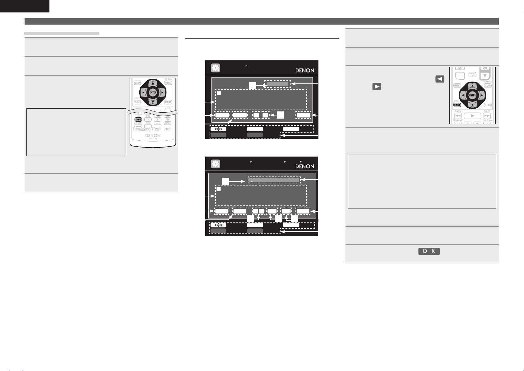
ENGLISH
Inputting characters
Using the cursor buttons
Display the screen for inputting characters
1
(vpage 59 “Menu map”).
Use o p to set the cursor to the character you want
2
to change.
Use ui to change the character,
3
then press ENTER.
• The types of characters that can be input
are as shown below.
GUpper case charactersH
ABCDEFGHIJKLMNOPQRSTUVWXYZ
GLower case charactersH
abcdefghijklmnopqrstuvwxyz
GSymbolsH ! “ # $ % & ‘ ( ) z + , - . / : ; <
= > ? @ [ \ ] ^ _ ` { | } ˜
GNumbersH
• The input character type can be switched by pressing
the display name is being changed.
Repeat steps 2 and 3 to change the name then press
4
ENTER to register it.
0123456789 (Space)
SHIFT while
Keyboard screen
n Display of a keyboard input screen
GRename / Quick Select Name / Zone RenameH
INPUT SETUP
RENAME
w
A
B
D
E
G
C
N
O
P
0
1
e
r
2
$
%
&
Cle ar S pace 0 1 O K
t
a/A Nor malSHI FT SEA RCH
GAccount input / Search by text / Proxy Name /
MANUAL SETUP N ETWORK SET UP OTHER
FRIEND LY NAME ED IT
w
a
b
c
n
o
e
r
p
0
1
2
_
/
:
Cle ar S pace
t
a/A Nor malSHI FT SEA RCH
q Character input section
w Cursor
e Keyboard section
r Clear key
t Space key
y Cursor keys
u OK key
i Guide for operation buttons
o Insert key
Q0 Delete key
F
Q
R
T
S
3
4
6
5
’
(
z
)
Friendly Name EditH
DEN ON:[ AVR-3 311]Edi t
d
e
g
f
q
r
t
s
3
4
6
5
˜
?
\
[
0 1
y o Q0
BDBD
H
I
U
V
7
8
+
,
L
K
J
Y
X
W
”
!
9
=
<
;
y
RET URN C ancelENT ER Inpu tSelect
h
i
u
v
7
8
]
^
Ins Del O K
l
k
j
y
x
w
@
.
9
|
{
ˋ
RET URN C ancelENT ER Inpu tSelect
Display the screen for inputting characters
1
(vpage 59 “Menu map”).
Press SEARCH while a normal screen is displayed.
2
A keyboard screen is displayed.
Select a character to be changed.
3
q
M
Z
#
>
u
i
q
m
z
}
u
i
q Press uio p to select
or .
w Press ENTER to place the
cursor at the character to be
changed.
Each time ENTER is pressed, the
cursor moves by one character.
Select a character to be input with uio p then
4
press ENTER.
• The types of characters that can be input are as shown below.
GUpper case characters/Numbers/SymbolsH
ABCDEFGHIJKLMNOPQRSTUVWXYZ
0123456789
! “ # $ % & ’ ( ) z + , ; < = >
GLower case characters/Numbers/SymbolsH
abcdefghijklmnopqrstuvwxyz
0123456789
. @ - _ / : ˜ ? [ \ ] ^ ` { | }
• The input character type can be switched by pressing
the display name is being changed.
SHIFT while
Repeat steps 3 and 4 to change the name.
5
Use uio p to select , then press ENTER.
6
62
Page 67

ENGLISH
Input Setup
Perform settings related to input source playback.
• You do not have to change the settings to use the unit. Make settings when needed.
Menu operation
Press ZONE SELECT to switch the zone mode to “MAIN”.
1
The “MAIN” indicator lights.
Press AMP to set the remote control unit to amplier operation
2
mode.
Press MENU.
3
The menu is displayed on the TV screen.
Use ui to select the menu to be set or operated.
4
Press ENTER or p to enter the setting.
5
• To return to the previous item, press RETURN.
• Exiting the Menu, press MENU while the menu is displayed.
The menu display disappears.
Important information
n About the display of input sources
In this section, the configurable input sources for each item are shown as follows.
DVD TV SAT/CBL DVR GAME V.AUX DOCK NET/USB TUNER PHONO CD
BD
NOTE
Input sources that have been set to “Delete” at “Source Delete” (vpage82) cannot be selected.
Items that can be set with the Input Setup procedure
Auto Preset (vpage64)
INPUT SE TUP
AUTO PRE SET
Star t
Star t the auto pr eset p rocess
ENTE R Ent er RE TURN Ret urn
Input Assign (vpage64)
INPUT SE TUP
INPUT AS SIGN
Defa ult
[ H DMI ]
BD
DVD
TV
SAT/ CBL
DVR
GAME
V.AU X
Chan ge HDM I input conne ctor a ssignme nt
[ DI GITAL ]
HDMI 1
HDMI 2
None
HDMI 3
HDMI 4
HDMI 5
HDMI 6
None
Coax 1
Opt1
Coax 2
Opt2
None
None
ENTE R Ent erSele ct RETU RN R eturn
Rename (vpage67)
INPUT SE TUP
RENAME
DVD
Defa ult
DVD
Playback Mode (vpage68) : NET/USB
INPUT SE TUP
PLAYBACK MODE
Repe at
Rand om
Dire ct Pla y
OFF
OFF
Favo rite
[ C OMP ]
None
1-RC A
None
2-RC A
None
None
None
RETU RN R eturn
Preset Skip (vpage64) Preset Name (vpage64)
INPUT SE TUP
PRESET S KIP
Bloc k
A B lock Presets
A1 F M 8 7.50MH z
A2 F M 8 9.10MH z
A3 F M 9 8.10MH z
A4 F M 1 08.00M Hz
A5 F M 9 0.10MH z
A6 A M 90.1 0MHz
A7 A M 90.1 0MHz
A8 A M 90.1 0MHz
Chan ge mem ory blo cks
A
ON
ON
ON
ON
ON
ON
ON
ON
ON
Video (vpage65) Input Mode (vpage67)
INPUT SE TUP
VIDEO
Vide o Sele ct
Vide o Mode
Vide o Conv ert
i/p Scaler
Reso lution (Analog )
Reso lution (HDMI)
Prog ressiv e Mode
Aspe ct
Sele ct des ired vi deo in put so urce
Sour ce
Auto
ON
Anal og & H DMI
Auto
Auto
Auto
Full
Source Level (vpage67)
INPUT SE TUP
SOURCE L EVEL
Anal og Inp ut
Digi tal In put
Comp ensate analog audio input playba ck lev el
0 dB
0 dB
Still Picture (vpage68)
INPUT SET UP
STILL PI CTURE
Slid e Show
Inte rval
OFF
5sec
[1/7 ]
RETU RN R eturn
RETU RN R eturn
RETU RN R eturn
INPUT SE TUP
PRESET N AME
Bloc k
A1 F M 8 7.50MH z
A2 F M 8 9.10MH z
A3 F M 9 8.10MH z
A4 F M 1 08.00M Hz
A5 F M 9 0.10MH z
A6 A M 90.1 0MHz
A7 A M 90.1 0MHz
A8 A M 90.1 0MHz
Chan ge mem ory blo cks
INPUT SE TUP
INPUT MO DE
Inpu t Mode
Deco de Mod e
Auto matica lly det ect in put si gnal an d play back
A
[ ]
[ ]
[ ]
[ ]
[ ]
[ ]
[ ]
[ ]
Auto
Auto
[1/7 ]
RETU RN R eturn
RETU RN R eturn
Playback Mode (vpage67) : DOCK
INPUT SE TUP
PLAYBACK MODE
Repe at
Shuf fle
Canc el rep eat mod e
OFF
OFF
RETU RN R eturn
Basic versionSimple version InformationAdvanced version
Remote control operation
buttons
Move the cursor
(Up/Down/Left/Right)
Canc el rep eat mod e
RETU RN R eturn
Disp lay on ly the select ed sti ll pict ure im age
RETU RN R eturn
Confirm the setting Return to previous menu
63
Page 68

ENGLISH
Input Setup
Auto Preset
Use the auto preset function to program radio stations.
Setting items Setting details
Start
Start the auto preset
process.
TUNER
If an FM station cannot be preset automatically, select the desired
station by tuning it in manually, then preset it manually.
Preset Skip Default settings are underlined.
Set preset channel to be skipped when selecting.
Setting items Setting details
A – G
Set the preset channels you
do not want to display. You
can set by preset memory
block (A to G) or by preset
channel (1 to 8).
TUNER
1 – 8 : Set by individual preset channels in the currently selected preset
memory block.
• ON : Display the selected preset channel.
• Skip : Do not display the selected preset channel.
If you set “Block Presets” to “Skip”, you can skip the preset memory
blocks (A to G).
Preset Name
Assign name to a preset memory.
Setting items Setting details
A1 – G8
Select the preset channel.
TUNER
Default
The changed preset name
is returned to the default
setting.
• Up to eight characters can be input.
• For character input, see page 61.
Yes : Reset to the defaults.
No : Do not reset to the defaults.
Input Assign
Examples of input assign menu screen displays
q Input Source
w HDMI input
e Digital audio input
r Component video input
q
INPUT SETUP
INPUT ASSIGN
Def ault
BD
DVD
TV
SAT /CBL
DVR
GAM E
V.A UX
Cha nge HDMI inpu t con nect or as sign ment
[ HDMI ]
HDM I1
HDM I2
Non e
HDM I3
HDM I4
HDM I5
HDM I6
[ D IGIT AL ]
Non e
Coa x1
Opt 1
Coa x2
Opt 2
Non e
Non e
ENT ER EnterSelec t RE TURN Ret urn
ew r
[ COMP ]
Non e
1-R CA
Non e
2-R CA
Non e
Non e
Non e
Input assignments menu operations
Use uio p to move the highlight to the item you want to set.
1
Press ENTER, then use o p to select the input connector to be
2
assigned.
Press ENTER to register the setting.
3
NOTE
If all “HDMI”, “Digital” and “Component” assignment of the Game source are set to “None”, Game
source cannot be selected with the input source selection.
64
Remote control operation
buttons
Move the cursor
(Up/Down/Left/Right)
Confirm the setting Return to previous menu
Page 69

ENGLISH
Input Setup
Setting items Setting details
HDMI
Set this to change the HDMI
input connectors assigned
to the input sources.
BD DVD TV
SAT/CBL
GAME V.AUX DOCK
Digital
Set this to change the digital
input connectors assigned
to the input sources.
BD DVD TV
SAT/CBL
GAME V.AUX DOCK
CD
DVR
DVR
HDMI 1 / HDMI 2 / HDMI 3 / HDMI 4 / HDMI 5 / HDMI 6
None : Do not assign an HDMI input connector to the selected input
source.
• At time of purchase, the settings of the different input sources are as
shown below.
Input
source
Default
setting
• An input source to which an HDMI input connector cannot be assigned
is displayed as “– – –”.
• To play the video signal assigned at “HDMI” combined with the audio
signal assigned at “Input Assign“ – “Digital”, select “Digital” at “Input
Mode” (vpage67).
• The audio signals input from the analog and digital connectors are not
output to the monitor.
• When a control dock for iPod is connected, signals cannot be assigned
to the HDMI connectors.
• When “HDMI Control” (vpage78) is set to “ON”, HDMI input connector
cannot be assigned to “TV”.
COAX1 – 2 (COAXIAL) / OPT1 – 2 (OPTICAL)
None : Do not assign a digital input connector to the selected input source.
• At time of purchase, the settings of the different input sources are as
shown below.
Input source BD DVD TV
Default
setting
Input source GAME V.AUX
Default
setting
BD DVD TV
HDMI 1HDMI
2
None
None None None None
SAT/
DVR GAME V.AUX
CBL
HDMI 3HDMI 4HDMI 5HDMI
None
COAX
1
OPT
1
DOCK
SAT/
CBL
COAX
2
CD
Setting items Setting details
Component
Set this to change the
component video input
connectors assigned to the
input sources.
DOCK
None
6
BD DVD TV
SAT/CBL
GAME V.AUX DOCK
Default
The “Input Assign” settings
are returned to the default
settings.
DVR
1-RCA / 2-RCA (Component video)
None : Do not assign a component video input connector to the selected
input source.
• At time of purchase, the settings of the different input sources are as
shown below.
Input
source
Default
setting
• An input source to which an component video input connector cannot be
assigned is displayed as “– – –”.
• When a control dock for iPod is connected, signals cannot be assigned
to the component video connectors.
Yes : Reset to the defaults.
No : Do not reset to the defaults.
If you select “Default” and press ENTER, the message “Default
Setting?” is displayed. Select “Yes” or “No”, and then press ENTER.
BD DVD TV
None 1-RCA None 2-RCA None None None None
SAT/
DVR GAME V.AUX
CBL
DOCK
Basic versionSimple version InformationAdvanced version
Video Default settings are underlined.
Set the source video.
z “TV” or “GAME” can be set when “HDMI” (vpage65) or “Component” (vpage65) has been
assigned.
DVR
OPT
2
Setting items Setting details
Video Select
Video of another input
source is played back
combined with the playing
audio.
Source : Play the picture and sound of the input source.
BD / DVD / TV / SAT/CBL / DVR / GAME / V.AUX / DOCK : Select video
input source to view. This can be set for individual input sources.
“TV” and “GAME” can be selected only when a component video is
assigned as an input source.
NOTE
• It is not possible to select HDMI input signals.
• Input sources for which “Delete” is selected at “Source Delete”
(vpage82) cannot be selected.
Remote control operation
buttons
Move the cursor
(Up/Down/Left/Right)
Confirm the setting Return to previous menu
65
Page 70

ENGLISH
Input Setup
Setting items Setting details
Video Mode
Make settings for video
processing.
BD DVD TV
SAT/CBL
z
GAME
Video Convert
The input video signal is
converted automatically
in conjunction with the
connected TV (vpage13
“Converting input video
signals for output (Video
conversion function)”).
BD DVD TV
GAME
i/p Scaler
Convert the input source’s
resolution to the resolution
set at “Resolution”.
BD DVD TV
GAME
NET/USB
SAT/CBL
z
SAT/CBL
z
V.AUX DOCK
V.AUX DOCK
V.AUX DOCK
DVR
DVR
DVR
Auto : Process video automatically based on the HDMI content
information.
Movie : Process video normally.
Game : Always process video appropriate for game content.
z
• If “Video Mode” is set to “Auto”, the mode is switched according to the
input contents.
• If a source is played in both MAIN ZONE (audio and video) and ZONE2
(audio only) modes in the same room, audio in MAIN ZONE and ZONE2
modes may sound out of synchronization, but this is not malfunction. In
this case, setting to “Game” mode may improve audio synchronization.
ON : The input video signal is converted.
OFF : The input video signal is not converted.
• When a non-standard video signal from a game machine or some other
source is input, the video conversion function might not operate. In this
case set “Video Convert” to “OFF”.
• When “Video Convert” is set to “OFF”, the video conversion function
z
z
does not work. In this case, connect this unit and TV with the same type
of cable.
Analog : Use i/p scaler function for analog video signal.
Analog & HDMI : Use i/p scaler function for analog and HDMI video signal.
HDMI : Use i/p scaler function for HDMI video signal.
OFF : Do not use i/p scaler function.
• “Analog & HDMI” and “HDMI” can be set for input sources for which an
HDMI input connector is assigned.
• Which items can be set depend on the input source assigned to each
input connector.
• This function is not effective when the input signal is x.v.Color, 3D,
sYCC 601 color, Adobe RGB color, Adobe YCC 601 color or computer
resolution.
Setting items Setting details
Resolution
Set the output resolution.
Resolution (Analog) :
Analog Video
Resolution (HDMI) : HDMI
BD DVD TV
SAT/CBL
z
GAME
NET/USB
Progressive Mode
Set an appropriate
progressive conversion
mode for the source video
signal.
GAME
Aspect
Set the aspect ratio for the
video signals output to the
HDMI.
GAME
NET/USB
z “TV” or “GAME” can be set when “HDMI” (vpage65) or “Component” (vpage65) has been
V.AUX DOCK
BD DVD TV
SAT/CBL
z
V.AUX DOCK
BD DVD TV
SAT/CBL
z
V.AUX DOCK
assigned.
DVR
DVR
DVR
Auto : The number of pixels the TV connected to the HDMI output
connector supports is detected automatically and the appropriate output
resolution is set.
480p / 576p / 1080i / 720p / 1080p / 1080p:24Hz : Set the output resolution.
z
• This item can be set when “i/p Scaler” is set to anything other than
“OFF”.
• When “i/p Scaler” is set to ”Analog & HDMI”, the resolution of both the
analog video input signal and HDMI input signal can be set.
• To watch 1080p/24Hz pictures, use a TV that supports 1080p/24Hz video
signals.
• When set to “1080p/24Hz”, you can enjoy film-like pictures for film
sources (in 24 Hz). For video sources and mixed sources, we recommend
setting the resolution to “1080p”.
• It is not possible to convert a 50 Hz signal into 1080p/24Hz. It is output
at a resolution of 1080p/50Hz.
Auto : The video signal is automatically detected and the appropriate
mode is set.
Video1 : Select mode suitable for video playback
Video2 : Select mode suitable for video and 30-frame film material
playback.
z
z
This item can be set when “i/p Scaler” is set to anything other than
“OFF”.
Full : Output at 16:9 aspect ratio.
Normal : Output at 4:3 aspect ratio.
“Aspect” can be set when “i/p Scaler” is set to anything other than
“OFF”.
66
Remote control operation
buttons
Move the cursor
(Up/Down/Left/Right)
Confirm the setting Return to previous menu
Page 71
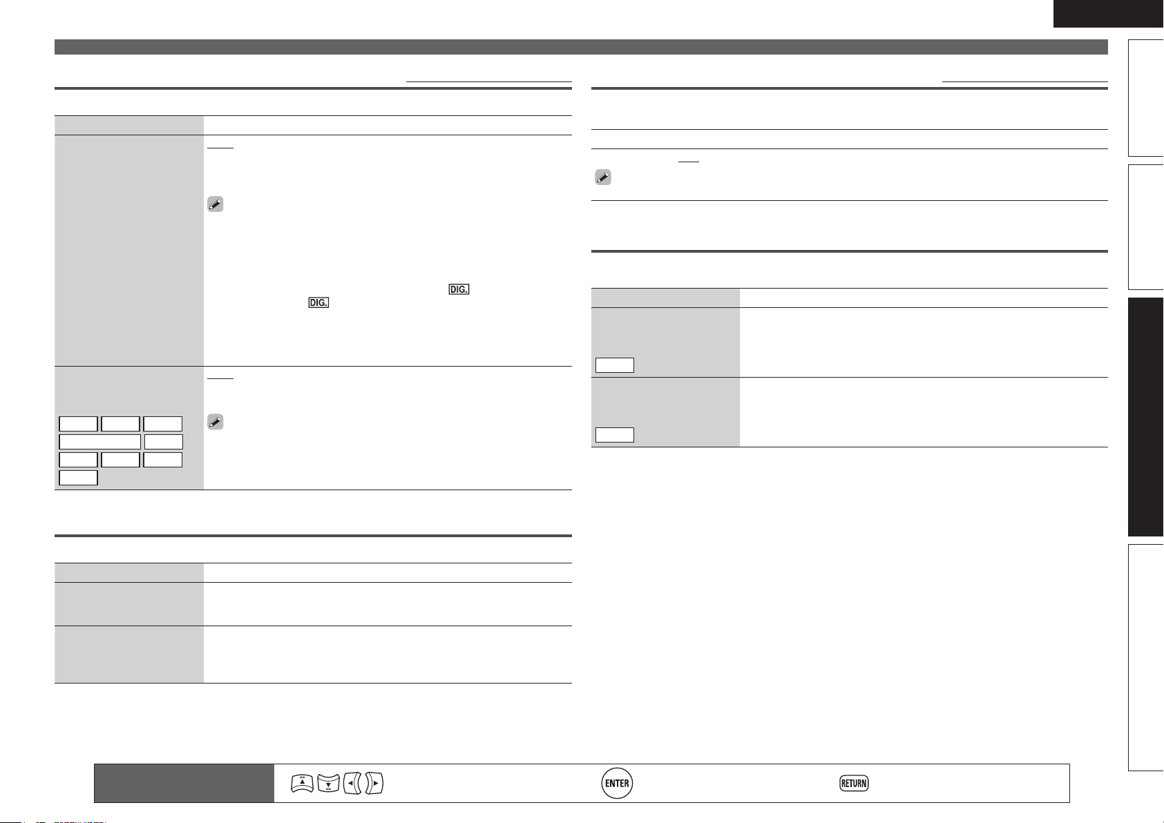
ENGLISH
Input Setup
Input Mode Default settings are underlined.
The input modes available for selection may vary depending on the input source.
Setting items Setting details
Input Mode
Set the audio input modes
for the different input
sources.
Decode Mode
Set the decode mode for
input source.
BD DVD TV
SAT/CBL
DOCK GAME V.AUX
CD
DVR
Auto : Automatically detect input signal and perform playback.
HDMI : Play only signals from HDMI input.
Digital : Play only signals from digital input.
Analog : Play only signals from analog input.
• “HDMI” can be set for input sources for which “HDMI” is assigned at
“Input Assign” (vpage65).
• “Digital” can be set for input sources for which “Digital” is assigned at
“Input Assign” (vpage65).
• If the input source is set to “TV” or “Game”, it cannot be set to “Analog”.
• When digital signals are properly input, the indicator lights on
the display. If the indicator does not light, check the digital input
connector assignment and the connections.
• If “HDMI Control” is set to “ON” and a TV compatible with the ARC is
connected via the HDMI MONITOR connectors, the input mode whose
input source is “TV” is fixed to ARC.
Auto : Detect type of digital input signal and decode and play automatically.
PCM : Decode and play only PCM input signals.
DTS : Decode and play only DTS input signals.
• This item can be set for input sources for which “HDMI” or “Digital” is
assigned at “Input Assign” (vpage64).
• Normally set this mode to “Auto”. Set “PCM” and “DTS” when
inputting the corresponding input signal.
Source Level Default settings are underlined.
• This function corrects the playback level of the selected input source’s audio input.
• Make this setting if there are differences in the input volume levels between the different sources.
Setting details
–12dB – +12dB (0dB)
The analog input level and digital input level can be adjusted independently for input sources for
which “HDMI” or “Digital” is assigned at “Input Assign“ (vpage64).
Playback Mode
n Input source : “DOCK”
Setting items Setting details
Repeat
Make settings for repeat
mode.
DOCK
Shuffle
Make settings for shuffle
mode.
DOCK
All : All files are played repeatedly.
One : A file being played is played repeatedly.
OFF : Repeat playback mode is canceled.
Songs : Shuffle songs.
Albums : Shuffle albums.
OFF : Shuffle playback mode is canceled.
Basic versionSimple version InformationAdvanced version
Rename
Change the display name of the selected input source.
Setting items Setting details
Rename
Change the display name of
the selected input source.
Default
The input source name
is returned to the default
setting.
Remote control operation
buttons
• Up to eight characters can be input.
• For character input, see page 61.
Yes : Reset to the defaults.
No : Do not reset to the defaults.
Move the cursor
(Up/Down/Left/Right)
Confirm the setting Return to previous menu
67
Page 72

ENGLISH
Input Setup
n Input source : “NET/USB”
Setting items Setting details
Repeat
Make settings for repeat
mode.
NET/USB
Random
Make random mode
settings.
NET/USB
Direct Play
DIRECT PLAY on the
Use
sub remote control unit to
set the folder to be played.
NET/USB
All : All files are played repeatedly.
One : A file being played is played repeatedly.
OFF : Repeat playback mode is canceled.
ON : Enable random playback.
OFF : Disable random playback.
Favorites : Play songs registered as “Favorites”.
Music : Play the songs saved on the PC media.
Still Picture Default settings are underlined.
Audio/Video Adjust
The sound being played in the surround mode can be adjusted to your liking.
The items (parameters) that can be adjusted depend on the signal being input and the currently set
surround mode. For details on the adjustable parameters, see “Surround modes and parameters”
(vpage101).
Menu operation
Press ZONE SELECT to switch the zone mode to “MAIN”.
1
The “MAIN” indicator lights.
Press AMP to set the remote control unit to amplier operation
2
mode.
Press MENU.
3
The menu is displayed on the TV screen.
Use ui to select the menu to be set or operated.
4
Press ENTER or p to enter the setting.
5
• To return to the previous item, press RETURN.
• Exiting the Menu, press MENU while the menu is displayed.
The menu display disappears.
Items that can be set with the Audio/Video Adjust procedure
Make settings for playing back still picture images.
Setting items Setting details
Slide Show
Make slide show settings.
NET/USB
Interval
Set the playback time per
image.
NET/USB
68
Remote control operation
buttons
ON : Display still picture images in a slide show.
OFF : Display only the selected still picture image.
5sec – 60sec
Move the cursor
(Up/Down/Left/Right)
Audio Adjust (vpage69)
n Surround Parameter (vpage69)
n Tone (vpage70)
n Audyssey Settings (vpage71)
n A-DSX Soundstage (vpage72)
n Manual EQ (vpage73)
n RESTORER (vpage73)
n Audio Delay (vpage73)
Picture Adjust (vpage74)
Confirm the setting Return to previous menu
Page 73

ENGLISH
Audio/Video Adjust
Audio Adjust
n Surround Parameter
Adjust surround sound parameters. It may not be possible to set this item depending on the input
signal.
Setting items Setting details
Mode
Set the play modes for the
different surround modes.
Cinema EQ
Soften the treble range
of movie soundtracks for
better understanding.
DRC
Compress dynamic range
(difference between loud
and soft sounds).
D.Comp
Compress dynamic range
(difference between loud
and soft sounds).
LFE
Adjust the low-frequency
effects level (LFE).
C.Image
Assign center channel
signal to front left and right
channels for wider sound.
n In the PLgx or PLg mode
Cinema : Surround sound mode optimized for movie sources.
Music : Surround sound mode optimized for music sources.
Game : Surround sound mode optimized for games.
Pro Logic : Dolby Pro Logic playback mode (PLg mode only).
n In the PLgz mode
Height : Dolby PLgz Height playback mode.
n In the DTS NEO:6 mode
Cinema : Surround sound mode optimized for movie sources.
Music : Surround sound mode optimized for music sources.
• When “Surround Parameter” – “F.Height” (vpage69) is set to “ON”,
the “Height” mode is set automatically.
• The “Music” mode is also effective for movie sources including a lot of
stereo music.
ON : “Cinema EQ” is used.
OFF : “Cinema EQ” is not used.
Auto : Automatic dynamic range compression on/off control according to
source. This can be set in the Dolby TrueHD mode.
Low / Mid / High : These set the compression level.
OFF : Dynamic range compression always off.
Low / Mid / High : These set the compression level.
OFF : Turn dynamic range compression off.
–10dB – 0dB
For proper playback of the different sources, we recommend setting
to the values below.
• Dolby Digital sources : “0dB”
• DTS movie sources : “0dB”
• DTS music sources : “–10dB”
0.0 – 1.0 (0.3)
Default settings are underlined.
Setting items Setting details
Panorama
Assign front L/R signal also
to surround channels for
wider sound.
Dimension
Shift sound image center
to front or rear to adjust
playback balance.
C.Width
Assign center channel
signal to front left and right
channels for wider sound.
Delay Time
Adjust delay time to control
sound stage size.
Effect Lev.
Adjust effect signal level.
Room Size
Determine size of acoustic
environment.
ON : Set.
OFF : Do not set.
0 – 6 (3)
0 – 7 (3)
0ms – 300ms (30ms)
1 – 15 (10)
Set to a lower level if the positioning and sense of phase of the
surround signals seems unnatural.
Small : Simulate acoustics of a small room.
Medium-S : Simulate acoustics of a medium-small room.
Medium : Simulate acoustics of a medium room.
Medium-L : Simulate acoustics of a medium-large room.
Large : Simulate acoustics of a large room.
NOTE
“Room Size” does not indicate the size of the room in which sources are
played.
F.Height
Determine whether to use
front height channel.
ON : Audio is output from the front height speaker.
OFF : Audio is not output from the front height speaker.
NOTE
• “F.Height” is displayed with the settings listed below.
• When “Amp Assign” (vpage75) is set to “Normal”.
• When the “Speaker Config.” – “F.Height” setting (vpage75) is set to
other than “None”.
• “F.Height” cannot be set if the HD Audio source being played includes a
front height channel. In this case, the Front height channel is played back
without decoding in PLgz mode, using the input signal.
Basic versionSimple version InformationAdvanced version
Remote control operation
buttons
Move the cursor
(Up/Down/Left/Right)
Confirm the setting Return to previous menu
69
Page 74

ENGLISH
Audio/Video Adjust
Setting items Setting details
Height Gain
Control the front height
channel volume.
Low : Reduce the front height channel volume.
Mid : Front height channel sound is output with standard sound volume.
High : Increase the front height channel volume.
NOTE
“Height Gain” is displayed for the following settings.
• When “Amp Assign” (vpage75) is set to “Normal”.
• When the “Speaker Config.” – “F.Height” setting (vpage75) is set
other than to “None”.
• When surround mode is “PLgz” or the PLgz decoder is used.
AFDM
(Auto flag detect mode)
Detect the source’s
surround back channel
signal and set the
optimum surround mode
automatically.
S.Back
Sets the method of
generating of the surround
back channel.
ON : Set.
OFF : Do not set.
[Example] Playing Dolby Digital software (with EX flag)
• When “AFDM” is set to “ON”, the surround mode is automatically set
to the DOLBY D + PLgx C mode.
• To play in the DOLBY DIGITAL EX mode, set “AFDM” to “OFF” and
“Surround Parameter” – “S.Back” to “MTRX ON”.
Some Dolby Digital EX sources do not include EX flags. If the playback
mode does not switch automatically even when “AFDM” is set to
“ON”, set “Surround Parameter” – “S.Back” to “MTRX ON” or
“PLgx C”.
n For 2-channel sources
ON : The surround back channel is used.
OFF : No signal is played from the surround back channels.
n For multi-channel sources
Set the decoding method for the surround back channel.
DSCRT ON : Play the surround back signals included in the 7.1-channel
source.
MTRX ON : Generate and play the surround back signals from the
surround channel signals.
ES MTRXz1 : Generate and play the surround back signals from the
surround channel signals of the DTS source.
ES DSCRTz2 : Play the surround back signals included in the
6.1-channel DTS source.
PLgx Cz3 : Generate and play the surround back signals by decoding
the signals in the Dolby Pro Logic gx Cinema mode.
PLgx M : Generate and play the surround back signals by decoding the
signals in the Dolby Pro Logic gx Music mode.
OFF : Do not play the surround back channel.
z1 This can be selected when playing DTS sources.
z2 This can be selected when playing DTS sources including a signal to
identify discrete 6.1-channel signals.
z3 This can be selected when “Speaker Config.” – “S.Back” (vpage75)
is set to “2spkrs”.
Setting items Setting details
S.Back
(Continued)
• This can also be set by pressing STANDARD.
• If the source being played contains a surround
back signal, the decoder type is automatically
selected by the AFDM function. Set “AFDM” to
“OFF” to switch to your preferred decoder.
NOTE
If the setting in “Speaker Config.” – “S.Back”
(vpage75) is “None”, “S.Back” is not displayed.
Speaker
Make settings for the
speakers outputting sound
when playing back in
DENON original surround
mode.
Subwoofer
Turn subwoofer output on
and off.
Default
The “Surround Parameter”
settings are returned to the
default settings.
S.Back : Sound is output from the surround back speakers.
F.Wide : Sound is output from the front wide speakers.
F.Height : Sound is output from the front height speakers.
OFF : Sound is not output from the surround back speakers, front wide
speakers, and front height speakers.
NOTE
Only speakers that are set to something other than “None” in “Speaker
Config.” (vpage75) can be selected.
ON : The subwoofer is used.
OFF : The subwoofer is not used.
NOTE
This can be set when the surround mode is “DIRECT” (vpage 42),
“PURE DIRECT” (vpage42) and the “Subwoofer Mode” (vpage76) is
“LFE+Main”.
Yes : Reset to the defaults.
No : Do not reset to the defaults.
n Tone
Adjust the tonal quality of the sound.
Setting items Setting details
Tone Control
Set the tone control function
to ON and OFF.
ON : Allow tone adjustment (bass, treble).
OFF : Playback without tone adjustment.
“Tone Control” can be set when “Dynamic EQ” (vpage71) is set to
“OFF”.
NOTE
• “Tone Control” settings are not reflected to ZONE2 and ZONE3.
• The tone cannot be adjusted in the direct mode.
70
Remote control operation
buttons
Move the cursor
(Up/Down/Left/Right)
Confirm the setting Return to previous menu
Page 75

ENGLISH
Audio/Video Adjust
Setting items Setting details
Bass
Adjust low frequency range
(bass).
Treble
Adjust high frequency range
(treble).
n Audyssey Settings
Set MultEQ® XT, Dynamic EQ® and Dynamic Volume®. These can be selected after Audyssey® Auto
Setup has been performed. For additional information on Audyssey technology, please see page 106.
–6dB – +6dB
“Bass” can be set when “Tone Control” is set to “ON”.
–6dB – +6dB
“Treble” can be set when “Tone Control” is set to “ON”.
Default settings are underlined.
NOTE
If you have not performed Auto Setup, or if you change the speaker settings after performing Auto Setup,
you may not be able to select Dynamic EQ/Dynamic Volume, and “Run Audyssey” may be displayed.
In this case, either perform Audyssey Auto Setup over again or perform “Restore” (vpage10) to return to
the settings after Audyssey Auto Setup was run.
Setting items Setting details
MultEQ XT
Select one equalizer from
three modes. MultEQ XT
corrects both time and
frequency response
problems in the listening
area based on Audyssey
Auto Setup calibration. We
recommend “Audyssey”.
MultEQ XT is the
prerequisite function for
Dynamic EQ and Dynamic
Volume.
Audyssey : Optimize the frequency response of all speakers.
Audyssey Byp.L/R : Optimize frequency response of speakers except
front L and R speakers.
Audyssey Flat : Optimize frequency response of all speakers to flat
response.
Manual : Apply frequency response set with “Manual EQ” (vpage73).
OFF : Turn “MultEQ XT” equalizer off.
• “Audyssey”, “Audyssey Byp. L/R” and “Audyssey Flat” can be
selected after Audyssey Auto Setup has been performed. “Audyssey”
is automatically selected after performing Audyssey Auto Setup. When
“Audyssey”, “Audyssey Byp. L/R” or “Audyssey Flat” is selected,
illuminates.
• After running Audyssey Auto Setup, if the
Speaker Configuration, Distance, Channel
Level, and Crossover Frequency have changed
without increasing the number of speakers
measured, only
• Pressing MULTEQ makes this setting.
illuminates.
NOTE
• “MultEQ XT” and “Manual” cannot be selected when “EQ Customize”
is set to “Not Used” (vpage79).
• When using headphones, “MultEQ XT” is automatically set to “OFF”.
Setting items Setting details
Dynamic EQ
Solve the problem of
deteriorating sound quality
as volume is decreased
by taking into account
human perception and
room acoustics. Works with
MultEQ XT.
Reference Level Offset
Audyssey Dynamic EQ is
referenced to the standard
film mix level. It makes
adjustments to maintain
the reference response
and surround envelopment
when the volume is turned
down from 0 dB. However,
film reference level is not
always used in music or
other non-film content.
Dynamic EQ Reference
Level Offset provides three
offsets from the film level
reference (5 dB, 10 dB, and
15 dB) that can be selected
when the mix level of the
content is not within the
standard.
®
ON : Use Dynamic EQ.
OFF : Do not use Dynamic EQ.
• is displayed when set to “ON”.
• Buttons on the remote control unit or main unit
can be used for operations.
Press DYN EQ/VOL.
Each time DYN EQ/VOL is pressed, the setting is
changed as shown below.
Dynamic EQ : ON
Dynamic Volume : Midnight
Dynamic EQ : OFF
Dynamic Volume : OFF
0dB (Film Ref) : This is the default setting and should be used when
listening to movies.
5dB : Select this setting for content that has a very wide dynamic range,
such as classical music.
10dB : Select this setting for jazz or other music that has a wider dynamic
range. This setting should also be selected for TV content as that is usually
mixed at 10 dB below film reference.
15dB : Select this setting for pop/rock music or other program material
that is mixed at very high listening levels and has a compressed dynamic
range.
Setting is enabled when “Dynamic EQ” is “ON” (vpage71).
Dynamic EQ : ON
Dynamic Volume : OFF
Basic versionSimple version InformationAdvanced version
Dynamic EQ : ON
Dynamic Volume : Evening
Dynamic EQ : ON
Dynamic Volume : Day
Remote control operation
buttons
Move the cursor
(Up/Down/Left/Right)
Confirm the setting Return to previous menu
71
Page 76

ENGLISH
Audio/Video Adjust
Setting items Setting details
Dynamic Volume
Solve the problem of large
variations in volume level
between TV, movies and
other content (between
quiet passages and
loud passages, etc.) by
automatically adjusting to
the user’s preferred volume
setting.
®
Midnight : Most adjustment to softest and loudest sounds.
Evening : Medium adjustment to loudest and softest sound.
Day : Least adjustment to loudest and softest sounds.
OFF : Do not use the “Dynamic Volume”.
• is displayed when set to “ON”.
• If “Dynamic Volume” is set to “Yes” in Auto
Setup (vpage 9), the setting is automatically
changed to “Evening”.
• Buttons on the remote control unit or main unit
can be used for operations.
Press DYN EQ/VOL.
Each time DYN EQ/VOL is pressed, the setting is
changed as shown below.
Dynamic EQ : ON
Dynamic Volume : Midnight
Dynamic EQ : OFF
Dynamic Volume : OFF
Dynamic EQ : ON
Dynamic Volume : OFF
Dynamic EQ : ON
Dynamic Volume : Evening
Dynamic EQ : ON
Dynamic Volume : Day
n A-DSX Soundstage
Adjust Audyssey DSX™ setting and sound stage parameters.
Setting items Setting details
Audyssey DSX
Provides more immersive
surround sound by adding
the new channels.
Stage Width
Adjust sound stage width
when using front wide
speakers.
Stage Height
Adjust sound stage height
when using front height
speakers.
ON-Height- : Turn on A-DSX processing for height
expansion.
ON-Wide- : Turn on A-DSX processing for wide
expansion.
OFF : Do not set Audyssey DSX.
• This can also be set by pressing A-DSX on the
remote control unit or press AUDYSSEY DSX on
the main unit.
• The indicator illuminates on the display.
Audyssey DSX : ON -Height-
OFF Audyssey DSX : ON -Wide-
–10 – +10 (0)
–10 – +10 (0)
• “Audyssey DSX” can be set when you are using front height speakers
or front wide speakers.
• “Audyssey DSX” is only valid when using a center speaker.
• “Audyssey DSX” is valid when surround mode is STANDARD mode
other than PLgz Height.
• “A-DSX Soundstage” cannot be configured if the HD Audio source being
played includes Front height and Front wide channels. In this case, the
respective channels are played back using the input signals.
About Audyssey Dynamic Surround Expansion (A-DSX)
Audyssey DSX is a scalable surround expansion system that adds
new channels to improve the surround impression. Based on research
in human hearing Audyssey DSX adds a pair of Wide channels in the
front because that information is critical in the rendering of a realistic
soundstage.
Audyssey DSX then adds a pair of Height channels above the main
front channels to reproduce the next most important acoustical and
perceptual cues related to soundstage depth. In addition to creating
these new channels, Audyssey DSX applies Surround Envelopment
Processing to enhance the blend between the front and side/back
surround channels. The result is a much more seamless and enveloping
home theater experience.
Default settings are underlined.
72
Remote control operation
buttons
Move the cursor
(Up/Down/Left/Right)
Confirm the setting Return to previous menu
Page 77

ENGLISH
OFF Mode 1
Mode 2
Audio/Video Adjust
n Manual EQ
Use the graphic equalizer to adjust the tone of each speaker.
“Manual EQ” can be set when “MultEQ XT” setting (vpage71) is “Manual”
Setting items Setting details
Adjust CH
Correct the tone of each
speaker.
Base Curve Copy
Copy “Audyssey Flat” curve
from MultEQ® XT.
Default
The “Manual EQ” settings
are returned to the default
settings.
q Select the speaker tone adjustment method.
All : Adjust the tone of all speakers together.
L/R : Adjust the tone of left and right speakers together.
Each : Adjust the tone of each speaker.
w Select the speaker.
e Select the adjustment frequency band.
63Hz / 125Hz / 250Hz / 500Hz / 1kHz / 2kHz / 4kHz / 8kHz / 16kHz
• Select the speakers you want to adjust when “L/R” or “Each” is
selected.
r Adjust the level.
–20.0dB – +6.0dB (0.0dB)
Yes : Copy.
No : Do not copy.
“Base Curve Copy” is displayed after Audyssey® Auto Setup has
been performed.
Yes : Reset to the defaults.
No : Do not reset to the defaults.
Default settings are underlined.
n RESTORER
Compressed audio formats such as MP3, WMA (Windows Media Audio) and MPEG-4 AAC reduce
the amount of data by eliminating signal components that are hard for the human ear to hear. The
RESTORER function generates the signals eliminated upon compression, restoring the sound to
conditions near those of the original sound before compression. It also corrects the sense of volume of
the bass to obtain richer sound with compressed audio signals.
Setting details
OFF : Do not use RESTORER.
Mode1 (RESTORER 64) : Optimized mode for compressed sources with very weak highs.
Mode2 (RESTORER 96) : Apply suitable bass and treble boost for all compressed sources.
Mode3 (RESTORER HQ) : Optimized mode for compressed sources with normal highs.
• This item can be set with analog signals or when a PCM signal (fs = 44.1/48
kHz) is input.
• This cannot be set when the surround mode is set to “DIRECT” or “PURE
DIRECT”.
• This item default setting for “iPod” and “NET/USB” is “Mode3”. All others are
set to “OFF”.
• When set to something other than “OFF”,
• Pressing RESTORER on the remote control unit or the main unit makes this
setting.
(RESTORER 64)
Mode 3
(RESTORER HQ)
is displayed.
(RESTORER 96)
Basic versionSimple version InformationAdvanced version
Remote control operation
buttons
Move the cursor
(Up/Down/Left/Right)
n Audio Delay
While viewing video, manually adjust the time to delay audio output.
Setting details
0ms – 200ms
• This item can be set within the range of 0 to 100 ms when “Auto Lip Sync” is set to “ON” and when
a TV compatible with Auto Lip Sync is connected.
• Store “Audio Delay” for each input source.
• Audio Delay for game mode can be set when “Video Mode” (vpage66) is set to “Auto” or “Game”.
Confirm the setting Return to previous menu
Default settings are underlined.
73
Page 78

ENGLISH
Audio/Video Adjust
Picture Adjust Default settings are underlined.
• This item can be set when the input source is
DOCK NET/USB
.
• With input sources other than the ones above, this item can be set when “Video Select” is selected. In
this case, the original input source settings are called out.
• Can be set when the “Video Convert” setting (vpage66) is “ON”.
• “TV” or “GAME” can be set when “HDMI” (vpage65) or “Component” (vpage65) has been assigned.
Setting items Setting details
Contrast
–6 – +6 (0)
Adjust picture contrast.
Brightness
0 – +12
Adjust picture brightness.
Chroma Level
–6 – +6 (0)
Adjust picture chroma level
(saturation).
Hue
–6 – +6 (0)
Adjust color hue.
DNR
OFF / Low / Mid / High
Reduce overall picture
noise.
Enhancer
0 – +12
Emphasize picture contours.
BD DVD TV SAT/CBL DVR GAME V.AUX
Manual Setup
Set when changing Audyssey® Auto Setup settings, or when changing the audio, video, display
or other settings.
• If you change the speaker settings after performing Audyssey Auto Setup, it will not be possible
to set MultEQ® XT, Dynamic EQ® and Dynamic Volume® (vpage71, 72).
• Can be used without changing the settings. Please set if necessary.
Menu operation
Press ZONE SELECT to switch the zone mode to “MAIN”.
1
The “MAIN” indicator lights.
Press AMP to set the remote control unit to amplier operation
2
mode.
Press MENU.
3
The menu is displayed on the TV screen.
Press ui to select the menu to be set or operated.
4
Press ENTER or p to enter the setting.
5
• To return to the previous item, press RETURN.
• Exiting the Menu, press MENU while the menu is displayed.
The menu display disappears.
• “DNR” and “Enhancer” are each effective with HDMI output.
• The value set at “Picture Adjust” is stored in the memory individually for each input source.
74
Remote control operation
buttons
Move the cursor
(Up/Down/Left/Right)
Items that can be set with the Manual Setup procedure
Speaker Setup (vpage75)
MANUAL S ETUP
SPEAKER SETUP
Amp Assign
Spea ker Co nfig.
Bass Setti ng
Dist ance
Chan nel Le vel
Cros sover Frequen cy
Fron t Spea ker Set up
Assi gn sur round b ack AM P for other u se
MANUAL SE TUP
NETWORK S ETUP
Netw ork Co nnectin g
Othe r
Naps ter Ac count
Last .fm Ac count
Last .fm Di splay
Netw ork In formati on
Make setti ngs for wired LAN
Confirm the setting Return to previous menu
HDMI Setup (vpage77) Audio Setup (vpage78)
MANUAL S ETUP
HDMI SET UP
RGB Range
Auto Lip S ync
HDMI Audio Out
Moni tor Ou t
HDMI Contr ol
Use video range f rom 16 (blac k) to 2 35 (wh ite)
Norm al
ON
AMP
Moni tor 1
OFF
RETU RN R eturn
Zone Setup (vpage81)Network Setup (vpage79) Option Setup (vpage82)
MANUAL S ETUP
ZONE SET UP
ZONE 2 Setu p
ZONE 3 Setu p
Make setti ngs for audio playb ack in a ZONE 2
RETU RN R eturn
MANUAL S ETUP
AUDIO SE TUP
2ch Direct /Stereo
Auto Surro und Mod e
EQ C ustomi ze
Make vario us sett ings f or 2ch mode p laybac k
MANUAL S ETUP
OPTION S ETUP
Volu me Con trol
Sour ce Del ete
GUI
Remo te Pre set Cod es
Quic k Sele ct Name
Zone Renam e
Trig ger Ou t
Remo te ID Setup
Make setti ngs for volum e cont rol
Page 79

ENGLISH
Manual Setup
Speaker Setup Default settings are underlined.
Perform when setting the speakers manually or when changing settings made in Audyssey Auto Setup.
• If you change the speaker settings after performing Audyssey Auto Setup, it will not be possible to select
MultEQ XT, Dynamic EQ and Dynamic Volume (vpage71, 72).
• Manual Setup can be used without changing the settings. Please set if necessary.
Setting items Setting details
Amp Assign
Set the speakers connected
to this unit.
Speaker Config.
Select speaker configuration
and size (bass reproduction
capability).
NOTE
Do not use the outward
shape of the speaker to
determine selection of a
“Large” or “Small” speaker.
Instead, use the frequencies
set in “Crossover
Frequency” (vpage77) as
the standard for determining
bass reproduction capability.
Normal : Set when using surround back, front height or front wide
speakers.
ZONE2 : Set for connecting the speakers for ZONE2 to the SURR.BACK/
AMP ASSIGN terminals.
ZONE3 : Set for connecting the speakers for ZONE3 to the SURR.BACK/
AMP ASSIGN terminals.
ZONE2/3-MONO : Set to output the ZONE2 and ZONE3 sound in
monaural, and to output the L side of the SURR.BACK/AMP ASSIGN
terminal from ZONE2, and the R side from ZONE3.
Bi-Amp : Set for connecting a tweeter of a front speaker to the SURR.
BACK/AMP ASSIGN terminals and a woofer of a front speaker to the
FRONT terminals.
2CH : Set for 2-channel direct/stereo playback. When “2CH” is set,
connect the second set of front speakers to the SURR.BACK/AMP
ASSIGN terminals.
Front B : Set for connecting the second front speakers to the SURR.
BACK/AMP ASSIGN terminals. In this case, make settings for “Front
Speaker Setup” (vpage77).
Front : Set the front speaker size.
• Large : Use a large speaker that can adequately play back low
frequencies.
• Small : Use a small speaker that has inadequate playback capacity for
low frequencies.
• When “Subwoofer” is set to “No”, “Front” is automatically set to
“Large”.
• When “Front” is set to “Small”, “Center”, “Surround“, “S.Back”,
“F.Height” and “F.Wide” can not be set to “Large”.
Center : Set the presence and size of the center speaker.
• Large : Use a large speaker that can adequately play back low
frequencies.
• Small : Use a small speaker that has inadequate playback capacity for
low frequencies.
• None : Select when a center speaker is not connected.
“Large” is not displayed when “Front” is set to “Small”.
Setting items Setting details
Speaker Config.
(Continued)
Subwoofer : Set the presence of a subwoofer.
• Yes : Use a subwoofer.
• No : Select when a subwoofer is not connected.
When “Front” is set to “Small”, “Subwoofer” is automatically set to
“Yes”.
Surround : Set the presence and size of the surround speakers.
• Large : Use a large speaker that can adequately play back low
frequencies.
• Small : Use a small speaker that has inadequate playback capacity for
low frequencies.
• None : Select when the surround speakers are not connected.
• When “Surround” is set to “Large”, “S.Back”, “F.Height” and “F.Wide”
can be set to “Large”.
• When “Surround” is set to “None”, “S.Back”, “F.Height” and “F.Wide”
can automatically set to “None”.
S.Back : Set the presence, size and number of surround back speakers.
• Large : Use a large speaker that can adequately play back low
frequencies.
• Small : Use a small speaker that has inadequate playback capacity for
low frequencies.
• None : Select when the surround back speakers are not connected.
• 2spkrs : Use two surround back speakers.
• 1spkr : Use only one surround back speaker. When you select this
setting, connect the surround back speaker to the left (L) channel.
Even when the “S.Back“ setting is other than “None”, sound may
not be emitted from the surround back speaker, depending on the
playback source. In this case, make “Surround Parameter” – “S.Back”
setting other than “OFF” (vpage70).
NOTE
When “Amp Assign” setting (vpage75) is other than “Normal”, you
cannot make the “S.Back” setting.
F.Height : Set the presence and size of the front height speakers.
• Large : Use a large speaker that can adequately play back low
frequencies.
• Small : Use a small speaker that has inadequate playback capacity for
low frequencies.
• None : Select when the front height speakers are not connected.
NOTE
When “Amp Assign” setting (vpage75) is other than “Normal”, you
cannot make the “F.Height” setting.
Basic versionSimple version InformationAdvanced version
Remote control operation
buttons
Move the cursor
(Up/Down/Left/Right)
Confirm the setting Return to previous menu
75
Page 80

ENGLISH
Manual Setup
Setting items Setting details
Speaker Config.
(Continued)
F.Wide : Set the presence and size of the front wide speakers.
• Large : Use a large speaker that can adequately play back low
frequencies.
• Small : Use a small speaker that has inadequate playback capacity for
low frequencies.
• None : Select when the front wide speakers are not connected.
NOTE
When “Amp Assign” setting (vpage75) is other than “Normal”, you
cannot make the “F.Wide” setting.
Bass Setting
Set subwoofer and LFE
signal range playback.
Subwoofer Mode : Select low range signals to be reproduced by
subwoofer.
• LFE : The low range signal of the channel set to “Small” speaker size is
added to the LFE signal output from the subwoofer.
• LFE+Main : The low range signal of all channels is added to the LFE
signal output from the subwoofer.
• “Subwoofer Mode” can be set when “Speaker Config.” – “Subwoofer”
(vpage75) is set to “Yes”.
• Play music or a movie source and select the mode offering the strongest
bass.
• Select “LFE+Main” if you want the bass signals to always be produced
from the subwoofer.
NOTE
If “Front” and “Center” for “Speaker Config.” are set to “Large”, and
“Subwoofer Mode” is set to “LFE”, no sound may be output from the
subwoofers, depending on the input signal or selected surround mode.
LPF for LFE : Set LFE signal playback range.
• 80Hz / 90Hz / 100Hz / 110Hz / 120Hz / 150Hz / 200Hz / 250Hz
Distance
Set distance from listening
position to speakers.
Measure beforehand the
distance from the listening
position to each speaker.
Unit : Set the unit of distance.
• Meters / Feet
Step : Set the minimum variable width of the distance.
• 0.1m / 0.01m
• 1ft / 0.1ft
Front L / Front R / Center / Subwoofer / Surround L / Surround R /
S.Back L
: Select the speaker.
• 0.00m – 18.00m / 0.0ft – 60.0ft : Set the distance.
z
/ S.Back Rz / F.Height L / F.Height R / F.Wide L / F.Wide R
z When the “Speaker Config.” – “S.Back” setting (vpage75) is set to
“1spkr”, “S.Back” is displayed.
Setting items Setting details
Distance
(Continued)
• The speakers that can be selected differ depending on the “Amp Assign”
(vpage75) and “Speaker Config.” (vpage75) settings.
• Default settings :
Front L / Front R / Center / Subwoofer / F.Height L / F.Height R / F.Wide L /
F.Wide R : 3.6 m (12.0 ft)
Surround L / Surround R / S.Back L / S.Back R : 3.0 m (10.0 ft)
• Set the difference in the distance between the speakers to less than
6.0 m (20 ft).
NOTE
Speakers set to “None” in “Speaker Config.” (vpage75) are not displayed.
Default : The “Distance” settings are returned to the default settings.
• Yes : Reset to the defaults.
• No : Do not reset to the defaults.
When you select “Default” and press ENTER, the “Default Setting?”
prompt is displayed. Select either “Yes” or “No”, and press ENTER.
Channel Level
Set the volume of the test
tone to be the same when it
is output from each speaker.
Test Tone Start : Output test tone.
• Front L / F.Height L / Center / F.Height R / Front R / F.Wide R /
Surround R / S.Back Rz / S.Back Lz / Surround L / F.Wide L /
Subwoofer : Select the speaker.
z When the “Speaker Config.” – “S.Back” setting (vpage75) is set to
“1spkr”, “S.Back” is displayed.
• –12.0dB – +12.0dB (0.0dB) : Adjust the volume.
• When o is pressed while the subwoofer volume is set to “–12 dB”, the
“Subwoofer” setting switches to “OFF”.
• When “Channel Level” is adjusted, the adjusted values are set for all the
surround modes. To adjust the channel level separately for the different
surround modes, use the operation see page 51.
NOTE
• Speakers set to “None” in the “Speaker Config.” (vpage75) settings
are not displayed.
• When a headphones jack is inserted in the PHONES jack of this unit, the
“Channel Level” is not displayed.
Default : The “Channel Level” settings are returned to the default settings.
• Yes : Reset to the defaults.
• No : Do not reset to the defaults.
When you select “Default” and press ENTER, the “Default Setting?”
prompt is displayed. Select either “Yes” or “No”, and press ENTER.
76
Remote control operation
buttons
Move the cursor
(Up/Down/Left/Right)
Confirm the setting Return to previous menu
Page 81

ENGLISH
Manual Setup
Setting items Setting details
Crossover Frequency
Set the maximum frequency
of the bass signal output
from each channel to
the subwoofer. Set the
Crossover Frequency to
suit the bass reproduction
capability of the speaker
being used.
Front Speaker Setup
Set the front speakers to
use for every surround
mode.
NOTE
This can be set when “Amp
Assign” is set to “Front B”
(vpage75).
Crossover : Set the crossover frequency.
• 40Hz / 60Hz / 80Hz / 90Hz / 100Hz / 110Hz / 120Hz / 150Hz / 200Hz /
250Hz
Advanced : Specify crossover frequency for each speaker.
• Front / Center / Surround / S.Back / F.Height / F.Wide : Select the
speaker.
• 40Hz / 60Hz / 80Hz / 90Hz / 100Hz / 110Hz / 120Hz / 150Hz / 200Hz /
250Hz : Set the crossover frequency.
• “Crossover Frequency” can be set when the “Bass Setting” –
“Subwoofer Mode” (vpage76) setting is “LFE+Main”, or when you
have a speaker that is set to “Small”.
• Always set the crossover frequency to “80Hz”. When using small
speakers, however, we recommend setting the crossover frequency to
a higher frequency.
• For speakers set to “Small”, sound below the crossover frequency
is cut from the sound output. The cut bass sound is output from the
subwoofer or front speakers.
• The speakers that can be set when “Advanced” is selected differ
depending on to the “Subwoofer Mode” setting (vpage76).
• When “LFE” is selected, speakers set to “Small” at “Speaker Config.”
can be set. If the speakers are set to “Large”, “Full Band” is displayed
and the setting cannot be made.
• If set to “LFE+Main”, this setting can be made regardless of the
speaker size.
2CH DIRECT/STEREO : The front speakers used in the direct, stereo and
pure direct play modes (2 channel) are set in advance.
• A : Front speaker A is used.
• B : Front speaker B is used.
• A+B : Both front speakers A and B are used.
MULTI CH : The front speakers used in modes other than the direct,
stereo and pure direct play modes (2 channel) are set in advance.
• A : Front speaker A is used.
• B : Front speaker B is used.
• A+B : Both front speakers A and B are used.
HDMI Setup Default settings are underlined.
Make settings for HDMI video/audio output.
Setting items Setting details
RGB Range
Set the video range of RGB
output from the HDMI
connector.
Auto Lip Sync
Make automatic
compensation for timing
shift in audio and video
output.
HDMI Audio Out
Select HDMI audio output
device.
Monitor Out
Make settings for HDMI
monitor output.
Normal : Output with RGB video range (16 (black) to 235 (white)).
Enhanced : Output with RGB video range (0 (black) to 255 (white)).
This setting is active when using a TV equipped with a DVI terminal.
ON : Compensated.
OFF : Not compensated.
AMP : Play back through speakers connected to the receiver.
TV : Play back through TV connected to the receiver.
When the HDMI control function is activated, priority is given to the TV
audio setting (vpage50 “HDMI control function”).
Monitor 1 : A TV connected to the MONITOR 1 terminal is always used.
Monitor 2 : A TV connected to the MONITOR 2 terminal is always used.
• With “Resolution” (vpage66) not set to “Auto”,
check whether the TV you are using is compatible
with the resolution under “HDMI Information”
– “HDMI Monitor 1 Information” and “HDMI
Monitor 2 Information” (vpage86).
• You can also set “Monitor Out” by pressing
MONITOR SELECT.
Basic versionSimple version InformationAdvanced version
Remote control operation
buttons
Move the cursor
(Up/Down/Left/Right)
Confirm the setting Return to previous menu
77
Page 82

ENGLISH
Manual Setup
Setting items Setting details
HDMI Control
You can link operations with
devices connected to HDMI
and compatible with HDMI
Control.
ON : Use HDMI control function.
OFF : Do not use HDMI control function.
• When a device that is not compatible with the HDMI control function is
connected, set “HDMI Control” to “OFF”.
• Please consult the operating instructions for each connected component
to check the settings.
• Refer to “HDMI control function” (vpage50) for more information about
the HDMI control function.
NOTE
• When “HDMI Control” is set to “ON”, it consumes more standby
power. If you are not using this unit for an extended period, it is
recommended that you unplug the power cord from the power outlet.
• “HDMI Control” does not work when the power to the equipment is off.
Either turn power on or set to standby.
• The HDMI control function controls operations of a TV that is compatible
with the HDMI control function. Make sure that the TV and HDMI are
connected when you perform HDMI control.
• If the “HDMI Control” settings have been changed, always reset the
power to connected devices after the change.
Standby Source
Sets the HDMI input source
to put into standby when
the power is on.
Power Off Control
Links the power standby
of this unit to external
equipment.
Last : This item is set at the last-used input source.
HDMI1 / HDMI2 / HDMI3 / HDMI4 / HDMI5 / HDMI6 : Put the respective
input source into standby.
“Standby Source” can be set when “HDMI Control” is set to “ON”.
All : If power to a connected TV is turned off independently of the input
source, power to this unit is automatically set to standby.
Video : If power to a connected TV is turned off when the input source is
BD / DVD / TV / SAT/CBL / DVR / GAME / V.AUX / DOCK, power to this unit
is automatically set to standby.
OFF : This unit does not link with power to a TV.
“Power Off Control” can be set when “HDMI Control” is set to “ON”.
Audio Setup Default settings are underlined.
Make settings for audio playback.
Setting items Setting details
2ch Direct/Stereo
Select the method for
setting the speakers used
in the 2-channel direct and
stereo playback modes.
Setting : Select the method for setting the speakers used in the 2-channel
direct and stereo playback modes.
• Basic : The settings at “Speaker Setup” (vpage75) are applied.
• Custom : Make separate settings for 2-channel. Make the following
settings:
Front : Set the front speaker size.
• Large : Use a large speaker that can adequately play back low
frequencies.
• Small : Use a small speaker that has inadequate playback capacity for
low frequencies.
If “Speaker Config.” – “Subwoofer” (vpage75) is set to “No”, the
setting is automatically set to “Large”.
Subwoofer : Set the presence of a subwoofer.
• Yes : Use a subwoofer.
• No : Select when a subwoofer is not connected.
If “Speaker Config.” – “Subwoofer” (vpage75) is set to “No”, the
setting is automatically set to “No”. If the “Front” setting is “Small”,
the setting is automatically “Yes”.
Subwoofer Mode : Select low range signals to be reproduced by
subwoofer.
• LFE : When the “2ch Direct/Stereo” – “Front” setting is set to “Large”,
the LFE signal alone is output from the subwoofer. Also, when the “2ch
Direct/Stereo” – “Front” setting is set to “Small”, the front channel low
range signal is added to the LFE signal output from the subwoofer.
• LFE+Main : The front channel low range signal is added to the LFE signal
output from the subwoofer.
This setting can be set made “2ch Direct/Stereo” – “Subwoofer” is
set to “Yes”.
Crossover : Set the maximum frequency of the bass signal output from
each channel to the subwoofer.
• 40Hz / 60Hz / 80Hz / 90Hz / 100Hz / 110Hz / 120Hz / 150Hz / 200Hz /
250Hz
78
Remote control operation
buttons
Move the cursor
(Up/Down/Left/Right)
• This setting can be set made “2ch Direct/Stereo” – “Subwoofer” is set
to “Yes”.
• If the “2ch Direct/Stereo” – “Front” setting is “Large” and the
“Subwoofer Mode” setting is “LFE”, “Full Band” is displayed and the
setting cannot be made.
Confirm the setting Return to previous menu
Page 83

ENGLISH
Manual Setup
Setting items Setting details
2ch Direct/Stereo
(Continued)
Dist.FL / Dist.FR : Select the speaker.
• 0.00m – 18.00m (3.60m) / 0.0ft – 60.0ft (12.0ft) : Set the distance to
the speaker.
Set so that the difference between the front left speaker and front
right speaker distances is 6.0 m (20.0 ft) or less.
Level FL / Level FR : Select the speaker.
• –12.0dB – +12.0dB (0.0dB) : Adjust the level of each channel.
Auto Surround Mode
Make setting for
memorizing surround mode
setting for each input signal
ON : Memorize settings. Automatically play with the last used surround
mode.
OFF : Do not memorize settings. Surround mode does not change
according to input signal.
type.
• The auto surround mode function lets you store in the memory the
surround mode last used for playing the four types of input signals listed
below.
q Analog and PCM 2-channel signals
w Dolby Digital and DTS 2-channel signals
e Dolby Digital and DTS multi-channel signals
r LPCM Multi-channel signals
• When playing in PURE DIRECT, the surround mode does not change
even if the input signal is changed.
EQ Customize
Set so that unused equalizer
settings are not displayed
MULTEQ is pressed.
when
Audyssey Byp. L/R : Set when not using “Audyssey Byp. L/R” equalizer.
• Used : Use.
• Not Used : Do not use.
Set so that “Audyssey Byp. L/R” settings can be made when
Audyssey® Auto Setup is performed.
Audyssey Flat : Set when not using “Audyssey Flat” equalizer.
• Used : Use.
• Not Used : Do not use.
Set so that “Audyssey Flat” settings can be made when Audyssey
Auto Setup is performed.
The equalizer mode in which
“Not Used” is selected
cannot be stored and
Manual : Set when not using the “Manual” equalizer.
• Used : Use.
• Not Used : Do not use.
recalled in the Quick Select
function.
Network Setup Default settings are underlined.
Make network settings.
Setting items Setting details
Network Connecting
Make settings for wired
LAN.
1. Connect the LAN cable (vpage22 “Connecting to a home network
(LAN)”).
2. Turn on this unit (vpage6 “Turn on power”).
This unit performs automatic network setup due to the DHCP function.
When connecting to a network that has no DHCP function, perform the
setting in step 3.
3. Set the IP address at the “Network Connecting”.
MANUAL SE TUP NETWORK SETUP
NETWORK C ONNECTING
DHCP OFF
IP A ddress 192.16 8.100.1 9
Exit
Deta il
Make setti ngs for wired LAN
ENTE R E nter
q
RETU RN R eturn
MANUAL SE TUP NETWORK SETUP
NETWORK C ONNECTING
DHCP OFF
IP A ddress [192.16 8.100. 019]
Subn et Mas k [2 55.255. 255.00 0]
Defa ult Ga teway [00 0.000.0 00.000 ]
Prim ary DN S [0 00.000. 000.00 0]
Seco ndary DNS [000 .000.00 0.000]
Prox y
Exit
Set IP add ress ma nually
w
r
RETU RN R eturn
e
q On the menu, select “Network Connecting” – “Detail” and press
ENTER.
w Use
o p to set “DHCP” to “OFF”, then
press i.
The DHCP function is disabled.
e Use uip or 0 – 9 to input the address and
press ENTER.
• IP Address : Set the IP address within the ranges shown below.
The Network Audio function cannot be used if other IP addresses
are set.
CLASS A: 10.0.0.0 – 10.255.255.255
CLASS B: 172.16.0.0 – 172.31.255.255
CLASS C: 192.168.0.0 – 192.168.255.255
• Subnet Mask : When connecting an xDSL modem or terminal
adapter directly to this unit, input the subnet mask indicated in
the documentation supplied by your provider. Normally input
255.255.255.0.
• Default Gateway : When connected to a gateway (router), input its
IP address.
• Primary DNS, Secondary DNS : If there is only one DNS address
indicated in the documentation supplied by your provider, input it at
“Primary DNS”. If there are two or more DNS addresses, input the
first one at “Secondary DNS”.
Basic versionSimple version InformationAdvanced version
Remote control operation
buttons
Move the cursor
(Up/Down/Left/Right)
Confirm the setting Return to previous menu
79
Page 84

ENGLISH
Manual Setup
Setting items Setting details
Network Connecting
(Continued)
i to select “Exit” and press ENTER.
r Use
Setup is complete.
• When connecting to the network via a Proxy server, select “Proxy” and
press ENTER (vpage80 “Proxy settings”).
• If you are using a broadband router (DHCP function), there is no need
to make the settings at “IP Address” and “Proxy”, since the DHCP
function is set to “ON” in this unit’s default settings.
• If this unit is being used connected to a network without the DHCP
function, the network settings must be made. In this case, some
knowledge of networks is required. For details, consult a network
administrator.
• If you cannot connect to the Internet, recheck the connections and
settings (vpage22).
• If you do not understand about Internet connection, contact your ISP
(Internet Service Provider) or the store from which you purchased your
computer.
• When you want to cancel the setting during IP address input, press
RETURN.
Proxy settings : Make this setting when connecting to the Internet via a
proxy server.
MANUAL SE TUP NETWORK SETUP
NETWORK C ONNECTING
DHCP ON
IP A ddress 192.16 8.100.1 9
Exit
Deta il
Set IP add ress an d prox y manu ally
ENTE R E nter
q
RETU RN R eturn
MANUAL SE TUP NETWORK SETUP
NETWORK C ONNECTING
Prox y ON
Prox y Addre ss
Addr ess [000.00 0.000. 000]
Port [000 00]
Exit
Prox y serv er is u sed
q On the menu, select “Network Connecting” – “Detail” and press
ENTER.
w Use ui to set “Proxy” and press ENTER.
e Use o p to set “Proxy” to “ON” and press i.
The proxy server is enabled.
r
y
MANUAL SE TUP NETWORK SETUP
NETWORK C ONNECTING
DHCP ON
IP A ddress [192.16 8.100. 019]
Subn et Mas k [2 55.255. 255.00 0]
Defa ult ga teway [00 0.000.0 00.000 ]
Prim ary DN S [0 00.000. 000.00 0]
Seco ndary DNS [000 .000.00 0.000]
Prox y
Exit
Set if usi ng prox y serv er
ENTE R E nter
w
RETU RN R eturn
e
t
u
RETU RN R eturn
Setting items Setting details
Network Connecting
(Continued)
o p to select the proxy server input method, and then press i.
r Use
Address : Select when inputting by address.
Name : Select when inputting by domain name.
t Use
uio p or 0 – 9 to input the proxy server
address or domain name and press ENTER.
When “Address” is selected in step r : Input
the address
When“Name” is selected in step r : Input the
domain name
• For character input, see page 61.
y Use uio p or 0 – 9 to input the proxy server port number and press
ENTER.
u Use i to select “Exit” and press ENTER.
Setup is complete.
Other
Network function on/off
setting during standby, and
PC language setting.
Network Standby : Set the network function on/off during standby.
• ON : Network is on during standby. Main unit operable with a network
compatible controller.
• OFF : Suspend network function during standby.
Set to “ON” when using the web control function.
PC Language : Select computer environment language.
• ara / chi (smpl) / chi (trad) / cze / dan / dut / eng / fin / fre / ger / gre /
heb / hun / ita / jpn / kor / nor / pol / por / por(BR) / rus / spa / swe / tur
Friendly Name Edit : The Friendly Name is the name of this unit displayed
on the network. Up to 63 characters can be input. The default Friendly
Name on first use is “DENON:[AVR-3311]”.
• For character input, see page 61.
Default : Restores Friendly Name, which you had changed, to the default
setting.
• Yes : Reset to the defaults.
• No : Do not reset to the defaults.
When you select “Default” and press ENTER, the “Default Setting?”
prompt is displayed. Select either “Yes” or “No”, and press ENTER.
Party Mode : Set the Party Mode.
Party Mode Function : Set the Party Mode function.
• ON : Enable party mode function.
• OFF : Disable party mode function.
Refer to page 53, “Party mode function” for more information on the
party mode function.
80
Remote control operation
buttons
Move the cursor
(Up/Down/Left/Right)
Confirm the setting Return to previous menu
Page 85

ENGLISH
Manual Setup
Setting items Setting details
Other
(Continued)
Party Start Level : Make settings for volume level when the party mode
is started.
• Last : The same volume as set before the party mode was started.
• – – – (0) : Always use the muting on condition when the party mode is
started.
• –80dB – 18dB (1 ~ 99) : Start party mode with your preferred volume.
• This can be set when “Party Mode Function“ is set to “ON“.
• This is displayed from 0 to 99 when “Volume Display” (vpage82) is set
to “Absolute”.
• You can set to the upper limit set with “Volume Limit” (vpage82) .
Network Status : Displays up to a maximum of 10 DENON products
connected on the same network.
• Friendly Name / Party Mode Status / Model Name /
Power ON/Standby / Select Source / Volume Level
“Network Status” is only displayed for DENON products supporting
the Network Status function.
Update Notification : Displays a notification message on this unit’s menu
screen when the latest firmware is released with “Firmware Update”. The
notification message is displayed for about 20 seconds when the power
is turned on. Connect to broadband Internet (vpage22) when using this
function.
• ON : Display update message.
• OFF : Do not display update message.
• When you press ENTER during display of the notification message,
the “Check for Update” screen is displayed. (Refer to page 84 for more
information on “Firmware Update”)
• Press RETURN to erase the notification message.
Upgrade Notification : Display a notification message on this unit’s
menu screen when downloadable firmware is released with “Add New
Feature”. The notification message is displayed for about 20 seconds
when the power is turned on. Connect to broadband Internet (vpage22)
when using this function.
• ON : Display upgrade message.
• OFF : Do not display upgrade message.
• When you press ENTER during display of the notification message,
the “Add New Feature” screen is displayed. (Refer to page 84 for more
information on “Add New Feature”)
• Press RETURN to erase the notification message.
Setting items Setting details
Napster Account
Set or change Username
and Password (vpage35
“Listening to Napster”).
Last.fm Account
Set or change Username
and Password (vpage37
“How to listen to Last.fm on
this unit”).
Last.fm Display
Set whether or not to
display Last.fm item on the
menu.
Network Information
Display network information.
Username / Password
• For character input, see page 61.
Username / Password / Clear
• For character input, see page 61.
Display : Display Last.fm item on the menu.
Hidden : Do not display Last.fm item on the menu.
Friendly Name / DHCP= ON/OFF / IP Address / MAC Address
Zone Setup Default settings are underlined.
Set the audio to play back with multi-zone (ZONE2, ZONE3).
Setting items Setting details
Bass
Adjust low frequency range
(bass).
Treble
Adjust high frequency range
(treble).
HPF
Make settings for cutting
the low range to reduce
distortion in the bass.
Level Lch
Adjust the left channel
output level.
Level Rch
Adjust the right channel
output level.
Channel
Set the signal output from
multi-zone.
–10dB – +10dB (0dB)
–10dB – +10dB (0dB)
ON : The low range is attenuated.
OFF : The low range is not attenuated.
–12dB – +12dB (0dB)
The “Level Lch” can be set when “Channel“ (vpage81) is set to
“Stereo“.
–12dB – +12dB (0dB)
The “Level Rch” can be set when “Channel“ (vpage 81) is set to
“Stereo“.
Stereo : Select stereo output.
Mono : Select mono output.
When “Amp Assign” (vpage75) is set to “ZONE2/3-MONO”, the
“Channel” setting is automatically set to “Mono”.
Basic versionSimple version InformationAdvanced version
Remote control operation
buttons
Move the cursor
(Up/Down/Left/Right)
Confirm the setting Return to previous menu
81
Page 86

ENGLISH
Manual Setup
Setting items Setting details
Volume Level
Set the volume output level.
Volume Limit
Make a setting for
maximum volume.
Power On Level
Define the volume setting
that is active when the
power is turned on.
Mute Level
Set the amount of
attenuation when muting
is on.
Variable : Volume adjustment is enabled by main unit and remote control
unit.
–40dB (41) : Fix volume at –40 dB. Set when adjusting volume by external
amplifier.
0dB (81) : Fix volume at 0 dB. Set when adjusting volume by external
amplifier.
When “Amp Assign” (vpage75) is set to “ZONE2”, “ZONE3” or
“ZONE2/3-MONO”, the “Volume Level” setting is automatically set
to “Variable”.
OFF : Do not set a maximum volume.
–20dB (61) / –10dB (71) / 0dB (81)
• This can be set when the multi-zone “Volume Level” setting (vpage82)
is “Variable”.
• This is displayed from 0 to 99 when “Volume Display” (vpage82) is set
to “Absolute”.
Last : Use the memorized setting from the last session.
– – – (0) : Always mute when power is turned on.
–80dB – 18dB (1 – 99) : The volume is adjusted to the set level.
• This can be set when the multi-zone “Volume Level” setting (vpage82)
is “Variable”.
• This is displayed from 0 to 99 when “Volume Display” (vpage82) is set
to “Absolute”.
Full : The sound is muted entirely.
–40dB : The sound is attenuated by 40 dB down.
–20dB : The sound is attenuated by 20 dB down.
Option Setup Default settings are underlined.
Make various other settings.
Setting items Setting details
Volume Control
Set the MAIN ZONE (room
where the unit is located)
volume setting.
Source Delete
Remove from the display
input sources that are not
used.
Volume Display : Set how volume is displayed.
• Relative : Display ---dB (Min), in the range –80.5 dB – 18 dB.
• Absolute : Display in the range 0 (Min) – 99.
• The “Volume Display” setting is applied also to the “Volume Limit” and
“Power On Level” display method.
• The “Volume Display” setting applies to all zones.
Volume Limit : Make a setting for maximum volume.
• OFF : Do not set a maximum volume.
• –20dB (61) / –10dB (71) / 0dB (81)
Power On Level : Define the volume setting that is active when the
power is turned on.
• Last : Use the memorized setting from the last session.
• – – – (0) : Always use the muting on condition when power is turned on.
• –80dB – 18dB (1 – 99) : The volume is adjusted to the set level.
Mute Level : Set the amount of attenuation when muting is on.
• Full : The sound is muted entirely.
• –40dB : The sound is attenuated by 40 dB down.
• –20dB : The sound is attenuated by 20 dB down.
BD / DVD / TV / SAT/CBL / DVR / GAME / V.AUX /
DOCK / NET/USB / TUNER / PHONO / CD : Select
input source that is not used.
• ON : Use this source.
• Delete : Do not use this source.
NOTE
• Input sources being used in the various zones
cannot be deleted.
• Input sources set to “Delete” cannot be selected
using SOURCE SELECT.
82
Remote control operation
buttons
Move the cursor
(Up/Down/Left/Right)
GUI
Make the settings related to
displays on the TV screen.
Confirm the setting Return to previous menu
Screensaver : Make screensaver settings.
• ON : The screensaver is activated during menu display, NET/USB, iPod or
TUNER screen display if no operation is performed for an approximately
3-minute continuous period. When you press uio p, the screensaver
is cancelled and the screen before that screen saver started is displayed.
• OFF : Screensaver is not activated.
Page 87

ENGLISH
Manual Setup
Setting items Setting details
GUI
(Continued)
Wall Paper : Set wallpaper to display in the background when playback
is stopped, etc.
• Picture : Set the background to a picture (DENON logo).
• Black : Set the background to black.
Format : Set the video signal format to be output for the TV you are using.
• NTSC : Select NTSC output.
• PAL : Select PAL output.
“Format” can also be set by the following
procedure. However, the menu screen is not
displayed.
1. Press and hold the main unit’s AUDYSSEY DSX
and RETURN for at least 3 seconds.
“Video Format” appears on the display.
2. Press o p and set the video signal format.
3. Press the main unit’s ENTER, MENU or RETURN
to complete the setting.
NOTE
When a format other than the video format of the connected TV is set, the
picture will not be displayed properly.
Text : Display the details of operation when switching surround mode,
input mode, etc.
• ON : Turn display on.
• OFF : Turn display off.
Master Volume : Display the master volume during adjustment.
• Bottom : Display at the bottom.
• Top : Display at the top.
• OFF : Turn display off.
When the master volume display is hard to see when superimposed
on movie subtitles, set to “Top”.
NET/USB : Set the NET/USB screen display time when the input source
is “NET/USB”.
• Always : Show display continuously.
• 30sec : Show display for 30 seconds after operation.
• 10sec : Show display for 10 seconds after operation.
• OFF : Turn display off.
Setting items Setting details
GUI
(Continued)
Remote Preset Codes
Search a preset code to
register in the remote
control unit.
Quick Select Name
Change the “Quick Select”
display title to one you
prefer.
Zone Rename
Change the display title of
each zone to one you prefer.
Trigger Out
Select the condition for
activating Trigger Out 1/2 for
the input source, surround
mode, etc.
See “TRIGGER OUT jacks”
(vpage23) for more
information on trigger out.
TUNER : Set the tuner screen display time when the input source is
“TUNER”.
• Always : Show display continuously.
• 30sec : Show display for 30 seconds after operation.
• 10sec : Show display for 10 seconds after operation.
• OFF : Turn display off.
iPod : Set the iPod screen display time when the input source is “DOCK”
or “iPod (USB)”.
• Always : Show display continuously.
• 30sec : Show display for 30 seconds after operation.
• 10sec : Show display for 10 seconds after operation.
• OFF : Turn display off.
See “Registering preset codes” (vpage87).
• Up to 16 characters can be input.
• For character input, see page 61.
• Up to 10 characters can be input.
• For character input, see page 61.
Trigger Out 1 / Trigger Out 2
n When setting for zone (MAIN ZONE / ZONE2 / ZONE3)
Trigger out is activated through linkage to the power of the zone set
to “ON”.
n When setting for input source
Activate trigger out when the input source set to “ON” is selected.
Active for the zone set to “ON” with “When Setting for Zone”.
n When setting for surround mode
Activate trigger out when the surround mode set to “ON” is selected.
Active when the “MAIN ZONE” set to “ON” with “When Setting
for Zone” is selected, and when the input source set to “ON” with
“When Setting for Input Source” is selected.
n When setting for HDMI monitor
Activate trigger out when the HDMI monitor set to “ON” is selected.
Active when the “MAIN ZONE” set to “ON” with “When Setting
for Zone” is selected, and when the input source set to “ON” with
“When Setting for Input Source” is selected.
• ON : Activate trigger on this mode.
• – – – : Do not activate trigger on this mode.
Basic versionSimple version InformationAdvanced version
Remote control operation
buttons
Move the cursor
(Up/Down/Left/Right)
Confirm the setting Return to previous menu
83
Page 88

ENGLISH
Manual Setup
Setting items Setting details
Trigger Out
(Continued)
Remote ID Setup
Set when you operate
another DENON AV
amplifier with the remote
control unit of this unit.
Match the remote control
unit you are using with the
remote ID of this unit.
Dimmer
Adjust the display
brightness of this unit.
Setup Lock
Protect settings from
inadvertent change.
Default : The “Trigger Out” settings are returned to the default settings.
• Yes : Reset to the defaults.
• No : Do not reset to the defaults.
1 / 2 / 3 / 4
NOTE
When using this unit with only the included main remote control unit (RC-
1146), use Remote ID “1” (default).
When using the included sub remote control unit (RC-1148), this function
can be used. Match the ID setting of the remote control unit and the
receiver.
Bright : Normal display brightness.
Dim : Reduced display brightness.
Dark : Very low display brightness.
OFF : Turns the display off.
ON : Turn protection on.
OFF : Turn protection off.
When canceling the setting, set “Setup Lock” to “OFF”.
NOTE
When “Setup Lock” is set to “ON”, the settings listed below can no
longer be changed. Also, “SETUP LOCKED!” is displayed if you attempt
to operate related settings.
· Menu operations · Channel Level
Maintenance Mode
Use when receiving
maintenance from a DENON
service engineer or custom
installer.
· RESTORER · MultEQ® XT
· Dynamic Volume
NOTE
Only use this function if so instructed by a DENON serviceperson or
installer.
®
· Dynamic EQ
Setting items Setting details
Firmware Update
Update the firmware of the
receiver.
Add New Feature
Display new features that
can be downloaded to this
unit and perform an update.
®
Check for Update : Check for firmware updates. You can also check
approximately how long it will take to complete an update.
Start : Execute the update process.
When updating starts, the power indicator becomes red and the menu
screen is shut down. The amount of update time which has elapsed is
displayed.
When updating is complete, the power indicator becomes green and
normal status is resumed.
• If updating fails, the set automatically retries, but if updating is still not
possible, one of the messages shown below is displayed. If the display
reads as shown below, check the settings and network environment,
then update again.
Display Description
Updating fail Updating failed.
Login failed Failure to log into server.
Server is busy Server is busy. Wait a while then try again.
Connection fail Failure in connecting to server.
Download fail Downloading of the firmware has failed.
Upgrade : Execute the upgrade process.
When updating starts, the power indicator becomes red and the menu
screen is shut down. The amount of update time which has elapsed is
displayed.
When upgrading is complete, the power indicator becomes green and
normal status is resumed.
• If the upgrade is not successful, an error message identical to those in
“Firmware Update” will appear on the display. Check the settings and
network environment, then update again.
Upgrade Status : Display a list of the additional functions provided by the
upgrade.
See the DENON website for details about updates.
When the procedure is complete, “Registered” is displayed in this
menu and updates can be carried out. If the procedure has not been
carried out, “Not Registered” is displayed.
The ID number shown on this screen is
needed when carrying out the procedure.
The ID number can also be displayed by
pressing and holding
least 3 seconds.
o and RETURN for at
84
Remote control operation
buttons
Move the cursor
(Up/Down/Left/Right)
Confirm the setting Return to previous menu
Page 89

Manual Setup
Notes concerning use of “Firmware Update” and “Add New Feature”
• In order to use these functions, you must have the correct system requirements and settings for a
broadband Internet connection (vpage22).
• Do not turn off the power until updating or upgrating is completed.
• Even with a broadband connection to the Internet, approximately 1 hour is required for the updating/
upgrading procedure to be completed.
• Once updating/upgrade starts, normal operations on this unit cannot be performed until updating/
upgrading is completed.
• Furthermore, updating/upgrading the firmware may reset the backup data for the parameters, etc. set
for this unit.
• The following backup data may be erased after an update or upgrade.
• Internet radio preset channel
• Internet radio Recently Played data
• Username registered for Flickr Contact
• Data in Internet radio, media server and USB memory device
• If the update or upgrade fails, press and hold the ON/STANDBY on the unit for more
than 5 seconds, or remove and re-insert the power cord. “Update retry” appears
on the display and update restarts from the point at which update failed. If the error
continues despite this, check the network environment.
• Information regarding the “Firmware Update” function and “Add New Feature” will be announced on
the DENON web site each time related plans are defined.
• When usable new firmware is released with “Firmware Update” or “Add New Feature”, a notification
message is displayed on the menu screen. When you do not want to be notified, set “Update Notification”
(vpage81) and “Upgrade Notification” (vpage81) to “OFF”.
ENGLISH
Basic versionSimple version InformationAdvanced version
Remote control operation
buttons
Move the cursor
(Up/Down/Left/Right)
Confirm the setting Return to previous menu
85
Page 90

ENGLISH
Information
Show information about receiver settings, input signals, etc.
Items Setting details
Status
Show information about
current settings.
Audio Input Signal
Show information about
audio input signals.
n MAIN ZONE
This item shows information about settings for MAIN ZONE.
The information displayed differs according to the input source.
Select Source / Name / Surround Mode / Input Mode /
Decode Mode / HDMI / Digital / Component / Rec Select /
Video Select / Video Mode / Content Type / Video Convert /
i/p Scaler / Resolution / Progressive Mode / Aspect etc.
n ZONE2
This item shows information about settings for ZONE2.
Power / Select Source / Volume Level
n ZONE3
This item shows information about settings for ZONE3.
Power / Select Source / Volume Level
Surround Mode : The currently set surround mode.
Signal : The input signal type.
fs : The input signal’s sampling frequency.
Format : The number of channels in the input signal (front, surround, LFE).
Offset : The dialogue normalization correction value.
Flag : This is displayed when inputting signals including a surround back
channel. “MATRIX” is displayed with Dolby Digital EX and DTS-ES Matrix
signals, “DISCRETE” with DTS-ES Discrete signals.
Dialogue normalization function
This function is automatically activated when playing Dolby Digital
sources.
It automatically corrects the standard signal level for individual program
sources.
The correction value can be checked using the
STATUS.
Items Setting details
Auto Surround Mode
Show information about
auto surround mode
settings.
Quick Select
Show information about
“Quick select function”
(vpage52) settings.
Preset Channel
Show information about
preset channels.
TUNER NET/USB
Analog/PCM 2ch / Digital 2ch / Digital 5.1ch / Multi ch
Quick Select 1 / Quick Select 2 / Quick Select 3 / ZONE2 Quick Select 1 /
ZONE2 Quick Select 2 / ZONE2 Quick Select 3 / ZONE3 Quick Select 1 /
ZONE3 Quick Select 2 / ZONE3 Quick Select 3
• Name / Select Source / Video Select / Volume Level / MultEQ® XT /
Dynamic EQ® / Dynamic Volume® / Analog/PCM 2ch / Digital 2ch /
Digital 5.1ch / Multi ch
A / B / C / D / E / F / G
A1 – A8 / B1 – B8 / C1 – C8 / D1 – D8 / E1 – E8 / F1 – F8 / G1 – G8
HDMI Information
Show information about
HDMI input/output signals
and monitor.
86
Remote control operation
buttons
The figure is the corrected value.
This cannot be changed.
HDMI Signal Information
• Resolution / Color Space / Pixel Depth
HDMI Monitor 1 Information / HDMI Monitor 2 Information
• Interface / Supported resol.
“HDMI Monitor 1 Information” or “HDMI Monitor 2 Information”
displays information on the HDMI monitor currently being used.
Move the cursor
(Up/Down/Left/Right)
Confirm the setting Return to previous menu
Page 91

Operating the connected devices by remote control unit
ENGLISH
Operating the main remote control
unit
Registering the supplied preset codes in the remote control unit
enables you to operate devices made by other manufacturers.
Operating AV equipment
Press ZONE SELECT to select a
1
zone for operation.
The zone mode indicator corresponding
to the operating zone lights.
• The mode switches each time ZONE
SELECT
is pressed.
MAIN
ZONE2
ZONE3
Select for the operations in
MAIN ZONE.
Select for the operations in
ZONE2.
Select for the operations in
ZONE3.
Press the input source select button (vpage 24).
2
• The input source for the zone selected in step 1 is switched.
• The operation mode of the remote control unit is switched as
shown in the table.
Input
source
select
button
z If a preset code is registered for this button, the remote control
Input source
of this unit
– This unit (amplifier operation)
z
z
z
z
z
z
z
z
unit of this unit can control another devices.
BD
DVD
TV
SAT/CBL
DVR
GAME
V.AUX
CD
NET/USB or
DOCK
DOCK Control dock for iPod
NET/USB
PHONO –
TUNER Radio of this unit
NOTE
If the mode of the remote control unit is set to other than ampoperation mode, press AMP to switch the remote control unit to the
amp-operation mode to perform the following operations:
• For menu operation by pressing MENU
• For setting the channel level of the unit by pressing CH LEVEL
• For turning power in each zone on or off by pressing ZONE/DEVICE
ON
or ZONE/DEVICE OFF.
Devices controllable with the remote
control unit
(Operation mode)
Device registered on the
Device registered on the
Device registered on the
Device registered on the SAT/CBL button
Device registered on the
Device registered on the
Device registered on the
Device registered on the
iPod connected to the USB port or
control dock for iPod.
• Network function
• iPod or USB memory device connected
to the USB port
BD button
DVD button
TV button
DVR button
GAME button
V.AUX button
CD button
Operate this unit or the device whose input source is
3
switched.
• For details, refer to the operating instructions for each device.
For operations of iPod, TUNER and USB memory device, see the
following pages.
• iPod (vpage26, 27)
• TUNER (vpage30)
• Network function (vpage33 – 38)
• USB memory device (vpage39)
Registering preset codes
When preset codes are registered in the included remote control unit,
it can then be used to operate any devices you have, such as DVD
players or TVs made by different manufacturers.
In this menu, you can search and display the preset codes that can be
preset in the included remote control unit.
n Buttons used for operating the devices
q ZONE/DEVICE ON, ZONE/DEVICE OFF
For switching power of each device on or off.
w uio p, ENTER, RETURN
For menu operation of each device.
e MENU, SETUP, TOP MENU
For displaying the menu of each device.
r 1, 2, 3, 6, 7, 8, 9
t Number button (0 – 9, +10)
y CH +, CH –
u TV POWER, TV INPUT
For operating a TV
This button is enabled in any mode.
For details on operation with the remote control unit, see pages
26 – 39, 90.
Basic versionSimple version InformationAdvanced version
87
Page 92

ENGLISH
Sab a
Sai vod
Sam po
Sam sung
San sui
San yo
SBR
Sch neider
See lver
Sel ect th e devi ce bra nd
CH - Pre vious C H+ Nex t
Operating the main remote control unit
n Default settings for preset codes
The devices shown below are registered for each input source
button as default. Settings can be changed according to the
devices to be used.
Input source
select button
z If a control dock for iPod is not to be used, the preset code for
another device can be set to
NOTE
• The preset code cannot be registered to TUNER, NET/USB or SAT
TU
.
• Do not register the preset code to iPod.
This button also functions as the Play button for an iPod.
Press ZONE SELECT to switch the zone mode to
1
“MAIN”.
The “MAIN” indicator lights.
Press AMP to set the remote control unit to amplier
2
operation mode.
Press MENU.
3
The menu is displayed on the TV screen.
88
Category Brand Preset code
Blu-ray Disc player DENON 32258
DVD player DENON 32134
Television SONY 10810
Satellite set top box DirecTV 01377
DVD recorder Tivo 20739
Cable set top box Motorola 01376
DVD player DENON 32134
z
Control dock for iPod DENON 42517
CD player DENON 42867
DOCK.
Use ui to select “Manual
4
Setup” – “Option Setup” –
“Remote Preset Codes” and then
press ENTER or p.
MANUAL SETUP
OPTION SETUP
Vol ume Co ntrol
Sou rce De lete
GUI
Rem ote Pr eset C odes
Qui ck Sel ect Na me
Zon e Rena me
Tri gger O ut
Rem ote ID Setup
Sea rch pr eset c odes t o regi ster i n the RC
Pressing ui, select the category
5
of device for preset registration.
Then press ENTER or p.
MANUAL SETUP OPTI ON SETUP
REMOTE PRESET CODES
Blu -ray
CD
CD Record er
CAB LE
CAB LE/PVR
DVD
DVD Recor der
HD- DVD
IPT V STB
PVR
Sel ect th e devi ce cat egory
D
I
J
L
M
O
P
S
V
Y
Pressing ui, select the rst
6
character of the brand name.
Then press ENTER or p.
MANUAL SETUP OPTI ON SETUP
REMOTE PRESET CODES
Blu -ray
CD
CD Record er
CAB LE
CAB LE/PVR
DVD
DVD Recor der
HD- DVD
IPT V STB
PVR
Sel ect fi rst le tter o f devi ce bra nd
• The first character is displayed as 1, A to Z. (Initials for the brand are
displayed for each category.)
For brand names that start with numbers and symbols, select “1”.
1
A
B
C
D
E
F
G
H
I
Pressing ui, select the brand name. Then press
7
ENTER or p.
MANUAL SETUP OPTI ON SETUP
REMOTE PRESET CODES [1/7]
Dae woo
Dan tax
Den on
Dis ney
DSE
Dur abrand
Sel ect th e devi ce bra nd
- D VD -
• When there are several pages of brand names, the pages can be
switched by pressing the remote control unit’s CH + or CH –.
NOTE
If the desired brand name is not listed, the supplied remote control
unit cannot control the device. Use the remote control unit supplied
with the device to be used.
The procedures for registering remote control codes
8
and remote control preset registration are displayed.
MANUAL SETUP OPTI ON SETUP
REMOTE PRESET CODES
Cat egory
Bra nd
Cod e [ 1/ 3]
Set up Rem ote
1. Press [INPUT SOURC E] but ton.
2. Press and ho ld 3se c. bot h [POW ER ON]
[DEVIC E ON] button .
3. Input Code w ith [0 -9] bu tton.
4. Press any ke y to c heck d evice.
(e.g. [DEVI CE ON] )
QU ICK1 O K Q UICK2 NG QUICK3 Re turn
Pre ss QUI CK 1 i f devi ce wor ks, QU ICK 2 if not
NOTE
If a wrong brand name is selected, press QUICK SELECT 3. The
following screen is displayed:
MANUAL SETUP OPTI ON SETUP
REMOTE PRESET CODES
Pre ss [AM P] but ton. A nd pre ss
[EN TER] b utton to ret urn BR AND
SEL ECT ME NU.
Press AMP then ENTER to return to step 7.
: D VD
: D enon
: 3 0490
O K
Page 93

ENGLISH
Operating the main remote control unit
Press the input source button on which the preset
9
code is to be registered (DVD, BD, SAT/CBL, DVR,
DOCK, V.AUX, GAME, CD or TV).
• For TV, only the preset code for the categories “TV”, “TV/DVD”, or
“TV/VCR” can be registered.
• For “TV”, “TV/DVD”, or “TV/VCR” categories, only the preset
code for TV can be registered.
Hold POWER ON and ZONE/DEVICE ON pressed
10
simultaneously for more than 3 seconds.
The zone mode indicator flashes twice.
Enter a ve-digit code using 0 – 9.
11
Press the buttons with an interval less than 10 seconds.
MANUAL SETUP OPTI ON SETUP
REMOTE PRESET CODES
Cat egory
Bra nd
Cod e [ 1/ 3]
Set up Rem ote
1. Press [INPUT SOURC E] but ton.
2. Press and ho ld 3se c. bot h [POW ER ON]
[DEVIC E ON] button .
3. Input Code w ith [0 -9] bu tton.
4. Press any ke y to c heck d evice.
(e.g. [DEVI CE ON] )
QU ICK1 O K Q UICK2 NG QUICK3 Re turn
Pre ss QUI CK 1 i f devi ce wor ks, QU ICK 2 if not
• When the code is registered.
The zone mode indicator flashes twice.
• When the code is not registered correctly
The mode indicator slowly flashes once. Perform from step 9
again.
• When an input number is not correct
Press POWER ON once then perform the operations from step
9 again.
Operate the device being used to check the operation.
12
• If the device is operating, press QUICK SELECT 1.
Go to step 13.
• If the device is not operating, press QUICK SELECT 2.
Go to step 14.
: D VD
: D enon
: 3 0490
The screen shown below is displayed, and registration
13
of the preset code is completed.
MANUAL SETUP OPTI ON SETUP
REMOTE PRESET CODES
Rem ote Pr eset C odes s etup i s
fin ished.
Pre ss [AM P] but ton. A nd pre ss
[EN TER] b utton to ret urn ME NU.
O K
• The menu screen is retrieved. Press AMP then ENTER.
Either of the screens below is displayed.
14
q
MANUAL SETUP OPTI ON SETUP
REMOTE PRESET CODES
Sel ected code i s not matche d.
Ple sse tr y othe r code s.
• The screen is displayed for 3 seconds, then the next preset
registration screen is displayed automatically.
w
MANUAL SETUP OPTI ON SETUP
REMOTE PRESET CODES
Sor ry, yo ur rem ote is not
sup ported . This funct ion c an not
be used f or you r devi ce.
Pre ss [AM P] but ton. A nd pre ss
[EN TER] b utton to ret urn ME NU.
O K
Some manufacturers use more than one type of remote control code.
Preset codes to change the number and verify correct operation.
NOTE
Depending on the model and year of manufacture of your equipment,
some buttons may not operate.
Basic versionSimple version InformationAdvanced version
GIf screen q is displayedH
The device may be operating with the preset code displayed next.
The preset registration screen is displayed. Repeat steps 9 to 12.
GIf screen w is displayedH
The device cannot be controlled with the remote control unit supplied
with this unit. Use the remote control unit supplied with the device
to be used. The menu screen is retrieved. Press AMP then ENTER.
89
Page 94

ENGLISH
Operating the main remote control unit
Operating components
The supplied remote control unit can control a component other than
this unit.
Press the input source select
1
button to which the preset code for
the device you want to operate has
been registered (vpage 87).
Operate the component.
2
• For details, refer to the component’s
operating instructions.
n Blu-ray Disc player / HD-DVD player /
DVD player / DVD recorder operation
Operation buttons Function
ZONE/DEVICE ON
ZONE/DEVICE OFF
CH +, – Switch channels (up/down)
MENU (Popup) Menu
TOP MENU Top menu
uio p
ENTER Enter
SETUP Setup
RETURN Return
6 7
1
8 9
3
2
0 – 9, +10
TV POWER TV power on/standby (Default : SONY)
TV INPUT Switch TV input (Default : SONY)
zThis may power some devices on/standby.
Power onz
Power standbyz
Cursor operation
Manual search
(fast-reverse/fast-forward)
Playback
Auto search (cue)
Pause
Stop
Select title, chapter or channel
selection
n CD player / CD recorder operation
Operation buttons Function
ZONE/DEVICE ON
ZONE/DEVICE OFF
uio p
ENTER Enter
6 7
1
8 9
3
2
0 – 9, +10 Track selection
TV POWER TV power on/standby (Default : SONY)
TV INPUT Switch TV input (Default : SONY)
zThis may power some devices on/standby.
Power onz
Power standbyz
Cursor operation
Manual search
(fast-reverse/fast-forward)
Playback
Auto search (cue)
Pause
Stop
n Digital video recorder (PVR) /
video cassette recorder (VCR) operation
Operation buttons Function
ZONE/DEVICE ON
ZONE/DEVICE OFF
CH +, – Switch channels (up/down)
MENU Menu
uio p
ENTER Enter
SETUP Setup
RETURN Return
6 7
1
8 9
3
2
0 – 9, +10
TV POWER TV power on/standby (Default : SONY)
TV INPUT Switch TV input (Default : SONY)
zThis may power some devices on/standby.
Power onz
Power standbyz
Cursor operation
Manual search
(fast-reverse/fast-forward)
Playback
Auto search (cue)
Pause
Stop
Select title, chapter or channel
selection
n TV operation
Operation buttons Function
ZONE/DEVICE ON
ZONE/DEVICE OFF
CH +, – Switch channels (up/down)
MENU Menu
uio p
SETUP Setup
ENTER Enter
RETURN Return
6 7
1
8 9
3
2
0 – 9, +10 Channel selection
TV POWER TV power on/standby (Default : SONY)
TV INPUT Switch TV input (Default : SONY)
zThis may power some devices on/standby.
Power onz
Power standbyz
Cursor operation
Manual search
(fast-reverse/fast-forward)
Playback
Auto search (cue)
Pause
Stop
n Set top box for satellite (SAT) / cable (CBL) /
IP TV operation
Operation buttons Function
ZONE/DEVICE ON
ZONE/DEVICE OFF
CH +, – Switch channels (up/down)
MENU Menu
uio p
ENTER Enter
SETUP Guide
RETURN Return
6 7
1
8 9
3
2
0 – 9, +10 Channel selection
TV POWER TV power on/standby (Default : SONY)
TV INPUT Switch TV input (Default : SONY)
zThis may power some devices on/standby.
Power onz
Power standbyz
Cursor operation
Manual search
(fast-reverse/fast-forward)
Playback
Auto search (cue)
Pause
Stop
90
Page 95

ENGLISH
Operating the main remote control unit
Specifying the zone used with the remote
control unit
When the ZONE SELECT button is pressed, only the set zone can be
operated with the remote control unit.
Press and hold POWER ON and
1
ZONE/DEVICE ON for at least 3
seconds.
The zone mode indicator flashes twice.
Press ZONE SELECT.
2
The zone mode indicator flashes twice.
Press 1 – 3 to set.
3
The zone mode indicator flashes twice.
[Settable items]
1 When only using “MAIN ZONE”
2 When using “MAIN ZONE” /
“ZONE2”
3 When using “MAIN ZONE” /
“ZONE2” / “ZONE3” (Default)
Resetting the remote control unit
Settings for the remote control unit are returned to the default values.
Press and hold POWER ON and
1
ZONE/DEVICE ON for at least 3
seconds.
The zone mode indicator flashes twice.
Press 9, 8 and 1, in that order.
2
MAIN indicator flashes four times.
All the settings are restored to their
defaults.
Operating the sub remote control
unit
• The sub remote control unit is equipped with frequently used
buttons, so it can be used for simple remote control unit operations.
• The sub remote control unit can also be used for multi-zone, so you
can use it to control this unit from other rooms.
• The operations listed below can be performed with the sub remote
control unit.
• Switching the input source
• Adjusting the volume
• TUNER and iPod operations
• NET/USB direct play
• Menu operations
• Zone power on/off
• It is not possible to operate devices other than the amplifier.
NOTE
This unit cannot be used in the ZONE4 mode.
DIRECT PLAY button
• Playback is possible in the mode selected at menu “Direct Play”.
FAVORITES
Playback starts from the first track registered in the favorites.
ALL MUSIC
Playback starts from the first track registered in the “Music” folder.
• When USB is pressed, playback starts from the first track on the
USB memory device.
NOTE
When the media server is stopped or restarted, it may no longer be
possible to play tracks stored in the favorites.
Operating AV equipment
Use this procedure to select the zone to be operated by the sub
remote control unit.
Press ZONE SELECT to select a
1
zone for operation.
The zone mode indicator corresponding
to the operating zone lights.
• The mode switches each time ZONE
SELECT
is pressed.
M
Select for the operations in MAIN ZONE.
Z2
Select for the operations in ZONE2.
Z3
Select for the operations in ZONE3.
Z4
Not used.
Press the input source select button.
• The input source for the zone selected in step 1 is switched.
2
• The operation mode of the remote control unit is switched as
shown in the table.
Input
source
select
button
SAT/CBL
GAME
V.AUX
DOCK DOCK Control dock for iPod
PHONO PHONO –
TUNER,
BD
DVD
TV
DVR
CD
NET/
USB
DTU
Input source
of this unit
BD –
DVD –
TV –
SAT/CBL –
DVR –
GAME –
V.AUX –
CD –
NET/USB
TUNER Radio of this unit
Devices controllable with the remote
control unit
(Operation mode)
• Network function
• iPod or USB memory device connected
to the USB port
Basic versionSimple version InformationAdvanced version
91
Page 96

ENGLISH
Operating the sub remote control unit
Operate this unit or the device whose input source is
3
switched.
• For details, refer to the operating instructions for each device.
For operations of iPod, TUNER and USB memory device, see the
following pages.
• iPod (vpage92)
• TUNER (vpage93)
• Network function (vpage92)
• USB memory device (vpage92)
n iPod operation
Operation buttons Function
Zone selection M Z2 Z3
ZONE SELECT Zone operation mode selection
ZONE OFF Power turned off
ZONE ON Power turned on
QUICK SELECT Quick select operation
INPUT SOURCE
SELECT
VOL +, – Adjustment of volume
MUTE Muting
MENU Menu –
uio p
ENTER Enter
SEARCH
RETURN Return
8 9
2
1/3
REPEAT 1-track/All-track repeat play
RANDOM 1-track/album shuffle play
USB
ALL MUSIC
(Media server only)
FAVORITES
z1 Whether “Music” or “Favorites” is selected depends on the
“Direct Play” setting (vpage68).
z2 Affects the currently selected zone.
z3 The input source switches to “NET/USB” and the files on the
USB memory device are played.
z4 The input source switches to “NET/USB” and the files in “Music”
on the media server are played.
z5 The input source switches to “NET/USB” and the files in
“Favorites” are played.
z1
z1
Input source selection
Cursor operation
Page forward screen /
Browse/Remote mode switching
(press and hold)
Track search
Playback / Pause
z2
z2
z2
z2
Stop
z3
z4
z5
n NET/USB operation
Operation buttons Function
Zone selection M Z2 Z3
ZONE SELECT Zone operation mode selection
ZONE OFF Power turned off
ZONE ON Power turned on
QUICK SELECT Quick select operation
INPUT SOURCE
SELECT
CH +, – Preset channel selection
SHIFT Preset channel block selection
VOL +, – Adjustment of volume
MUTE Muting
MENU Menu –
MEMORY Favorites / Preset memory registration
uio p
ENTER Enter
SEARCH
RETURN Return
8 9
2
1/3
REPEAT 1-track/All-track repeat play
RANDOM 1-track random play
USB
ALL MUSIC
(Media server only)
FAVORITES
z1 Whether “Music” or “Favorites” is selected depends on the
“Direct Play” setting (vpage68).
z2 Affects the currently selected zone.
z3 The input source switches to “NET/USB” and the files on the
USB memory device are played.
z4 The input source switches to “NET/USB” and the files in “Music”
on the media server are played.
z5 The input source switches to “NET/USB” and the files in
“Favorites” are played.
z1
z1
Input source selection
Cursor operation
Page forward screen /
Character search
Track search
Playback / Pause
z2
z2
z2
z2
Stop
z3
z4
z5
92
Page 97

n Tuner (FM/AM) operation
Operation buttons Function
Zone selection M Z2 Z3
ZONE SELECT Zone operation mode selection
ZONE OFF Power turned off
ZONE ON Power turned on
QUICK SELECT Quick select operation
INPUT SOURCE
SELECT
CH +, – Preset channel selection
SHIFT Preset channel block selection
VOL +, – Adjustment of volume
MUTE Muting
MENU Menu –
MEMORY Preset memory registration
uio p
TUNING df
USB
ALL MUSIC
(Media server only)
FAVORITES
z1 Whether “Music” or “Favorites” is selected depends on the
“Direct Play” setting (vpage68).
z2 Affects the currently selected zone.
z3 The input source switches to “NET/USB” and the files on the
USB memory device are played.
z4 The input source switches to “NET/USB” and the files in “Music”
on the media server are played.
z5 The input source switches to “NET/USB” and the files in
“Favorites” are played.
z1
z1
Input source selection
Cursor operation
Tuning up/down
z2
z2
z2
z2
z3
z4
z5
Switching the multi-zone input source to
the same input source as used in the MAIN
ZONE
This function is convenient for example when you want to listen to the
same song as the one playing in the MAIN ZONE while in a different
zone.
Press ZONE SELECT and set to
1
ZONE2 or ZONE3.
The currently selected multi-zone
indicator illuminates.
Press M.ZONE CALL on the sub
2
remote control unit.
The multi-zone input source switches to
the MAIN ZONE’s input source.
NOTE
• This function cannot be used for the MAIN ZONE.
• When M.ZONE CALL is pressed while the multi-zone power is off,
the multi-zone power turns on and the input source switches to the
MAIN ZONE’s input source.
ENGLISH
ENGLISH
Operating the sub remote control unit
Setting the zone for which the sub remote
control unit is used
(Zone select lock mode)
We recommend always using the sub remote control unit for the
same room. When this is done, the unit can be set so that the zone
does not switch when buttons are operated.
Use the tip of a pen to press
1
ADVANCED SETUP.
All the multi-zone indicators illuminate.
Select the multi-zone to be set.
The selected multi-zone indicator
2
illuminates.
q To set to “MAIN ZONE”
Press
REPEAT.
w To set to “ZONE2”
Press
RANDOM.
e To set to “ZONE3”
Press
USB.
r To set to “ZONE4”
Press
ALL MUSIC/FAVORITES.
Use the tip of a pen to press ADVANCED SETUP.
3
The multi-zone indicator turns off.
n To cancel
Use the tip of a pen to press
1
ADVANCED SETUP.
The currently selected multi-zone
indicator illuminates.
Press ZONE SELECT.
2
All the multi-zone indicator illuminates.
ADVANCED SETUP
ADVANCED SETUP
Basic versionSimple version Advanced version Information
Basic versionSimple version Advanced version Information
Use the tip of a pen to press ADVANCED SETUP.
3
The multi-zone indicator turns off.
93
93
Page 98

ENGLISH
ENGLISH
Operating the sub remote control unit
Setting the remote ID
When using multiple DENON AV receivers in the same room, make
this setting so that no AV receiver other than the desired one operates.
While pressing MENU, press
1
ADVANCED SETUP with the tip
of a pen.
The multi-zone indicator corresponding
to the currently selected remote ID
flashes.
Select the remote ID to be set.
ADVANCED SETUP
2
q To set to 1
Press
REPEAT.
The “M” indicator flashes.
w To set to 2
Press
RANDOM.
The “Z2” indicator flashes.
e To set to 3
Press
USB.
The “Z3” indicator flashes.
r To set to 4
Press
ALL MUSIC/FAVORITES.
The “Z4” indicator flashes.
Information
Information
Here, we list various information related to this unit.
Please refer to this information as needed.
F Part names and functions vpage95
F Other information vpage100
F Troubleshooting vpage108
F Specifications vpage112
F Index vpage113
While pressing MENU, press ADVANCED SETUP
3
with the tip of a pen.
The multi-zone indicator turns off.
NOTE
When changing a setting, be sure to set the same remote ID as this
unit’s (vpage84).
Resetting the settings
While pressing ZONE OFF, press
ADVANCED SETUP with the tip of a
pen.
All the multi-zone indicators flash four times,
then all the settings are restored to their
defaults.
94
94
ADVANCED SETUP
Page 99

Part names and functions
ENGLISH
Front panel
For buttons not explained here, see the page indicated in parentheses ( ).
u y
Q3 Q4Q2Q1
q w e
q Power operation button
(ON/STANDBY) ······································(6, 11)
Turns power to this unit on and off (standby).
w Power indicator ·········································· (11)
e Door
When you are using buttons and/or terminals
behind the door, press the bottom of the door
to open it. When not using buttons and/or
terminals behind the door, close it. Be careful
not to catch your fingers when closing the door.
r QUICK SELECT buttons ······················· (52, 58)
t MASTER VOLUME control knob ··············· (24)
y AUDYSSEY DSX™ indicator ····················· (72)
u Master volume indicator
i Display ························································· (96)
o Remote control sensor ······························(99)
Q0 SOURCE SELECT knob ························(24, 58)
Q1 SOURCE button ·········································· (24)
Q2 TUNING PRESET button ···························· (29)
Q3 ZONE2/3 / REC SELECT button ·········· (52, 58)
Q4 iPod PLAY button ······································· (28)
r
GWith the door openH
E3
E0
W9
E1E2
W8
W6W7
W5
W4
tioQ0
Basic versionSimple version Advanced version Information
Q5
Q6
Q7
Q9 W2
Q8
Q5 Headphones jack
When the headphones are plugged into this
jack, audio will no longer be output from the
connected speakers or from the PRE OUT
connectors.
NOTE
To prevent hearing loss, do not raise the volume
level excessively when using headphones.
Q6 ZONE2 ON/OFF button ······························ (58)
Q7 ZONE3 ON/OFF button ······························ (58)
Q8 DYNAMIC EQ
button (DYNAMIC EQ/VOL) ················(71, 72)
®
/DYNAMIC VOLUME®
Q9 MENU button ·············································· (63)
W0 Cursor buttons (uio p) ·················· (60 – 63)
W1W0
W3
W1 ENTER button ····································· (60 – 63)
W2 RETURN button ·································· (60 – 63)
W3 V.AUX INPUT connectors ·························· (18)
W4 SETUP MIC jack ······································ (8, 48)
W5 HDMI IN connector ····································· (15)
W6 USB/iPod port ············································(19)
W7 STATUS button ·········································· (86)
W8 AUDYSSEY DSX button ····························(72)
W9 RESTORER button ······································ (73)
E0 DIRECT/STEREO button ···························· (42)
E1 PURE DIRECT button ·································(42)
E2 DSP SIMULATION button ·························· (42)
E3 STANDARD button ······························· (40, 41)
95
Page 100

ENGLISH
Display
wq e r t y
q Input signal indicators
w Input signal channel indicators
These light when digital signals are input.
When playing HD Audio sources, the
indicator lights when a signal from an extension
channel (a channel other than the front, center,
surround, surround back or LFE channel) is input.
If there are two or more extension channels, the
and indicators light.
e Information display
The input source name, surround mode, setting
values and other information are displayed here.
r Output signal channel indicators
Lights when audio signals are being output from
the speakers.
t Front speaker indicator
This lights according to the setting of the front A
and B speakers.
y Monitor output indicator
These light according to the HDMI monitor
output setting.
u QUICK SELECT indicators
The indicator corresponding to the memory
for which Quick Select function is set, lights
(vpage52 “Quick select function”).
i Master volume indicator
o MUTE indicator
This lights when the mute mode is select
(vpage25).
Q8
W0 Q1Q2Q4Q5
Q7
Q9 u
Q0 PARTY indicators
These light during party mode (vpage53 “Party
mode function”).
• ORGANIZER
This lights to indicate that party mode has
started as Organizer.
• ATTENDEE
This lights to indicate that party mode has
started as Attendee.
Q1 AUDYSSEY indicators
Lighting is as follows, depending on the setting
of “Dynamic EQ®” (vpage71) and “Dynamic
Volume®” (vpage72).
When “Dynamic EQ” and
“Dynamic Volume” are “ON”.
When “Dynamic EQ” is “ON” and
“Dynamic Volume” is “OFF”.
When “Dynamic EQ” and
“Dynamic Volume” are “OFF”.
Q2 Sleep timer indicator
This lights when the sleep mode is selected
(vpage51).
Q3 RESTORER indicator
This lights when the RESTORER mode is
selected (vpage73).
Q4 Multi-zone indicators
This lights up when ZONE2, ZONE3 (separate
room) power is turned on (vpage58).
Q3
ioQ0Q6
Q5 AL24 indicator
This lights when AL24 Processing Plus
(vpage106) is activated.
Q6 Input mode indicators
Set the audio input modes for the different input
sources (vpage67).
Q7 HDMI indicator
This lights when playing using HDMI connections.
Q8 Tuner reception mode indicators
These light according to the reception conditions
when the input source is set to “TUNER”.
STEREO : In the FM mode, this light when
receiving stereo broadcasts.
TUNED : Lights when the broadcast is properly
tuned in.
AUTO : This light when in the auto tuning mode.
RDS : This light when receiving RDS broadcasts.
Q9 Recording output source indicator
This lights when the REC OUT mode is selected.
W0 Decoder indicators
These light when the respective decoders are
operating.
96
 Loading...