


AVR-3310
GraphicalUserInterface
AV SURROUND RECEIVER
AVR-3310
Owner’s Manual
Bedienungsanleitung
Manuel de l’Utilisateur
English
Use this manual in combination with the
operating guide displayed on the GUI screen.
GUI Menu Operation (vpage 25)
GUI Menu Map (vpage 24)
Remote Control Unit Operations (vpage 83)
Deutsch
Verwenden Sie dieses Handbuch zusammen
mit den Bedienungsanweisungen auf dem GUIBildschirm.
GUI-Menübedienung (vSeite 25)
GUI-Menüplan (vSeite 24)
Bedienung mit der Fernbedienung (vSeite 83)
Français
Utilisez ce manuel en même temps que le guide
d’utilisation affiché sur l’écran GUI (Interface
graphique).
Fonctionnement du menu de l’interface graphique
GUI (vpage 25)
Plan du menu de l’interface graphique GUI (vpage
24)
Fonctionnement de la télécommande (vpage 83)
v
Book 1
Book 2
English Deutsch Français PRESET CODE
Italiano Español Nederlands Svenska
ENGLISH
CAUTION
RISK OF ELECTRIC SHOCK
DO NOT OPEN
SAFETY PRECAUTIONS
n
ITALIANO ESPAÑOL NEDERLANDS SVENSKAENGLISH DEUTSCH FRANCAIS
CAUTION:
TO REDUCE THE RISK OF ELECTRIC SHOCK, DO NOT REMOVE
COVER (OR BACK). NO USER-SERVICEABLE PARTS INSIDE.
REFER SERVICING TO QUALIFIED SERVICE PERSONNEL.
The lightning flash with arrowhead symbol, within an equilateral
triangle, is intended to alert the user to the presence of
uninsulated “dangerous voltage” within the product’s enclosure
that may be of sufficient magnitude to constitute a risk of electric
shock to persons.
The exclamation point within an equilateral triangle is intended
to alert the user to the presence of important operating
and maintenance (servicing) instructions in the literature
accompanying the appliance.
WARNING:
TO REDUCE THE RISK OF FIRE OR ELECTRIC SHOCK, DO NOT
EXPOSE THIS APPLIANCE TO RAIN OR MOISTURE.
IMPOTANT SAFETY
INSTRUCTIONS
1. Read these instructions.
2. Keep these instructions.
3. Heed all warnings.
4. Follow all instructions.
5. Do not use this apparatus near water.
6. Clean only with dry cloth.
7. Do not block any ventilation openings.
Install in accordance with the manufacturer
8. Do not install near any heat sources such as radiators, heat registers,
stoves, or other apparatus (including amplifiers) that produce heat.
9. Protect the power cord from being walked on or pinched particularly at
plugs, convenience receptacles, and the point where they exit from the
apparatus.
10. Only use attachments/accessories specified by the manufacturer.
11. Use only with the cart, stand, tripod, bracket, or table
specified by the manufacturer, or sold with the apparatus.
When a cart is used, use caution when moving the cart/
apparatus combination to avoid injury from tip-over.
12. Unplug this apparatus during lightning storms or when
unused for long periods of time.
13. Refer all servicing to qualified service personnel.
Servicing is required when the apparatus has been damaged in any way,
such as power-supply cord or plug is damaged, liquid has been spilled or
objects have fallen into the apparatus, the apparatus has been exposed to
rain or moisture, does not operate normally, or has been dropped.
14. Batteries shall not be exposed to excessive heat such as sunshine, fire or
the like.
’s instructions.
CAUTION:
To completely disconnect this product from the mains, disconnect
the plug from the wall socket outlet.
The mains plug is used to completely interrupt the power supply to
the unit and must be within easy access by the user.
VORSICHT:
Um dieses Gerät vollständig von der Stromversorgung abzutrennen,
ziehen Sie bitte den Stecker aus der Wandsteckdose.
Der Netzstecker wird verwendet, um die Stromversorgung zum
Gerät völlig zu unterbrechen; er muss für den Benutzer gut und
einfach zu erreichen sein.
PRECAUTION:
Pour déconnecter complètement ce produit du courant secteur,
débranchez la prise de la prise murale.
La prise secteur est utilisée pour couper complètement
l’alimentation de l’appareil et l’utilisateur doit pouvoir y accéder
facilement.
ATTENZIONE:
Per scollegare completamente questo prodotto dalla rete di
alimentazione elettrica, scollegare la spina dalla relativa presa a muro.
La spina di rete viene utilizzata per interrompere completamente
l’alimentazione all’unità e deve essere facilmente accessibile
all’utente.
PRECAUCIÓN:
Para desconectar completamente este producto de la alimentación
eléctrica, desconecte el enchufe del enchufe de la pared.
El enchufe de la alimentación eléctrica se utiliza para interrumpir por
completo el suministro de alimentación eléctrica a la unidad y debe
de encontrarse en un lugar al que el usuario tenga fácil acceso.
WAARSCHUWING:
Om de voeding van dit product volledig te onderbreken moet de
stekker uit het stopcontact worden getrokken.
De netstekker wordt gebruikt om de stroomtoevoer naar het toestel
volledig te onderbreken en moet voor de gebruiker gemakkelijk
bereikbaar zijn.
FÖRSIKTIHETSMÅTT:
Koppla loss stickproppen från eluttaget för att helt skilja produkten
från nätet.
Stickproppen används för att helt bryta strömförsörjningen till
apparaten, och den måste vara lättillgänglig för användaren.
I
NOTE ON USE / HINWEISE ZUM GEBRAUCH / OBSERVATIONS RELATIVES A L’UTILISATION / NOTE SULL’USO /
n
NOTAS SOBRE EL USO / ALVORENS TE GEBRUIKEN / OBSERVERA ANGÅENDE ANVÄNDNINGEN
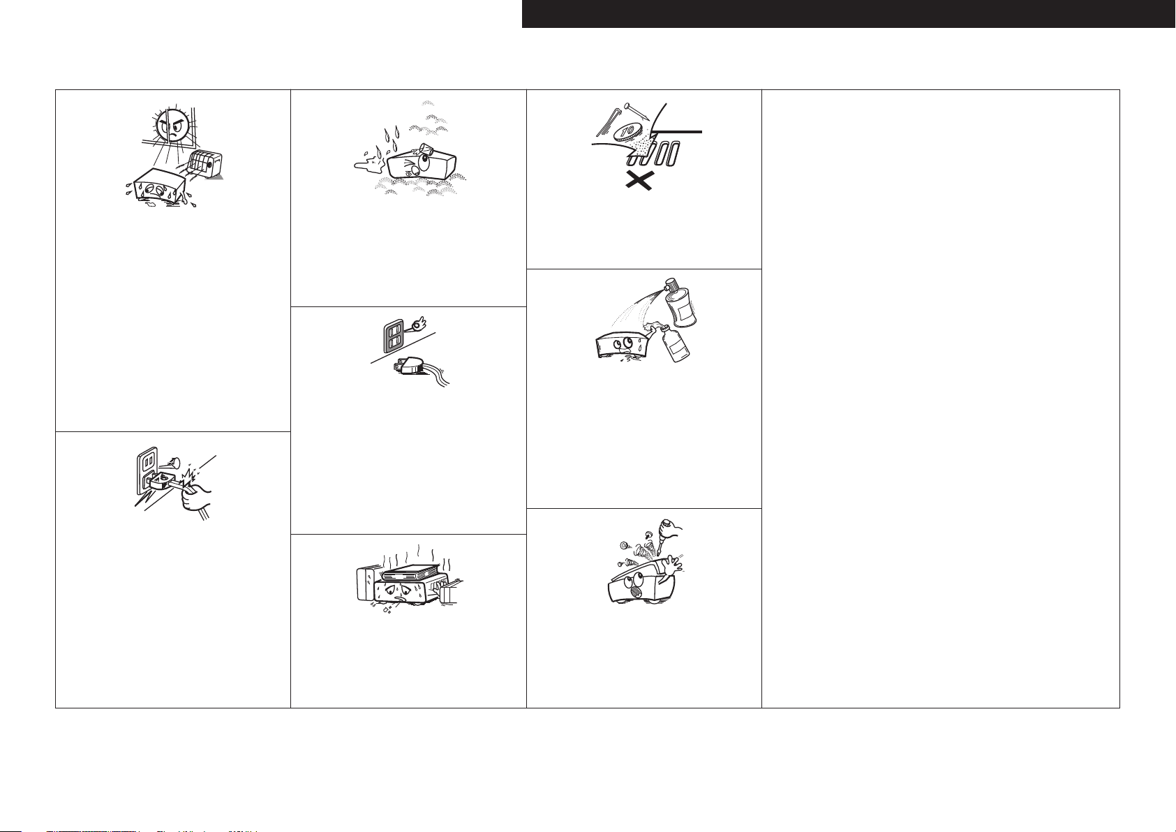
CAUTION:
• The ventilation should not be impeded by covering the ventilation openings with items,
such as newspapers, tablecloths, curtains, etc.
• No naked flame sources, such as lighted candles, should be placed on the unit.
• Observe and follow local regulations regarding battery disposal.
• Do not expose the unit to dripping or splashing fluids.
• Do not place objects filled with liquids, such as vases, on the unit.
ACHTUNG:
• Die Belüftung sollte auf keinen Fall durch das Abdecken der Belüftungsöffnungen durch
Gegenstände wie beispielsweise Zeitungen, Tischtücher, Vorhänge o. Ä. behindert
werden.
• Auf dem Gerät sollten keinerlei direkte Feuerquellen wie beispielsweise angezündete
Kerzen aufgestellt werden.
• Bitte beachten Sie bei der Entsorgung der Batterien die örtlich geltenden
Umweltbestimmungen.
• Das Gerät sollte keiner tropfenden oder spritzenden Flüssigkeit ausgesetzt werden.
• Auf dem Gerät sollten keine mit Flüssigkeit gefüllten Behälter wie beispielsweise Vasen
aufgestellt werden.
ATTENTION:
• La ventilation ne doit pas être gênée en recouvrant les ouvertures de la ventilation avec des
objets tels que journaux, rideaux, tissus, etc.
• Aucune flamme nue, par exemple une bougie, ne doit être placée sur l’appareil.
• Veillez à respecter les lois en vigueur lorsque vous jetez les piles usagées.
• L’appareil ne doit pas être exposé à l’eau ou à l’humidité.
• Ne pas poser d’objet contenant du liquide, par exemple un vase, sur l’appareil.
ATTENZIONE:
• Le aperture di ventilazione non devono essere ostruite coprendole con oggetti, quali
giornali, tovaglie, tende e così via.
• Non posizionate sull’unità fiamme libere, come ad esempio candele accese.
• Prestate attenzione agli aspetti legati alla tutela dell’ambiente nello smaltimento delle
batterie.
• L’apparecchiatura non deve essere esposta a gocciolii o spruzzi.
• Non posizionate sull’unità alcun oggetto contenente liquidi, come ad esempio i vasi.
PRECAUCIÓN:
• La ventilación no debe quedar obstruida por haberse cubierto las aperturas con objetos
como periódicos, manteles, cortinas, etc.
• No debe colocarse sobre el aparato ninguna fuente inflamable sin protección, como velas
encendidas.
• A la hora de deshacerse de las pilas, respete la normativa para el cuidado del medio
ambiente.
• No exponer el aparato al goteo o salpicaduras cuando se utilice.
• No colocar sobre el aparato objetos llenos de líquido, como jarros.
WAARSCHUWING:
• De ventilatie mag niet worden belemmerd door de ventilatieopeningen af te dekken met
bijvoorbeeld kranten, een tafelkleed, gordijnen, enz.
• Plaats geen open vlammen, bijvoorbeeld een brandende kaars, op het apparaat.
• Houd u steeds aan de milieuvoorschriften wanneer u gebruikte batterijen wegdoet.
• Stel het apparaat niet bloot aan druppels of spatten.
• Plaats geen voorwerpen gevuld met water, bijvoorbeeld een vaas, op het apparaat.
OBSERVERA:
• Ventilationen bör inte förhindras genom att täcka för ventilationsöppningarna med föremål
såsom tidningar, bordsdukar, gardiner osv.
• Inga blottade brandkällor, såsom tända ljus, får placeras på apparaten.
• Tänk på miljöaspekterna när du bortskaffar batterier.
• Apparaten får inte utsättas för vätska.
• Placera inte föremål fyllda med vätska, t.ex. vaser, på apparaten.
• Avoid high temperatures.
Allow for sufficient heat dispersion when installed in a rack.
• Vermeiden Sie hohe Temperaturen.
Beachten Sie, dass eine ausreichende Belüftung gewährleistet
wird, wenn das Gerät auf ein Regal gestellt wird.
• Eviter des températures élevées.
Tenir compte d’une dispersion de chaleur suffisante lors de
l’installation sur une étagère.
• Evitate di esporre l’unità a temperature elevate.
Assicuratevi che vi sia un’adeguata dispersione del calore
quando installate l’unità in un mobile per componenti audio.
• Evite altas temperaturas.
Permite la suficiente dispersión del calor cuando está
instalado en la consola.
• Vermijd hoge temperaturen.
Zorg er bij installatie in een audiorack voor, dat de door
het toestel geproduceerde warmte goed kan worden
afgevoerd.
• Undvik höga temperaturer.
Se till att det finns möjlighet till god värmeavledning vid
montering i ett rack.
• Handle the power cord carefully.
Hold the plug when unplugging the cord.
• Gehen Sie vorsichtig mit dem Netzkabel um.
Halten Sie das Kabel am Stecker, wenn Sie den Stecker
herausziehen.
• Manipuler le cordon d’alimentation avec précaution.
Tenir la prise lors du débranchement du cordon.
• Manneggiate il cavo di alimentazione con attenzione.
Tenete ferma la spina quando scollegate il cavo dalla presa.
• Maneje el cordón de energía con cuidado.
Sostenga el enchufe cuando desconecte el cordón de
energía.
• Hanteer het netsnoer voorzichtig.
Houd het snoer bij de stekker vast wanneer deze moet
worden aan- of losgekoppeld.
• Hantera nätkabeln varsamt.
Håll i kabeln när den kopplas från el-uttaget.
• Keep the unit free from moisture, water, and dust.
• Halten Sie das Gerät von Feuchtigkeit, Wasser und Staub
fern.
• Protéger l’appareil contre l’humidité, l’eau et la poussière.
• Tenete l’unità lontana dall’umidità, dall’acqua e dalla
polvere.
• Mantenga el equipo libre de humedad, agua y polvo.
• Laat geen vochtigheid, water of stof in het apparaat
binnendringen.
• Utsätt inte apparaten för fukt, vatten och damm.
• Unplug the power cord when not using the unit for long
periods of time.
• Wenn das Gerät längere Zeit nicht verwendet werden soll,
trennen Sie das Netzkabel vom Netzstecker.
• Débrancher le cordon d’alimentation lorsque l’appareil n’est
pas utilisé pendant de longues périodes.
• Scollegate il cavo di alimentazione quando prevedete di non
utilizzare l’unità per un lungo periodo di tempo.
• Desconecte el cordón de energía cuando no utilice el equipo
por mucho tiempo.
Neem altijd het netsnoer uit het stopkontakt wanneer het
•
apparaat gedurende een lange periode niet wordt gebruikt.
• Koppla loss nätkabeln om apparaten inte kommer att
användas i lång tid.
* (For apparatuses with ventilation holes)
• Do not obstruct the ventilation holes.
• Decken Sie den Lüftungsbereich nicht ab.
• Ne pas obstruer les trous d’aération.
• Non coprite i fori di ventilazione.
• No obstruya los orificios de ventilación.
• De ventilatieopeningen mogen niet worden beblokkeerd.
• Täpp inte till ventilationsöppningarna.
• Do not let foreign objects into the unit.
Lassen Sie keine fremden Gegenstände in das Gerät kommen.
•
• Ne pas laisser des objets étrangers dans l’appareil.
• Non inserite corpi estranei all’interno dell’unità.
• No deje objetos extraños dentro del equipo.
• Laat geen vreemde voorwerpen in dit apparaat vallen.
• Se till att främmande föremål inte tränger in i apparaten.
• Do not let insecticides, benzene, and thinner come in
contact with the unit.
• Lassen Sie das Gerät nicht mit Insektiziden, Benzin oder
Verdünnungsmitteln in Berührung kommen.
• Ne pas mettre en contact des insecticides, du benzène et
un diluant avec l’appareil.
• Assicuratevi che l’unità non entri in contatto con insetticidi,
benzolo o solventi.
• No permita el contacto de insecticidas, gasolina y diluyentes
con el equipo.
• Voorkom dat insecticiden, benzeen of verfverdunner met dit
toestel in contact komen.
• Se till att inte insektsmedel på spraybruk, bensen och
thinner kommer i kontakt med apparatens hölje.
• Never disassemble or modify the unit in any way.
• Versuchen Sie niemals das Gerät auseinander zu nehmen
oder zu verändern.
• Ne jamais démonter ou modifier l’appareil d’une manière ou
d’une autre.
• Non smontate né modificate l’unità in alcun modo.
• Nunca desarme o modifique el equipo de ninguna manera.
• Dit toestel mag niet gedemonteerd of aangepast worden.
• Ta inte isär apparaten och försök inte bygga om den.
ENGLISHDEUTSCHFRANCAISITALIANOESPAÑOLNEDERLANDSSVENSKA
II
ENGLISH
ITALIANO ESPAÑOL NEDERLANDS SVENSKAENGLISH DEUTSCH FRANCAIS
• DECLARATION OF CONFORMITY
We declare under our sole responsibility that this product, to which this
declaration relates, is in conformity with the following standards:
EN60065, EN55013, EN55020, EN61000-3-2 and EN61000-3-3.
Following the provisions of 2006/95/EC and 2004/108/EC Directive.
• ÜBEREINSTIMMUNGSERKLÄRUNG
Wir erklären unter unserer Verantwortung, daß dieses Produkt, auf das
sich diese Erklärung bezieht, den folgenden Standards entspricht:
EN60065, EN55013, EN55020, EN61000-3-2 und EN61000-3-3.
Entspricht den Verordnungen der Direktive 2006/95/EC und 2004/108/EC.
• DECLARATION DE CONFORMITE
Nous déclarons sous notre seule responsabilité que l’appareil, auquel se
réfère cette déclaration, est conforme aux standards suivants:
EN60065, EN55013, EN55020, EN61000-3-2 et EN61000-3-3.
D’après les dispositions de la Directive 2006/95/EC et 2004/108/EC.
• DICHIARAZIONE DI CONFORMITÀ
Dichiariamo con piena responsabilità che questo prodotto, al quale la
nostra dichiarazione si riferisce, è conforme alle seguenti normative:
EN60065, EN55013, EN55020, EN61000-3-2 e EN61000-3-3.
In conformità con le condizioni delle direttive 2006/95/EC e 2004/108/EC.
QUESTO PRODOTTO E’ CONFORME
AL D.M. 28/08/95 N. 548
• DECLARACIÓN DE CONFORMIDAD
Declaramos bajo nuestra exclusiva responsabilidad que este producto al
que hace referencia esta declaración, está conforme con los siguientes
estándares:
EN60065, EN55013, EN55020, EN61000-3-2 y EN61000-3-3.
Siguiendo las provisiones de las Directivas 2006/95/EC y 2004/108/EC.
• EENVORMIGHEIDSVERKLARING
Wij verklaren uitsluitend op onze verantwoordelijkheid dat dit produkt,
waarop deze verklaring betrekking heeft, in overeenstemming is met de
volgende normen:
EN60065, EN55013, EN55020, EN61000-3-2 en EN61000-3-3.
Volgens de bepalingen van de Richtlijnen 2006/95/EC en 2004/108/EC.
• ÖVERENSSTÄMMELSESINTYG
Härmed intygas helt på eget ansvar att denna produkt, vilken detta intyg
avser, uppfyller följande standarder:
EN60065, EN55013, EN55020, EN61000-3-2 och EN61000-3-3.
Enligt stadgarna i direktiv 2006/95/EC och 2004/108/EC.
DENON EUROPE
Division of D&M Germany GmbH
An der Landwehr 19, Nettetal,
D-41334 Germany
A NOTE ABOUT RECYCLING:
This product’s packaging materials are recyclable and can be reused. Please dispose of any materials
in accordance with the local recycling regulations.
When discarding the unit, comply with local rules or regulations.
Batteries should never be thrown away or incinerated but disposed of in accordance with the local
regulations concerning battery disposal.
This product and the supplied accessories, excluding the batteries, constitute the applicable product
according to the WEEE directive.
HINWEIS ZUM RECYCLING:
Das Verpackungsmaterial dieses Produktes ist zum Recyceln geeignet und kann wieder verwendet
werden. Bitte entsorgen Sie alle Materialien entsprechend der örtlichen Recycling-Vorschriften.
Beachten Sie bei der Entsorgung des Gerätes die örtlichen Vorschriften und Bestimmungen.
Die Batterien dürfen nicht in den Hausmüll geworfen oder verbrannt werden; bitte entsorgen Sie die
Batterien gemäß der örtlichen Vorschriften.
Dieses Produkt und das im Lieferumfang enthaltene Zubehör (mit Ausnahme der Batterien!)
entsprechen der WEEE-Direktive.
UNE REMARQUE CONCERNANT LE RECYCLAGE:
Les matériaux d’emballage de ce produit sont recyclables et peuvent être réutilisés. Veuillez disposer
des matériaux conformément aux lois sur le recyclage en vigueur.
Lorsque vous mettez cet appareil au rebut, respectez les lois ou réglementations en vigueur.
Les piles ne doivent jamais être jetées ou incinérées, mais mises au rebut conformément aux lois en vigueur sur la
mise au rebut des piles.
Ce produit et les accessoires inclus, à l’exception des piles, sont des produits conformes à la directive DEEE.
NOTA RELATIVA AL RICICLAGGIO:
I materiali di imballaggio di questo prodotto sono riutilizzabili e riciclabili. Smaltire i materiali conformemente alle
normative locali sul riciclaggio.
Per lo smaltimento dell’unità, osservare le normative o le leggi locali in vigore.
Non gettare le batterie, né incenerirle, ma smaltirle conformemente alla normativa locale sui rifiuti chimici.
Questo prodotto e gli accessori inclusi nell’imballaggio sono applicabili alla direttiva RAEE, ad eccezione delle batterie.
ACERCA DEL RECICLAJE:
Los materiales de embalaje de este producto son reciclables y se pueden volver a utilizar. Disponga de estos materiales
siguiendo los reglamentos de reciclaje de su localidad.
Cuando se deshaga de la unidad, cumpla con las reglas o reglamentos locales.
Las pilas nunca deberán tirarse ni incinerarse. Deberá disponer de ellas siguiendo los reglamentos de su localidad
relacionados con los desperdicios químicos.
Este producto junto con los accesorios empaquetados es el producto aplicable a la directiva RAEE excepto pilas.
EEN AANTEKENING MET BETREKKING TOT DE RECYCLING:
Het inpakmateriaal van dit product is recycleerbaar en kan opnieuw gebruikt worden. Er wordt verzocht om zich van
elk afvalmateriaal te ontdoen volgens de plaatselijke voorschriften.
Volg voor het wegdoen van de speler de voorschriften voor de verwijdering van wit- en bruingoed op.
Batterijen mogen nooit worden weggegooid of verbrand, maar moeten volgens de plaatselijke voorschriften
betreffende chemisch afval worden verwijderd.
Op dit product en de meegeleverde accessoires, m.u.v. de batterijen is de richtlijn voor afgedankte elektrische en
elektronische apparaten (WEEE) van toepassing.
OBSERVERA ANGÅENDE ÅTERVINNING:
Produktens emballage är återvinningsbart och kan återanvändas. Kassera det enligt lokala återvinningsbestämmelser.
När du kasserar enheten ska du göra det i överensstämmelse med lokala regler och bestämmelser.
Batterier får absolut inte kastas i soporna eller brännas. Kassera dem enligt lokala bestämmelser för kemiskt avfall.
Denna apparat och de tillbehör som levereras med den uppfyller gällande WEEE-direktiv, med undantag av
batterierna.
III

ENGLISH
Contentsn
Getting Started·······································································2
Flow of Operations Through Playback ········································ 2
Cautions on Handling ···································································2
Cautions on Installation ·······························································2
Preparations ··················································································3
Accessories ··················································································3
Insert Batteries in the Remote Control Unit ································· 3
Operating Range of the Remote Control Unit ······························3
Part Names and Functions ··························································· 4
Front Panel····················································································4
Display ·························································································· 5
Rear Panel·····················································································6
Remote Control Unit ····································································· 7
Connections ·············································································9
Important Information ··································································9
Cables Used for Connections ······················································· 9
Converting Input Video Signals for Output
(Video Conversion Function) ·······················································10
Installing / Setting the Speakers ···············································11
Speaker Connections ··································································13
Connecting Devices ····································································14
Connecting the Power Cord ·······················································23
Once Connections are Completed ·············································23
Turning the Power On ································································23
Turning the Power Off ································································23
Settings ····················································································24
GUI Menu Map ············································································24
GUI Menu Operation ··································································· 25
Example of the Display of the GUI Mark at a Title ······················25
Examples of GUI Menu Screen Displays ···································· 25
Selecting the Input Source ·························································26
Make the Optimal Speaker Settings, and Correct the Room
Acoustics (Audyssey™ Auto Setup)··········································27
Making Detailed Settings (Manual Setup)································32
Making the Input Settings (Input Setup) ··································43
Playback ···················································································50
Important Information ································································50
Playing Components ··································································· 50
Playing a Blu-ray Disc Player/DVD Player ····································50
iPod® Playback ···········································································50
Tuning in Radio Stations ····························································52
Listening to FM/AM Broadcasts ·················································52
RDS (Radio Data System) ···························································53
RDS Search·················································································53
PTY Search ·················································································53
TP Search····················································································54
RT (Radio Text) ···········································································54
Playing Network Audio, USB Memory Devices ·······················54
Listening to Internet Radio ·························································56
Playing Files Stored on a Computer ············································58
Playing Files Stored on USB Memory Devices ··························· 59
Listening to Napster ···································································60
Operations During Playback ······················································62
Adjusting the Master Volume ·····················································62
Turning Off the Sound Temporarily (Muting) ······························62
Listening with Headphones ························································62
Switching the front speakers ······················································ 62
To Stop ·······················································································62
Stopping Playback Temporarily ··················································· 62
Fast-forwarding or Fast-reversing ···············································62
To Cue to the Beginning of a Track ············································62
Playing Repeatedly ·····································································63
Selecting Tracks··········································································63
Shuffling Playback·······································································63
Playing in Random Order ····························································63
Searching Pages ········································································· 63
Searching by First Letter ·····························································63
Selecting the Surround Mode ···················································· 64
Adjusting the Sound and Picture Quality
(Audio/Video Adjust) ··································································67
Adjusting the Sound (Audio Adjust) ············································67
Adjusting the Picture Quality (Picture Adjust) ····························· 72
Checking the Status (Information) ·····························73
Other Operations and Convenient Functions ········74
Other Operations ········································································74
Recording on an External Device (REC OUT mode) ··················· 74
Convenient Functions ·································································75
HDMI Control Function ······························································· 75
Setting the Power to Standby After a Certain Amount of Time
(Sleep Timer Function) ································································ 76
Adjust the Volume of the Speakers ············································76
Saving Frequently Used Settings (Quick Select Function) ··········77
Playing the Same Network Audio on Different Devices
Connected in a Network (Party Mode Function) ·························77
Operating a Wireless LAN-Compatible Mobile Terminal to Play
Music and Still Pictures ······························································78
Operating the AVR-3310 with a Browser
(Web Control Function) ······························································· 79
Various Memory Functions ························································· 80
Playing in ZONE2/ZONE3
(Multi-zone Function) ························································81
Audio Output ···············································································81
q Zone Playback by Speaker Output ·········································81
w Zone Playback by Audio Output (PRE OUT) ···························81
Video Output ··············································································· 81
Video Connection········································································81
Playback ······················································································· 82
Quick Select Function ·································································83
ENGLISH
Getting Started
Operating the Connected Devices by Remote
Control Unit············································································83
Getting Started
Operating the Main Remote Control Unit ································83
Registering Preset Codes ···························································83
Connections Settings Playback Remote ControlMulti-zone Information Troubleshooting Specifications
Operating Components ······························································84
Assigning buttons that are Not Used to Operate Other Devices
(Punch Through Function) ··························································· 87
Operating the Sub Remote Control Unit ·································· 88
Switching Zones ········································································· 89
Switching the Multi-zone Input Source to the Same Input
Source as Used in the MAIN ZONE ············································89
Setting the Zone for Which the Sub Remote Control Unit is
Used (ZONE SELECT LOCK Mode) ············································89
Setting the Remote ID ································································ 89
Resetting the Settings ································································89
Other Information ·······························································90
Troubleshooting···································································97
Restoring All the Settings to as They were at the Time of
Purchase (Resetting the Microprocessor) ······························· 100
Specifications ······································································100
List of preset codes ··································End of this manual
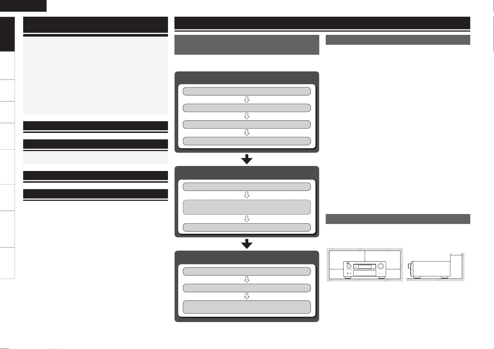
Flow of Operations Through
Playback
Perform the operations leading to playback on the AVR-3310 in the
order shown below.
Connections
Installing/Setting the Speakers
Speaker Connections (vpage 13)
Connecting Devices (vpage 14)
Turning the Power On (vpage 23)
(vpage 11)
Settings
Audyssey™ Auto Setup (vpage 27)
Manual Setup (vpage 32)
Perform “Manual Setup” as necessary.b
Cautions on Handling
• Before turning the power switch on
Check once again that all connections are correct and that there are
no problems with the connection cables.
• Power is supplied to some of the circuitry even when the unit is
set to the standby mode. When traveling or leaving home for long
periods of time, be sure to unplug the power cord from the power
outlet.
• About condensation
If there is a major difference in temperature between the inside of
the unit and the surroundings, condensation (dew) may form on
the operating parts inside the unit, causing the unit not to operate
properly.
If this happens, let the unit sit for an hour or two with the power
turned off and wait until there is little difference in temperature
before using the unit.
• Cautions on using mobile phones
Using a mobile phone near this unit may result in noise. If so, move
the mobile phone away from this unit when it is in use.
• Moving the unit
Turn off the power and unplug the power cord from the power
outlet.
Next, disconnect the connection cables to other system units before
moving the unit.
• Note that the illustrations in these instructions may differ from the
actual unit for explanation purposes.
Cautions on Installation
Input Setup (vpage 43)
Playback
Playing Components (vpage 50)
Selecting the Surround Mode (vpage 64)
Adjusting the Sound and Picture Quality
(vpage 67)
Note:
For proper heat dispersal, do not install this unit in a confined
space, such as a bookcase or similar enclosure.
b
b Note
b b
Wall
Preparations
r t u
Q1
o
Q0
Thank you for purchasing this DENON product. To ensure proper
operation, please read this owner’s manual carefully before using the
product.
After reading them, be sure to keep them for future reference.
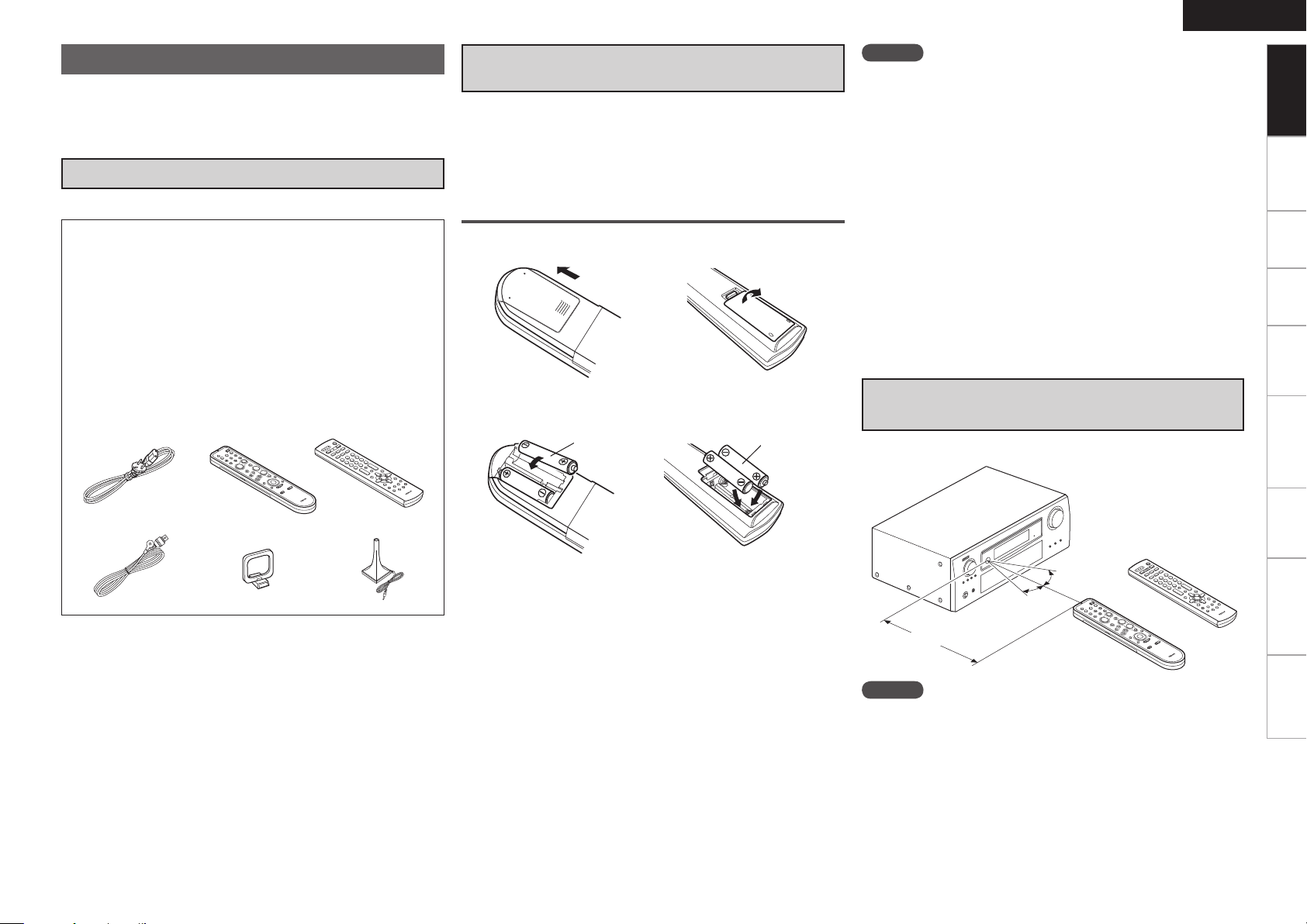
Accessories
Check that the following parts are supplied with the product.
q Owner’s manual ...................................................................... 1
w Getting started ........................................................................1
e Service station list ...................................................................1
r Power cord (Cord length: Approx. 1.7 m) ................................ 1
t Main remote control unit (RC-1118) ........................................ 1
y R6/AA batteries (for RC-1118) ................................................. 2
u Sub remote control unit (RC-1121) .......................................... 1
i R03/AAA batteries (for RC-1121) ............................................. 2
o FM indoor antenna ..................................................................1
Q0 AM loop antenna ..................................................................... 1
Q1 Setup microphone
(DM-A409, Cord length: Approx. 7.6 m) .................................. 1
Insert Batteries in the Remote Control
Unit
In addition to the AVR-3310, the included main remote control unit
(RC-1118) can also be used to operate the equipment listed below.
q DENON system components
w Non-DENON system components
To operate component products other than DENON, you must set
the preset code (vpage 83 “Registering Preset Codes”).
Inserting the Batteries
q Lift the clasp and remove the rear lid.
(RC-1118) (RC-1121)
w Load the two batteries properly as indicated by the marks in the
battery compartment.
(RC-1118) (RC-1121)
R6/AA
R03/AAA
ENGLISH
NOTE
Insert the specified batteries in the remote control unit.
•
Replace the batteries with new ones if the set does not operate
•
even when the remote control unit is operated close to the unit. (The
supplied batteries are only for verifying operation.)
When inserting the batteries, be sure to do so in the proper direction,
•
following the “q” and “w” marks in the battery compartment.
To prevent damage or leakage of battery fluid:
•
Do not use a new battery together with an old one.
•
Do not use two different types of batteries.
•
Do not attempt to charge dry batteries.
•
Do not short-circuit, disassemble, heat or dispose of batteries in
•
flames.
If the battery fluid should leak, carefully wipe the fluid off the inside
•
of the battery compartment and insert new batteries.
Remove the batteries from the remote control unit if it will not be in
•
use for long periods.
Used batteries should be disposed of in accordance with the local
•
regulations regarding battery disposal.
Operating Range of the Remote Control
Unit
Point the remote control unit at the remote sensor when operating it.
Getting Started
Connections Settings Playback Remote ControlMulti-zone Information Troubleshooting Specifications
e Put the rear cover back on.
30°
(RC-1121)
30°
or
Approx. 7 m
(RC-1118)
NOTE
The set may function improperly or the remote control unit may not
operate if the remote control sensor is exposed to direct sunlight,
strong artificial light from an inverter type fluorescent lamp or infrared
light.
ENGLISH
t
q
w
e
r
Q5 Q6Q4Q3
y
o
Q0
Q1
Q2
ui
W5
Q7
Q8
Q9
W0
W1 W4W3W2
E1
E6
W9E0
E4E5
E2
E3
W8
W7 W6
Getting Started
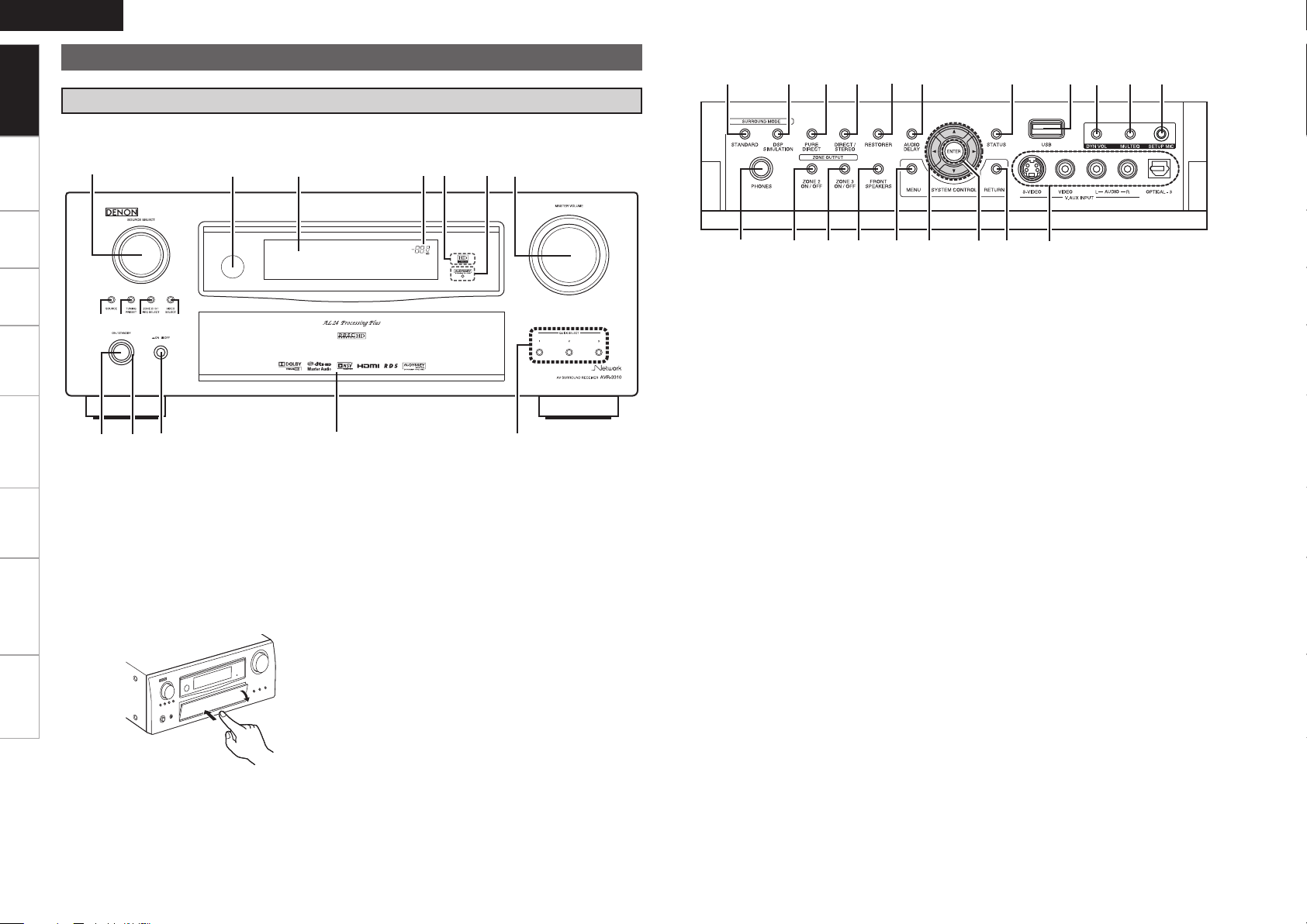
Part Names and Functions
Front Panel
For buttons not explained here, see the page indicated in parentheses ( ).
Connections Settings Playback Remote ControlMulti-zone Information Troubleshooting Specifications
GWith the door openH
q Power operation button ···························· (23)
w Power indicator ·········································· (23)
e Power switch ··············································(23)
r Door
When you are using buttons and/or terminals
behind the door, press the bottom of the door to
open it. When not using buttons and/or terminals
behind the door, close it. Be careful not to catch
your fingers when closing the door.
t QUICK SELECT buttons ····························· (77)
y MASTER VOLUME control knob ··············· (62)
u AUDYSSEY
DYNAMIC VOLUME™ indicator ················ (69)
i HD AUDIO indicator ···································· (65)
o Master volume indicator
Q0 Display
Q1 Remote control sensor ································ (3)
Q2 SOURCE SELECT knob ······························ (26)
Q3 SOURCE button ·········································· (26)
Q4 TUNING PRESET button ···························· (52)
Q5 ZONE 2/3 / REC SELECT button ··········(74, 82)
Q6 VIDEO SELECT button ······························· (46)
Q7 Headphones jack ········································ (62)
Q8 ZONE2 ON/OFF button ······························ (82)
Q9 ZONE3 ON/OFF button ······························ (82)
W0 FRONT SPEAKERS button ························· (62)
W1 MENU button ·············································· (24)
W2 Cursor buttons (uio p) ·························· (25)
W3 ENTER button ·············································(25)
W4 RETURN button ··········································(25)
W5 V.AUX INPUT connectors ·························· (20)
W6 SETUP MIC jack ·········································· (28)
W7 MULTEQ
®
button ······································· (69)
W8 DYNAMIC VOLUME™ button (DYN VOL) ··· (70)
W9 USB port ······················································ (20)
E0 STATUS button ·········································· (73)
E1 AUDIO DELAY button ································ (71)
E2 RESTORER button ······································ (71)
E3 DIRECT/STEREO button ···························· (65)
E4 PURE DIRECT button ································· (66)
E5 DSP SIMULATION button ·························· (65)
E6 STANDARD button ····································· (64)
ioQ5
Q8
W0 Q0Q1
Q6
Q2Q4
Q3
Q7Q9 u
wq e r t y
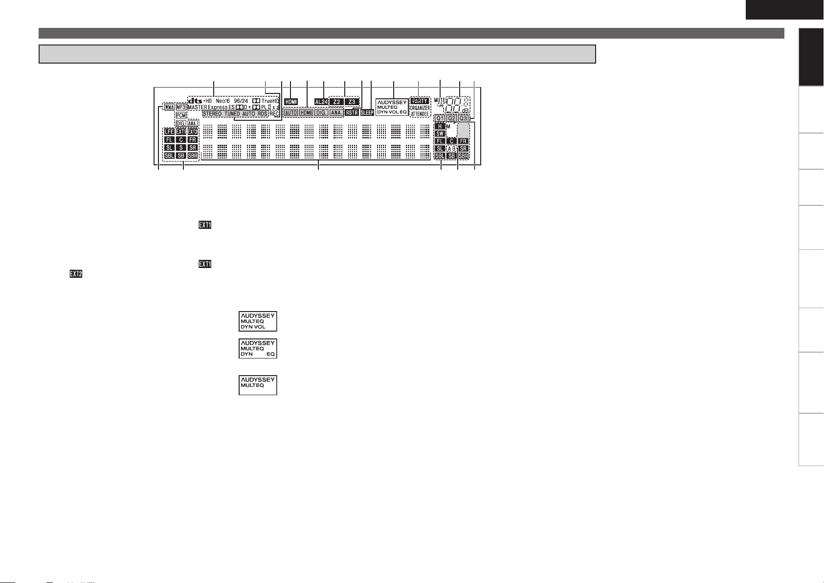
Display
ENGLISH
Part Names and Functions
Getting Started
Connections Settings Playback Remote ControlMulti-zone Information Troubleshooting Specifications
q Input signal indicators
w Input signal channel indicators
These light when digital signals are input.
When playing HD Audio sources, the“ ”
indicator lights when an extension channel (a
channel other than the front, center, surround,
surround back or LFE channel) is input. If there
are two or more extension channels, the “ ”
and “ ” indicators light.
e Information display
The input source name, surround mode, setting
values and other information are displayed
here.
r Output signal channel indicators
t Front speaker indicators
These light according to the settings of the front
A and B speakers.
y Monitor output indicators
This indicator lights up when an HDMI monitor
is connected.
u QUICK SELECT indicators
i Master volume indicator
o MUTE indicator
This lights when the mute mode is selected.
Q0 PARTY indicators
These indicators light during party mode.
• ORGANIZER
This lights to indicate that party mode has
started as Organizer.
• ATTENDEE
This lights to indicate that party mode has
started as Attendee.
Q1 AUDYSSEY MULTEQ indicators
Lighting is as follows, depending on the setting
of “Dynamic EQ” (vpage 69) and “Dynamic
Volume” (vpage 70).
•
•
•
: When “Dynamic EQ” and “Dynamic
Volume” are “ON”.
: When the “Dynamic EQ” setting is
“ON” and the “Dynamic Volume”
setting is “OFF”.
: When “Dynamic EQ” and “Dynamic
Volume” are “OFF”.
Q2 SLEEP indicator
This lights when the sleep mode is selected.
Q3 RESTORER indicator
This lights when the RESTORER mode is
selected.
Q4 Multi zone indicators
These light when the power for the respective
zone is turned on.
Q5 AL24 indicator
This lights when AL24 Processing Plus (vpage
91) is activated.
Q6 Input mode indicators
Q7 HDMI indicator
This lights when playing using HDMI
connections.
Q8 Tuner reception mode indicators
These light according to the reception conditions
when the input source is set to “TUNER”.
• STEREO
In the FM mode, these light when receiving
analog stereo broadcasts.
• TUNED
Lights when the broadcast is properly tuned in.
• AUTO
These light when in the auto tuning mode.
• RDS
These light when receiving RDS broadcasts.
Q9 Recording output source indicator
This lights when the REC OUT mode is
selected.
W0 Decoder indicators
These light when the respective decoders are
operating.
ENGLISH
t
e
y
Q0
u
i
o
Q1
Q5
Q5
o
r
wq
Q2
Q3Q4
Q6Q7Q6
Getting Started
Part Names and Functions
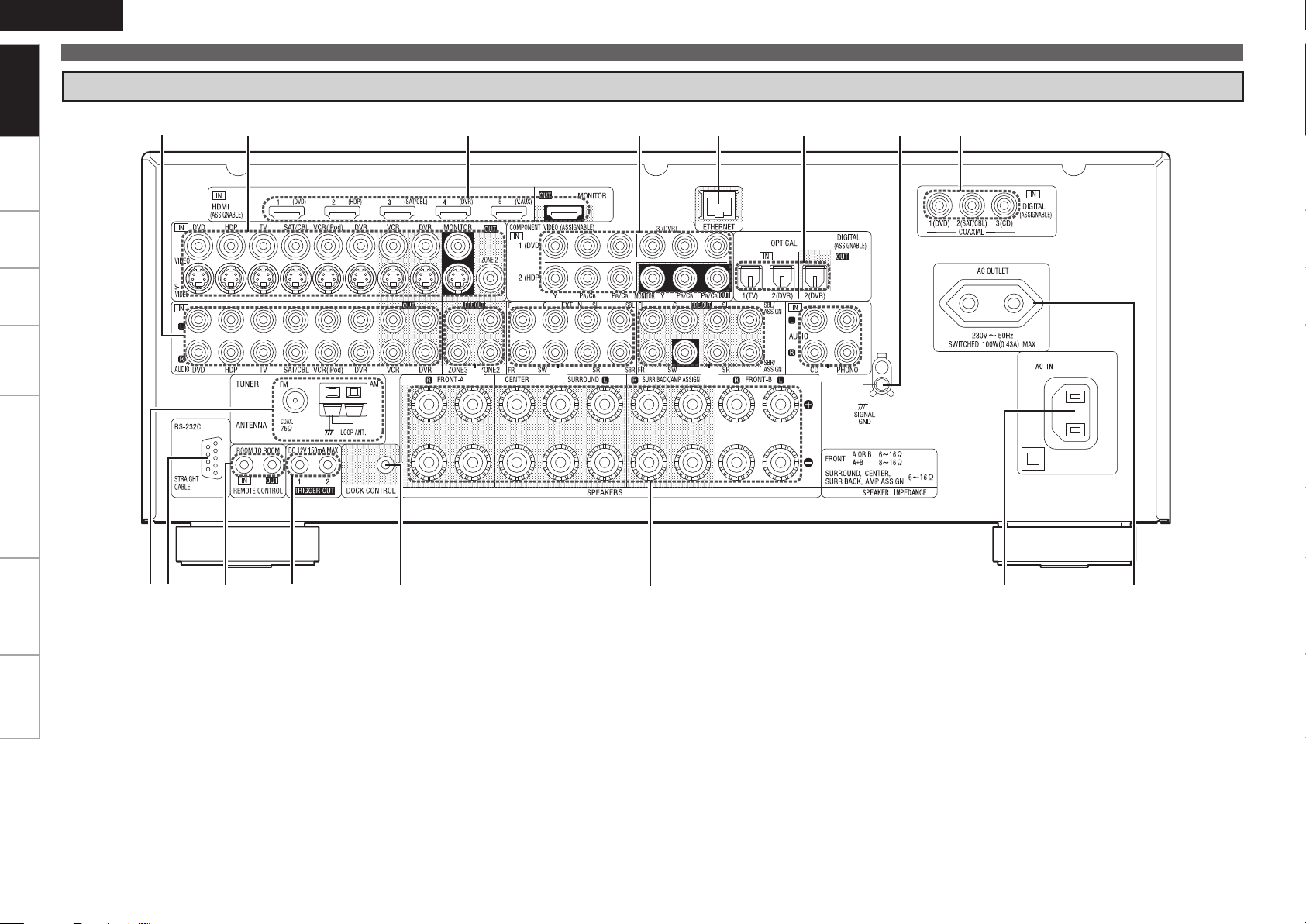
Rear Panel
Connections Settings Playback Remote ControlMulti-zone Information Troubleshooting Specifications
q FM/AM antenna terminals ························ (19)
w RS-232C connector ····································· (21)
e REMOTE CONTROL jacks ·························· (21)
r TRIGGER OUT jacks ··································· (21)
t DOCK CONTROL jack ································· (16)
y Speaker terminals ······································ (13)
u AC inlet ························································ (23)
i AC OUTLET ················································· (23)
o Digital audio connectors ···················· (16 ~ 19)
Q0 SIGNAL GND terminal ······························· (17)
Q1 ETHERNET connector ································ (22)
Q2 COMPONENT VIDEO connectors ···(15, 16, 18)
Q3 HDMI connectors ········································ (14)
Q4 VIDEO / S-VIDEO connectors ············ (15 ~ 19)
Q5 Analog audio connectors ··················· (16 ~ 19)
Q6 PRE OUT connectors ···························· (21, 81)
Q7 EXT. IN connectors ····································· (20)
w
q
e
t
r
y
u
i
o
Q0
Q2
Q1
Q3
Q4
Q5
Q6
Q7
W0
Q9
r
Q8
W1
W3
E0
W9
W6
W5
W4
W7
W8
W2
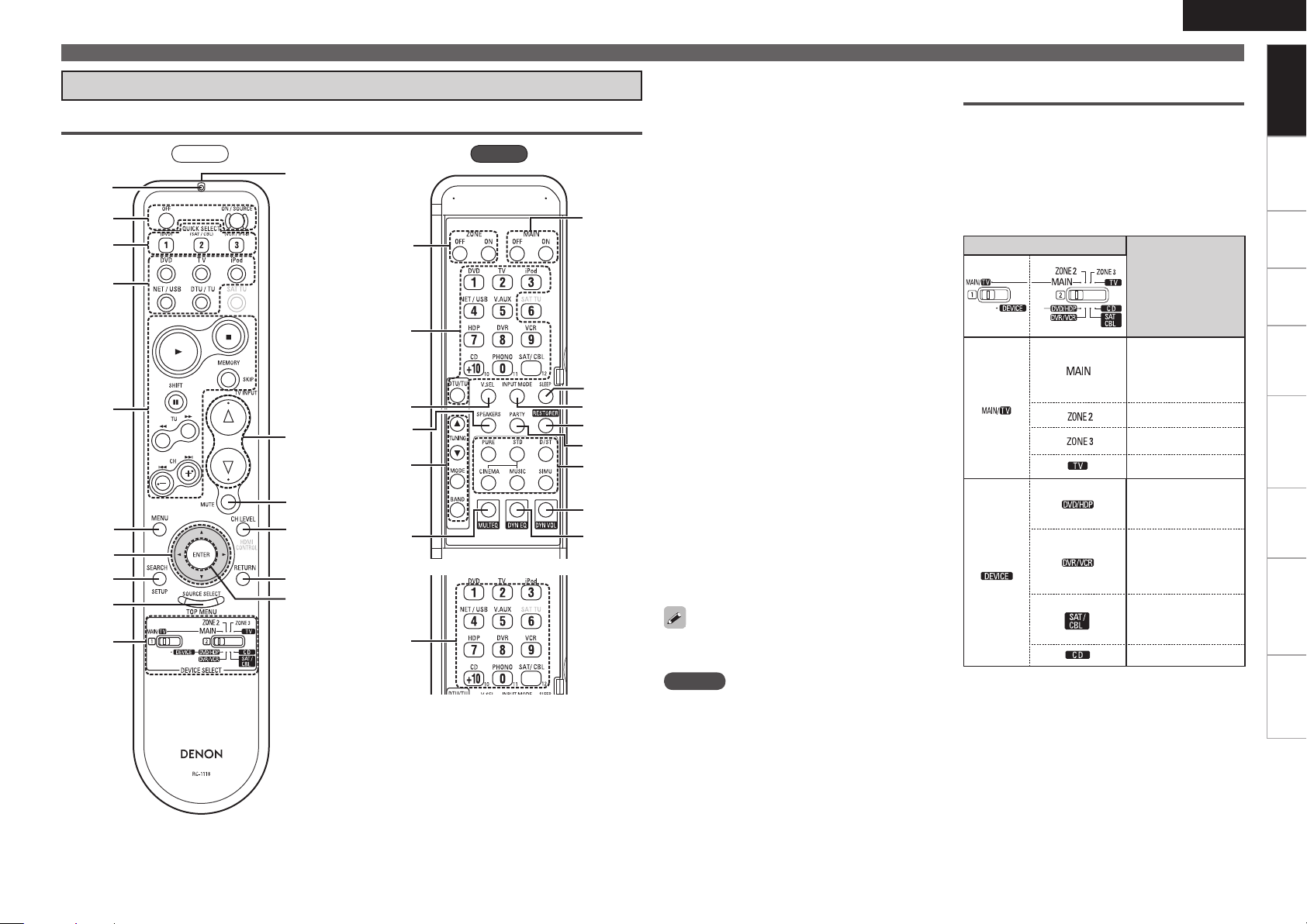
Remote Control Unit
Main Remote Control Unit (RC-1118)
Front
Rear
q Indicator ······················································(83)
w Power buttons ············································ (23)
e QUICK SELECT buttons ·····························(77)
r Input source select button ························ (26)
t System buttons ····························(62, 84 ~ 86)
y MENU button ··············································(24)
u Cursor buttons (uio p) ························· (25)
i SEARCH button ··········································(63)
o SOURCE SELECT button ··························· (26)
Q0 DEVICE SELECT switches ·······················(7, 83)
Q1 Remote control signal transmitter ············· (3)
Q2 Master volume control buttons ················ (62)
Q3 Muting button (MUTE) ······························ (62)
Q4 Channel level adjustment button ······· (34, 76)
Q5 RETURN button ·········································· (25)
Q6 ENTER button ············································· (25)
Q7 ZONE power button ··································· (82)
Q8 VIDEO SELECT button ·······························(46)
Q9 Front height speaker on/off button ·········· (68)
W0 Tuner operation buttons ··························· (52)
W1 MULTEQ
®
button ······································· (69)
W2 Number buttons (0 ~ 9, +10) ····················· (83)
W3 MAIN ZONE power buttons ······················(23)
W4 SLEEP TIMER button ·································· (76)
W5 INPUT MODE button ·································· (47)
W6 RESTORER button ······································ (71)
W7 PARTY button ············································· (77)
W8 Surround mode buttons ····················(64 ~ 66)
W9 DYNAMIC VOLUME™ button···················· (70)
E0 DYNAMIC EQ™ button ······························(69)
For buttons not explained here, see the page
indicated in parentheses ( ).
NOTE
Buttons on the back panel may operate when the
•
back lid is pressed.
The SAT TU and HDMI CONTROL buttons cannot
•
be used.
ENGLISH
Part Names and Functions
Operations possible by remote
control
Operations on the AVR-3310
n
Operations on five devices other that
n
the AVR-3310
• Preset the remote control codes of the devices
to be operated (vpage 83).
• Switch two device selector switches according
to the devices to be operated.
Position of switches
Operable devices
AVR-3310
(MAIN ZONE)
iPod, TUNER,
NET/USB
AVR-3310 (ZONE2)
AVR-3310 (ZONE3)
TV
Blu-ray disc player
or
DVD Player
Dgital video
recorder
or
Video deck
Satellite receiver
or
Cable TV
CD player
Multi-zone (ZONE2 / ZONE3)
n
operations (vpage 82)
Punch through setting (vpage 87)
n
Getting Started
Connections Settings Playback Remote ControlMulti-zone Information Troubleshooting Specifications
ENGLISH
q
t
r
y
i
o
Q0
u
e
w
Q6
Q5
Q8
W0
W1
W2
W3
Q9
Q7
Q2
Q3
Q4
Q1
Getting Started Connections Settings Playback Remote ControlMulti-zone Information Troubleshooting Specifications
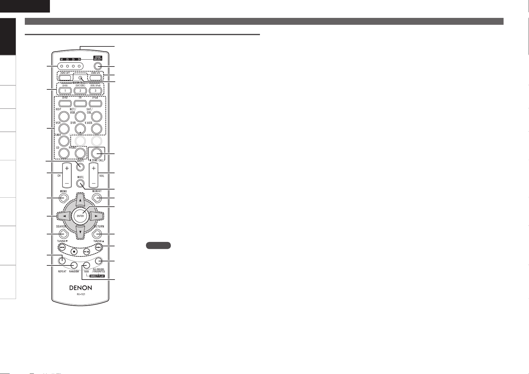
Getting Started
Part Names and Functions
Sub Remote Control Unit (RC-1121)
q ZONE indicators ········································· (89)
w QUICK SELECT buttons ························(77, 83)
e Input source select buttons ················· (26, 88)
r SHIFT button ··········································(57, 88)
t Channel button (CH) ···························· (52, 88)
y MENU button ········································ (24, 88)
u Cursor buttons (uio p) ···················· (25, 88)
i SEARCH button ···································· (63, 88)
o REPEAT button ·····································(63, 88)
Q0 RANDOM button ·································· (63, 88)
Q1 Remote control signal transmitter ············· (3)
Q2 ZONE SELECT button ································ (89)
Q3 Zone power on/off buttons ······················· (82)
Q4 Advanced setup button ····························· (89)
Q5 MAIN ZONE call button ······················· (82, 89)
Q6 Master volume control buttons
(VOL) ······················································ (62, 82)
Q7 Muting button (MUTE) ························ (62, 82)
Q8 MEMORY button ·································· (52, 88)
Q9 ENTER button ·······································(25, 88)
W0 RETURN button ····································(25, 88)
W1 System buttons ····································(62, 88)
W2 ALL MUSIC/FAVORITES
(DIRECT PLAY) button ······························· (88)
W3 USB (DIRECT PLAY) button ················· (59, 88)
NOTE
The SAT TU and DTU buttons cannot be used.
Connections
R
L
R
L
ENGLISH
Getting Started Settings Playback Remote ControlMulti-zone Information Troubleshooting Specifications
Important Information
Connections for all compatible audio and video signal formats
are described in this owner’s manual. Please select the types of
connections suited for the equipment you are connecting.
After connections are completed, certain settings must be made on
the receiver. Make the settings indicated “
for the individual items.
NOTE
• Do not plug in the power cord until all connections have been completed.
• When making connections, also refer to the operating instructions
of the other components.
• Be sure to connect the left and right channels properly (left with
left, right with right).
• Do not bundle power cords together with connection cables. Doing
so can result in humming or noise.
Set as Necessary
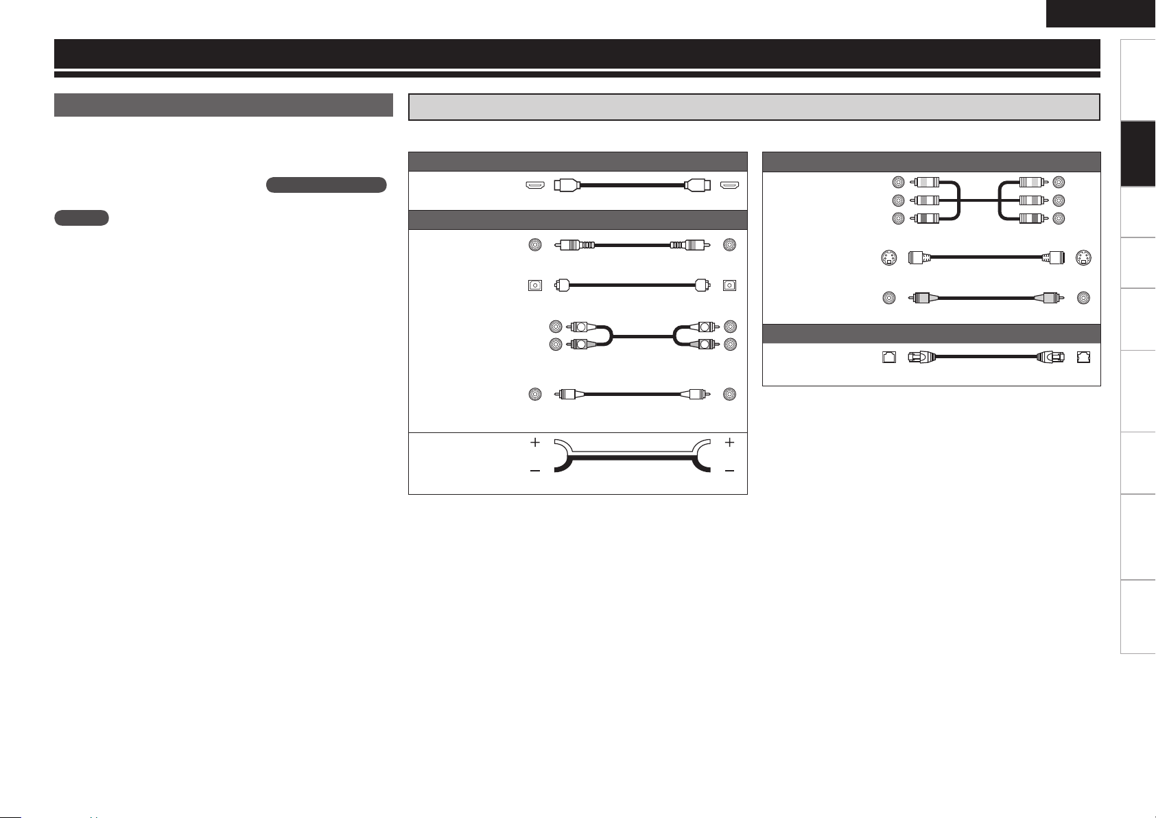
Cables Used for Connections
Select the cables (sold separately) according to the equipment being connected.
Audio and video cables
HDMI connections
”
HDMI cable
Audio cables
Coaxial digital
connections
Optical digital
connections
Analog
connections
(stereo, surround)
Analog
connections
(monaural, for
subwoofer)
Speaker
connections
(White)
(Red)
Coaxial digital cable
Optical cable
Audio cable
Audio cable
Speaker cables
Component
video
connections
S-Video
connections
Video
connections
Network
connections
Connections
Video cables
(Green)
(Blue)
(Red)
Component video cable
S-Video cable
(Yellow)
Video cable
Other cables
Ethernet cable
ENGLISH
Getting Started Connections Settings Playback Remote ControlMulti-zone Information Troubleshooting Specifications
Important Information
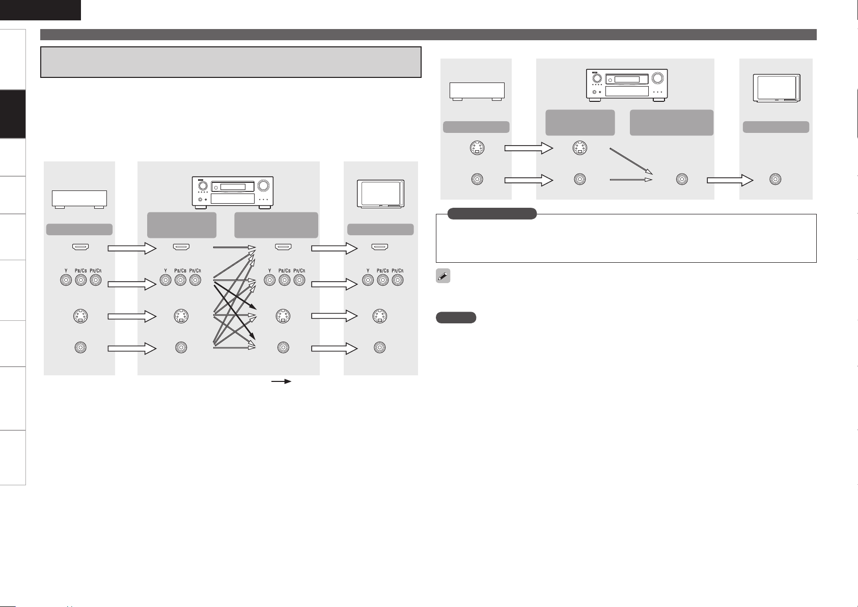
Converting Input Video Signals for Output
(Video Conversion Function)
The AVR-3310 has 4 different types of video input/output terminal (HDMI, Component video, S-Video,
Connections
Video).
Use the terminals according to the devices to be connected.
This function automatically converts various formats of video signals input to the AVR-3310 into the format
used to output the video signals from the AVR-3310 to a monitor (vpage 96 “Relationship Between
Video Signals and Monitor Output”).
GFlow of video signals for MAIN ZONEH
AVR-3310
Video device
Monitor
Video device
Output
S-Video connector
Video connector
GFlow of video signals for ZONE2H
AVR-3310
Input
(IN)
S-Video connector
Video connector Video connector Video connector
Output
(MONITOR OUT)
Monitor
Input
Output
HDMI connector
Component video
connectors
S-Video connector
Video connector
Input
(IN)
HDMI connector
Component video
connectors
S-Video connector
Video connector
Output
(MONITOR OUT)
HDMI connector
Component video
connectors
S-Video connector S-Video connector
Video connector
: When 480i/576i signals are input
Input
HDMI connector
Component video
connectors
Video connector
Set as Necessary
Set when using the video conversion function.
•
“Video Convert” (vpage 46)
Set when changing the resolution of the video signal.
•
“Resolution” (vpage 47)
Resolutions of HDMI-compatible TVs can be checked at “HDMI Information” – “Monitor Information”
(vpage 73).
NOTE
HDMI signals cannot be converted into analog signals.
•
When a non-standard video signal from a game machine or some other source is input, the video
•
conversion function might not operate.
480p/576p/1080i/720p/1080p component video input signals cannot be converted into S-Video or Video
•
format.
0
z1
z
3
z
2
Installing / Setting the Speakers
z
2
z
1
z3
z
1
z
2
z1
z2
ENGLISH
Getting Started Settings Playback Remote ControlMulti-zone Information Troubleshooting Specifications
• The AVR-3310 is compatible with various types of
surround playback.
• Decide on the surround modes to be played on the
AVR-3310 before making connections and settings.
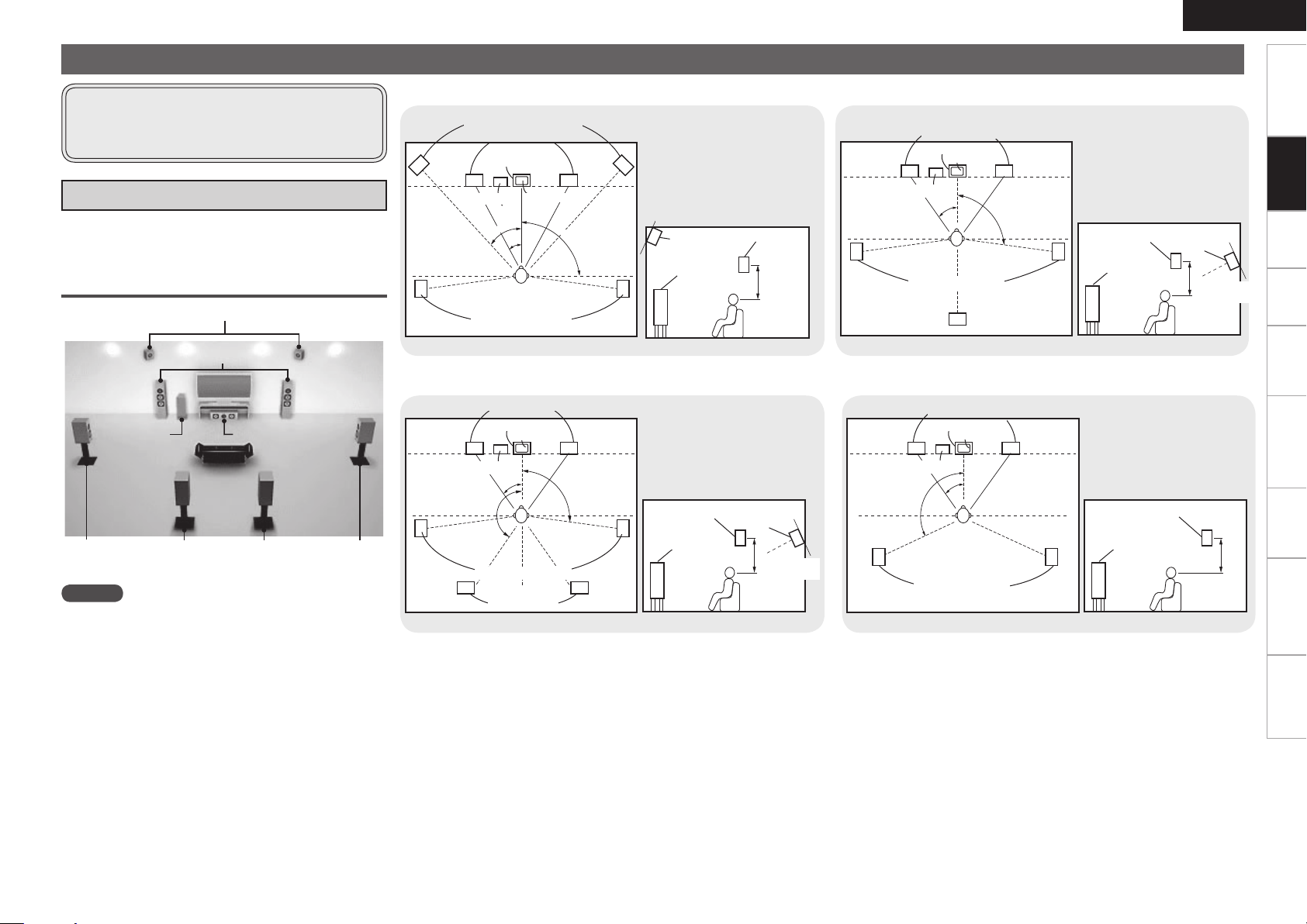
a Determine the Speaker Layout
Below we introduce examples of speaker layouts. Refer to
these to arrange your speakers according to their type and
how you want to use them.
Installing All the Speakers
Front Height speakers
Front speakers
Subwoofer
Surround
Surround back speakers
speaker
NOTE
It is not possible to use the surround back speakers and
front height speakers simultaneously.
Center speaker
Surround
speaker
When 7.1ch (Front Height Speaker) Connectedn
Front height speakers
Front speakers
Center speaker
z1: 22˚ ~ 30˚
z2: 22˚ ~ 45˚
z3: 90˚ ~ 110˚
Subwoofer
Surround speakers
As seen from above
G
Monitor
Point slightly
downwards
Front height
speaker
Front speaker
60 to 90 cm
H
As seen from the side
G
Surround
speaker
H
When 7.1ch (Surround Back Speaker) Connectedn
Front speakers
Center speaker
Monitor
z1: 22 ~ 30˚
z2: 90˚ ~ 110˚
When 6.1ch (Surround Back Speaker) Connectedn
Front speakers
Center speaker
Monitor
Subwoofer
Surround speakers
Surround back
As seen from above
G
speaker
H G
z1: 22 ~ 30˚
z2: 90˚ ~ 110˚
Surround
speaker
Front
speaker
60 to 90 cm
As seen from the side
Surround back
speaker
Point slightly
downwards
H
Connections
When 5.1ch Connectedn
Front speakers
Center speaker
Monitor
z1: 22 ~ 30˚
z2: 120˚
z3: 135˚ ~ 150˚
Subwoofer
Surround speakers
Surround back
speakers
As seen from above
G
Surround
speaker
Front
speaker
H
As seen from the side
G
Surround back
speaker
60 to 90 cm
Point slightly
downwards
H
Subwoofer
Surround speakers
As seen from above
G
Front
speaker
H G
Surround
speaker
60 to 90 cm
As seen from the side
H
ENGLISH
Getting Started Settings Playback Remote ControlMulti-zone Information Troubleshooting Specifications
Installing/Setting the Speakers
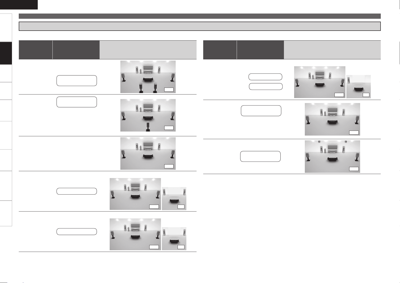
s Set the “Amp Assign” Mode According to the Speaker Layout
The signals output from the AVR-3310’s SURR. BACK/AMP ASSIGN speaker terminals can be switched (vpage 33 “Amp Assign”).
Connections
Amp assign
mode
(vpage 33)
SURR. BACK /
AMP ASSIGN
Speaker connections
Example of speaker installation
(Number of channels played)
Amp assign
(vpage 33)
mode
SURR. BACK /
AMP ASSIGN
Speaker connections
Example of speaker installation
(Number of channels played)
MAIN ZONE ZONE2 or ZONE3
Normal
(Default)
Normal
Normal
ZONE2
Surround Back
Speakers
Surround Back L
Speaker
Connect to the “L”
b
speaker terminal.
Set “Surround Back”
b
(vpage 33) to
“1spkr”.
Not connected
Set “Surround Back”
b
(vpage 33) to
“None”.
ZONE2 speakers
(7.1)
(6.1)
(5.1)
MAIN ZONE ZONE2
(5.1) (2)
ZONE2/3-MONO
Front A Bi-Amp
or
Front B Bi-Amp
Front Height
ZONE2 speaker
L ch :
ZONE3 speaker
R ch :
Front A or B
speakers
For connections,
b
see “About Bi-amp
Connections” (vpage
13).
Front height
Speakers
(5.1) (1)
(5.1)
(7.1)
ZONE3
ZONE3 speakers
MAIN ZONE ZONE3
(5.1) (2)
w q
w q
w q w q
*/
w q
(R)
(L) (R)
w q w q
(L) (R) (L)
wq wq
(R) (L)
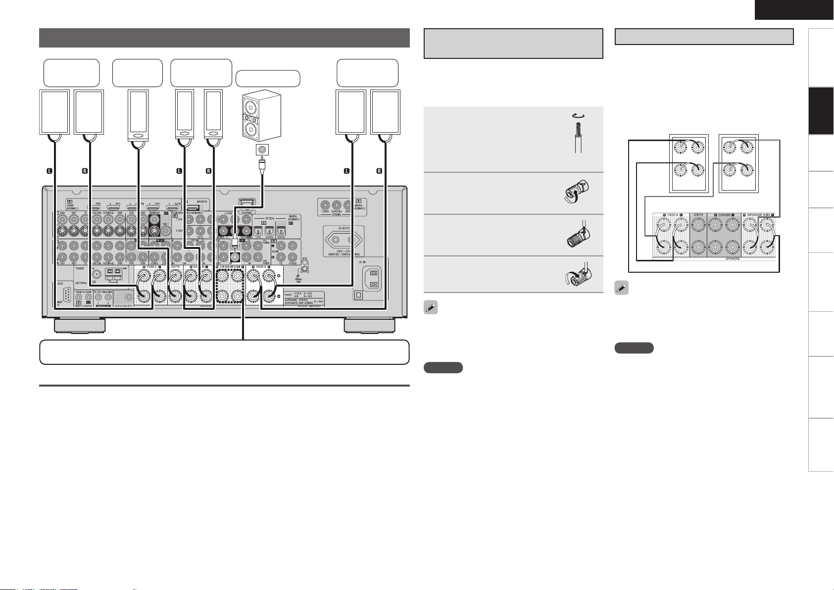
Speaker Connections
Front
speakers A
Center
speaker
Surround
speakers
Subwoofer
Subwoofer
with built-in
amplifier
Front
speakers B
Connecting the Speaker
Cables
Carefully check the left (L) and right (R) channels
and + (red) and – (black) polarities on the speakers
being connected to the AVR-3310, and be sure to
interconnect the channels and polarities correctly.
Peel off about 10 mm of
1
sheathing from the tip of
the speaker cable, then
either twist the core wire
tightly or terminate it.
Turn the speaker terminal
2
counterclockwise to
loosen it.
Insert the speaker cable’s
3
core wire to the hilt into
the speaker terminal.
Turn the speaker terminal
4
clockwise to tighten it.
ENGLISH
About Bi-amp Connections
These connections make for higher quality playback
sound with no interference between the signals of
the bass and treble units.
When the “Amp Assign” setting (vpage 33) is
“Front A Bi-Amp” or “Front B Bi-Amp”, connect
as follows. (The illustration shows a connection
example for the Front A Bi-Amp speakers.)
Front speakers A
AVR-3310
Getting Started Settings Playback Remote ControlMulti-zone Information Troubleshooting Specifications
Connections
For connections of the SURR. BACK/AMP ASSIGN speaker terminals, see “Set the “Amp Assign”
Mode According to the Speaker Layout” (vpage 12).
Protection Circuit
If the core wires touch the rear panel and the
screws etc., or the ± sides touch each other, the
protection circuit will be activated and the power
indicator will flash red at intervals of 0.5 secs.
If the protection circuit is activated, the speaker
output is isolated, and the power supply goes to
the standby state. If the power supply is turned off,
after the power supply cord is withdrawn, please
confirm that speaker cable and input cable are
connected.
Also, if replaying large sound levels by using
a speaker having an impedance less than that
specified (eg, 4 Ω/ohms), the temperature will rise,
and the protection circuit might be activated. The
power supply will go into the standby state, and the
power indicator will flash red at 2 second intervals.
In this case, please switch off the power supply,
and wait until the AVR-3310 has cooled down, and
the surrounding ventilation is good.
Even if there are no problems with the surrounding
ventilation and connections, in the event of the
protection circuit becoming activated, due to
thinking that the AVR-3310 has failed, please
contact DENON Service center after switching off.
Use speakers with an impedance of 6 to 16 Ω/ohms.
When using front A and B speakers simultaneously,
use speakers with an impedance of 8 to 16 Ω/
ohms.
NOTE
Connect so that the speaker cable core wires
•
do not protrude from the speaker terminal. The
protection circuit may be activated if the core
wires touch the rear panel or if the + and – sides
touch each other (v“Protection Circuit”).
Never touch the speaker terminals while the
•
power supply is connected. Doing so could result
in electric shock.
When in the “Front A Bi-Amp” and “Front B BiAmp” modes, the same signals are output from
the front speaker terminals and the AMP ASSIGN
terminals.
NOTE
Use speakers compatible with bi-amp
•
connections.
When making bi-amp connections, be sure to
•
remove the short-circuiting plate or wire between
the speaker’s woofer and tweeter terminals.
ENGLISH
065
)%.*
065
)%.*
065
)%.*
065
)%.*
065
)%.*
*/
)%.*
Getting Started Settings Playback Remote ControlMulti-zone Information Troubleshooting Specifications
Connecting Devices
Connections
n
n
n
n
n
n
n
Connecting Devices
Connecting Devices Equipped with HDMI
Terminals (vpage 14)
Connecting the Monitor (vpage 15)
Connecting the Playback Components
Blu-ray Disc Player / DVD Player (vpage 16)
•
Control dock for iPod (vpage 16)
•
CD Player (vpage 17)
•
Record Player (vpage 17)
•
Connecting the Recording Components
Video Cassette Recorder (vpage 17)
•
Digital Video Recorder (vpage 18)
•
Connect the Tuner
TV (vpage 18)
•
Satellite Receiver / Cable Tuner (vpage 19)
•
FM/AM (vpage 19)
•
Connections to Other Devices
Video Camera / Game Console (vpage 20)
•
USB Port (vpage 20)
•
Component with Multi-channel Output connectors
•
(vpage 20)
External Power Amplifier (vpage 21)
•
External Controller (vpage 21)
•
Connecting to a Home Network (LAN) (vpage 22)
Connecting Devices Equipped with
HDMI Terminals
Important Information
About HDMI
n
“HDMI” is the abbreviation of “High Definition Multimedia
Interface”. This interface allows transfer of digital video signals and
digital audio signals over a single HDMI cable.
“HDMI”, “HDMI logo” and “High-Definition Multimedia
Interface” are trademarks or registered trademarks of HDMI
Licensing LLC.
Functions Usable with HDMI Connections
n
Deep Color
Eliminates on-screen color banding, for smooth tonal transitions
and subtle gradations between colors. Enables increased contrast
ratio.
x.v.Color
Lets HDTVs display colors more accurately. Enables displays with
natural, vivid colors. “x.v.Color” is a Sony registered trademark.
Auto Lip Sync (vpage 35)
If you connect the receiver to a TV that supports the Auto Lip Sync
function, it can automatically correct delay between the audio and
video.
HDMI Control Function (vpage 75)
This function allows you to operate external devices from the
receiver and operate the receiver from external devices.
NOTE
These functions will not work if the device connected to the
•
HDMI terminal does not support Deep Color or x.v.Color signal
transfer or the Auto Lip Sync function.
The HDMI control function may not work depending on the
•
device it is connected to and its settings.
You cannot operate a TV or Blu-ray Disc player / DVD player that
•
is not compatible with the HDMI control function.
Copyright Protection System (HDCP)
n
The AVR-3310 supports HDCP (High-bandwidth Digital Contents
Protection). HDCP is a copyright protection technology for digital
video signals. The devices connected to the AVR-3310 must also
support HDCP.
NOTE
When a device that does not support HDCP is connected, video
signals are not properly output.
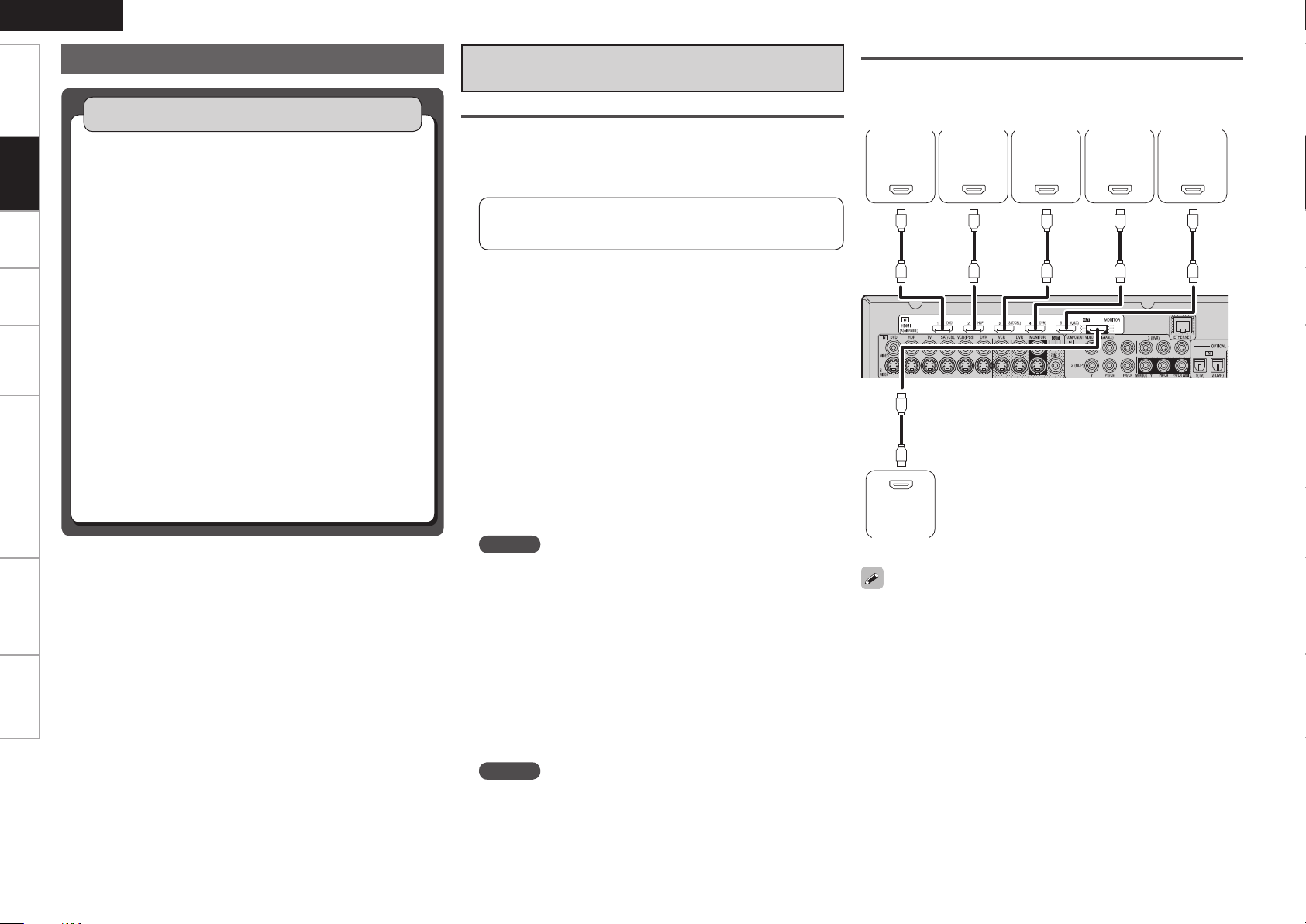
Connections
The AVR-3310 allows connection of inputs from up to 5 HDMI devices
and output to 1 monitor.
DVD
player
Monitor
Use a cable on which the HDMI logo is indicated (a certified HDMI
•
product) for connection to the HDMI connector. Normal playback
may not be possible when using a cable other than one on which the
HDMI logo is indicated (a non-HDMI-certified product).
When the AVR-3310 is connected to other devices with HDMI
•
cables, also connect the AVR-3310 and TV using an HDMI cable.
When a device supporting Deep Color signal transfer is connected,
•
use a cable compatible with HDMI version 1.3a.
Video signals are not output if the input video signals do not match
•
the monitor’s resolution. In this case, switch the Blu-ray Disc/
DVD player’s resolution to a resolution with which the monitor is
compatible.
HD player
Satellite
receiver
Digital
video
recorder
Game
console
ENGLISH
*/
7*%&0
$0.10/&/57*%&0
: 1# 13
7*%&0
*/
47*%&0
*/
Connecting Devices
Getting Started Settings Playback Remote ControlMulti-zone Information Troubleshooting Specifications
NOTE
If the GUI menu “Audio Out” setting (vpage 35) is set to “AMP”, the sound may be interrupted when
•
the monitor’s power is turned off.
The audio signal from the HDMI output terminal (sampling frequency, number of channels, etc.) may be
•
limited by the HDMI audio specifications of the connected device regarding permissible inputs.
Connecting to a Device Equipped with a DVI-D Terminal
n
When an HDMI/DVI conversion cable (sold separately) is used, the HDMI video signals are converted
to DVI signals, allowing connection to a device equipped with a DVI-D terminal.
NOTE
No sound is output when connected to a device equipped with a DVI-D terminal. Also make the audio
•
connections.
Signals cannot be output to DVI-D devices that do not support HDCP.
•
Depending on the combination of devices, the video signals may not be output.
•
Settings Related to HDMI Connections
Set as necessary. For details, see the respective reference pages.
Input Assign (vpage 44)
n
Set this to change the HDMI input terminal to which the input source is assigned.
HDMI Setup (vpage 35)
n
Make settings for HDMI video/audio output.
RGB Range
•
Auto Lip Sync
•
NOTE
The audio signals output from the HDMI connectors are only the HDMI input signals.
Audio Out
•
HDMI Control
•
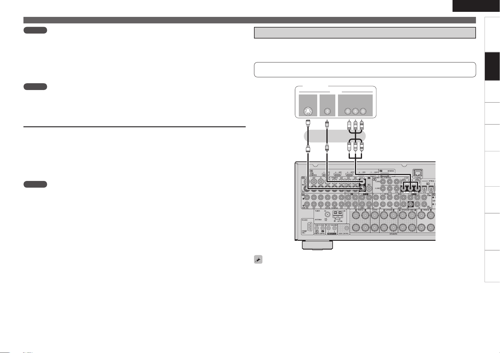
Connecting the Monitor
Select the terminal to use and connect the device.
•
For video connections, see “Converting Input Video Signals for Output (Video Conversion Function)”
•
(vpage 10).
For instructions on HDMI connections, see “Connecting Devices Equipped with HDMI Terminals” on
page 14.
Monitor
Connections
To listen to TV audio through this device, use the optical digital or analog connection.
ENGLISH
R
L
R
L
065
7*%&0
$0.10/&/57*%&0
: 1# 13
7*%&0
065
47*%&0
065
"6%*0
"6%*0
3-
065
065
$0"9*"-
R
L
R
L
"4%3
Getting Started Settings Playback Remote ControlMulti-zone Information Troubleshooting Specifications
Connecting Devices
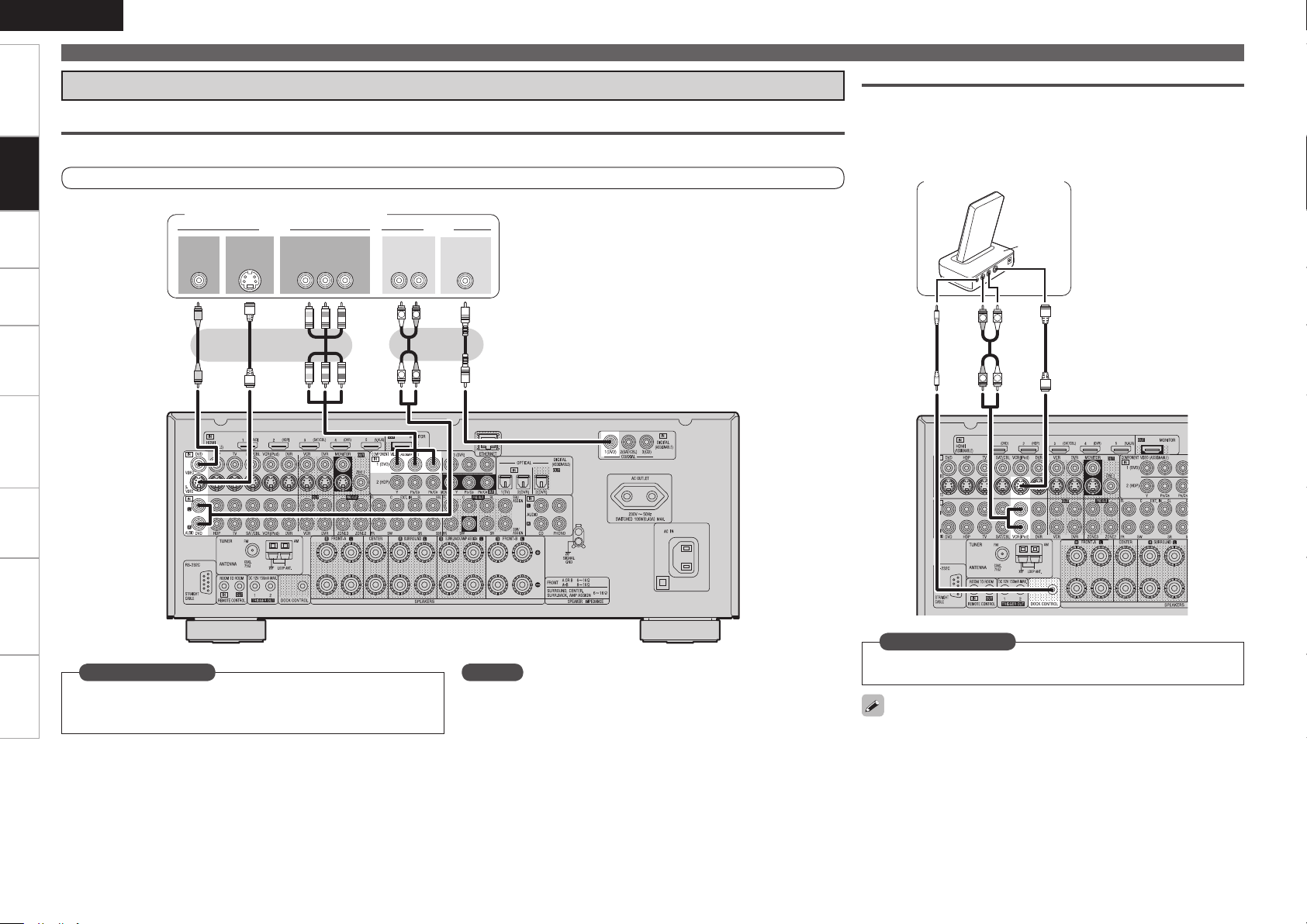
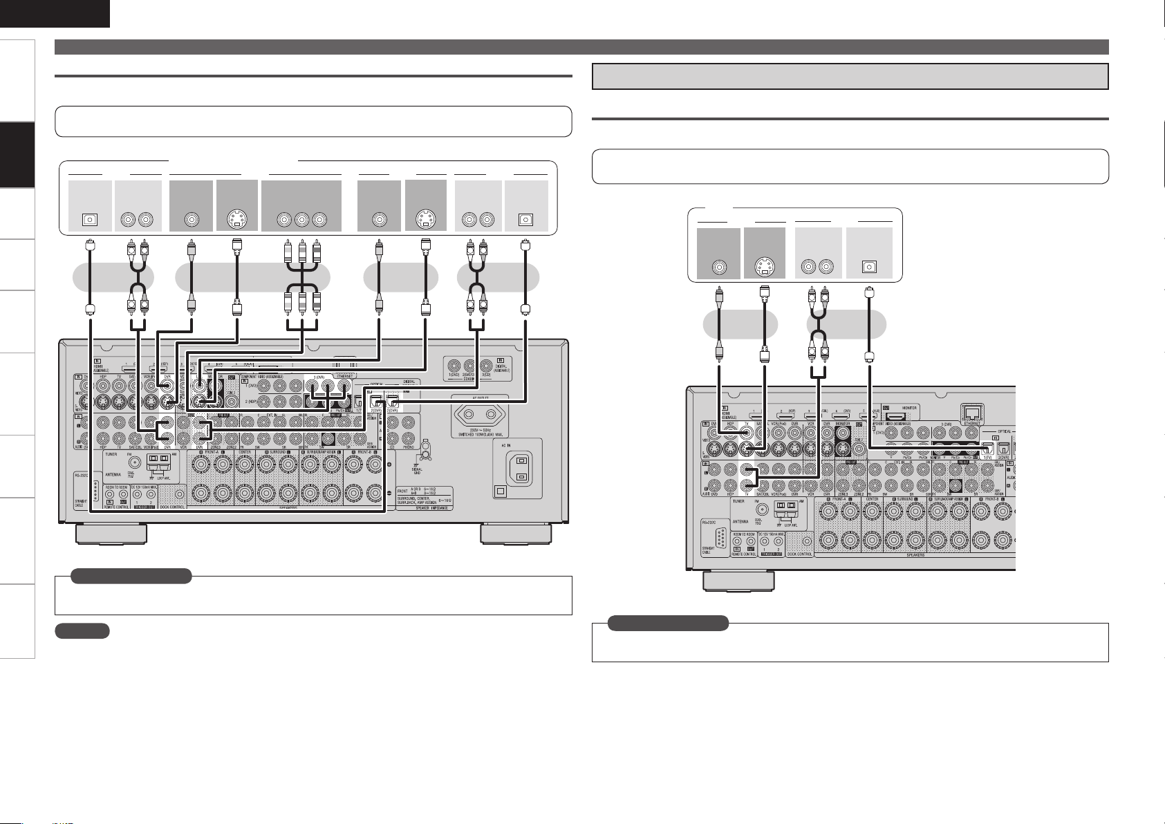
Connecting the Playback Components
Blu-ray Disc Player / DVD Player
Connections
Select the terminal to use and connect the device.
Control Dock for iPod
Use a DENON control dock for iPod (ASD-1R or ASD-11R, sold
separately) to connect the iPod to the AVR-3310. For instructions on
the control dock for iPod settings, refer to the control dock for iPod’s
operating instructions.
For instructions on HDMI connections, see “Connecting Devices Equipped with HDMI Terminals” on page 14.
Blu-ray Disc player / DVD player
Set this to change the input signal to which the input source is
Set as Necessary
assigned.
“Input Assign” (vpage 44)
NOTE
In the case of HD audio (Dolby TrueHD, DTS-HD and Dolby Digital Plus
and DTS Express) audio playback, connect with HDMI (vpage 14,
“Connecting Devices Equipped with HDMI Terminals”).
Control dock for iPod
Set as Necessary
Set other than when iPod is assigned to the VCR (iPod) terminal.
“Input Assign” – “iPod dock“ (vpage 46)
With the default settings, the iPod can be used connected to the VCR
(iPod) connector.
(/%
"6%*0
065
R
L
R
L
R
L
R
L
R
L
3-
065
"6%*0 7*%&0
"6%*0
3-
*/
"6%*0
"6%*0
065
7*%&0
47*%&0
065
7*%&0
*/
7*%&0
47*%&0
*/
R
L
R
L
"6%*0
"6%*0
3-
065
$0"9*"-
065
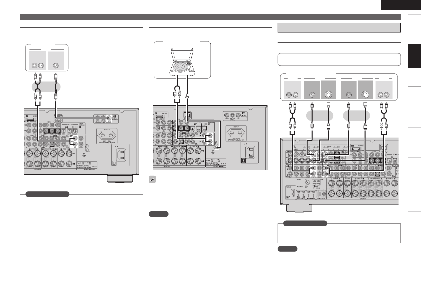
CD Player
Select the terminal to use and connect the device.
CD player
Record Player
Turntable
(MM cartridge)
Connecting Devices
Connecting the Recording Components
Video Cassette Recorder
Select the terminal to use and connect the device.
For instructions on HDMI connections, see “Connecting Devices
Equipped with HDMI Terminals” on page 14.
Video cassette recorder
ENGLISH
Getting Started Settings Playback Remote ControlMulti-zone Information Troubleshooting Specifications
Connections
Set as Necessary
Set this to change the input signal to which the input source is
assigned.
“Input Assign” (vpage 44)
The AVR-3310 is compatible with record players with an MM cartridge.
•
When you connect to a record player with an MC cartridge, use a
commercially available MC head amp or a step-up transformer.
When you increase the volume without connecting the record player,
•
there may be “booming” noise from the speakers.
NOTE
The SIGNAL GND terminal of the AVR-3310 is not a safety ground
connection. Connect it to reduce noise when noise is excessive.
Note that depending on the record player, connecting the ground line
may have the reverse effect of increasing noise. In this case, it is not
necessary to connect the ground line.
Set as Necessary
Set this to change the input signal to which the input source is
assigned.
“Input Assign” (vpage 44)
NOTE
To record video signals through the AVR-3310, use the same type
of video cable for connection between the AVR-3310 and the player
as the cable used for connection between the AVR-3310 and the
recorder.
ENGLISH
R
L
R
L
R
L
R
L
3- 3-
065
*/
"6%*0"6%*0 7*%&07*%&0
065 */
015*$"-015*$"-
*/
"6%*0"6%*0
065
7*%&0 7*%&0
$0.10/&/57*%&0
: 1# 13
065
47*%&0
065
47*%&0
*/
R
L
R
L
3-
065
"6%*0
7*%&0
"6%*0
065
7*%&0
47*%&0
065
065
015*$"-
Getting Started Connections Settings Playback Remote ControlMulti-zone Information Troubleshooting Specifications
Connections
Connecting Devices
Digital Video Recorder
Select the terminal to use and connect the device.
For instructions on HDMI connections, see “Connecting Devices Equipped with HDMI Terminals” on
page 14.
Connect the Tuner
TV
Select the terminal to use and connect the device.
Digital video recorder
For instructions on HDMI connections, see “Connecting Devices Equipped with HDMI Terminals” on
page 14.
TV
Set as Necessary
Set this to change the input signal to which the input source is assigned.
“Input Assign” (vpage 44)
NOTE
To record video signals through the AVR-3310, use the same type of video cable for connection between
•
the AVR-3310 and the player as the cable used for connection between the AVR-3310 and the recorder.
Do not connect the output of the component connected to the AVR-3310’s OPTICAL2 (DVR) output
•
connector to any input connector other than OPTICAL2 (DVR).
Set as Necessary
Set this to change the input signal to which the input source is assigned.
“Input Assign” (vpage 44)
Satellite Receiver / Cable Tuner (Set Top Box)
R
L
R
L
3-
065
"6%*0
7*%&0
"6%*0
065
7*%&0
47*%&0
065
065
$0"9*"-
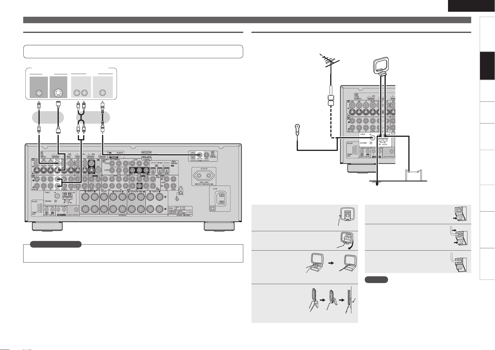
Select the terminal to use and connect the device.
FM/AM
An FM antenna cable plug can be connected directly.
ENGLISH
Connecting Devices
Getting Started Settings Playback Remote ControlMulti-zone Information Troubleshooting Specifications
For instructions on HDMI connections, see “Connecting Devices Equipped with HDMI Terminals” on
page 14.
Satellite Receiver / Cable Tuner
Set as Necessary
Set this to change the input signal to which the input source is assigned.
“Input Assign” (vpage 44)
Direction of broadcasting station
FM antenna
75 Ω/ohms
Coaxial cable
FM indoor antenna
(supplied)
n AM loop antenna assembly
Remove the vinyl tie and take
1
out the connection line.
Bend in the reverse direction.
2
With the antenna
-1
3
on top of any
stable surface.
With the antenna
-2
3
attached to a wall.
Mount
Installation hole Mount on wall, etc.
Connections
AM loop
antenna
(supplied)
Ground AM outdoor antenna
n Connection of AM antennas
Push the lever.
1
Insert the conductor.
2
Return the lever.
3
NOTE
• Do not connect two FM antennas simultaneously.
• Even if an external AM antenna is used, do not
disconnect the AM loop antenna.
• Make sure the AM loop antenna lead terminals do
not touch metal parts of the panel.
ENGLISH
R
L
R
L
47*%&0
065
"6%*07*%&0
7*%&0
065 065
015*$"-"6%*0
3-
065
R
L
R
L
R
L
R
L
R
L
R
L
46#
800'&3
$&/5&3 463306/%
#"$,
3-
463306/%
3-
'30/5
3-
"6%*0
Getting Started Connections Settings Playback Remote ControlMulti-zone Information Troubleshooting Specifications
Connecting Devices
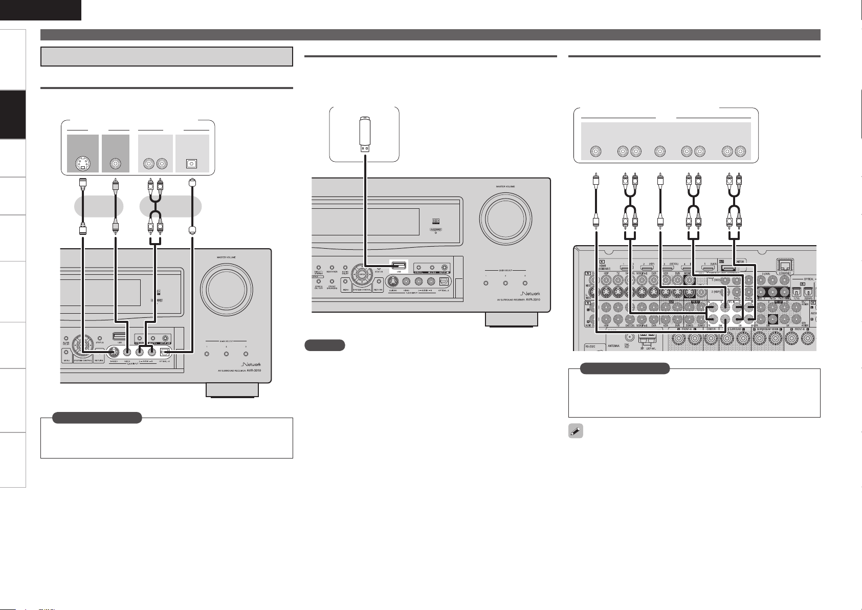
Connections to Other Devices
Video Camera / Game Console
Connections
Select the terminal to use and connect the device.
Video camera / Game console
USB Port
When you connect a USB memory device to the USB port, you can
enjoy music, etc., stored on the USB memory device.
USB memory
device
Component with Multi-channel Output connectors
The video signal can be connected in the same way as a Blu-ray Disc
player / DVD player (vpage 16 “Blu-ray Disc Player / DVD Player”).
Blu-ray Disc player / DVD player /
External decoder
Set as Necessary
Set this to change the input signal to which the input source is
assigned.
“Input Assign” (vpage 44)
0
NOTE
Do not use an extension cable when connecting a USB memory
device. This may cause radio interference with other devices.
Set as Necessary
To play analog signals input from the external input (EXT. IN)
terminal, set “Input Mode” (vpage 47) to “EXT. IN”.
“EXT. IN” can also be selected with [INPUT MODE] on the main
remote control unit.
When a device is connected to the SBL/SBR terminal of the external
input terminals (EXT. IN), set “Amp Assign” (vpage 33) to
“Normal”.
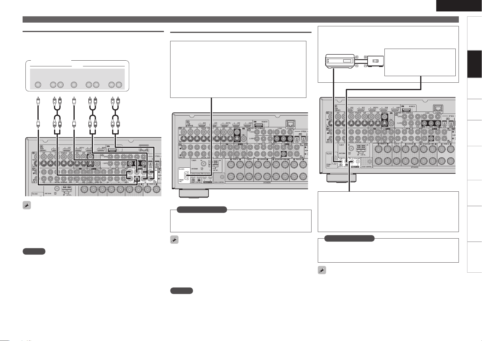
External Power Amplifier
R
L
R
L
R
L
R
L
R
L
R
L
46#
800'&3
$&/5&3 463306/%
#"$,
3-
463306/%
3-
'30/5
3-
"6%*0
"69
065
Select the terminal to use and connect the device.
•
Connect when using an external power amp or an amp you already
•
have.
Power amplifier
External Controller
RS-232C connector
n
When you connect an external control device, you can control
the AVR-3310 with the external control device. Perform the
operation below beforehand.
q Turn on the AVR-3310’s power.
w Turn off the AVR-3310’s power from the external
controller.
e Check that the AVR-3310 is in the standby mode.
REMOTE CONTROL jacksn
Infrared
retransmitter
Infrared
sensor
Input Output
ENGLISH
Connecting Devices
Extension jack for future use.
(Connect devices corresponding
with room to room function to
this jack.)
Getting Started Settings Playback Remote ControlMulti-zone Information Troubleshooting Specifications
Connections
When using just one surround back speaker, connect it to the left
•
channel (L).
Use the volume control on the subwoofer to control subwoofer
•
volume.
If the subwoofer volume sounds low, use the volume control
•
provided on the subwoofer to adjust the volume.
NOTE
When speakers have been connected to PRE OUT terminals, do not
•
connect the speakers to the speaker terminals.
The channel output from the PRE OUT SBL and SBR terminals
•
changes depending on the “Amp Assign” setting (vpage 33).
Set as Necessary
Set this to use the RS-232C connector for the DENON RF remote
controller.
“232C Port” (vpage 42)
When using the AVR-3310 in combination with the DENON RF remote
controller (RC-7000CI, sold separately) or RF remote receiver (RC7001RCI, sold separately), two-way communication is enabled. The
AVR-3310’s status information as well as iPod and Internet audio music
files can be browsed watching the RF Remote Controller’s display. For
details, refer to the operating instructions of the respective devices.
NOTE
On the GUI menu, when setting “232C Port” to “2Way Remote”, you
cannot use the RS-232C connector as an external controller (vpage
42).
TRIGGER OUT jacks
n
The TRIGGER OUT output terminal outputs a maximum 12
V/150 mA electrical signal. When a device with TRIGGER IN
terminal is connected via a monaural mini-plug, the connected
device’s power on/standby can be controlled through linked
operation to the AVR-3310.
Set as Necessary
Set to change the conditions for linked operation via the TRIGGER
OUT 1 or TRIGGER OUT 2 terminal.
“Trigger Out1” or “Trigger Out2” (vpage 42)
When connecting a 2nd device, connect to the TRIGGER OUT 2
terminal in the same way as the TRIGGER OUT 1 terminal.
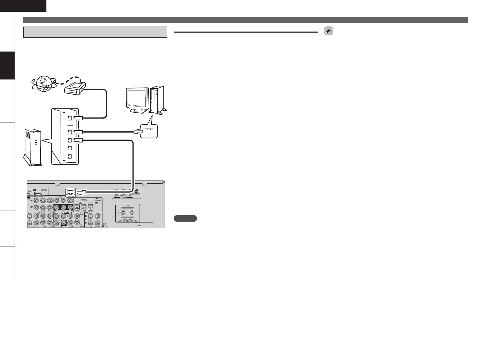
ENGLISH
Getting Started Settings Playback Remote ControlMulti-zone Information Troubleshooting Specifications
Connecting Devices
Connecting to a Home Network (LAN)
When you connect the AVR-3310 to a home network, you can enjoy
listening to music files stored on your PC, internet radio audio and
Connections
other sources. You can also control the AVR-3310 from your PC via
the Web browser.
Internet
Modem
To WAN side
To LAN port
To LAN port
Router
For connections to the Internet, contact an ISP (Internet
Service Provider) or a computer shop.
Computer
LAN port/
Ethernet
connector
Required system
Broadband Internet connection
n
Modem
n
Router
n
When using the AVR-3310, we recommend you use a router
equipped with the following functions:
Built-in DHCP server
•
This function automatically assigns IP addresses on the LAN.
Built-in 100BASE-TX switch
•
When connecting multiple devices, we recommend a switching
hub with a speed of 100 Mbps or greater.
Ethernet cable (CAT-5 or greater recommended)
n
Some flat type Ethernet cables are easily affected by noise.
We recommend using a normal type cable.
Computer
n
GRecommended systemH
OS :
•
Windows® XP Service Pack2 or later, Windows Vista
Software (Prepare one of the following.)
•
Windows Media Player ver.11
•
DLNA-compatible server software
•
Internet browser :
•
Microsoft Internet Explorer 6 or later
LAN port
•
300 MB or more free disk space
•
Operation is possible with DLNA servers other than the above,
b
but such DLNA servers are not supported. For details, check the
Web.
NOTE
A contract with an ISP is required to connect to the Internet.
•
No additional contract is needed if you already have a broadband
connection to the Internet.
The types of routers that can be used depend on the ISP. Contact an
•
ISP or a computer shop for details.
Depending on the server, video files may be displayed, but they
•
cannot be played on the AVR-3310.
If you have an Internet provider contract for a line on which network
•
settings are made manually, make the settings at “Network
Connecting” (vpage 37).
With the AVR-3310, it is possible to use the DHCP and Auto IP
•
functions to make the network settings automatically.
When using the AVR-3310 with the broadband router’s DHCP
•
function enabled, the AVR-3310 automatically performs the IP
address setting and other settings.
When using the AVR-3310 connected to a network with no DHCP
function, make the settings for the IP address, etc., at “Network
Connecting” (vpage 37).
The AVR-3310 is not compatible with PPPoE. A PPPoE-compatible
•
router is required if you have a contract for a line of the type with
which the PPPoE is set.
Depending on the ISP with which you have your contract, it may be
•
necessary to make proxy server settings to use the Internet radio
function. If you made proxy server settings on the computer to
connect to the Internet, make the proxy server settings on the AVR3310 in the same way.
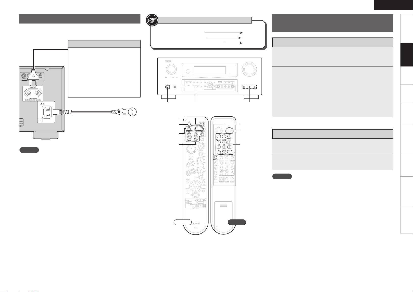
Connecting the Power Cord
[OFF]
[ON/SOURCE]
QUICK SELECT
[INPUT
SOURCE
SELECT]
QUICK SELECT<POWER><ON/STANDBY>
[MAIN OFF]
[MAIN ON]
[INPUT
SOURCE
SELECT]
Wait until all connections have been completed before connecting the
power cord.
NOTE
Insert the AC plugs securely. Incomplete connections could cause
•
noise.
Only use the AC outlet to plug in audio equipment. Do not use
•
them as power supplies for hairdryers or anything other than audio
equipment.
Connection to the AC outlet
This outlet supply power to external
•
audio equipment.
Audio equipment with a total power
•
consumption of 100 W (0.43 A) can be
connected.
The power supply turns on and off
•
together with <ON/STANDBY>. When
set to “ON”, power is supplied from
the outlet. When set to “STANDBY”,
no power is supplied.
Power cord
(included)
To household power
outlet
(AC 230 V, 50 Hz)
Symbols used to indicate buttons in this manual
Button located on both the main unit
and the remote control unit
Button only on the main unit
Button only on the remote control unit
BUTTON
<BUTTON>
[BUTTON]
ENGLISH
Once Connections are
Completed
Turning the Power On
Press <POWER>.
1
The power indicator lights red and the power is set to the
standby mode.
Press [ON/SOURCE] or <ON/STANDBY>.
2
The power indicator flashes green and the power turns on.
Also press [INPUT SOURCE SELECT] or QUICK SELECT when in
b
standby mode, the power turns on.
When [INPUT SOURCE SELECT] has been pressed, the input
source set with the [INPUT SOURCE SELECT] is set. If a QUICK
SELECT has been pressed, the input source stored in the memory
for the quick select function is set (vpage 77 “Saving Frequently
Used Settings (Quick Select Function)”).
Turning the Power Off
Press [OFF] or <ON/STANDBY>.
1
The power is set to the standby mode.
Press <POWER>.
2
The power indicator turns off, and so does the power.
NOTE
Power continues to be supplied to some of the circuitry even when
•
the power is in the standby mode. When leaving home for long
periods of time or when traveling, either press <POWER> to turn off
the power, or unplug the power cord from the power outlet.
When using ZONE2 or ZONE3, it is possible to turn the power for
•
the MAIN ZONE only on or off by pressing [MAIN ON] or [MAIN
OFF].
Getting Started Settings Playback Remote ControlMulti-zone Information Troubleshooting Specifications
Connections
Front Rear
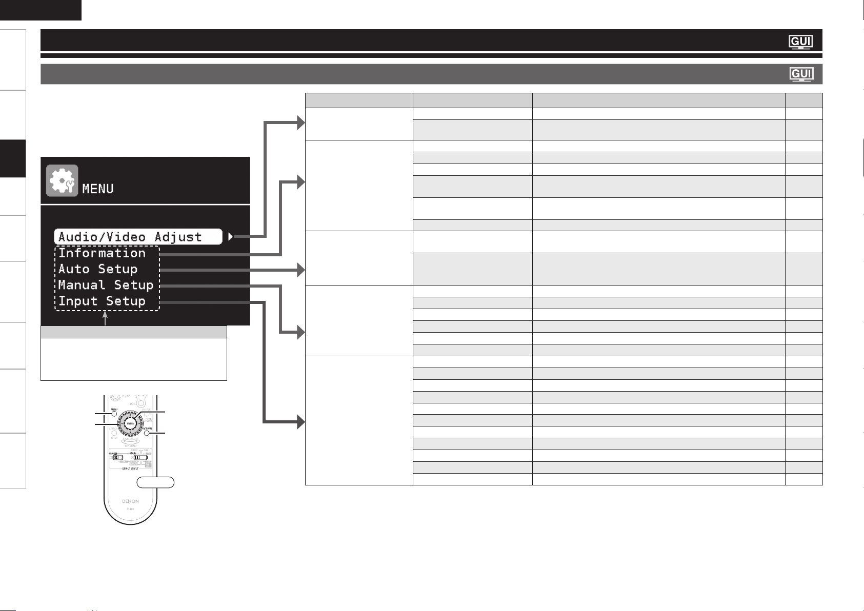
ENGLISH
RETURN
ENTER
uio p
MENU
Getting Started Connections Playback Remote ControlMulti-zone Information Troubleshooting Specifications
Settings
GUI Menu Map
Settings
Pressing MENU displays the GUI menu. From this menu, you can
move to various setting screens.
Items that only need to be set once
Set these for example upon purchase.
Once these items are set, there is no need to
set them again unless the speaker layout or the
connected speakers have been changed.
Front
Setting items Detailed items Description Page
Audio / Video Adjust
Adjust various audio and
video parameters.
Information
Show information about
receiver settings, input
signals, etc.
Auto Setup
Makes the optimum speaker
settings and corrects for the
acoustic characteristics of
the room.
Manual Setup
Use this to make various
types of detailed settings.
Input Setup
Use this to make settings
related to playing input
sources.
Audio Adjust Adjust various audio parameters. 67
Picture Adjust Adjust various video parameters. 72
Status Shows information about current settings. 73
Audio Input Signal Shows information about audio input signals. 73
HDMI Information Shows information about HDMI input/output signals and monitor. 73
Auto Surround Mode Shows information about settings stored for the auto surround
mode.
Quick Select Shows information about settings stored for the Quick Select
function.
Preset Channel Shows information about preset channels. 73
Audyssey™ Auto Setup Makes the optimum settings for the speakers being used
automatically.
Parameter Check Check Audyssey Auto Setup measurement results.
This item is only displayed after Audyssey Auto Setup procedure has
been performed.
Speaker Setup Sets the speaker size and distance, the channel level, etc. 33
HDMI Setup Make settings for HDMI video/audio output. 35
Audio Setup Make settings for audio playback. 36
Network Setup Make network settings. 37
Zone Setup Make settings for audio playback in the multi-zone system. 39
Option Setup Make various other settings. 40
Auto Preset Use the auto preset function to program radio stations. 49
Preset Skip
Preset Name Assign name to a preset memory. 49
Input Assign Change input connector assignment. 44
Video Makes the video settings. 46
Input Mode Sets the audio input mode and decode mode. 47
Rename Change the display name for this source. 48
Source Level Adjust the playback level of the audio input. 48
Playback Mode (for iPod) Make settings for “iPod” playback. 48
Playback Mode (for NET/USB) Make settings for “NET/USB” playback. 49
Still Picture Make settings for still picture playback. 49
Set the preset memories that you do not want to display when tuning.
73
73
27
32
49
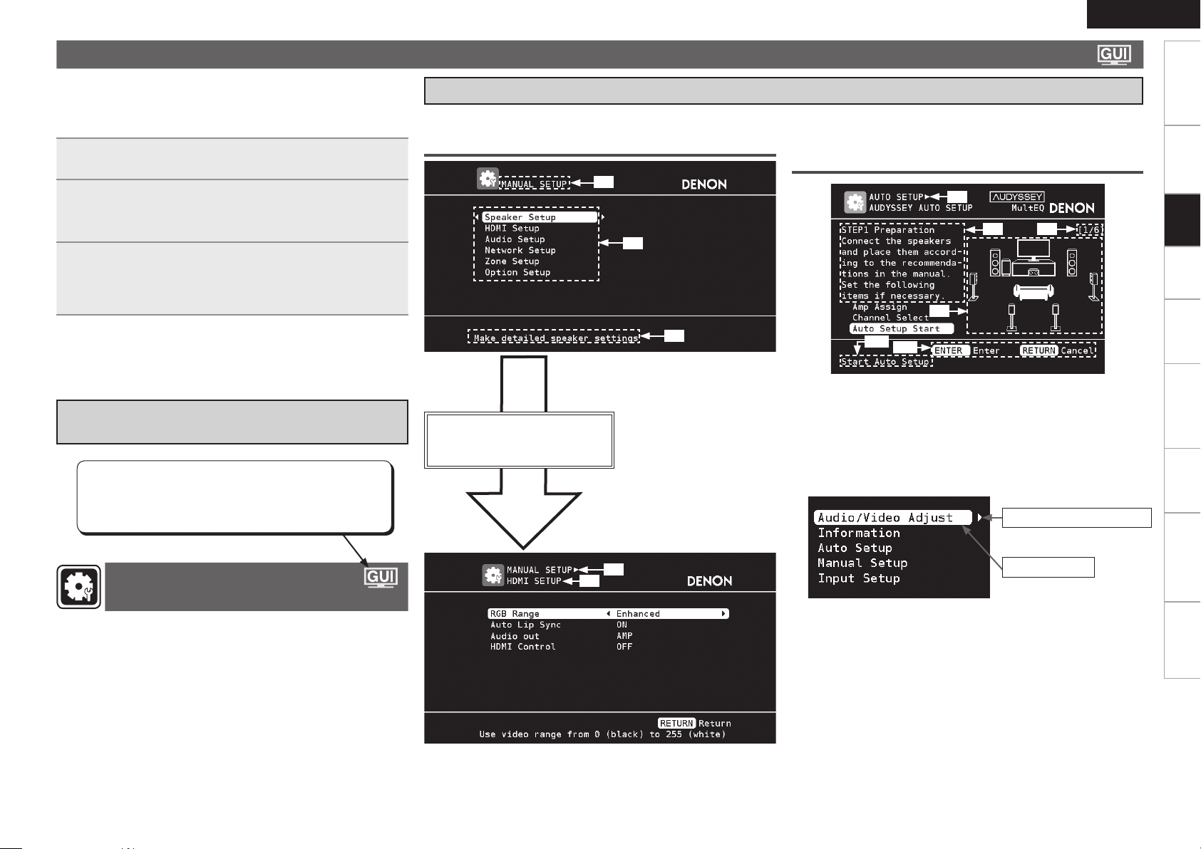
GUI Menu Operation
When a TV is connected to the AVR-3310, the GUI menu, sound field
parameters, etc., can be displayed on the TV.
This allows you to operate the AVR-3310 and make settings on it while
looking at the GUI menu displayed on the TV.
ENGLISH
Getting Started Connections Playback Remote ControlMulti-zone Information Troubleshooting Specifications
Examples of GUI Menu Screen Displays
Typical examples are described below.
Press MENU.
1
The GUI menu is displayed on the TV screen.
Press uiop to select the menu to be set or
2
operated.
To return to the previous item, press o or RETURN.b
Press RETURN to enter the setting.
3
Select “Default”, then press ENTER to reset to the default
b
setting.
Exiting the GUI Menu
n
Press MENU while the GUI menu is displayed.
The GUI menu display disappears.
Example of the Display of the GUI Mark
at a Title
Items for which this mark is indicated at the title can be
operated from the GUI.
We recommend performing such operations from the
GUI.
GExample 1H Menu selection screen GExample 2H Audyssey Auto Setup screen
(with illustration)
z1
z6
z1 : Currently selected setup item
z2 : List of currently selected setup items
z3 : Guide text for the currently selected
Press i to select “HDMI Setup”
and then press p.
(Or press ENTER.)
z2
setup item
z3
z10
z7
z9
z11
z6 : History item
z7 : Operation guidance text
z8 : Operation step
z9 : Illustration
z10 : Guide text for the currently selected
setup item
z11 : Operation button guidance
z8
Listn
Switch to the next item
(Use p or ENTER to switch.)
Settings
Making Detailed Settings
(Manual Setup)
z4
z5
z4 : History item
z5 : Currently selected setup item
Selected item
Switch the selected
b
item using ui.
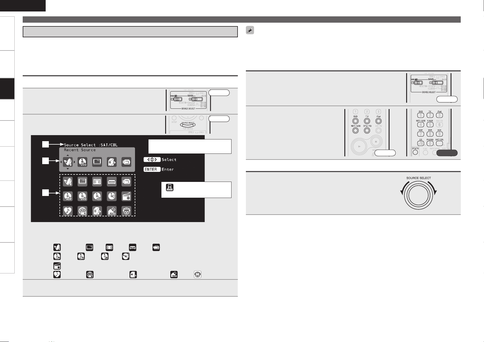
ENGLISH
Getting Started Connections Playback Remote ControlMulti-zone Information Troubleshooting Specifications
GUI Menu Operation
Selecting the Input Source
There are three ways to select the input source, as described below.
q Selecting the input source using the Source Select menu (GUI menu)
w Selecting the input source using the [INPUT SOURCE SELECT] (Main remote control unit)
e Selecting the input source using the <SOURCE SELECT> (Main unit)
q Using the Source Select Menu
Settings
The input source can also be selected using the source selection menu.
Set [DEVICE SELECT 1] to “MAIN/TV” and
1
[DEVICE SELECT 2] to “MAIN”.
Press [SOURCE SELECT].
2
Display the “Source Select” menu.
q
w
e
Front
Front
The currently selected input source
is highlighted.
“ ” is displayed when using
a control dock for iPod.
Input sources that are not going to be used can be set ahead of time. Make this setting at “Source
•
Delete” (vpage 40).
To turn off the source selection menu without selecting an input source, press [SOURCE SELECT]
•
again.
w Operating on the Main Remote Control Unit
Set [DEVICE SELECT 1] to “MAIN/TV” and [DEVICE
1
SELECT 2] to “MAIN”.
Front
Press [INPUT SOURCE SELECT].
2
The desired input source can be
selected directly.
Front Rear
e Operating on the Main Unit
Turn <SOURCE SELECT>.
b If “ZONE2/3/ Rec Select”, “Video Select” or “Tuning Preset”
mode is selected for the input source, press <SOURCE>
before turning the <SOURCE SELECT>.
q Input Source : The name of the highlighted input source is displayed.
w Recently used sources : The recently used input sources (up to 5) are displayed.
e Icons for the input sources in the different categories are displayed.
Video :
Player :
Tuner :
Network :
(SAT/CBL), (TV), (VCR), (DVR), (V.AUX)
(HDP), (DVD), (CD), (PHONO)
(FM/AM)
(Favorites), (Internet Radio), (Media Server), (USB), (Napster)
Use uio p to select the input source icon, then press ENTER.
3
The input source is set and the source selection menu is turned off.
 Loading...