

Page 1
AV SURROUND RECEIVER
AVR-1905
OPERATING INSTRUCTIONS
BEDIENUNGSANLEITUNG
MODE D’EMPLOI
ISTRUZIONI PER L’USO
INSTRUCCIONES DE OPERACION
GEBRUIKSAANWIJZING
BRUKSANVISNING
FOR ENGLISH READERS PAGE 112 ~ PAGE 141
FÜR DEUTSCHE LESER SEITE 142 ~ SEITE 180
POUR LES LECTEURS FRANCAIS PAGE 181 ~ PAGE 119
PER IL LETTORE ITALIANO PAGINA 120 ~ PAGINA 158
PARA LECTORES DE ESPAÑOL PAGINA 159 ~ PAGINA 197
VOOR NEDERLANDSTALIGE LEZERS PAGINA 198 ~ PAGINA 236
FOR SVENSKA LÄSARE SIDA 237 ~ SIDA 275
Page 2
ENGLISH
DEUTSCH FRANCAIS ITALIANO ESPAÑOL NEDERLANDS SVENSKA
CAUTION: TO REDUCE THE RISK OF ELECTRIC SHOCK, DO
WARNING: TO REDUCE THE RISK OF FIRE OR ELECTRIC SHOCK, DO
• DECLARATION OF CONFORMITY
We declare under our sole responsibility that this product,
to which this declaration relates, is in conformity with the
following standards:
EN60065, EN55013, EN55020, EN61000-3-2 and EN610003-3.
Following the provisions of 73/23/EEC, 89/336/EEC and
93/68/EEC Directive.
• ÜBEREINSTIMMUNGSERKLÄRUNG
Wir erklären unter unserer Verantwortung, daß dieses
Produkt, auf das sich diese Erklärung bezieht, den
folgenden Standards entspricht:
EN60065, EN55013, EN55020, EN61000-3-2 und EN610003-3.
Entspricht den Verordnungen der Direktive 73/23/EEC,
89/336/EEC und 93/68/EEC.
• DECLARATION DE CONFORMITE
Nous déclarons sous notre seule responsabilité que
l’appareil, auquel se réfère cette déclaration, est conforme
aux standards suivants:
EN60065, EN55013, EN55020, EN61000-3-2 et EN610003-3.
D’après les dispositions de la Directive 73/23/EEC,
89/336/EEC et 93/68/EEC.
• DICHIARAZIONE DI CONFORMITÀ
Dichiariamo con piena responsabilità che questo prodotto,
al quale la nostra dichiarazione si riferisce, è conforme
alle seguenti normative:
EN60065, EN55013, EN55020, EN61000-3-2 e EN610003-3.
In conformità con le condizioni delle direttive 73/23/EEC,
89/336/EEC e 93/68/EEC.
QUESTO PRODOTTO E’ CONFORME
AL D.M. 28/08/95 N. 548
CAUTION
RISK OF ELECTRIC SHOCK
DO NOT OPEN
NOT REMOVE COVER (OR BACK). NO USER
SERVICEABLE PARTS INSIDE. REFER SERVICING
TO QUALIFIED SERVICE PERSONNEL.
The lightning flash with arrowhead symbol, within an equilateral triangle,
is intended to alert the user to the presence of uninsulated “dangerous
voltage” within the product’s enclosure that may be of sufficient
magnitude to constitute a risk of electric shock to persons.
The exclamation point within an equilateral triangle is intended to alert the
user to the presence of important operating and maintenance (servicing)
instructions in the literature accompanying the appliance.
NOT EXPOSE THIS APPLIANCE TO RAIN OR MOISTURE.
• DECLARACIÓN DE CONFORMIDAD
Declaramos bajo nuestra exclusiva responsabilidad que
este producto al que hace referencia esta declaración,
está conforme con los siguientes estándares:
EN60065, EN55013, EN55020, EN61000-3-2 y EN610003-3.
Siguiendo las provisiones de las Directivas 73/23/EEC,
89/336/EEC y 93/68/EEC.
• EENVORMIGHEIDSVERKLARING
Wij verklaren uitsluitend op onze verantwoordelijkheid
dat dit produkt, waarop deze verklaring betrekking heeft,
in overeenstemming is met de volgende normen:
EN60065, EN55013, EN55020, EN61000-3-2 en EN610003-3.
Volgens de bepalingen van de Richtlijnen 73/23/EEC,
89/336/EEC en 93/68/EEC.
• ÖVERENSSTÄMMELSESINTYG
Härmed intygas helt på eget ansvar att denna produkt,
vilken detta intyg avser, uppfyller följande standarder:
EN60065, EN55013, EN55020, EN61000-3-2 och EN610003-3.
Enligt stadgarna i direktiv 73/23/EEC, 89/336/EEC och
93/68/EEC.
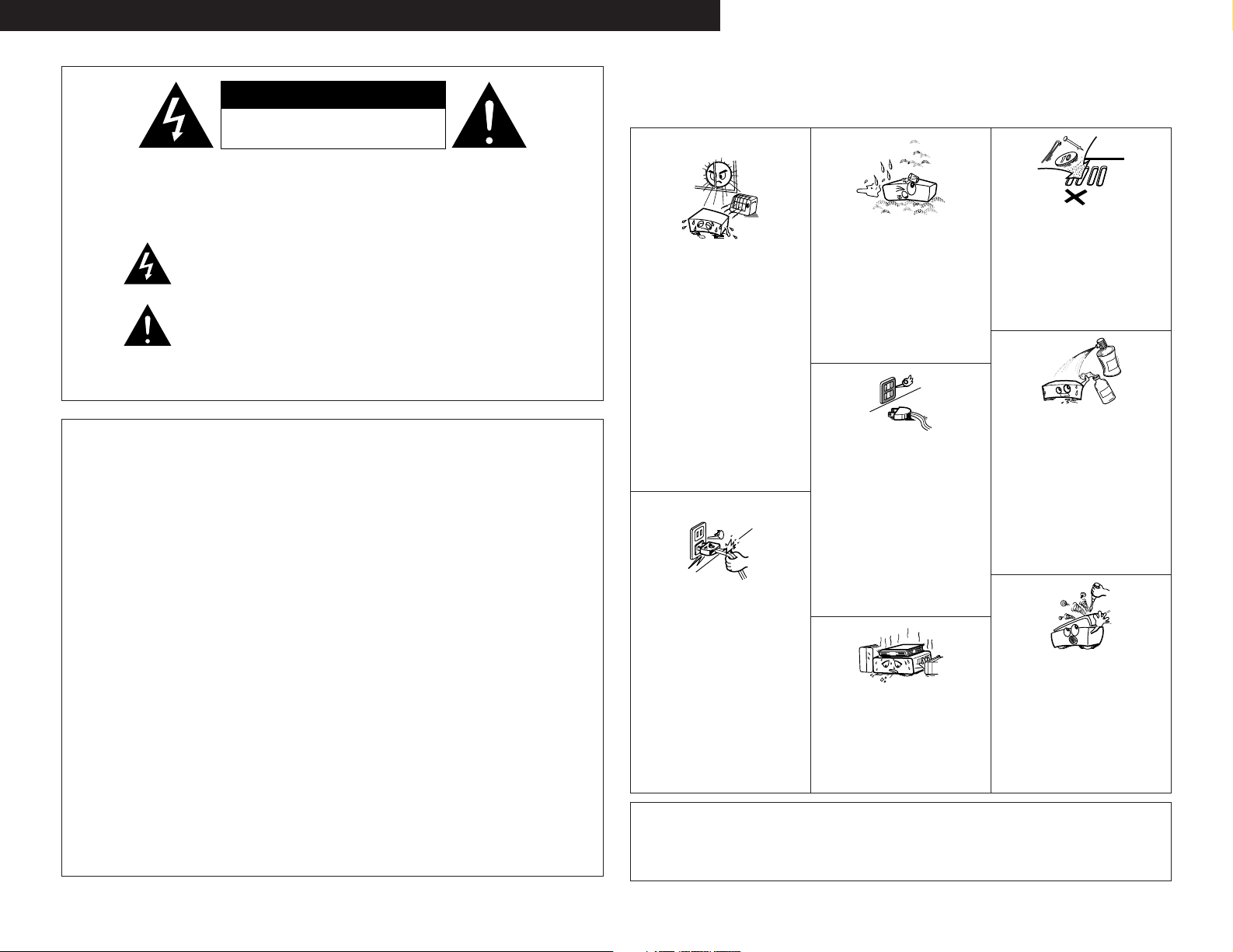
NOTE ON USE / HINWEISE ZUM GEBRAUCH /
OBSERVATIONS RELATIVES A L’UTILISATION / NOTE SULL’USO
NOTAS SOBRE EL USO / ALVORENS TE GEBRUIKEN / OBSERVERA
• Do not let foreign objects in the set.
• Keep the set free from moisture, water, and
dust.
• Halten Sie das Gerät von Feuchtigkeit,
Wasser und Staub fern.
• Avoid high temperatures.
Allow for sufficient heat dispersion when
installed on a rack.
• Vermeiden Sie hohe Temperaturen.
Beachten Sie, daß eine ausreichend
Luftzirkulation gewährleistet wird, wenn das
Gerät auf ein Regal gestellt wird.
• Eviter des températures élevées
Tenir compte d’une dispersion de chaleur
suffisante lors de l’installation sur une étagère.
• Evitate di esporre l’unità a temperature alte.
Assicuratevi che ci sia un’adeguata dispersione
del calore quando installate l’unità in un
mobile per componenti audio.
• Evite altas temperaturas
Permite la suficiente dispersión del calor
cuando está instalado en la consola.
• Vermijd hoge temperaturen.
Zorg voor een degelijk hitteafvoer indien het
apparaat op een rek wordt geplaatst.
• Undvik höga temperaturer.
Se till att det finns möjlighet till god
värmeavledning vid montering i ett rack.
• Handle the power cord carefully.
Hold the plug when unplugging the cord.
• Gehen Sie vorsichtig mit dem Netzkabel um.
Halten Sie das Kabel am Stecker, wenn Sie
den Stecker herausziehen.
• Manipuler le cordon d’alimentation avec
précaution.
Tenir la prise lors du débranchement du cordon.
• Manneggiate il filo di alimentazione con cura.
Agite per la spina quando scollegate il cavo
dalla presa.
• Maneje el cordón de energía con cuidado.
Sostenga el enchufe cuando desconecte el
cordón de energía.
• Hanteer het netsnoer voorzichtig.
Houd het snoer bij de stekker vast wanneer
deze moet worden aan- of losgekoppeld.
• Hantera nätkabeln varsamt.
Håll i kabeln när den kopplas från el-uttaget.
CAUTION
• The ventilation should not be impeded by covering the
ventilation openings with items, such as newspapers,
table-cloths, curtains, etc.
• No naked flame sources, such as lighted candles, should
be placed on the apparatus.
• Protéger l’appareil contre l’humidité, l’eau et
lapoussière.
• Tenete l’unità lontana dall’umidità, dall’acqua
e dalla polvere.
• Mantenga el equipo libre de humedad, agua
y polvo.
• Laat geen vochtigheid, water of stof in het
apparaat binnendringen.
• Utsätt inte apparaten för fukt, vatten och
damm.
• Unplug the power cord when not using the
set for long periods of time.
• Wenn das Gerät eine längere Zeit nicht
verwendet werden soll, trennen Sie das
Netzkabel vom Netzstecker.
• Débrancher le cordon d’alimentation lorsque
l’appareil n’est pas utilisé pendant de
longues périodes.
• Disinnestate il filo di alimentazione quando
avete l’intenzione di non usare il filo di
alimentazione per un lungo periodo di tempo.
• Desconecte el cordón de energía cuando no
utilice el equipo por mucho tiempo.
• Neem altijd het netsnoer uit het stopkontakt
wanneer het apparaat gedurende een lange
periode niet wordt gebruikt.
• Koppla ur nätkabeln om apparaten inte
kommer att användas i lång tid.
* (For sets with ventilation holes)
• Do not obstruct the ventilation holes.
• Die Belüftungsöffnungen dürfen nicht verdeckt
werden.
• Ne pas obstruer les trous d’aération.
• Non coprite i fori di ventilazione.
• No obstruya los orificios de ventilación.
• De ventilatieopeningen mogen niet worden
beblokkeerd.
• Täpp inte till ventilationsöppningarna.
• Please be care the environmental aspects of battery
disposal.
• The apparatus shall not be exposed to dripping or
splashing for use.
• No objects filled with liquids, such as vases, shall be
placed on the apparatus.
• Keine fremden Gegenstände in das Gerät
kommen lassen.
• Ne pas laisser des objets étrangers dans
l’appareil.
• E’ importante che nessun oggetto è inserito
all’interno dell’unità.
• No deje objetos extraños dentro del equipo.
• Laat geen vreemde voorwerpen in dit
apparaat vallen.
• Se till att främmande föremål inte tränger in i
apparaten.
• Do not let insecticides, benzene, and thinner
come in contact with the set.
• Lassen Sie das Gerät nicht mit Insektiziden,
Benzin oder Verdünnungsmitteln in Berührung
kommen.
• Ne pas mettre en contact des insecticides,
du benzène et un diluant avec l’appareil.
• Assicuratevvi che l’unità non venga in contatto
con insetticidi, benzolo o solventi.
• No permita el contacto de insecticidas, gasolina
y diluyentes con el equipo.
• Laat geen insektenverdelgende middelen,
benzine of verfverdunner met dit apparaat in
kontakt komen.
• Se till att inte insektsmedel på spraybruk,
bensen och thinner kommer i kontakt med
apparatens hölje.
• Never disassemble or modify the set in any
way.
• Versuchen Sie niemals das Gerät auseinander
zu nehmen oder auf jegliche Art zu verändern.
• Ne jamais démonter ou modifier l’appareil
d’une manière ou d’une autre.
• Non smontate mai, nè modificate l’unità in
nessun modo.
• Nunca desarme o modifique el equipo de
ninguna manera.
• Nooit dit apparaat demonteren of op andere
wijze modifiëren.
• Ta inte isär apparaten och försök inte bygga
om den.
2
Page 3
ENGLISH
2 We greatly appreciate your purchase of the AVR-1905.
2 To be sure you take maximum advantage of all the features the AVR-1905 has to offer, read these
instructions carefully and use the set properly. Be sure to keep this manual for future reference,
should any questions or problems arise.
“SERIAL NO.
PLEASE RECORD UNIT SERIAL NUMBER ATTACHED TO THE REAR OF THE
CABINET FOR FUTURE REFERENCE”
2 INTRODUCTION
Thank you for choosing the DENON AVR-1905 Digital A / V Surround Receiver. This remarkable component has
been engineered to provide superb surround sound listening with home theater sources such as DVD, as well as
providing outstanding high fidelity reproduction of your favorite music sources.
As this product is provided with an immense array of features, we recommend that before you begin hookup and
operation that you review the contents of this manual before proceeding.
TABLE OF CONTENTS
Before Using........................................................3
z
Cautions on Installation........................................3
x
Cautions on Handling...........................................3
c
Features...............................................................4
v
Connections ..................................................5 ~ 9
b
Part Names and Functions ............................9, 10
n
Using the Remote Control Unit .........................10
m
Setting up the System ..............................11 ~ 16
,
Remote Control Unit .................................17 ~ 19
.
Operation...................................................19 ~ 23
⁄0
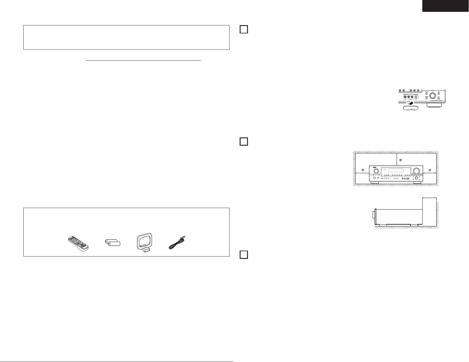
ACCESSORIES
2
Check that the following parts are included in addition to the main unit:
q Operating instructions........................................1
w Service station list..............................................1
e Remote control unit (RC-979) ............................1
e
rt y
Surround....................................................23 ~ 28
⁄1
DSP Surround Simulation..........................28 ~ 30
⁄2
Listening to the Radio ...............................31 ~ 35
⁄3
Last Function Memory.......................................35
⁄4
Initialization of the Microprocessor....................35
⁄5
Additional Information ...............................35 ~ 39
⁄6
Troubleshooting .................................................40
⁄7
Specifications.....................................................41
⁄8
List of Preset Codes ....................................276 ~ 278
r R6P/AA batteries................................................2
t AM loop antenna................................................1
y FM indoor antenna.............................................1
1
BEFORE USING
Pay attention to the following before using this unit:
• Moving the set
To prevent short circuits or damaged wires in the
connection cords, always unplug the power cord
and disconnect the connection cords between all
other audio components when moving the set.
• Before turning the power switch on
Check once again that all connections are proper
and that there are not problems with the connection
cords. Always set the power switch to the standby
position before connecting and disconnecting
connection cords.
2
CAUTIONS ON INSTALLATION
Noise or disturbance of the picture may be generated
if this unit or any other electronic equipment using
microprocessors is used near a tuner or TV.
If this happens, take the following steps:
• Install this unit as far as possible from the tuner or
TV.
• Set the antenna wires from the tuner or TV away
from this unit’s power cord and input/output
connection cords.
• Noise or disturbance tends to occur particularly
when using indoor antennas or 300 Ω/ohms feeder
wires. We recommend using outdoor antennas
and 75 Ω/ohms coaxial cables.
For heat dispersal, leave at least 10 cm of space
between the top, back and sides of this unit and
the wall or other components.
• Store this instructions in a safe place
After reading, store this instructions along with the
warranty in a safe place.
• Note that the illustrations in this instructions
may differ from the actual set for explanation
purposes.
• V. AUX terminal
The AVR-1905’s front
panel is equipped with
a V. AUX terminal.
Remove the cap
covering the terminal
when you want to use
it.
10 cm or more
10 cm or more
Wall
3
CAUTIONS ON HANDLING
• Switching the input function when input jacks
are not connected
A clicking noise may be produced if the input
function is switched when nothing is connected to
the input jacks. If this happens, either turn down the
MASTER VOLUME control or connect components
to the input jacks.
• Muting of PRE OUT jacks, HEADPHONE jack and
SPEAKER terminals
The PRE OUT jacks, HEADPHONE jack and SPEAKER
terminals include a muting circuit.
Because of this, the output signals are greatly
reduced for several seconds after the power switch
is turned on or input function, surround mode or any
other-set-up is changed. If the volume is turned up
during this time, the output will be very high after the
muting circuit stops functioning. Always wait until
the muting circuit turns off before adjusting the
volume.
• Whenever the unit is in the STANDBY state, the
apparatus is still connected on AC line voltage.
Please be sure to turn the power off (
you leave home for, say, a vacation.
£off) when
3
Page 4

ENGLISH
4
FEATURES
1. Dolby Digital
Using advanced digital processing algorithms,
Dolby Digital provides up to 5.1 channels of widerange, high fidelity surround sound. Dolby Digital is
the default digital audio delivery system for DVD
and North American DTV.
2. Dolby Pro Logic
Dolby Pro Logic
technology of Dolby Pro Logic
signals recorded on two channels into up to 7.1
playback channels, including the surround back
channel. Dolby Pro Logic
channel sources to be played in up to 7.1 channels.
The mode can be selected according to the source.
The Music mode is best suited for playing
music,the Cinema mode for playing movies, and
the Game mode for playing games. The Game
mode can only be used with 2-channel audio
sources.
3. Dolby Pro Logic
In addition to the previously offered Music and
Cinema modes, the AVR-1905 also offers a Game
mode optimum for games.
4. DTS (Digital Theater Systems)
DTS provides up to 5.1 channels of wide-range,
high fidelity surround sound, from sources such as
laser disc, DVD and specially-encoded music discs.
5. DTS-ES Extended Surround and DTS Neo:6
The AVR-1905 can be decoded with DTS-ES
Extended Surround, a multi-channel format
developed by Digital Theater Systems Inc.
The AVR-1905 can be also decoded with DTS
Neo:6, a surround mode allowing 6.1 channels
playback of regular stereo sources.
6. DTS 96/24 compatibility
The AVR-1905 can be decoded with sources recorded
in DTS 96/24, a multi-channel digital signal format
developed by Digital Theater Systems Inc.
DTS 96/24 sources can be played in the multichannel mode on the AVR-1905 with high sound
quality of 96 kHz/24 bits or 88.2 kHz/24 bits.
IIx compatibility
IIx furthers the matrix decording
II to decode audio
IIx also allows 5.1-
II Game mode compatibility
7. Future Sound Format Upgrade Capability via
Eight Channel Outputs
For future multi-channel audio format(s), the AVR1905 is provided with 5.1 channel (five main
channels, plus one low frequency effects channel)
inputs, along with a full set of 7.1 channel pre-amp
outputs, controlled by the 8 channel master
volume control. This assures future upgrade
possibilities for any future multi-channel sound
format.
8. Front input Terminal
The unit is equipped with a Front Input connector
for the convenient connection of a video camera
or other equipment.
9. Video Conversion Function
The AVR-1905 is equipped with a function for
converting the signals input to the video input
connector and S-Video input connector. With this
function, the AVR-1905’s monitor out connector
and the monitor (TV) can be connected with video
pin-plug cords or an S-Video connection cord.
10. Component Video Switching
In addition to composite video and “S” video
switching, the AVR-1905 provides 3 sets of
component video (Y, P
set of component video outputs to the television,
for superior picture quality.
11. Auto Surround Mode
This function stores the surround mode last used
for an input signal in the memory and automatically
sets that surround mode the next time that signal
is input.
12. Preset Memory Tuning
56-Station AM/FM Random Preset Memory tuning.
13. On Screen Diaplay
Troublesome operations such as adjusting the
delay time and other parameters according to the
listening environment are greatly simplified. The
various parameters can be set simply by selecting
the graphic displayed on the monitor screen
according to the listening room’s system
environment.
B/C
R) inputs, and one
B, PR/C
4
Page 5
5
R
OUTPUT INPUT
LRL
L
R
R
OUTPUT
L
R
L
DIGITAL AUDIODIGITAL AUDIO
B
OPTICAL
OUTPUT
COAXIAL
DIGITAL AUDIODIGITAL AUDIO
B
L
R
L
R
RLR
L
INPUT
OPTICAL
OUTPUT
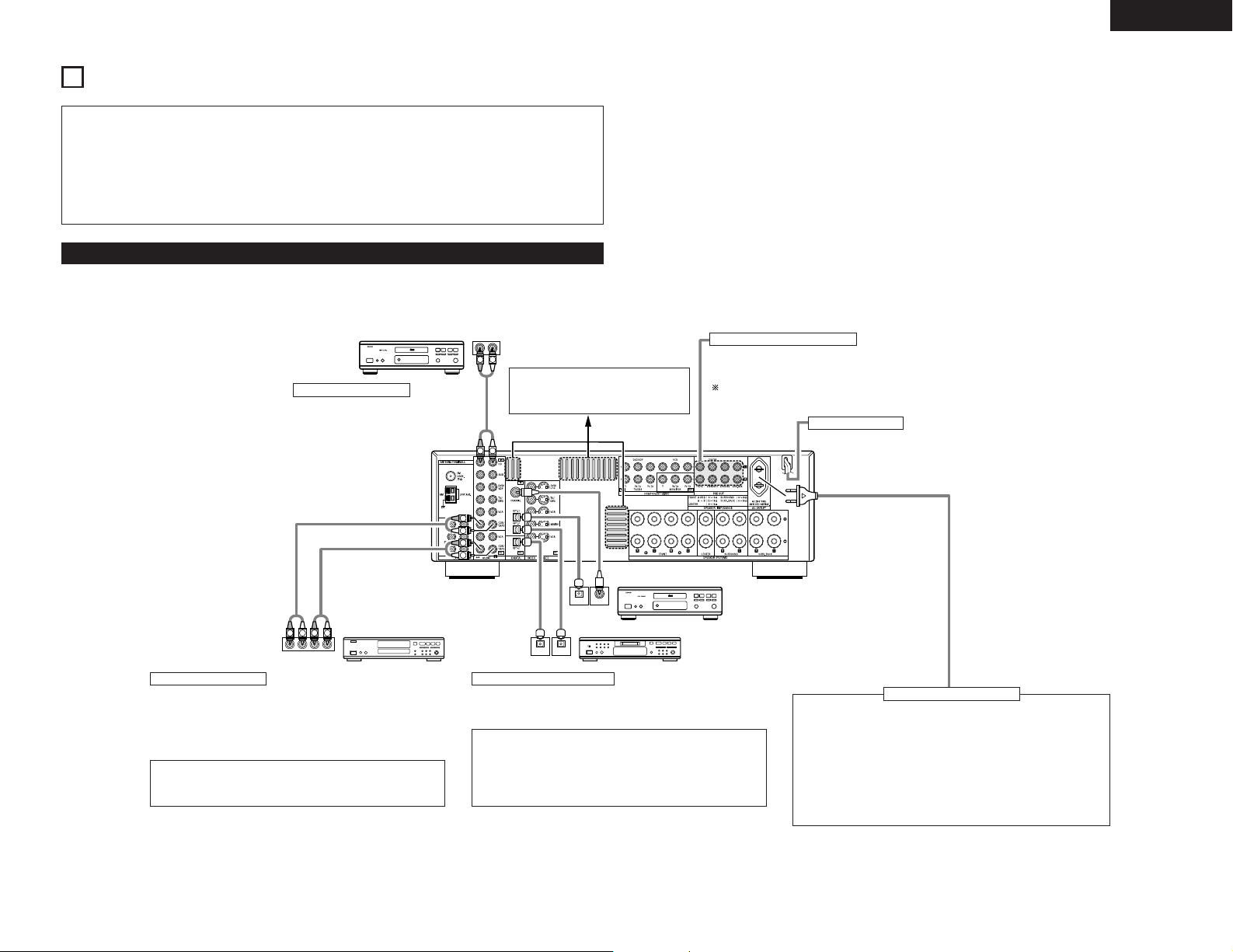
CONNECTIONS
ENGLISH
• Do not plug in the AC cord until all connections
have been completed.
• Be sure to connect the left and right channels
properly (left with left, right with right).
• Insert the plugs securely. Incomplete connections
will result in the generation of noise.
• Use the AC OUTLET for audio equipment only.
• Note that binding pin plug cords together with AC
cords or placing them near a power transformer
will result in generating hum or other noise.
• Noise or humming may be generated if a
connected audio equipment is used independently
without turning the power of this unit on. If this
happens, turn on the power of the this unit.
Do not use them for hair driers, etc.
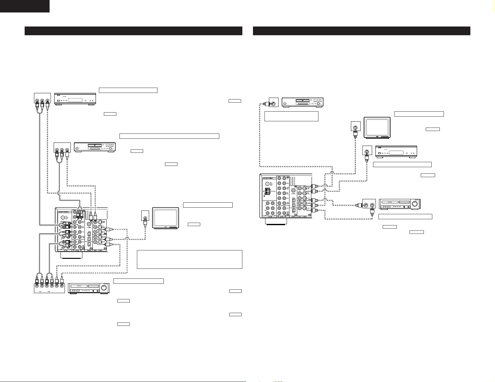
Connecting the audio components
• When making connections, also refer to the operating instructions of the other components.
CD player
Connecting a CD player
Connect the CD player’s analog output
jacks (ANALOG OUTPUT) to this unit’s
CD jacks using pin plug cords.
Route the connection cords, etc., in
such a way that they do not obstruct
the ventilation holes.
Connecting the PRE OUT jacks
Use these jacks if you wish to connect external power amplifier(s)
to increase the power of the front, center and surround sound
channels, or for connection to powered loudspeakers.
To use Surround back with one speaker, connect the speaker
to SURR. BACK L CH.
Power supply cord
AC 230V, 50Hz
CD recorder or
Tape deck
Connecting a tape deck
Connections for recording:
Connect the tape deck’s recording input jacks (LINE IN or REC) to this
unit’s tape recording (CDR/TAPE OUT) jacks using pin plug cords.
Connections for playback:
Connect the tape deck’s playback output jacks (LINE OUT or PB) to this
unit’s tape playback (CDR/TAPE IN) jacks using pin plug cords.
NOTE:
If humming noise is generated by a tape deck, etc., move the tape
deck away.
CD player or other component equipped
with digital output jacks
MD recorder, CD recorder or other component
equipped with digital input/output jack
Connecting the DIGITAL jacks
Use these for connections to audio (video) equipment with digital
output.
Refer to page 15 for instructions on setting this terminal.
NOTES:
• Use 75 Ω/ohms cable pin cords for coaxial connections.
• Use optical cables for optical connections, removing the cap
before connecting.
• The main unit’s power must be turned on when recording via the
AVR-1905.
AC OUTLET
• SWITCHED (total capacity – 100 W)
The power to these outlets is turned on and off in conjunction with
the POWER operation switch on the main unit, and when the power
is switched between on and standby from the remote control unit.
No power is supplied from these outlets when this unit’s power is at
standby. Never connect equipment whose total capacity is above 100
W.
NOTE:
Only use the AC OUTLET for audio equipment. Never use them for
hair driers, TVs or other electrical appliances.
Connecting the AC OUTLET
5
Page 6
ENGLISH
IN
VIDEO
R IN OUT
AUDIO
VIDEO
OUT IN
LRL
RLR
L
R OUT
VIDEO
OUT
L
AUDIO
L
R
R OUT
VIDEO
OUT
L
AUDIO
R
L
R
L
R
L
R
L
B
B
L
R
IN
S-VIDEO
OUT
S-VIDEO
OUT
S-VIDEO
OUT IN
S-VIDEO
VIDEO IN
VIDEO OUT
VIDEO IN
VIDEO OUT
VIDEO OUT
B
B
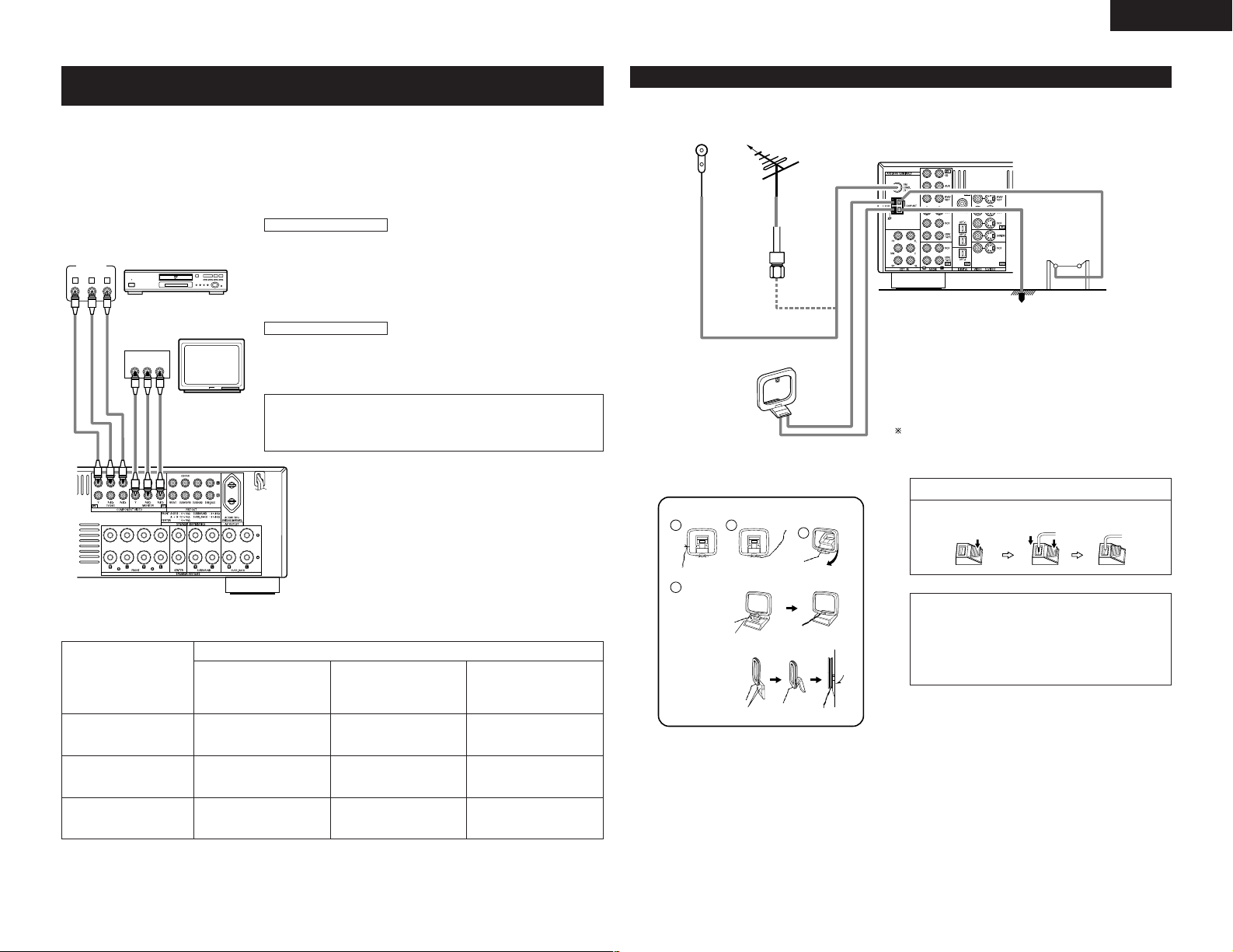
Connecting the video components
• To connect the video signal, connect using a 75 Ω/ohms video signal cable cord. Using an improper cable can
result in a drop in video quality.
• When making connections, also refer to the operating instructions of the other components.
• The AVR-1905 is equipped with a function for up-converting video signals.
• The signal connected to the video signal terminal is output to the S-Video monitor out terminals.
• The REC OUT terminals have no conversion function, so when recording only connect the video terminals.
TV or DBS tuner
DVD player or
video disc player (VDP), etc.
Connecting a TV or DBS tuner
TV or DBS
• Connect the TV’s or DBS tuner’s video output jack (VIDEO OUTPUT) to the
(yellow) TV or DBS IN jack using a 75 Ω/ohms video coaxial pin plug cord.
• Connect the TV’s or DBS tuner’s audio output jacks (AUDIO OUTPUT) to the
AUDIO
TV or DBS IN jacks using pin plug cords.
Connecting a DVD player or a video disc player (VDP)
DVD or VDP
• Connect the video disc player’s video output jack (VIDEO OUTPUT) to
VIDEO
the (yellow) DVD IN jack using a 75 Ω/ohms video coaxial pin
plug cord.
• Connect the video disc player’s analog audio output jacks (ANALOG
AUDIO OUTPUT) to the DVD IN jacks using pin plug cords.
• VDP can be connected to the VDP jacks in the same way.
AUDIO
Monitor TV
Connecting a monitor TV
MONITOR OUT
• Connect the TV’s video input
jack (VIDEO INPUT) to the
VIDEO
MONITOR OUT jack
using a 75 Ω/ohms video coaxial
pin plug cord.
VIDEO
Connecting the video components equipped with S-Video jacks
• When making connections, also refer to the operating instructions of the other components.
• A note on the S input jacks
The input selectors for the S inputs and pin jack inputs work in conjunction with each other.
• The AVR-1905 is equipped with a function for converting video signals.
• The signal connected to the S-Video signal terminal is output to the composite video monitor out terminals.
• The REC OUT terminals have no conversion function, so when recording only connect the S-Video terminals.
DVD player or
video disc player (VDP)
Connecting a DVD player or
a video disc player (VDP)
DVD or VDP
• Connect the DVD player’s S-Video output jack
to the S-VIDEO DVD IN jack using a S-Video
connection cord.
• VDP can be connected to the VDP jacks in the
same way.
• It is also possible to connect a video disc player,
DVD player, video camcorder, game machine,
etc., to the V.AUX jacks.
Monitor TV
Connecting a TV or DBS tuner
• Connect the TV’s or DBS tuner’s S video output jack (SVIDEO OUTPUT) to the TV or DBS IN jack
using an S-Video connection cord.
Connecting a monitor TV
MONITOR OUT
• Connect the TV’s S video input (S-VIDEO
INPUT) to the MONITOR OUT
jack using a S jack connection cord.
S-VIDEO
TV or
satellite broadcast tuner
S-VIDEO
Video deck
Connecting the video decks
• Connect the video deck’s S output jack (S-OUT) to the
S-VIDEO
VCR IN jack and the video deck’s S input
jack (S-IN) to the VCR OUT jack using S-Video
connection cords.
S-VIDEO
6
Connecting a video decks
Video input/output connections:
• Connect the video deck’s video output jack (VIDEO OUT) to the
(yellow) VCR IN jack, and the video deck’s video input jack (VIDEO IN) to the
VIDEO
cords.
Connecting the audio output jacks:
• Connect the video deck’s audio output jacks (AUDIO OUT) to the
VCR IN jacks, and the video deck’s audio input jacks (AUDIO IN) to the
AUDIO
Video deck
Note on connecting the digital input jacks
• Only audio signals are inputs to the digital input jacks.
For details. (See page 5)
(yellow) VCR OUT jack using 75 Ω/ohms video coaxial pin plug
VCR OUT jacks using pin plug cords.
VIDEO
AUDIO
Page 7
ENGLISH
1
4
2
3
VIDEO OUT
Y
CRCB
COMPONENT
YCRCB
VIDEO IN
COMPONENT
B
Connecting the video component equipped with Color Difference
(Component - Y, P
• When making connections, also refer to the operating instructions of the other components.
• The signals input to the color difference (component) video jacks are not output from the VIDEO output jack
(yellow) or the S-Video output jack. In addition, the video signals input to the VIDEO input (yellow) and S-Video
input jacks are not output to the color difference (component) video jacks.
• Some video sources with component video outputs are labeled Y, C
terms all refer to component video color difference output.
DVD player
R/CR
, PB/CB) Video jacks
Connecting a DVD player
DVD IN jacks
• Connect the DVD player’s color difference (component) video output jacks
• In the same way, another video source with component video outputs such as
Monitor TV
Connecting a monitor TV
MONITOR OUT jack
• Connect the TV’s color difference (component) video input jacks (COMPONENT
B, CR, or Y, PB, PR, or Y, R-Y, B-Y. These
(COMPONENT VIDEO OUTPUT) to the COMPONENT DVD/VDP IN jack using
75 Ω/ohms coaxial video pin-plug cords.
a TV/DBS tuner, etc., can be connected to the TV/DBS color difference
(component) video jacks.
VIDEO INPUT) to the COMPONENT MONITOR OUT jack using 75 Ω/ohms
coaxial video pin-plug cords.
• The color difference input jacks may be indicated differently on some TVs,
monitors or video components (“C
and Y”, etc.). For details, carefully read the operating instructions included
with the TV or other component.
R, CB and Y”, “R-Y, B-Y and Y”, “PR, PB
Connecting the antenna terminals
DIRECTION OF
BROADCASTING
STATION
FM INDOOR
ANTENNA
(An accessory)
75 Ω/ohms
COAXIAL
CABLE
AM LOOP
ANTENNA
(An Accessory)
AM loop antenna assembly
FM
ANTENNA
Connect to the AM
antenna terminals.
AM OUTDOOR
ANTENNA
GROUND
An F-type FM antenna cable plug can be connected directly.
Connection of AM antennas
1. Push the lever. 2. Insert the
conductor.
3. Return the
lever.
• Video Conversion signals
Signal input to the AVR-1905
Video signal input jack
S-Video signal input jack
Color difference (component)
Video signal input jack
Video signal output to VIDEO
MONITOR OUT jack (yellow)
(Down-conversion)
Monitor Output jacks
Video signal output to S-Video
MONITOR OUT jack
C
C
EEC
C
(Up-conversion)
CE
(C : Video signal output, E : Video signal not output)
Video signal output to color
difference (component) Video
MONITOR OUT jack
E
Remove the vinyl tie
and take out the
connection line.
a. With the
antenna on top
any stable
surface.
b. With the antenna
attached to a
wall.
Installation hole Mount on wall, etc.
Mount
Bend in the reverse
direction.
NOTES:
• Do not connect two FM antennas simultaneously.
• Even if an external AM antenna is used, do not
disconnect the AM loop antenna.
• Make sure AM loop antenna lead terminals do
not touch metal parts of the panel.
7
Page 8
ENGLISH
L
R
L
R
R VIDEO OUT
OPTICAL
L
OUTPUT
R VIDEO OUTL
OUTPUT
LINE OUT
DIGITAL OUT
VIDEO OUT
VIDEO OUT
LINE OUT
L
R
L
R
L
R
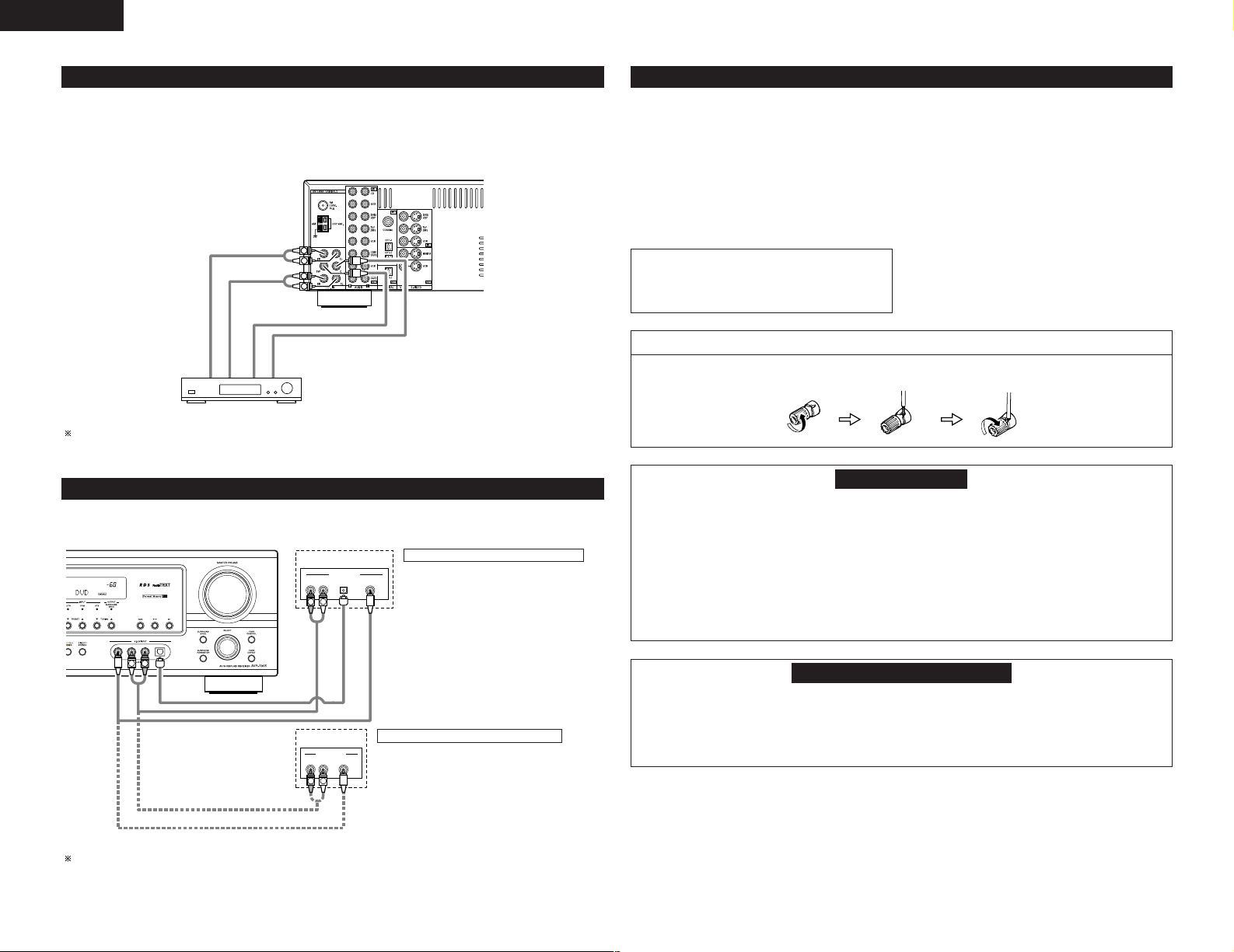
Connecting the external input (EXT. IN) jacks
• These jacks are for inputting multi-channel audio signals from an outboard decoder, or a component with a
different type of multi-channel decoder, such as a DVD Audio player, a multi-channel SACD player, or other
future multi-channel sound format decoder.
• When making connections, also refer to the operating instructions of the other components.
Decoder with 6-channel
analog output
Front
Surround
Subwoofer
Center
For instructions on playback using the external input (EXT. IN) jacks. (See page 21)
Connecting the video component equipped with V. AUX jacks
To connect the video signal, connect using a 75 Ω/ohms video signal cable cord.
Video game
Connecting a Video game component
• Connect the Video game component’s output
jacks to this unit’s V. AUX INPUT jacks.
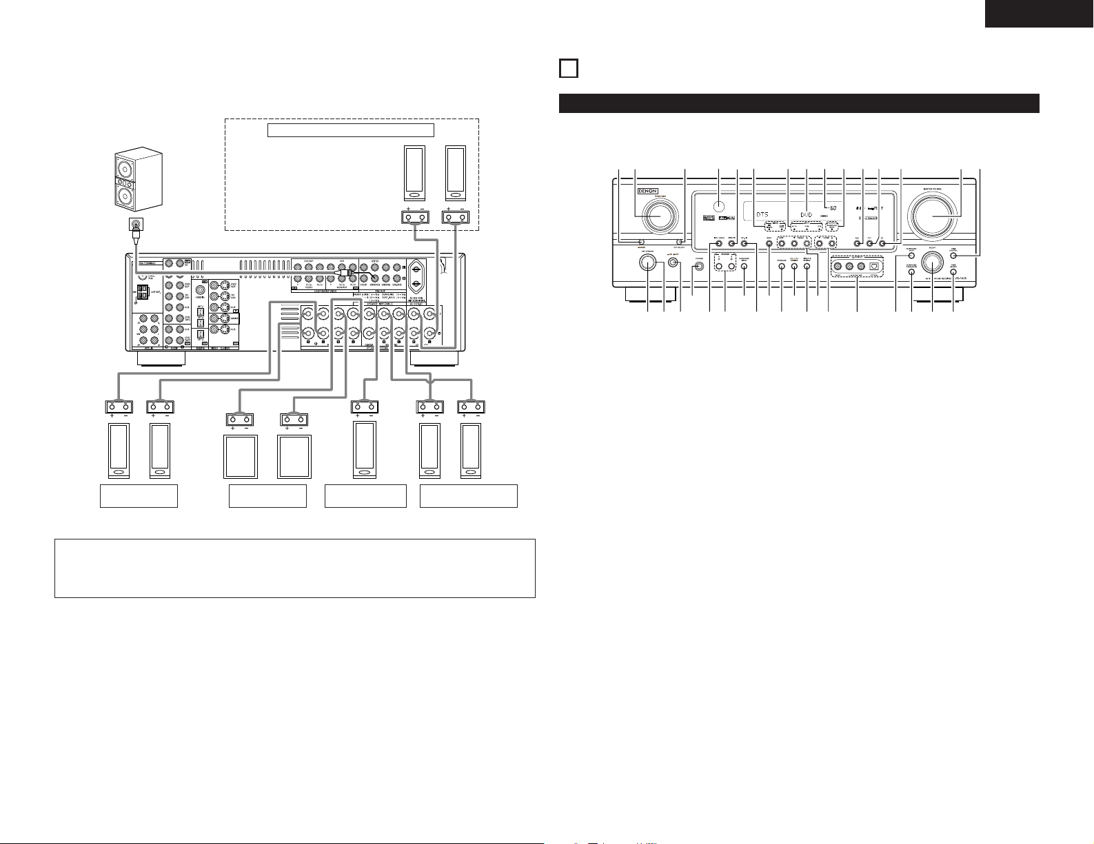
Speaker system connections
• Connect the speaker terminals with the speakers
making sure that like polarities are matched (< with
<, > with >). Mismatching of polarities will result
in weak central sound, unclear orientation of the
various instruments, and the sense of direction of
the stereo being impaired.
• When making connections, take care that none of
the individual conductors of the speaker cord come
in contact with adjacent terminals, with other
speaker cord conductors, or with the rear panel.
NOTE:
NEVER touch the speaker terminals when the
power is on.
Doing so could result in electric shocks.
Connecting the speaker cords
1. Loosen by turning
counterclockwise.
2. Insert the cord. 3. Tighten by turning
Speaker Impedance
• When speaker systems A and B are use separately,
speakers with an impedance of 6 to 16 Ω/ohms can
be connected for use as front speakers.
• Be careful when using two pairs of front speakers
(A + B) at the same time, since use of speakers with
an impedance of 12 to 16 Ω/ohms.
• Speakers with an impedance of 6 to 16 Ω/ohms can
be connected for use as center and surround and
surround back speakers.
• The protector circuit may be activated if the set is
played for long periods of time at high volumes
when speakers with an impedance lower than the
specified impedance are connected.
clockwise.
Protector circuit
• This unit is equipped with a high-speed protection circuit. The purpose of this circuit is to protect the
speakers under circumstances such as when the output of the power amplifier is inadvertently shortcircuited and a large current flows, when the temperature surrounding the unit becomes unusually high, or
when the unit is used at high output over a long period which results in an extreme temperature rise.
When the protection circuit is activated, the speaker output is cut off and the power supply indicator LED
flashes. Should this occur, please follow these steps: be sure to switch off the power of this unit, check
whether there are any faults with the wiring of the speaker cables or input cables, and wait for the unit to
cool down if it is very hot. Improve the ventilation condition around the unit and switch the power back on.
If the protection circuit is activated again even though there are no problems with the wiring or the
ventilation around the unit, switch off the power and contact a DENON service center.
Video camera
The V. AUX INPUT terminal is covered with a cap. Remove this cap in order to use the terminal. (See page 3
for instructions on removing the cap.)
8
Connecting a video camera component
• Connect the video camera component’s output
jacks to this unit’s V. AUX INPUT jacks.
Note on speaker impedance
• The protector circuit may be activated if the set is played for long periods of time at high volumes when
speakers with an impedance lower than the specified impedance (for example speakers with an
impedance of lower than 4 Ω/ohms) are connected. If the protector circuit is activated, the speaker output
is cut off. Turn off the set’s power, wait for the set to cool down, improve the ventilation around the set,
then turn the power back on.
Page 9
ENGLISH
(R) (L)
(L) (R) (L) (R)
(L) (
R
)
qwuei
r
y
o
!4
t
!1
@1@2@3@4@5@6@7@8
@9
!2
!3
!5 !6 !7!0!8@0!9
#0#1#3
#4 #2
Connections
• When making connections, also refer to the operating instructions of the other components.
Connection jack for subwoofer with
built-in amplifier (subwoofer), etc.
FRONT SPEAKER
SYSTEMS (B)
• Precautions when connecting speakers
If a speaker is placed near a TV or video monitor, the colors on the screen may be disturbed by the
speaker’s magnetism. If this should happen, move the speaker away to a position where it does not have
this effect.
SURROUND BACK SPEAKER SYSTEMS
NOTE:
• To use Surround back with one speaker,
connect the speaker to SURR. BACK L
CH.
FRONT SPEAKER
SYSTEMS (A)
CENTER SPEAKER
SYSTEM
SURROUND SPEAKER
SYSTEMS
6
PART NAMES AND FUNCTIONS
Front Panel
• For details on the functions of these parts, refer to the pages given in parentheses ( ).
Power ON/STANDBY switch .............(12, 19, 31)
q
POWER indicator .....................................(12, 19)
w
Power switch ...........................................(12, 19)
e
Headphones jack (PHONES) ..........................(22)
r
INPUT MODE button ...............................(20, 21)
t
SPEAKER A/B buttons .............................(19, 35)
y
SURROUND BACK button .............................(26)
u
EXT. IN button..........................................(20, 21)
i
BAND button..................................................(31)
o
STANDARD button ................................(23 ~ 26)
!0
5CH/7CH STEREO button ..............................(29)
!1
DIRECT/STEREO button.................................(21)
!2
Preset station select buttons .........................(32)
!3
TUNING • (up) / ª (down) buttons ................(31)
!4
V. AUX INPUT jacks......................................(3, 8)
!5
SURROUND MODE button............................(20)
!6
SURROUND PARAMETER button...........(24, 29)
!7
SELECT knob .....................................(20, 25, 29)
!8
TONE DEFEAT button....................................(22)
!9
TONE CONTROL button ................................(22)
@0
MASTER VOLUME control ............................(20)
@1
RT button........................................................(35)
@2
PTY button......................................................(34)
@3
RDS button...............................................(33, 34)
@4
OUTPUT indicator...........................................(26)
@5
MASTER VOLUME indicator..........................(20)
@6
Display
@7
INPUT mode indicator ....................................(20)
@8
SIGNAL indicator............................................(20)
@9
ANALOG button .......................................(20, 21)
#0
Remote control sensor...................................(10)
#1
REC SELECT button.......................................(23)
#2
FUNCTION knob ......................................(20, 23)
#3
SOURCE selector button ...............................(20)
#4
9
Page 10
ENGLISH
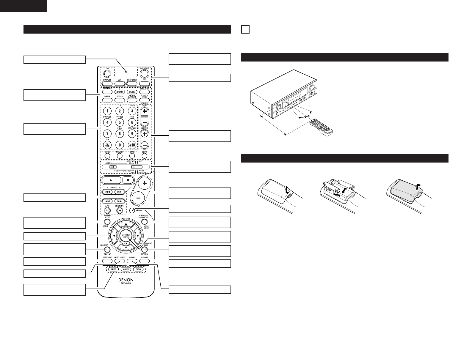
Remote control unit
• For details on the functions of these parts, refer to the pages given in parentheses ( ).
LED (indicator) .......................(17, 19)
SURROUND
buttons.............................(20, 23, 29)
Input source selector buttons
...............................................(17~20)
System buttons .....................(17, 18)
Remote control signal
transmitter ...................................(10)
Power buttons.................(12, 17~19)
Tuner system/System
buttons.............................(17, 18, 31)
Mode select
switches ................................(17~19)
Master volume control
buttons.........................................(20)
7
USING THE REMOTE CONTROL UNIT
Following the procedure outlined below, insert the batteries before using the remote control unit.
Range of operation of the remote control unit
Point the remote control unit at the remote control
sensor as shown on the diagram at the left.
NOTES:
• The remote control unit can be used from a straight
distance of approximately 7 meters, but this
distance will shorten or operation will become
difficult if there are obstacles between the remote
control unit and the remote control sensor, if the
30°
30°
Approx. 7 m
remote control sensor is exposed to direct sunlight
or other strong light, or if operated from an angle.
• Neon signs or other devices emitting pulse-type
noise nearby may result in malfunction, so keep the
set as far away from such devices as possible.
Inserting the batteries
q Press as shown by the arrow
and slide off.
w Insert the R6P/AA batteries properly,
as shown on the diagram.
e Close the lid.
SYSTEM SETUP/
SETUP button ........................(11, 18)
Cursor buttons.................(11, 18, 25)
ON SCREEN/
DISPLAY button.....................(18, 27)
TEST TONE button ......................(23)
VIDEO SELECT button.................(22)
INPUT MODE selector
buttons...................................(20, 21)
10
MUTING button ...........................(22)
SURROUND PARAMETER
button.....................................(18, 24)
CH SELECT (channel select)/
ENTER button............(11, 18, 24, 25)
SURROUND BACK/
RETURN button .....................(18, 26)
SPEAKER button..........................(19)
DIMMER button...........................(22)
NOTES:
• Use only R6P/AA batteries for replacement.
• Be sure the polarities are correct. (See the illustration inside the battery compartment.)
• Remove the batteries if the remote control transmitter will not be used for an extended period of time.
• If batteries leak, dispose of them immediately. Avoid touching the leaked material or letting it come in contact
with clothing, etc. Clean the battery compartment thoroughly before installing new batteries.
• Have replacement batteries on hand so that the old batteries can be replaced as quickly as possible when the
time comes.
• Even if less than a year has passed, replace the batteries with new ones if the set does not operate even when
the remote control unit is operated nearby the set. (The included battery is only for verifying operation. Replace
it with a new battery as soon as possible.)
Page 11
ENGLISH
8
SETTING UP THE SYSTEM
• Once all connections with other AV components have been completed as described in “CONNECTIONS” (see
pages 5 to 9), make the various settings described below on the monitor screen using the AVR-1905’s on-
screen display function.
These settings are required to set up the listening room’s AV system centered around the AVR-1905.
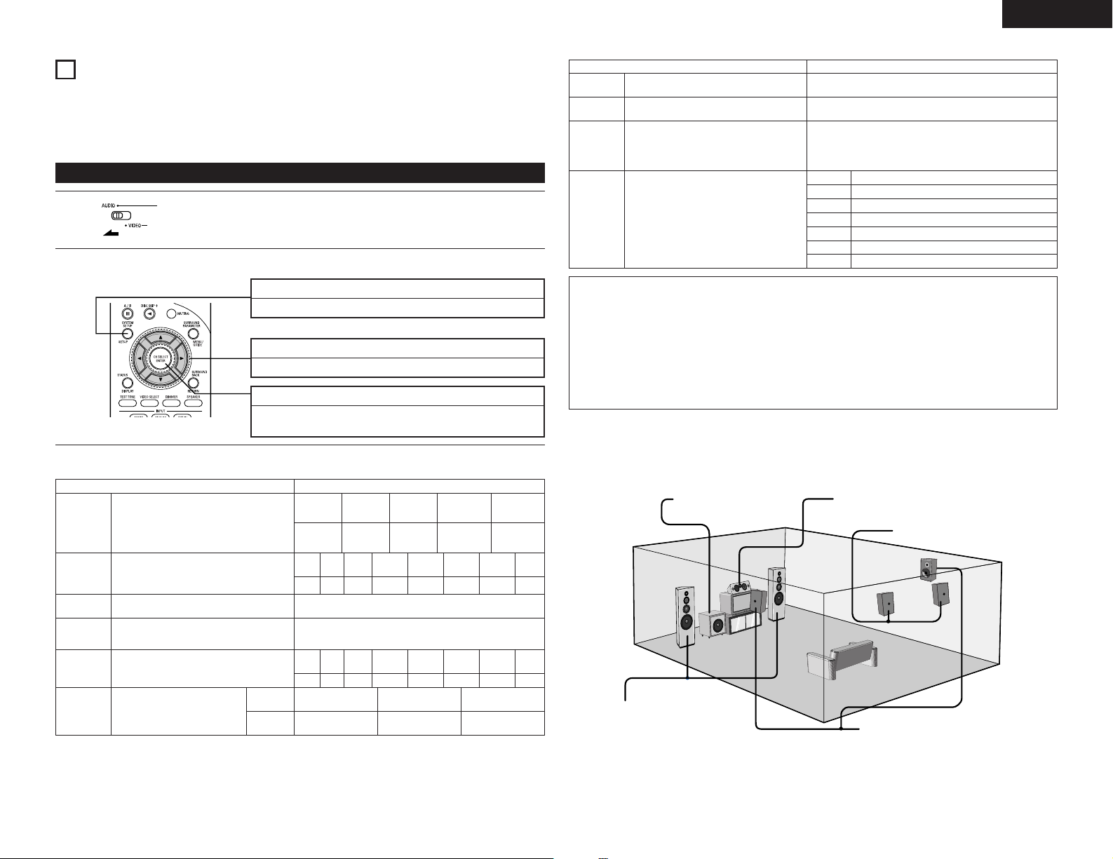
Use the following buttons to set up the system
1
Use the following buttons to set up the system:
2
• System setup items and default values (set upon shipment from the factory)
Input the combination of speakers in your system
Speaker
Configuration
Delay Time
Subwoofer
mode
Crossover
Frequency
Test Tone
Digital In
Assignment
and their corresponding sizes (SMALL for regular
speakers, LARGE for full-size, full-range) to
automatically set the composition of the signals
output from the speakers and the frequency
response.
This parameter is for optimizing the timing with
which the audio signals are produced from the
speakers and subwoofer according to the listening
position.
This selects the subwoofer speaker for playing deep
bass signals.
Set the frequency (Hz) below which the bass sound
of the various speakers is to be output from the
subwoofer.
This adjusts the volume of the signals output from
the speakers and subwoofer for the different
channels in order to obtain optimum effects.
This assigns the digital input jacks for
the different input sources.
Set the slide switch to “AUDIO”.
SYSTEM SETUP button
Press this to display the system setup on the display.
CURSOR buttons (•, ª, 0, 1)
Press this change what appears on the display.
ENTER button
Press this to switch the display.
Also use this button to complete the setting.
System setup Default settings
Input
source
Digital
Inputs
Front Sp.
Large
Front
L
3.6 m
Front
L
0 dB 0 dB
Center
Front
Center
R
3.6 m
3.6 m
Front
Center
R
0 dB
CD DVD/VDP
COAXIAL OPTICAL 1
Surround
Sp.
Small Small
Subwoofer mode = LFE (Normal)
Surround
L
3.0 m
Surround
L
0 dB
Sp.
Surround
R
3.0 m
80 Hz
Surround
R
0 dB
Surround
Back Sp.
Small /
2 spkrs
Surround
Back L
3.0 m
Surround
Back L
0 dB
Subwoofer
Ye s
Surround
Back R
3.0 m
Surround
Back R
0 dB
TV/DBS
OPTICAL 2
Sub-
woofer
3.6 m
Sub-
woofer
0 dB
Auto Surround
Mode
Ext. In SW
Level
On Screen
Display
Auto Tuner
Presets
System setup Default settings
Auto surround mode function setting.
Set the Ext. In Subwoofer channel playback level.
This sets whether or not to display the on-screen
display that appears on the monitor screen when
the controls on the remote control unit or main unit
are operated.
A setting to prevent flickering.
FM stations are received automatically and stored
in the memory.
A1 ~ A8
B1 ~ B8
C1 ~ C8
D1 ~ D8
E1 ~ E8
F1 ~ F8
G1 ~ G8
Auto Surround Mode = ON
Ext. In SW Level = +15 dB
On Screen Display = ON / Mode 1
87.5/89.1/98.1/108.0/90.1/90.1/90.1/90.1 MHz
522/603/999/1404/1611 kHz, 90.1/90.1/90.1 MHz
90.1 MHz
90.1 MHz
90.1 MHz
90.1 MHz
90.1 MHz
NOTES:
• The on-screen display signals are output with priority to the S-VIDEO MONITOR OUT jack during playback
of a video component. For example, if the TV monitor is connected to both the AVR-1905’s S-Video and
video monitor output jacks and signals are input to the AVR-1905 from a video source (VDP, etc.) connected
to both the S-Video and video input jacks, the on-screen display signals are output with priority to the SVideo monitor output. If you wish to output the signals to the video monitor output jack, do not connect a
cord to the S-VIDEO MONITOR OUT jack. (For details, see page 16.)
• The AVR-1905’s on-screen display function is designed for use with high resolution monitor TVs, so it may
be difficult to read small characters on TVs with small screens or low resolutions.
• The setup menu is not displayed when headphone are being used.
2 Speaker system layout
Basic system layout
• The following is an example of the basic layout for a system consisting of eight speaker systems and a
television monitor:
Subwoofer Center speaker system
Surround back speaker system
Front speaker systems
Set these at the sides of the TV or
screen with their front surfaces as flush
Surround speaker systems
with the front of the screen as possible.
11
Page 12
ENGLISH
*SYSTEM SET UP
ON / STANDBY
ON OFF
1 FRONT LARGE
Before setting up the system
Refer to “CONNECTIONS” (pages 5 to 9) and check that all connections are correct.
1
2
(Main unit)
3
(Main unit)
(Remote control unit)
4
(Remote control unit)
5
(Remote control unit)
NOTE:
• Press the SYSTEM SETUP button again to finish system set up. System set up can be finished at any time.
The changes to the settings made up to that point are entered.
Press the Power switch (button).
• ¢ ON
The power turns on and indicator is light.
Set the power switch to this position to turn the power on and off from the
included remote control unit.
•
£ OFF
The power turns off and indicator is off.
In this position, the power cannot be turned on and off from the remote control
unit.
Turn on the power.
Press the Power ON/STANDBY switch (button).
Press the SYSTEM SETUP button to enter the
setting.
NOTE: Please make sure the “AUDIO” position of
the slide switch on the remote control unit.
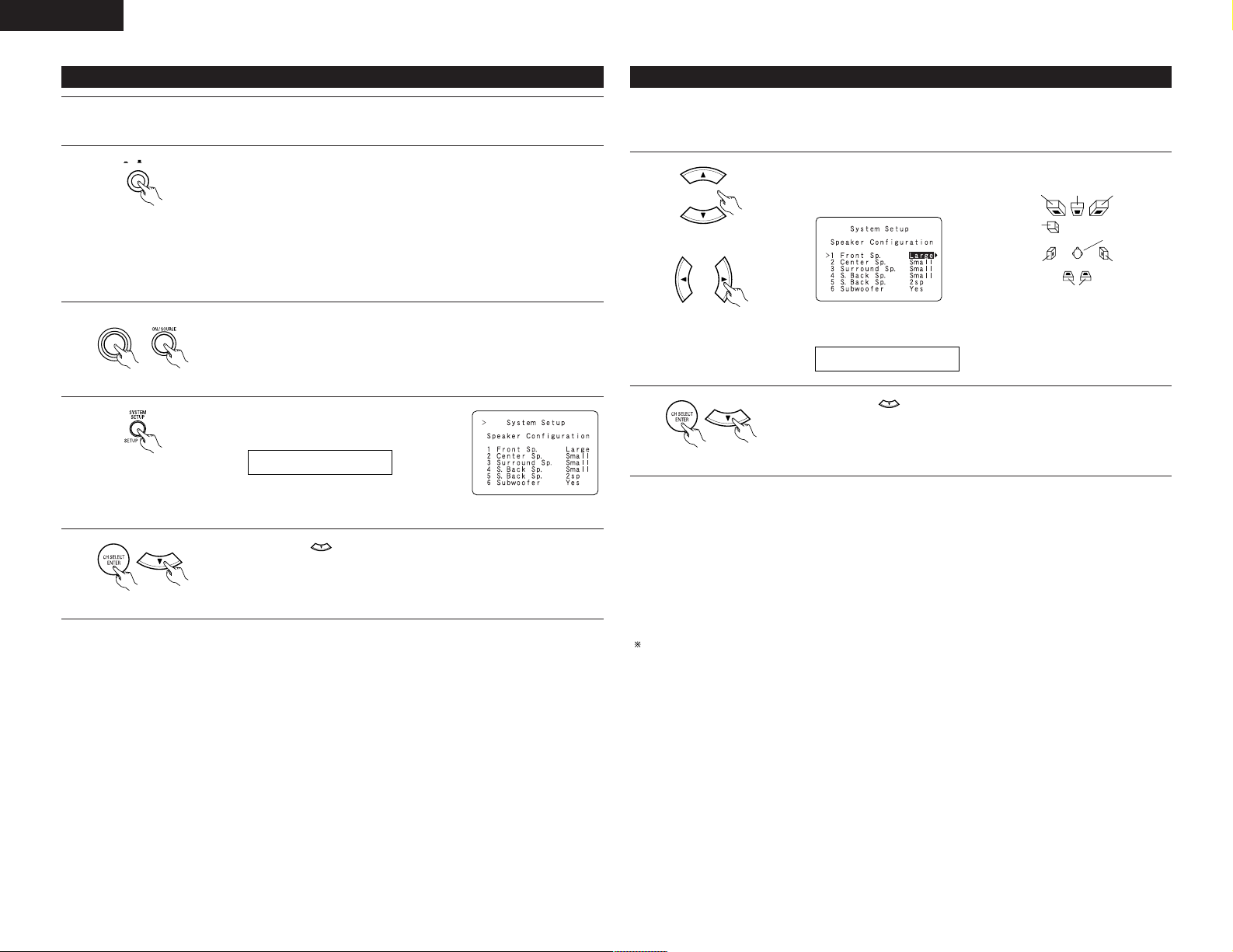
Press the ENTER or (down) button to switch to the Speaker Configuration
Setup.
Setting the type of speakers
• Set up in function of your speaker systems. Performing this setup optimizes the system.
• The composition of the signals output to the different channels and the frequency response are adjusted
automatically according to the combination of speakers actually being used.
1
(Remote control unit)
(Remote control unit)
2
(Remote control unit)
• Parameters
Large.................Select this when using speakers that have sufficient performance for reproducing bass sound
below the frequency set for the Crossover Frequency mode.
Small.................Select this when using speakers that do not have sufficient performance for reproducing bass
sound below the frequency set for the Crossover Frequency mode. When this is set, bass
sound with a frequency below the frequency set for the Crossover Frequency mode is sent
to the subwoofer.
None .................Select this when no speakers are installed.
Yes/No...............Select “Ye s ” when a subwoofer is installed, “No” when a subwoofer is not installed.
2spkrs/1spkr .....Set the number of speakers to be used for the surround back channel.
If the subwoofer has sufficient low frequency playback capacity, good sound can be achieved even when
“Small” is set for the front, center and surround speakers.
Set whether or not speakers are connected and, if so, their size parameters.
• To select the speaker
Subwoofer
Surround Sp.
• To select the parameter
Press the ENTER or (down) button to enter the settings and switch to the
SPEAKER DISTANCE setting.
Center Sp. Front Sp.Front Sp.
Listening position
Surround Sp.
Surround back Sp.
12
Page 13
ENGLISH
15SW MODE NORM
16CR.OVER 80Hz
L1
L2
L5
L3
L4
7 FRONT L 3.6m
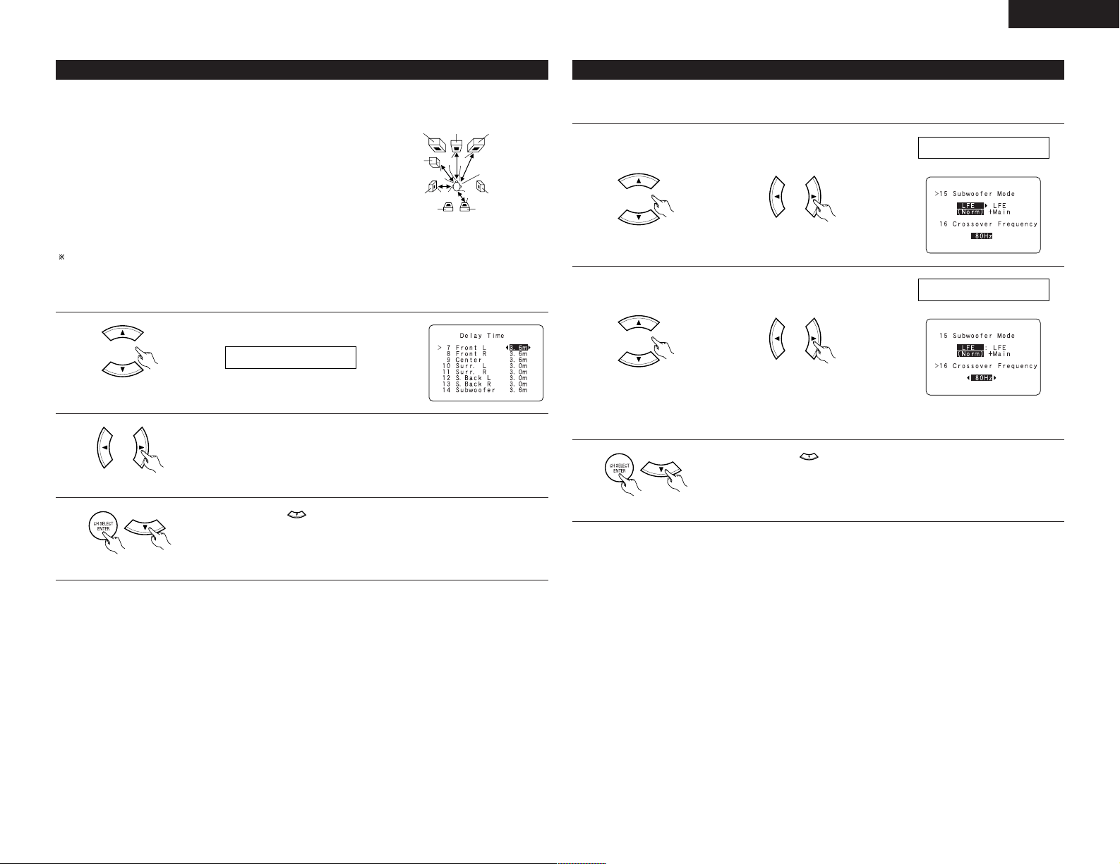
Setting the delay time
• Input the distance between the listening position and the different speakers to set the delay time for the surround
mode.
Preparations:
Measure the distances between the listening position and the speakers
(L1 to L5) on the diagram at the right).
L1: Distance between center speaker and listening position
L2: Distance between front speakers and listening position
L3: Distance between surround speakers and listening position
L4: Distance between surround back speaker and listening position
L5: Distance between subwoofer and listening position
CAUTION:
Please note that the difference for every speaker should be 6.0 m or less.
NOTE:
• No setting when “None” has been selected for the Speaker Configuration setting.
1
(Remote control unit)
2
(Remote control unit)
Select the speaker to be set.
Set the distance between the speaker and listening position.
The distance changes in units of 0.1 meters each time the button is pressed.
Select the value closest to the measured distance.
Subwoofer
Center FRFL
Listening position
SL
SBL
SR
SBR
Setting the Subwoofer mode and Crossover Frequency
This screen is not displayed when not using a subwoofer.
• Set the crossover frequency and subwoofer mode according to the speaker system being used.
Select the “Subwoofer
1
Mode”.
(Remote control unit) (Remote control unit)
Select the “Crossover
2
Frequency” mode.
(Remote control unit) (Remote control unit)
3
Press the ENTER or (down) button to enter the setting and switch to the
Test Tone setting.
Select the setting.
Select the frequency.
• 40 / 60 / 80 / 100 / 120 /
150 / 200 / 250 Hz can be
selected.
3
(Remote control unit)
Press the ENTER or (down) button to enter the setting and switch the
SUBWOOFER MODE setting.
(Remote control unit)
13
Page 14
ENGLISH
17 T.TONE <YES
T.TONE AUTO
FL C FR SR SBR SBL SL SW
SB
NOTES:
— Assignment of low frequency signal range —
• The signals produced from the subwoofer channel are LFE signals (during playback of Dolby Digital or DTS
signals) and the low frequency signal range of channels set to “SMALL” in the setup. The low frequency
signal range of channels set to “LARGE” are produced from those channels.
— Crossover Frequency —
• When “Subwoofer” is set to “Ye s ” at the “Speaker Configuration Setting”, set the frequency (Hz) below
which the bass sound of the various speakers is to be output from the subwoofer (the crossover
frequency).
• For speakers set to “Small”, sound with a frequency below the crossover frequency is cut, and the cut bass
sound is output from the subwoofer instead.
NOTE: For ordinary speaker systems, we recommend setting the crossover frequency to 80 Hz. When
using small speakers, however, setting the crossover frequency to a high frequency may improve
frequency response for frequencies near the crossover frequency.
— Subwoofer mode —
• The subwoofer mode setting is only valid when “Large” is set for the front speakers and “YES” is set for
the subwoofer in the “Speaker Configuration” settings (see page 12).
• When the “LFE+MAIN” playback mode is selected, the low frequency signal range of channels set to
“Large” are produced simultaneously from those channels and the subwoofer channel.
In this playback mode, the low frequency range expand more uniformly through the room, but depending
on the size and shape of the room, interference may result in a decrease of the actual volume of the low
frequency range.
• Selection of the “LFE ” play mode will play the low frequency signal range of the channel selected with
“Large” from that channel only. Therefore, the low frequency signal range that are played from the
subwoofer channel are only the low frequency signal range of LFE (only during Dolby Digital or DTS signal
playback) and the channel specified as “Small” in the setup menu.
• Select the play mode that provides bass reproduction with quantity.
• When the subwoofer is set to “Ye s”, bass sound is output from the subwoofer regardless of the subwoofer
mode setting in surround modes other than Dolby/DTS.
• In surround modes other than Dolby Digital and DTS, if the subwoofer is set to “YES”, the low frequency
portion is always output to the subwoofer channel. For details, refer to “Surround Modes and Parameters”
on page 30.
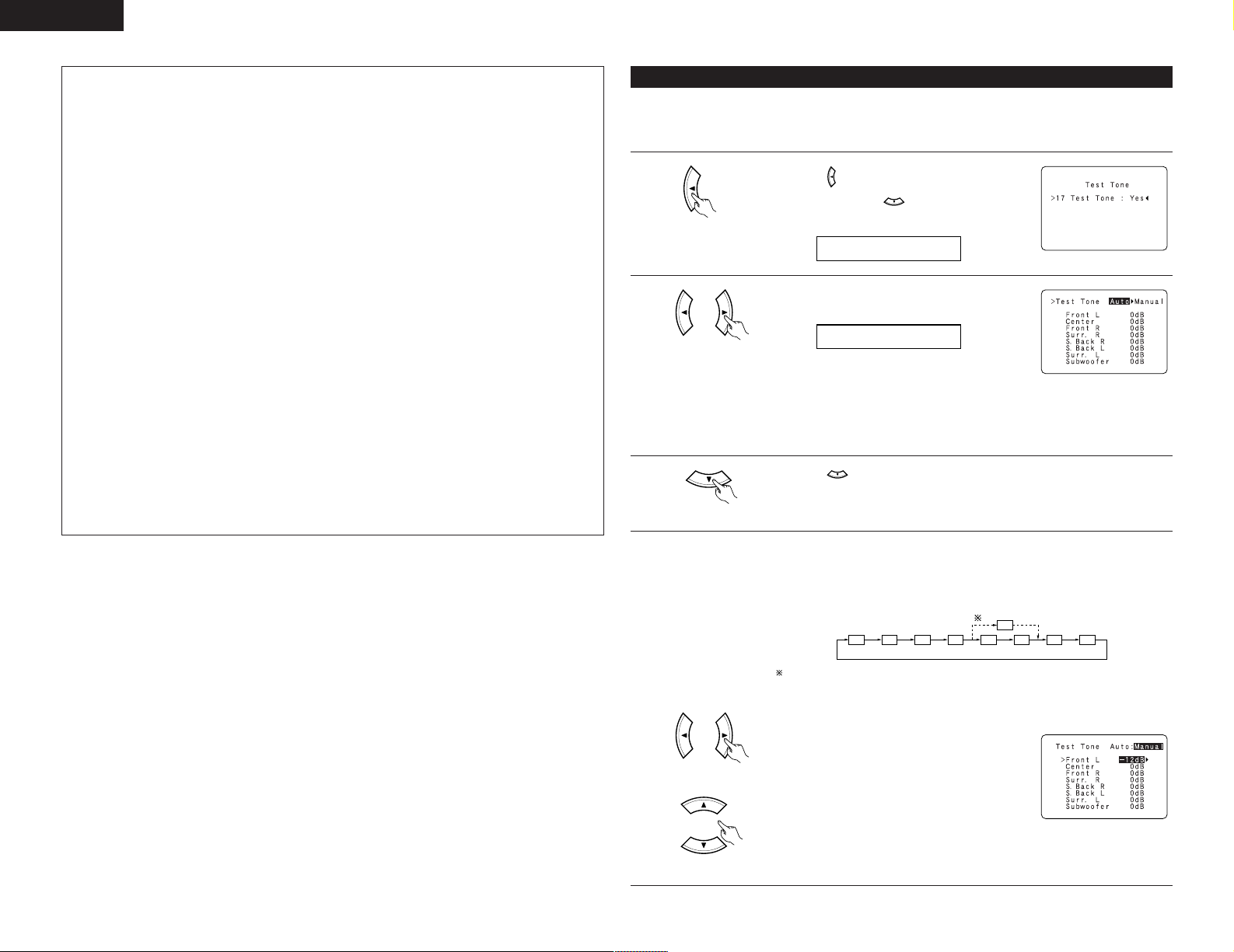
Setting the Test Tone
• Use this setting to adjust to that the playback level between the different channel is equal.
• From the listening position, listen to the test tones produced from the speakers to adjust the level.
• The level can also be adjusted directly from the remote control unit. (For details, see page 23.)
1
(Remote control unit)
2
(Remote control unit)
3
(Remote control unit)
4
• Use the (left) button to the Test Tone.
• Press the ENTER or (down) button to switch
to the Digital In Assignment.
Set the mode.
Select “Auto” or “Manual”.
• Auto:
Adjust the level while listening to the test tones
produced automatically from the different speakers.
• Manual:
Select the speaker from which you want to produce the test tone to adjust the
level.
Press the (down) button to start Test Tone.
a. If the “Auto” mode is selected:
Test tones are automatically emitted from the different speakers.
The test tones are emitted from the different speakers in the following order, at
4-second intervals the first time and second time around, 2-second intervals the
third time around and on:
1spkr
14
(Remote control unit)
(Remote control unit)
2spkrs
When the surround back speaker setting is set to “1sp” for “Speaker
Configuration”, this is set to “SB”.
Use the CURSOR left and right buttons to adjust all the speakers to the same
volume.
The volume can be adjusted between –12 dB and
+12 dB in units of 1 dB.
b. When the “Manual” mode is selected
Use the CURSOR up and down to select the
speaker for which you want to output test tones,
then use the CURSOR left and right to adjust so
that the volume of the test tones from the various
speakers is the same.
Example:
When the volume is set to –12
dB while the Front Lch speaker is
selected
Page 15
ENGLISH
18 COAX CD
21 AUTOSURR. ON
5
(Remote control unit)
6
(Remote control unit)
NOTES:
• When you adjust the channel levels while in the TEST TONE mode, the channel level adjustments made
will affect all surround modes. Consider this mode a Master Channel Level adjustment mode.
• You can adjust the channel levels for each of the following surround modes: DIRECT, STEREO, STANDARD
(DOLBY/DTS SURROUND), 5/7 CH STEREO, MONO MOVIE, ROCK ARENA, JAZZ CLUB, VIDEO GAME,
MATRIX and VIRTUAL.
After completing the adjustment, press the ENTER button.
Press the ENTER or (down) button to enter the setting and switch the
DIGITAL input setting.
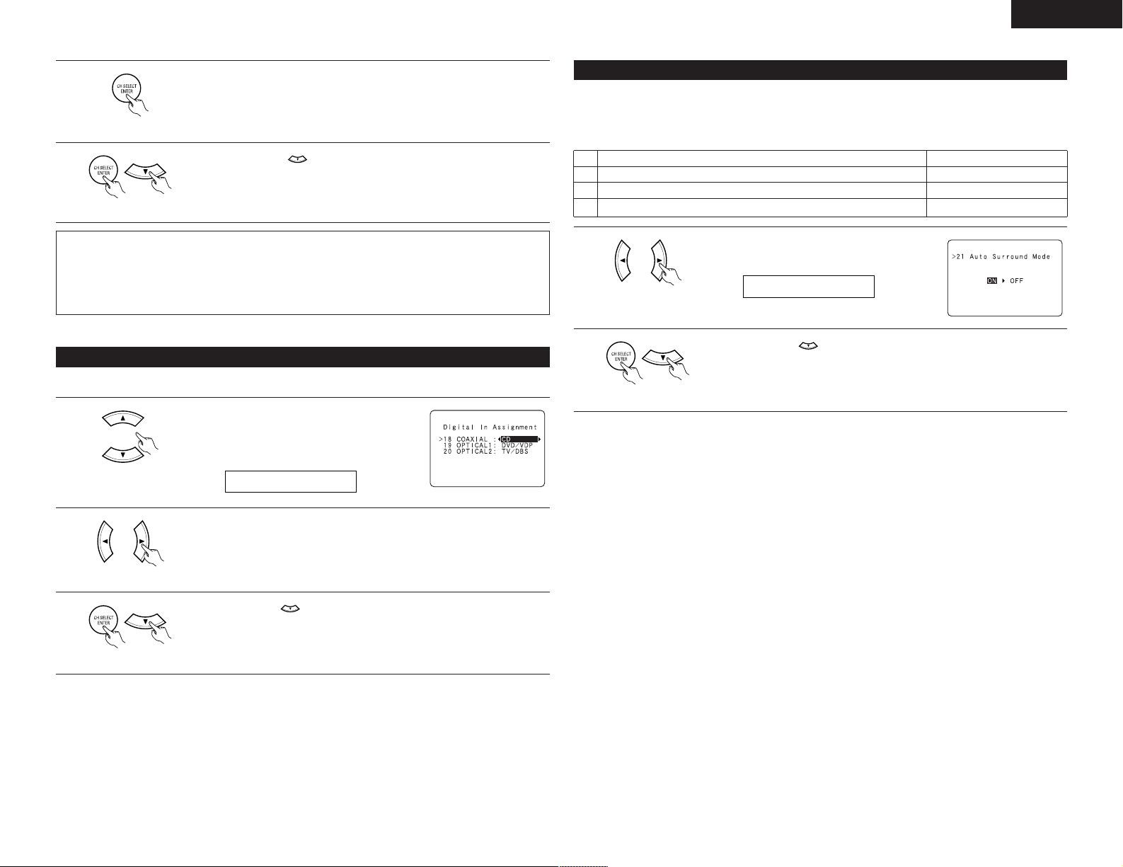
Setting the Digital In Assignment
• This setting assigns the digital input jacks of the AVR-1905 for the different input sources.
1
(Remote control unit)
Select the digital input jack to be assigned to the
input source.
• To select the digital input jack
Setting the Auto Surround Mode
For the three kinds of input signals as shown below, the surround mode played the last is stored in the memory.
At next time it the same signal inputs, the memorized surround mode is automatically selected and the signal
is played.
Note that the surround mode setting is also stored separately for the different input function.
SIGNAL Default Auto Surround Mode
q Analog and PCM 2-channel signals STEREO
w 2-channel signals of Dolby Digital, DTS or other multichannel format Dolby PL
e Multichannel signals of Dolby Digital, DTS or other multichannel format Dolby or DTS Surround
1
(Remote control unit)
2
(Remote control unit)
Select “ON” if you want to use the auto surround
mode, “OFF” if you do not want to use it.
Press the ENTER or (down) button to switch the Ext. In SW Level setting.
IIx Cinema
2
(Remote control unit)
3
(Remote control unit)
NOTE:
• TUNER and V. AUX cannot be selected.
• To select the input source
Select “OFF” if nothing is connected.
Press the ENTER or (down) button to enter the setting and switch the Auto
Surround Mode setting.
15
Page 16

ENGLISH
22 EXT.IN SW+15
23 OSD ON
25 PRESET <YES
24 OSD MODE1
Setting the Ext. In SW Level
• Set the playback level of the analog input signal connected to the Ext. In terminal.
1
(Remote control unit)
2
(Remote control unit)
Select desired setting.
• Select according to the specifications of the player
being used.
Also refer to the player’s operating instructions.
• +15dB (default) recommended. (0, +5, 10 and +15
can be selected.)
Press the ENTER or (down) button to switch the On Screen Display setting.
Setting the On Screen Display (OSD)
• Use this to turn the on-screen display (messages other than the menu screens) on or off.
• Sets the on-screen display’s display mode.
Mode 1: Prevents flickering of the on-screen display when there is no video signal.
Mode 2: Flickering is not prevented.
Use this mode if the on-screen display does not appear in the mode 1, as may happen according
to the TV being used.
Auto Tuner Presets
• Use this to automatically search for FM broadcasts and store up to 56 stations at preset channels A1 to 8, B1
to 8, C1 to 8, D1 to 8, E1 to 8, F1 to 8 and G1 to 8.
NOTE:
• If an FM station cannot be preset automatically due to poor reception, use the “Manual tuning” operation to
tune in the station, then preset it using the manual “Preset memory” operation.
1
(Remote control unit)
2
(Remote control unit)
Use the CURSOR button to select “Ye s”.
“Search” flashes on the screen and searching begins.
“Completed” appears once searching is completed.
The display automatically switches to screen.
Press the ENTER or (down) button if you want to start the settings over from
the beginning.
After setting up the system
1
Press the SYSTEM SETUP button to finish system set up.
1
(Remote control unit)
Select the “On Screen
2
Display” mode.
(Remote control unit) (Remote control unit)
3
(Remote control unit)
16
Select “ON” or “OFF”.
Select the “MODE1” or
“MODE2”.
Press the ENTER or (down) button to switch the Auto Preset Memory
setting.
(Remote control unit)
This completes the system setup operations. Once the system is set up, there is no need to make the
settings again unless other components or speakers are connected to or the speaker layout is changed.
• On-screen display signals
Signals input to the AVR-1905
VIDEO signal input jack
(yellow)
1
2
3
4
(C: Signal E: No signal) (C: On-screen signals output E: On-screen signals not output)
E
C
E
C
S-video signal input jack
E
E
C
C
VIDEO MONITOR OUT jack
On-screen display signal output
Video signal output to
(yellow)
C
C
C
E
Video signal output to S-
Video MONITOR OUT jack
C
C
C
C
Page 17

ENGLISH
1
2
3
456
789
0
3
2
1
4
9
REMOTE CONTROL UNIT
Operating DENON audio components
• Turn on the power of the different components before operating them.
Set mode switch 1 to “AUDIO”.
1
Set mode switch 2 to the position for the
2
component to be operated. (CD, CDR/MD or
Tape deck)
Operate the audio component.
3
• For details, refer to the component’s operating instructions.
While this remote control is compatible with a wide range of infrared controlled components, some
models of components may not be operated with this remote control.
1. CD player (CD) and CD recorder and MD
recorder (CDR/MD) system buttons
2. Tape deck (TAPE) system buttons
1
3
Preset memory
DENON and other makes of components can be operated by setting the preset memory.
This remote control unit can be used to operate components of other manufacturers without using the learning
function by registering the manufacturer of the component as shown on the List of Preset Codes (pages
276~278).
Operation is not possible for some models.
Set mode switch 1 to “AUDIO” or “VIDEO”.
1
3
Set the AUDIO side for the CD, Tape deck or
2
CDR/MD position, to the VIDEO side for the
DVD/VDP, DBS/CABLE, VCR or TV position.
Set mode switch 2 to the component to be
2
registered.
Press the ON/SOURCE button and the OFF
3
button at the same time.
• Indicator flash.
NOTE:
• TUNER can be operated when the switch is at “AUDIO” position.
6, 7 : Manual search
2 : Stop
1 : Play
8, 9 : Auto search (cue)
3 : Pause
DISC SKIP + : Switch discs
3. Tuner system buttons
(forward and reverse)
(for CD changers only)
6 : Rewind
7 : Fast-forward
2 : Stop
1 : Forward play
0 : Reverse play
A/B : Switch between decks A and B
SHIFT : Switch preset channel range
CHANNEL +, – : Preset channel up/down
TUNING +, – : Frequency up/down
BAND : Switch between the AM and FM
bands
MODE : Switch between auto and mono
MEMORY : Preset memory
4
To store the codes of another component in the memory, repeat steps 1 to 4.
5
NOTES:
• The signals for the pressed buttons are emitted while setting the preset memory. To avoid accidental
operation, cover the remote control unit’s transmitting window while setting the preset memory.
• Depending on the model and year of manufacture, this function cannot be used for some models, even if
they are of makes listed on the included list of preset codes.
• Some manufacturers use more than one type of remote control code. Refer to the included list of preset
codes to change the number and check.
• The preset memory can be set for one component only among the following: CDR/MD, DVD/VDP
and DBS/CABLE.
The preset codes are as follows upon shipment from the factory and after resetting:
TV, VCR......................................................................HITACHI
CD, TAPE...................................................................DENON
CDR/MD ....................................................................DENON (CDR)
DVD/VDP ...................................................................DENON (DVD)
DBS/CABLE...............................................................ABC (CABLE)
Referring to the included List of Preset Codes, use the number buttons to input the
preset code (a 3-digit number) for the manufacturer of the component whose
signals you want to store in the memory.
17
Page 18

ENGLISH
3
2
1
3
3
Operating component stored in the preset memory
Set mode switch 1 to “AUDIO” or “VIDEO”.
1
Set the AUDIO side for the CD, tape deck or
CDR/MD position, to the VIDEO side for the
DVD/VDP, DBS/CABLE, VCR or TV position.
Set mode switch 2 to the component you want
2
to operate.
Operate the component.
3
• For details, refer to the component’s operating
instructions.
Some models cannot be operated with this
remote control unit.
1. Digital video disc player (DVD) system buttons
POWER : Power on/standby
(ON/SOURCE)
OFF : DENON DVD Power
6, 7 : Manual search
8, 9 : Auto search
0 ~ 9, +10 : 10 key
DISC SKIP : Disc skip
DISPLAY : Switch display
MENU : Menu
RETURN : Return
SETUP : Setup
•, ª,
ENTER : Enter setting
off
(forward and reverse)
2 : Stop
1 :Play
(to beginning of track)
3 : Pause
+ (for DVD changer only)
0, 1 : Cursor up, down, left
and right
2. Video disc player (VDP) system buttons
POWER : Power on/standby
(ON/SOURCE)
6, 7 : Manual search
2 : Stop
1 :Play
8, 9 : Auto search (cue)
3 : Pause
0~9, +10 : 10 key
(forward and reverse)
3. Video deck (VCR) system buttons
POWER : Power on/standby
(ON/SOURCE)
6, 7 : Manual search
Channel : Channels
+, –
5. Monitor TV (TV) system buttons
POWER : Power on/standby
(ON/SOURCE)
MENU : Menu
RETURN : Return
•, ª,
ENTER : Enter
CHANNEL : Switch channels
+, –
0~9, +10 : Channels
DISPLAY : Switch display
TV/VCR : Switch between TV
TV VOL : Volume up/down
+, –
(forward and reverse)
2 : Stop
1 :Play
3 : Pause
0, 1 : Cursor up, down, left
and right
and video player
4. Digital broadcast satellite (DBS) tuner and
cable (CABLE) system buttons
POWER : Power on/standby
(ON/SOURCE)
MENU : Menu
RETURN : Return
•, ª,
0, 1 : Cursor up, down, left
ENTER : Enter
CHANNEL : Switch channels
+, –
0~9, +10 : Channels
DISPLAY : Switch display
VOL +, – : Volume up/down
and right
NOTE:
• Some manufacturers use different names for
the DVD remote control buttons, so also refer to
the instructions on remote control for that
component.
18
NOTES:
• For this CD, CDR, MD and TAPE components, buttons can be operated in the same way as for Denon audio
components (page 17).
• The TV can be operated when the switch is at DVD/VDP, VCR, TV position.
Page 19

ENGLISH
1
2
3
456
789
0
3
2
1
4
3
2 1
3
2
3
ON OFF
Punch Through
•“Punch Through” is a function allowing you to operate the PLAY, STOP, MANUAL SEARCH and AUTO SEARCH
buttons on the CD, TAPE, CDR/MD, DVD/VDP or VCR components when in the DBS/CABLE or TV mode. By
default, nothing is set.
Set mode switch 1 to “VIDEO”.
1
Set mode switch 2 to the component to be
2
registered (DBS/CABLE or TV).
Press the DVD/VDP POWER button and the TV
3
POWER button at the same time.
• Indicator flash.
Input the number of the
component you want to
set. (See Table 1)
No.
1
2
3
4
5
0
4
Table 1
CD
TAPE
CDR/MD
DVD/VDP
VCR
No setting
10
OPERATION
Before operating
Preparations:
Check that all connections are proper.
Press the power switch (button).
1
(Main unit)
• ¢ ON
The power turns on and indicator is light.
Set the power switch to this position to turn
the power on and off from the included
remote control unit.
•
£ OFF
The power turns off and power indicator is
off.
In this position, the power cannot be turned
on and off from the remote control unit.
Turn on the power.
2
Press the Power ON/STANDBY switch (button).
(Main unit)
When pressed, the power turns on and the
display lights. The sound is muted for several
seconds, after which the unit operates normally.
When pressed again, the power turns off, the
standby mode is set and the display turns off.
Select the front speakers.
3
Press the SPEAKER A or B button to turn the
speaker on.
(Remote control unit)
(Main unit) (Remote control unit)
• The front speaker A, B setting can be also be
changed with the SPEAKER button on the
remote control unit.
19
Page 20

ENGLISH
5
1
3
2
3
1
1
2 5
AUTO PCM DTS
FUNCTION
ANALOG
EXT. IN
INPUT MODE
SOURCE
SIGNAL
DIGITAL
DIGITAL
DIGITAL
SIGNAL
SIGNAL
MASTER VOLUME
SURROUND
MODE
SURROUND
MODE
SELECT
ANALOGDIGITAL
DIGITAL
DIGITAL
ANALOG
AUTO
PCM
DTS
INPUT
AUTO
PCM
DTS
INPUT
AUTO
PCM
DTS
INPUT
AUTO
PCM
DTS
INPUT
Playing the input source
1
2
20
Select the input source to be played.
Example: CD
(Main unit) (Remote control unit)
To select the input source when
REC OUT is selected, press the
SOURCE button then operate
the input function selector.
(Main unit)
Select the input mode.
• Selecting the analog mode
Press the ANALOG button to switch to the
analog input.
(Main unit) (Remote control unit)
• Selecting the external input (EXT. IN) mode
Press the EXT. IN to switch the external input.
(Main unit) (Remote control unit)
• Selecting the AUTO, PCM and DTS modes
The mode switches as shown below each
time the INPUT MODE button is pressed.
(Main unit) (Remote control unit)
Input mode selection function
Different input modes can be selected for the different
input sources. The selected input modes for the
separate input sources are stored in the memory.
q AUTO (auto mode)
In this mode, the types of signals being input to the
digital and analog input jacks for the selected input
source are detected and the program in the AVR1905’s surround decoder is selected automatically
upon playback. This mode can be selected for all
input sources other than TUNER.
The presence or absence of digital signals is
detected, the signals input to the digital input jacks
are identified and decoding and playback are
performed automatically in DTS, Dolby Digital or
PCM (2 channel stereo) format. If no digital signal is
being input, the analog input jacks are selected.
Use this mode to play Dolby Digital signals.
w PCM (exclusive PCM signal playback mode)
Decoding and playback are only performed when
PCM signals are being input.
Note that noise may be generated when using this
mode to play signals other than PCM signals.
e DTS (exclusive DTS signal playback mode)
Decoding and playback are only performed when
DTS signals are being input.
r ANALOG (exclusive analog audio signal playback
mode)
The signals input to the analog input jacks are
decoded and played.
t EXT. IN (external decoder input jack selection mode)
The signals being input to the external decoder
input jacks are played without passing through the
surround circuitry.
NOTE:
• Note that noise will be output when CDs or LDs
recorded in DTS format are played in the “PCM”
(exclusive PCM signal playback) or “ANALOG”
(exclusive PCM signal playback) mode. Select the
AUTO or DTS mode when playing signals recorded
in DTS.
Notes on playing a source encoded with DTS
• Noise may be generated at the beginning of
playback and while searching during DTS
playback in the AUTO mode. If so, play in the
DTS mode.
• In some rare cases the noise may be generated
when you preform the operation to stop
playback of a DTS-CD or DTS-LD.
Select the play mode.
3
Press the SURROUND MODE button, then turn
the SELECT knob.
Example: Stereo
(Main unit) (Remote control unit)
To select the surround mode
while adjusting the surround
parameters, tone defeat or tone
control, press the surround mode
button then operate the selector.
Start playback on the selected component.
4
• For operating instructions, refer to the
(Main unit)
component’s manual.
Adjust the volume.
5
The volume level
is displayed on
the master
volume level
display.
(Main unit) (Remote control
unit)
The volume can be adjusted within the range
of –70 to 0 to 18 dB, in steps of 1 dB.
However, when the channel level is set as
described on page 23, if the volume for any
channel is set at +1 dB or greater, the volume
cannot be adjusted up to 18 dB. (In this case
the maximum volume is adjusted to “18 dB
— (Maximum value of channel level)”.)
Input mode when playing DTS sources
• Noise will be output if DTS-compatible CDs or LDs
are played in the “ANALOG” or “PCM” mode.
When playing DTS-compatible sources, be sure to
connect the source component to the digital input
jacks (OPTICAL/COAXIAL) and set the input mode to
“DTS”.
Input mode display
• In the AUTO mode
One of these lights,
depending on the input
signal.
• In the DIGITAL PCM mode
• In the DIGITAL DTS mode
• In the ANALOG mode
Input signal display
• DOLBY DIGITAL
• DTS
• PCM
The indicator lights when digital signals
DIGITAL
are being input properly. If the indicator
DIGITAL
does not light, check whether the digital input
component setup (page 15) and connections are
correct and whether the component’s power is
turned on.
NOTE:
• The indicator will light when playing
DIGITAL
CD-ROMs containing data other than audio
signals, but no sound will be heard.
Page 21

ENGLISH
2 1
INPUT MODE
EXT. IN
ANALOG
DIRECT /
STEREO
DIRECT /
STEREO
1, 2
2
1
Playback using the external input (EXT. IN) jacks
Set the external input (EXT. IN) mode.
1
Press the EXT. IN to switch the external input.
(Main unit) (Remote control unit)
Once this is selected, the input signals
connected to the FL (front left), FR (front right),
C (center), SL (surround left) and SR (surround
right) channels of the EXT. IN jacks are output
directly to the front (left and right), center and
surround (left and right) speaker systems as
well as the pre-out jacks without passing
through the surround circuitry.
In addition, the signal input to the SW (subwoofer)
jack is output to the PRE OUT SUBWOOFER
jack.
Cancelling the external input mode
2
To cancel the external input (EXT. IN) setting,
press the INPUT MODE (AUTO, PCM, DTS) or
ANALOG button to switch to the desired input
mode. (See page 20.)
(Main unit) (Remote control unit)
• When the input mode is set to the external input
(EXT. IN), the play mode (DIRECT, STEREO,
STANDARD (DOLBY/DTS SURROUND), 5CH/7CH
STEREO or DSP SIMULATION) cannot be selected.
NOTES:
• In play modes other than the external input
• The external input mode can be set for any input
• If the subwoofer output level seems to high, set
21
mode, the signals connected to EXT. IN jacks
cannot be played. In addition, signals cannot be
output from channels not connected to the input
jacks.
source. To watch video while listening to sound,
select the input source to which the video signal
is connected, then set this mode.
the “SW ATT.” surround parameter to “ON”.
Playing audio sources (CDs and DVDs)
The AVR-1905 is equipped with two 2-channel playback modes exclusively for music.
Select the mode to suit your tastes.
DIRECT mode
1
Use this mode to achieve good quality 2channel sound while watching images. In this
mode, the audio signals bypass such circuits as
the tone circuit and are transmitted directly,
resulting in good quality sound.
(Main unit) (Remote control unit)
STEREO mode
2
Use this mode to adjust the tone and achieve
the desired sound while watching images.
(Main unit) (Remote control unit)
21
Page 22

ENGLISH
32 1
SELECT
TONE
DEFEAT
TONE
CONTROL
BASS TREBLE
1
PHONES
1
BRIGHT MEDIUM
OFF
DIM
After starting playback
[1] Adjusting the sound quality (tone)
• The tone control function will not work in the direct mode.
The tone switches as follows each time the
1
TONE CONTROL button is pressed.
(Main unit)
With the name of the volume to
2
be adjusted selected, turn the
SELECT knob to adjust the level.
• To increase the bass or treble: Turn the control
clockwise. (The bass or treble sound can be
increased to up to +12 dB in steps of 2 dB.)
• To decrease the bass or treble: Turn the
control counterclockwise. (The bass or treble
sound can be decreased to up to –12 dB in
steps of 2 dB.)
[2] Listening over headphones
Plug the headphones’ plug
1
into the jack.
Connect the headphones to
the PHONES jack.
The pre-out output (including
the speaker output) is
automatically turned off when headphones
are connected.
[3] Turning the sound off temporarily (MUTING)
(Main unit)
If you do not want the bass and treble to be
3
adjusted, turn on the tone defeat mode.
The signals do not pass through
the bass and treble adjustment
circuits, so it provides higher
(Main unit)
NOTE:
To prevent hearing loss, do not raise the volume level
excessively when using headphones.
quality sound.
[4]
Combining the currently playing sound with the desired image
Simulcast playback
1
Use this switch to monitor a video
source other than the audio source.
Press the VIDEO SELECT button
repeatedly until the desired source
appears on the display.
Cancelling simulcast playback.
• Select “SOURCE” using the VIDEO SELECT
button.
• Switch the program source to the component
connected to the video input jacks.
[5] Checking the currently playing program source, etc.
On screen display
1
• Each time an operation is
performed, a description of that
operation appears on the
display connected to the unit’s
VIDEO MONITOR OUT jack.
Also, the unit’s operating status can be
checked during playback by pressing the
remote control unit’s ON SCREEN/DISPLAY
button.
Such information as the position of the input
selector and the surround parameter settings
is output in sequence.
Using the dimmer function
2
• Use this to change the
brightness of the display.
The display brightness changes
in four steps (bright, medium,
dim and off) by pressing the
main unit’s DIMMER button repeatedly.
(Remote
control unit)
(Remote
control unit)
(Remote
control unit)
1
Display
IN=V SOURCE
1
2
1
22
Use this to turn off the audio
output temporarily.
Press the MUTING button.
Cancelling MUTING mode.
• Press the MUTING button again.
• Muting will also be cancelled when MASTER
VOL is adjusted up or down.
(Remote
control unit)
1
Page 23

ENGLISH
VCR V.AUX CDR / TAPE
CD TUNER AUX DVD / VDP TV / DBS
2
REC
RECOUT SOURCE
12, 4 2
REC SELECT
FUNCTION
FUNCTION
1
STANDARD
3
2, 4
3
1
Multi-source recording
Playing one source while recording another (REC OUT mode)
Press the REC SELECT button.
1
(Main unit)
With “RECOUT SOURCE”
2
displayed, turn the FUNCTION
knob to select the source you
wish to record.
Set the recording mode.
3
• For operating instructions, refer to the manual
of the component on which you want to record.
To cancel, turn the function knob
4
and select “SOURCE”.
NOTES:
• Recording sources other than digital inputs
selected in the REC OUT mode are also output to
the multi source audio output jacks.
• Digital signals are not output to the REC
SOURCE or audio output jacks.
• The DIGITAL IN’s signal selected with the
function selector knob are output to the DIGITAL
OUT (OPTICAL) jack.
(Main unit)
(Main unit)
Display
11
SURROUND
Before playing with the surround function
• Before playing with the surround function, be sure to use the test tones to adjust the playback level from the
different speakers. This adjustment can be performed with the system setup (see page 11) or from the remote
control unit, as described below.
• Adjusting with the remote control unit using the test tones is only possible in the “Auto” mode and only
effective in the STANDARD (DOLBY/DTS SURROUND) modes. The adjusted levels for the different modes are
automatically stored in the memory.
Set the STANDARD (DOLBY/DTS SURROUND)
1
modes.
(Main unit) (Remote control unit)
Press the TEST TONE
2
button.
(Remote control unit)
Test tones are output from
3
the different speakers. Use
the channel volume adjust
buttons to adjust so that
the volume of the test
tones is the same for all
the speakers.
NOTE:
• Please make sure the “AUDIO” position of
the slide switch on the remote control unit.
(Remote control unit)
After completing the
4
adjustment, press the
TEST TONE button again.
(Remote control unit)
23
Page 24

ENGLISH
FL C FR SR SBR SBL
SLSW
2
1
2
STANDARD
LOGIC
II
5, 74, 61 2
4
5, 7
1
9
5, 7
2
6
6
SURROUND
PARAMETER
• After adjusting using the test tones, adjust the channel levels either according to the playback sources or to
suit your tastes, as (described) below.
Select the speaker whose
1
level you want to adjust.
(Remote control unit)
The channel switches as shown below each
time the button is pressed.
When the surround back speaker setting
is set to “1sp” for “Speaker Configuration”,
this is set to “SB”.
NOTE:
• Please make sure the “AUDIO” position of
the slide switch on the remote control unit.
Adjust the level of the
2
selected speaker.
(Remote control unit)
Default setting of channel level is 0 dB.
The level of the selected speaker can be
adjusted within the range of +12 to –12 dB
using the cursor buttons.
SW channel level can be turned off by
decreasing one step from –12 dB.
OFF ´ –12 dB ´ 12 dB
Dolby Pro Logic IIx (Pro Logic II) mode
To play in the PL IIx mode, set “S.BackSp” at the Speaker Configuration setting to “1Sp” or ”2Sp”.
The Dolby Surround Pro
Logic
x Cinema or Music
II
mode can be chosen
directly by pressing the
CINEMA or MUSIC button
on the remote control unit
during playback in the
Dolby Surround Pro Logic
x mode.
Select the function to which the component
1
you want to play is connected.
Example: DVD
FUNCTION
(Main unit) (Remote control unit)
Select the Dolby Surround Pro Logic
2
(Main unit) (Remote control unit)
• The Dolby Pro Logic II indicator lights.
Display Light
IIx mode.
II
24
Play a program source with the mark.
3
• For operating instructions, refer to the manuals of the respective components.
4
(Main unit)
(Remote control unit)
Select the surround parameter mode.
Display
To perform this operation from the remote control
unit, check that the mode selector switch is set to
“AUDIO”.
Page 25

ENGLISH
SELECT
SURROUND
PARAMETER
SELECT
5, 74, 6
1 2
4, 6
5, 7
1
9
5, 7
2
6
6
FUNCTION
STANDARD
DOLBY PLIIx DTS NEO:6
SURROUND
PARAMETER
or
or
or
or
SELECT
SURROUND
PARAMETER
or or
MODE musicMODE cinema
Select the optimum mode for the source.
5
(Main unit) (Remote control unit)
Select the various parameters. (See “Surround parameters q” for a description of the various
6
parameters.)
(Main unit) (Remote control unit)
7
• When the “SB CH OUT” parameter is set to “ON”. (Set
“S.BackSp” at system set up to “SMALL” or“LARGE”.)
(Pro Logic IIx
Cinema mode)
• When the “SB CH OUT” parameter is set to “OFF”. (Set
“S.BackSp” at system set up to “NONE””.)
(Pro Logic II
Cinema mode)
(Pro Logic IIx
Music mode)
(Pro Logic
Music mode)
Set the various surround parameters.
II
(Pro Logic IIx
Game mode)
(Pro Logic
II
Game mode)
(Dolby Pro Logic
mode)
DTS NEO:6 mode
Select the function to which the component
1
you want to play is connected.
Example: DVD
(Main unit) (Remote control unit)
Select the DTS NEO:6 mode.
2
(Main unit) (Remote control unit)
• The mode switches as shown below each
time the button is pressed.
The DTS NEO:6 Cinema or
Music mode can be chosen
directly by pressing the
CINEMA or MUSIC button
on the remote control unit
during playback in the DTS
NEO:6 mode.
Select the optimum mode for the source.
5
(Main unit) (Remote control unit)
When the surround parameters are set using the buttons on the main unit, stop operating buttons after
8
completing the settings. The settings are automatically finalized and the normal display reappears after
several seconds.
9
(Remote control unit)
NOTE:
• When making parameter settings, the display will return to the regular condition several seconds after the
last button was pressed and the setting will be completed.
Press the ENTER button to finish surround parameter
mode.
Play a program source.
3
Select the surround parameter mode.
4
Display
MODE cinema
(Main unit) (Remote control unit)
To perform this operation from the remote
control unit, check that the mode selector
switch is set to “AUDIO”.
(Main unit) (Remote control unit)
Select the various parameters.
6
(Main unit) (Remote control unit)
25
Page 26

ENGLISH
SELECT
23 2 2, 75, 6
1 1 4 3
5, 6
3
7
6
7
1
1
8
2
6
FUNCTION
INPUT MODE
STANDARD
SURROUND
MODE
SELECT
SURROUND
BACK
SURROUND
BACK
DIGITAL
Set the various surround parameters.
7
(Main unit) (Remote control unit)
When the surround parameters are set using
8
the buttons on the main unit, stop operating
buttons after completing the settings. The
settings are automatically finalized and the
normal display reappears after several seconds.
Surround parameters q
Pro Logic
• The Cinema mode is for use with stereo television shows and all programs encoded in Dolby Surround.
• The Music mode is recommended as the standard mode for auto sound music systems (no video), and is
• The Pro Logic mode offers the same robust surround processing as original Pro Logic in case the source
• The Game mode for playing games. The game mode can only be used with 2-channel audio sources.
DTS NEO:6 Mode:
• Cinema
• Music
CENTER IMAGE (0.0 to 1.0: default 0.3):
IIx and Pro Logic II Mode:
optional for A/V systems.
contents is not of optimum quality.
Select one of the modes (“Cinema”, “Music”, “Pro Logic”or “Game”).
Panorama Control:
This mode extends the front stereo image to include the surround speakers for an exciting “wraparound”
effect with side wall imaging.
Select “OFF” or “ON”.
Dimension Control:
This control gradually adjust the soundfield either towards the front or towards the rear.
The control can be set in 7 steps from 0 to 6.
Center Width Control:
This control adjust the center image so it may be heard only from the center speaker; only from the left/right
speakers as a phantom image; or from all three front speakers to varying degrees.
The control can be set in 8 steps from 0 to 7.
This mode is optimum for playing movies. Decoding is performed with emphasis on separation
performance to achieve the same atmosphere with 2-channel sources as with 6.1-channel sources.
This mode is effective for playing sources recorded in conventional surround formats as well, because the
in-phase component is assigned mainly to the center channel (C) and the reversed phase component to the
surround (SL, SR and SB channels).
This mode is suited mainly for playing music. The front channel (FL and FR) signals bypass the decoder
and are played directly so there is no loss of sound quality, and the effect of the surround signals output
from the center (C) and surround (SL, SR and SB) channels add a natural sense of expansion to the sound
field.
The center image parameter for adjusting the expansion of the center channel in the DTS NEO:6 MUSIC
mode has been added.
Press the ENTER button to finish surround
9
parameter mode.
(Remote control unit)
NOTE:
• When making parameter settings, the display
will return to the regular condition several
seconds after the last button was pressed and
the setting will be completed.
Dolby Digital mode (only with digital input) and DTS Surround (only with digital input)
Select the input source.
1
Playback with a digital input
q Select an input source set to digital
(COAXIAL/OPTICAL) (see page 15).
Example: DVD
(Main unit) (Remote control unit)
w Set the input mode to “AUTO” or DTS.
(Main unit) (Remote control unit)
Select the STANDARD (Dolby/DTS Surround)
2
mode.
(Main unit) (Remote control unit)
When performing this operation from the main
unit’s panel, press the SURROUND MODE
button, then turn the SELECT knob and select
Dolby Pro Logic
Operate the SURROUND BACK button to
3
switch Surround Back CH ON/OFF.
(Main unit) (Remote control unit)
• Lights when the SURROUND BACK button is
on.
IIx or DTS NEO:6.
(Main unit) (Remote control unit)
Light
Play a program source with the ,
4
mark.
• The Dolby Digital indicator lights
Light
when playing Dolby Digital
sources.
• The DTS indicator lights when
playing DTS sources.
Light
26
Page 27

ENGLISH
SURROUND
PARAMETER
SURROUND
PARAMETER
SELECT
OFFSET - 4dB
5
(Main unit) (Remote control unit)
6
(Main unit) (Remote control unit)
7
(Main unit) (Remote control unit)
8
(Remote control unit)
NOTE:
• When making parameter settings, the display will return to the regular condition several seconds after the
last button was pressed and the setting will be completed.
Display the surround parameter menu.
Select the various parameters.
Adjust the parameter settings.
Press the ENTER button to finish surround parameter
mode.
Checking the input signal
The input signal can be checked by pressing
the remote control unit’s ON SCREEN/
DISPLAY button.
SIGNAL: Displays the type of signal
(DTS, DOLBY DIGITAL, PCM,
etc.).
fs: Displays the input signal’s sampling frequency.
FORMAT: Displays the input signal’s number of channels.
“Number of front channels/Number of surround
channels/LFE on/off”
“SURROUND” is displayed for 2-channel signal sources
recorded in Dolby Surround.
OFFSET: Displays the dialog normalization offset value.
FLAG: Displays the special identification signal recorded in the
input signal.
“MATRIX” is displayed when matrix processing is
conducted on the surround back channel, “DISCRETE” is
displayed when discrete processing is conducted.
Not displayed when no identification signal is recorded.
In addition, screen information is displayed in the following
order when the ON SCREEN button is pressed repeatedly:
OSD-1 Input signal
OSD-2 Input/output
OSD-3 Auto surround mode
OSD-4~10 Tuner preset stations
NOTE:
OSD-3: This is displayed when the auto surround mode is set to “ON” and the input mode is
set to “Auto”.
It is not displayed when the input mode is set to “Analog” or “EXT. IN”.
(Remote control unit)
2 Dialogue Normalization
The dialogue normalization function is activated automatically when playing Dolby Digital program sources.
Dialogue normalization is a basic function of Dolby Digital which automatically normalizes the dialog level
(standard level) of the signals which are recorded at different levels for different program sources, such as DVD,
DTV and other future formats that will use Dolby Digital.
These contents can be verified with the ON SCREEN/DISPLAY button.
Display
The number indicates the normalization level when the currently playing
program is normalized to the standard level.
27
Page 28

ENGLISH
Surround parameters w
CINEMA EQ. (Cinema Equalizer):
The Cinema EQ function gently decreases the level of the extreme high frequencies, compensating for
overly-bright sounding motion picture soundtracks. Select this function if the sound from the front speakers
is too bright.
This function only works in the Dolby Pro Logic
same contents are set for all operating modes.)
D.COMP. (Dynamic Range Compression):
Motion picture soundtracks have tremendous dynamic range (the contrast between very soft and very loud
sounds). For listening late at night, or whenever the maximum sound level is lower than usual, the Dynamic
Range Compression allows you to hear all of the sounds in the soundtrack (but with reduced dynamic range).
(This only works when playing program sources recorded in Dolby Digital or DTS.) Select one of the four
parameters (“OFF”, “LOW”, “MID” (middle) or “HI” (high)). Set to OFF for normal listening.
LFE (Low Frequency Effect):
This sets the level of the LFE (Low Frequency Effect) sounds included in the source when playing program
sources recorded in Dolby Digital or DTS.
If the sound produced from the subwoofer sounds distorted due to the LFE signals when playing Dolby Digital
or DTS sources when the peak limiter is turned off with the subwoofer peak limit level setting (system setup
menu), adjust the level as necessary.
Program source and adjustment range:
1. Dolby Digital: –10 dB to 0 dB
2. DTS Surround: –10 dB to 0 dB
When DTS encoded movie
for correct DTS playback.
When DTS encoded music
dB for correct DTS playback.
TONE:
This adjusts the tone control. This can be set individually for the separate shroud mode other than Direct
mode.
SB CH OUT (Surround Back):
(1) (Multi channel source)
“OFF” ......................Playback is conducted without using the surround back speaker.
“NON MTRX”..........The same signals those of the surround channels are output from the surround back
“MTRX ON”.............Surround back channel is reproduced using digital matrix processing.
“ES MTRX”..............When playing DTS signals, the surround back signals undergo digital matrix
“ES DSCRT”............When a signal identifying the source as a discrete 6.1-channel source is included in
“PL
IIx Cinema” ......Processing is performed with the Cinema mode of the PL IIx decoder and the
“PL
IIx Music” ........Processing is performed with the Music mode of the PL II x decoder and the
(2) (2ch source)
“OFF” ......................Playback is conducted without using the surround back speaker.
“ON”........................Playback is conducted using the surround back speaker.
NOTE: This operation can be performed directly using the SURROUND BACK button on the main unit’s panel.
software is played, it is recommended that the LFE LEVEL be set to 0 dB
software is played, it is recommended that the LFE LEVEL be set to –10
channels.
processing for playback.
the DTS signals, the surround back signals included in the source are played.
Surround Back channel is reproduced.
Surround Back channel is reproduced.
IIx, Dolby Digital, DTS Surround and DTS NEO:6 modes. (The
12
DSP SURROUND SIMULATION
• This unit is equipped with a high performance DSP (Digital Signal Processor) which uses digital signal
processing to synthetically recreate the sound field. One of 7 preset surround modes can be selected according
to the program source and the parameters can be adjusted according to the conditions in the listening room to
achieve a more realistic, powerful sound.
Surround modes and their features
5CH/7CH
1
STEREO
MONO MOVIE
2
(NOTE 1)
3
ROCK ARENA
4
JAZZ CLUB
5
VIDEO GAME
6
MATRIX
7
VIRTUAL
Depending on the program source being played, the effect may not be very noticeable.
In this case, try other surround modes, without worrying about their names, to create a sound field suited to
your tastes.
NOTE 1: When playing sources recorded in monaural, the sound will be one-sided if signals are only input to one
channel (left or right), so input signals to both channels. If you have a source component with only one
audio output (monophonic camcorder, etc.) obtain a “Y” adapter cable to split the mono output to two
outputs, and connect to the L and R inputs.
Personal Memory Plus
This set is equipped with a personal memorize function that automatically memorizes the surround modes
and input modes selected for the input different sources. When the input source is switched, the modes set
for that source last time it was used are automatically recalled.
The surround parameters, tone control settings and playback level balance for the different output
channels are memorized for each surround mode.
The front left channel signals are output to the surround and surround back signal
left channels, the front right channel signals are output to the surround and
surround back signal right channels, and the in-phase component of the left and
right channels is output to the center channel. Use this mode to enjoy stereo sound.
Select this when watching monaural movies for a greater sense of expansion.
Use this mode to achieve the feeling of a live concert in an arena with reflected
sounds coming from all directions.
This mode creates the sound field of a live house with a low ceiling and hard walls.
This mode gives jazz a very vivid realism.
Use this to enjoy video game sources.
Select this to emphasize the sense of expansion for music sources recorded in
stereo. Signals consisting of the difference component of the input signals (the
component that provides the sense of expansion) processed for delay are output
from the surround channel.
Select this mode to enjoy a virtual sound field, produced from the front 2-channel
speakers or headphones.
28
Page 29

ENGLISH
SELECT
1, 321
SURROUND
PARAMETER
DIRECT
STEREO DOLBY PRO LOGIC
IIx
5CH/7CH STEREO
MONO MOVIE
JAZZ CLUB
ROCK ARENA
VIDEO GAME
MATRIX
VIRTUAL SURROUND
DTS NEO:6
DIRECT
STEREO DOLBY PRO LOGIC
IIx
5CH/7CH STEREO
MONO MOVIE
JAZZ CLUB
ROCK ARENA
VIDEO GAME
MATRIX
VIRTUAL SURROUND
DTS NEO:6
SURROUND
MODE
MONO MOVIE ROCK ARENA
JAZZ CLUBVIDEO GAME
MATRIX
2, 3
44
1
3
3
5
DSP surround simulation
• To operate the surround mode and surround parameters from the remote control unit.
Select the surround mode for the input channel.
1
(Remote control unit)
The surround mode switches in the following
order each time the DSP SIMULATION button is
pressed:
2
(Remote control unit)
3
To enter the surround parameter setting mode,
press the SURROUND PARAMETER button.
• The surround parameter switches in the
following order each time the SURROUND
PARAMETER button is pressed for the different
surround modes.
Select the various parameters.
• Operating the surround mode and surround parameters from the main unit‘s panel.
Turn the SELECT knob to select the surround
1
mode.
(Main unit)
• When turned clockwise
• When turned counterclockwise
To select the surround mode while adjusting the surround parameters, tone
defeat or tone control, press the SURROUND MODE button then operate the
selector.
(Main unit)
2
(Main unit)
Display the parameter you want to adjust, then turn the SELECT knob to set it.
3
Press the SURROUND PARAMETER button.
Press and hold in the surround parameter button to select the parameter you
want to set.
• The parameters which can be set differ for the different surround modes.
(Refer to “Surround Modes and Parameters” on page 30.
4
5
NOTE:
• When making parameter settings, the display will return to the regular condition several seconds after the
last button was pressed and the setting will be completed.
(Remote control unit)
(Remote control unit)
(Remote control unit)
Adjust the parameter settings.
Press the ENTER button to finish surround parameter mode.
NOTE:
• When making parameter settings, the display will return to the regular condition several seconds after the
last button was pressed and the setting will be completed.
Surround parameters e
ROOM SIZE:
This sets the size of the sound field.
There are five settings: “small”, “med.s” (medium-small), “medium”, “med.l” (medium-large) and “large”.
“small” recreates a small sound field, “large” a large sound field.
EFFECT LEVEL:
This sets the strength of the surround effect.
The level can be set in 15 steps from 1 to 15.
DELAY TIME:
In the matrix mode only, the delay time can be set within the range of 0 to 110 ms.
29
Page 30

ENGLISH
2 Surround modes and parameters
Mode
DIRECT
STEREO
EXTERNAL INPUT
DOLBY PRO LOGIC
DOLBY PRO LOGIC IIx
DTS NEO:6
DOLBY DIGITAL
DTS SURROUND
5CH/7CH STEREO
ROCK ARENA
JAZZ CLUB
VIDEO GAME
MONO MOVIE
MATRIX
VIRTUAL
FRONT
L/R
C
C
C
C
II
C
C
C
C
C
C
C
C
C
C
C
C : Signal / Adjustable
E : No signal
B : Turned on or off by speaker configuration
setting
CENTER
E
E
B
B
B
B
B
B
B
B
B
B
B
B
E
Signals and adjustability in the different modes
Channel output
SURROUND
L/R
E
E
B
B
B
B
B
B
B
B
B
B
B
B
E
SURROUND
BACK L/R
SUB-
WOOFER
E
E
B
B
B
B
B
B
B
B
B
B
B
B
E
B
B
B
B
B
B
B
B
B
B
B
B
B
B
B
C : Able
E : Unable
* : Only for 2 ch contents.
When
playing
Dolby
Digital
signals
C
C
E
C
C
C
C
E
C
C
C
C
C
C
C
Signals and adjustability in the different modes
SURROUND PARAMETER
DELAY
PANORAMA
TIME
E
E
E
E
E
E
E
E
E
E
E
E
E
E
PRO LOGIC II/II x ONLY
DIMENSION
E
E
E
C (OFF)
C (OFF)
E
E
E
E
E
E
E
E
E
E
E : Not adjustable
E
E
E
C (3)
C (3)
E
E
E
E
E
E
E
E
E
E
CENTER
WIDTH
E
E
E
C (3)
C (3)
E
E
E
E
E
E
E
E
E
E
NEO:6
MUSIC
CENTER
IMAGE
E
E
E
E
E
C (0.3)
E
E
E
E
E
E
E
E
E
EXT. IN
SW ATT
E
E
C
E
E
E
E
E
E
E
E
E
E
E
E
DTS
C
C
E
C
C
C
E
C
C
C
C
C
C
C
C
When
playing
PCM
signals
*
*
*
When
playing
ANALOG
signals
C
C
E
C
C
C
E
E
C
C
C
C
C
C
C
C
C
C
C
C
C
E
E
C
C
C
C
C
C
C
Mode
DIRECT
STEREO
EXTERNAL INPUT
DOLBY PRO LOGIC
DOLBY PRO LOGIC IIx
DTS NEO:6
DOLBY DIGITAL
DTS SURROUND
5CH/7CH STEREO
ROCK ARENA
JAZZ CLUB
VIDEO GAME
MONO MOVIE
MATRIX
VIRTUAL
II
C (Medium)
C (Medium)
C (Medium)
C (Medium)
C : Adjustable
ROOM
SIZE
E
E
E
E
E
E
E
E
E
E
E
EFFECT
LEVEL
E
E
E
E
E
E
E
E
E
C (10)
C (10)
C (10)
C (10)
E
E
C (30msec)
When
playing
signals
*
*
*
Mode
DIRECT
STEREO
EXTERNAL INPUT
DOLBY PRO LOGIC
DOLBY PRO LOGIC IIx
DTS NEO:6
DOLBY DIGITAL
DTS SURROUND
5CH/7CH STEREO
ROCK ARENA
JAZZ CLUB
VIDEO GAME
MONO MOVIE
MATRIX
VIRTUAL
30
When playing Dolby Digital and
DTS signals
D.COMP.
C (OFF)
C (OFF)
E
C (OFF)
II
C (OFF)
C (OFF)
C (OFF)
C (OFF)
C (OFF)
C (OFF)
C (OFF)
C (OFF)
C (OFF)
C (OFF)
C (OFF)
C : Able
E : Unable
Signals and adjustability in the different modes
Parameter (default values are shown in parentheses)
LFE
C (0dB)
C (0dB)
E
C (0dB)
C (0dB)
C (0dB)
C (0dB)
C (0dB)
C (0dB)
C (0dB)
C (0dB)
C (0dB)
C (0dB)
C (0dB)
C (0dB)
SB CH OUT
(MODE)
E
E
E
C
C
C
C
C
C
C
C
C
C
C
E
TONE
CONTROL
E
C (0dB)
E
C (0dB)
C (0dB)
C (0dB)
C (0dB)
C (0dB)
C (0dB)
C (0dB)
C (0dB)
C (0dB)
C (0dB)
C (0dB)
C (0dB)
C : Adjustable
E : Not adjustable
CINEMA EQ.
E
E
E
C (OFF)
C (OFF)
C (OFF)
C (OFF)
C (OFF)
E
E
E
E
E
E
E
MODE
E
E
E
C
C
C
E
E
E
E
E
E
E
E
E
Page 31

ENGLISH
1
1
ON / STANDBY
ª•PRESET
2 41
3
1
4
2
ª TUNING •
FUNCTION
BAND
13
LISTENING TO THE RADIO
Auto preset memory
This unit is equipped with a function for automatically searching for FM broadcast stations and storing them in
the preset memory.
The “Auto tuner preset” operation can also be performed at “System setup”. (See page 16.)
When the main unit’s power operation switch
1
turn on while pressing the set’s PRESET • (+)
button the unit automatically begins searching
for FM broadcast stations.
(Main unit)
When the first FM broadcast station is found,
2
that station is stored in the preset memory at
channel A1. Subsequent stations are automatically
stored in order at preset channels A1 to A8, B1
to B8, C1 to C8, D1 to D8, E1 to E8, F1 to F8
and G1 to G8, for a maximum of 56 stations.
Channel A1 is tuned in after the auto preset
3
memory operation is completed.
NOTES:
• If an FM station cannot be preset automatically due
to poor reception, use the “Manual tuning”
operation to tune in the station, then preset it using
the manual “Preset memory” operation.
• To interrupt this function, press the power operation
switch.
Auto tuning
Set the input source to “TUNER”.
1
(Main unit) (Remote control unit)
Watching the display, press the BAND button
2
to select the desired band (AM or FM).
(Main unit) (Remote control unit)
Press the MODE button to set the auto tuning
3
mode.
(Remote control unit)
Press the TUNING • (+) or ª (–) button.
4
• Automatic searching begins, then stops
when a station is tuned in.
NOTE:
• When in the auto tuning mode on the FM band, the
“STEREO” indicator lights on the display when a
stereo broadcast is tuned in. At open frequencies,
the noise is muted and the “TUNED” and
“STEREO” indicators turn off.
Lit
(Main unit) (Remote control unit)
2 DEFAULT VALUE
AUTO TUNER PRESETS
A1 ~ A8 87.5/89.1/98.1/108.0/90.1/90.1/90.1/90.1 MHz
B1 ~ B8 522/603/999/1404/1611 kHz/90.1/90.1/90.1 MHz
C1 ~ C8 90.1 MHz
D1 ~ D8 90.1 MHz
E1 ~ E8 90.1 MHz
F1 ~ F8 90.1 MHz
G1 ~ G8 90.1 MHz
Manual tuning
Set the input function to “TUNER”.
1
Watching the display, press the BAND button
2
to select the desired band (AM or FM).
NOTE:
• When the manual tuning mode is set, FM stereo broadcasts are received in monaural and the “STEREO”
indicator turns off.
Press the MODE button to set the manual
3
tuning mode.
Check that the display’s “AUTO” indicator
turns off.
Press the TUNING • (+) or ª (–) button to tune
4
in the desired station.
The frequency changes continuously when the
button is held in.
31
Page 32

ENGLISH
SHIFT
ª•PRESET
32
21
SHIFT
ª•PRESET
Preset stations
1, 4
Checking the preset stations
Preparations:
Use the “Auto tuning” or “Manual tuning” operation
to tune in the station to be preset in the memory.
1
(Remote control unit)
Press the SHIFT button and select the desired
2
3
2
memory block (A to G).
(Main unit) (Remote control unit)
NOTE:
• Please make sure the “AUDIO” position of
the slide switch on the remote control unit.
Press the PRESET • (+) or ª (–) button to
3
select the desired preset channel (1 to 8).
(Main unit) (Remote control unit)
Press the MEMORY button.
• The preset (broadcast) stations can be checked on the on screen display (OSD).
Press the ON SCREEN/DISPLAY button repeatedly until the “Tuner Preset
1
Stations” screen appears on the OSD.
1
(Remote control unit)
Recalling preset stations
Watching the display, press the SHIFT button to
1
select the preset memory block.
(Main unit) (Remote control unit)
NOTE:
• Please make sure the “AUDIO” position of
2
1
the slide switch on the remote control unit.
Watching the display, press the PRESET • (+)
2
or ª (–) button to select the desired preset
channel.
32
4
(Remote control unit)
To preset other channels, repeat steps 1 to 4.
A total of 56 broadcast stations can be preset – 8
stations (channels 1 to 8) in each of blocks A to G.
Press the MEMORY button
again to store the station in
the preset memory.
(Main unit) (Remote control unit)
Page 33

ENGLISH
31 2
3
1
FUNCTION
RDS
ª•PRESET
NEWS
AFFAIRS
INFO
SPORT
EDUCATE
ROCK M
EASY M
LIGHT M
CLASSICS
OTHER M
PHONE IN
TRAVEL
LEISURE
JAZZ
COUNTRY
DRAMA
CULTURE
SCIENCE
VARIED
POP M
WEATHER
FINANCE
CHILDREN
SOCIAL
RELIGION
NATION M
OLDIES
FOLK M
DOCUMENT
RDS (Radio Data System)
RDS (works only on the FM band) is a broadcasting service which allows station to send additional information
along with the regular radio program signal.
The following three types of RDS information can be received on this unit:
2 Program Type (PTY)
PTY identifies the type of RDS program.
The program types and their displays are as follows:
News
Current Affairs
Information
Sports
Education
Drama
Culture
Science
Varied
Pop Music
2 Traffic Program (TP)
TP identifies programs that carry traffic announcements.
This allows you to easily find out the latest traffic conditions in your area before you leaving home.
2 Radio Text (RT)
RT allows the RDS station to send text messages that appear on the display.
NOTE: The operations described below using the RDS, PTY and RT buttons will not function in areas in which
there are no RDS broadcasts.
Rock Music
Easy Listening
Music
Light Classical
Serious
Classical
Other Music
Weather
Finance
Children’s
programmes
Social Affairs
Religion
Phone In
Travel
Leisure
Jazz Music
Country Music
National Music
Oldies Music
Folk Music
Documentary
RDS search
Use this function to automatically tune to FM stations that provide RDS service.
Set the input source to “TUNER”.
1
(Main unit) (Remote control unit)
Press the RDS button until
2
“RDS SEARCH” appears on
the display.
(Main unit)
Press the PRESET • (+) or ª (–) button to
3
automatically begin the RDS search operation.
(Main unit) (Remote control unit)
If no RDS stations is found with above
operation, all the reception band are searched.
When a broadcast station is found, that
4
station’s name appears on the display.
To continue searching, repeat step 3.
5
If no other RDS station is found when all the
frequencies are searched, “NO RDS” is
displayed.
33
Page 34

ENGLISH
FUNCTION
RDS
ª•PRESET
31 2
3
1
FUNCTION
RDS
PTY
ª•PRESET
41 2 3
4
1
PTY search
Use this function to find RDS stations broadcasting a designated program type (PTY).
For a description of each program type, refer to “Program Type (PTY)”.
Set the input source to “TUNER”.
1
(Main unit) (Remote control unit)
Press the RDS button until
2
“PTY SEARCH” appears on
the display.
(Main unit)
Watching the display, press
3
the PTY button to call out the
desired program type.
(Main unit)
TP search
Use this function to find RDS stations broadcasting traffic program (TP stations).
Set the input source to “TUNER”.
1
(Main unit) (Remote control unit)
Press the RDS button until
2
“TP SEARCH” appears on
the display.
(Main unit)
Press the PRESET • (+) or ª (–) button TP
3
search begins.
(Main unit) (Remote control unit)
If no TP station is found with above operation,
all the reception bands are searched.
The station name is displayed on the display
4
Press the PRESET • (+) or ª (–) button to
4
automatically begin the PTY search operation.
(Main unit) (Remote control unit)
If there is no station broadcasting the
designated program type with above operation,
all the reception bands are searched.
The station name is displayed on the display
5
after searching stops.
34
To continue searching, repeat step 4.
6
If no other station broadcasting the designated
program type is found when all the frequencies
are searched, “NO PROGRAMME” is displayed.
after searching stops.
To continue searching, repeat step 3.
5
If no other TP station is found when all the
frequencies are searched, “NO PROGRAMME”
is displayed.
Page 35
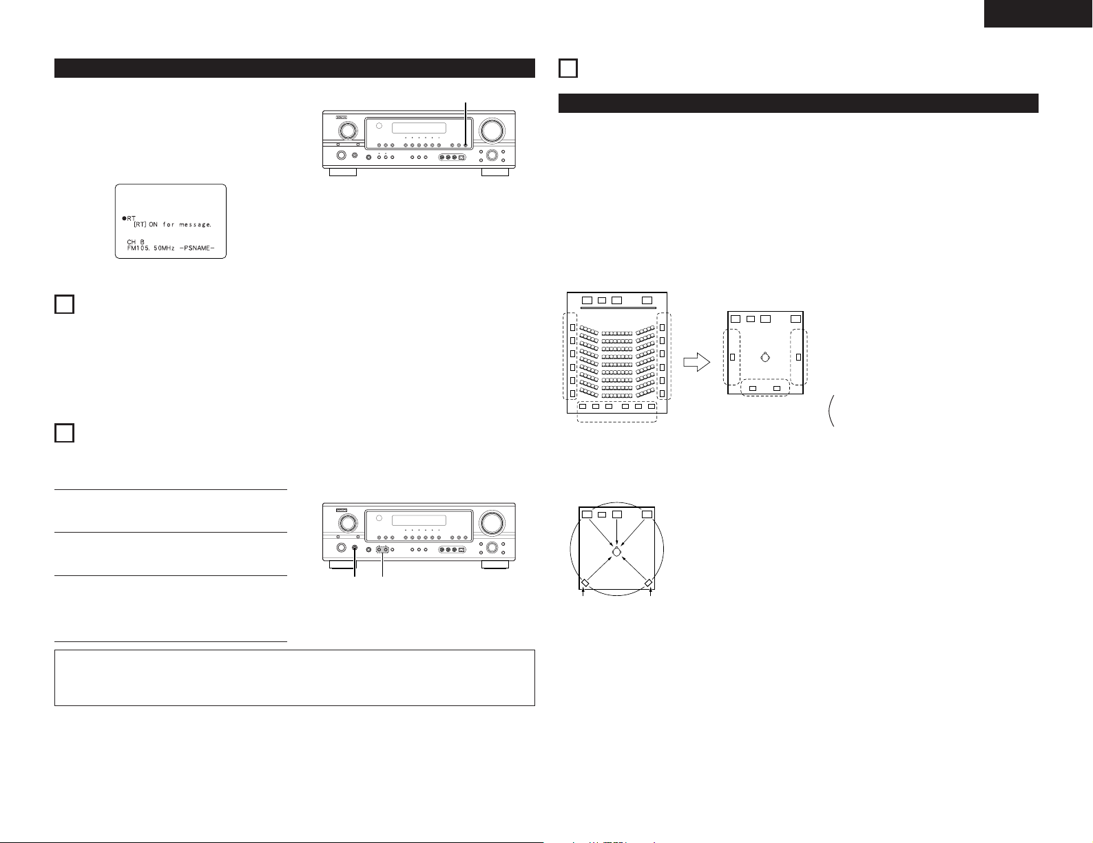
ENGLISH
FL CSWFR
FL CSWFR
SL SR
SB
SL SR
SB
SL: Surround L channel
SR: Surround R channel
SB: Surround back channel (1 spkr or 2 spkrs)
FL CSWFR
SL SR
1, 2
2
“RT”
RT (Radio Text)
“RT” appears on the display when radio text data is
received.
When the RT button is pressed while receiving an RDS
broadcast station, the text data broadcast from the
station is displayed. To turn the display off, press the
RT button again. If no text data is being broadcast,
“NO TEXT DATA” is displayed.
14
LAST FUNCTION MEMORY
• This unit is equipped with a last function memory which stores the input and output setting conditions as they
were immediately before the power is switched off.
This function eliminates the need to perform complicated resettings when the power is switched on.
• The unit is also equipped with a back-up memory. This function provides approximately one week of memory
storage when the main unit’s power switch is off and with the power cord disconnected.
15
INITIALIZATION OF THE MICROPROCESSOR
When the indication of the display is not normal or when the operation of the unit does not shows the reasonable
result, the initialization of the microprocessor is required by the following procedure.
Switch off the unit using the main unit’s power
1
switch.
Hold the following SPEAKER A button and B
2
button, and turn the main unit’s power switch.
16
ADDITIONAL INFORMATION
Optimum surround sound for different sources
There are currently various types of multi-channel signals (signals or formats with more than two channels).
2 Types of multi-channel signals
Dolby Digital, Dolby Pro Logic, DTS, high definition 3-1 signals (Japan MUSE Hi-Vision audio), DVD-Audio,
SACD (Super Audio CD), MPEG multi-channel audio, etc.
“Source” here does not refer to the type of signal (format) but the recorded content. Sources can be divided
into two major categories.
2 Types of sources
• Movie audio Signals created to be played in movie theaters. In general sound is recorded to be played
Movie theater sound field
Multiple surround speakers
(For 6.1-channel system)
• Other types of audio These signals are designed to recreate a 360° sound field using three to five
in movie theaters equipped with multiple surround speakers, regardless of the format
(Dolby Digital, DTS, etc.).
Listening room sound field
In this case it is important to achieve the same
sense of expansion as in a movie theater with the
surround channels.
To do so, in some cases the number of surround
speakers is increased (to four or eight) or speakers
with bipolar or dipolar properties are used.
speakers.
In this case the speakers should surround the listener from all sides to create a
uniform sound field from 360°. Ideally the surround speakers should function as
“point” sound sources in the same way as the front speakers.
Check that the entire display is flashing with an
3
interval of about 1 second, and release your
fingers from the 2 buttons and the microprocessor
will be initialized.
NOTES:
• If step 3 does not work, start over from step 1.
• If the microprocessor has been reset, all the button settings are reset to the default values (the values set
upon shipment from the factory).
These two types of sources thus have different properties, and different speaker settings, particularly for the
surround speakers, are required in order to achieve the ideal sound.
35
Page 36

ENGLISH
FL CSWFR FL CSWFR
SR chSL ch
SL ch SR ch
SB ch
Surround back speakers
A 6.1-channel system is a conventional 5.1-channel system to which the “surround back” (SB) channel has been
added. This makes it easy to achieve sound positioned directly behind the listener, something that was previously
difficult with sources designed for conventional multi surround speakers. In addition, the acoustic image
extending between the sides and the rear is narrowed, thus greatly improving the expression of the surround
signals for sounds moving from the sides to the back and from the front to the point directly behind the listening
position.
Change of positioning and acoustic image
with 5.1-channel systems
Movement of acoustic image from SR to SL
With this set, speaker(s) for 1 or 2 channels are required to achieve a 6.1-channel system (DTS-ES, etc.). Adding
these speakers, however, increases the surround effect not only with sources recorded in 6.1 channels but also
with conventional 2- to 5.1-channel sources. Furthermore, all the DENON original surround modes (see page 28)
are compatible with 7.1-channel playback, so you can enjoy 7.1-channel sound with any signal source.
2 Number of surround back speakers
Though the surround back channel only consists of 1 channel of playback signals for 6.1-channel sources
(DTS-ES, etc.), we recommend using two speakers. When using speakers with dipolar characteristics in
particular, it is essential to use two speakers.
Using two speakers results in a smoother blend with the sound of the surround channels and better sound
positioning of the surround back channel when listening from a position other than the center.
2 Placement of the surround left and right channels when using surround back speakers
Using surround back speakers greatly improves the positioning of the sound at the rear. Because of this, the
surround left and right channels play an important role in achieving a smooth transition of the acoustic image
from the front to the back. As shown on the diagram above, in a movie theater the surround signals are also
produced from diagonally in front of the listeners, creating an acoustic image as if the sound were floating in
space.
To achieve these effects, we recommend placing the speakers for the surround left and right channels slightly
more towards the front than with conventional surround systems. Doing so sometimes increases the
surround effect when playing conventional 5.1-channel sources in the 6.1 surround or DTS-ES Matrix 6.1
mode. Check the surround effects of the various modes before selecting the surround mode.
Change of positioning and acoustic image
with 6.1-channel systems
Movement of acoustic image from SR to SB to SL
Speaker setting examples
Here we describe a number of speaker settings for different purposes. Use these examples as guides to set up
your system according to the type of speakers used and the main usage purpose.
1. DTS-ES compatible system (using surround back speakers)
(1) Basic setting for primarily watching movies
This is recommended when mainly playing movies and using regular single way or 2-way speakers for the
surround speakers.
Front speakers
Center speaker
Monitor
Subwoofer
60°
Surround
speakers
60°
Surround back speakers
As seen from above
(2) Setting for primarily watching movies using diffusion type speakers for the surround speakers
For the greatest sense of surround sound envelopment, diffuse radiation speakers such as bipolar types,
or dipolar types, provide a wider dispersion than is possible to obtain from a direct radiating speaker
(monopolar). Place these speakers at either side of the prime listening position, mounted above ear level.
Path of the surround sound
from the speakers to the
listening position
Surround
speakers
60°
Surround back speakers
As seen from above
• Set the front speakers with their front
surfaces as flush with the TV or monitor
screen as possible. Set the center speaker
between the front left and right speakers and
no further from the listening position than the
front speakers.
• Consult the owner’s manual for your
subwoofer for advice on placing the
Front speaker
As seen from the side
Surround
speaker
Surround back
speaker
60 to
90 cm
Point slightly
downwards
subwoofer within the listening room.
• If the surround speakers are direct-radiating (monopolar) then place them
slightly behind and at an angle to the listening position and parallel to the walls
at a position 60 to 90 cm above ear level at the prime listening position.
• When using two surround back speakers, place them at the back facing the
front at a narrower distance than the front left and right speakers. When using
one surround back speaker, place it at the rear center facing the front at a
slightly higher position (0 to 20 cm) than the surround speakers.
• We recommend installing the surround back speaker(s) at a slightly downward
facing angle. This effectively prevents the surround back channel signals from
reflecting off the monitor or screen at the front center, resulting in interference
and making the sense of movement from the front to the back less sharp.
• Set the front speakers, center speaker and
subwoofer in the same positions as in
example (1).
• It is best to place the surround speakers
directly at the side or slightly to the front of
the viewing position, and 60 to 90 cm above
the ears.
• Same as surround back speaker installation
Front speaker
As seen from the side
Surround
speaker
Surround back
speaker
60 to
90 cm
Point slightly
downwards
method (1).
Using dipolar speakers for the surround back speakers as well is more effective.
• The signals from the surround channels reflect off the walls as shown on the
diagram at the left, creating an enveloping and realistic surround sound
presentation.
36
Page 37

ENGLISH
2. When not using surround back speakers
Front speakers
Center speaker
Monitor
Subwoofer
60°
• Set the front speakers with their front surfaces as
flush with the TV or monitor screen as possible. Set
the center speaker between the front left and right
speakers and no further from the listening position
than the front speakers.
• Consult the owner’s manual for your subwoofer for
advice on placing the subwoofer within the listening
room.
Surround speaker
Front speaker
60 to
90 cm
As seen from the side
• If the surround speakers are direct-radiating
120°
Surround speakers
As seen from above
(monopolar) then place them slightly behind and at
an angle to the listening position and parallel to the
walls at a position 60 to 90 cm above ear level at
the prime listening position.
Surround
The AVR-1905 is equipped with a digital signal processing circuit that lets you play program sources in the
surround mode to achieve the same sense of presence as in a movie theater.
Dolby Surround
(1) Dolby Digital
Dolby Digital is the multi-channel digital signal format developed by Dolby Laboratories.
Dolby Digital consists of up to “5.1” channels - front left, front right, center, surround left, surround right, and
an additional channel exclusively reserved for additional deep bass sound effects (the Low Frequency Effects
– LFE – channel, also called the “.1” channel, containing bass frequencies of up to 120 Hz).
Unlike the analog Dolby Pro Logic format, Dolby Digital’s main channels can all contain full range sound
information, from the lowest bass, up to the highest frequencies – 22 kHz. The signals within each channel
are distinct from the others, allowing pinpoint sound imaging, and Dolby Digital offers tremendous dynamic
range from the most powerful sound effects to the quietest, softest sounds, free from noise and distortion.
2 Dolby Digital and Dolby Pro Logic
2 Dolby Digital compatible media and playback methods
Marks indicating Dolby Digital compatibility: .
The following are general examples. Also refer to the player’s operating instructions.
Media
LD (VDP)
DVD
(satellite broadcasts, CATV, etc.)
Others
Dolby Digital output jacks
Coaxial Dolby Digital RF output jack
Optical or coaxial digital output
(same as for PCM) 2
Optical or coaxial digital output
1
(same as for PCM)
Playback method (reference page)
Set the input mode to “AUTO”.
(Page 20)
Set the input mode to “AUTO”.
(Page 20)
Set the input mode to “AUTO”.
(Page 20)
1 Please use a commercially available adapter when connecting the Dolby Digital RF output jack of the
LD player to the digital input jack.
Please refer to the instruction manual of the adapter when making connection.
2 Some DVD digital outputs have the function of switching the Dolby Digital signal output method
between “bit stream” and “(convert to) PCM”. When playing in Dolby Digital surround on the AVR1905, switch the DVD player’s output mode to “bit stream”. In some cases players are equipped with
both “bit stream + PCM” and “PCM only” digital outputs. In this case connect the “bit stream + PCM”
jacks to the AVR-1905.
(2) Dolby Pro Logic II x
• Dolby Pro Logic
IIx furthers the matrix decoding technology of Dolby Pro Logic II to decode audio signals
recorded on two channels into up to 7.1 playback channels, including the surround back channel. Dolby Pro
Logic
IIx also allows 5.1-channel sources to be played in up to 7.1 channels.
The mode can be selected according to the source. The Music mode is best suited for playing music, the
Cinema mode for playing movies, and the Game mode for playing games. The Game mode can only be
used with 2-channel audio sources.
Comparison of home surround
systems
No. recorded channels (elements)
No. playback channels
Playback channels (max.)
Audio processing
High frequency playback limit of
surround channel
Dolby Digital
5.1 ch
5.1 ch
L, R, C, SL, SR, SW
Digital discrete processing
Dolby Digital encoding/decoding
20 kHz
Dolby Pro Logic
2 ch
4 ch
L, R, C, S (SW - recommended)
Analog matrix processing Dolby
Surround
7 kHz
37
Page 38

ENGLISH
(3) Dolby Pro Logic
• Dolby Pro Logic II is a new multi-channel playback format developed by Dolby Laboratories using feedback
logic steering technology and offering improvements over conventional Dolby Pro Logic circuits.
• Dolby Pro Logic
stereo sources into five channels (front left, front right, center, surround left and surround right) to achieve
surround sound.
• Whereas with conventional Dolby Pro Logic the surround channel playback frequency band was limited,
Dolby Pro Logic
were monaural (the surround left and right channels were the same) with previous Dolby Pro Logic, but
Dolby Pro Logic
• Various parameters can be set according to the type of source and the contents, so it is possible to achieve
optimum decoding (see page 30).
Sources recorded in Dolby Surround
These are sources in which three or more channels of surround have been recorded as two channels of
signals using Dolby Surround encoding technology.
Dolby Surround is used for the sound tracks of movies recorded on DVDs, LDs and Video cassettes to be
played on stereo VCRs, as well as for the stereo broadcast signals of FM radio, TV, satellite broadcasts and
cable TV.
Decoding these signals with Dolby Pro Logic
playback. The signals can also be played on ordinary stereo equipment, in which case they provide normal
stereo sound.
There are two types of DVD Dolby surround recording signals.
q 2-channel PCM stereo signals
w 2-channel Dolby Digital signals
When either of these signals is input to the AVR-1905, the surround mode is automatically set to Dolby
Pro Logic
2 Sources recorded in Dolby Surround are indicated with the logo mark shown below
Dolby Surround support mark:
Manufactured under license from Dolby Laboratories.
“Dolby”, “Pro Logic” and the double-D symbol are trademarks of Dolby Laboratories.
II
II can be used to decode not only sources recorded in Dolby Surround ( ) but also regular
II offers a wider band range (20 Hz to 20 kHz or greater). In addition, the surround channels
II they are played as stereo signals.
II makes it possible to achieve multi-channel surround
II when the “DOLBY/DTS SURROUND” mode is selected.
DTS Digital Surround
Digital Theater Surround (also called simply DTS) is a multi-channel digital signal format developed by Digital
Theater Systems.
DTS offers the same “5.1” playback channels as Dolby Digital (front left, front right and center, surround left and
surround right) as well as the stereo 2-channel mode. The signals for the different channels are fully independent,
eliminating the risk of deterioration of sound quality due to interference between signals, crosstalk, etc.
DTS features a relatively higher bit rate as compared to Dolby Digital (1234 kbps for CDs and LDs, 1536 kbps for
DVDs) so it operates with a relatively low compression rate. Because of this the amount of data is great, and
when DTS playback is used in movie theaters, a separate CD-ROM synchronized with the film is played.
With LDs and DVDs, there is of course no need for an extra disc; the pictures and sound can be recorded
simultaneously on the same disc, so the discs can be handled in the same way as discs with other formats.
There are also music CDs recorded in DTS. These CDs include 5.1-channel surround signals (compared to two
channels on current CDs). They do not include picture data, but they offer surround playback on CD players that
are equipped with digital outputs (PCM type digital output required).
DTS surround track playback offers the same intricate, grand sound as in a movie theater, right in your own
listening room.
2 DTS compatible media and playback methods
Marks indicating DTS compatibility: and .
The following are general examples. Also refer to the player’s operating instructions.
Media
CD
LD (VDP)
DVD
1 DTS signals are recorded in the same way on CDs and LDs as PCM signals. Because of this, the un-
decoded DTS signals are output as random “hissy” noise from the CD or LD player’s analog outputs. If
this noise is played with the amplifier set at a very high volume, it may possibly cause damage to the
speakers. To avoid this, be sure to switch the input mode to “AUTO” or “DTS” before playing CDs or LDs
recorded in DTS. Also, never switch the input mode to “ANALOG” or “PCM” during playback. The same
holds true when playing CDs or LDs on a DVD player or LD/DVD compatible player. For DVDs, the DTS
signals are recorded in a special way so this problem does not occur.
2 The signals provided at the digital outputs of a CD or LD player may undergo some sort of internal signal
processing (output level adjustment, sampling frequency conversion, etc.). In this case the DTS-encoded
signals may be processed erroneously, in which case they cannot be decoded by the AVR-1905, or may
only produce noise. Before playing DTS signals for the first time, turn down the master volume to a low
level, start playing the DTS disc, then check whether the DTS indicator on the AVR-1905 (see page 20)
lights before turning up the master volume.
3 A DVD player with DTS-compatible digital output is required to play DTS DVDs. A DTS Digital Output logo
is featured on the front panel of compatible DVD players. Recent DENON DVD player models feature DTScompatible digital output – consult the player’s owner’s manual for information on configuring the digital
output for DTS playback of DTS-encoded DVDs.
Dolby Digital output jacks
Optical or coaxial digital output
(same as for PCM) 2
Optical or coaxial digital output
(same as for PCM) 2
Optical or coaxial digital output
(same as for PCM) 3
Playback method (reference page)
Set the input mode to “AUTO” or “DTS” (page 20).
Never set the mode to “ANALOG” or “PCM”. 1
Set the input mode to “AUTO” or “DTS” (page 20).
Never set the mode to “ANALOG” or “PCM”. 1
Set the input mode to “AUTO” or “DTS” (page 20).
38
MANUFACTURED UNDER LICENSE FROM DIGITAL THEATER SYSTEMS, INC.
U.S. PAT. NO’S. 5,451,942; 5,956,674; 5,974,380; 5,978,762; 6,226,616; 6,487,535 AND OTHER U.S. AND
WORLD–WIDE PATENTS ISSUED AND PENDING.
“DTS”, “DTS–ES”, “Neo:6”, AND “DTS 96/24” ARE TRADEMARKS OF DIGITAL THEATER SYSTEMS, INC.
© 1996, 2003 DIGITAL THEATER SYSTEMS, INC. ALL RIGHTS RESERVED.
Page 39

ENGLISH
DTS-ES Extended Surround™
DTS-ES Extended Surround is a new multi-channel digital signal format developed by Digital Theater Systems
Inc. While offering high compatibility with the conventional DTS Digital Surround format, DTS-ES Extended
Surround greatly improves the 360-degree surround impression and space expression thanks to further expanded
surround signals. This format has been used professionally in movie theaters since 1999.
In addition to the 5.1 surround channels (FL, FR, C, SL, SR and LFE), DTS-ES Extended Surround also offers the
SB (Surround Back, sometimes also referred to as “surround center”) channel for surround playback with a total
of 6.1 channels. DTS-ES Extended Surround includes two signal formats with different surround signal recording
methods, as described below.
2 DTS-ES™ Discrete 6.1
DTS-ES Discrete 6.1 is the newest recording format. With it, all 6.1 channels (including the SB channel) are
recorded independently using a digital discrete system. The main feature of this format is that because the
SL, SR and SB channels are fully independent, the sound can be designed with total freedom and it is possible
to achieve a sense that the acoustic images are moving about freely among the background sounds
surrounding the listener from 360 degrees.
Though maximum performance is achieved when sound tracks recorded with this system are played using a
DTS-ES decoder, when played with a conventional DTS decoder the SB channel signals are automatically
down-mixed to the SL and SR channels, so none of the signal components are lost.
2 DTS-ES™ Matrix 6.1
With this format, the additional SB channel signals undergo matrix encoding and are input to the SL and SR
channels beforehand. Upon playback they are decoded to the SL, SR and SB channels. The performance of
the encoder used at the time of recording can be fully matched using a high precision digital matrix decoder
developed by DTS, thereby achieving surround sound more faithful to the producer’s sound design aims than
with conventional 5.1- or 6.1-channel systems.
In addition, the bit stream format is 100% compatible with conventional DTS signals, so the effect of the
Matrix 6.1 format can be achieved even with 5.1-channel signal sources. Of course it is also possible to play
DTS-ES Matrix 6.1 encoded sources with a DTS 5.1-channel decoder.
When DTS-ES Discrete 6.1 or Matrix 6.1 encoded sources are decoded with a DTS-ES decoder, the format is
automatically detected upon decoding and the optimum playing mode is selected. However, some Matrix 6.1
sources may be detected as having a 5.1-channel format, so the DTS-ES Matrix 6.1 mode must be set manually
to play these sources.
(For instructions on selecting the surround mode, see page 26.)
The DTS-ES decoder includes another function, the DTS Neo:6 surround mode for 6.1-channel playback of digital
PCM and analog signal sources.
DTS 96/24
The sampling frequency, number of bits and number of channels used for recording of music, etc., in studios has
been increasing in recent years, and there are a growing number of high quality signal sources, including 96
kHz/24 bit 5.1-channel sources.
For example, there are high picture/sound quality DVD video sources with 96 kHz/24 bit stereo PCM audio tracks.
However, because the data rate for these audio tracks is extremely high, there are limits to recording them on
two channels only, and since the quality of the pictures must be restricted it is common to only include still
pictures.
In addition, 96 kHz/24 bit 5.1-channel surround is possible with DVD audio sources, but DVD audio players are
required to play them with this high quality.
DTS 96/24 is a multi-channel digital signal format developed by Digital Theater Systems Inc. in order to deal with
this situation.
Conventional surround formats used sampling frequencies of 48 or 44.1 kHz, so 20 kHz was about the maximum
playback signal frequency. With DTS 96/24, the sampling frequency is increased to 96 or 88.2 kHz to achieve a
wide frequency range of over 40 kHz.
In addition, DTS 96/24 has a resolution of 24 bits, resulting in the same frequency band and dynamic range as 96
kHz/24 bit PCM.
As with conventional DTS Surround, DTS 96/24 is compatible with a maximum of 5.1 channels, so sources
recorded using DTS 96/24 can be played in high sampling frequency, multiple channel audio with such normal
media as DVD videos and CDs.
Thus, with DTS 96/24, the same 96 kHz/24 bit multi-channel surround sound as with DVD-Audio can be achieved
while viewing DVD-Video images on a conventional DVD-Video player ( 1). Furthermore, with DTS 96/24
compatible CDs, 88.2 kHz/24 bit multi-channel surround can be achieved using normal CD/LD players ( 1).
Even with the high quality multi-channel signals, the recording time is the same as with conventional DTS
surround sources.
What’s more, DTS 96/24 is fully compatible with the conventional DTS surround format, so DTS 96/24 signal
sources can be played with a sampling frequency of 48 kHz or 44.1 kHz on conventional DTS or DTS-ES surround
decoders ( 2).
1 A DVD player with DTS digital output capabilities (for CD/LD players, a player with digital outputs for
conventional DTS CDs/LDs) and a disc recorded in DTS 96/24 are required.
2 The resolution is 24 or 20 bits, depending on the decoder.
2 DTS Neo:6™ surround
This mode applies conventional 2-channel signals to the high precision digital matrix decoder used for DTS-ES
Matrix 6.1 to achieve 6.1-channel surround playback. High precision input signal detection and matrix
processing enable full band reproduction (frequency response of 20 Hz to 20 kHz or greater) for all 6.1
channels, and separation between the different channels is improved to the same level as that of a digital
discrete system.
DTS Neo:6 surround includes two modes for selecting the optimum decoding for the signal source.
• DTS Neo:6 Cinema
This mode is optimum for playing movies. Decoding is performed with emphasis on separation performance
to achieve the same atmosphere with 2-channel sources as with 6.1-channel sources.
This mode is effective for playing sources recorded in conventional surround formats as well, because the
in-phase component is assigned mainly to the center channel (C) and the reversed phase component to the
surround (SL, SR and SB channels).
• DTS Neo:6 Music
This mode is suited mainly for playing music. Changes in the sound quality are reduced by decoding with
emphasis on the front channel signals (FL and FR), and a natural sense of expansion is given to the sound
field by the effect of the surround signals output from the center (C) and surround (SL, SR and SB) channels.
39
Page 40

ENGLISH
17
TROUBLESHOOTING
If a problem should arise,first check the following.
1. Are the connections correct ?
2. Have you operated the receiver according to the Operating Instructions ?
3. Are the speakers, turntable and other components operating property ?
If this unit is not operating properly, check the items listed in the table below. Should the problem persist, there
may be a malfunction.
Disconnect the power immediately and contact your store of purchase.
Symptom Cause Measures Page
DISPLAY not lit and
sound not produced
when power switch
set to on.
DISPLAY lit but sound
not produced.
DISPLAY not lit and
power indicator is
flashing rapidly.
Sound produced only
from one channel.
Positions of
instruments reversed
Common problems when listening to the CD, records, tapes and FM broadcasts, etc.
during stereo playback.
• Power cord not plugged in securely. • Check the insertion of the power cord
• Speaker cords not securely connected.
• Improper position of the audio function
button.
• Volume control set to minimum.
• MUTING is on.
• Digital signals not input Digital input
selected.
• Speaker terminals are short-circuited.
• Block the ventilation holes of the set.
• The unit is operating at continuous high
power conditions and/or inadequate
ventilation.
• Incomplete connection of speaker cords.
• Incomplete connection of input/output
cords.
• Reverse connections of left and right
speakers or left and right input/output
cords.
plug.
• Turn the power on with the remote control
unit after turning the POWER switch on.
• Connect securely.
• Set to a suitable position.
• Turn volume up to suitable level.
• Switch off MUTING.
• Input digital signals or select input jacks
to which digital signals are being input.
• Switch power off, connect speakers
properly, then switch power back on.
• Turn off the set’s power, then ventilate it
well to cool it down.
Once the set is cooled down, turn the
power back on.
• Turn off the set’s power, then ventilate it
well to cool it down.
Once the set is cooled down, turn the
power back on.
• Connect securely.
• Connect securely.
• Check left and right connections. 9
5
19
8, 9
20
20
22
20
8, 9
5, 8
5, 8
8, 9
5 ~ 9
Symptom Cause Measures Page
Humming noise
produced when record
is playing.
Howling noise
produced when
volume is high.
When playing records
Sound is distorted.
Volume is weak.
This unit does not
operate properly when
remote control unit is
used.
Remote control unit
• Ground wire of turntable not connected
properly.
• Incomplete PHONO jack connection.
• TV or radio transmission antenna nearby.
• Turntable and speaker systems too close
together.
• Floor is unstable and vibrates easily.
• Stylus pressure too weak.
• Dust or dirt on stylus.
• Cartridge defective.
• MC cartridge being used. • Replace with MM cartridge or use a
• Batteries dead.
• Remote control unit too far from this unit.
• Obstacle between this unit and remote
control unit.
• Different button is being pressed.
• < and > ends of battery inserted in
reverse.
• Connect securely.
• Connect securely.
• Contact your store of purchase.
• Separate as much as possible.
• Use cushions to absorb speaker vibrations
transmitted by floor. If turntable is not
equipped with insulators, use audio
insulators (commonly available).
• Apply proper stylus pressure.
• Check stylus.
• Replace cartridge.
head amplifier or step-up transformer.
• Replace with new batteries.
• Move closer.
• Remove obstacle.
• Press the proper button.
• Insert batteries properly.
5
5
—
—
—
—
—
—
5
10
10
10
—
10
40
Page 41

18
SPECIFICATIONS
2 Audio section
• Power amplifier
Rated output: Front: 80 W + 80 W (8 Ω/ohms, 20 Hz ~ 20 kHz with 0.08% T.H.D.)
Center: 80 W (8 Ω/ohms, 20 Hz ~ 20 kHz with 0.08% T.H.D.)
Surround: 80 W + 80 W (8 Ω/ohms, 20 Hz ~ 20 kHz with 0.08% T.H.D.)
Surround Back: 80 W + 80 W (8 Ω/ohms, 20 Hz ~ 20 kHz with 0.08% T.H.D.)
Output terminals: Front: A or B 16 ~ 16 Ω/ohms
• Analog
Input sensitivity / input impedance: 200 mV / 47 kΩ/kohms
Frequency response: 10 Hz ~ 100 kHz: +1, –3 dB (DIRECT mode)
S/N ratio: 98 dB (IHF-A weighted) (DIRECT mode)
2 Video section
• Standard video jacks
Input / output level and impedance: 1 Vp-p, 75 Ω/ohms
Frequency response: 5 Hz ~ 10 MHz — +1, –3 dB
• S-video jacks
Input / output level and impedance: Y (brightness) signal — 1 Vp-p, 75 Ω/ohms
Frequency response: 5 Hz ~ 10 MHz — +1, –3 dB
• Color component video jacks
Input / output level and impedance: Y (brightness) signal — 1 Vp-p, 75 Ω/ohms
Frequency response: 5 ~ 30 MHz — +1, –3 dB
2 Tuner section [FM] (note: µV at 75 Ω/ohms, 0 dBf=1 x 10
Receiving Range: 87.50 MHz ~ 108.00 MHz 522 kHz ~ 1611 kHz
Usable Sensitivity: 1.0 µV (11.2 dBf) 18 µV
50 dB Quieting Sensitivity: MONO 1.6 µV (15.3 dBf)
S/N ratio: MONO 77 dB (IHF-A weighted)
Total Harmonic Distortion: MONO 0.15 % (1 kHz)
Center, Surround, Surr. Back: 16 ~ 16 Ω/ohms
C (color) signal — 0.286 Vp-p, 75 Ω/ohms
B/CB (blue) signal — 0.7 Vp-p, 75 Ω/ohms
P
PR/CR (red) signal — 0.7Vp-p, 75 Ω/ohms
STEREO 23 µV (38.5 dBf)
STEREO 72 dB (IHF-A weighted)
STEREO 0.3 % (1 kHz)
115 W + 115 W (6 Ω/ohms, 1 kHz with 0.7% T.H.D.)
115 W (6 Ω/ohms, 1 kHz with 0.7% T.H.D.)
115 W + 115 W (6 Ω/ohms, 1 kHz with 0.7% T.H.D.)
115 W + 115 W (6 Ω/ohms, 1 kHz with 0.7% T.H.D.)
A + B 12 ~ 16 Ω/ohms
15
–
W) [AM]
ENGLISH
2 General
Power supply: AC 230 V, 50 Hz
Power consumption: 260 W
1 W Max (Standby)
Maximum external dimensions: 434 (W) x 147 (H) x 417 (D) mm
Mass: 11.4 kg
2 Remote control unit (RC-979)
Batteries: R6P/AA Type (two batteries)
External dimensions: 55 (W) x 225 (H) x 34.5 (D) mm
Mass: 165 g (including batteries)
* For purposes of improvement, specifications and design are subject to change without notice.
41
Page 42

SVENSKANEDERLANDSESPAÑOLITALIANOFRANCAISDEUTSCHENGLISH
List of Preset Codes / Liste von voreingestellten Codes / Liste de codes
préréglés / Lista dei codici pre-regolati / Lista de Códigos Pre-ajustados /
Lijst van vooringestelde codes / Förteckning över förinställda koder
DVD
Denon 014, *[111]
Aiwa 009
Hitachi 010
JVC 006, 011
Konka 012, 013
Magnavox 005
Mitsubishi 004
Panasonic 014
Philips 005, 015, 016, 017
Pioneer 003, 008
Sanyo 018
Sony 002, 019, 020
Toshiba 001, 021, 022
Zenith 023
VDP
Denon 028, 029, 112
Magnavox 026
Mitsubishi 028
Panasonic 029, 030
Philips 026
Pioneer 028, 031
RCA 032
Sony 033, 034, 035, 036
VCR
Admiral 081
Aiko 095
Aiwa 009
Akai 026, 027, 070, 072, 082, 083,
084
Alba 055
Amstrad 009
ASA 042
Asha 087
Audio Dynamic 005, 085
Audiovox 088
Beaumark 087
Broksonic 086, 093
Calix 088
Candle 006, 087, 088, 089, 090
Canon 049, 057
Capehart 025, 055, 056, 071
Carver 015
CCE 095
Citizen 006, 007, 087, 088, 089, 090,
095
Craig 007, 087, 088, 091, 115
Curtis Mathes 006, 049, 073, 080, 087, 090,
092
Cybernex 087
Daewoo 025, 055, 059, 074, 089, 093,
095, 096
Daytron 025, 055
DBX 005, 085
Dumont 053
Dynatech 009
Electrohome 001, 088, 097
Electrophonic 088
Emerson 001, 009, 017, 027, 086, 088,
089, 092, 093, 097, 100, 101,
102, 103, 104, 117
Fisher 009, 028, 031, 053, 054, 091,
099, 115
GE 007, 011, 049, 050, 051, 052,
073, 080, 087
Go Video 047, 048
Goldstar 000, 006, 012, 062, 088
Gradiente 094
Grundig 042
Harley Davidson 094
Harman Kardon 040, 062
Hi-Q 091
Hitachi 009, 013, 023, 026, 058,*[108],
109, 110, 111
JC Penny 004, 005, 007, 023, 028, 049,
062, 085, 087, 088
Jensen 013, 026
JVC 004, 005, 006, 026, 029, 043,
044, 045, 046, 085
Kenwood 004, 005, 006, 026, 029, 033,
045, 085, 090
Kodak 088
Lloyd 009, 094
LXI 088
Magnavox 015, 016, 042, 049, 063, 106
Magnin 087
Marantz 004, 005, 006, 015, 042, 049,
085, 090
Marta 088
MEI 049
Memorex 009, 033, 049, 053, 060, 081,
087, 088, 091, 094, 115
Metz 123, 124, 125, 126, 127, 128
MGA 001, 017, 027, 041, 097
MGN Technology 087
Midland 011
Minolta 013, 023
Mitsubishi 001, 003, 008, 013, 014, 017,
027, 029, 039, 040, 041, 045,
097
Motorola 081
Montgomery Ward
MTC 009, 087, 094
Multitech 007, 009, 011, 087, 090, 094
NAD 038
NEC 004, 005, 006, 018, 026, 029,
Nikko 088
Noblex 087
Optimus 081, 088
Optonica 021
Panasonic 024, 049, 064, 066, 067, 068,
Perdio 009
Pentax 009, 013, 023, 058, 090
Philco 015, 016, 049
Philips 015, 021, 042, 049, 105
Pilot 088
Pioneer 005, 013, 029, 036, 037, 038,
Portland 025, 055, 090
Proscan 063, 080
Pulsar 060
Quartz 033
Quasar 034, 035, 049
Radio Shack 001, 002, 021, 081, 087, 088,
Radix 088
Randex 088
RCA 007, 013, 019, 023, 058, 063,
Realistic 009, 021, 031, 033, 049, 053,
Ricoh 055
Salora 033, 041
Samsung 007, 011, 051, 059, 070, 083,
Sanky 081
Sansui 005, 026, 029, 045, 061, 085,
Sanyo 032, 033, 053, 087, 091, 115,
001, 002, 007, 009, 049,
063, 081, 115, 117
045, 061, 062, 085
069, 107
045, 085
091, 094, 097, 098, 115
064, 065, 073, 080, 082, 087
081, 087, 088, 091, 094, 097,
098
087, 089, 113
114
116
SBR 042
Scott 017, 020, 086, 089, 093, 117
Sears 013, 023, 028, 031, 033, 053,
054, 088, 091, 098, 099, 115
Sentra 055
Sharp 001, 002, 021, 097
Shogun 087
Sony 075, 076, 077, 078, 079, 121,
122
STS 023
Sylvania 009, 015, 016, 017, 041, 049,
094
Symphonic 009, 094
Tandy 009
Tashiko 009, 088
Tatung 004, 026, 030
Teac 004, 009, 026, 094
Technics 024, 049
Teknika 009, 010, 022, 049, 088, 094
TMK 087, 092
Toshiba 013, 017, 020, 041, 059, 089,
098, 099, 117
Totevision 007, 087, 088
Unirech 087
Vecrtor Research 005, 062, 085, 089, 090
Victor 005, 045, 046, 085
Video Concepts 005, 027, 085, 089, 090
Videosonic 007, 087
Wards 013, 021, 023, 087, 088, 089,
091, 094, 097, 118, 119, 120
XR-1000 094
Yamaha 004, 005, 006, 026, 062, 085
Zenith 060, 078, 079
TV
Admiral 045, 121
Adventura 122
Aiko 054
Akai 016, 027, 046
Alleron 062
A-Mark 007
Amtron 061
Anam 006, 007, 036
Anam National 061, 147
AOC 003, 007, 033, 038, 039, 047,
048, 049, 133
Archer 007
Audiovox 007, 061
Bauer 155
Belcor 047
Bell & Howell 045, 118
276
Page 43

SVENSKA NEDERLANDS ESPAÑOL ITALIANO FRANCAIS DEUTSCH ENGLISH
Bradford 061
Brockwood 003, 047
Candle 003, 030, 031, 032, 038, 047,
049, 050, 122
Capehart 003
Celebrity 046
Circuit City 003
Citizen 029, 030, 031, 032, 034, 038,
047, 049, 050, 054, 061, 095,
122, 123
Concerto 031, 047, 049
Colortyme 003, 047, 049, 135
Contec 013, 051, 052, 061
Cony 051, 052, 061
Craig 004, 061
Crown 029
Curtis Mathes 029, 034, 038, 044, 047, 049,
053, 095, 118
Daewoo 027, 029, 039, 048, 049, 054,
055, 106, 107, 137
Daytron 003, 049
Dimensia 044
Dixi 007, 015, 027
Electroband 046
Electrohome 029, 056, 057, 058, 147
Elta 027
Emerson 029, 051, 059, 060, 061, 062,
118, 123, 124, 139, 148
Envision 038
Etron 027
Fisher 014, 021, 063, 064, 065, 118
Formenti 155
Fortress 012
Fujitsu 004, 062
Funai 004, 062
Futuretech 004
GE 020, 036, 037, 040, 044, 058,
066, 088, 119, 120, 125, 147
Goldstar 000, 015, 029, 031, 039, 048,
051, 056, 057, 067, 068, 069,
116
Grundy 062
Hitachi 029, 031, 051, 052, 070, 111,
112, 113, 124, *[134]
Hitachi Pay TV 151
Infinity 017, 071
Janeil 122
JBL 017, 071
JC Penny 020, 034, 039, 040, 041, 044,
048, 050, 058, 066, 069, 076,
088, 090, 095, 125, 136, 159
JCB 046
JVC 019, 051, 052, 072, 073, 091,
117, 126
Kawasho 018, 046
Kenwood 038, 056, 057
Kloss 010, 032
Kloss Novabeam 005, 122, 127, 131
KTV 074, 123
Loewe 071
Logik 144
Luxman 031
LXI 008, 014, 017, 024, 040, 044,
063, 071, 075, 076, 077, 118,
125
Magnavox 005, 010, 017, 030, 033, 038,
050, 056, 071, 078, 079, 085,
089, 108, 109, 110, 127, 131,
132, 145
Marantz 015, 017, 071, 080
Matsui 027
Memorex 014, 027, 045, 083, 118, 144
Metz 160, 161, 162, 163
MGA 001, 039, 048, 056, 057, 058,
065, 081, 083
Midland 125
Minutz 066
Mitsubishi 001, 016, 039, 048, 056, 057,
058, 065, 081, 082, 083, 105
Montgomery Ward
Motorola 121, 147
MTC 031, 034, 039, 048, 095
NAD 008, 075, 076, 128
National 002, 036, 061, 147
National Quenties
NEC 031, 038, 039, 048, 057, 084,
Nikko 054
NTC 054
Optimus 128
Optonica 011, 012, 093, 121
Orion 004, 139
Panasonic 002, 009, 017, 036, 037, 071,
Philco 005, 010, 030, 050, 051, 056,
Philips 005, 015, 017, 050, 051, 056,
Pioneer 124, 128, 142
Portland 054
011, 020, 144, 145, 146
002
086, 135, 147
141, 143, 147
079, 085, 127, 131, 132, 145,
147
078, 087, 088, 089, 131, 132,
147
Price Club 095
Proscan 040, 044, 125
Proton 035, 051, 092, 129
Pulsar 042
Quasar 036, 037, 074, 141
Radio Shack 011, 044, 063, 093, 118
RCA 040, 044, 125, 130, 137, 151,
152
Realistic 014, 063, 093, 118
Saisho 027
Samsung 003, 015, 034, 053, 055, 057,
094, 095, 136, 153
Sansui 139
Sanyo 013, 014, 021, 022, 063, 064,
081, 096
SBR 015
Schneider 015
Scott 062
Sears 008, 014, 021, 022, 023, 024,
025, 040, 052, 057, 062, 063,
064, 065, 073, 075, 076, 097,
098, 125, 159
Sharp 011, 012, 013, 026, 093, 099,
100, 104, 121
Siemens 013
Signature 045, 144
Simpson 050
Sony 043, 046, 138, 146, 150
Soundesign 030, 050, 062
Spectricon 007, 033
Squareview 004
Supre-Macy 032, 122
Supreme 046
Sylvania 005, 010, 017, 030, 078, 079,
085, 089, 101, 127, 131, 132,
145, 155
Symphonic 004, 148
Tandy 012, 121
Tatung 036, 124
Technics 037
Teknika 001, 030, 032, 034, 052, 054,
078, 083, 095, 144, 156, 157
Tera 035, 129
Toshiba 008, 014, 034, 063, 075, 076,
095, 097, 136, 158, 159
Universal 020, 066, 088
Victor 019, 073, 126
Video Concepts 016
Viking 032, 122
Wards 005, 045, 066, 078, 085, 088,
089, 093, 102, 103, 131, 132,
148
Zenith 042, 114, 115, 140, 144, 149
Zonda 007
CABLE
ABC 006, *[007], 008, 009
Archer 010, 011
Century 011
Citizen 011
Colour Voice 012, 013
Comtronic 014
Eastern 015
Garrard 011
Gemini 030, 033, 034
General Instrument
Hytex 006
Jasco 011
Jerrold 009, 016, 017, 026, 032
Magnavox 018
Movie Time 019
NSC 019
Oak 000, 006, 020
Panasonic 001, 005
Philips 011, 012, 013, 018, 021
Pioneer 002, 003, 022
RCA 029
Regency 015
Samsung 014, 023
Scientific Atlanta 004, 024, 025
Signal 014
SL Marx 014
Starcom 009
Stargate 014
Teleview 014
Tocom 007, 016
TV86 019
Unika 011
United Artists 006
Universal 010, 011
Viewstar 018, 019
Zenith 027, 028
030, 031, 032
DBS (SATELLITE)
Alphastar 054
Chaparral 035, 036
Dishnet 053
Drake 037, 038
Echostar Dish 062, 066
GE 048, 055, 056
General Instruments
Grundig 070, 071, 072, 073
Hitachi 058, 059
039, 040, 041
277
Page 44

SVENSKANEDERLANDSESPAÑOLITALIANOFRANCAISDEUTSCHENGLISH
Hughes Network 063, 064, 065, 069
JVC 057
Kathrein 074, 075, 076, 083
Magnavox 060
Nokia 070, 080, 084, 085, 086
Philips 060
Primestar 051
Proscan 048, 055, 056
RCA 048, 055, 056, 068
Realistic 042
Sierra I 036
Sierra II 036
Sierra III 036
Sony 049, 067
STS1 043
STS2 044
STS3 045
SRS4 046
Technisat 077, 078, 079, 081, 082
Toshiba 047, 050
Uniden 061
CD
Denon *[111]
Aiwa 001, 035, 043
Burmster 002
Carver 003, 035
Emerson 004, 005, 006, 007
Fisher 003, 008, 009, 010
JVC 018, 019
Kenwood 011, 012, 013, 014, 017
Magnavox 006, 015, 035
Marantz 016, 028, 035
MCS 016, 024
Onkyo 025, 027
Optimus 017, 020, 021, 022, 023
Philips 014, 032, 033, 035
Pioneer 006, 022, 030
Sears 006
Sony 023, 031
Teac 002, 009, 028
Technics 016, 029, 036
Wards 035, 037
Yamaha 038, 039, 040, 041
Zenith 042
MD
Denon 113
Kenwood 003, 004
Onkyo 007
Sharp 005
Sony 006
TAPE
Denon *[111]
Aiwa 001, 002
Carver 002
Harman/Kardon 002, 003
JVC 004, 005
Kenwood 006
Magnavox 002
Marantz 002
Onkyo 016, 018
Optimus 007, 008
Panasonic 012
Philips 002
Pioneer 007, 008, 009
Sony 013, 014, 015
Technics 012
Victor 004
Wards 007
Yamaha 010, 011
*[ ] : Preset codes set upon shipment from the
factory.
*[ ] : Sie Voreinstellungscodes wurden vor der
Auslieferung werkseitig eingestellt.
*[ ] : Les codes préréglés diffèrent en fonctiom
des livraison de l’usine.
*[ ] : I codici di presettaggio sono impostati in
fabbrica prima della consegna.
*[ ] : Los códigos vienen preprogramados de
fábrica.
*[ ] : Vooringestelde codes bij hey verlaten van de
fabriek.
*[ ] : Förinställda koder har ställts in vid
transporten från fabriken.
DVD preset codes
DVD-Voreinstellungscodes
Codes préréglés DVD
Codici di preselezione DVD
Códigos de preajuste de DVD
DVD-voorkeuzecodes
Förinställda DVD-koder
B
Model No.
Modellnr
Modéle numéro
Modello No
Nº de modelo
Modelnr
Modellnr
111 014
DVD-700
DVD-900
DVD-1000
DVD-1400
DVD-1500
DVD-2200
DVD-2800
DVD-2800
DVD-2900
DVD-3800
DVD-A11
DVD-A1
II
DVD-800
DVD-1600
DVD-2000
DVD-2500
DVD-3000
DVD-3300
CDR
Denon *[111], 112
Philips 112
278
Page 45

MEMO:
279
Page 46

TOKYO, JAPAN
www.denon.com
Printed in China 511 4179 000
 Loading...