

Page 1

AV SURROUND RECEIVER
Basic version
Advanced version
Information
AVR-1712
Owner’s Manual
Page 2
SAFETY PRECAUTIONS
Basic version
Advanced version
Information
n
IMPORTANT SAFETY
FCC INFORMATION (For US customers)
CAUTION
RISK OF ELECTRIC SHOCK
DO NOT OPEN
CAUTION:
TO REDUCE THE RISK OF ELECTRIC SHOCK, DO NOT REMOVE
COVER (OR BACK). NO USER-SERVICEABLE PARTS INSIDE.
REFER SERVICING TO QUALIFIED SERVICE PERSONNEL.
The lightning flash with arrowhead symbol, within an equilateral
triangle, is intended to alert the user to the presence of
uninsulated “dangerous voltage” within the product’s enclosure
that may be of sufficient magnitude to constitute a risk of
electric shock to persons.
The exclamation point within an equilateral triangle is intended
to alert the user to the presence of important operating
and maintenance (servicing) instructions in the literature
accompanying the appliance.
WARNING:
TO REDUCE THE RISK OF FIRE OR ELECTRIC SHOCK, DO NOT
EXPOSE THIS APPLIANCE TO RAIN OR MOISTURE.
CAUTION:
HOT SURFACE. DO NOT TOUCH.
The top surface over the internal heat sink may become hot
Hot
surface
mark
when operating this product continuously.
Do not touch hot areas, especially around the “Hot surface
mark” and the top panel.
INSTRUCTIONS
1. Read these instructions.
2. Keep these instructions.
3. Heed all warnings.
4. Follow all instructions.
5. Do not use this apparatus near water.
6. Clean only with dry cloth.
7. Do not block any ventilation openings.
Install in accordance with the manufacturer’s instructions.
8. Do not install near any heat sources such as radiators, heat registers,
stoves, or other apparatus (including amplifiers) that produce heat.
9. Do not defeat the safety purpose of the polarized or grounding-type plug. A
polarized plug has two blades with one wider than the other. A grounding
type plug has two blades and a third grounding prong. The wide blade or the
third prong are provided for your safety. If the provided plug does not fit into
your outlet, consult an electrician for replacement of the obsolete outlet.
10. Protect the power cord from being walked on or pinched particularly at
plugs, convenience receptacles, and the point where they exit from the
apparatus.
11. Only use attachments/accessories specified by the manufacturer.
12. Use only with the cart, stand, tripod, bracket, or table
specified by the manufacturer, or sold with the apparatus.
When a cart is used, use caution when moving the cart/
apparatus combination to avoid injury from tip-over.
13. Unplug this apparatus during lightning storms or when
unused for long periods of time.
14. Refer all servicing to qualified service personnel.
Servicing is required when the apparatus has been damaged in any way,
such as power-supply cord or plug is damaged, liquid has been spilled or
objects have fallen into the apparatus, the apparatus has been exposed to
rain or moisture, does not operate normally, or has been dropped.
15. Batteries shall not be exposed to excessive heat such as sunshine, fire or
the like.
1. PRODUCT
This product complies with Part 15 of the FCC Rules. Operation is subject
to the following two conditions: (1) this product may not cause harmful
interference, and (2) this product must accept any interference received,
including interference that may cause undesired operation.
2. IMPORTANT NOTICE: DO NOT MODIFY THIS PRODUCT
This product, when installed as indicated in the instructions contained
in this manual, meets FCC requirements. Modification not expressly
approved by DENON may void your authority, granted by the FCC, to use
the product.
3. NOTE
This product has been tested and found to comply with the limits for
a Class B digital device, pursuant to Part 15 of the FCC Rules. These
limits are designed to provide reasonable protection against harmful
interference in a residential installation.
This product generates, uses and can radiate radio frequency energy and,
if not installed and used in accordance with the instructions, may cause
harmful interference to radio communications. However, there is no
guarantee that interference will not occur in a particular installation. If this
product does cause harmful interference to radio or television reception,
which can be determined by turning the product OFF and ON, the user
is encouraged to try to correct the interference by one or more of the
following measures:
•Reorient or relocate the receiving antenna.
•Increase the separation between the equipment and receiver.
•Connect the product into an outlet on a circuit different from that to
which the receiver is connected.
•Consult the local retailer authorized to distribute this type of product or
an experienced radio/TV technician for help.
For Canadian customers:
This Class B digital apparatus complies with Canadian ICES-003.
CAUTION:
To completely disconnect this product from the mains, disconnect the plug
from the wall socket outlet.
The mains plug is used to completely interrupt the power supply to the unit
and must be within easy access by the user.
I
Page 3
NOTES ON USE
Basic version
Advanced version
Information
n
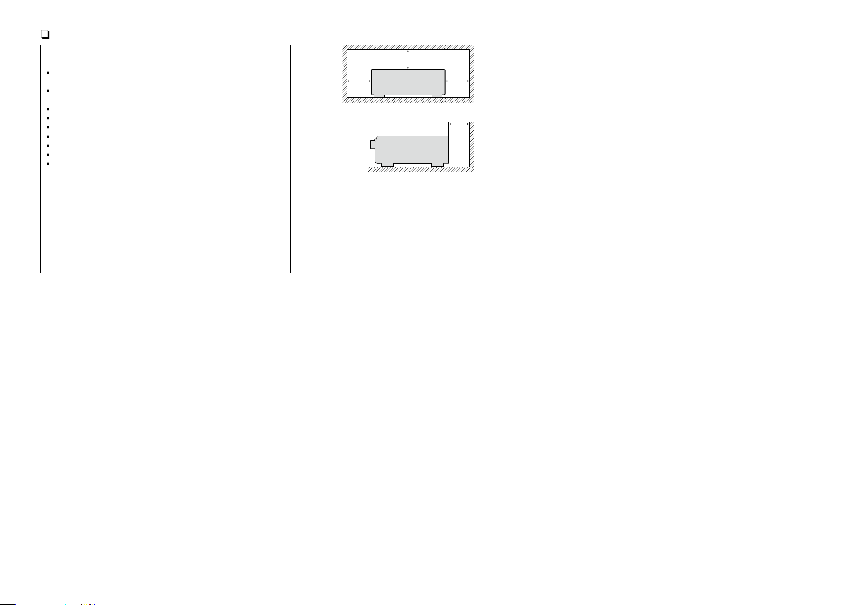
n CAUTIONS ON INSTALLATION
WARNINGS
•Avoid high temperatures.
Allow for sufficient heat dispersion when installed in a rack.
•Handle the power cord carefully.
Hold the plug when unplugging the cord.
•Keep the unit free from moisture, water, and dust.
•Unplug the power cord when not using the unit for long periods of time.
•Do not obstruct the ventilation holes.
•Do not let foreign objects into the unit.
•Do not let insecticides, benzene, and thinner come in contact with the unit.
•Never disassemble or modify the unit in any way.
•Ventilation should not be impeded by covering the ventilation openings
with items, such as newspapers, tablecloths or curtains.
•Naked flame sources such as lighted candles should not be placed on
the unit.
•Observe and follow local regulations regarding battery disposal.
•Do not expose the unit to dripping or splashing fluids.
•Do not place objects filled with liquids, such as vases, on the unit.
•Do not handle the mains cord with wet hands.
•When the switch is in the OFF (STANDBY) position, the equipment is not
completely switched off from MAINS.
•The equipment shall be installed near the power supply so that the power
supply is easily accessible.
z
z z
z
Wall
z For proper heat dispersal, do not install this unit in a confined
space, such as a bookcase or similar enclosure.
•More than 12 in. (0.3 m) is recommended.
•Do not place any other equipment on this unit.
II
Page 4
Getting started
Basic version
Advanced version
Information
Thank you for purchasing this DENON product. To ensure proper operation, please read this owner’s manual carefully before using the product.
After reading them, be sure to keep them for future reference.
Contents
Getting started ·············································································· 1
Accessories ··················································································1
Features ························································································ 2
Cautions on handling ····································································2
Basic version ············································································3
Connections ··················································································· 4
Important information ··································································· 4
Connecting an HDMI-compatible device ······································ 6
Connecting a TV············································································8
Connecting a Blu-ray Disc player/DVD player ······························· 9
Connecting a set-top box (Satellite tuner/Cable TV) ·····················9
Connecting a digital camcorder ··················································10
Connecting a control dock for iPod ············································· 10
Connecting an antenna ······························································· 11
Connecting a CD player ······························································ 11
Connecting an external control device ········································12
Settings ························································································ 13
Set up speakers (Audyssey® Auto Setup) ·································13
Playback (Basic operation) ························································· 20
Important information ································································· 20
Playing a Blu-ray Disc player/DVD player ···································· 21
Playing a CD player ····································································· 21
Playing an iPod® ········································································· 22
Tuning in radio stations ······························································· 25
Selecting a listening mode (Surround mode) ··························27
Selecting a listening mode··························································27
Advanced version ·······························································31
Speaker installation/connection (Advanced connection) ······· 32
Install ··························································································32
Connect ······················································································34
Set up speakers ·········································································· 39
Playback (Advanced operation) ················································· 41
Convenient functions ·································································· 41
Playback in ZONE2 (Separate room) ········································ 45
Audio output ··············································································· 45
Playback ······················································································ 45
Quick select function ·································································· 46
Sleep timer function ···································································46
How to make detailed settings ·················································· 47
Menu map ··················································································47
Examples of menu screen displays ············································ 48
Examples of menu and front display ··········································49
Inputting characters ··································································· 50
Audio Adjust ···············································································52
Information ·················································································58
System Setup ············································································· 59
Input Setup ················································································· 68
Operating the connected devices by remote control unit ······74
Operating AV devices ································································· 74
Registering preset codes ···························································· 75
Operating devices ······································································· 77
Specifying the zone used with the main remote control unit ····· 79
Resetting the remote control unit ···············································79
Information ·············································································80
Part names and functions···························································81
Front panel ·················································································· 81
Display ························································································ 82
Rear panel ··················································································· 83
Remote control unit ···································································· 84
Other information ·······································································86
Trademark information ································································86
Surround ····················································································· 87
Relationship between video signals and monitor output ············ 91
Explanation of terms ··································································· 92
Troubleshooting ·········································································· 94
Resetting the microprocessor ····················································96
Specifications ··············································································97
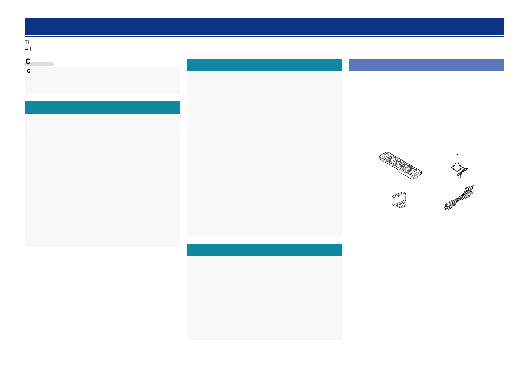
Accessories
Check that the following parts are supplied with the product.
q Getting Started ........................................................................ 1
w CD-ROM (Owner’s manual) .................................................... 1
e Warranty (for North America model only) ................................ 1
r Service network list ................................................................. 1
t Remote control unit (RC-1156) ................................................ 1
y R6/AA batteries ....................................................................... 2
u Setup microphone (DM-A409) ................................................. 1
i AM loop antenna ..................................................................... 1
o FM indoor antenna .................................................................. 1
t
i o
u
1
Page 5

Features
Basic version
Advanced version
Information
Cautions on handling
Fully discrete, identical quality and power for all
7 channels (125 W x 7ch)
The unit is equipped with a power amplifier that reproduces highfidelity sound in surround mode with equal quality and power for all
channels, true to the original sound.
The power amplifier circuit adopts a discrete-circuit configuration
that achieves high-quality surround sound reproduction.
Setup wizard, providing easy-to-follow setup
instructions
First select the language when prompted. Then simply follow the
instructions displayed on the TV screen to set up the speakers, etc.
Easy to use, Graphical User Interface
This unit is equipped with an easy to see “Graphical User Interface”
that uses menu displays and levels. The use of level displays
increases operability of the this unit.
Supports HDMI 1.4a with 3D, ARC, Deep Color,
“x.v.Color”, Auto Lip Sync and HDMI control
function (vpage6)
This unit can output 3D video signals input from a Blu-ray Disc
player to a TV that supports a 3D system. This unit also supports
the ARC (Audio Return Channel) function, which reproduces TV
sound with this unit via an HDMI cable used for connecting the
unit and a TVz.
z The TV should support the ARC function.
6-HDMI inputs and 1-output
The unit is equipped with 6 HDMI input connectors for connecting
devices with HDMI connectors, such as a Blu-ray Disc player,
game machine, HD video camera, etc.
High definition audio support
The unit is equipped with a decoder which supports high-quality
digital audio format for Blu-ray Disc players such as Dolby TrueHD,
DTS-HD Master Audio, etc.
•Before turning the power on
Check once again that all connections are correct and that there are
no problems with the connection cables.
•Power is supplied to some of the circuitry even when the unit is
set to the standby mode. When going on vacation or leaving home
for long periods of time, be sure to unplug the power cord from the
power outlet.
•About condensation
If there is a major difference in temperature between the inside of
the unit and the surroundings, condensation (dew) may form on
the operating parts inside the unit, causing the unit not to operate
properly.
If this happens, let the unit sit for an hour or two with the power
turned off and wait until there is little difference in temperature
before using the unit.
•Cautions on using mobile phones
Using a mobile phone near this unit may result in noise. If that
occurs, move the mobile phone away from this unit when it is in use.
•Moving the unit
Turn off the power and unplug the power cord from the power
outlet. Next, disconnect the connection cables to other system units
before moving the unit.
•About care
•Wipe the cabinet and control panel clean with a soft cloth.
•Follow the instructions when using a chemical cleaner.
•Benzene, paint thinner or other organic solvents as well as
insecticide may cause material changes and discoloration if brought
into contact with the unit, and should therefore not be used.
2
Page 6
Basic
Basic version
Advanced version
Information
Basic version
version
Basic version
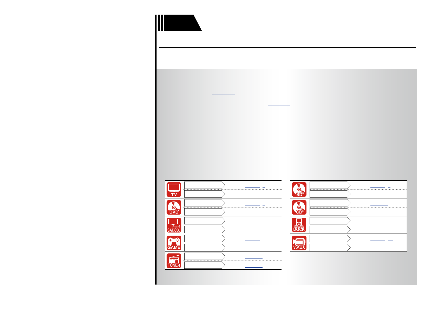
Here, we explain the connections and basic operation methods for this unit.
F Connections vpage4
F Settings vpage13
F Playback (Basic operation) vpage20
F Selecting a listening mode (Surround mode) vpage27
Connection
Playback
Connection
Playback
Connection
Playback
Connection
Playback
Connection
Playback
vpage7, 8
–
vpage7, 9
vpage21
vpage7, 9
–
vpage7
–
vpage11
vpage25
Connection
Playback
Connection
Playback
Connection
Playback
Connection
Playback
For speaker connections, see page34, C page 6 “Connecting the speakers”.
3
vpage7, 9
vpage21
vpage11
vpage21
vpage10
vpage22
vpage7, 10
–
Page 7
Connections
Basic version
Advanced version
Information
Basic version
vSee overleaf
Important information
•Make connections as follows before using this unit. Select an
appropriate connection type according to the devices to be
connected.
•You may need to make some settings on this unit depending
on the connection method. Refer to each description for more
information.
•Select the cables (sold separately) according to the devices
being connected.
NOTE
•Do not plug in the power cord until all connections have been
completed. (When the Setup wizard is running, follow the instructions
in the Setup wizard screen for making connections.)
•When running the Setup wizard, turn off the power supply of
connected devices.
•When making connections, also refer to the operating instructions of
the other devices being connected.
•Be sure to connect the left and right channels properly (left with left,
right with right).
•Do not bundle power cords together with connection cables. Doing
so can result in noise.
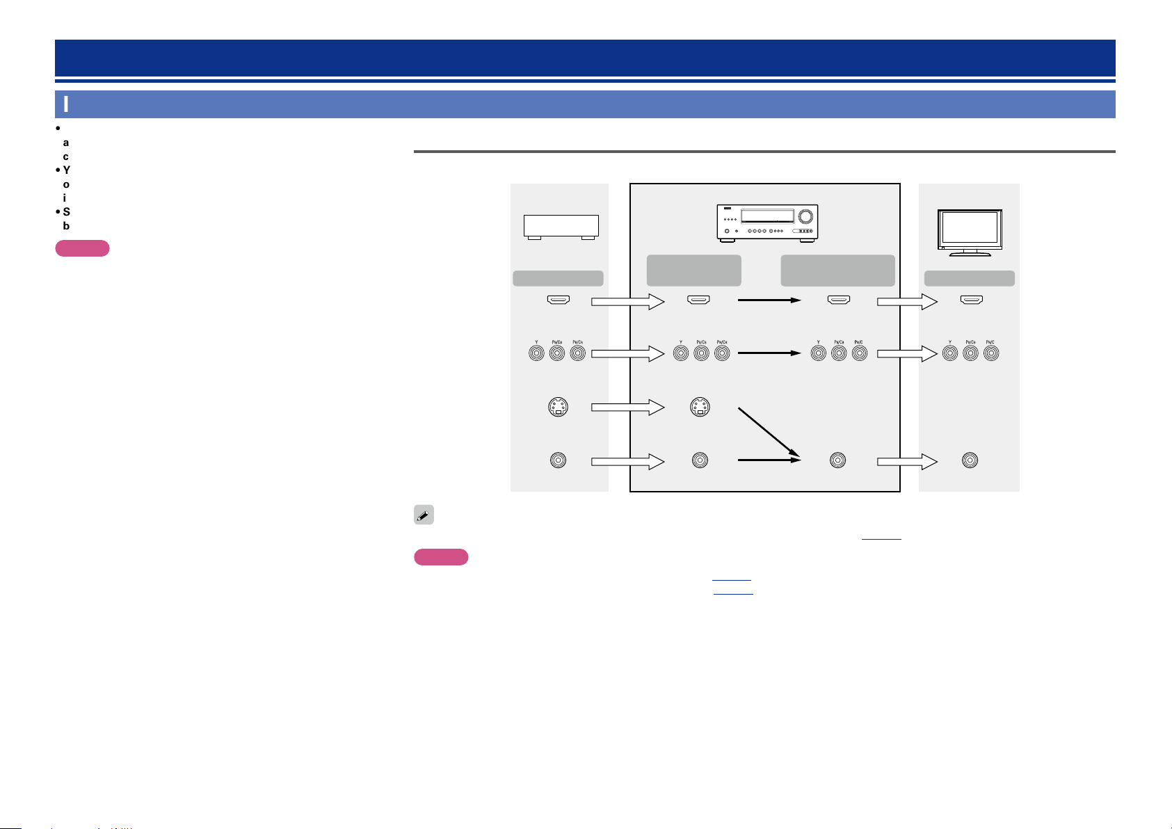
Relationship between video signals and monitor output
GFlow of video signals for MAIN ZONEH
Video device
Output
HDMI connector
Component video
connectors
S-Video connector
Input
(IN)
HDMI connector
Component video
connectors
S-Video
connector
This unit
Output
(MONITOR OUT)
HDMI
connector
Component video
connectors
Monitor (TV)
Input
HDMI connector
Component video
connectors
Video connector
Resolutions of HDMI-compatible TVs can be checked at “HDMI Monitor Information” (vpage58).
Video connector
Video connector
NOTE
•HDMI signals cannot be converted into analog signals (vpage91).
•Analog signals cannot be converted into HDMI signals (vpage91).
4
Video connector
Page 8
Important information
Basic version
Advanced version
Information
Basic version
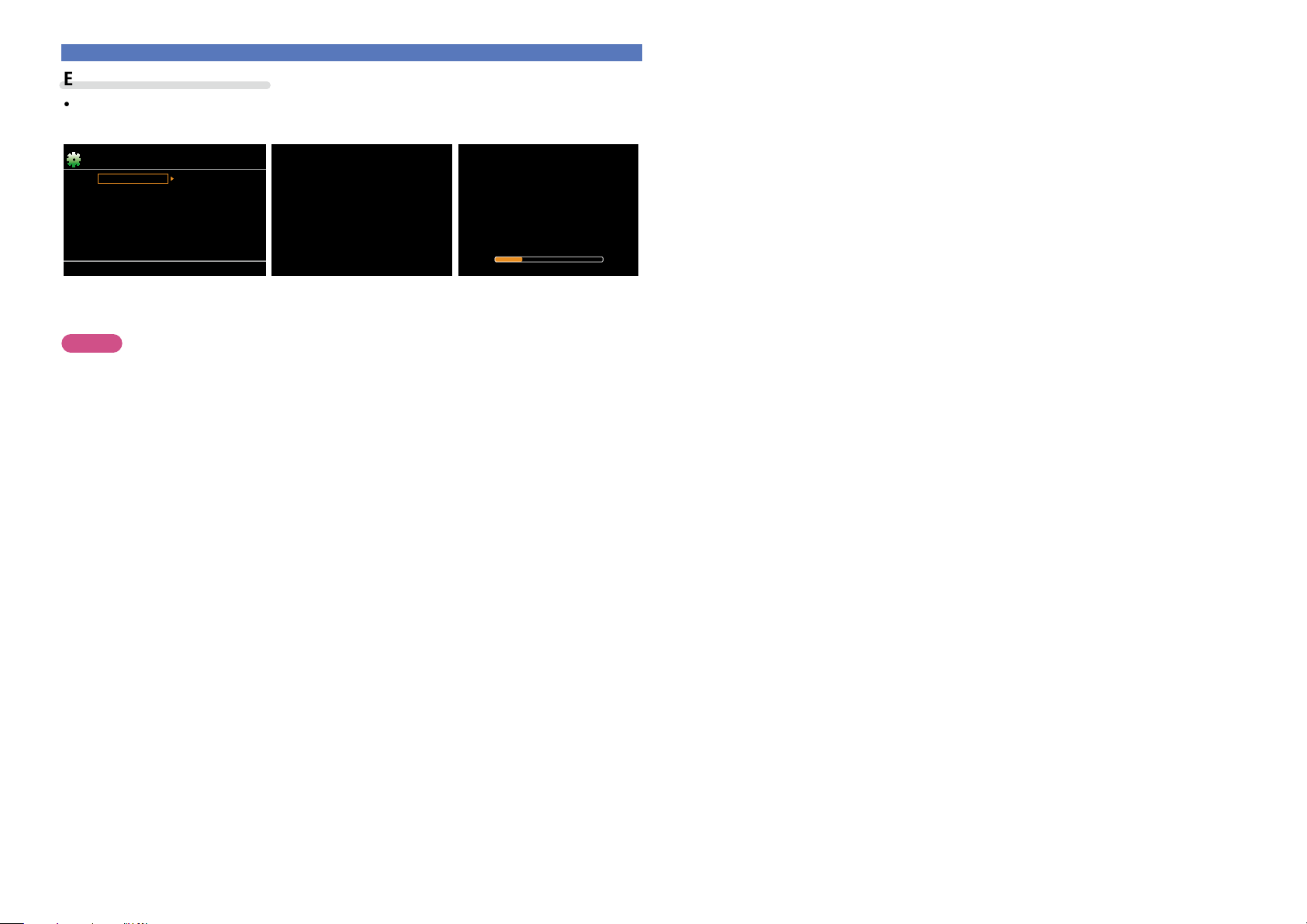
Examples of screen display
•Menu screen •Status display screen
When the input source is
switched.
Menu
Audio Adjust
Information
Setup Wizard
System Setup
Input Setup
Surr.Parameter
Tone
AudysseySettings
Manual EQ
RESTORER
Audio Delay
[Auto]
SOURCE :BD
MODE
:STEREO
Status display: The operating status appears briefly on the screen
when the input source is switched or the volume is
changed.
NOTE
•If you operate the menu while playing back 3D video content or computer’s resolution (e.g. VGA), the
playback video is replaced by the menu screen. The playback video is not displayed behind the menu
screen.
•This unit does not show the status display while playing back 3D video content or computer’s resolution
(e.g. VGA).
•The menu screen and status display are displayed when this unit and a TV are connected by HDMI.
Furthermore, the menu screen and status display are not displayed when this unit and a TV are connected
by VIDEO and COMPONENT VIDEO.
When the volume is adjusted.
Master Volume -55.5dB
5
Page 9
Connecting an HDMI-compatible device
Basic version
Advanced version
Information
Basic version
vSee overleaf
You can connect up to seven HDMI-compatible devices (6-inputs/1-output) to the unit.
HDMI function
This unit supports the following HDMI functions:
•3D
•Deep Color (vpage92)
•Auto Lip Sync (vpage63, 92)
•“x.v.Color”, sYCC601 color, Adobe RGB color, Adobe YCC601 color (vpage92, 93, 93)
•High definition digital audio format
•ARC (Audio Return Channel)
•Content Type
•CEC (HDMI control)
Copyright protection system
In order to play back digital video and audio such as BD-Video or DVD-Video via HDMI connection, both
this unit and TV or the player need to support the copyright protection system known as HDCP (Highbandwidth Digital Content Protection System). HDCP is copyright protection technology comprised of
data encryption and authentication of the connected AV devices. This unit supports HDCP.
•If a device that does not support HDCP is connected, video and audio are not output correctly. Read
the owner’s manual of your television or player for more information.
About HDMI cables
•When a device supporting Deep Color is connected, use a cable compatible with “High Speed HDMI
cable” or “High Speed HDMI cable with Ethernet”.
•When the ARC function is used, connect a device with a ”Standard HDMI cable with Ethernet” or “High
Speed HDMI cable with Ethernet” for HDMI 1.4a.
HDMI control function (vpage41)
This function allows you to operate external devices from the unit and operate the unit from external
devices.
NOTE
•The HDMI control function may not work depending on the device it is connected to and its settings.
•You cannot operate a TV or Blu-ray Disc player/DVD player that is not compatible with the HDMI control
function.
About 3D function
This unit supports input and output of 3D (3 dimensional) video signals of HDMI 1.4a.
To play back 3D video, you need a TV and player that provide support for the HDMI1.4a 3D function and
a pair of 3D glasses.
NOTE
•When playing back 3D video, refer to the instructions provided in the manual of your playback device
together with this manual.
•If you operate the menu while playing back 3D video content, the playback video is replaced by the menu
screen. The playback video is not displayed behind the menu screen.
•This unit does not show the status display while playing back 3D video content.
•If 3D video with no 3D information is input, the menu screen and status display on this unit are displayed
over the playback video.
•If 2D video is converted to 3D video on the television, the menu screen and status display on this unit
are not displayed correctly. To view the menu screen and status display on this unit correctly, turn the
television setting that converts 2D video to 3D video off.
About ARC (Audio Return Channel) function
The Audio Return Channel in HDMI 1.4a enables a TV, via a single HDMI cable, to send audio data “upstream”
to this unit.
NOTE
•To enable the ARC function, set “HDMI Control” to “ON” (vpage63).
•When connecting a TV that does not support the ARC function, a separate connection using an audio
cable is required. In this case, refer to “Connecting a TV” (vpage8) for the connection method.
About Content Type
HDMI 1.4a enables simple, automated picture setting selection with no user intervention.
NOTE
To enable the Content Type, set “Video Mode” to “Auto” (vpage71).
6
Page 10
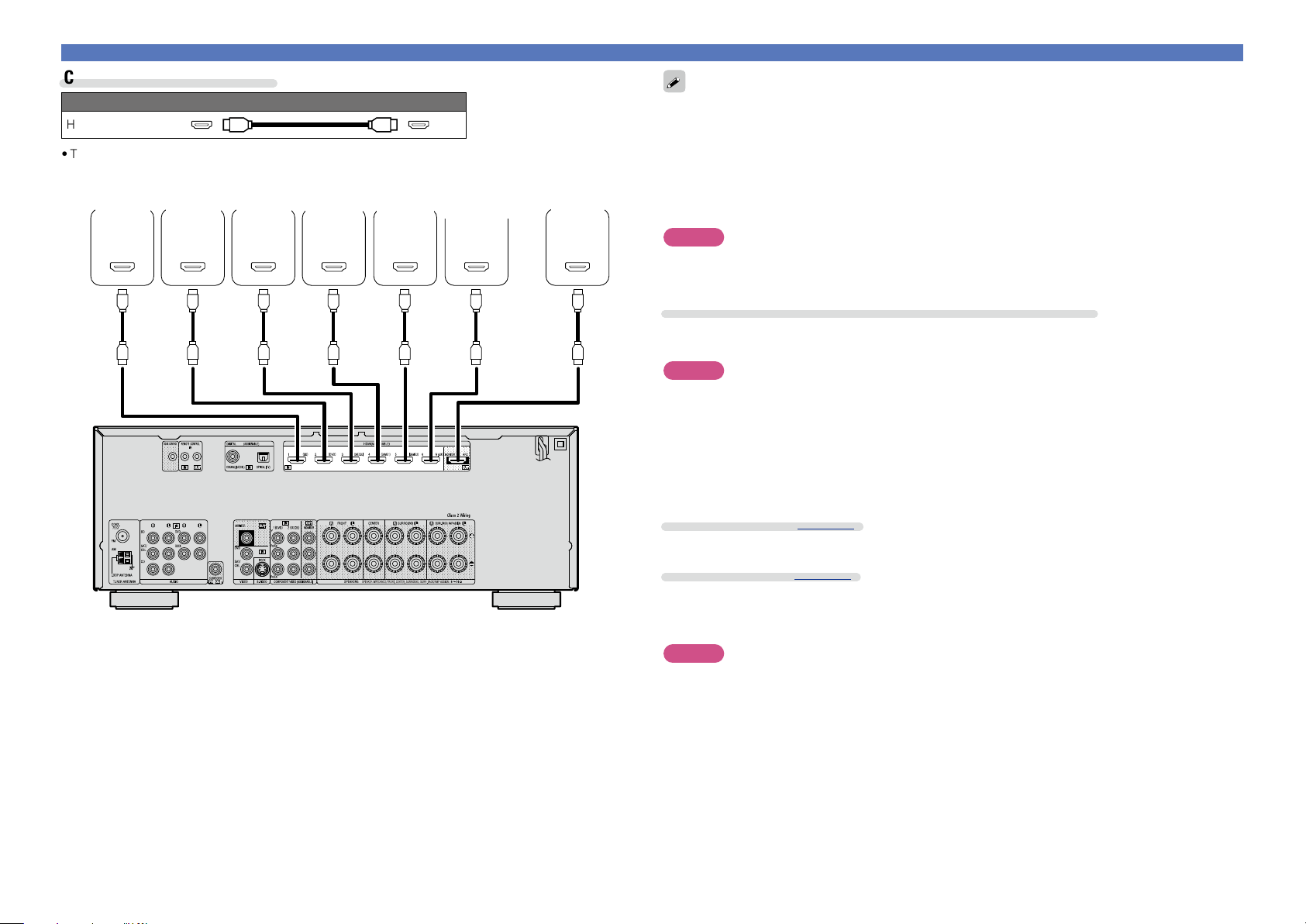
Cables used for connections
Basic version
Advanced version
Information
Basic version
Audio and video cable (sold separately)
HDMI cable
•This interface allows transfer of digital video signals and digital audio signals over a single HDMI cable.
Blu-ray
Disc
player
HDMI
OUT
DVD
player
HDMI
OUT
Set-top
box
HDMI
OUT
Game
console 1
HDMI
OUT
Game
console 2
HDMI
OUT
Digital
camcorder
HDMI
OUT
TV
HDMI
IN
Connecting an HDMI-compatible device
•When this unit is connected to other devices with HDMI cables, connect this unit and TV also with an
HDMI cable.
•When connecting a device that supports Deep Color, please use a “High Speed HDMI cable” or “High
Speed HDMI cable with Ethernet”.
•Video signals are not output if the input video signals do not match the monitor’s resolution. In this case,
switch the Blu-ray Disc/DVD player’s resolution to a resolution with which the monitor is compatible.
•When this unit and monitor are connected with an HDMI cable, if the monitor is not compatible with
HDMI audio signal playback, only the video signals are output to the monitor.
NOTE
The audio signal from the HDMI output connector (sampling frequency, number of channels, etc.) may be
limited by the HDMI audio specifications of the connected device regarding permissible inputs.
Connecting to a device equipped with a DVI-D connector
When an HDMI/DVI conversion cable (sold separately) is used, the HDMI video signals are converted to
DVI signals, allowing connection to a device equipped with a DVI-D connector.
NOTE
•No sound is output when connected to a device equipped with a DVI-D connector. Make separate audio
connections.
•Signals cannot be output to DVI-D devices that do not support HDCP.
•Depending on the combination of devices, the video signals may not be output.
nSettings related to HDMI connections
Set as necessary. For details, see the respective reference pages.
Input Assign (vpage70)
Set this to change the HDMI input connector to which the input source is assigned.
HDMI Setup (vpage63)
Make settings for HDMI video/audio output.
•Auto Lip Sync •HDMI Audio Out •HDMI Control
•Standby Source •P.Off Control
NOTE
The audio signal input from the HDMI input connector can be output as an output signal from the HDMI
output connector by setting the HDMI audio output destination to TV.
Audio signals input via the Analog/Coaxial/Optical input connectors cannot be output from the HDMI
output connector.
7
Page 11
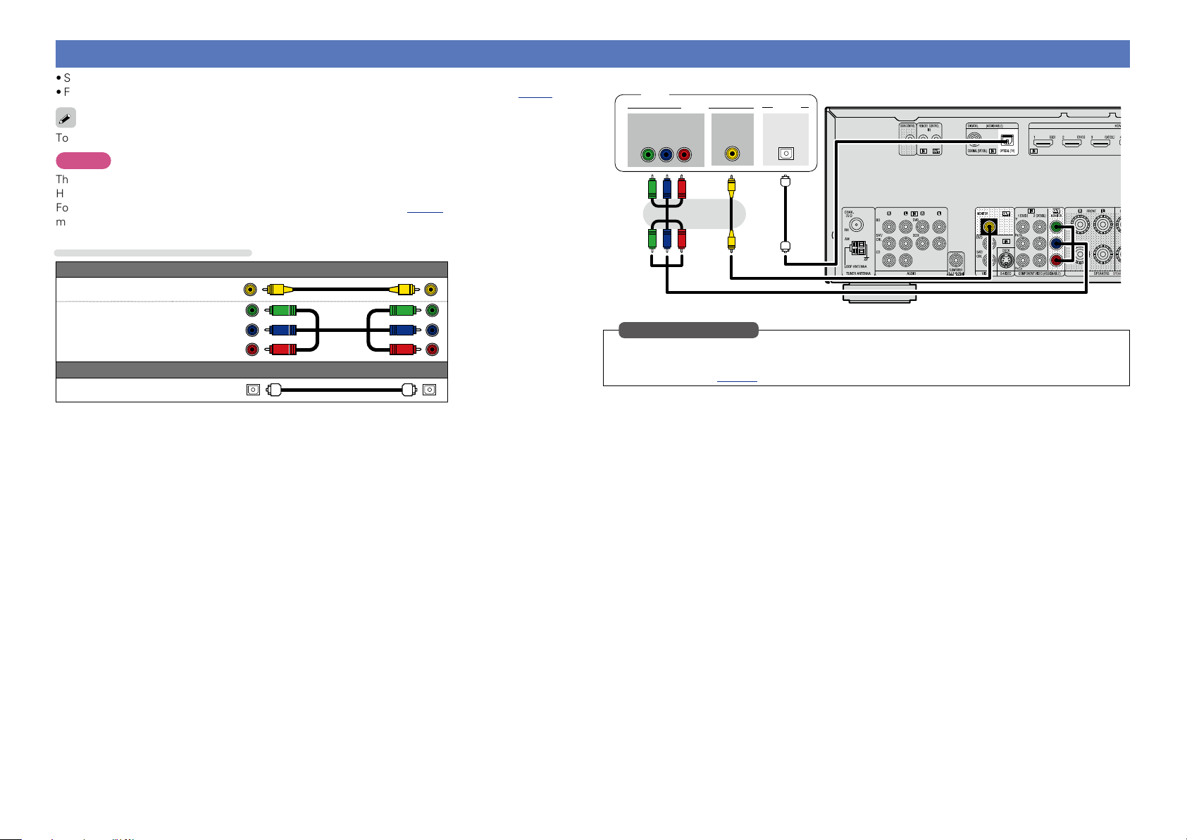
Connecting a TV
Basic version
Advanced version
Information
Basic version
•Select the connector to use and connect the device.
•For instructions on HDMI connections, see “Connecting an HDMI-compatible device” (vpage6).
To listen to TV audio through this device, use the optical digital connection.
NOTE
The optical connection is not required when a TV compatible with the ARC function (Audio Return Channel
HDMI 1.4a standard function) is connected to this unit via an HDMI connection.
For details, see “About ARC (Audio Return Channel) function” (vpage 6) or refer to the instruction
manual for your TV.
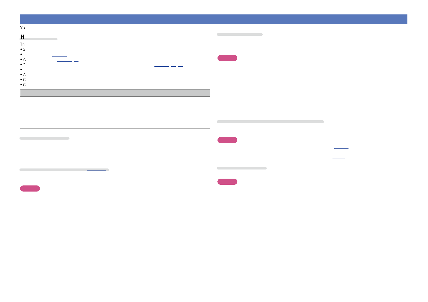
Cables used for connections
Video cable (sold separately)
Video cable
TV
Y P
IN
B PR
VIDEO
COMPONENT VIDEO
VIDEO
IN
AUDIO
OPTICAL
OUT
Component video
cable
Optical cable
Audio cable (sold separately)
in Set as Necessary
Set this to change the digital input connector or component video input connector to which the input
source is assigned.
“Input Assign” (vpage70)
8
Page 12
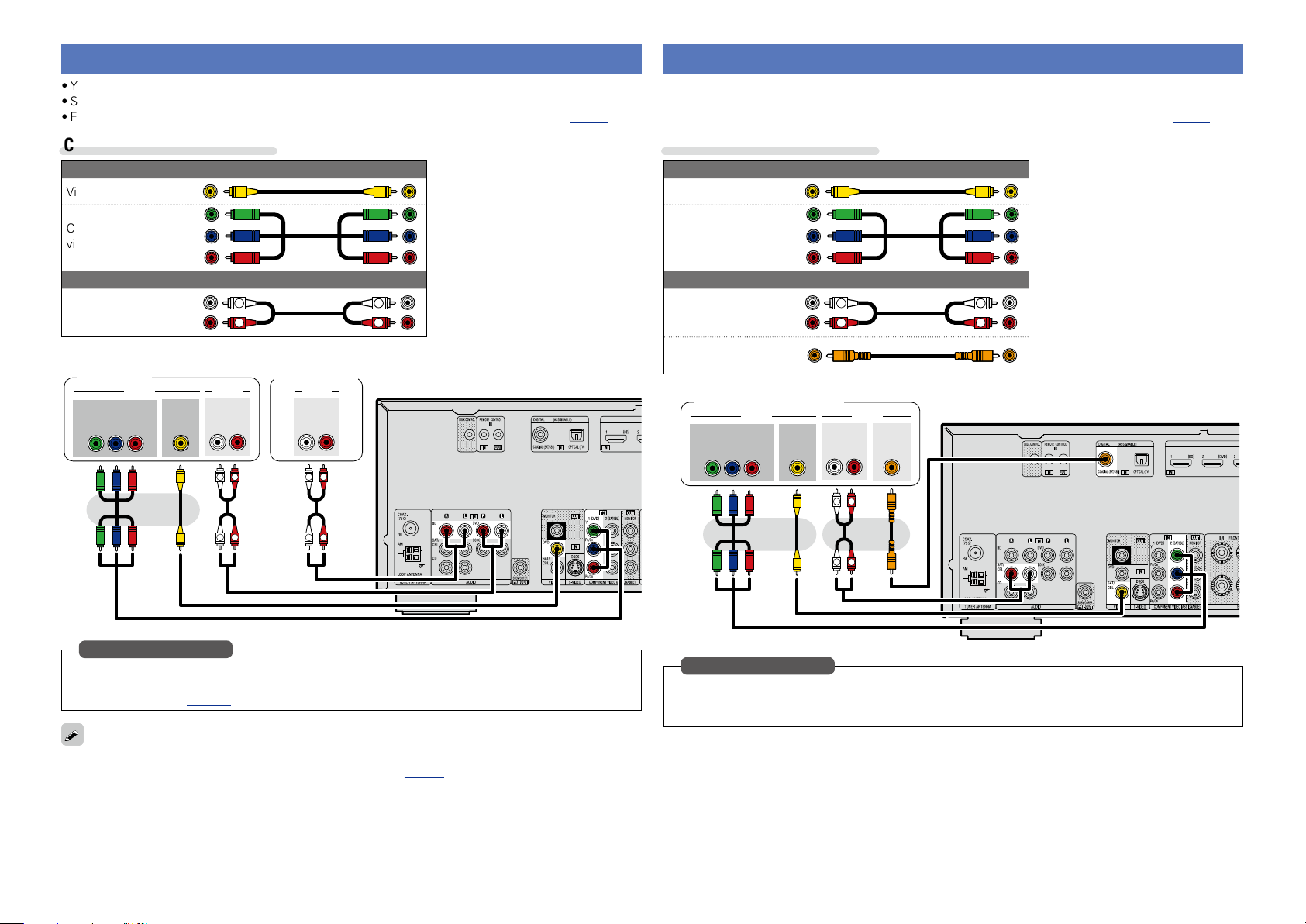
Connecting a Blu-ray Disc player/DVD player
Basic version
Advanced version
Information
Basic version
•You can enjoy video and audio from a Blu-ray Disc or DVD.
•Select the connector to use and connect the device.
•For instructions on HDMI connections, see “Connecting an HDMI-compatible device” (vpage6).
Connecting a set-top box (Satellite tuner/Cable TV)
•You can watch satellite or cable TV.
•Select the connector to use and connect the device.
•For instructions on HDMI connections, see “Connecting an HDMI-compatible device” (vpage6).
Cables used for connections
Video cable (sold separately)
Video cable
Component
video cable
Audio cable (sold separately)
AUDIO
OUT
L
L
L
R
RL
R
R
Audio cable
DVD player
COMPONENT VIDEO
OUT
B PR
Y P
VIDEO AUDIO
VIDEO
OUT
Blu-ray Disc
player
AUDIO
AUDIO
OUT
RL
R
L
R
L
Cables used for connections
Video cable (sold separately)
Video cable
Component
video cable
Audio cable (sold separately)
L
R
Audio cable
L
R
Coaxial
digital cable
Satellite tuner/Cable TV
COMPONENT VIDEO
VIDEO AUDIO
OUT
B PR
Y P
VIDEO
OUT
AUDIO
OUT
L
L
COAXIAL
OUT
RL
R
R
L
R
in Set as Necessary
Set this to change the digital input connector or component video input connector to which the input
source is assigned.
“Input Assign” (vpage70)
When you want to play back HD Audio (Dolby TrueHD, DTS-HD, Dolby Digital Plus, DTS Express) and Multichannel PCM with this unit, use an HDMI connection (vpage 6 “Connecting an HDMI-compatible
device”).
in Set as Necessary
Set this to change the digital input connector or component video input connector to which the input
source is assigned.
“Input Assign” (vpage70)
9
Page 13
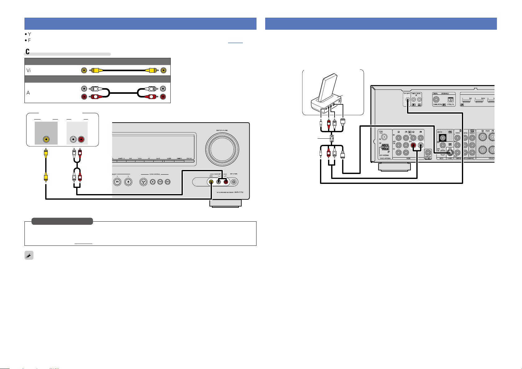
Connecting a digital camcorder
Basic version
Advanced version
Information
Basic version
•You can enjoy video and audio from a digital camcorder.
•For instructions on HDMI connections, see “Connecting an HDMI-compatible device” (vpage6).
Cables used for connections
Video cable (sold separately)
Video cable
Audio cable (sold separately)
Audio cable
L
R
L
R
Connecting a control dock for iPod
•Connect a control dock for iPod to the unit to enjoy video and music stored on an iPod.
•For a control dock for iPod, use ASD-1R, ASD-11R, ASD-3N, ASD-3W, ASD-51N or ASD-51W made by
DENON (sold separately).
•For instructions on the control dock for iPod settings, refer to the control dock for iPod’s operating
instructions.
Control dock for iPod
ASD-11R
Digital camcorder
AUDIOVIDEO
VIDEO
OUT
AUDIO
OUT
L
L
RL
R
R
in Set as Necessary
Set this to change the digital input connector or component video input connector to which the input
source is assigned.
“Input Assign” (vpage70)
You can enjoy games by connecting a game machine via the V.AUX input connector. In this case, select
the input source to “V.AUX”.
Use the AV/Control
Cable supplied with
the DENON control
dock for iPod.
R
L
R
L
10
Page 14
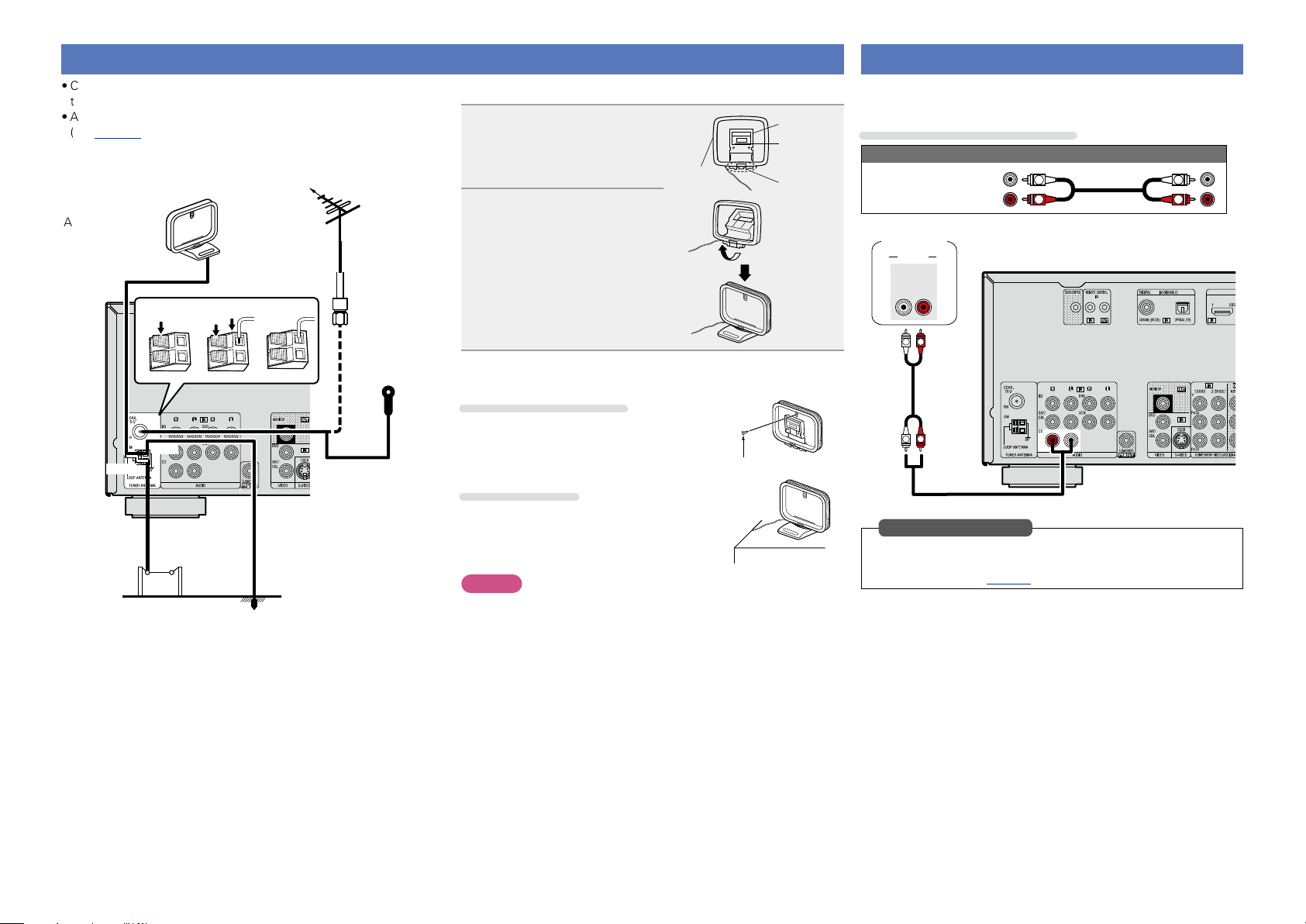
Connecting an antenna
Basic version
Advanced version
Information
Basic version
•Connect the FM antenna or AM loop antenna supplied with the unit
to enjoy listening to radio broadcasts.
•After connecting the antenna and receiving a broadcast signal
(vpage 25 “Listening to FM/AM broadcasts”), fix the antenna
with tape in a position where the noise level becomes minimal.
Direction of broadcasting station
FM outdoor
AM loop antenna
(supplied)
White
AM outdoor
antenna
w eq
Black
Ground
antenna
75 Ω coaxial
cable
FM indoor
antenna
(supplied)
nAM loop antenna assembly
Put the stand section
1
through the bottom of the
loop antenna from the
rear and bend it forward.
Insert the projecting part
2
into the square hole in
the stand.
Loop
antenna
Stand
Square
hole
Projecting
part
nUsing the AM loop antenna
Suspending on a wall
Suspend directly on a wall without assembling.
Nail, tack, etc.
Standing alone
Use the procedure shown above to assemble.
NOTE
•Do not connect two FM antennas simultaneously.
•Even if an external AM antenna is used, do not disconnect the AM
loop antenna.
•Make sure the AM loop antenna lead terminals do not touch metal
parts of the panel.
•If the signal has noise interference, connect the ground terminal
(GND) to reduce noise.
•If you are unable to receive a good broadcast signal, we recommend
installing an outdoor antenna. For details, inquire at the retail store
where you purchased the unit.
Connecting a CD player
•You can enjoy CD sound.
•Select the connector to use and connect the device.
Cables used for connections
Audio cable (sold separately)
Audio cable
CD player
AUDIO
AUDIO
OUT
L
L
RL
R
R
L
R
in Set as Necessary
Set this to change the digital input connector to which the input
source is assigned.
“Input Assign” (vpage70)
L
R
11
Page 15
Connecting an external control device
Basic version
Advanced version
Information
Basic version
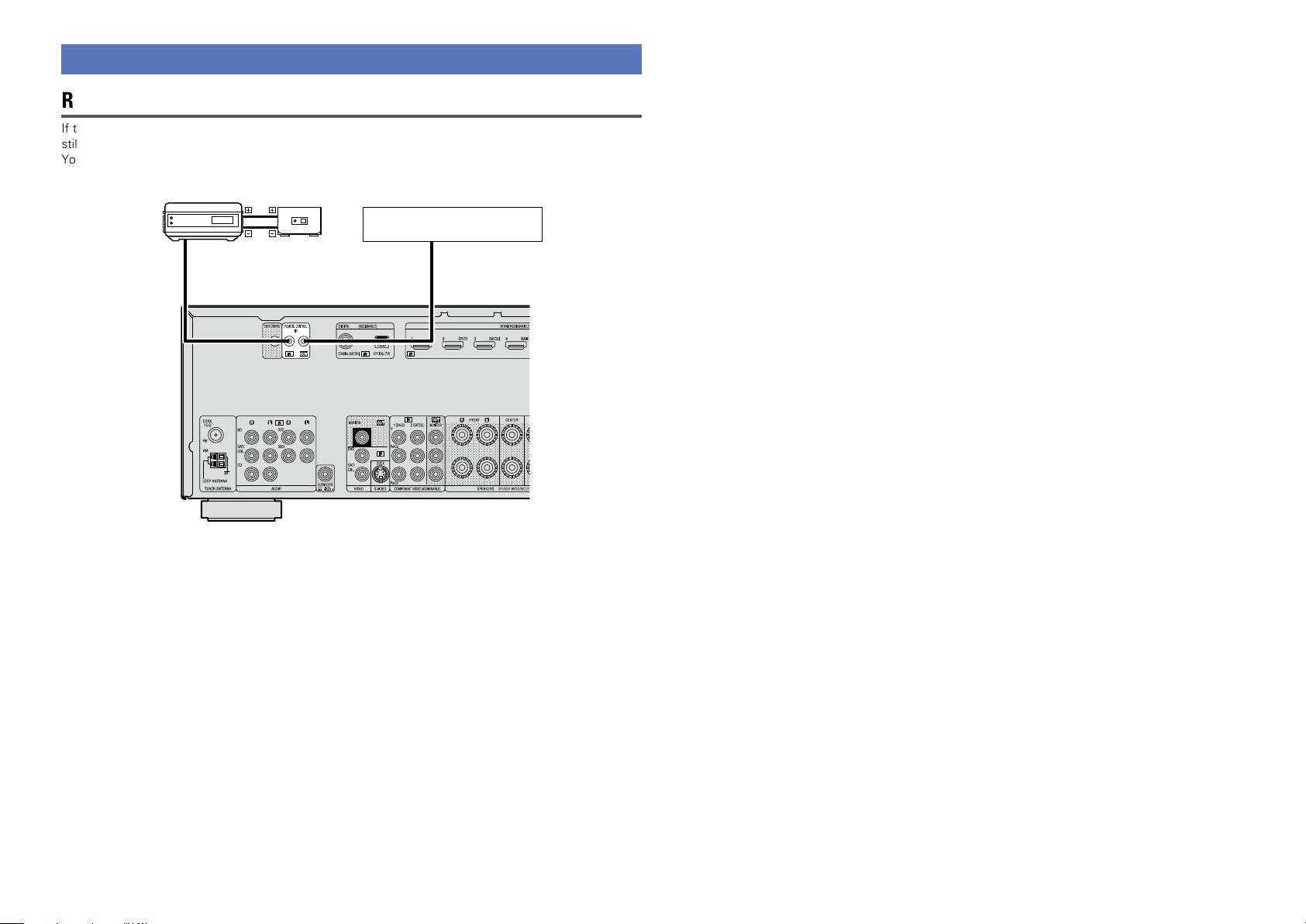
REMOTE CONTROL jacks
If this unit is installed in a location that is out of range of the signal from the remote control unit, you can
still operate the unit and the devices connected to it by using a commercially available IR receiver.
You can also use it to remotely control ZONE2 (another room).
retransmitter
AUX
OUT
Infrared
Input
Infrared
sensor
Device equipped with a
REMOTE CONTROL IN jack
Output
12
Page 16
Settings
Basic version
Advanced version
Information
Basic version
vSee overleaf
Here, we explain “Audyssey® Auto Setup”, which allows you to
automatically make the optimal settings for your speakers.
Set up speakers (Audyssey® Auto Setup)
n Set up speakers (Audyssey® Auto Setup)
(vpage13)
Playback (Basic operation) (vpage20)
Selecting a listening mode (Surround mode)
(vpage27)
Playback (Advanced operation) (vpage41)
The acoustic characteristics of the connected speakers and
listening room are measured and the optimum settings are made
automatically. This is called “Audyssey® Auto Setup”.
To perform measurement, place the setup microphone in
multiple locations all around the listening area. For best results,
we recommend you measure in six or more positions, as shown
in the illustration (up to eight positions).
•When performing Audyssey® Auto Setup, Audyssey MultEQ® XT/
Audyssey Dynamic EQ®/Audyssey Dynamic Volume® functions
become active (vpage55, 56).
•To set up the speakers manually, use “Speaker Setup”
(vpage60) on the menu.
NOTE
•Make the room as quiet as possible. Background noise can disrupt
the room measurements. Close windows, silence cell phones,
televisions, radios, air conditioners, fluorescent lights, home
appliances, light dimmers, or other devices as measurements may
be affected by these sounds.
•Cell phones should be placed away from all audio electronics during
the measurement process as Radio Frequency Interference (RFI)
may cause measurement disruptions (even if the cell phone is not
in use).
•Do not unplug the setup microphone from the main unit until
Audyssey® Auto Setup is completed.
•Do not stand between the speakers and setup microphone or allow
obstacles in the path while the measurements are being made. This
will cause inaccurate readings.
•Loud test sounds may be played during Audyssey® Auto setup. This
is part of normal operation. If there is background noise in room,
these test signals will increase in volume.
•Operating
will cancel the measurements.
•Measurement cannot be performed when
headphones are connected.
M df during the measurements
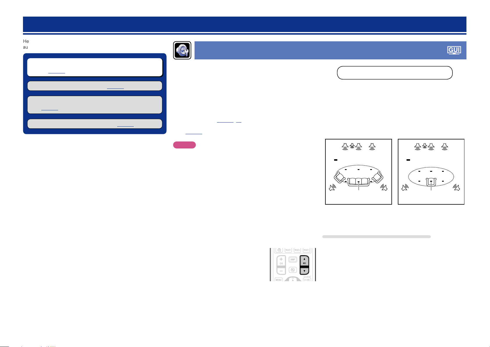
About setup microphone placement
•Measurements are performed by placing the setup microphone
successively at multiple positions throughout the entire listening
area, as shown in GExample qH. For best results, we recommend
you measure in six or more positions, as shown in the illustration
(up to eight positions).
•Even if the listening environment is small as shown in GExample wH,
measuring at multiple points throughout the listening environment
results in more effective correction.
GExample qH GExample wH
FL SW C FR
( : Measuring positions)
M
*
FL Front speaker (L) SW Subwoofer
FR Front speaker (R) SL Surround speaker (L)
C Center speaker SR Surround speaker (R)
SRSL
FL SW C FR
( : Measuring positions)
M
*
SRSL
About the main listening position (*M)
The main listening position is the position where listeners would
normally sit or where one would normally sit alone within the listening
environment. Before starting Audyssey® Auto Setup, place the setup
microphone in the main listening position. Audyssey MultEQ® XT uses
the measurements from this position to calculate speaker distance,
level, polarity, and the optimum crossover value for the subwoofer.
13
Page 17
Set up speakers (Audyssey® Auto Setup)
Basic version
Advanced version
Information
Basic version
vSee overleaf
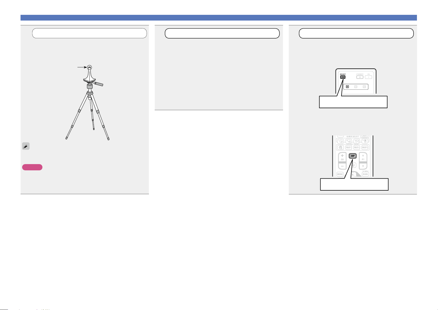
1
Mount the setup microphone on a tripod or stand
and place it in the main listening position.
When placing the setup microphone, adjust the height of the
sound receptor to the level of the listener’s ear.
If you do not have a tripod or stand, set up the microphone on, for
example, a seat without a back.
NOTE
•Do not hold the setup microphone in your hand during
measurements.
•Avoid placing the setup microphone close to a seat back or wall as
sound reflections may give inaccurate results.
Set up the microphone
Sound receptor
Setup
microphone
2
If using a subwoofer capable of the following
adjustments, set up the subwoofer as shown below.
n When using a subwoofer with a direct mode
Set the direct mode to “On” and disable the volume adjustment
and crossover frequency setting.
n When using a subwoofer without a direct mode
Make the following settings:
•Volume : “12 o’clock position”
•Crossover frequency : “Maximum/Highest Frequency”
•Low pass filter : “Off”
•Standby mode : “Off”
Set up the subwoofer
3
Press ZONE SELECT to switch the zone mode to
Set up the remote control unit
n Set up the zone mode
J (MAIN ZONE).
The J indicator lights.
Press ZONE SELECT
n Set up the operation mode
Press AMP to set the remote control unit to AMPoperation mode.
Press AMP
14
Page 18

Set up speakers (Audyssey® Auto Setup)
Basic version
Advanced version
Information
Basic version
vSee overleaf
STEP 1
Preparation
Connect the setup microphone to the SETUP MIC
4
jack of this unit.
When the setup microphone is
connected, the following screen is
displayed.
Audyssey Auto Setup
Preparation
Connect the speakers and place then according
to the recommendations in the manual.
Next
MultEQ XT
[RETURN][ENTER] Enter Cancel
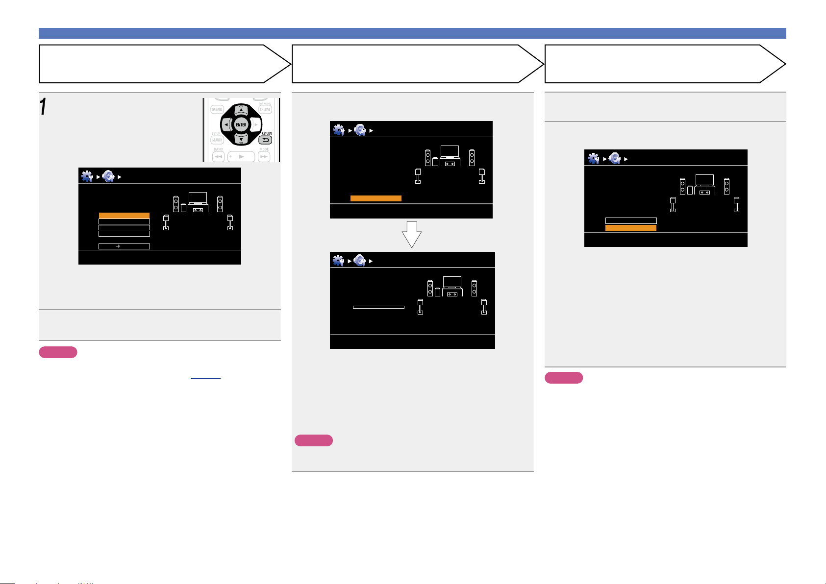
Use ui to select “Auto Setup Start” and then press
6
ENTER.
Audyssey Auto Setup MultEQ XT
Preparation
Set the following items
if necessary.
Amp Assign
Channel Select
Auto Setup Start
[RETURN][ENTER] Enter Cancel
Here, we explain setup using the example of 5.1-channel speaker
playback.
For settings other than 5.1-channel surround, select “Amp Assign”
and perform step 4 to 5 of “Set up “Amp Assign”” (vpage39).
If unused channels are set with “Channel Select”, measuring time
can be shortened. For setting, perform steps 7 to 11 of “Set up
“Channel Select”” (vpage40).
STEP 2
Detect & Measure (Main)
•In STEP 2, you will perform measurements at the main listening
position.
•This step automatically checks the speaker configuration and speaker
size, and calculates the channel level, distance, and crossover
frequency.
It also corrects distortion in the listening area.
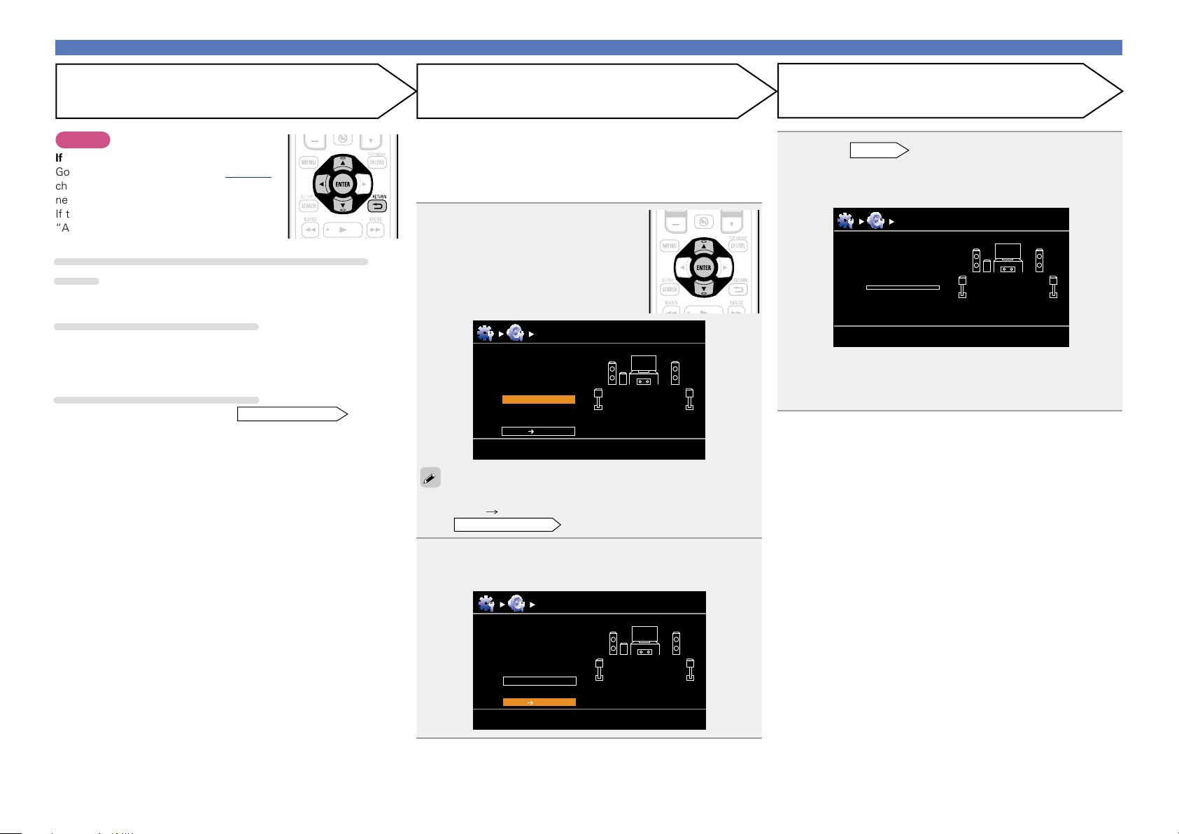
Select “Measure” and then press ENTER.
7
When measuring begins, a test tone is output from each
speaker.
•Measurement requires several minutes.
The detected speakers are displayed.
8
•The illustration below shows an example of when the front
speakers, center speaker, subwoofer, and surround speakers have
been detected.
Audyssey Auto Setup MultEQ XT
Detect Check
Front
Center
Subwoofer
Surround
Yes
Yes
Yes
Yes
5
Select “Next” and then press
ENTER.
15
Retry
Next Measure
[ENTER] Enter
[RETURN] Cancel
NOTE
If a connected speaker is not displayed, the speaker may not be
connected correctly. Check the speaker connection.
Use ui to select “Next → Measure” and then press
9
ENTER.
Page 19
Set up speakers (Audyssey® Auto Setup)
Basic version
Advanced version
Information
Basic version
vSee overleaf
STEP 2 (Continued)
Detect & Measure (Main)
NOTE
If “Caution” is displayed:
Go to “Error messages” (vpage 18),
check any related items, and perform the
necessary procedures.
If the problem is resolved, return and restart
“Audyssey® Auto Setup”.
When performing Audyssey® Auto Setup over
again
Press ui to select “Retry”, and then press ENTER.
When measuring has stopped
q Press RETURN B, to the “Cancel Auto Setup?” prompt is
displayed.
w Press o to select “Yes”, then press ENTER.
Setting up the speakers again
Repeat the operation from step 4 of
STEP 1 Preparation
.
STEP 3
Measure (2nd – 8th)
•In STEP 3, you will perform measurements at multiple positions (two
to eight positions) other than the main listening position.
•Just one position can be measured but measuring multiple positions
increases the accuracy of the correction of acoustic distortion within
the listening area.
Move the setup microphone to
10
position 2, use ui to select
“Measure”, and then press
ENTER.
The measurement of the second
position starts. Measurements can be
made in up to eight positions.
Audyssey Auto Setup MultEQ XT
Measure (2nd)
Please place the
microphone at ear
height at 2nd
listening position.
Measure
Next Calculate
[RETURN][ENTER] Enter Cancel
STEP 4
Calculate
On the
12
Calculate”, and then press ENTER.
Measuring results are analyzed, and the frequency response of
each speaker in the listening room is determined.
•Analysis takes several minutes to complete. The time required for
this analysis depends on the number of speakers connected.
The more connected speakers there are, the longer it takes to
perform analysis.
STEP 3
Calculate
Now calculating
Please wait
0%
screen, use ui to select “Next →
Audyssey Auto Setup MultEQ XT
If you want to omit measurements from the next position onward,
select “Next Calculate”.
(Go to
STEP4 Calculate
)
Repeat step 10, measuring positions 3 to 8.
When measurement of position 8 is completed, a
11
“Measurements finished.” message is displayed.
Audyssey Auto Setup MultEQ XT
Measure (Finish)
Measurements finished.
Retry
Next Calculate
[RETURN][ENTER] Enter Cancel
16
Page 20
Set up speakers (Audyssey® Auto Setup)
Basic version
Advanced version
Information
Basic version
STEP 5
Check
Use ui to select the item you
13
want to check, and then press
ENTER.
Audyssey Auto Setup
Check
Check processing resuit.
To proceed, press
“Next”.
Sp.Config. Check
Distance Check
Ch.Level Check
Crossover Check
Next Store
•Subwoofers may measure a greater reported distance than
the actual distance due to added electrical delay common in
subwoofers.
•If you want to check another item, press RETURN B.
Use ui to select “Next → Store” and then press
14
ENTER.
NOTE
•If the result differs from the actual connection status, or if “Caution!”
is displayed, see “Error messages” (vpage 18). Then carry out
Audyssey® Auto Setup again.
• If you change speaker positions or orientation, perform Audyssey®
Auto Setup again to find the optimal equalizer settings.
MultEQ XT
[RETURN][ENTER] Enter Cancel
STEP 6
Store
Select “Store” and then press ENTER.
15
Save the measurement results.
Audyssey Auto Setup MultEQ XT
Store
Press “Store” to
store calculation
result.
Store
[RETURN][ENTER] Enter Cancel
Audyssey Auto Setup MultEQ XT
Store
Now storing
Please wait
0%
•Saving the results requires about 10 seconds.
•If the measuring results are not to be saved, press RETURN B.
A message “Cancel Auto Setup?” will be displayed. Press o then
select “Yes”. All the measured Audyssey® Auto Setup data will
be erased.
•During saving of measurements results, “Now storing Please
wait...” is displayed. When saving is completed, “Storing complete.
Auto Setup is now finished.” is displayed.
NOTE
During saving of measurement results, be sure not to turn off the
power.
Finish
Unplug the setup microphone from the unit’s SETUP
16
MIC jack.
Set Audyssey Dynamic Volume®.
17
Audyssey Auto Setup MultEQ XT
Finish
Storing complete.
Auto Setup is now finished.
Please unplug microphone.
Turn on Dynamic Volume?
Yes
No
[ENTER] Exit
•This feature adjusts the output volume to the optimal level while
constantly monitoring the level of the audio input to the unit.
Optimal volume control is performed automatically without any
loss in the dynamism and clarity of the sound when, for example,
the volume suddenly increases for commercials shown during
television programs.
n When turning Dynamic Volume® on
•Use u to select “Yes”, and then press ENTER.
The unit automatically enters “Evening” mode.
n When turning Dynamic Volume® off
•Use i to select “No”, and then press ENTER.
NOTE
After performing Audyssey® Auto Setup, do not change the speaker
connections or subwoofer volume. In event of a change, perform
Audyssey® Auto Setup again.
17
Page 21
Set up speakers (Audyssey® Auto Setup)
Basic version
Advanced version
Information
Basic version
Error messages
NOTE
•An error message is displayed if Audyssey® Auto Setup could not be completed due to speaker placement, the measurement environment, etc. If this happens, check the relevant items, be sure to take the necessary
measures, then perform Audyssey® Auto Setup over again.
•If the result still differs from the actual connection status after remeasurement or the error message still appears, it is possible that the speakers are not connected properly. Turn this unit off, check the speaker
connections and repeat the measurement process from the beginning.
•Be sure to turn off the power before checking speaker connections.
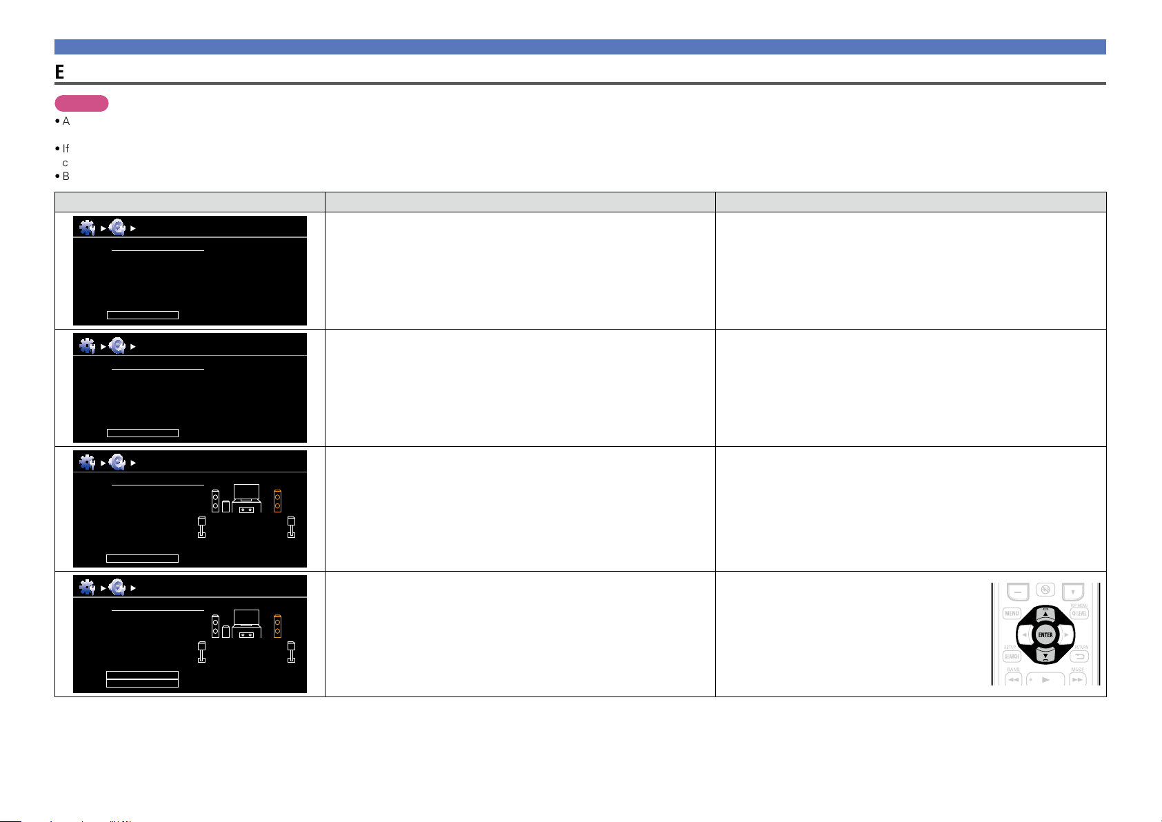
Examples Error details Measures
Audyssey Auto Setup
Caution!
Microphone or Speaker is none
Retry
MultEQ XT
•The connected setup microphone is broken, or a device other than the
supplied setup microphone is connected.
•Not all speakers could be detected.
•The front L speaker was not properly detected.
•Connect the included setup microphone to the SETUP MIC jack of this unit.
•Check the speaker connections.
Audyssey Auto Setup
Caution!
Ambient noise is too high or level is too low
Retry
Audyssey Auto Setup
Caution! Speaker:None
Front R
Retry
Audyssey Auto Setup
Caution! Speaker:Phase
Front R
Skip
Retry
MultEQ XT
MultEQ XT
MultEQ XT
•There is too much noise in the room for accurate measurements to be
made.
•Speaker or subwoofer sound is too low for accurate measurements to be
made.
•The displayed speaker could not be detected.
(The screen on the left indicates that the front right speaker cannot be
detected.)
•The displayed speaker is connected with the polarity reversed.
(The screen on the left indicates that the polarity phases of the front right
speakers are reversed.)
•Either turn off any device generating noise or move it away.
•Perform again when the surroundings are quieter.
•Check the speaker installation and the direction in which the speakers are
facing.
•Adjust the subwoofer’s volume.
•Check the connections of the displayed speaker.
•Check the polarity of the displayed speaker.
•For some speakers, this error message may be
displayed even if the speaker is properly connected.
If you are sure the connection is correct, press ui
to select “Skip”, then press ENTER.
18
Page 22
Set up speakers (Audyssey® Auto Setup)
Basic version
Advanced version
Information
Basic version
Parameter Check
This function enables you to check the measurement results and equalizer characteristics after Audyssey
Auto Setup.
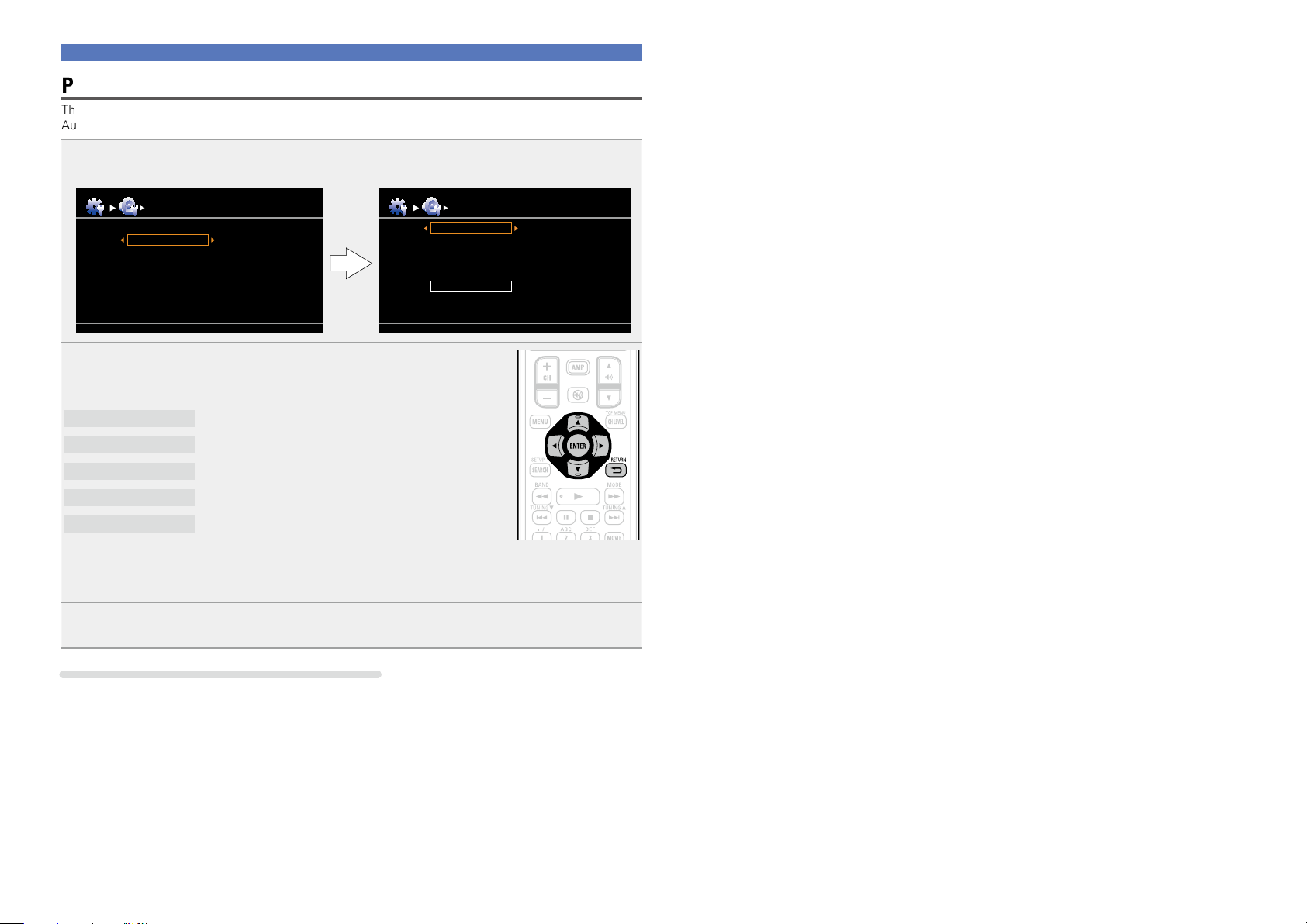
Use ui to select “Parameter Check” and then press ENTER.
1
®
Auto Setup
Auto Setup
Parameter Check
Sp. Config. Check
Distance Check
Ch. Level Check
Crossover Check
EQ Check
Parameter Check
Sp. Config. Check
Distance Check
Ch. Level Check
Crossover Check
EQ Check
Restore
Use ui to select the item you want to check, then press ENTER
2
or p.
Measurement results for each speaker are displayed.
Sp.Config. Check
Distance Check
Ch. Level Check
Crossover Check
EQ Check
•If “EQ Check” is selected, press ui to select equalizing curve (“Audyssey” or “Audyssey Flat”) to
be checked.
o p to switch the display between the different speakers.
Use
Check the speaker configuration.
Check the distance.
Check the channel level.
Check the crossover frequency.
Check the equalizer.
Press RETURN B.
3
The confirmation screen reappears. Repeat step 2.
Retrieving Audyssey® Auto Setup settings
If you set “Restore” to “Yes”, you can return to Audyssey® Auto Setup measurement result (value
calculated at the start by MultEQ® XT) even when you have changed each setting manually.
19
Page 23
Playback (Basic operation)
Basic version
Advanced version
Information
Basic version
BD
Settings (vpage13)
n Selecting the input source (vpage20)
n Adjusting the master volume (vpage21)
n Turning off the sound temporarily (vpage21)
n Playing a Blu-ray Disc player/DVD player
(vpage21)
n Playing a CD player (vpage21)
n Playing an iPod® (vpage22)
n Tuning in radio stations (vpage25)
Selecting a listening mode (Surround mode)
(vpage27)
Playback (Advanced operation) (vpage41)
Important information
Before starting playback, make the connections between the different
devices and the settings on the unit.
NOTE
Also refer to the operating instructions of the connected devices
when playing them.
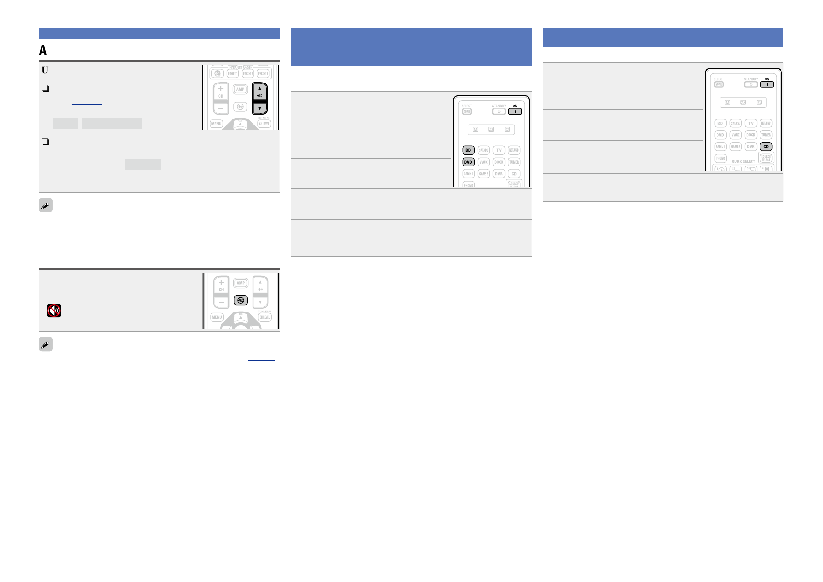
Selecting the input source
Press the input source select button
(BD, SAT/CBL, TV, DVD, V.AUX,
DOCK, TUNER, GAME1, GAME2 or
CD) to be played back.
The desired input source can be selected
directly.
•If the input source select button (TUNER, BD, SAT/CBL, TV,
GAME 1/2, DVD, DOCK, CD, V.AUX) on the main unit is pressed,
the same function as with the remote control unit can be obtained.
•When iPod 1 on the main unit is pressed, the input source of this
unit is switched to “DOCK” and the connected iPod is automatically
played (vpage24 “iPod play function”).
You can also use the following operation to select an input
source.
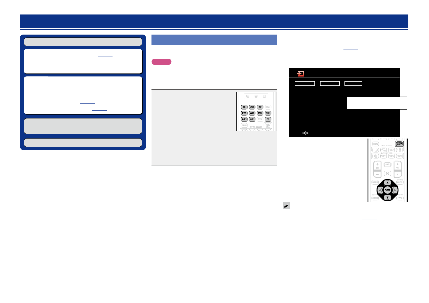
nUsing the “Source Select” menu
Switch the remote control unit to the J (MAIN ZONE) mode when
performing this operation (vpage74 “Operating AV devices”).
If the remote control unit is in K (ZONE2) mode, the “Source
Select” menu will not be displayed when SOURCE SELECT is
pressed.
Source Select
Player
BD
DVD
CD
DOCK
q Press SOURCE SELECT.
Display the “Source Select” menu.
w Use uio p to select the input source,
then press ENTER.
The input source is set and the source
selection menu is turned off.
Video
SAT/CBL
TV
GAME1
GAME2
V.AUX
Tuner
TUNER
The currently selected input
source is highlighted.
[ENTER] Enter[ ] Move
•Input sources that are not going to be used can be set ahead of time.
Make this setting at “Source Delete” (vpage65).
•To turn off the source selection menu without selecting an input
source, press SOURCE SELECT again.
•When SOURCE SELECT is pressed, the AMP-operation mode starts
automatically (vpage74).
20
Page 24
Important information
Basic version
Advanced version
Information
Basic version
BD
Adjusting the master volume
Use M df to adjust the volume.
n When the “Volume Display” setting
(vpage65) is “Relative”
GAdjustable rangeH
– – –
–80.5dB – 18.0dB
n When the “Volume Display” setting (vpage65) is
“Absolute”
GAdjustable rangeH
•The variable range differs according to the input signal and channel
level setting.
You can also operate via the main unit. In this case, perform the
following operations.
Turn MASTER VOLUME to adjust the volume.
0.0 – 99.0
Turning off the sound temporarily
Press N.
•The power indicator flashes green.
•“MUTE” indicator on the display lights.
appears on a TV screen.
•
Playing a Blu-ray Disc player/DVD player
The following describes the procedure for playing Blu-ray Disc player/
DVD player.
Prepare for playback.
q Turn on the power of the TV,
1
2
3
4
subwoofer and player.
w Change the TV input to the input of
this unit.
e Load the disc in the player.
Press ON to turn on power to the
unit.
Press BD or DVD to switch an input source for a
player used for playback.
Play the device connected to this unit.
Make the necessary settings on the player (language setting,
subtitles setting, etc.) beforehand.
Playing a CD player
The following describes the procedure for playing CD player.
Prepare for playback.
q Turn on the power of the subwoofer
1
and player.
w Load the disc in the player.
Press ON to turn on power to the
2
unit.
Press CD to switch the input
3
source to the CD player.
Play the device connected to this unit.
4
•The sound is reduced to the level set at “Mute Level” (vpage65).
•To cancel, press N again. Muting can also be canceled by adjusting
the master volume.
21
Page 25
Playing an iPod
Basic version
Advanced version
Information
Basic version
vSee overleaf
BD
If you use a separately sold DENON control dock for iPod (ASD-1R,
ASD-11R, ASD-3N, ASD-3W, ASD-51N or ASD-51W), you will be able
to play back videos, photos, music, and other content on the iPod.
The playback method differs depending on the control dock for iPod to
be used and the files to be played back (music or video).
®
nListening to music on an iPod
Prepare for playback.
q Connect the DENON control dock
1
2
3
for iPod to this unit (vpage10
“Connecting a control dock for
iPod”).
w Set the iPod in the DENON control
dock for iPod.
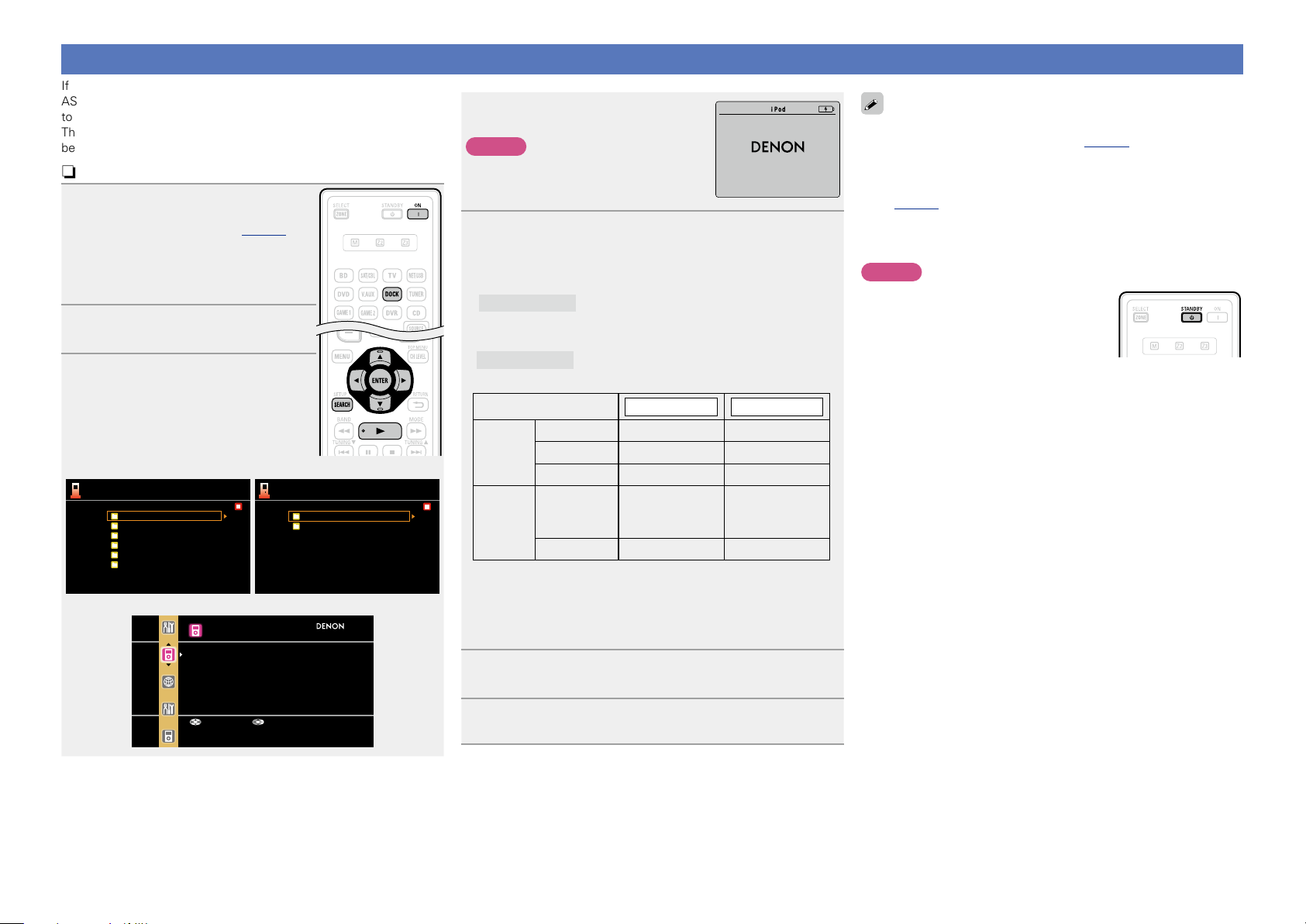
Press ON to turn on power to the
unit.
Press DOCK to switch the input
source to “DOCK”.
•If ”Browse mode” is selected in step
4, the following screen is displayed on a
TV screen, depending on the connected
control dock for iPod.
(When using an ASD-1R) (When using an ASD-11R)
Music
Playlists
Artists
Albums
Songs
Genres
Composers
GWhen using an ASD-3N, ASD-3W, ASD-51N and ASD-51WH
iPod
Music
Video
[1/6]
iPod
Music
Videos
[1/2]
•In “Browse mode”, the iPod display is as
shown at right.
NOTE
If the connections screen is not displayed,
the iPod may not be properly connected.
Reconnect it.
OK to disconnect.
Press SEARCH and hold it down for 2 seconds or
4
more to select the display mode.
•There are two modes for displaying the contents recorded on the
iPod.
Browse mode
•English letters, numbers and certain symbols are displayed.
Incompatible characters are displayed as “.” (period).
Remote mode
•“Remote iPod” is displayed on the display of this unit.
Display mode
Playable
files
Active
buttons
z1 When using an ASD-11R, ASD-3N, ASD-3W, ASD-51N or ASD-
51W DENON control dock for iPod.
z2 Video may not be output, depending on the combination of
ASD-1R, ASD-11R, ASD-3N, ASD-3W, ASD-51N or ASD-51W
DENON control dock for iPod and iPod.
Display iPod information on the TV screen.
Display iPod information on the iPod screen.
Browse mode Remote mode
Music file
Photo file
Video file
Remote
control unit
(This unit)
iPod
P P
z1
P
P P
P
P
P
z2
z2
Use ui to select the item, then press ENTER or p
5
to select the le to be played.
•You can specify the duration of the on-screen display to be displayed
(default: 30 sec) at menu “iPod” (vpage66). Press uio p to
return to the original screen.
•To play back compressed audio with extended bass or treble
reproduction, we recommend playback in RESTORER mode
(vpage57). The default setting is “Mode3”.
•In Browse mode, press STATUS on the main unit during playback
to check the title name, artist name, and album name on the display
of this unit.
NOTE
•Press STANDBY and set this unit’s power to
the standby mode before disconnecting the
iPod. You can also switch the input source
to other than “DOCK” and then disconnect
the iPod.
•Depending on the type of iPod and the software version, some
functions may not operate.
•Note that DENON will accept no responsibility whatsoever for any
problems arising with the data on an iPod when using this unit in
conjunction with the iPod.
z iPod is a trademarks of Apple Inc., registered in the U.S. and other
countries.
Up/Down Select
Press ENTER, p or 1.
6
Playback starts.
22
Page 26
nViewing videos on an iPod in the Browse mode
Basic version
Advanced version
Information
Basic version
BD
When an iPod equipped with a video function is connected to a
DENON ASD-11R, ASD-3N, ASD-3W, ASD-51N and ASD-51W
control dock for iPod, image files can be played in the Browse
mode.
Use ui to select “Videos”, then
1
press ENTER or p.
Use ui to select the search item
2
or folder, then press ENTER or
p.
Use ui to select the video le,
3
then press ENTER, p or 1.
Playback starts.
nViewing photos and videos on an iPod in the
Remote mode
This unit can play back on a TV screen photos and data stored on an
iPod equipped with a slide show or video function.
Press and hold SEARCH to set the
1
Remote mode.
“Remote iPod” is displayed on the
display of this unit.
Watching the iPod’s screen,
2
use ui to select “Photos” or
“Videos”.
•Depending on the iPod model, it may be necessary to operate the
iPod unit directly.
Press ENTER until the image you want to view is
3
displayed.
“TV Out” at the iPod’s “Slide show Settings” or “Video Settings”
must be set to “On” in order to display the iPod’s photo data or videos
on the monitor. For details, see the iPod’s operating instructions.
NOTE
Video may not be output, depending on the combination of ASD-1R,
ASD-11R, ASD-3N, ASD-3W, ASD-51N or ASD-51W and iPod.
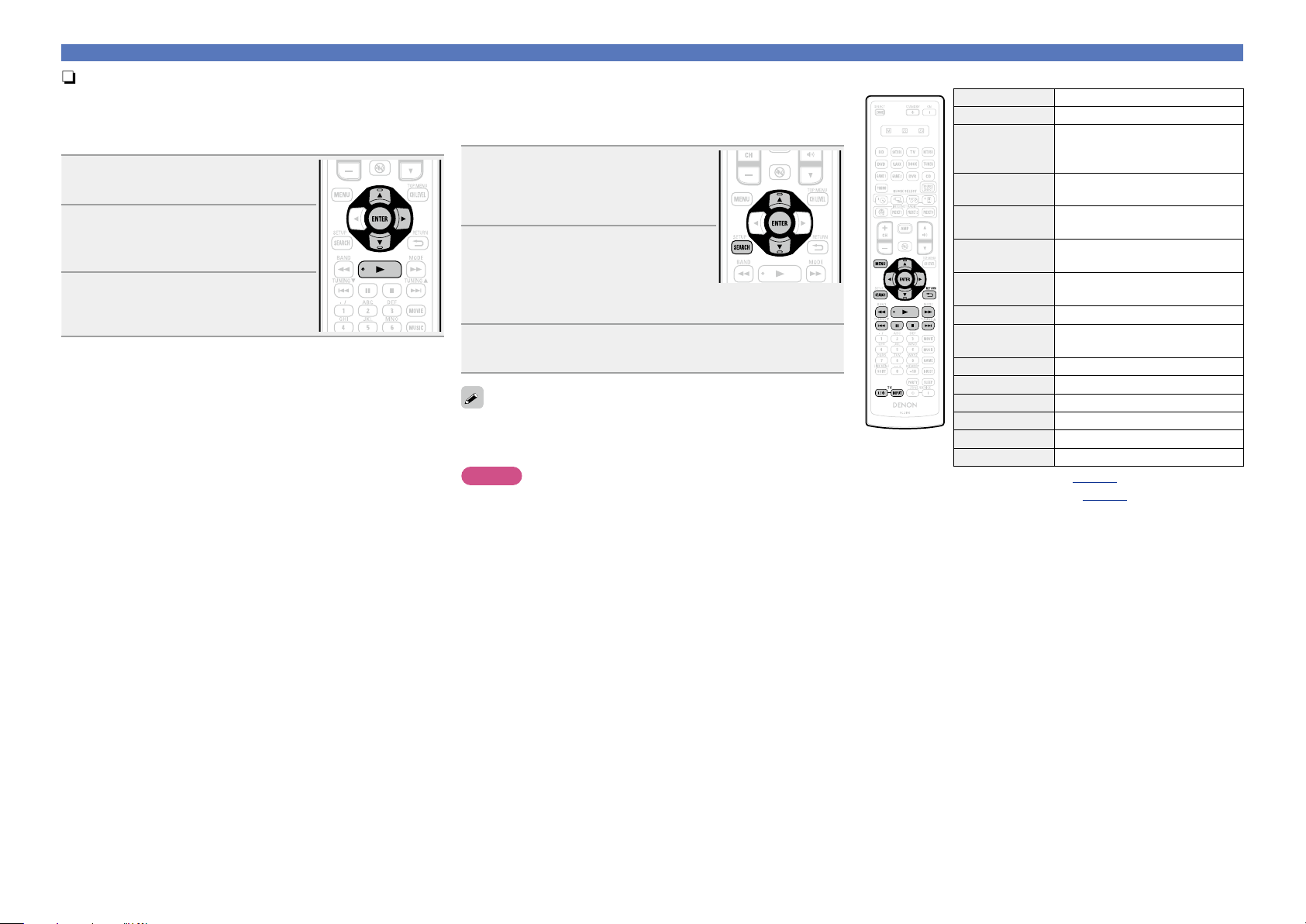
niPod operation
Operation buttons Function
MENU Amp menu
uio p
ENTER
(Press and release)
ENTER
(Press and hold)
SEARCH
(Press and release)
SEARCH
(Press and hold)
RETURN B
6 7
(Press and hold)
1
8 9
3
2
TV Z / X
TV INPUT Switch TV input (Default : SONY)
•Repeat playback (vpage73 “Repeat”)
•Shuffling playback (vpage73 “Shuffle”)
z When the menu screen is displayed, press
(previous page) or p (next page).
To cancel, press ui or SEARCH.
Auto search (cue, ui) /
Manual search (Press and hold, ui)
Page search mode
(for ASD-1R, ASD-11R)
Browse / Remote mode switching
(fast-reverse/fast-forward)
TV power on/standby (Default : SONY)
Playing an iPod
Cursor operation /
Enter / Pause
Stop
z
Return
Manual search
Playback / Pause
Auto search (cue)
Pause
Stop
SEARCH, then press o
23
Page 27
Playing an iPod
Basic version
Advanced version
Information
Basic version
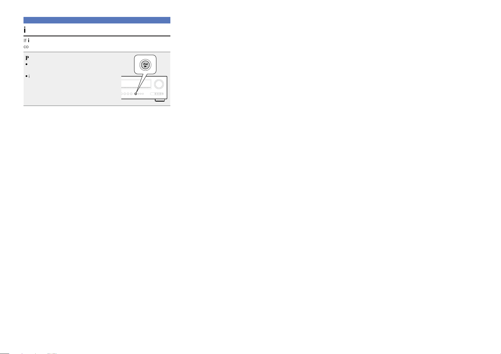
BD
iPod play function
If iPod 1 on the main unit is pressed when a control dock for iPod is
connected, the iPod starts playback.
Press iPod 1.
•This unit’s input source switches to
“DOCK”.
•iPod playback starts.
24
Page 28
Tuning in radio stations
Basic version
Advanced version
Information
Basic version
vSee overleaf
BD
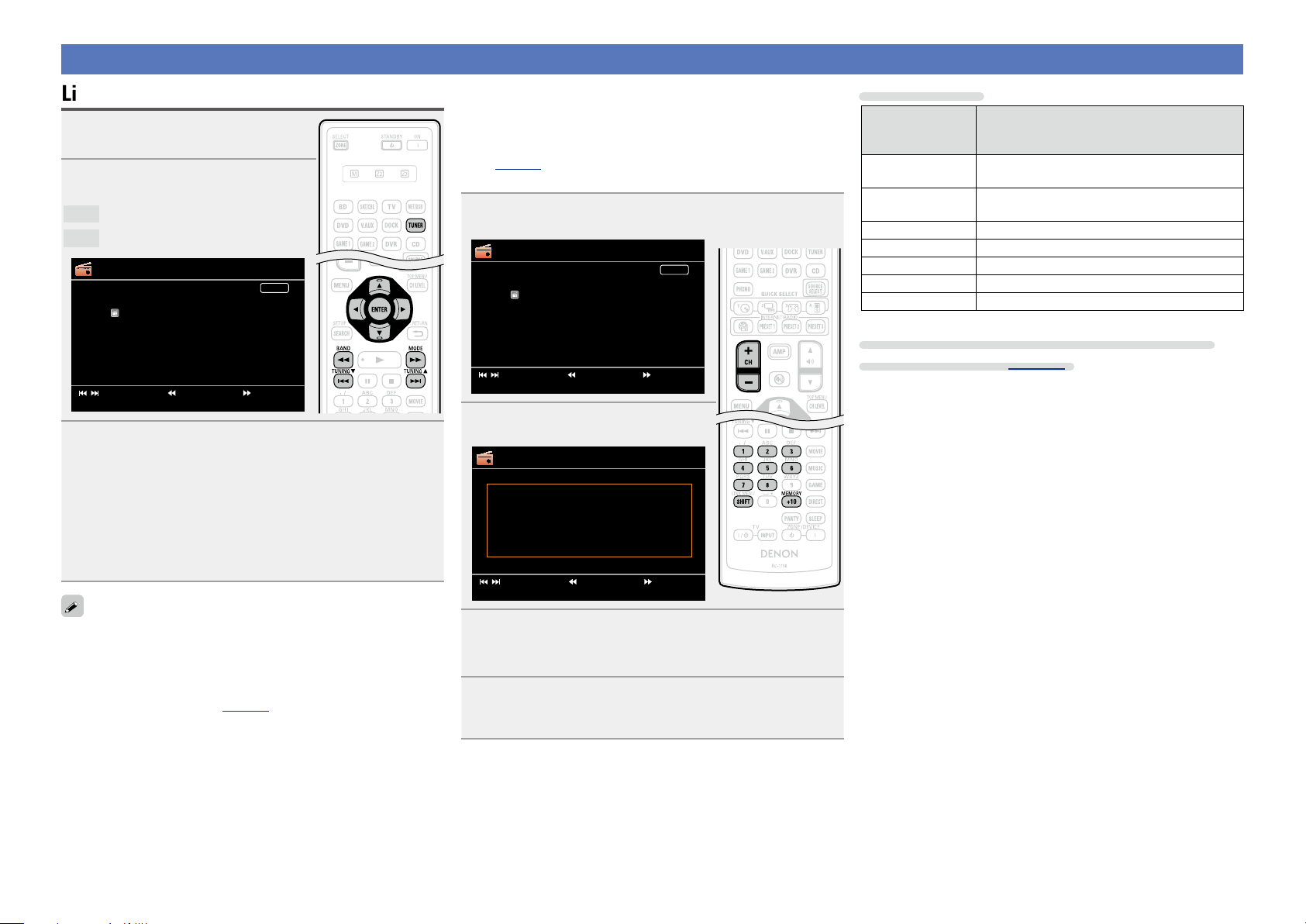
Listening to FM/AM broadcasts
Press TUNER to switch the input
1
source to “TUNER”.
Press BAND to select “FM” or
2
“AM”.
FM
When listening to an FM broadcast.
AM
When listening to an AM broadcast.
TUNER
AUTO
[
CH+/-
FM 87.50MHz
Tuning[ / ]
] Preset
[
MEMORY
[
]
]
Band
Memory
Now Playing
A1
[
[
SEARCH
] Mode
] Search
Tune in the desired broadcast station.
3
q To tune in automatically (Auto tuning)
Press MODE to light the “AUTO” indicator on the display, then
use TUNING d or TUNING f to select the station you want to
hear.
w To tune in manually (Manual tuning)
Press MODE to turn off the display’s “AUTO” indicator, then use
TUNING d or TUNING f to select the station you want to hear.
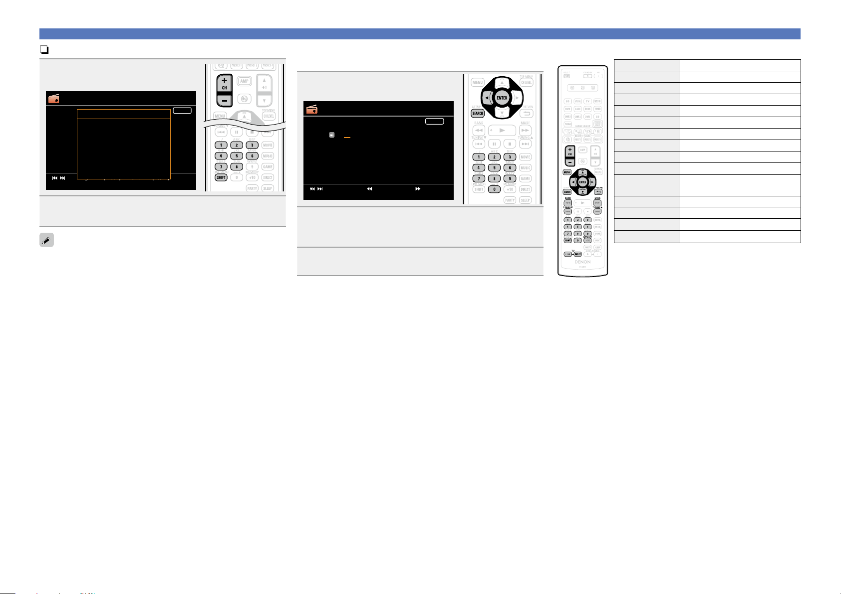
nPresetting radio stations (Manual preset)
Your favorite broadcast stations can be preset so that you can tune
them in easily. Up to 56 stations can be preset.
•Stations can be preset automatically at “Auto Preset”
(vpage69). If “Auto Preset” is performed after performing
“Manual preset”, the “Manual preset” settings will be overwritten.
Tune in the broadcast station you want to preset.
1
TUNER
AUTO
[
CH+/-
FM 87.50MHz
Tuning[ / ]
] Preset
[
MEMORY
[
]
]
Band
Memory
Now Playing
A1
[
[
SEARCH
] Mode
] Search
Press MEMORY.
2
TUNER
To store preset:
A1-G8
Select
[
MEMORY
[
CH+/-
SHIFT
Tuning[ / ]
] Preset
]
1-8
][
[
MEMORY
]
Band
]
Memory
][
[
[
SEARCH
A1
] Mode[
] Search
Default settings
Block (A – G)
and
Default Settings
Channel (1 – 8)
A1 – A8
B1 – B8
87.50 / 89.10 / 98.10 / 107.90 / 90.10 / 90.10 /
90.10 / 90.10 MHz
520 / 600 / 1000 / 1400 / 1500 / 1710 kHz,
90.10 / 90.10 MHz
C1 – C8 90.10 MHz
D1 – D8 90.10 MHz
E1 – E8 90.10 MHz
F1 – F8 90.10 MHz
G1 – G8 90.10 MHz
Specify a name for the preset broadcast station
(Preset Name) (vpage69)
•If the desired station cannot be tuned in with auto tuning, tune it in
manually.
•When tuning in stations manually, press and hold TUNING d or
TUNING f to change frequencies continuously.
•The time (default : 30 sec) for which the menu are displayed can be
set at menu “Tuner” (vpage 66). Press uio p to return to
the original screen.
Press SHIFT to select the block (A to G) in which the
3
channel (1 to 8 per a block) is to be preset, then press
CH +, CH – or 1 – 8 to select the preset number.
Press MEMORY again to complete the setting.
4
•To preset other stations, repeat steps 1 to 4.
25
Page 29
nListening to preset stations
Basic version
Advanced version
Information
Basic version
BD
Press SHIFT to select the memory
1
block (A to G).
TUNER
Preset Channel
A8 FM 90.10MHz
A7 FM 90.10MHz
A6 FM 90.10MHz
A5 FM 90.10MHz
A4 FM 107.90MHz
A3 FM 98.10MHz
A2 FM 89.10MHz
A1 FM 87.50MHz
[
CH+/-
Tuning[ / ]
] Preset
[
MEMORY
]
Band
]
Memory
Press CH +, CH – or 1 – 8 to select the desired preset
2
channel.
You can also operate via the main unit. In this case, perform the
following operations.
Press TUNER PRESET CH + or TUNER PRESET CH – to select a preset
radio station.
AUTO
] Mode[
[
nDirect frequency tuning
You can enter the receiving frequency directly to tune in.
Press SEARCH.
1
TUNER
AUTO
[
CH+/-
FM ---.- MHz
DIRECT TUNE
Tuning[ / ]
] Preset
[
MEMORY
]
]
Band
Memory
Now Playing
B6
[
[
SEARCH
] Mode[
] Search
Input frequencies using the 0 – 9.
2
•If o is pressed, the immediately preceding input is cancelled.
When setting is completed, press ENTER.
3
The preset frequency is tuned in.
nTuner (FM/AM) operation
Operation buttons Function
CH +, – Preset channel selection
MENU Amp menu
uio p
ENTER Enter
SEARCH Direct frequency tuning
RETURN B
BAND FM/AM switching
MODE Switch search modes
TUNING df
0 – 9
SHIFT Preset channel block selection
MEMORY Preset memory registration
TV Z / X
TV INPUT Switch TV input (Default : SONY)
Tuning in radio stations
Cursor operation
Return
Tuning (up/down)
Preset channel selection (1 – 8) /
Direct frequency tuning (0 – 9)
TV power on/standby (Default : SONY)
26
Page 30
Selecting a listening mode (Surround mode)
Basic version
Advanced version
Information
Basic version
vSee overleaf
This unit can play input audio signals in multi-channel surround mode
or in stereo mode.
Select a listening mode suitable for the playback contents (cinema,
music, etc.) or according to your liking.
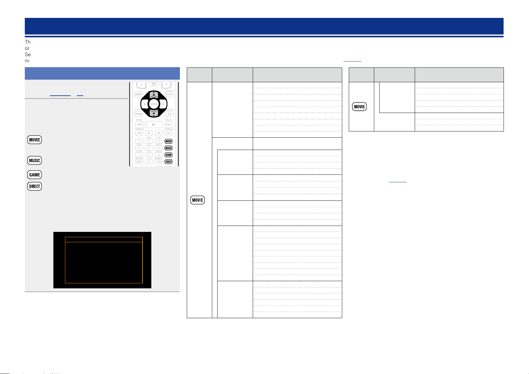
Selecting a listening mode
Play the selected device
1
(vpage 21 – 25).
Press MOVIE, MUSIC, GAME or
2
DIRECT to select a listening mode.
•Each time MOVIE, MUSIC or GAME is
pressed, the listening mode is switched.
Switches to the listening mode
suitable for enjoying movies and TV
programs.
Switches to the listening mode
suitable for enjoying music.
Switches to the listening mode suitable for enjoying games.
Switches the listening mode to Direct or Pure Direct mode.
In Direct mode, the audio is played back exactly how it was
recorded.
•Pressing
modes that can be selected on the TV screen. While the list is
displayed, you can also use ui to select a surround mode.
MOVIE, MUSIC or GAME displays a list of the surround
GExampleH When MOVIE is pressed
MOVIE SURROUND
STEREO
DOLBY PLII Cinema
DOLBY Pro Logic
DTS NEO:6 cinema
MULTI CH STEREO
MONO MOVIE
nListening mode
•The following listening modes can be selected using the MOVIE, MUSIC, GAME, and DIRECT buttons.
•Adjust the sound field effect with the menu “Surr.Parameter” (vpage53) to enjoy your favorite sound mode.
Operation
button
Input signal Listening mode
STEREO
DOLBY PLgx Cinema
DOLBY PLg Cinema
DOLBY Pro Logic
2-channel
Multi-channel
z3
z1
Dolby Digital
Dolby TrueHD
Dolby Digital
Plus
DTS
DTS-HD /
DTS Express
DTS NEO:6 Cinema
DOLBY PLgz Height
MULTI CH STEREO
MONO MOVIE
VIRTUAL
STEREO
DOLBY DIGITAL
DOLBY DIGITAL EX
DOLBY DIGITAL + PLgx Cinema
DOLBY DIGITAL + PLgz
DOLBY TrueHD
DOLBY TrueHD + EX
DOLBY TrueHD + PLgx Cinema
DOLBY TrueHD + PLgz
DOLBY DIGITAL Plus
DOLBY DIGITAL Plus + EX
DOLBY DIGITAL Plus + PLgx Cinema
DOLBY DIGITAL Plus
DTS SURROUND
DTS ES DSCRT 6.1
DTS ES MTRX 6.1
DTS 96/24
DTS 96 ES MTRX
DTS ES DSCRT
DTS + NEO:6
DTS + PLgx Cinema
DTS + PLgz
DTS-HD HI RES
DTS-HD MSTR
DTS Express
DTS-HD + NEO:6
DTS-HD + PLgx Cinema
DTS-HD + PLgz
z2
z2
z2
z2
z2
+ PLgz
Operation
button
z1 2-channel also includes analog input.
z2 This mode plays back 2-channel source in 5.1 or 7.1-channel
playback. It cannot be selected when headphones are used, or
when only front speakers are used.
z3 Some listening modes cannot be selected, depending on the
audio format or number of channels of the input signal. For
details, see “Types of input signals, and corresponding surround
modes” (vpage89).
Input signal Listening mode
MULTI CH IN
PCM multichannel
Multi-channel
z3
MULTI CH IN 7.1
MULTI IN + Dolby EX
MULTI IN + PLgx Cinema
MULTI IN + PLgz
MULTI CH STEREO
MONO MOVIE
VIRTUAL
27
Page 31

Basic version
Advanced version
Information
Basic version
vSee overleaf
Operation
button
Input signal Listening mode
STEREO
DOLBY PLgx Music
DOLBY PLg Music
DTS NEO:6 Music
2-channel
Multi-channel
Multi-channel
z1
Dolby Digital
Dolby TrueHD
Dolby Digital
Plus
DTS
DTS-HD /
DTS Express
PCM multichannel
DOLBY PLgz Height
MULTI CH STEREO
ROCK ARENA
JAZZ CLUB
MATRIX
VIRTUAL
z3
STEREO
DOLBY DIGITAL
DOLBY DIGITAL EX
DOLBY DIGITAL + PLgx Music
DOLBY DIGITAL + PLgz
DOLBY TrueHD
DOLBY TrueHD + EX
DOLBY TrueHD + PLgx Music
DOLBY TrueHD + PLgz
DOLBY DIGITAL Plus
DOLBY DIGITAL Plus + EX
DOLBY DIGITAL Plus + PLgx Music
DOLBY DIGITAL Plus
DTS SURROUND
DTS ES DSCRT 6.1
DTS ES MTRX 6.1
DTS 96/24
DTS 96 ES MTRX
DTS ES DSCRT
DTS + NEO:6
DTS + PLgx Music
DTS + PLgz
DTS-HD HI RES
DTS-HD MSTR
DTS Express
DTS-HD + NEO:6
DTS-HD + PLgx Music
DTS-HD + PLgz
MULTI CH IN
MULTI CH IN 7.1
MULTI IN + Dolby EX
MULTI IN + PLgx Music
MULTI IN + PLgz
MULTI CH STEREO
ROCK ARENA
z3
JAZZ CLUB
MATRIX
VIRTUAL
z2
z2
z2
z2
+ PLgz
Operation
button
Input signal Listening mode
STEREO
DOLBY PLgx Game
2-channel
Multi-channel
Multi-channel
All
z1
Dolby Digital
Dolby TrueHD
Dolby Digital
Plus
DTS
DTS-HD /
DTS Express
PCM multichannel
DOLBY PLg Game
DOLBY PLgz Height
MULTI CH STEREO
VIDEO GAME
VIRTUAL
z3
STEREO
DOLBY DIGITAL
DOLBY DIGITAL EX
DOLBY DIGITAL + PLgz
DOLBY TrueHD
DOLBY TrueHD + EX
DOLBY TrueHD + PLgz
DOLBY DIGITAL Plus
DOLBY DIGITAL Plus + EX
DOLBY DIGITAL Plus
DTS SURROUND
DTS ES DSCRT 6.1
DTS ES MTRX 6.1
DTS 96/24
DTS 96 ES MTRX
DTS ES DSCRT
DTS + NEO:6
DTS + PLgz
DTS-HD HI RES
DTS-HD MSTR
DTS Express
DTS-HD + NEO:6
DTS-HD + PLgz
MULTI CH IN
MULTI CH IN 7.1
MULTI IN + Dolby EX
MULTI IN + PLgz
MULTI CH STEREO
z3
VIDEO GAME
VIRTUAL
DIRECT
PURE DIRECT
z2
z2
z2
+ PLgz
Selecting a listening mode
z1 2-channel also includes analog input.
z2 This mode plays back 2-channel source in 5.1 or 7.1-channel
playback. It cannot be selected when headphones are used, or
when only front speakers are used.
z3 Some listening modes cannot be selected, depending on the
audio format or number of channels of the input signal. For
details, see “Types of input signals, and corresponding surround
modes” (vpage89).
Views on the TV screen or display
q w
q Shows a decoder to be used.
•A DOLBY DIGITAL Plus decoder is displayed as “DOLBY D +”.
w Shows a decoder that creates sound output from the surround
back speakers.
•“+ PLgz” indicates the front height sound from front height
speakers.
28
Page 32

nDescription of listening mode types
Basic version
Advanced version
Information
Basic version
vSee overleaf
Selecting a listening mode
Dolby listening mode
Listening mode type Description
DOLBY PLgx
DOLBY PLg This mode can be selected when a Dolby Pro Logic g decoder is used to play
DOLBY Pro Logic This mode can be selected when a DOLBY Pro Logic decoder is used to play
DOLBY PLgz
DOLBY DIGITAL This mode can be selected when playing sources recorded with Dolby Digital.
DOLBY DIGITAL EX
DOLBY TrueHD This mode can be selected when playing sources recorded in Dolby TrueHD.
DOLBY DIGITAL Plus This mode can be selected when playing sources recorded with Dolby Digital
z1 This can be selected when “Speaker Config.” – “S.Back” is not set to “None”.
z2 This can be selected when “Speaker Config.” – “F.Height” is not set to “None”.
z1
z2
This mode can be selected when a Dolby Pro Logic gx decoder is used to
play back 2-channel source in 6.1/7.1-channel surround sound including the
surround back channel.
By adding the surround back channel, a stronger surround feeling is obtained
compared to Dolby Pro Logic g.
There are three playback modes: “Cinema” mode that is optimized for movie
playback, “Music” mode that is optimized for music playback, and “Game”
mode that is optimized for game play.
back 2-channel source in 5.1-channel surround sound with a natural, realistic
feel.
2-channel source in 4.1-channel surround sound (Left/Center/Right/Surround
Mono).
This mode can be selected when a Dolby Pro Logic gz decoder is used to play
back 2-channel source in 7.1-channel surround sound with added front height
channel.
By adding a front height channel, the vertical expression is emphasized,
improving the three-dimensionality of the sound.
z1
This mode improves the depth, dimension, and expressiveness of the sound
stage by sound field playback including surround back channels.
Plus.
DTS listening mode
Listening mode type Description
DTS NEO:6 This mode can be selected when a DTS NEO:6 decoder is used to play back
2-channel source in 6.1/7.1-channel surround sound including the surround
back channel.
There is a “Cinema” mode optimized for movie playback, and a “Music” mode
optimized for music playback.
DTS SURROUND This mode can be selected when playing sources recorded in DTS.
DTS ES DSCRT6.1
DTS ES MTRX6.1
DTS 96/24 This mode can be selected when playing sources recorded in DTS 96/24.
DTS-HD This mode can be selected when playing sources recorded in DTS-HD.
DTS Express This mode can be selected when playing sources recorded in DTS Express.
z This can be selected when “Speaker Config.” – “S.Back” is not set to “None”.
z
This mode can be selected when playing sources recorded in DTS-ES.
Provides optimum playback of DTS-ES Discrete signals using surround back.
z
This mode can be selected when playing sources recorded in DTS-ES.
Surround back channel data encoded in DTS-ES Matrix recording software is
played from the surround back channel.
PCM multi-channel listening mode
Listening mode type Description
MULTI CH IN This mode can be selected when playing multi-channel PCM sources .
29
Page 33

Selecting a listening mode
Basic version
Advanced version
Information
Basic version
DENON original listening mode
Listening mode type Description
MULTI CH STEREO This mode is for enjoying stereo sound from all speakers.
The same sound as that from the front speakers (L/R) is played back at the
same level from the surround speakers (L/R) and surround back speakers (L/R).
ROCK ARENA This mode is for enjoying the atmosphere of a live concert in an arena.
JAZZ CLUB This mode is for enjoying the atmosphere of a live concert in a jazz club.
MONO MOVIE This mode is for playing monaural movie sources with surround sound.
When playing sources recorded in monaural in the “MONO MOVIE” mode,
the sound will be off balance with a single channel (left or right), so input to
both channels.
VIDEO GAME This mode is suited for achieving surround sound with video games.
MATRIX This mode lets you add a spacious feel to stereo music sources.
VIRTUAL This mode is for enjoying surround effects using only the front speakers or
headphones.
STEREO listening mode
Listening mode type Description
STEREO This is the mode for playing in stereo. The tone can be adjusted.
•Sound is output from the front left and right speakers and subwoofer.
•If multichannel signals are input, they are mixed down to 2-channel audio and
are played.
Direct listening mode
Listening mode type Description
DIRECT Sound recorded in source is played as is.
•Surround back signals or front height signals are not created.
PURE DIRECT This mode is for playback in higher sound quality than in “Direct playback”
mode.
Turn the display of the amplifier off to stop the analogue video circuit. This
suppresses the source of noise that affects sound quality.
•Surround back signals or front height signals are not created.
In Direct listening mode, the following items cannot be adjusted.
•Tone (vpage55) •MultEQ® XT (vpage55) •Dynamic EQ® (vpage56)
•Dynamic Volume® (
NOTE
•Video signals are only output when HDMI signals are played in the PURE DIRECT mode.
•When in the PURE DIRECT mode, the menu screen is not displayed.
vpage56)•RESTORER (vpage57)
30
Page 34

Advanced
Basic version
Advanced version
Information
Advanced version
version
Advanced version
Here, we explain functions and operations that let you make better use of this unit.
F Speaker installation/connection (Advanced connection) vpage32
F Playback (Advanced operation) vpage41
F Playback in ZONE2 (Separate room) vpage45
F How to make detailed settings vpage47
F Operating the connected devices by remote control unit vpage74
31
Page 35

Speaker installation/connection (Advanced connection)
Basic version
Advanced version
Information
Advanced version
vSee overleaf
Here we describe the installation, connection and
setup methods for speakers other than 5.1-channel
speakers. For the installation, connection and setup
methods for 5.1-channel speakers, see C page 4
“Setup Wizard”.
Use Audyssey® Auto Setup function of this unit
to automatically detect the number of connected
speakers and perform optimal settings for the
speakers to be used.
Procedure for speaker settings
Install
Connect (vpage34)
Set up speakers (vpage39)
Install
This unit is compatible with Dolby Pro Logic gz (vpage 92),
which offers an even wider and deeper surround sensation.
When using Dolby Pro Logic gz, install front height speakers.
Install the surround back speakers in a position 2 to 3 ft (60 to 90 cm)
higher than ear level.
Front height
speaker
•Point slightly
downwards
At least
3.3 ft / 1 m
z Recommended for Dolby Pro Logic gz
z
Front
speaker
GViewed from the sideH
NOTE
It is not possible to use the surround back speakers and front height
speakers simultaneously.
Surround
speaker
2 – 3 ft /
60 – 90 cm
Surround back
speaker
•Point slightly
downwards
When 7.1ch (Surround back speaker) installed
FL FR
SW
C
z1
z2
z3
SL
Listening
position
SBL SBR
z1 22˚ – 30˚ z2 90˚ – 110˚ z3 135˚ – 150˚
GSpeaker abbreviationsH
FL Front speaker (L) SL Surround speaker (L)
FR Front speaker (R) SR Surround speaker (R)
C Center speaker SBL Surround back speaker (L)
SW Subwoofer SBR Surround back speaker (R)
SR
32
Page 36

When 7.1ch (Front height speaker) installed
Basic version
Advanced version
Information
Advanced version
FHRFHL
When 6.1ch (Surround back speaker) installed
Install
When Front A/B speakers installed
FR
C
z3
SR
SL
FL
SW
z2
z1
Listening position
z1 22˚ – 30˚ z2 22˚ – 45˚ z3 90˚ – 110˚
GSpeaker abbreviationsH
FL Front speaker (L) SB Surround back speaker
FR Front speaker (R) FHL Front height speaker (L)
C Center speaker FHR Front height speaker (R)
SW Subwoofer
SL Surround speaker (L)
SR Surround speaker (R)
FL FR
SW
C
z1
z2
SL
Listening position
SB
z1 22˚ – 30˚ z2 90˚ – 110˚
SR
FL(B) FL(A)
SW
FR(A) FR(B)
Listening position
33
Page 37

Connect
Basic version
Advanced version
Information
Advanced version
•For the method of connecting 5.1-channel speakers, see C page 6 “Connecting the speakers”.
•For the method of connecting the TV, see C page 3 “Connect this unit to the television using an HDMI
cable (sold separately)”.
7.1-channel (Surround back speaker) connection
The illustration on the right shows a connection example for performing 7.1-channel playback using the
surround back speakers.
If you connect the surround back and front height speakers before you start playback, the audio is played
back by automatically switching the speakers in accordance with the surround mode or input signals.
To perform 7.1-channel playback using the surround back speakers, set “Amp Assign” to “NORMAL” in
steps 3 and 4 for “Set up “Amp Assign”” (vpage39).
NOTE
•For speaker cable connections, see C page 6 “Connecting the speakers”.
•Connect so that the speaker cable core wires do not protrude from the speaker terminal. The
protection circuit may be activated if the core wires touch the rear panel or if the + and – sides
touch each other (vpage93 “Protection Circuit”).
•Never touch the speaker terminals while the power supply is connected. Doing so could result
in electric shock. (When the Setup wizard is running, follow the instructions in the Setup wizard
screen for making connections.)
•Use speakers with the speaker impedances shown below.
Speaker terminals Speaker impedance
FRONT
CENTER
SURROUND
SURR. BACK / AMP ASSIGN
6 – 16 Ω
FL FR
SW
34
SL
C
SR
SBL SBR
Page 38

7.1-channel (Front height speaker) connection
Basic version
Advanced version
Information
Advanced version
The illustration on the right shows a connection example for performing 7.1-channel playback using the
front height speakers.
If you connect the surround back and front height speakers before you start playback, the audio is played
back by automatically switching the speakers in accordance with the surround mode or input signals.
To perform 7.1-channel playback using the front height speaker, set “Amp Assign” to “F.HEIGHT” in steps
3 and 4 for “Set up “Amp Assign”” (vpage39).
NOTE
•For speaker cable connections, see C page 6 “Connecting the speakers”.
•For speaker impedance, see page34.
Connect
35
SL
FL FR
SW
C
FHRFHL
SR
Page 39

6.1-channel (Surround back speaker) connection
Basic version
Advanced version
Information
Advanced version
If using only one surround back speaker (with a 6.1-channel connection), connect to the “L” side of the
SURR. BACK/AMP ASSIGN terminal.
For speaker settings in this case, see “When 6.1ch (Surround back speaker) installed” (vpage33).
To perform 6.1-channel playback using the surround back speaker, set “Amp Assign” to “NORMAL” in
steps 3 and 4 for “Set up “Amp Assign”” (vpage39).
Also use the “Speaker Config.” setting (vpage60) to set “S.Back” to “1spkr”.
NOTE
•For speaker cable connections, see C page 6 “Connecting the speakers”.
•For speaker impedance, see page34.
FL FR
SW
Connect
36
SL
C
SR
SB
Page 40

Front A/B connection
Basic version
Advanced version
Information
Advanced version
You can connect a second set of speakers to this unit and use them for playback.
In this case, set “Amp Assign” to “Front B” in steps 3 and 4 for “Set up “Amp Assign”” (vpage39).
SW
FL(A)FL(B) FR(B)FR(A)
2.1-channel connection
FL FR
SW
Connect
NOTE
•For speaker cable connections, see C page 6 “Connecting the speakers”.
•For speaker impedance, see page34.
For surround playback of a multichannel source, if you connect the center speaker, surround speakers and
subwoofers, 5.1-channel playback is available.
Front speakers can be used separately, depending on the speaker’s specifications or playback source such
as front speakers (A) for multichannel playback and front speakers (B) for 2-channel playback (vpage62
“Front Sp Setup”).
NOTE
•For speaker cable connections, see C page 6 “Connecting the speakers”.
•For speaker impedance, see page34.
37
Page 41

Bi-Amp connection
Basic version
Advanced version
Information
Advanced version
You can use the front speakers via the bi-amp connection.
A bi-amp connection is to connect separate amplifiers to the tweeter terminals and woofer terminals of
speakers compatible with the bi-amp function. This prevents the back electromotive force (returned force
without output) of the woofer sent to the tweeter, which affects the sound quality of the tweeter, and you
can enjoy playback with higher-quality sound.
In this case, set “Amp Assign” to “Bi-AMP” in steps 3 and 4 for “Set up “Amp Assign”” (vpage39).
For surround playback of a multichannel source, if you connect the center speaker, surround speakers and
subwoofers, 5.1-channel playback is available.
NOTE
•For speaker cable connections, see C page 6 “Connecting the speakers”.
•For speaker impedance, see page34.
•Use speakers compatible with bi-amp connections.
•When making bi-amp connections, be sure to remove the short-circuiting plate or wire between the
speaker’s woofer and tweeter terminals.
wq wq
FL FR
SW
Connect
(R) (L)
38
Page 42

Set up speakers
Basic version
Advanced version
Information
Advanced version
vSee overleaf
Here we describe how to set up speakers other than 5.1-channel speakers.
For the method of setting up 5.1-channel speakers, see C page 4 “Setup wizard”.
First install and connect the speakers to this unit.
Before Auto Setup measurement, the settings shown below can be made.
•Changing the amplifier assignment (Amp Assign)
The signal output from the SURR.BACK/AMP ASSIGN speaker terminal of this unit can be switched to match your speaker environment (vpage39 “Set up “Amp Assign””).
•Setting the channels to be used (Channel Select)
If channels that are not to be used are set in advance, measurement for the set channels is skipped, and measuring time can be reduced. You can also change the number of surround back speakers (vpage40
“Set up “Channel Select””).
around items indicate the settings.
1
Set up the
remote control unit
n Set up the zone mode
Press ZONE SELECT to switch the zone mode to
J (MAIN ZONE).
The J indicator lights.
Press ZONE SELECT
n Set up the operation mode
Press AMP to set the remote control unit to AMPoperation mode.
Press AMP
Connect the setup microphone.
2
When the setup microphone is
connected, the following screen is
displayed.
Audyssey Auto Setup
Preparation
Connect the speakers and place then according
to the recommendations in the manual.
Next
Select “Next”, and then press
3
ENTER.
MultEQ XT
[RETURN][ENTER] Enter Cancel
4
Set up “Amp Assign”
Use ui to select “Amp Assign”, and then press
ENTER.
Audyssey Auto Setup
Preparation
Set the following items
if necessary.
Amp Assign
Channel Select
Auto Setup Start
Amp Assign
Amp Assign ZONE2
MultEQ XT
[RETURN][ENTER] Enter Cancel
MultEQ XT
ZONE2
[RETURN] Return
39
Page 43

Set up speakers
Basic version
Advanced version
Information
Advanced version
Use o p to select the
5
conguration of the connected
speakers.
NORMAL
ZONE2
Bi-AMP
Front B
F.HEIGHT
Select the “NORMAL” setting to perform
7.1-channel playback using the surround back
speakers.
Select the “ZONE2” setting to assign the unit’s
built-in power amplifier for ZONE2 and output the
audio in stereo.
Select the “Bi-AMP” setting to connect the front
speakers via the bi-amp connection.
Select the “Front B” setting to use the second set
of front speakers for playback.
Select the “F.HEIGHT” setting to use the front
height speaker for playback.
Press RETURN B to exit the “Amp Assign” setting.
6
7
Set up “Channel Select”
Use ui to select “Channel Select”, and then press
ENTER.
Audyssey Auto Setup
Preparation
Set the following items
if necessary.
Amp Assign
Channel Select
Auto Setup Start
Channel Select
Subwoofer Measure
Use ui to select a channel.
MultEQ XT
[RETURN][ENTER] Enter Cancel
[RETURN] Return
8
Press o p to select a front speaker.
9
A
Select this to use front speaker A.
B
Select this to use front speaker B.
A+B
Select this to use front speakers A and B simultaneously.
Use o p to set whether or not a subwoofer channel
10
is measured.
Measure Set for measuring a subwoofer.
Skip
Set for no measuring of a subwoofer.
Use o p to set whether or not a surround back
11
channel is measured.
Measure
Measure
12
NOTE
After performing Audyssey® Auto Setup, do not change the speaker
connections or subwoofer volume. In event of a change, perform
Audyssey® Auto Setup again.
Set for measuring two surround back speakers.
(2 sp)
Set for measuring a surround back speaker.
(1 sp)
Set for no measuring of a surround back speaker.
Skip
Press RETURN B.
Proceed to page15
STEP1 Preparation
step 6.
Front
Subwoofer
Surround
Back
Select for setting the front speakers to be used. In this
case, go to step 9.
•“Front” can be set when “Amp Assign” is set to
“Front B”.
Select for no subwoofer to be used. In this case, go
to step 10.
Select the number of surround back speakers to be
used. In this case, go to step 11.
•“Surround Back” can be set when “Amp Assign” is
set to “NORMAL”.
40
Page 44

Playback (Advanced operation)
Basic version
Advanced version
Information
Advanced version
vSee overleaf
BD
Settings (vpage13)
Playback (Basic operation) (vpage20)
Selecting a listening mode (Surround mode)
(vpage27)
n HDMI control function (vpage41)
n Sleep timer function (vpage42)
n Adjusting the volume of the speakers
(vpage43)
n Quick select function (vpage44)
n Various memory functions (vpage44)
Convenient functions
HDMI control function
If you connect the unit and an HDMI control function compatible TV or
player with an HDMI cable and then enable the HDMI control function
setting on each device, the devices will be able to control each other.
nOperations possible by HDMI control
•This unit power off can be linked to the TV power off step.
•You can switch audio output devices with a TV operation.
When you set “Output audio from amp” in the TV audio output
setup operation, you can switch the amp power on.
•You can adjust this unit volume in the TV volume adjustment
operation.
•You can switch this unit input sources through linkage to TV
input switching.
•When playing the player, this unit input source switches to the
source for that player.
•If you switch the input source of the unit to “TV”, you can
play TV audio with this unit (vpage6 “About ARC (Audio
Return Channel) function”).
•When “HDMI Control” (vpage 63) in the menu is set to
“ON”, signals input to the HDMI input connector are output to
the television or other device connected to the HDMI output
connector, even if the power of this unit is in standby (passthrough function).
•To play the audio of a TV that does not support the ARC function
with the unit, connect the TV with an optical digital connection.
•To use the pass-through function, connect an HDMI connection
device that is compatible with HDMI control.
nSetting procedure
Set the HDMI output connector corresponding with
1
the HDMI control function.
Set “HDMI Control” (vpage63) to “ON“.
Turn the power on for all the devices connected by
2
HDMI cable.
Set the HDMI control function for all devices
3
connected by HDMI cable.
•Please consult the operating instructions for the connected devices
to check the settings.
•Carry out steps 2 and 3 should any of the devices be unplugged.
Switch the television input to the HDMI input
4
connected to this unit.
Switch this unit input to the HDMI input source and
5
check if the picture from the player is ok.
When you turn the TV’s power to standby, check
6
that the power of this unit also goes to standby.
If the HDMI control function does not operate properly, check the
following points.
•Is the TV or player compatible with the HDMI control function?
•Is “HDMI Control” (vpage63) set to “ON”?
•Is “P.Off Control” (vpage63) set to “All” or “Video”?
•Are the HDMI control function settings of all devices correct?
41
Page 45

Convenient functions
OFF 10 min 20 30 40 50
Basic version
Advanced version
Information
Advanced version
BD
NOTE
•When “HDMI Control” is set to “ON”, it consumes more
standby power.
•The HDMI control function controls operations of a TV that is
compatible with the HDMI control function. Make sure that the TV
and HDMI are connected when you perform HDMI control.
•Some functions may not operate depending on the connected TV
or player. Check the owner’s manual of each device for details
beforehand.
•When “P.Off Control” on the menu is set to “OFF” (vpage63),
this unit is not set to standby even if the connected device is in the
standby mode.
•When connection changes are implemented, such as adding
connections to HDMI devices, linked operations may be initialized.
In this case, you will need to reconfigure the settings.
•When “HDMI Control” is set to “ON”, it is not possible to assign an
HDMI connector to “TV” at “Input Assign” (vpage70).
•Should any of the operations below be performed, the interlocking
function may be reset, in which case, repeat steps 2 and 3.
•“Input Assign” – “HDMI” (vpage70) setting has changed.
•There is a change to the connection between the devices and the
HDMI, or an increase in devices.
Sleep timer function
The power automatically goes into standby once the set time has
elapsed.
This is convenient for playing sources while going to sleep.
Press SLEEP and display the time you
want to set.
The “SLEEP” indicator on the display lights.
•The time switches as shown below each
time SLEEP is pressed.
120
110
•If SLEEP on the main unit is pressed, the same function as with the
remote control unit can be obtained.
To confirm the countdown time before putting the
unit to sleep
Press SLEEP.
“Sleep : zmin” appears on the display.
z Countdown time
To cancel the sleep timer
Press SLEEP to set “OFF”.
The “SLEEP” indicator on the display turns off.
6080 7090100
•The sleep timer setting is canceled if this unit’s power is set to
standby.
•The sleep timer function can be set separately for the different zones
(vpage46 “Sleep timer function”).
42
Page 46

Adjusting the volume of the speakers
Basic version
Advanced version
Information
Advanced version
BD
You can adjust the channel level either according to the playback
sources or to suit your taste, as described below.
nAdjusting the volume of the different speakers
Press ZONE SELECT to switch the
1
zone mode to J
The J indicator lights.
Press AMP to set the remote
2
control unit to AMP-operation
mode.
Press CH LEVEL.
(MAIN ZONE).
3
Channel Level
Front L
Front R
Subwoofer
Subwoofer
Use ui to select the speaker.
4
The speaker that can be set switches each time one of the
buttons is pressed.
-8.5dB
-11.5dB
0.0dB
ON
Use o p to adjust the volume.
5
•You can directly turn “OFF” the subwoofer outputs during
2-channel playback in DIRECT or STEREO mode.
Select “Subwoofer” and use o p to select “ON” or “OFF”.
Channel Level
Front L
Front R
Subwoofer
When a headphone jack is inserted, the headphone channel level can
be adjusted.
-8.5dB
-11.5dB
OFF
Convenient functions
nAdjusting the volume of groups of speakers
(Fader function)
This function lets you adjust (fade) the sound all at once from the
front (front speaker / front height speaker / center speaker) or rear
(surround speaker / surround back speaker).
Press ZONE SELECT to switch the zone mode to
1
J
(MAIN ZONE).
The J indicator lights.
Press AMP to set the remote
2
control unit to AMP-operation
mode.
Press CH LEVEL.
3
Press i to select “Fader”, then
4
select the item to be adjusting
using o p.
Channel Level
Front L
Front R
Center
Subwoofer
Surround L
Surround R
-1.0dB
-1.0dB
-1.0dB
+0.5dB
0.0dB
0.0dB
FrontFader Rear
43
Use o p to adjust the volume of the speakers.
5
(o : front, p: rear)
•The fader function does not affect the subwoofer.
•The fader can be adjusted until the volume of the speaker is adjusted
to the lowest value of –12 dB.
Page 47

Quick select function
Basic version
Advanced version
Information
Advanced version
BD
All of the settings in step 1 can be memorized together. By memorizing
frequently used settings, you can quickly access and enjoy a playback
environment that is consistently the same.
nSaving the settings
nRecalling the settings
Press QUICK SELECT at which the
settings you want to call out are saved.
Convenient functions
Various memory functions
nPersonal memory plus function
This function sets the settings (input mode, surround mode, HDMI
output mode, MultEQ® XT, Dynamic EQ®, audio delay etc.) last
selected for the individual input sources.
Set the items below to the settings you want to save.
1
q Input sourcez (vpage20)
w Volume (vpage21)
e Surround mode (vpage27)
r Video Select (vpage71)
t Audyssey Setting
(Audyssey MultEQ® XT, Audyssey
Dynamic EQ®, Audyssey Dynamic
Volume®) (vpage55)
Press and hold the desired QUICK SELECT until
2
“Memory” appears on the display.
The current settings will be memorized.
GQuick select defaultsH
Input source Volume
QUICK SELECT 1 BD –40 dB
QUICK SELECT 2 SAT/CBL –40 dB
QUICK SELECT 3 GAME1 –40 dB
QUICK SELECT 4 DOCK –40 dB
Naming quick select settings
See “Quick Sel.Name” (vpage66).
•The Quick Select function can be set separately for the different
zones (vpage46 “Quick select function”).
•If QUICK SELECT on the main unit is pressed, the same function as
with the remote control unit can be obtained.
NOTE
Input sources stored with the quick select function cannot be selected
if they have been deleted at “Source Delete” (vpage 65). In this
case, store them again.
The surround parameters, tone settings and the volumes of the
different speakers are stored for the individual surround modes.
nLast function memory
This function stores the settings which were made before going
into the standby mode.
When the power is turned back on, the settings are restored.
44
Page 48

Playback in ZONE2 (Separate room)
Basic version
Advanced version
Information
Advanced version
vSee overleaf
BD
•You can operate this unit so as to enjoy audio in a room (ZONE2)
other than the MAIN ZONE (room where the unit is located).
•You can simultaneously play back the same source in both the MAIN
ZONE, ZONE2. You can also play back separate sources in the MAIN
ZONE and ZONE2.
Audio output
Zone playback by speaker output
The ZONE2 audio signals are output from this unit’s SURR.BACK/AMP
ASSIGN speaker terminals using the amplifier assignment function.
nConnecting and setting the speakers
“Amp Assign” setting
(vpage60) and audio
signals output
ZONE2
We recommend using high quality pin-plug cables for audio
connections in order to prevent noise.
NOTE
It is not possible to play the digital audio signals input from the HDMI,
COAXIAL or OPTICAL connectors in ZONE2.
Output signal :
Stereo (L / R)
Connecting the speakers
ZONE2
(L) (R)
w q w q
Playback
Press ZONE SELECT to switch the
1
zone mode to K (ZONE2).
Press AMP to set the remote
2
control unit to AMP-operation
mode.
Press ZONE/DEVICE Z to turn on
3
the ZONE2 power.
The indicator on the display lights.
•Also press input source select button when
in standby mode, the power turns on.
•When
turns off.
•Power in ZONE2 can be turned on or off by
pressing ZONE2 ON/OFF on the main unit.
Press the input source select
4
button.
The audio signal of the selected source
is output to ZONE2.
•To perform an operation with the main unit, press
many times.
When power for both MAIN ZONE and ZONE2 is set to ON, power of
the MAIN ZONE only can be turned off. Select J (MAIN ZONE) in
step 1 then press ZONE/DEVICE X.
ZONE/DEVICE X is pressed, ZONE2
Input source
select buttons
ZONE2 SELECT
Adjusting the volume
Use M df to adjust the volume.
GAdjustable rangeH
(When the “Volume Display” (vpage65) setting is “Relative”)
GAdjustable rangeH
(When the “Volume Display” (vpage65) setting is “Absolute”)
•At time of purchase, “Volume Limit” (vpage 65) is set to
“–10dB (71)”.
Turn MASTER VOLUME after pressing ZONE2 SELECT on the main
unit to adjust the sound volume.
– – – –80dB – –40dB – 18dB
0 – 41 – 99
Turning off the sound temporarily
Press N.
The sound is reduced to the level set at “Mute Level” (vpage65)
in the menu.
•To cancel, either adjust the volume or press N again.
•The setting is canceled when the zone’s power is turned off.
45
Page 49

Quick select function
OFF 10 min 20 30 40 50
Basic version
Advanced version
Information
Advanced version
BD
It is also possible to save four settings for ZONE2.
nSaving the settings
Set the items below to the settings you want to save.
1
q Input source (vpage45)
w Volume (vpage45)
Press ZONE SELECT to switch the
2
zone mode to K (ZONE2).
In the zone mode for which
3
you want to operate, press and
hold the desired QUICK SELECT
until “Memory” appears on the
display.
The current settings will be memorized.
nRecalling the settings
Press ZONE SELECT to switch the
1
zone mode to K (ZONE2).
Press QUICK SELECT at which
2
the settings you want to call out
are saved.
Naming quick select settings
See “Quick Sel.Name” (vpage66).
Sleep timer function
This is useful when you want to sleep while listening in ZONE2.
Press ZONE SELECT to switch the
1
zone mode to K (ZONE2).
Press SLEEP and display the time
2
you want to set.
•The time switches as shown below each
time SLEEP is pressed.
120
110
•If SLEEP on the main unit is pressed, the same function as with the
remote control unit can be obtained.
6080 7090100
GQuick select defaultsH
Input source Volume
ZONE2 QUICK SELECT 1 BD –40dB
ZONE2 QUICK SELECT 2 SAT/CBL –40dB
ZONE2 QUICK SELECT 3 – –
ZONE2 QUICK SELECT 4 DOCK –40dB
To confirm the countdown time before putting the
unit to sleep
Press SLEEP.
“Z2 Sleep : zmin” appears on the display.
z Countdown time
To cancel the sleep timer
Press SLEEP to set “OFF”.
The sleep timer is also canceled when this unit is set to the standby
mode or the ZONE2 power is turned off.
46
Page 50

How to make detailed settings
Surr.Parameter
Tone
AudysseySettings
Manual EQ
RESTORER
Audio Delay
Basic version
Advanced version
Information
Advanced version
BD
Menu map
For menu operation, connect a TV to this unit and display the menu on the TV screen. For menu operations, see the following page.
Setting items Detailed items Description Page
Audio Adjust Surr.Parameter Adjusts surround sound parameters.
Tone Adjusts the tonal quality of the sound.
Audyssey Settings Makes Audyssey MultEQ® XT, Audyssey Dynamic EQ® and Audyssey Dynamic
Volume® settings.
Manual EQ Uses the graphic equalizer to adjust the tone of each speaker.
RESTORER Expands the low and high frequency components of compressed audio to enable
richer audio playback.
Menu
Audio Adjust
Information
Setup Wizard
System Setup
Input Setup
Items that only need to be set
once
Set these for example upon purchase.
Once these items are set, there is
no need to set them again unless
the speaker layout or the connected
speakers have been changed.
Information Status Shows information about current settings.
Setup Wizard Perform the installation, connection, and setup procedures to prepare the unit for
System Setup Speaker Setup Sets the speaker size and distance, the channel level, etc.
Input Setup
Displayed items of the “Input
Setup” menu differs, depending on
the selected input source.
Audio Delay Compensates for incorrect timing between video and audio.
Audio Signal Shows information about audio input signals.
HDMI Information Displays the HDMI input/output signals and HDMI monitor information.
Auto Surround Displays the settings stored for the auto surround mode.
Quick Select Displays the settings stored for the Quick Select function.
Preset Channel Shows information about tuner preset channels.
operation following guidance.
HDMI Setup Makes settings for HDMI video/audio output.
Audio Setup Makes settings for audio playback.
ZONE2 Setup Makes settings for audio playback in a ZONE2 system.
Option Setup Makes various other settings.
Language Sets the language for display the menu on the TV screen.
Auto Preset Uses the auto preset function to program radio stations. 69
Preset Skip Sets the preset memories that you do not want to display when tuning.
Preset Name Assigns name to a preset memory.
Input Assign Changes input connector assignment.
Video Makes the video settings.
Input Mode Sets the audio input mode and decode mode.
Rename Changes the display name for this source.
Source Level Adjusts the playback level of the audio input.
Playback Mode Makes settings for iPod source playback.
53
55
55
57
57
57
58
58
58
58
58
58
C 4
60
63
64
65
65
67
69
69
70
71
72
72
72
73
47
Page 51

Examples of menu screen displays
Basic version
Advanced version
Information
Advanced version
BD
Typical examples are described below.
GExample 1H Menu selection screen (Top menu)
Menu
Audio Adjust
Information
q
Setup Wizard
System Setup
Input Setup
Press i to select “System
Setup” and then press p.
(Or press ENTER.)
System Setup
Speaker Setup
HDMI Setup
e
Audio Setup
ZONE2 Setup
Option Setup
Language
Surr.Parameter
Tone
AudysseySettings
Manual EQ
RESTORER
Audio Delay
q Currently selected setup item
w List of currently selected setup
subcategory
Auto Setup
Amp Assign
Speaker Config.
Bass Setting
Distance
Channel Level
Crossover Freq.
Front Sp Setup
w
r
GExample 2H Audyssey® Auto Setup screen
(with illustration)
t
Audyssey Auto Setup MultEQ XT
Preparation
Set the following items
y
if necessary.
u
Amp Assign
Channel Select
Auto Setup Start
t History icon
y Operation guidance text
u Illustration
i Operation button guidance
i
[RETURN][ENTER] Enter Cancel
n List
Selected item
•Switch the selected item using ui.
Input Assign
Video
Input Mode
Rename
Source Level
Proceed to the
subcategory
(Use p or ENTER to switch.)
e Selected setup item
r Options of the selected setup item
48
Page 52

Examples of menu and front display
Basic version
Advanced version
Information
Advanced version
BD
Below we describe typical examples of displays on the TV screen and on the set’s display window.
Menu display Front display Description
Top menu display
Menu
w
Audio Adjust
Information
Setup Wizard
System Setup
Input Setup
Surr.Parameter
Tone
AudysseySettings
Manual EQ
RESTORER
Audio Delay
Audio Adjust –
w
q Press MENU to display the menu screen.
w TV screen: Displays the selected line.
Display: Displays the selected item.
•Use ui to move to the item you want to set.
Display when changing settings
Display when resetting
Default
BD
DVD
TV
SAT/CBL
GAME1
Default
BD
DVD
TV
SAT/CBL
GAME1
Rename
Input Assign
G HDMI H G
HDMI1
HDMI2
None
HDMI3
HDMI4
Press ENTER.
Input Assign
G HDMI H G
HDMI1
HDMI2
None
HDMI3
HDMI4
Default
TUNER
CD
BD
DVD
TV
SAT/CBL
DIGITAL
None
q
None
OPT
COAX
None
DIGITAL
e
None
None
OPT
COAX
None
q
TUNER
CD
BD
DVD
TV
SAT/CBL
Press ENTER.
H G
H G
[1/2]
COMPONENT
None
1-RCA
None
2-RCA
None
[1/2]
COMPONENT
None
1-RCA
None
2-RCA
None
[1/2]
q TV screen: Displays the selected line.
Display: Displays the selected item.
•Use
H
BD [HDMI1 ]
q
ui to move to the item you want to set.
w Press ENTER to set to the mode in which the setting can be made.
Press ENTER.
H
BD •HDMI1 –
e
e 0 1 is displayed at the sides of items whose setting can be
changed. Use o p to change to the desired setting.
q Press
u to select “Default”, then press ENTER.
w Press o to select “Yes”, then press ENTER.
Default
q
Press ENTER.
Rename
Return settings to the default?
Yes No
w
Default? :• No
49
Page 53

Inputting characters
Basic version
Advanced version
Information
Advanced version
vSee overleaf
BD
You can change the names as desired using the
“Preset Name” (vpage69), “Rename” (vpage72), “Zone
Rename” (vpage66), “Quick Sel.Name” (vpage66).
For inputting characters, there are three methods, as shown below.
Method for inputting characters
Method Operations
Using the keyboard
screen
Using the number
buttons
(10 Key input screen)
Using the cursor buttons
(10 Key input screen)
•Operating with the remote control unit.
•Select a character on the TV screen to
input characters.
•Operating with the remote control unit.
•Multiple characters are assigned to
a button, and each time the button is
pressed, a character is switched.
•Operating with the remote control unit.
uio p and ENTER to input
•Use
characters.
Keyboard screen
nDisplay of a keyboard input screen
Rename
BD
A
B
C
D
N
O
P
e
[a/A] [SPACE] [ ] [ ] [INSERT] [DELETE] [OK]
r
Q
0
1
2
$
%
&
t y u i o
[ ]
Q0
q Character input section (Maximum 8 characters)
w Cursor
e Keyboard section
r Uppercase and lowercase switch key
t Space key
y Cursor keys
u Insert key
i Delete key
o OK key
Q0 Guide for operation buttons
Select
[SEARCH] 10Key[SHIFT] a/A
BD
w
E
F
G
H
I
T
U
V
6
7
8
z
+
,
J
W
9
;
[RETURN][ENTER] Input Cancel
R
S
3
4
5
‘
(
)
Using the keyboard screen
Display the screen for inputting
1
characters
“Menu map”).
q
K
L
M
X
Y
Z
!
“
#
<
=
>
Select a character to be changed.
2
q Press uio p to select [←]
or [→].
w Press ENTER to place the
cursor at the character to be
changed.
Each time ENTER is pressed, the
cursor moves by one character.
Select a character to be input with uio p then
3
press ENTER.
•The types of characters that can be input are as shown below.
GUpper case characters/Numbers/SymbolsH
ABCDEFGHIJKLMNOPQRSTUVWXYZ
0123456789
! “ # $ % & ’ ( ) z + , ; < = >
GLower case characters/Numbers/SymbolsH
abcdefghijklmnopqrstuvwxyz
0123456789
. @ - _ / : ˜ ? [ \ ] ^ ` { | }
(vpage 47
50
•When you press
uppercase characters to lowercase and vice versa.
SHIFT while you type in, you can change
Repeat steps 2 and 3 to change the name.
4
Use uio p to select [OK], then press ENTER.
5
Page 54

Basic version
Advanced version
Information
Advanced version
BD
10 Key input screen
nDisplay of a 10 Key input screen
Rename
Default
TUNER
CD
BD
DVD
TV
SAT/CBL
Input
[ 0-9]
[SEARCH] Keyboard
q Character input section (Maximum 8 characters)
w Guide for operation buttons
Using the number buttons
Display the screen for inputting
1
characters
“Menu map”).
Press SEARCH while a keyboard
2
screen is displayed.
A 10 Key input screen is displayed.
•When a button from
the soft keyboard screen is being displayed,
the screen switches to the 10 Key input
screen.
(vpage 47
0 – 9 is pressed while
TUNER
CD
BD
DVD
TV
SAT/CBL
[RETURN][ENTER] Enter Cancel
[CH+] Insert [CH-] Delete
[1/2]
q
w
Place the cursor at the character to be changed with
3
o p and press the number button (0 – 9) until the
desired character is displayed.
•The types of characters that can be input are as shown below.
1 . @ - _ / : ˜ M N O m n o 6
A B C a b c 2 P Q R S p q r s 7
D E F d e f 3 T U V t u v 8
G H I g h i 4 W X Y Z w x y z 9
J K L j k l 5
•When you press
uppercase characters to lowercase and vice versa.
•For entering the characters assigned to one number button
continuously, press p to move the cursor to the right after entering
a character then enter the next character.
•For entering characters assigned to separate buttons, press the
number button continuously. The cursor automatically moves to
the next position, and the entered character is registered.
SHIFT while you type in, you can change
0 (Space) ! “ # $ % & ‘ ( ) z + ,
; < = > ? [ \ ] ^ ` { | }
Repeat step 3 to change the name then press ENTER
4
to register it.
Example: For changing the input source from “DVD” to “DENON”
q Place the cursor at “V”.
w Press
“V” changes to “E”.
e Press
“E” is automatically registered, and “D” changes
to “N”.
r Press p.
“N” is registered.
t Press
Input “O”.
y Press p.
“O” is registered.
u Press
Input “N”.
i Press
twice.
twice.
three times.
twice.
ENTER to register the input source name.
DVD
DED
DEN
DEN
DENO
DENO
DENON
Inputting characters
Using the cursor buttons
Display the screen for inputting characters
1
(vpage 47 “Menu map”).
Press SEARCH while a keyboard screen is displayed.
2
A 10 Key screen is displayed.
Use o p to set the cursor to the character you want
3
to change.
Use ui to change the character,
4
then press ENTER.
•The types of characters that can be input
are as shown below.
GUpper case charactersH
ABCDEFGHIJKLMNOPQRSTUVWXYZ
GLower case charactersH
abcdefghijklmnopqrstuvwxyz
GSymbolsH ! “ # $ % & ‘ ( ) z + , - . / : ; <
= > ? @ [ \ ] ^ _ ` { | } ˜
GNumbersH
•When you press
uppercase characters to lowercase and vice versa.
Repeat steps 3 and 4 to change the name then press
5
ENTER to register it.
0123456789 (Space)
SHIFT while you type in, you can change
51
Page 55

Audio Adjust
Basic version
Advanced version
Information
Advanced version
BD
The sound being played in the surround mode can be adjusted to your liking.
The items (parameters) that can be adjusted depend on the signal being input and the currently
set surround mode. For details on the adjustable parameters, see “Surround modes and surround
parameters” (vpage87).
NOTE
Some setting items cannot be set while playback is stopped. Make the settings during playback.
Menu operation
Press ZONE SELECT to switch the zone mode to J
1
ZONE).
The J indicator lights.
Press AMP to set the remote control unit to AMP-operation
2
mode.
Press MENU.
3
The menu is displayed on the TV screen.
Use ui to select the menu to be set or operated.
(MAIN
4
Press ENTER or p to enter the setting.
5
•To return to the previous item, press RETURN B.
•Exiting the Menu, press MENU while the menu is displayed.
The menu display disappears.
Items that can be set with the “Audio Adjust” procedure
Surr.Parameter (vpage53)
Tone (vpage55)
Audyssey Settings (vpage55)
Manual EQ (vpage57)
RESTORER (vpage57)
Audio Delay (vpage57)
52
Page 56

Audio Adjust
Basic version
Advanced version
Information
Advanced version
vSee overleaf
BD
Surr.Parameter
Adjust surround sound parameters. It may not be possible to set this item depending on the input signal
(vpage87 “Surround modes and surround parameters”).
Default settings are underlined.
NOTE
•You cannot set the surround parameters in the PURE DIRECT mode.
•During playback in PURE DIRECT mode, the surround parameters are the same as in DIRECT mode.
Setting items Setting details
Mode
Set the play modes for the
different surround modes.
n In the PLgx or PLg mode
Cinema : Surround sound mode optimized for movie sources.
Music : Surround sound mode optimized for music sources.
Game : Surround sound mode optimized for games.
Pro Logic : Dolby Pro Logic playback mode (PLg mode only).
n In the PLgz mode
Height : Dolby PLgz Height playback mode.
n In the DTS NEO:6 mode
Cinema : Surround sound mode optimized for movie sources.
Music : Surround sound mode optimized for music sources.
•When “Surr.Parameter” – “PLgz Height” (vpage 54) is set to
“ON”, the “Height” mode is set automatically.
•The “Music” mode is also effective for movie sources including a lot of
stereo music.
Cinema EQ
Soften the treble range
of movie soundtracks for
better understanding.
DRC
Compress dynamic range
(difference between loud
and soft sounds).
D.Comp
Compress dynamic range
(difference between loud
and soft sounds).
ON : “Cinema EQ” is used.
OFF : “Cinema EQ” is not used.
Auto : Automatic dynamic range compression on/off control according to
source. This can be set in the Dolby TrueHD mode.
Low / Middle / High : These set the compression level.
OFF : Dynamic range compression always off.
OFF : Turn dynamic range compression off.
Low / Middle / High : These set the compression level.
Setting items Setting details
LFE
Adjust the low-frequency
effects level (LFE).
C.Image
Assign center channel
signal to front left and right
channels for wider sound.
Panorama
Assign front L/R signal also
to surround channels for
wider sound.
Dimension
Shift sound image center
to front or rear to adjust
playback balance.
C.Width
Assign center channel
signal to front left and right
channels for wider sound.
Delay Time
Adjust delay time to control
sound stage size.
Effect Level
Adjust effect signal level.
Room Size
Determine size of acoustic
environment.
–10dB – 0dB
For proper playback of the different sources, we recommend setting
to the values below.
•Dolby Digital sources : “0dB”
•DTS movie sources : “0dB”
•DTS music sources : “–10dB”
0.0 – 1.0 (0.3)
ON : Set.
OFF : Do not set.
0 – 6 (3)
0 – 7 (3)
0ms – 300ms (30ms)
1 – 15 (10)
Set to a lower level if the positioning and sense of phase of the
surround signals seems unnatural.
Small : Simulate acoustics of a small room.
Medium-S : Simulate acoustics of a medium-small room.
Medium : Simulate acoustics of a medium room.
Medium-L : Simulate acoustics of a medium-large room.
Large : Simulate acoustics of a large room.
NOTE
“Room Size” does not indicate the size of the room in which sources are
played.
53
Page 57

Audio Adjust
Basic version
Advanced version
Information
Advanced version
vSee overleaf
BD
Setting items Setting details
Height Gain
Control the front height
channel volume.
Low : Reduce the front height channel volume.
Middle : Front height channel sound is output with standard sound
volume.
High : Increase the front height channel volume.
NOTE
“Height Gain” is displayed for the following settings.
•When“AmpAssign”(vpage60) is set to “F.HEIGHT”.
•When the “Speaker Config.” – “F.Height” setting (vpage61) is set
other than to “None”.
•When surround mode is “PLgz” or the PLgz decoder is used.
PLgz Height
Determine whether to use
front height channel.
AFDM
(Auto flag detect mode)
Detect the source’s
surround back channel
signal and set the
optimum surround mode
automatically.
ON : Audio is output from the front height speaker.
OFF : Audio is not output from the front height speaker.
NOTE
•“PLgz Height” is displayed with the settings listed below.
•When the “Speaker Config.” – “F.Height” setting (vpage 61) is
set to other than “None”.
•“PLgz Height” cannot be set if the HD Audio source being played
includes a front height channel. In this case, the Front height channel
is played back without decoding in PLgz mode, using the input signal.
ON : Set.
OFF : Do not set.
[Example] Playing Dolby Digital software (with EX flag)
•When “AFDM” is set to “ON”, the surround mode is automatically set
to the DOLBY D + PLgx C mode.
• To play in the DOLBY DIGITAL EX mode, set “AFDM” to “OFF” and
“Surr.Parameter” – “S.Back” to “MTRX ON”.
Some Dolby Digital EX sources do not include EX flags. If the playback
mode does not switch automatically even when “AFDM” is set to
“ON”, set “Surr.Parameter” – “S.Back” to “MTRX ON” or “PLgx C”.
Setting items Setting details
S.Back
Sets the method of
generating of the surround
back channel.
n For 2-channel sources
ON : The surround back channel is used.
OFF : No signal is played from the surround back channels.
n For multi-channel sources
Set the decoding method for the surround back channel.
ONz1 : Convert the 5.1-channel source of the DTS/DTS-HD input
signals to the 7.1-channel output recommended by DTS and then play.
MTRX ON : Generate and play the surround back channel signals from
the surround channel signals by means of the Dolby Digital EX decoder.
ES MTRXz2 : Generate and play the surround back channel signals
from the surround channel signals of the DTS source by means of the
DTS-ES decoder.
PLgx Cz3 : Generate and play the surround back signals by decoding
the signals in the Dolby Pro Logic gx Cinema mode.
PLgx M : Generate and play the surround back signals by decoding the
signals in the Dolby Pro Logic gx Music mode.
OFF : Do not play the surround back channel.
z1 This can be selected when playing the 5.1-channel source of DTS/
DTS-HD.
z2 This can be selected when playing DTS sources.
z3 This can be selected when “Speaker Config.” – “S.Back”
(vpage60) is set to “2spkrs”.
If the source being played contains a surround back signal, the decoder
type is automatically selected by the AFDM function. Set “AFDM” to
“OFF” to switch to your preferred decoder.
NOTE
If the setting in “Speaker Config.” – “S.Back” (vpage60) is “None”,
“S.Back” is not displayed.
Subwoofer
Turn subwoofer output on
and off.
Default
The “Surr.Parameter”
settings are returned to the
default settings.
ON : The subwoofer is used.
OFF : The subwoofer is not used.
NOTE
This can be set when the surround mode is “DIRECT” (vpage27) and
the “Subwoofer Mode” (vpage61) is “LFE+Main”.
Yes : Reset to the defaults.
No : Do not reset to the defaults.
When you select “Default” and press ENTER,
the “Return settings to the default?” prompt
is displayed. Select either “Yes” or “No”, and
press ENTER.
54
Page 58

Audio Adjust
Basic version
Advanced version
Information
Advanced version
vSee overleaf
BD
Tone
Adjust the tonal quality of the sound.
Setting items Setting details
Tone Control
Set the tone control function
to ON and OFF.
Bass
Adjust low frequency range
(bass).
Treble
Adjust high frequency range
(treble).
ON : Allow tone adjustment (bass, treble).
OFF : Playback without tone adjustment.
“Tone Control” can be set when “Dynamic EQ®” (vpage 56) is
set to “OFF”.
NOTE
•“Tone Control” settings are not reflected to ZONE2.
•The tone cannot be adjusted in the “DIRECT” mode.
–6dB – +6dB
“Bass” can be set when “Tone Control” is set to “ON”.
–6dB – +6dB
“Treble” can be set when “Tone Control” is set to “ON”.
Audyssey Settings
Set Audyssey MultEQ® XT, Audyssey Dynamic EQ® and Audyssey Dynamic Volume®. These can be
selected after Audyssey® Auto Setup has been performed. For additional information on Audyssey
technology, please see page92.
Default settings are underlined.
NOTE
•If you have not performed Auto Setup, or if you change the speaker settings after performing Auto Setup,
you may not be able to select Dynamic EQ®/Dynamic Volume®.
In this case, either perform Audyssey® Auto Setup over again or perform “Restore” (vpage19) to
return to the settings after Audyssey® Auto Setup was run.
•When HD Audio for which the sampling frequency exceeds 96 kHz is played back, the “Audyssey
Settings” cannot be set.
Setting items Setting details
MultEQ® XT
MultEQ® XT corrects
both time and frequency
response problems in the
listening area based on
Audyssey® Auto Setup
calibration. We recommend
“Audyssey”.
MultEQ® XT is the
prerequisite function for
Dynamic EQ® and
Dynamic Volume
®
.
Audyssey : Optimize the frequency response of all speakers.
Audyssey Byp.L/R : Optimize frequency response of speakers except
front L and R speakers.
Audyssey Flat : Optimize frequency response of all speakers to flat
response.
Manual : Apply frequency response set with “Manual EQ” (vpage57).
OFF : Turn “MultEQ® XT” equalizer off.
•“Audyssey”, “Audyssey Byp. L/R” and “Audyssey Flat” can be selected
after Audyssey® Auto Setup has been performed. “Audyssey” is
automatically selected after performing Audyssey® Auto Setup. When
“Audyssey”, “Audyssey Byp. L/R” or “Audyssey Flat” is selected,
illuminates.
•After running Audyssey® Auto Setup, if the Speaker Configuration,
Distance, Channel Level, and Crossover Frequency have changed
without increasing the number of speakers measured, only
illuminates.
NOTE
•“MultEQ® XT” and “Manual” cannot be selected when “EQ Customize”
is set to “Not Used” (vpage64).
•When using headphones, “MultEQ® XT” is automatically set to “OFF”.
“MultEQ® XT”, “Dynamic EQ®” and “Dynamic Volume®” settings are stored for each input source.
55
Page 59

Audio Adjust
Basic version
Advanced version
Information
Advanced version
BD
Setting items Setting details
Dynamic EQ
Solve the problem of
deteriorating sound quality
as volume is decreased
by taking into account
human perception and
room acoustics. Works with
MultEQ® XT.
Reference Offset
Audyssey Dynamic EQ® is
referenced to the standard
film mix level. It makes
adjustments to maintain
the reference response
and surround envelopment
when the volume is turned
down from 0 dB. However,
film reference level is not
always used in music or
other non-film content.
Dynamic EQ® Reference
Level Offset provides three
offsets from the film level
reference (5 dB, 10 dB, and
15 dB) that can be selected
when the mix level of the
content is not within the
standard.
®
ON : Use Dynamic EQ®.
OFF : Do not use Dynamic EQ®.
or is displayed when set to “ON”.
0dB (Film Ref) : This is the default setting and should be used when
listening to movies.
5dB : Select this setting for content that has a very wide dynamic range,
such as classical music.
10dB : Select this setting for jazz or other music that has a wider dynamic
range. This setting should also be selected for TV content as that is usually
mixed at 10 dB below film reference.
15dB : Select this setting for pop/rock music or other program material
that is mixed at very high listening levels and has a compressed dynamic
range.
Setting is enabled when “Dynamic EQ®” is “ON” (vpage56).
Setting items Setting details
Dynamic Volume
Solve the problem of large
variations in volume level
between TV, movies and
other content (between
quiet passages and
loud passages, etc.) by
automatically adjusting to
the user’s preferred volume
setting.
®
Midnight : Most adjustment to loudest and softest sounds.
Evening : Medium adjustment to loudest and softest sound.
Day : Least adjustment to loudest and softest sounds.
OFF : Do not use “Dynamic Volume®”.
•
is displayed when set to “Midnight”, “Evening” or “Day”.
•If “Dynamic Volume®” is set to “Yes” in Auto Setup (vpage 17),
the setting is automatically changed to “Evening”.
56
Page 60

Audio Adjust
Basic version
Advanced version
Information
Advanced version
BD
Manual EQ
Use the graphic equalizer to adjust the tone of each speaker.
“Manual EQ” can be set when “MultEQ® XT” setting (vpage55) is “Manual”.
Setting items Setting details
Adjust Channel
Correct the tone of each
speaker.
Curve Copy
Copy “Audyssey Flat” curve
from MultEQ® XT.
Default
The “Manual EQ” settings
are returned to the default
settings.
q Select the speaker tone adjustment method.
All : Adjust the tone of all speakers together.
L/R : Adjust the tone of left and right speakers together.
Each : Adjust the tone of each speaker.
w Select the speaker.
e Select the adjustment frequency band.
63Hz / 125Hz / 250Hz / 500Hz / 1kHz / 2kHz / 4kHz / 8kHz / 16kHz
•Select the speakers you want to adjust when “L/R” or “Each” is
selected.
r Adjust the level.
–20.0dB – +6.0dB (0.0dB)
Yes : Copy.
No : Do not copy.
•“Curve Copy” is displayed after Audyssey® Auto Setup has been
performed.
•When you select “Curve Copy” and press ENTER, the “Set EQ curve to
Audyssey Flat?” prompt is displayed. Select either “Yes” or “No”, and
press ENTER.
Yes : Reset to the defaults.
No : Do not reset to the defaults.
When you select “Default” and press ENTER,
the “Return settings to the default?” prompt
is displayed. Select either “Yes” or “No”, and
press ENTER.
Default settings are underlined.
RESTORER
Compressed audio formats such as MP3, WMA (Windows Media Audio) and MPEG-4 AAC reduce the
amount of data by eliminating signal components that are hard for the human ear to hear. The RESTORER
function generates the signals eliminated upon compression, restoring the sound to conditions near those
of the original sound before compression. It also corrects the sense of volume of the bass to obtain richer
sound with compressed audio signals.
Setting details
OFF : Do not use RESTORER.
Mode1 (RESTORER 64) : Optimized mode for compressed sources with very weak highs.
Mode2 (RESTORER 96) : Apply suitable bass and treble boost for all compressed sources.
Mode3 (RESTORER HQ) : Optimized mode for compressed sources with normal highs.
•This item can be set with analog signals or PCM signal (fs = 44.1/48 kHz) is input.
•“RESTORER” settings are stored for each input source.
•This item default setting for “iPod” is “Mode3”. All others are set to “OFF”.
•When set to something other than “OFF”, is displayed.
•This cannot be set when the surround mode is set to “DIRECT” or “PURE DIRECT”.
Audio Delay
While viewing video, manually adjust the time to delay audio output.
Setting details
0ms – 200ms
•This item can be set within the range of 0 to 100 ms when “Auto Lip Sync” (vpage63) is set to
“ON” and when a TV compatible with Auto Lip Sync is connected.
•Store “Audio Delay” for each input source.
•Audio Delay for game mode can be set when “Video Mode” (vpage 71) is set to “Auto” or
“Game”.
Default settings are underlined.
57
Page 61

Information
Basic version
Advanced version
Information
Advanced version
BD
Show information about receiver settings, input signals, etc.
Items Setting details
Status
Show information about
current settings.
Audio Signal
Show information about
audio input signals.
n MAIN ZONE
This item shows information about settings for MAIN ZONE.
The information displayed differs according to the input source.
Select Source / Name / Surround Mode / Input Mode /
Decode Mode / Assign / Video Select / Video Mode /
Content Type etc.
n ZONE2
This item shows information about settings for ZONE2.
Power / Select Source / Volume Level
“Status” for ZONE2 is displayed when “Amp Assign” is set to
“ZONE2”.
Surround Mode : The currently set surround mode.
Signal : The input signal type.
fs : The input signal’s sampling frequency.
Format : The number of channels in the input signal (front, surround, LFE).
Offset : The dialogue normalization correction value.
Flag : This is displayed when inputting signals including a surround back
channel. “MATRIX” is displayed with Dolby Digital EX and DTS-ES Matrix
signals, “DISCRETE” with DTS-ES Discrete signals.
Dialogue normalization function
This function is automatically activated when playing Dolby Digital
sources.
It automatically corrects the standard signal level for individual program
sources.
The correction value can be checked using the
STATUS on the main unit.
Items Setting details
Auto Surround
Show information about
auto surround mode
settings.
Quick Select
Show information about
“Quick select function”
(vpage44) settings.
Preset Channel
Show information about
preset channels.
TUNER
Analog/PCM 2ch / Digital 2ch / Digital 5.1ch / Multi ch
Quick Select 1 / Quick Select 2 / Quick Select 3 / Quick Select 4 /
ZONE2 Quick Select 1 / ZONE2 Quick Select 2 / ZONE2 Quick Select 3 /
ZONE2 Quick Select 4
•Name / Volume Level / Select Source / Video Select /
MultEQ® XT / Dynamic EQ® / Dynamic Volume® /
Auto Surround Mode Analog/PCM 2ch /
Auto Surround Mode Digital 2ch /
Auto Surround Mode Digital 5.1ch /
Auto Surround Mode Multi ch
“ZONE2 Quick Select” is displayed when “Amp Assign” is set
to “ZONE2”.
A1 – G8
HDMI Information
Show information about
HDMI input/output signals
and monitor.
The figure is the corrected value.
This cannot be changed.
Signal Info.
•Resolution / Color Space / Pixel Depth
Monitor Info.
•Interface / Support Resolution
58
Page 62

System Setup
Basic version
Advanced version
Information
Advanced version
BD
Set when changing Audyssey® Auto Setup settings, or when changing the audio, video, display
or other settings.
•If you change the speaker settings after performing Audyssey® Auto Setup, it will not be
possible to set Audyssey MultEQ® XT, Audyssey Dynamic EQ® and Audyssey Dynamic Volume®
(vpage55, 56).
•Can be used without changing the settings. Please set if necessary.
Menu operation
Press ZONE SELECT to switch the zone mode to J
1
ZONE).
The J indicator lights.
Press AMP to set the remote control unit to AMP-operation
2
mode.
Press MENU.
3
The menu is displayed on the TV screen.
Press ui to select the menu to be set or operated.
(MAIN
4
Press ENTER or p to enter the setting.
5
•To return to the previous item, press RETURN B.
•Exiting the Menu, press MENU while the menu is displayed.
The menu display disappears.
Items that can be set with the “System Setup” procedure
Speaker Setup (vpage60)
HDMI Setup (vpage63)
Audio Setup (vpage64)
ZONE2 Setup (vpage65)
Option Setup (vpage65)
Language (vpage67)
59
Page 63

System Setup
Basic version
Advanced version
Information
Advanced version
vSee overleaf
BD
Speaker Setup
Perform when setting the speakers manually or when changing settings made in Audyssey® Auto Setup.
•If you change the speaker settings after performing Audyssey® Auto Setup, it will not be possible to
select Audyssey MultEQ® XT, Audyssey Dynamic EQ® and Audyssey Dynamic Volume® (vpage55,
56).
•“System Setup” can be used without changing the settings. Please set if necessary.
Setting items Setting details
Amp Assign
The signal output from the
SURR.BACK/AMP ASSIGN
speaker terminal of this unit
can be switched to match
your speaker environment.
Speaker Config.
Select speaker configuration
and size (bass reproduction
capability).
NOTE
Do not use the outward
shape of the speaker to
determine selection of a
“Large” or “Small” speaker.
Instead, use the frequencies
set in “Crossover Freq.”
(vpage62) as the
standard for determining
bass reproduction capability.
NORMAL : Select the “NORMAL” setting to perform 7.1-channel playback
using the surround back.
ZONE2 : Select the “ZONE2” setting to assign the unit’s built-in power
amplifier for ZONE2 and output the audio in stereo.
Bi-AMP : Select the “Bi-AMP” setting to connect the front speakers via
the bi-amp connection.
Front B : Select the “Front B” setting to use the second set of front
speakers for playback. You can switch the front speakers A and B to be
used for playback in accordance with the 2-channel playback or multichannel playback mode. When you select this Front B setting, also
perform the “Front Sp Setup” (vpage62) procedure.
F.HEIGHT : Select the “F.HEIGHT” setting to use the front height speaker
for playback.
Front : Set the front speaker size.
•Large : Use a large speaker that can adequately play back low
frequencies.
•Small : Use a small speaker that has inadequate playback capacity for
low frequencies.
•When “Subwoofer” is set to “No”, “Front” is automatically set to
“Large”.
•When “Front” is set to “Small”, “Center”, “Surround“, “S.Back” and
“F.Height” can not be set to “Large”.
Center : Set the presence and size of the center speaker.
•Large : Use a large speaker that can adequately play back low
frequencies.
•Small : Use a small speaker that has inadequate playback capacity for
low frequencies.
•None : Select when a center speaker is not connected.
“Large” is not displayed when “Front” is set to “Small”.
Default settings are underlined.
Setting items Setting details
Speaker Config.
(Continued)
Subwoofer : Set the presence of a subwoofer.
•Yes : Use a subwoofer.
•No : Select when a subwoofer is not connected.
When “Front” is set to “Small”, “Subwoofer” is automatically set to
“Yes”.
Surround : Set the presence and size of the surround speakers.
•Large : Use a large speaker that can adequately play back low
frequencies.
•Small : Use a small speaker that has inadequate playback capacity for
low frequencies.
•None : Select when the surround speakers are not connected.
•When “Surround” is set to “Large”, “S.Back” and “F.Height” can be
set to “Large”.
•When “Surround” is set to “None”, “S.Back” and “F.Height” are
automatically set to “None”.
S.Back : Set the presence, size and number of surround back speakers.
•Large : Use a large speaker that can adequately play back low
frequencies.
•Small : Use a small speaker that has inadequate playback capacity for
low frequencies.
•None : Select when the surround back speakers are not connected.
•2spkrs : Use two surround back speakers.
•1spkr : Use only one surround back speaker. When you select this
setting, connect the surround back speaker to the left (L) channel.
Even when the “S.Back“ setting is other than “None”, sound may
not be emitted from the surround back speaker, depending on the
playback source. In this case, make “Surr.Parameter” – “S.Back”
setting other than “OFF” (vpage54).
NOTE
When “Amp Assign” setting (vpage 60) is “NORMAL”, you can
make the “S.Back” setting.
60
Page 64

System Setup
Basic version
Advanced version
Information
Advanced version
vSee overleaf
BD
Setting items Setting details
Speaker Config.
(Continued)
F.Height : Set the presence and size of the front height speakers.
•Large : Use a large speaker that can adequately play back low
frequencies.
•Small : Use a small speaker that has inadequate playback capacity for
low frequencies.
•None : Select when the front height speakers are not connected.
NOTE
When “Amp Assign” setting (vpage 60) is “F.HEIGHT”, you can
make the “F.Height” setting.
Bass Setting
Set subwoofer and LFE
signal range playback.
Subwoofer Mode : Select low range signals to be reproduced by
subwoofer.
•LFE : The low range signal of the channel set to “Small” speaker size is
added to the LFE signal output from the subwoofer.
•LFE+Main : The low range signal of all channels is added to the LFE
signal output from the subwoofer.
•“Subwoofer Mode” can be set when “Speaker Config.” – “Subwoofer”
(vpage60) is set to “Yes”.
•Play music or a movie source and select the mode offering the strongest
bass.
•Select “LFE+Main” if you want the bass signals to always be produced
from the subwoofer.
NOTE
If “Front” and “Center” for “Speaker Config.” are set to “Large”, and
“Subwoofer Mode” is set to “LFE”, no sound may be output from the
subwoofers, depending on the input signal or selected surround mode.
LPF for LFE : Set LFE signal playback range. Set this when you want to
change the playback frequency of the subwoofer.
•80Hz / 90Hz / 100Hz / 110Hz / 120Hz / 150Hz / 200Hz / 250Hz
Setting items Setting details
Distance
Set distance from listening
position to speakers.
Measure beforehand the
distance from the listening
position to each speaker.
Unit : Set the unit of distance.
•Feet / Meters
Step : Set the minimum variable width of the distance.
•1ft / 0.1ft
•0.1m / 0.01m
Default : The “Distance” settings are returned to the default settings.
•Yes : Reset to the defaults.
•No : Do not reset to the defaults.
When you select “Default” and press ENTER,
the “Return settings to the default?” prompt
is displayed. Select either “Yes” or “No”, and
press ENTER.
Front L / Front R / Center / Subwoofer / Surround L / Surround R /
S.Back Lz / S.Back Rz / F.Height L / F.Height R : Select the speaker.
z When the “Speaker Config.” – “S.Back” setting (vpage60) is set
to “1spkr”, “S.Back” is displayed.
•0.0ft – 60.0ft / 0.00m – 18.00m : Set the distance.
•The speakers that can be selected differ depending on the “Amp Assign”
(vpage60) and “Speaker Config.” (vpage60) settings.
•Default settings :
Front L / Front R / Center / Subwoofer / F.Height L / F.Height R : 12.0 ft
(3.60 m)
Surround L / Surround R / S.Back L / S.Back R : 10.0 ft (3.00 m)
•Set the difference in the distance between the speakers to less than
20.0 ft (6.00 m).
NOTE
Speakers set to “None” in “Speaker Config.” (vpage 60) are not
displayed.
61
Page 65

System Setup
Basic version
Advanced version
Information
Advanced version
vSee overleaf
BD
Setting items Setting details
Channel Level
Set the volume of the test
tone to be the same when it
is output from each speaker.
Test Tone Start : Output test tone.
•Front L / F.Height L / Center / F.Height R / Front R / Surround R /
S.Back Rz / S.Back Lz / Surround L / Subwoofer : Select the speaker.
z When the “Speaker Config.” – “S.Back” setting (vpage60) is set
to “1spkr”, “S.Back” is displayed.
•–12.0dB – +12.0dB (0.0dB) : Adjust the volume.
When “Channel Level” is adjusted, the adjusted values are set for all the
surround modes. To adjust the channel level separately for the different
surround modes, use the operation see page43.
NOTE
•Speakers set to “None” in the “Speaker Config.” (vpage 60)
settings are not displayed.
•When a headphones jack is inserted in the PHONES jack of this unit, the
“Channel Level” is not displayed.
Default : The “Channel Level” settings are returned to the default settings.
•Yes : Reset to the defaults.
•No : Do not reset to the defaults.
When you select “Default” and press ENTER,
the “Return settings to the default?” prompt
is displayed. Select either “Yes” or “No”, and
press ENTER.
Setting items Setting details
Crossover Freq.
Set the maximum frequency
of the bass signal output
from each channel to
the subwoofer. Set the
Crossover Frequency to
suit the bass reproduction
capability of the speaker
being used.
Front Sp Setup
Set the front speakers to
use for every surround
mode.
NOTE
This can be set when “Amp
Assign” is set to “Front B”
(vpage60).
Crossover : Set the crossover frequency.
•40Hz / 60Hz / 80Hz / 90Hz / 100Hz / 110Hz / 120Hz / 150Hz / 200Hz /
250Hz
Advanced : Specify crossover frequency for each speaker.
•Front / Center / Surround / S.Back / F.Height : Select the speaker.
•40Hz / 60Hz / 80Hz / 90Hz / 100Hz / 110Hz / 120Hz / 150Hz / 200Hz /
250Hz : Set the crossover frequency.
•“Crossover Freq.” can be set when the “Bass Setting” – “Subwoofer
Mode” (vpage 61) setting is “LFE+Main”, or when you have a
speaker that is set to “Small”.
•Always set the crossover frequency to “80Hz”. When using small
speakers, however, we recommend setting the crossover frequency to
a higher frequency.
•For speakers set to “Small”, sound below the crossover frequency
is cut from the sound output. The cut bass sound is output from the
subwoofer or front speakers.
•The speakers that can be set when “Advanced” is selected differ
depending on to the “Subwoofer Mode” setting (vpage61).
• When “LFE” is selected, speakers set to “Small” at “Speaker Config.”
can be set. If the speakers are set to “Large”, “Full Band” is displayed
and the setting cannot be made.
• If set to “LFE+Main”, this setting can be made regardless of the
speaker size.
2CH DIRECT/STEREO : The front speakers used in the direct, stereo and
pure direct play modes (2 channel) are set in advance.
•A : Front speaker A is used.
•B : Front speaker B is used.
•A+B : Both front speakers A and B are used.
MULTI CH : The front speakers used in modes other than the direct,
stereo and pure direct play modes (2 channel) are set in advance.
•A : Front speaker A is used.
•B : Front speaker B is used.
•A+B : Both front speakers A and B are used.
62
Page 66

System Setup
Basic version
Advanced version
Information
Advanced version
BD
HDMI Setup Default settings are underlined.
Make settings for HDMI video/audio output.
Setting items Setting details
Auto Lip Sync
Make automatic
compensation for timing
shift in audio and video
output.
HDMI Audio Out
Select HDMI audio output
device.
HDMI Control
You can link operations with
devices connected to HDMI
and compatible with HDMI
Control.
ON : Compensated.
OFF : Not compensated.
AMP : Play back through speakers connected to the unit.
TV : Play back through TV connected to the unit.
•The audio signal input from the HDMI input connector can be output as
an output signal from the HDMI output connector by setting the HDMI
audio output destination to TV.
Audio signals input via the Analog/Coaxial/Optical input connectors
cannot be output from the HDMI output connector.
•When the HDMI control function is activated, priority is given to the TV
audio setting (vpage41 “HDMI control function”).
ON : Use HDMI control function.
OFF : Do not use HDMI control function.
•When a device that is not compatible with the HDMI control function is
connected, set “HDMI Control” to “OFF”.
•Please consult the operating instructions for each connected device to
check the settings.
•Refer to “HDMI control function” (vpage41) for more information
about the HDMI control function.
NOTE
•When “HDMI Control” is set to “ON”, it consumes more standby
power. If you are not using this unit for an extended period, it is
recommended that you unplug the power cord from the power outlet.
•“HDMI Control” does not work when the power to the device is off.
Either turn power on or set to standby.
•The HDMI control function controls operations of a TV that is compatible
with the HDMI control function. Make sure that the TV and HDMI are
connected when you perform HDMI control.
•If the “HDMI Control” settings have been changed, always reset the
power to connected devices after the change.
Setting items Setting details
Standby Source
Sets the HDMI input source
to put into standby when
the power is on.
P.Off Control
Links the power standby of
this unit to external devices.
Last : This item is set at the last-used input source.
HDMI1 / HDMI2 / HDMI3 / HDMI4 / HDMI5 / HDMI6 : Put the respective
input source into standby.
“Standby Source” can be set when “HDMI Control” is set to “ON”.
All : If power to a connected TV is turned off independently of the input
source, power to this unit is automatically set to standby.
Video : If power to a connected TV is turned off when the input source is
BD / DVD / TV / SAT/CBL / DOCK / GAME1 / GAME2 / V.AUX, power to
this unit is automatically set to standby.
OFF : This unit does not link with power to a TV.
“P.Off Control” can be set when “HDMI Control” is set to “ON”.
63
Page 67

System Setup
Basic version
Advanced version
Information
Advanced version
BD
Audio Setup
Make settings for audio playback.
Setting items Setting details
2ch Direct/Stereo
Select the method for
setting the speakers used
in the 2-channel direct and
stereo playback modes.
Setting : Select the method for setting the speakers used in the 2-channel
direct and stereo playback modes.
•Basic : The settings at “Speaker Setup” (vpage60) are applied.
•Custom : Make separate settings for 2-channel. Make the following
settings:
Front : Set the front speaker size.
•Large : Use a large speaker that can adequately play back low
frequencies.
•Small : Use a small speaker that has inadequate playback capacity for
low frequencies.
If “Speaker Config.” – “Subwoofer” (vpage 60) is set to “No”,
the setting is automatically set to “Large”.
Subwoofer : Set the presence of a subwoofer.
•Yes : Use a subwoofer.
•No : Select when a subwoofer is not connected.
If “Speaker Config.” – “Subwoofer” (vpage 60) is set to “No”,
the setting is automatically set to “No”. If the “Front” setting is
“Small”, the setting is automatically “Yes”.
Subwoofer Mode : Select low range signals to be reproduced by
subwoofer.
•LFE : When the “2ch Direct/Stereo” – “Front” setting is set to “Large”,
the LFE signal alone is output from the subwoofer. Also, when the “2ch
Direct/Stereo” – “Front” setting is set to “Small”, the front channel low
range signal is added to the LFE signal output from the subwoofer.
•LFE+Main : The front channel low range signal is added to the LFE signal
output from the subwoofer.
This setting can be set made “2ch Direct/Stereo” – “SW” is set to
“Yes”.
Crossover : Set the maximum frequency of the bass signal output from
each channel to the subwoofer.
•40Hz / 60Hz / 80Hz / 90Hz / 100Hz / 110Hz / 120Hz / 150Hz / 200Hz /
250Hz
Default settings are underlined.
Setting items Setting details
2ch Direct/Stereo
(Continued)
Auto Surround
Make setting for
memorizing surround mode
setting for each input signal
type.
EQ Customize
Set the disengaged
equalizers to not display
when the “MultEQ® XT” is
selected.
The equalizer mode in which
“Not Used” is selected
cannot be stored and
recalled in the Quick Select
function.
Distance FL / Distance FR : Select the speaker.
•0.0ft – 60.0ft (12.0ft) / 0.00m – 18.00m (3.60m) : Set the distance to
the speaker.
Set the difference in the distance between the speakers to less than
20.0 ft (6.00 m).
Level FL / Level FR : Select the speaker.
•–12.0dB – +12.0dB (0.0dB) : Adjust the level of each channel.
ON : Memorize settings. Automatically play with the last used surround
mode.
OFF : Do not memorize settings. Surround mode does not change
according to input signal.
•The auto surround mode function lets you store in the memory the
surround mode last used for playing the four types of input signals listed
below.
q Analog and PCM 2-channel signals
w Dolby Digital and DTS 2-channel signals
e Dolby Digital and DTS multi-channel signals
r LPCM Multi-channel signals
•When playing in PURE DIRECT, the surround mode does not change
even if the input signal is changed.
Manual : Set when not using the “Manual” equalizer.
•Used : Use.
•Not Used : Do not use.
Audyssey Flat : Set when not using “Audyssey Flat” equalizer.
•Used : Use.
•Not Used : Do not use.
Set so that “Audyssey Flat” settings can be made when Audyssey®
Auto Setup is performed.
Audyssey Byp. L/R : Set when not using “Audyssey Byp. L/R” equalizer.
•Used : Use.
•Not Used : Do not use.
Set so that “Audyssey Byp. L/R” settings can be made when
Audyssey® Auto Setup is performed.
•This setting can be set made “2ch Direct/Stereo” – “SW” is set to
“Yes”.
•If the “2ch Direct/Stereo” – “Front” setting is “Large” and the “SW
Mode” setting is “LFE”, “Full Band” is displayed and the setting cannot
be made.
64
Page 68

System Setup
Basic version
Advanced version
Information
Advanced version
vSee overleaf
BD
ZONE2 Setup Default settings are underlined.
Set the audio to play back with multi-zone (ZONE2).
“ZONE2 Setup” is displayed when “ZONE2” is selected with “Amp Assign”.
Setting items Setting details
Lch Level
Adjust the left channel
output level.
Rch Level
Adjust the right channel
output level.
Volume Limit
Make a setting for
maximum volume.
Power On Level
Define the volume setting
that is active when the
power is turned on.
Mute Level
Set the amount of
attenuation when muting
is on.
–12dB – +12dB (0dB)
–12dB – +12dB (0dB)
OFF : Do not set a maximum volume.
–20dB (61) / –10dB (71) / 0dB (81)
This is displayed from 0 to 99 when “Volume Display” (vpage65)
is set to “Absolute”.
Last : Use the memorized setting from the last session.
– – – (0) : Always mute when power is turned on.
–80dB – 18dB (1 – 99) : The volume is adjusted to the set level.
This is displayed from 0 to 99 when “Volume Display” (vpage65)
is set to “Absolute”.
Full : The sound is muted entirely.
–40dB : The sound is attenuated by 40 dB down.
–20dB : The sound is attenuated by 20 dB down.
Option Setup
Make various other settings.
Setting items Setting details
Volume Control
Set the MAIN ZONE (room
where the unit is located)
volume setting.
Source Delete
Remove from the display
input sources that are not
used.
Volume Display : Set how volume is displayed.
•Relative : Display ---dB (Min), in the range –80.5 dB to 18 dB.
•Absolute : Display in the range 0 (Min) to 99.
•The “Volume Display” setting is applied also to the “Volume Limit” and
“Power On Level” display method.
•The “Volume Display” setting applies to all zones.
Volume Limit : Make a setting for maximum volume.
•OFF : Do not set a maximum volume.
•–20dB (61) / –10dB (71) / 0dB (81)
Power On Level : Define the volume setting that is active when the
power is turned on.
•Last : Use the memorized setting from the last session.
•– – – (0) : Always use the muting on condition when power is turned on.
•–80dB – 18dB (1 – 99) : The volume is adjusted to the set level.
Mute Level : Set the amount of attenuation when muting is on.
•Full : The sound is muted entirely.
•–40dB : The sound is attenuated by 40 dB down.
•–20dB : The sound is attenuated by 20 dB down.
TUNER / CD / BD / DVD / TV / SAT/CBL / GAME1 / GAME2 / V.AUX /
DOCK : Select input source that is not used.
•ON : Use this source.
•Delete : Do not use this source.
NOTE
•Input sources being used in the various zones
cannot be deleted.
•Input sources set to “Delete” cannot be
selected using the input source select button.
Default settings are underlined.
65
Page 69

System Setup
Basic version
Advanced version
Information
Advanced version
BD
Setting items Setting details
GUI
Make the settings related to
displays on the TV screen.
Screensaver : Make screensaver settings.
•ON : The screensaver is activated during menu
display, iPod or TUNER screen display if no
operation is performed for an approximately
5-minute continuous period. When you press
uio p, the screensaver is cancelled and
the screen before that screen saver started is
displayed.
•OFF : Screensaver is not activated.
Format : Set the video signal format to be output for the TV you are using.
•NTSC : Select NTSC output.
•PAL : Select PAL output.
“Format” can also be set by the following procedure. However, the menu
screen is not displayed.
1. Press and hold the main unit’s 2 and 9 for at least 3 seconds.
“V.Format:<NTSC>” appears on the display.
2. Press the main unit’s TUNER PRESET CH +, – and set the video signal
format.
3. Press the main unit’s iPod 1 to complete the setting.
NOTE
When a format other than the video format of the connected TV is set, the
picture will not be displayed properly.
Text : Display the details of operation when switching surround mode,
input mode, etc.
•ON : Turn display on.
•OFF : Turn display off.
Master Volume : Display the master volume during adjustment.
•Bottom : Display at the bottom.
•Top : Display at the top.
•OFF : Turn display off.
When the master volume display is hard to see when superimposed
on movie subtitles, set to “Top”.
iPod : Set the iPod screen display time when the input source is “DOCK”.
•Always : Show display continuously.
•30s : Show display for 30 seconds after operation.
•10s : Show display for 10 seconds after operation.
•OFF : Turn display off.
Setting items Setting details
GUI
(Continued)
Remote Setup Guide
Search a preset code to
register in the remote
control unit.
Quick Sel.Name
Change the “Quick Select”
display title to one you
prefer.
Zone Rename
Change the display title of
each zone to one you prefer.
Dimmer
Adjust the display
brightness of this unit.
Setup Lock
Protect settings from
inadvertent change.
Tuner : Set the tuner screen display time when the input source is
“Tuner”.
•Always : Show display continuously.
•30s : Show display for 30 seconds after operation.
•10s : Show display for 10 seconds after operation.
•OFF : Turn display off.
See “Registering preset codes” (vpage75).
•Up to 16 characters can be input.
•For character input, see page50.
•Up to 10 characters can be input.
•For character input, see page50.
Bright : Normal display brightness.
Dim : Reduced display brightness.
Dark : Very low display brightness.
OFF : Turns the display off.
Buttons on the main unit can be used for operations.
Each time DIMMER is pressed, the setting is changed as shown
below.
Bright Dim
ON : Turn protection on.
OFF : Turn protection off.
When canceling the setting, set “Setup Lock” to “OFF”.
NOTE
When “Setup Lock” is set to “ON”, the settings listed below can no
longer be changed. Also, “Setup Lock!” is displayed if you attempt to
operate related settings.
•Menu operations •Channel Level
DarkOFF
66
Page 70

System Setup
Basic version
Advanced version
Information
Advanced version
BD
Language Default settings are underlined.
Set the language for display on the menu screen.
Setting details
English / Español
“Language” can also be set by the following procedure. However, the menu screen is not displayed.
1. Press and hold the main unit’s 2 and 9 for at least 3 seconds.
“V.Format:<NTSC>” appears on the display.
2. Press the main unit’s STATUS and set “Lang:<ENGLISH >”.
3. Press the main unit’s TUNER PRESET CH +, – and set the language.
4. Press the main unit’s iPod 1 to complete the setting.
67
Page 71

Input Setup
Basic version
Advanced version
Information
Advanced version
BD
Perform settings related to input source playback.
•You do not have to change the settings to use the unit. Make settings when needed.
Menu operation
Press ZONE SELECT to switch the zone mode to J
1
ZONE).
The J indicator lights.
Press AMP to set the remote control unit to AMP-operation
2
mode.
Press MENU.
3
The menu is displayed on the TV screen.
Use ui to select the menu to be set or operated.
(MAIN
4
Press ENTER or p to enter the setting.
5
•To return to the previous item, press RETURN B.
•Exiting the Menu, press MENU while the menu is displayed.
The menu display disappears.
Important information
Items that can be set with the “Input Setup” procedure
Auto Preset (vpage69)
Preset Skip (vpage69)
Preset Name (vpage69)
Input Assign (vpage70)
Video (vpage71)
Input Mode (Audio) (vpage72)
Rename (vpage72)
Source Level (Audio) (vpage72)
Playback Mode (vpage73)
nAbout the display of input sources
In this section, the configurable input sources for each item are shown as follows.
DVD TV SAT/CBL GAME1 GAME2 V.AUX DOCK TUNER CD
BD
NOTE
Input sources that have been set to “Delete” at “Source Delete” (vpage65) cannot be selected.
68
Page 72

Input Setup
Basic version
Advanced version
Information
Advanced version
BD
Auto Preset
Use the auto preset function to program radio stations.
Setting items Setting details
Start
Start the auto preset
process.
TUNER
If an FM station cannot be preset automatically, select the desired
station by tuning it in manually, then preset it manually.
Preset Skip Default settings are underlined.
Set preset channel to be skipped when selecting.
Setting items Setting details
Block
Select the preset memory
block.
TUNER
Block Presets
Skip all channels of the
selected preset memory
blocks.
TUNER
A1 – G8
Set by individual preset
channels in the currently
selected preset memory
block.
TUNER
A / B / C / D / E / F / G
ON : Display the selected preset memory block.
Skip : Do not display the selected preset memory block.
ON : Display the selected preset channel.
Skip : Do not display the selected preset channel.
If you set “Block Presets“ to “Skip”, you can skip by blocks (A – G).
Preset Name
Assign name to a preset memory.
Setting items Setting details
Block
Select the preset memory
block.
TUNER
A1 – G8
Change the display name of
the selected channel.
TUNER
Default
The changed preset name
is returned to the default
setting.
A / B / C / D / E / F / G
•Up to eight characters can be input.
•For character input, see page50.
Yes : Reset to the defaults.
No : Do not reset to the defaults.
When you select “Default” and press ENTER,
the “Return settings to the default?” prompt
is displayed. Select either “Yes” or “No”, and
press ENTER.
69
Page 73

Input Setup
Basic version
Advanced version
Information
Advanced version
vSee overleaf
BD
Input Assign
Examples of “Input Assign” menu screen displays
This screen appears when the “Input Setup” – “each input source” – “Input Assign” menu is selected.
Use the “Input Assign” menu to change the w HDMI input connectors, e Digital input connectors, and
r component input connectors that are assigned to the q input sources in default settings.
[1/2]
COMPONENT
None
1-RCA
None
2-RCA
None
H
Default
BD
DVD
TV
SAT/CBL
GAME1
Input Assign
G HDMI H G
HDMI1
HDMI2
None
HDMI3
HDMI4
DIGITAL
None
None
OPT
COAX
None
H G
ewq r
[ ] Select
[RETURN][ENTER] Enter Return
Input assignments menu operations
Use uio p to move the highlight to the item you want to set.
1
Press ENTER, then use o p to select the input connector to be
2
assigned.
Press ENTER to register the setting.
3
Setting items Setting details
HDMI
Set this to change the HDMI
input connectors assigned
to the input sources.
BD DVD TV
SAT/CBL GAME1
GAME2 V.AUX DOCK
DIGITAL
Set this to change the digital
input connectors assigned
to the input sources.
BD DVD TV
SAT/CBL GAME1
GAME2 V.AUX DOCK
CD
HDMI 1 / HDMI 2 / HDMI 3 / HDMI 4 / HDMI 5 / HDMI 6
None : Do not assign an HDMI input connector to the selected input
source.
•At time of purchase, the settings of the different input sources are as
shown below.
Input source BD DVD TV SAT/CBL
Default
setting
Input source GAME1
Default
setting
•An input source to which an HDMI input connector cannot be assigned
is displayed as “– – –”.
•To play the video signal assigned at “HDMI” combined with the audio
signal assigned at “Input Assign“ – “DIGITAL”, select “Digital” at “Input
Mode” (vpage72).
•The audio signals input from the analog and digital connectors are not
output to the monitor.
•When a control dock for iPod is connected, signals cannot be assigned
to the HDMI connectors.
•When “HDMI Control” (vpage 63) is set to “ON”, HDMI input
connector cannot be assigned to “TV”.
COAX (coaxial) / OPT (optical)
None : Do not assign a digital input connector to the selected input source.
•At time of purchase, the settings of the different input sources are as
shown below.
Input source BD
Default
setting
Input source GAME2 V.AUX
Default
setting
HDMI
1
HDMI
4
None None OPT COAX None
None None None None
HDMI
2
GAME2 V.AUX
HDMI
5
DVD TV SAT/CBL GAME1
DOCK
None
HDMI
6
CD
HDMI
3
DOCK
None
70
Page 74

Input Setup
Basic version
Advanced version
Information
Advanced version
BD
Setting items Setting details
COMPONENT
(Component video)
Set this to change the
component video input
connectors assigned to the
input sources.
BD DVD TV
SAT/CBL
GAME2 V.AUX DOCK
Default
The “Input Assign” settings
are returned to the default
settings.
GAME1
COMP (Component video) 1, 2
None : Do not assign a component video input connector to the selected
input source.
•At time of purchase, the settings of the different input sources are as
shown below.
Input source BD DVD TV SAT/CBL
Default
setting
Input source GAME1
Default
setting
•An input source to which an component video input connector cannot be
assigned is displayed as “– – –”.
•When a control dock for iPod is connected, signals cannot be assigned to
the component video connectors.
Yes : Reset to the defaults.
No : Do not reset to the defaults.
If you select “Default” and press ENTER, the
message “Return settings to the default?”
is displayed. Select “Yes” or “No”, and then
press ENTER.
None 1-RCA None 2-RCA
None None None None
GAME2 V.AUX
Video Default settings are underlined.
Set the source video.
z “BD”, “TV”, “GAME1” or “GAME2” can be set when “HDMI” (vpage70) or “COMPONENT”
(vpage71) has been assigned.
Setting items Setting details
Video Select
Video of another input
source is played back
combined with the playing
audio.
DOCK
Video Mode
Make settings for video
processing.
z
BD
SAT/CBL GAME1
GAME2
DVD TV
z
V.AUX DOCK
z
Source : Play the picture and sound of the input source.
BD / DVD / TV / SAT/CBL / DOCK / GAME1 / GAME2 / V.AUX : Select
video input source to view. This can be set for individual input sources.
“BD”, “TV”, “GAME1” and “GAME2” can be selected only when a
component video is assigned as an input source.
NOTE
•It is not possible to select HDMI input signals.
•Input sources for which “Delete” is selected at “Source Delete”
(vpage65) cannot be selected.
Auto : Process video automatically based on the HDMI content
information.
Game : Always process video appropriate for game content.
Movie : Process video normally.
z
•If “Video Mode” is set to “Auto”, the mode is switched according to the
input contents.
•If a source is played in both MAIN ZONE (audio and video) and ZONE2
(audio only) modes in the same room, audio in MAIN ZONE and ZONE2
modes may sound out of synchronization, but this is not malfunction. In
this case, setting to “Game” mode may improve audio synchronization.
71
Page 75

Input Setup
Basic version
Advanced version
Information
Advanced version
vSee overleaf
BD
Input Mode (Audio) Default settings are underlined.
The input modes available for selection may vary depending on the input source.
Setting items Setting details
Input Mode
Set the audio input modes
for the different input
sources.
It is normally recommended
to set the audio input mode
to “Auto”.
Decode Mode
Set the audio decode mode
for input source.
BD DVD TV
SAT/CBL
GAME2 V.AUX DOCK
CD
GAME1
Auto : Automatically detect input signal and perform playback.
HDMI : Play only signals from HDMI input.
Digital : Play only signals from digital input.
Analog : Play only signals from analog input.
•“HDMI” can be set for input sources for which “HDMI” is assigned at
“Input Assign” (vpage70).
•“Digital” can be set for input sources for which “DIGITAL” is assigned
at “Input Assign” (vpage70).
•If the input source is set to “TV”, “GAME1” or “GAME2”, it cannot be
set to “Analog”.
•When digital signals are properly input, the indicator lights on
the display. If the indicator does not light, check the digital input
connector assignment and the connections.
•If “HDMI Control” is set to “ON” and a TV compatible with the ARC is
connected via the HDMI MONITOR connectors, the input mode whose
input source is “TV” is fixed to ARC.
Auto : Detect type of digital input signal and decode and play automatically.
PCM : Decode and play only PCM input signals.
DTS : Decode and play only DTS input signals.
•This item can be set for input sources for which “HDMI” or “DIGITAL”
is assigned at “Input Assign” (vpage70).
•Normally set this mode to “Auto”. Set “PCM” and “DTS” when
inputting the corresponding input signal.
Rename
Change the display name of the selected input source.
Setting items Setting details
Rename
Change the display name of
the selected input source.
Default
The input source name
is returned to the default
setting.
•Up to eight characters can be input.
•For character input, see page50.
Yes : Reset to the defaults.
No : Do not reset to the defaults.
If you select “Default” and press ENTER, the
message “Return settings to the default?”
is displayed. Select “Yes” or “No”, and then
press ENTER.
Source Level (Audio) Default settings are underlined.
•This function corrects the playback level of the selected input source’s audio input.
•Make this setting if there are differences in the input volume levels between the different sources.
Setting details
–12dB – +12dB (0dB)
The analog input level and digital input level can be adjusted independently for input sources for
which “HDMI” or “DIGITAL” is assigned at “Input Assign” (vpage70).
72
Page 76

Input Setup
Basic version
Advanced version
Information
Advanced version
BD
Playback Mode Default settings are underlined.
nInput source : “DOCK”
Setting items Setting details
Repeat
Make settings for repeat
mode.
DOCK
Shuffle
Make settings for shuffle
mode.
DOCK
All : All files are played repeatedly.
One : A file being played is played repeatedly.
OFF : Repeat playback mode is canceled.
n When DENON control dock for iPod ASD-1R or ASD-11R is
connected
Songs : All files are played in shuffle playback mode.
Albums : Files in the album are played in shuffle playback mode.
OFF : Shuffle playback mode is canceled.
n When DENON control dock for iPod ASD-3N, ASD-3W, ASD-51N
or ASD-51W is connected
ON : Shuffle playback mode is enabled.
OFF : Shuffle playback mode is canceled.
73
Page 77

Operating the connected devices by remote control unit
Basic version
Advanced version
Information
Advanced version
Registering the supplied preset codes in the remote control unit
enables you to operate devices made by other manufacturers.
Operating AV devices
Press ZONE SELECT to select a
1
zone for operation.
The zone mode indicator corresponding
to the operating zone lights.
•The mode switches each time ZONE
SELECT
is pressed.
M
Select for the operations in MAIN
ZONE.
Z2
Select for the operations in ZONE2.
Z3
Not used.
Press the input source select button (vpage 20).
2
•The input source for the zone selected in step 1 is switched.
•The operation mode of the remote control unit is switched as
shown in the table.
Input source
select button
z1
z1
z1
z1
z1
z1
z1
z1
z1 If a preset code is registered for this button, the remote control
unit of this unit can control another devices.
z2 This operation mode enables you to operate iPod, Control dock
for iPod and TUNER.
Input
source of
this unit
– This unit (AMP-operation)
BD
SAT/CBL
TV
DVD
V.AUX
DOCK Control dock for iPod
TUNER Radio of this unit
GAME1
GAME2
CD
Operation mode
Devices controllable with the
remote control unit
z2
Device registered on the
button
Device registered on the SAT/CBL
button
Device registered on the
button
Device registered on the
button
Device registered on the
button
Device registered on the
button
Device registered on the
button
Device registered on the
button
BD
TV
DVD
V.AUX
GAME1
GAME2
CD
NOTE
If the mode of the remote control unit is set to other than AMPoperation mode, press AMP to switch the remote control unit to the
AMP-operation mode to perform the following operations:
•For menu operation by pressing MENU
•For setting the channel level of the unit by pressing CH LEVEL
•For turning power in each zone on or off by pressing ZONE/DEVICE Z
or ZONE/DEVICE X.
Operate this unit or the device whose input source is
3
switched.
•For details, refer to the operating instructions for each device.
For operations of iPod and TUNER, see the following pages.
•iPod (vpage23)
•TUNER (vpage26)
When the SOURCE SELECT is pressed, the AMP-operation mode
starts automatically.
74
Page 78

Registering preset codes
Basic version
Advanced version
Information
Advanced version
vSee overleaf
When preset codes are registered in the included remote control unit,
it can then be used to operate any devices you have, such as DVD
players or TVs made by different manufacturers.
In this menu, you can search and display the preset codes that can be
preset in the included remote control unit.
nButtons used for operating the devices
q ZONE/DEVICE Z, ZONE/DEVICE X
For switching power of each device on or off.
w uio p, ENTER, RETURN B
For menu operation of each device.
e MENU, SETUP, TOP MENU
For displaying the menu of each device.
r 6, 7, 1, 8, 9, 3, 2
t Number button (0 – 9, +10)
y CH +, CH –
u TV Z / X, TV INPUT
For operating a TV
This button is enabled in any mode.
For details on operation with the remote control unit, see pages
23,26,77.
nDefault settings for preset codes
The devices shown below are registered for each input source
button as default. Settings can be changed according to the
devices to be used.
Input source
select button
z
Category Brand Preset code
Blu-ray Disc player DENON 32258
Satellite set top box DirecTV 01377
Television SONY 10810
DVD player DENON 32134
Digital camcorder
(DVD recorder)
Control dock for iPod DENON 72516
Cable set top box Motorola 01376
Cable set top box
CD player DENON 42867
Panasonic 21378
Scientific
Atlanta
01877
Press ZONE SELECT to switch the zone mode to
1
J
(MAIN ZONE).
The J indicator lights.
Press AMP to set the remote control unit to AMP-
2
operation mode.
Press MENU.
3
The menu is displayed on the TV screen.
Use ui to select “System Setup” – “Option Setup”
4
– “Remote Setup Guide” and then press ENTER or
p.
Option Setup
Volume Control
Source Delete
GUI
RemoteSetupGuide
Quick Sel. Name
Zone Rename
Dimmer
Setup Lock
Device Select
z If a control dock for iPod is not to be used, the preset code for
another device can be set to
DOCK.
NOTE
The preset code cannot be registered to NET/USB, TUNER or PHONO.
75
Pressing ui, select the device
5
category for preset registration.
Then press ENTER.
RemoteSetupGuide
Please select the
device you want to
control.
[CH+/-]Page+/-
•For “TV”, “TV/DVD” or “TV/VCR” categories, only the preset
code for TV can be registered.
•The pages can be switched by pressing the remote control unit’s
Blu-ray
CABLE
CABLE/PVR
CD
CD Recorder
DVD
CH + or CH –.
[1/3]
Page 79

Registering preset codes
Basic version
Advanced version
Information
Advanced version
vSee overleaf
Pressing ui, select the rst letter of the device
6
brand name. Then press ENTER.
RemoteSetupGuide
Please select the
first letter of the
brand name
of the device.
DVD
[CH+/-]Page+/-
•The first character is displayed as 1, A to Z.
(Initials for the brand are displayed for each
category.)
For brand names that start with numbers
and symbols, select “1”.
•When there are several pages of brand
names, the pages can be switched by
pressing the remote control unit’s CH + or
1
A
B
C
D
E
[1/4]
CH –.
Pressing ui, select the device
7
brand name. Then press ENTER.
RemoteSetupGuide
Please select the
brand name.
DVD
•When there are several pages of brand names, the pages can be
switched by pressing the remote control unit’s CH + or CH –.
NOTE
If the desired brand name is not listed, the supplied remote control
unit cannot control the device. Use the remote control unit supplied
with the device to be used.
Dantax
Denon
Disney
DSE
Durabrand
The procedures for registering remote control codes
8
and remote control preset registration are displayed.
RemoteSetupGuide
Device
Brand
Code
1.Press[INPUT SOURCE].
2.Press and hold [DEVICE ON(I)]
for 3 seconds.
3.Input Code with [0-9].
4.Press any key to check device.
OK[QUICK1] NG[QUICK2] Return[QUICK3]
DVD
Denon
30490[1/3]
NOTE
If a wrong brand name is selected, press QUICK SELECT 3. The
following screen is displayed:
RemoteSetupGuide
Press [AMP] button. And press
[ENTER] button to return Brand
select menu.
O K
Press AMP then ENTER to return to step 7.
Press the input source button on which the preset
9
code is to be registered (BD, SAT/CBL, TV, DVD,
V.AUX, DOCK, GAME1, GAME2 or CD).
•For TV, only the preset code for the categories “TV”, “TV/DVD”, or
“TV/VCR” can be registered.
Press and hold ZONE/DEVICE Z for at least 3 seconds.
10
The zone mode indicator flashes twice.
Enter a ve-digit code using 0 – 9.
11
Press the buttons with an interval less than 10 seconds.
RemoteSetupGuide
Device
Brand
Code
1.Press[INPUT SOURCE].
2.Press and hold [DEVICE ON(I)]
for 3 seconds.
3.Input Code with [0-9].
4.Press any key to check device.
OK[QUICK1] NG[QUICK2] Return[QUICK3]
•When the code is registered.
The zone mode indicator flashes twice.
•When the code is not registered correctly
The mode indicator slowly flashes once. Perform from step 9
again.
•When an input number is not correct
Press ON once then perform the operations from step 9 again.
DVD
Denon
30490[1/3]
Operate the device being used to check the operation.
12
•If the device is operating, press QUICK SELECT 1.
Go to step 13.
•If the device is not operating, press QUICK SELECT 2.
Go to step 14.
The screen shown below is displayed, and registration
13
of the preset code is completed.
RemoteSetupGuide
Remote Setup Guide is finished.
Press [AMP] button. And press
[ENTER] button to return MENU.
O K
•The menu screen is retrieved. Press AMP then ENTER.
76
Page 80

Registering preset codes
Basic version
Advanced version
Information
Advanced version
vSee overleaf
Either of the screens below is displayed.
14
q
RemoteSetupGuide
Selected code is not matched
Please try other codes.
•The screen is displayed for 3 seconds, then the next preset
registration screen is displayed automatically.
w
RemoteSetupGuide
Sorry, your remote is not
supported. This function can not
be used for your device.
Press [AMP] button. And press
[ENTER] button to return MENU.
O K
GIf screen q is displayedH
The device may be operating with the preset code displayed next.
The preset registration screen is displayed. Repeat steps 9 to 12.
GIf screen w is displayedH
The device cannot be controlled with the remote control unit supplied
with this unit. Use the remote control unit supplied with the device
to be used. The menu screen is retrieved. Press AMP then ENTER.
Some manufacturers use more than one type of remote control code.
Preset codes to change the number and verify correct operation.
NOTE
Depending on the model and year of manufacture of your device,
some buttons may not operate.
Operating devices
The supplied remote control unit can control a device other than this
unit.
Press the input source select
1
button to which the preset
code for the device you want
to operate has been registered
(vpage 74).
Operate the device.
2
•For details, refer to the device’s operating
instructions.
nBlu-ray Disc player / HD-DVD player /
DVD player operation
Operation buttons Function
CH +, – Switch channels (up/down)
MENU (Popup) Menu
TOP MENU Top menu
uio p
ENTER Enter
SETUP Setup
RETURN B
6 7
1
8 9
3
2
0 – 9, +10
TV Z / X
TV INPUT Switch TV input (Default : SONY)
ZONE/DEVICE Z Power onz
ZONE/DEVICE X Power standbyz
z This may power some devices on/standby.
TV power on/standby (Default : SONY)
Cursor operation
Return
Manual search
(fast-reverse/fast-forward)
Playback
Auto search (cue)
Pause
Stop
Select title, chapter or channel
selection
nCD player / CD recorder operation
Operation buttons Function
uio p
ENTER Enter
6 7
1
8 9
3
2
0 – 9, +10 Track selection
TV Z / X
TV INPUT Switch TV input (Default : SONY)
ZONE/DEVICE Z Power onz
ZONE/DEVICE X Power standbyz
z This may power some devices on/standby.
TV power on/standby (Default : SONY)
Cursor operation
Manual search
(fast-reverse/fast-forward)
Auto search (cue)
Playback
Pause
Stop
77
Page 81

n
Basic version
Advanced version
Information
Advanced version
DVD recorder / Personal video recorder (PVR) / Video
cassette recorder (VCR) operation
Operation buttons Function
CH +, – Switch channels (up/down)
MENU Menu
uio p
ENTER Enter
SETUP Setup
RETURN B
6 7
1
8 9
3
2
0 – 9, +10
TV Z / X
TV INPUT Switch TV input (Default : SONY)
ZONE/DEVICE Z Power onz
ZONE/DEVICE X Power standbyz
z This may power some devices on/standby.
TV power on/standby (Default : SONY)
Cursor operation
Return
Manual search
(fast-reverse/fast-forward)
Playback
Auto search (cue)
Pause
Stop
Select title, chapter or channel
selection
nTV operation
Operation buttons Function
CH +, – Switch channels (up/down)
MENU Menu
uio p
ENTER Enter
SETUP Setup
RETURN B
6 7
1
8 9
3
2
0 – 9, +10 Channel selection
TV Z / X
TV INPUT Switch TV input (Default : SONY)
ZONE/DEVICE Z Power onz
ZONE/DEVICE X Power standbyz
z This may power some devices on/standby.
TV power on/standby (Default : SONY)
Cursor operation
Return
Manual search
(fast-reverse/fast-forward)
Playback
Auto search (cue)
Pause
Stop
Operating devices
nSet top box for satellite (SAT) / Cable (CBL) /
IP TV operation
Operation buttons Function
CH +, – Switch channels (up/down)
MENU Menu
uio p
ENTER Enter
SETUP Guide
RETURN B
6 7
1
8 9
3
2
0 – 9, +10 Channel selection
TV Z / X
TV INPUT Switch TV input (Default : SONY)
ZONE/DEVICE Z Power onz
ZONE/DEVICE X Power standbyz
z This may power some devices on/standby.
TV power on/standby (Default : SONY)
Cursor operation
Return
Manual search
(fast-reverse/fast-forward)
Playback
Auto search (cue)
Pause
Stop
78
Page 82

Specifying the zone used with the
Basic version
Advanced version
Information
Advanced version
main remote control unit
When the ZONE SELECT button is pressed, only the set zone can be
operated with the remote control unit.
Press and hold ZONE/DEVICE Z
1
for at least 3 seconds.
The zone mode indicator flashes twice.
Press ZONE SELECT.
2
The zone mode indicator flashes twice.
Press 1 – 3 to set.
3
The zone mode indicator flashes twice.
[Settable items]
1 When only using “MAIN ZONE”
2 When using “MAIN ZONE” /
“ZONE2”
3 When using “MAIN ZONE” /
“ZONE2” / “ZONE3” (Default)
Resetting the remote control unit
Settings for the remote control unit are returned to the default values.
Press and hold ZONE/DEVICE Z
1
for at least 3 seconds.
The zone mode indicator flashes twice.
Press 9, 8 and 1, in that order.
2
J indicator flashes four times.
All the settings are restored to their
defaults.
79
Page 83

Information
Basic version
Advanced version
InformationInformation
Information
Here, we list various information related to this unit.
Please refer to this information as needed.
F Part names and functions vpage81
F Other information vpage86
F Troubleshooting vpage94
F Specifications vpage97
F Index vpage98
80
Page 84

Part names and functions
Basic version
Advanced version
InformationInformation
Front panel
For buttons not explained here, see the page indicated in parentheses ( ).
q Power operation button
(ON/STANDBY) ································································· (C 5)
Turns power to this unit on and off (standby).
w Power indicator ································································· (C 5)
e Headphones jack (PHONES)
When the headphones are plugged into this jack, audio will no
longer be output from the connected speakers.
NOTE
To prevent hearing loss, do not raise the volume level excessively
when using headphones.
r QUICK SELECT buttons ···················································· (44, 46)
t iPod play button (iPod 1) ······················································· (24)
Q2Q3Q5 Q4 Q1
Q0 o
Q7Q6 Q8 Q9
tr yewq
y iPod system buttons ························································· (23, 96)
•Stop button (2)
•Skip buttons (8, 9)
u V.AUX INPUT connectors ······················································· (10)
Remove the cap covering the connectors when you want to use
them.
i SETUP MIC jack ································································· (15, 39)
o MASTER VOLUME control knob ············································ (21)
u
i
Q0 Master volume indicator
Q1 Display ······················································································ (82)
Q2 Remote control sensor ··························································· (85)
Q3 Tuner preset channel buttons
(TUNER PRESET CH +, –) ························································ (26)
Q4 ZONE2 SELECT button ··························································· (45)
Q5 ZONE2 ON/OFF button ··························································· (45)
Q6 Input source select buttons ···················································· (20)
Q7 SLEEP button ····································································· (42, 46)
Q8 DIMMER button ······································································· (66)
Q9 STATUS button ······································································· (58)
81
Page 85

Display
Basic version
Advanced version
InformationInformation
u yioQ0Q1Q2Q3Q4
wq e r t
q Decoder indicators
These light when the respective decoders are operating.
w Input signal indicators
e Information display
The input source name, surround mode, setting values and other
information are displayed here.
r Front speaker indicator
This lights according to the setting of the front A and B speakers.
t Multi-zone indicators
This lights up when ZONE2 (separate room) power is turned on
(vpage45).
y Master volume indicator
u Sleep timer indicator
This lights when the sleep mode is selected (vpage42, 46).
i MUTE indicator
This lights when the mute mode is selected (vpage21).
o Audyssey
Light up as follows, depending on the setting of “MultEQ® XT”,
(vpage 55), “Dynamic EQ®” (vpage 56) and “Dynamic
Volume®” (vpage56).
®
indicators
When “MultEQ® XT”, “Dynamic EQ®” and
“Dynamic Volume®” are “ON”.
When “MultEQ® XT” and “Dynamic EQ®” are
“ON” and “Dynamic Volume®” is “OFF”.
When “MultEQ® XT” is “ON” and “Dynamic EQ®”
and “Dynamic Volume®” are “OFF”.
Q0 Surround back indicator
This lights when audio signals are being output from the surround
back speakers (vpage60).
Q1 Input mode indicators
Set the audio input modes for the different input sources
(vpage72).
Q2 RESTORER indicator
This lights when the RESTORER mode is selected (vpage57).
Q3 HDMI indicator
This lights when playing using HDMI connections.
Q4 Tuner reception mode indicators
These light according to the reception conditions when the input
source is set to “TUNER”.
STEREO : In the FM mode, this lights up when receiving stereo
broadcasts.
TUNED : Lights up when the broadcast is properly tuned in.
AUTO : Lights up when in the auto tuning mode.
82
Page 86

Rear panel
Basic version
Advanced version
InformationInformation
See the page indicated in parentheses ( ).
Q1
iQ0 o
q w e r t y u
q FM/AM antenna terminals ····················································· (11)
w Analog audio connectors ·············································· (9, 10, 11)
e PRE OUT connectors ··························· (C 6, 34, 35, 36, 37, 38)
r S-VIDEO/VIDEO connectors ··········································· (8, 9, 10)
t COMPONENT VIDEO connectors ········································· (8, 9)
y Speaker terminals ······························· (C 6, 34, 35, 36, 37, 38)
u Power cord ········································································· (C 5)
i HDMI connectors ··························································· (C 3, 7)
o Digital audio connectors ······················································· (8, 9)
Q0 REMOTE CONTROL jacks ······················································· (12)
Q1 DOCK CONTROL jack ······························································ (10)
83
NOTE
Do not touch the inner pins of the connectors on the rear panel.
Electrostatic discharge may cause permanent damage to the unit.
Page 87

Remote control unit
Basic version
Advanced version
InformationInformation
vSee overleaf
For buttons not explained here, see the page indicated in parentheses ( ).
Q2
Q3
q
w
e
r
t
y
u
i
o
Q0
Q1
Q4
Q5
Q7
Q8
Q9
W0
W1
W2
W3
W4
W5
q ZONE SELECT button ·························· (45, 74)
w Zone mode indicators ································ (74)
e Input source select buttons ················· (20, 45)
r QUICK SELECT buttons ······················· (44, 46)
t AMP button ················································· (74)
y Channel buttons
(CH +, –) ······························· (25, 26, 75, 77, 78)
u Muting button (N) ······························ (21, 45)
i MENU button ·············································· (52)
o Cursor buttons
(uio p) ···································· (49, 50, 51, 52)
Q0 SEARCH button ······························(22, 26, 51)
Q1 System buttons ······························ (23,77,78)
•Search buttons (6, 7)
•Skip buttons (8, 9)
•Play button (1)
•Pause button (3)
•Stop button (2)
Tuner system buttons ································ (26)
•FM/AM band switching button (BAND)
•Tuning mode button (MODE)
•Tuning up / Tuning down buttons
(TUNING df)
Q2 Character buttons ······································(51)
Q3 MEMORY buttons ······································(25)
Q4 Number buttons
············································· (25, 75, 76, 77, 78)
Q5 SHIFT button ········································· (25, 51)
Q6 TV operation buttons
(TV Z / X / INPUT) ································ (77, 78)
Q7 Remote control signal transmitter ··········· (85)
Q8 Power buttons
(ON / STANDBY) ·································· (C 5)
Q9 SOURCE SELECT button ··························· (20)
W0 Master volume control buttons
(M df) ················································· (21, 45)
W1 Channel level button (CH LEVEL) ············· (43)
W2 RETURN button (B) ································· (52)
W3 ENTER button ··························· (49, 50, 51, 52)
W4 Surround mode buttons ···························· (27)
•MOVIE button
•MUSIC button
•GAME button
•DIRECT button
W5 SLEEP button ········································ (42, 46)
W6 ZONE/DEVICE power buttons
························································· (45, 77, 78)
NOTE
The NET/USB, DVR, PHONO, INTERNET RADIO
(
V), PRESET 1, PRESET 2, PRESET 3 and PARTY
buttons cannot be used.
Q6
W6
84
Page 88

Remote control unit
Basic version
Advanced version
InformationInformation
Inserting the batteries
q Slide the rear lid in the
direction of the arrow and
remove it.
e Put the rear cover back on.
NOTE
•Insert the specified batteries in the remote control unit.
•Replace the batteries with new ones if the set does not operate
even when the remote control unit is operated close to the unit. (The
supplied batteries are only for verifying operation.)
•When inserting the batteries, be sure to do so in the proper direction,
following the q and w marks in the battery compartment.
•To prevent damage or leakage of battery fluid:
•Do not use a new battery together with an old one.
•Do not use two different types of batteries.
•Do not attempt to charge dry batteries.
•Do not short-circuit, disassemble, heat or dispose of batteries in
flames.
•Do not keep the battery in a place exposed to direct sunlight or in
places with extremely high temperatures, such as near a heater.
•If the battery fluid should leak, carefully wipe the fluid off the inside
of the battery compartment and insert new batteries.
•Remove the batteries from the remote control unit if it will not be in
use for long periods.
•Used batteries should be disposed of in accordance with the local
regulations regarding battery disposal.
•The remote control unit may function improperly if rechargeable
batteries are used.
w Load the two batteries properly
as indicated by the marks in
the battery compartment.
R6/AA
Operating range of the remote control unit
Point the remote control unit at the remote sensor when operating it.
Approx. 23 ft/7 m
30°30°
NOTE
•The set may function improperly or the remote control unit may not
operate if the remote control sensor is exposed to direct sunlight,
strong artificial light from an inverter type fluorescent lamp or
infrared light.
•When using 3D video devices that transmit radio communication
signals (such as infrared signals etc) between the various units (such
as the monitor, 3D glasses, 3D transmitter unit etc), the remote
control unit may not operate due to interference from those radio
communication signals. If this occurs, adjust the direction and
distance of the 3D communication for each unit, and check that the
remote control unit operation is not affected by these signals.
85
Page 89

Other information
Basic version
Advanced version
InformationInformation
n Trademark information (vpage86)
n Surround (vpage87)
n Relationship between video signals and monitor
output (vpage91)
n Explanation of terms (vpage92)
Trademark information
This product uses the following technologies:
Manufactured under license from Dolby Laboratories. “Dolby”,
“Pro Logic” and the double-D symbol are trademarks of Dolby
Laboratories.
Manufactured under license under U.S. Patent #’s: 5,451,942;
5,956,674; 5,974,380; 5,978,762; 6,226,616; 6,487,535; 7,212,872;
7,333,929; 7,392,195; 7,272,567 & other U.S. and worldwide
patents issued & pending. DTS and the Symbol are registered
trademarks, & DTS-HD, DTS-HD Master Audio, and the DTS logos
are trademarks of DTS, Inc. Product includes software. © DTS, Inc.
All Rights Reserved.
HDMI, the HDMI Logo and High-Definition Multimedia Interface are
trademarks or registered trademarks of HDMI Licensing LLC in the
United States and other countries.
Manufactured under license from Audyssey Laboratories™. U.S.
and foreign patents pending. Audyssey MultEQ® XT is a registered
trademark of Audyssey Laboratories. Audyssey Dynamic EQ® is a
registered trademark of Audyssey Laboratories. Audyssey Dynamic
Volume® is a registered trademark of Audyssey Laboratories.
86
Page 90

Basic version
Advanced version
InformationInformation
Surround
This unit is equipped with a digital signal processing circuit that lets you play program sources in the surround mode to achieve the same sense of presence as in a movie theater.
Surround modes and surround parameters
This table shows the speakers that can be used in each surround mode and the surround parameters adjustable in each surround mode.
Symbols in the table
S This indicates the audio output channels or surround parameters that can be set.
D This indicates the audio output channels. The output channels depend on the settings of “Speaker Config.” (vpage60).
Channel output
Surround mode (vpage27)
DIRECT/PURE DIRECT (2channel)
DIRECT/PURE DIRECT (Multi-channel)
STEREO
MULTI CH IN
DOLBY PRO LOGIC gz S D D D D S
DOLBY PRO LOGIC gx S D D D D S S
DOLBY PRO LOGIC g S D D D S S
DTS NEO:6
DOLBY DIGITAL
DOLBY DIGITAL Plus
DOLBY TrueHD
DTS SURROUND
DTS 96/24
DTS-HD
DTS Express
MULTI CH STEREO
ROCK ARENA
JAZZ CLUB
MONO MOVIE
VIDEO GAME
MATRIX
VIRTUAL
z1
Front
L/R
z1
S D
S D D D
S D S S S
S D D D D
S D D D D S S
S D D D D
S D D D D
S D D D D
S D D D D
S D D D D
S D D D D
S D D D D
S D D D D D S S S
S D D D D D S S S S S
S D D D D D S S S S S
S D D D D D S S S S S
S D D D D D S S S S S
S D D D D D S S S S
S D S S S
z1 During playback in PURE DIRECT mode, the surround parameters are the same as in DIRECT mode.
z2 A signal for each channel contained in an input signal is output as audio.
z3 If “Surr.Parameter” – “PLgz Height” (vpage54) is set to “ON”, sound is output from the front height speakers.
z4 Only when “Subwoofer Mode” is set to “LFE+Main” (vpage61), sound is output from the subwoofer.
z5 If this surround mode is selected, only the “Height” mode setting is available for “Surr.Parameter” – “Mode” (vpage53).
z6 This item cannot be set when “Surr.Parameter” – “S.Back” (vpage54) is set to “PLgx Music”.
z7 This item can be selected when “Surr.Parameter” – “Mode” (vpage53) is set to “Cinema” or “Pro Logic”.
z8 This item can be selected when “Surr.Parameter” – “Mode” (vpage53) is set to “Cinema”.
z9 This item can be selected when a Dolby TrueHD signal is played.
z10 This item can be selected when a Dolby Digital or DTS signal is played.
z11 This item can be selected when a Dolby Digital or DTS signal or DVD-Audio is played.
Center
Surround
L/R
Surround Back
L/R
z2
Front Height L/R Subwoofer
z4
z2
D
z3
z3
z3
z3
z3
z3
z3
z3
D S S S
D S
D S
D S
D S
D S
D S
D S
D S
Mode
(vpage53)
z5
Cinema EQ.
(vpage53)
DRC
z9
(vpage53)
S S
z6
S S S
z8
z7
z8
z6
z6
z6
z6
z6
z6
z6
S S
S S
S S
S S
Surr.Parameter (vpage53)
D. Comp
z10
(vpage53)
S S
S S
S S
S S
S S
S S
LFE
z11
(vpage53)
S
Delay Time
(vpage53)
Effect Level
(vpage53)
Room Size
(vpage53)
87
Page 91

Surround
Basic version
Advanced version
InformationInformation
Surr.Parameter (vpage53)
AFDM
z14
(vpage54)
S.Back
(vpage54)
S S S S S S S
Subwoofer
(vpage54)
z4
S
z12
z12
z12
z12
z12
z12
z12
z12
PLgz Height
z13
(vpage54)
S S S S S
S S S S S S S
S S S S S S S
S S S S S S S
S S S S S S S
S S S S S S S
S S S S S S S
S S S S S S
Surround mode (vpage27)
DIRECT/PURE DIRECT (2 channel)
DIRECT/PURE DIRECT (Multi-channel)
STEREO
MULTI CH IN
DOLBY PRO LOGIC gz S S S S S S S
DOLBY PRO LOGIC gx S S S S S S S S S
DOLBY PRO LOGIC g S S S S S S S S S
DTS NEO:6
DOLBY DIGITAL
DOLBY DIGITAL Plus
DOLBY TrueHD
DTS SURROUND
DTS 96/24
DTS-HD
DTS Express
MULTI CH STEREO
ROCK ARENA
JAZZ CLUB
MONO MOVIE
VIDEO GAME
MATRIX
VIRTUAL
z1
Height Gain
(vpage54)
z1
S
S
S
S
S
S
S
S
z1 During playback in PURE DIRECT mode, the surround parameters are the same as in DIRECT mode.
z4 Only when “Subwoofer Mode” is set to “LFE+Main” (vpage61), sound is output from the subwoofer.
z12 This item can be selected when “Surr.Parameter” – “PLgz Height” (vpage54) is set to “ON”.
z13 If “Speaker Config.” – “F.Height” (vpage61) is set to “None”, this item cannot be selected.
z14 This item can be selected when a Dolby Digital or DTS signal is played.
z15 This item cannot be set when “Dynamic EQ®” (vpage56) is set to “ON”.
z16 In this surround mode, bass is +6 dB, and treble is +4 dB. (Default)
z17 For HD Audio whose sampling frequency of an input signal is more than 96 kHz, this sound parameter cannot be set.
z18 This item cannot be set when “MultEQ® XT” (vpage55) is set to “OFF” or “Manual”.
z19 This item cannot be set when “Dynamic EQ®” (vpage56) is set to “OFF”.
z20 This item can be set when the input signal is analog, PCM 48 kHz or 44.1 kHz.
PRO LOGIC g/gx Music mode only
Panorama
(vpage53)
Dimension
(vpage53)
C.Width
(vpage53)
NEO:6 Music
mode only
C.Image
(vpage53)
Tone
z15
(vpage55)
S S S S S
S S S S S
z16
S
S S S S S
S S S S S
S S S S S
S S S S S
S S S S S
Audyssey Settings
MultEQ® XT
(vpage55)
S S S S
z17
Dynamic EQ
z18
(vpage56)
(vpage55)
Dynamic
®
Volume®
z19
(vpage56)
RESTORER
z20
(vpage57)
88
Page 92

Basic version
Advanced version
InformationInformation
nTypes of input signals, and corresponding surround modes
This table shows the input signal that can be played in each surround mode. Check the audio signal of the input source then select the surround mode.
Symbols in the table
F This indicates the default surround mode.
D This indicates the surround mode that is fixed when “AFDM” (vpage54) is set to “ON”.
S This indicates the selectable surround mode.
Input signal types and formats
Surround mode (vpage27)
DTS SURROUND
DTS-HD MSTR
DTS-HD HI RES
DTS ES DSCRT6.1
DTS ES MTRX6.1
DTS SURROUND
DTS 96/24
DTS (–HD) + PLgx CINEMA z2z3 S S S S S S
DTS (–HD) + PLgx MUSIC z1z3 S S S S S S
DTS (–HD) + PLgz z4 S S S S S S S
DTS EXPRESS
DTS (–HD) + NEO:6
DTS NEO:6 CINEMA
DTS NEO:6 MUSIC
DOLBY SURROUND
DOLBY TrueHD
DOLBY DIGITAL+
DOLBY DIGITAL EX
DOLBY (D+) (HD) +EX
DOLBY DIGITAL
DOLBY (D) (D+) (HD) +PLgx CINEMA z2z3 S S F D S S
DOLBY (D) (D+) (HD) +PLgx MUSIC z1z3 S S S S S
DOLBY (D) (D+) (HD) +PLgz z4 S S S S S
DOLBY PRO LOGIC gx CINEMA z1z3 S S S
DOLBY PRO LOGIC gx MUSIC z1z3 S S S
DOLBY PRO LOGIC gx GAME z1z3 S S S
DOLBY PRO LOGIC gz z4 S S S
DOLBY PRO LOGIC g CINEMA S S S
DOLBY PRO LOGIC g MUSIC S S S
DOLBY PRO LOGIC g GAME S S S
DOLBY PRO LOGIC
NOTE
z1z3 F
z1z3 F D
z1z3 S S S S S S
z1z3 S S S
z1z3 S S
z1 If “Speaker Config.” – “S.Back” (vpage60) is set to “None”, this surround mode cannot be selected.
z2 If “Speaker Config.” – “S.Back” (vpage60) is set to “1spkr” or “None”, this surround mode cannot be selected.
z3 This surround mode can be selected when “Amp Assign” (vpage60) is set to “NORMAL”.
z4 If “Speaker Config.” – “F.Height” (vpage61) is set to “None”, this surround mode cannot be selected.
ANALOG
S S S
S S S
S S S
PCM DTS-HD DTS DOLBY DOLBY DIGITAL
PCM
(multi ch)
PCM
(2ch)
DTS-HD
Master
Audio
F
DTS-HD High
Resolution
Audio
F
DTS
EXPRESS
F
DTS ES
DSCRT
(With Flag)
DTS ES
MTRX
(With Flag)
S S F
DTS
(5.1ch)
DTS 96/24
F
DOLBY
TrueHD
F
DOLBY
DIGITAL Plus
F
DOLBY DIGITAL
EX (With Flag)
DOLBY DIGITAL
EX (With no
S F F
Flag)
DOLBY DIGITAL
(5.1/5/4ch/3ch)
Surround
DOLBY DIGITAL
(2ch)
89
Page 93

Surround mode (vpage27)
Basic version
Advanced version
InformationInformation
MULTI CH IN
MULTI CH IN
MULTI CH IN + PLgx CINEMA z2z3 S
MULTI CH IN + PLgx MUSIC z1z3 S
MULTI CH IN + PLgz z4 S
MULTI CH IN + Dolby EX
MULTI CH IN 7.1
DIRECT
DIRECT
PURE DIRECT
PURE DIRECT
DSP SIMULATION
MULTI CH STEREO
ROCK ARENA
JAZZ CLUB
MONO MOVIE
VIDEO GAME
MATRIX
VIRTUAL
STEREO
STEREO
NOTE
z1z3 S
z3 F D (7.1)
z1 If “Speaker Config.” – “S.Back” (vpage60) is set to “None”, this surround mode cannot be selected.
z2 If “Speaker Config.” – “S.Back” (vpage60) is set to “1spkr” or “None”, this surround mode cannot be selected.
z3 This surround mode can be selected when “Amp Assign” (vpage60) is set to “NORMAL”.
z4 If “Speaker Config.” – “F.Height” (vpage61) is set to “None”, this surround mode cannot be selected.
ANALOG
S S S S S S S S S S S S S S S S
S S S S S S S S S S S S S S S S
S S S S S S S S S S S S S S S S
S S S S S S S S S S S S S S S S
S S S S S S S S S S S S S S S S
S S S S S S S S S S S S S S S S
S S S S S S S S S S S S S S S S
S S S S S S S S S S S S S S S S
S S S S S S S S S S S S S S S S
F S F S S S S S S S S S S S S S
Input signal types and formats
PCM DTS-HD DTS DOLBY DOLBY DIGITAL
PCM
(multi ch)
F
PCM
(2ch)
DTS-HD
Master
Audio
DTS-HD High
Resolution
Audio
DTS
EXPRESS
DTS ES
DSCRT
(With Flag)
DTS ES
MTRX
(With Flag)
DTS
(5.1ch)
DTS 96/24
DOLBY
TrueHD
DOLBY
DIGITAL Plus
DOLBY DIGITAL
EX (With Flag)
DOLBY DIGITAL
EX (With no
Flag)
DOLBY DIGITAL
(5.1/5/4ch/3ch)
Surround
DOLBY DIGITAL
(2ch)
90
Page 94

Relationship between video signals and monitor output
Basic version
Advanced version
InformationInformation
Input connector Output connector Menu displayed
HDMI COMPONENT S-VIDEO VIDEO HDMI COMPONENT VIDEO HDMI COMPONENT VIDEO
A A A A A A A
A A A S A A S <VIDEO>
A A S A A A S <S-VIDEO>
A S A A A S <COMPONENT> A
A S A S A S <COMPONENT> S <VIDEO>
A S S A A S <COMPONENT> S <S-VIDEO>
S A A A S <HDMI> A A S (HDMI) A A
S A A S S <HDMI> A S <VIDEO> S (HDMI) A A (VIDEO)
S A S A S <HDMI> A S <S-VIDEO> S (HDMI) A A (S-VIDEO)
S S A A S <HDMI> S <COMPONENT> A S (HDMI) A (COMPONENT) A
S S A S S <HDMI> S <COMPONENT> S <VIDEO> S (HDMI) A (COMPONENT) A (VIDEO)
S S S A S <HDMI> S <COMPONENT> S <S-VIDEO> S (HDMI) A (COMPONENT) A (S-VIDEO)
S Video signal input present
A No video signal input
S < > The input signal between the < > marks is output.
A No video signal output
NOTE
•If you operate the menu while playing back 3D video content or computer’s resolution (e.g. VGA), the playback video is replaced by the menu screen. The playback video is not displayed behind the menu screen.
•This unit does not show the status display while playing back 3D video content or computer’s resolution (e.g. VGA).
Only the menu is displayed
Only the menu is displayed
Only the menu is displayed
Only the menu is displayed
Only the menu is displayed
Only the menu is displayed
S ( ) Superimposed on the picture indicated in ( ).
A ( ) Only the picture in ( ) is output.
A (COMPONENT) A
A (COMPONENT) A (VIDEO)
A (COMPONENT) A (S-VIDEO)
A A
A A (VIDEO)
A A (S-VIDEO)
91
Page 95

Basic version
Advanced version
InformationInformation
Explanation of terms
A
Adobe RGB color, Adobe YCC601 color
Like “x.v.Color”, each of these color spaces defines
a palette of available colors that is larger than the
traditional RGB color model.
Audyssey Dynamic EQ
Dynamic EQ® solves the problem of deteriorating
sound quality as volume is decreased by taking into
account human perception and room acoustics.
Audyssey Dynamic EQ® works in tandem with
Audyssey MultEQ® XT to provide well-balanced
sound for every listener at any volume level.
Audyssey Dynamic Volume
Dynamic Volume
variations in volume level between television
programs, commercials, and between the soft and
loud passages of movies. Audyssey Dynamic EQ®
is integrated into Dynamic Volume® so that as
the playback volume is adjusted automatically, the
perceived bass response, tonal balance, surround
impression, and dialog clarity remain the same.
Audyssey MultEQ® XT
MultEQ® XT is a room equalization solution
that calibrates any audio system so that it can
achieve optimum performance for every listener
in a large listening area. Based on several room
measurements, MultEQ® XT calculates an
equalization solution that corrects for both time
and frequency response problems in the listening
area and also performs a fully automated surround
system setup.
Auto Lip Sync
If you connect the unit to a TV that supports the
Auto Lip Sync function, it can automatically correct
delay between the audio and video.
D
Deep Color
This technology allows expression of more number
of colors than the conventional 8 bits and can
reproduce colors close to natural ones without color
streak.
®
®
solves the problem of large
®
Dolby Digital
Dolby Digital is a multi-channel digital signal format
developed by Dolby Laboratories.
A total of 5.1 channels are played: 3 front channels
(“FL”, “FR” and “C”), 2 surround channels
(“SL” and “SR”) and the “LFE” channel for low
frequencies.
Because of this, there is no crosstalk between
channels and a realistic sound field with a “threedimensional” feeling (sense of distance, movement
and positioning) is achieved.
A realistic, powerful sense of presence is achieved
when playing movie sources in AV rooms as well.
Dolby Digital EX
Dolby Digital EX is a 6.1-channel surround format
proposed by Dolby Laboratories that allows users
to enjoy in their homes the “DOLBY DIGITAL
SURROUND EX” audio format jointly developed by
Dolby Laboratories and Lucas Films.
The 6.1 channels of sound, including surround back
channels, provide improved sound positioning and
expression of space.
Dolby Digital Plus
Dolby Digital Plus is an improved Dolby Digital signal
format that is compatible with up to 7.1 channels
of discrete digital sound and also improves sound
quality thanks to extra data bit rate performance.
It is upwardly compatible with conventional Dolby
Digital, so it offers greater flexibility in response to
the source signal and the conditions of the playback
device.
Dolby Pro Logic g
Dolby Pro Logic g is a matrix decoding technology
developed by Dolby Laboratories.
Regular music such as that on CDs is encoded into
5 channels to achieve an excellent surround effect.
The surround channel signals are converted into
stereo and full band signals (with a frequency
response of 20 Hz to 20 kHz or greater) to create
a “three-dimensional” sound image offering a rich
sense of presence for all stereo sources.
Dolby Pro Logic gx
Dolby Pro Logic gx is a further improved version of
the Dolby Pro Logic g matrix decoding technology.
Audio signals recorded in 2 channels are decoded
to achieve a natural sound with up to 7.1 channels.
There are three modes: “Music” suited for playing
music, “Cinema” suited for playing movies, and
“Game” which is optimized for playing games.
Dolby Pro Logic gz
Dolby Pro Logic gz introduces a new dimension to
Home Entertainment through the addition of a pair
of front height channels. Compatible with stereo,
5.1-channel and 7.1-channel content, Dolby Pro
Logic gz provides enhanced spaciousness, depth
and dimension to movies, concert video and video
game playback while maintaining the full integrity
of the source mix.
Dolby Pro Logic gz identifies and decodes spatial
cues that occur naturally in all content, directing
this information to the front height channels,
complementing the performance of left and right
surround sound speakers. Content that is encoded
with Dolby Pro Logic gz height channel information
can be even more revealing, with perceptually
discrete height channel information bringing an
exciting new dimension to home entertainment.
Dolby Pro Logic gz, with front height channels is
also an ideal alternative for households that cannot
support the placement of back surround speakers
of a typical 7.1-channel system but may have
bookshelf space available to support the addition of
height speakers.
Dolby TrueHD
Dolby TrueHD is a high definition audio technology
developed by Dolby Laboratories, using lossless
coding technology to faithfully reproduce the sound
of the studio master.
This format provides the facility to support up to
8 audio channels with a sampling frequency of
96kHz/24bit resolution and up to 6 audio channels
with a sampling frequency of 192kHz/24bit
resolution. Dolby TrueHD is adopted for applications
that put very high importance on sound quality.
Downmix
This function converts the number of channels of
surround audio to less number of channels and
plays back.
DTS
This is an abbreviation of Digital Theater System,
which is a digital audio system developed by DTS.
When playing back audio by connecting this system
with a device such as DTS amplifier, accurate sound
field position and realistic sound effect as if you are
in a movie theater can be obtained.
DTS 96/24
DTS 96/24 is a digital audio format enabling high
sound quality playback in 5.1 channels with a
sampling frequency of 96 kHz and 24 bit quantization
on DVD-Video.
DTS Digital Surround
DTS Digital Surround is the standard digital surround
format of DTS, Inc., compatible with a sampling
frequency of 44.1 or 48 kHz and up to 5.1 channels
of digital discrete surround sound.
DTS-ES™ Discrete 6.1
DTS-ES™ Discrete 6.1 is a 6.1-channel discrete
digital audio format adding a surround back (SB)
channel to the DTS digital surround sound.
Decoding of conventional 5.1-channel audio signals
is also possible according to the decoder.
DTS-ES™ Matrix 6.1
DTS-ES™ Matrix 6.1 is a 6.1-channel discrete digital
audio format inserting a surround back (SB) channel
to the DTS digital surround sound through matrix
encoding. Decoding of conventional 5.1-channel
audio signals is also possible according to the
decoder.
DTS Express
DTS Express is an audio format supporting low bit
rates (max. 5.1 channels, 24 to 256 kbps).
DTS-HD
This audio technology provides higher sound quality
and enhanced functionality than the conventional
DTS and is adopted as an optional audio for Blu-ray
Disc. This technology supports multi-channel, high
data transfer speed, high sampling frequency, and
lossless audio playback. Maximum 7.1-channels are
supported in Blu-ray Disc.
DTS-HD High Resolution Audio
DTS-HD High Resolution Audio is an improved
version of the conventional DTS, DTS-ES and
DTS 96/24 signals formats, compatible with
sampling frequencies of 96 or 48 kHz and up to
7.1 channels of discrete digital sound. High data
bit rate performance provides high quality sound.
This format is fully compatible with conventional
products, including conventional DTS digital
surround 5.1-channel data.
92
Page 96

Basic version
Advanced version
InformationInformation
DTS-HD Master Audio
DTS-HD Master Audio is a lossless audio format
created by Digital Theater System (DTS). This
format provides the facility to support up to 8 audio
channels with a sampling frequency of 96kHz/24bit
resolution and up to 6 audio channels with a
sampling frequency of 192kHz/24bit resolution.
It is fully compatible with conventional products,
including conventional DTS digital surround
5.1-channel data.
DTS NEO:6™ Surround
DTS NEO:6™ is a matrix decoding technology
for achieving 6.1-channel surround playback
with 2-channel sources. It includes “DTS NEO:6
Cinema” suited for playing movies and “DTS
NEO:6 Music” suited for playing music.
Dynamic range
The difference between the maximum undistorted
sound level and the minimum discernible level
above the noise emitted by the device.
H
HDCP
When transmitting digital signals between devices,
this copyright protection technology encrypts
the signals to prevent content from being copied
without authorization.
HDMI
This is an abbreviation of High-Definition Multimedia
Interface, which is an AV digital interface that can
be connected to a TV or amplifier. Video signal and
audio signal can be connected using 1 cable.
L
LFE
This is an abbreviation of Low Frequency Effect,
which is an output channel that emphasizes
low frequency effect sound. Surround audio is
intensified by outputting 20 Hz to 120 Hz deep
bass.
M
MAIN ZONE
The room where this unit is placed is called the
MAIN ZONE .
MP3 (MPEG Audio Layer-3)
This is an internationally standardized audio data
compression scheme, using the “MPEG-1” video
compression standard. It compresses the data
volume to about one eleventh its original size while
maintaining sound quality equivalent to a music CD.
MPEG (Moving Picture Experts Group), MPEG-2,
MPEG-4
These are the names for digital compression format
standards used for the encoding of video and audio.
Video standards include “MPEG-1 Video”, “MPEG2 Video”, “MPEG-4 Visual”, “MPEG-4 AVC”. Audio
standards include “MPEG-1 Audio”, “MPEG-2
Audio”, “MPEG-4 AAC”.
P
Progressive (sequential scanning)
This is a scanning system of video signal that
displays 1 frame of video as one image. Compared
to the interlace system, this system provides
images with less flickering and bleeding.
Protection Circuit
This is a function to prevent damage to devices
within the power supply when an abnormality
such as an overload, excess voltage occurs or
temperature for any reason.
In this unit, the power indicator blinks and the unit
enters standby mode when an abnormality occurs.
S
Sampling frequency
Sampling involves taking a reading of a sound wave
(analog signal) at regular intervals and expressing
the height of the wave at each reading in digitized
format (producing a digital signal).
The number of readings taken in one second is
called the “sampling frequency”. The larger the
value, the closer the reproduced sound is to the
original.
Speaker impedance
This is an AC resistance value, indicated in Ω
(ohms). Greater power can be obtained with this
value smaller.
sYCC601 color
Like “x.v.Color”, each of these color spaces defines
a palette of available colors that is larger than the
traditional RGB color model.
Explanation of terms
X
x.v.Color
This function lets HDTVs display colors more
accurately. It enables display with natural, vivid
colors. “x.v.Color” is a Sony registered trademark.
Z
ZONE2
This unit can operate in a room other than the room
where this unit is placed (MAIN ZONE) (ZONE2
playback). The room for ZONE2 playback is called
ZONE2.
93
Page 97

Troubleshooting
Basic version
Advanced version
InformationInformation
If a problem should arise, first check the following:
1. Are the connections correct?
2. Is the set being operated as described in the owner’s manual?
3. Are the other devices operating properly?
If this unit does not operate properly, check the items listed in the table below. Should the problem persist,
there may be a malfunction.
In this case, disconnect the power immediately and contact your store of purchase.
GGeneralH
Symptom Cause/Solution Page
Power does not turn
on.
Display is off. •Set “Dimmer” on the menu to something other than “OFF”.
The power indicator
is blinking red
in intervals of
approximately 2
seconds.
The power indicator
is blinking red
in intervals of
approximately 0.5
seconds.
After turning on the
power, the power
indicator is blinking
red in intervals of
approximately 0.5
seconds.
Set does not operate
properly.
•Check whether the power plug is correctly inserted into the power
outlet.
•The protection circuit is active. Disconnect the power plug from
the electric outlet, wait 5 to 10 seconds and then insert it back
into the outlet.
•The temperature inside the unit has risen. Please turn off power
once, and re-apply the power after the temperature has fallen
sufficiently.
•Please re-install this unit in a place having good ventilation.
•Please use speakers which have the specified impedance.
•The speaker cable has shorted (is touching). Firmly twist the core
wire in the speaker cable, and then re-connect it to the speaker
terminal.
•This unit amplifier circuit has failed. Turn off the power and please
contact the DENON service adviser.
•Reset the microprocessor.
C 5
93
66
–
–
C 6,
34
C 6
–
96
GHDMIH
Symptom Cause/Solution Page
No audio is
output with HDMI
connection.
No video is
output with HDMI
connection.
When the following
operations are
performed on
devices compatible
with HDMI control,
the same operations
occur on this unit.
•Power ON/OFF
•Switching audio
output devices
•Adjust volume
•Switch input source
GVideoH
Symptom Cause/Solution Page
No picture appears. •Check the TV connection.
•Check the connection of the HDMI connectors.
•When outputting HDMI audio from the speakers, set “HDMI
Audio Out” on the menu to “AMP”.
•When outputting HDMI audio from a TV, set “HDMI Audio Out”
on the menu to “TV”.
•Check the connection of the HDMI connectors.
•Set the input source to match the connected HDMI connector.
•Check whether the TV is compatible with copyright protection
(HDCP). If connected to a device not compatible with HDCP, video
will not be output correctly.
•Set “HDMI Control” in the menu to “OFF”.
Furthermore, if you do not want to link the power off operation
with devices compatible with HDMI control, set “P.Off Control”
in the menu to “OFF”.
•Set the TV input correctly.
7
63
63
7
7, 20
6
41, 63
C 3
C 3
94
Page 98

GAudioH
Basic version
Advanced version
InformationInformation
Symptom Cause/Solution Page
Audio is not output. •Check the connections for all devices.
•Check the speaker connections and configurations.
•Check whether the audio device power is turned on.
•Adjust the master volume.
•Cancel the mute mode.
•Select a suitable input source.
•Select a suitable input mode.
•Disconnect the headphones. No sound is output from the
speakers when headphones are connected.
No sound is
produced from
surround speaker.
No sound is
produced from
surround back
speaker.
No sound is
produced from front
height speaker.
No sound is
produced from
subwoofer.
DTS sound is not
output.
•Check if the surround speakers are connected to the SURROUND
terminals.
•Check if “Amp Assign” is set appropriately in order to output
audio from the surround back speakers.
•Set “Speaker Config.” – “S.Back” on the menu to something
other than “None”.
•Set “Surr.Parameter” – “S.Back” on the menu to something
other than “OFF”.
•Set the surround mode to something other than “STEREO” and
“VIRTUAL”.
•Set “Surr.Parameter” – “PLgz Height” on the menu to “ON”.
•Check if “Amp Assign” is set appropriately in order to output
audio from the front height speakers.
•Set “Speaker Config.” – “F.Height” on the menu to something
other than “None”.
•Check the subwoofer connections.
•Turn on the subwoofer’s power.
•Set “Speaker Config.” – “Subwoofer” on the menu to “Yes”.
•If “Front” and “Center” for “Speaker Config.” are set to “Large”,
and “Subwoofer Mode” is set to “LFE”, no sound may be output
from the subwoofers, depending on the input signal or selected
surround mode.
•Set “Decode Mode” on the menu to “Auto” or “DTS”.
C 3,
7,8,9,
10,11,12
C 6,
34,35,36,
37,38,39
–
21, 45
21, 45
20, 45
72
81
–
60
60
54
27
54
60
61
C 6,
34,35,36,
37,38
–
60
60, 61
72
Symptom Cause/Solution Page
Dolby TrueHD, DTSHD, Dolby Digital
Plus audio is not
output.
Dolby PLg mode or
DTS NEO:6 mode
cannot be selected.
MultEQ® XT,
Dynamic EQ® and
Dynamic Volume®
cannot be selected.
Dynamic EQ® and
Dynamic Volume®
cannot be selected.
RESTORER cannot
be selected.
GRadioH
Symptom Cause/Solution Page
Reception fails, or
there is a lot of noise
or distortion.
GControl dock for iPodH
Symptom Cause/Solution Page
iPod cannot be
played.
•Make HDMI connections.
•Check that “Speaker Config.” – “Center” or “Surround” is set
to other than “None”. If the speaker system is 2.0/2.1ch, this
surround mode cannot be selected.
•When headphones are used, Dolby PLg or DTS NEO:6 cannot be
selected.
•Switch the surround mode to other than “DIRECT” or “PURE
DIRECT”.
•When headphones are used, MultEQ® XT, Dynamic EQ® and
Dynamic Volume® cannot be selected.
•Run Audyssey® Auto Setup.
•Check that an analog signal or PCM signal (fs=44.1/48 kHz) is
input. For playback of multichannel signals such as Dolby Digital
or DTS surround, RESTORER cannot be used.
•Switch the surround mode to other than “DIRECT” or “PURE
DIRECT”.
•Change the antenna orientation or position.
•Separate the AM loop antenna from the unit.
•Use an FM outdoor antenna.
•Separate the antenna from other connection cables.
•Check the iPod connections.
•Insert the AC adaptor of the iPod control dock into the power
outlet.
•Switch the input source to “DOCK”.
7
60
–
27
–
13, 39
57
27
11
11
11
11
10
–
20
95
Page 99

GiPodH
Basic version
Advanced version
InformationInformation
Symptom Cause/Solution Page
The file names
are not displayed
properly (“...”, etc.).
GRemote Control UnitH
Symptom Cause/Solution Page
The set cannot be
operated with the
remote control unit.
•Characters that cannot be displayed are used. This is not a
malfunction. On this unit, characters that cannot be displayed are
replaced with a “.” (period).
•Batteries are worn out. Replace with new batteries.
•Operate the remote control unit within a distance of about
23 ft/7 m from this unit and at an angle of within 30°.
•Remove any obstacle between this unit and the remote control
unit.
•Insert the batteries in the proper direction, checking the q and
w marks.
•The set’s remote control sensor is exposed to strong light (direct
sunlight, inverter type fluorescent bulb light, etc.). Move the set
to a place in which the remote control sensor will not be exposed
to strong light.
•The ZONE SELECT setting is not correct. Press
select the zone to operate.
•The operation mode does not match the settings of the device to
operate. Check the operation mode.
ZONE SELECT to
85
85
85
85
85
74
74
Resetting the microprocessor
–
Perform this procedure if the display is abnormal or if operations cannot be performed.
When the microprocessor is reset, all the settings are reset to their default values.
ON/STANDBY
8
9
Turn off the power using ON/STANDBY.
1
Press ON/STANDBY while simultaneously pressing 8 and 9.
2
Once the display starts ashing at intervals of about 1 second, release the two
3
buttons.
If in step 3 the display does not flash at intervals of about 1 second, start over from step 1.
96
Page 100

Specifications
Basic version
Advanced version
InformationInformation
n Audio section
•Power amplifier
Rated output: Front:
Output connectors: 6 – 16 Ω
•Analog
Input sensitivity/Input impedance: 200 mV/47 kΩ
Frequency response: 10 Hz – 100 kHz — +1, –3 dB (DIRECT mode)
S/N: 100 dB (IHF–A weighted, DIRECT mode)
90 W + 90 W (8 Ω, 20 Hz – 20 kHz with 0.08 % T.H.D.)
125 W + 125 W (6 Ω, 1 kHz with 0.7 % T.H.D.)
Center:
90 W (8 Ω, 20 Hz – 20 kHz with 0.08 % T.H.D.)
125 W (6 Ω, 1 kHz with 0.7 % T.H.D.)
Surround:
90 W + 90 W (8 Ω, 20 Hz – 20 kHz with 0.08 % T.H.D.)
125 W + 125 W (6 Ω, 1 kHz with 0.7 % T.H.D.)
Surround back:
90 W + 90 W (8 Ω, 20 Hz – 20 kHz with 0.08 % T.H.D.)
125 W + 125 W (6 Ω, 1 kHz with 0.7 % T.H.D.)
n Video section
•Standard video connectors
Input/output level and impedance: 1 Vp-p, 75 Ω
Frequency response: 5 Hz – 10 MHz — 0, –3 dB
•Color component video connector
Input/output level and impedance: Y (brightness) signal — 1 Vp-p, 75 Ω
Frequency response: 5 Hz – 60 MHz — 0, –3 dB
B / CB signal — 0.7 Vp-p, 75 Ω
P
R / CR signal — 0.7 Vp-p, 75 Ω
P
n Tuner section [FM] [AM]
(Note: μV at 75 Ω, 0 dBf = 1 x 10
Receiving Range: 87.5 MHz – 107.9 MHz 520 kHz – 1710 kHz
Usable Sensitivity: 1.2 μV (12.8 dBf) 18 μV
50 dB Quieting Sensitivity: MONO 2.8 μV (20.2 dBf)
S/N: MONO 70 dB (IHF–A weighted, DIRECT mode)
STEREO 67 dB (IHF–A weighted, DIRECT mode)
Total harmonic Distortion (at 1 kHz): MONO 0.7 %
STEREO 1.0 %
–15
W)
n General
Power supply: AC 120 V, 60 Hz
Power consumption: 460 W
For purposes of improvement, specifications and design are subject to change without notice.
0.1 W (Standby)
3 W (CEC standby)
97
 Loading...