

Page 1
2
We greatly appreciate your purchase of this unit.
2
To be sure you take maximum advantage of all the
features this unit has to offer, read these instructions
carefully and use the set properly. Be sure to keep this
manual for future reference should any questions or
problems arise.
“SERIAL NO.
PLEASE RECORD UNIT SERIAL NUMBER ATTACHED TO
THE REAR OF THE CABINET FOR FUTURE REFERENCE”
“NO. DE SERIE
PRIERE DE NOTER LE NUMERO DE SERIE DE L’APPAREIL
INSCRIT A L’ARRIERE DU COFFRET DE FAÇON A POUVOIR
LE CONSULTER EN CAS DE PROBLEME.”
2
Nous vous remercions pour l’achat de cet appareil.
2
Pour être sûr de profiter au maximum de toutes les
caractéristiques qu’offre cet appareil, lire avec soin ces
instructions et bien utiliser l’appareil. Toujours
conserver ce mode d’emploi pour s’y référer
ultérieurement en cas de question ou de problème.
FOR ENGLISH READERS PAGE 2 ~ PAGE 62, 122 ~ 126 POUR LES LECTEURS FRANCAIS PAGE 2, 63 ~ PAGE 126
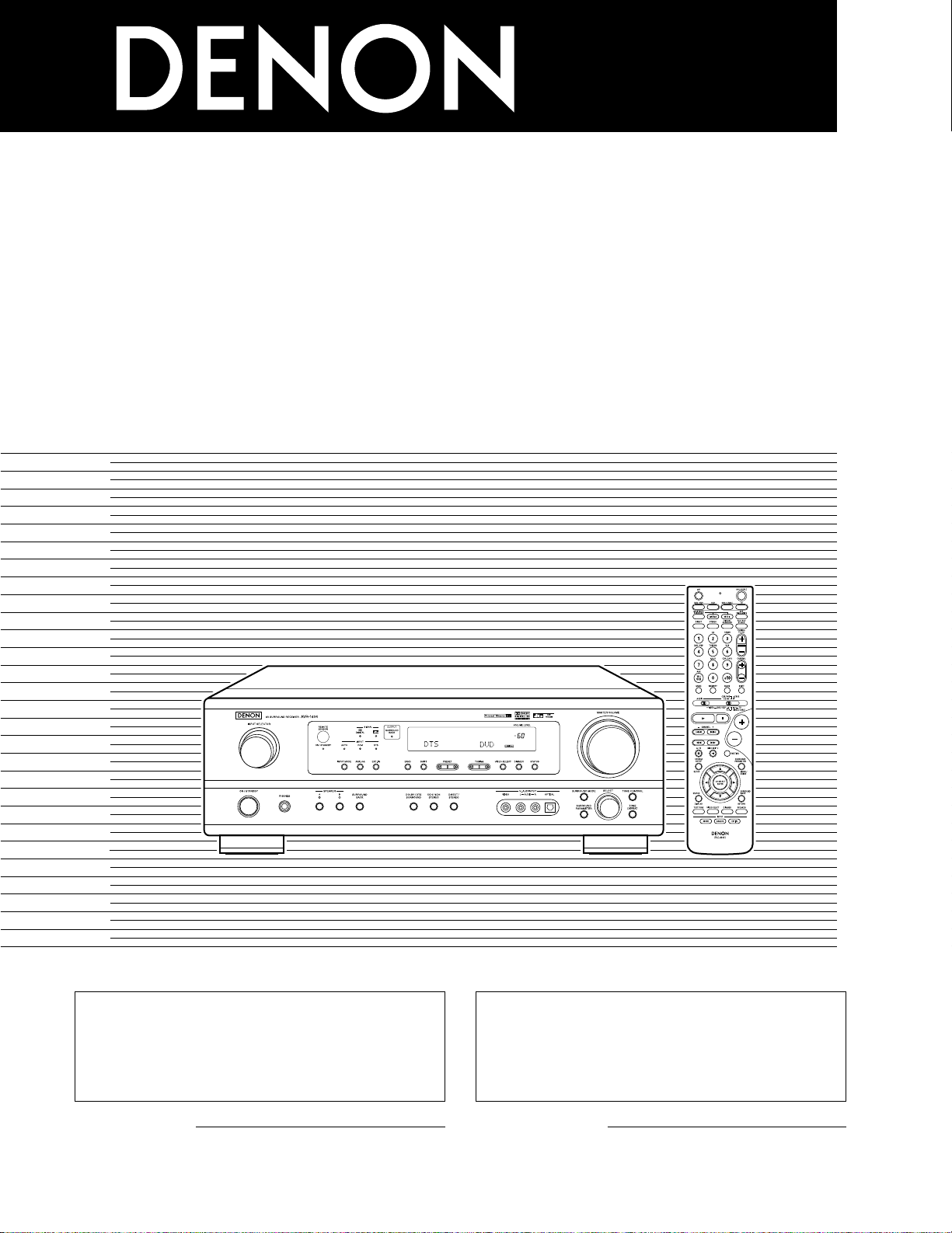
AV SURROUND RECEIVER
RÉCEPTEUR AUDIO-VIDÉO
AVR-1604/684
OPERATING INSTRUCTIONS
MODE D’EMPLOI
Page 2
2
ENGLISH
2 SAFETY PRECAUTIONS
2 NOTE ON USE / OBSERVATIONS RELATIVES A L’UTILISATION
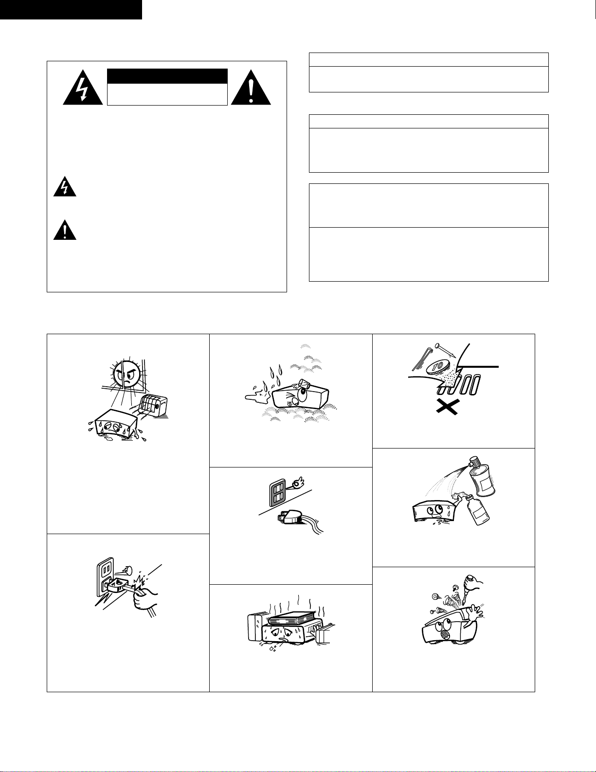
• Avoid high temperatures.
Allow for sufficient heat dispersion when
installed on a rack.
• Eviter des températures élevées.
Tenir compte d’une dispersion de chaleur
suffisante lors de l’installation sur une étagère.
• Handle the power cord carefully.
Hold the plug when unplugging the cord.
• Manipuler le cordon d’alimentation avec
précaution.
Tenir la prise lors du débranchement du
cordon.
• Keep the set free from moisture, water, and
dust.
• Protéger l’appareil contre l’humidité, l’eau et la
poussière.
• Unplug the power cord when not using the set
for long periods of time.
• Débrancher le cordon d’alimentation lorsque
l’appareil n’est pas utilisé pendant de longues
périodes.
* (For sets with ventilation holes)
• Do not obstruct the ventilation holes.
• Ne pas obstruer les trous d’aération.
• Do not let foreign objects in the set.
• Ne pas laisser des objets étrangers dans
l’appareil.
• Do not let insecticides, benzene, and thinner
come in contact with the set.
• Ne pas mettre en contact des insecticides, du
benzène et un diluant avec l’appareil.
• Never disassemble or modify the set in any
way.
• Ne jamais démonter ou modifier l’appareil
d’une manière ou d’une autre.
CAUTION: TO REDUCE THE RISK OF ELECTRIC SHOCK,
DO NOT REMOVE COVER (OR BACK). NO
USER-SERVICEABLE PARTS INSIDE. REFER
SERVICING TO QUALIFIED SERVICE
PERSONNEL.
The lightning flash with arrowhead symbol, within an
equilateral triangle, is intended to alert the user to the
presence of uninsulated “dangerous voltage” within the
product’s enclosure that may be of sufficient magnitude to
constitute a risk of electric shock to persons.
The exclamation point within an equilateral triangle is intended
to alert the user to the presence of important operating and
maintenance (servicing) instructions in the literature
accompanying the appliance.
WARNING:
TO REDUCE THE RISK OF FIRE OR ELECTRIC
SHOCK, DO NOT EXPOSE THIS APPLIANCE
TO RAIN OR MOISTURE.
CAUTION
TO PREVENT ELECTRIC SHOCK, MATCH WIDE BLADE OF PLUG
TO WIDE SLOT, FULLY INSERT.
ATTENTION
POUR ÉVITER LES CHOCS ÉLECTRIQUES, INTERODUIRE LA
LAME LA PLUS LARGE DE LA FICHE DANS LA BORNE
CORRESPONDANTE DE LA PRISE ET POUSSER JUSQU’ AU
FOND.
This device complies with Part 15 of the FCC Rules. Operation is subject to
the following two conditions: (1) This device may not cause harmful
interference, and (2) this device must accept any interference received,
including interference that may cause undesired operation.
This Class B digital apparatus meets all requirements of the Canadian
Interference-Causing Equipment Regulations.
Cet appareil numérique de la classe B respecte toutes les exigences du
Règlement sur le matériel brouilleur du Canada.
FRANCAIS
•
FOR CANADA MODEL ONLY
•
POUR LES MODELE CANADIEN UNIQUEMENT
CAUTION
RISK OF ELECTRIC SHOCK
DO NOT OPEN
Page 3

3
SAFETY INSTRUCTIONS
1. Read Instructions – All the safety and operating instructions
should be read before the product is operated.
2. Retain Instructions – The safety and operating instructions
should be retained for future reference.
3. Heed Warnings – All warnings on the product and in the
operating instructions should be adhered to.
4. Follow Instructions – All operating and use instructions should
be followed.
5. Cleaning – Unplug this product from the wall outlet before
cleaning. Do not use liquid cleaners or aerosol cleaners.
6. Attachments – Do not use attachments not recommended by
the product manufacturer as they may cause hazards.
7. Water and Moisture – Do not use this product near water – for
example, near a bath tub, wash bowl, kitchen sink, or laundry
tub; in a wet basement; or near a swimming pool; and the like.
8. Accessories – Do not place this product on an unstable cart,
stand, tripod, bracket, or table. The product may fall, causing
serious injury to a child or adult, and serious damage to the
product. Use only with a cart, stand, tripod, bracket, or table
recommended by the manufacturer, or sold with the product.
Any mounting of the product should follow the manufacturer’s
instructions, and should use a
mounting accessory
recommended by the
manufacturer.
9. A product and cart
combination should be
moved with care. Quick
stops, excessive force,
and uneven surfaces may
cause the product and cart
combination to overturn.
10. Ventilation – Slots and openings in the cabinet are provided for
ventilation and to ensure reliable operation of the product and to
protect it from overheating, and these openings must not be
blocked or covered. The openings should never be blocked by
placing the product on a bed, sofa, rug, or other similar surface.
This product should not be placed in a built-in installation such
as a bookcase or rack unless proper ventilation is provided or
the manufacturer’s instructions have been adhered to.
11. Power Sources – This product should be operated only from the
type of power source indicated on the marking label. If you are
not sure of the type of power supply to your home, consult your
product dealer or local power company. For products intended
to operate from battery power, or other sources, refer to the
operating instructions.
12. Grounding or Polarization – This product may be equipped with
a polarized alternating-current line plug (a plug having one blade
wider than the other). This plug will fit into the power outlet
only one way. This is a safety feature. If you are unable to
insert the plug fully into the outlet, try reversing the plug. If the
plug should still fail to fit, contact your electrician to replace your
obsolete outlet. Do not defeat the safety purpose of the
polarized plug.
13. Power-Cord Protection – Power-supply cords should be routed
so that they are not likely to be walked on or pinched by items
placed upon or against them, paying particular attention to
cords at plugs, convenience receptacles, and the point where
they exit from the product.
15. Outdoor Antenna Grounding – If an outside antenna or cable
system is connected to the product, be sure the antenna or
cable system is grounded so as to provide some protection
against voltage surges and built-up static charges. Article 810
of the National Electrical Code, ANSI/NFPA 70, provides
information with regard to proper grounding of the mast and
supporting structure, grounding of the lead-in wire to an
antenna discharge unit, size of grounding conductors, location
of antenna-discharge unit, connection to grounding electrodes,
and requirements for the grounding electrode. See Figure A.
16. Lightning – For added protection for this product during a
lightning storm, or when it is left unattended and unused for
long periods of time, unplug it from the wall outlet and
disconnect the antenna or cable system. This will prevent
damage to the product due to lightning and power-line surges.
17. Power Lines – An outside antenna system should not be
located in the vicinity of overhead power lines or other electric
light or power circuits, or where it can fall into such power lines
or circuits. When installing an outside antenna system,
extreme care should be taken to keep from touching such
power lines or circuits as contact with them might be fatal.
18. Overloading – Do not overload wall outlets, extension cords, or
integral convenience receptacles as this can result in a risk of
fire or electric shock.
19. Object and Liquid Entry – Never push objects of any kind into
this product through openings as they may touch dangerous
voltage points or short-out parts that could result in a fire or
electric shock. Never spill liquid of any kind on the product.
20.
Servicing – Do not attempt to service this product yourself as
opening or removing covers may expose you to dangerous
voltage or other hazards. Refer all servicing to qualified
service personnel.
21.
Damage Requiring Service – Unplug this product from the
wall outlet and refer servicing to qualified service
personnel
under the following conditions:
a) When the power-supply cord or plug is damaged,
b) If liquid has been spilled, or objects have fallen into the
product,
c) If the product has been exposed to rain or water,
d) If the product does not operate normally by following the
operating instructions. Adjust only those controls that are
covered by the operating instructions as an improper
adjustment of other controls may result in damage and will
often require extensive work by a qualified technician to
restore the product to its normal operation,
e) If the product has been dropped or damaged in any way, and
f) When the product exhibits a distinct change in performance
– this indicates a need for service.
22. Replacement Parts – When replacement parts are required, be
sure the service technician has used replacement parts
specified by the manufacturer or have the same characteristics
as the original part. Unauthorized substitutions may result in
fire, electric shock, or other hazards.
23. Safety Check – Upon completion of any service or repairs to this
product, ask the service technician to perform safety checks to
determine that the product is in proper operating condition.
24. Wall or Ceiling Mounting – The product should be mounted to a
wall or ceiling only as recommended by the manufacturer.
25. Heat – The product should be situated away from heat sources
such as radiators, heat registers, stoves, or other products
(including amplifiers) that produce heat.
FIGURE A
EXAMPLE OF ANTENNA GROUNDING
AS PER NATIONAL
ELECTRICAL CODE
ANTENNA
LEAD IN
WIRE
GROUND
CLAMP
ELECTRIC
SERVICE
EQUIPMENT
ANTENNA
DISCHARGE UNIT
(NEC SECTION 810-20)
GROUNDING CONDUCTORS
(NEC SECTION 810-21)
GROUND CLAMPS
POWER SERVICE GROUNDING
ELECTRODE SYSTEM
(NEC ART 250, PART H)
NEC - NATIONAL ELECTRICAL CODE
Page 4
4
ENGLISH
2 INTRODUCTION
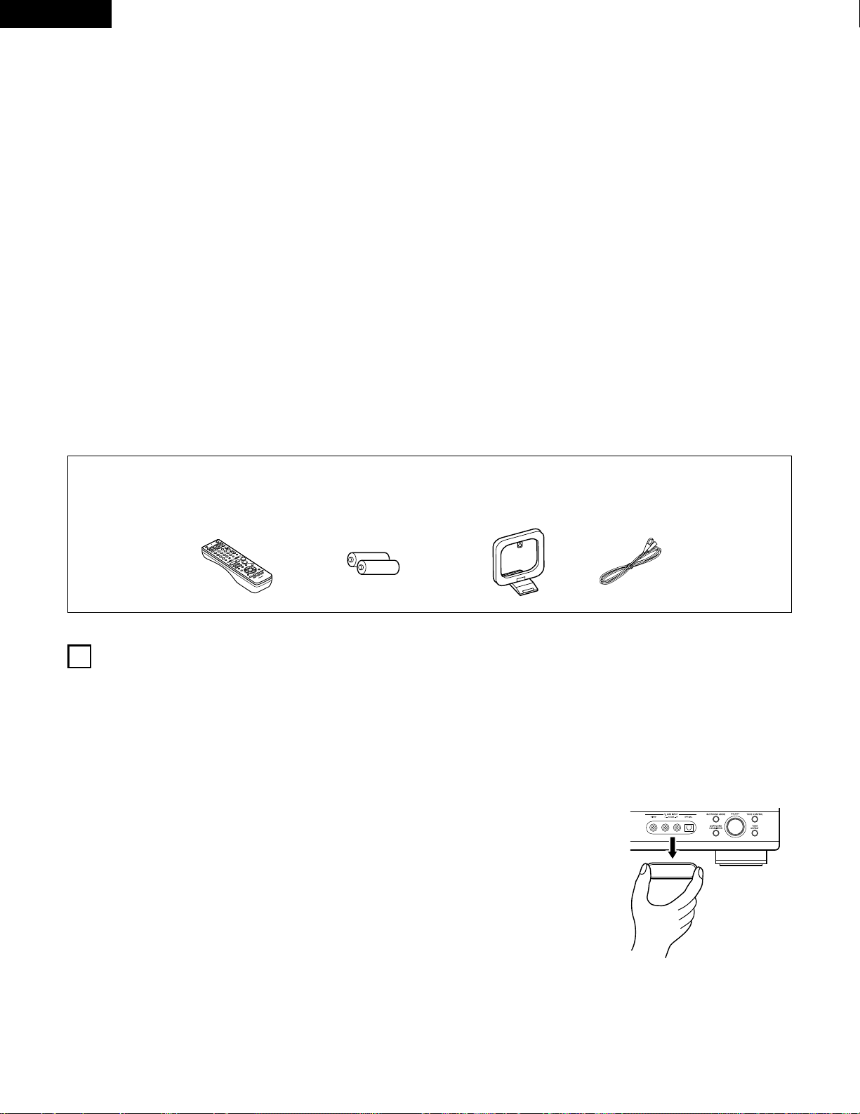
2 ACCESSORIES
Thank you for choosing the DENON A/V Surround receiver. This remarkable component has been engineered to provide superb surround sound
listening with home theater sources such as DVD, as well as providing outstanding high fidelity reproduction of your favorite music sources.
As this product is provided with an immense array of features, we recommend that before you begin hookup and operation that you review the
contents of this manual before proceeding.
TABLE OF CONTENTS
Check that the following parts are included in addition to the main unit:
1
BEFORE USING
Pay attention to the following before using this unit:
• Moving the set
T o prevent short circuits or damaged wires in the connection cords,
always unplug the power cord and disconnect the connection
cords between all other audio components when moving the set.
• Before turning the power operation switch on
Check once again that all connections are proper and that there are
not problems with the connection cords. Always set the power
operation switch to the standby position before connecting and
disconnecting connection cords.
• Store this instructions in a safe place.
After reading, store this instructions along with the warranty in a
safe place.
• Note that the illustrations in this instructions may differ from
the actual set for explanation purposes.
• V. AUX terminal
The AVR-1604/684’s front
panel is equipped with a V.
AUX terminal. Remove the
cap covering the terminal
when you want to use it.
z
Before Using ..............................................................................................4
x
Cautions on Installation..............................................................................5
c
Cautions on Handling .................................................................................5
v
Features......................................................................................................5
b
Part Names and Functions.....................................................................6, 7
n
Read this first.............................................................................................8
m
Setting up the Speaker Systems................................................................8
,
Connections.........................................................................................9~15
.
Using the Remote Control Unit................................................................16
⁄0
Setting up the System.......................................................................17~26
⁄1
Remote Control Unit..........................................................................27~31
⁄2
Operation ...........................................................................................32~36
⁄3
Surround.............................................................................................37~45
⁄4
DSP Surround Simulation...................................................................46~50
⁄5
Listening to the Radio ……………………………………………………51~53
⁄6
Last Function Memory.............................................................................54
⁄7
Initialization of the Microprocessor.…………………………………………54
⁄8
Additional Information ........................................................................55~60
⁄9
Troubleshooting........................................................................................61
¤0
Specifications .…………………………………………………………………62
List of Preset Codes..............................................................................122~126
q Operating instructions ............................................................................1
w Warranty .................................................................................................1
e Service station list...................................................................................1
r Remote control unit (RC-941).................................................................1
rt y u
t R6P/AA batteries ....................................................................................2
y AM loop antenna ....................................................................................1
u FM indoor antenna..................................................................................1
Page 5
5
ENGLISH
3
CAUTIONS ON HANDLING
4
FEATURES
• Switching the input function when input jacks are not
connected
A clicking noise may be produced if the input function is switched
when nothing is connected to the input jacks. If this happens,
either turn down the MASTER VOLUME control or connect
components to the input jacks.
• Muting of PRE OUT jack, HEADPHONE jack and SPEAKER
terminals
The PRE OUT jack, HEADPHONE jack and SPEAKER terminals
include a muting circuit. Because of this, the output signals are
greatly reduced for several seconds after the power operation
switch is turned on or input function, surround mode or any other
set-up is changed.
If the volume is turned up during this time, the output will be very
high after the muting circuit stops functioning. Always wait until
the muting circuit turns off before adjusting the volume.
• Whenever the power operation switch is in the STANDBY
state, the apparatus is still connected on some AC line
voltages.
Please be sure to unplug the cord when you leave home for,
say, a vacation.
1. Dolby Digital EX decoder system
Dolby Digital EX is a 6.1-channel surround format proposed by
Dolby Laboratories that allows users to enjoy in their homes the
“DOLBY DIGITAL SURROUND EX” audio format jointly
developed by Dolby Laboratories and Lucas Films and first used
for the movie “Star Wars Episode 1 – Phantom Menace”.
The 6.1 channels of sound, including surround back channels,
provide improved sound positioning and expression of space.
2. DTS-ES Extended Surround and DTS Neo:6
The AVR-1604/684 is compatible with DTS-ES Extended Surround, a
new multi-channel format developed by Digital Theater Systems Inc.
The AVR-1604/684 is also compatible with DTS Neo:6, a surround
mode allowing 6.1-channel playback of regular stereo sources.
3. Dolby Pro Logic II decoder
Dolby Pro Logic II is a new format for playing multichannel audio
signals that offers improvements over conventional Dolby Pro
Logic. It can be used to decode not only sources recorded in
Dolby Surround but also regular stereo sources into five channels
(front left/right, center and surround left/right). In addition, various
parameters can be set according to the type of source and the
contents, so you can adjust the sound field with greater precision.
4. Dolby Digital decoder
Using advanced digital processing algorithms, Dolby Digital
provides up to 5.1 channels of wide-range, high fidelity surround
sound. Dolby Digital is the default digital audio delivery system for
DVD and North American DTV.
5. DTS (Digital Theater Systems)
DTS provides up to 5.1 channels of wide-range, high fidelity
surround sound, from sources such as laser disc, DVD and
specially-encoded music discs.
6. Auto Surround Mode
This function stores the surround mode last used for an input
signal in the memory and automatically sets that surround mode
the next time that signal is input.
7. 6CH EXT. IN jacks
This unit is equipped with 6CH EXT. IN jacks for use with audio
formats of the future.
8. High performance DSP simulates 7 sound fields
Playback is possible in 7 surround modes: 5/6-channel Stereo,
Mono Movie, Rock Arena, Jazz Club, Video Game, Matrix and
Virtual. You can enjoy a variety of sound effects for different movie
scenes and program sources even with stereo sources not in
Dolby Surround.
9. Personal Memory Plus function
Personal Memory Plus is an advanced version of Personal
Memory. With Personal Memory Plus, the set automatically
memorizes the surround mode, channel volume, surround
parameters, etc., for each of the separate input sources.
2
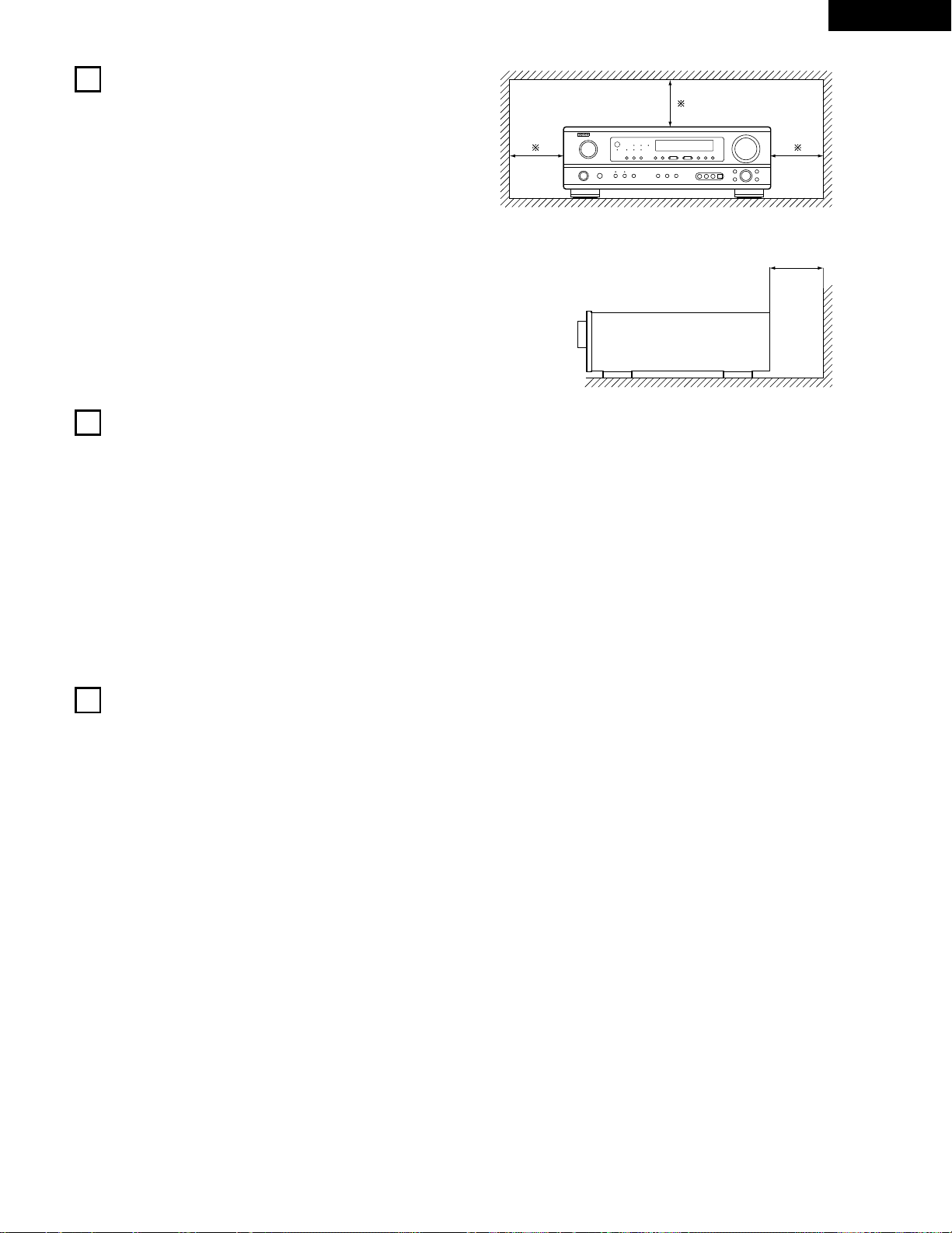
CAUTIONS ON INSTALLATION
Noise or disturbance of the picture may be generated if this unit or
any other electronic equipment using microprocessors is used near a
tuner or TV.
If this happens, take the following steps:
• Install this unit as far as possible from the tuner or TV.
• Set the antenna wires from the tuner or TV away from this unit’s
power cord and input/output connection cords.
• Noise or disturbance tends to occur particularly when using indoor
antennas or 300 Ω/ohms feeder wires. We recommend using
outdoor antennas and 75 Ω/ohms coaxial cables.
For heat dispersal, leave at least 0.3 ft (10 cm) of space between
the top, back and sides of this unit and the wall or other
components.
0.3 ft (10 cm) or more
wall
0.3 ft (10 cm) or more
Page 6
6
ENGLISH
5
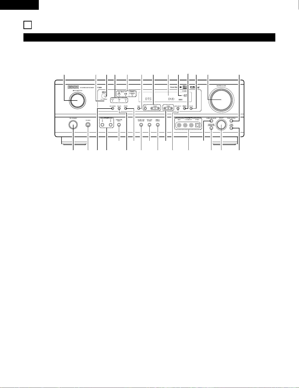
PART NAMES AND FUNCTIONS
Front Panel
• For details on the functions of these parts, refer to the pages given in parentheses ( ).
q wue ir
y
o!4t !1
@1@2
@3@4@5@6@7@8@9
!2 !3 !5 !6 !7!0
!8@0 !9#0
q
Power operation switch ..............................................(18, 32, 51)
w
Headphones jack (PHONES)....................................................(35)
e
INPUT MODE button...................................................(33, 36, 43)
r
SPEAKER A/B buttons.......................................................(32, 54)
t
SURROUND BACK button ......................................................(43)
y
ANALOG button ................................................................(33, 36)
u
EXT. IN button ...................................................................(33, 36)
i
DOLBY/DTS SURROUND button................................(37, 39, 43)
o
5CH/6CH STEREO button .................................................(46, 49)
!0
DIRECT/STEREO button..........................................................(46)
!1
TUNING D (up) / H (down) buttons.........................................(52)
!2
VIDEO SELECT button ............................................................(35)
!3
V. AUX terminals..................................................................(4, 11)
!4
SURROUND MODE button...............................................(34, 49)
!5
SURROUND PARAMETER button.....................................(39, 47)
!6
SELECT knob...............................................................(34, 39, 49)
!7
TONE DEFEAT button.............................................................(34)
!8
TONE CONTROL button..........................................................(34)
!9
MASTER VOLUME control ......................................................(34)
@0
STATUS button ........................................................................(35)
@1
DIMMER button ......................................................................(35)
@2
Master volume indicator (VOLUME LEVEL) ............................(34)
@3
Display
@4
Preset station select buttons ............................................(51, 53)
@5
BAND button ...........................................................................(52)
@6
SIGNAL indicators....................................................................(34)
@7
INPUT mode indicators............................................................(34)
@8
Remote control sensor (REMOTE SENSOR) ..........................(16)
@9
Power operation indicator (ON/STANDBY)
#0
INPUT SELECTOR knob..........................................................(33)
Page 7
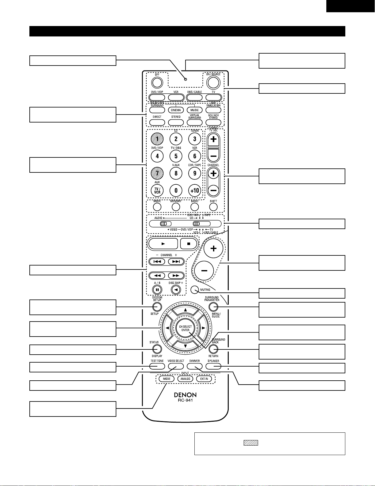
NOTE:
• The shaded buttons do not function with the AVR-1604/684.
(Nothing happens when they are pressed.)
7
ENGLISH
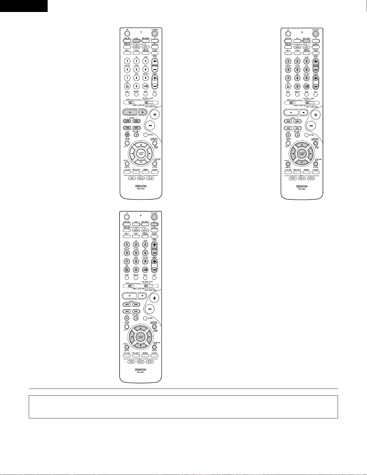
Remote control unit
• For details on the functions of these parts, refer to the pages given in parentheses ( ).
SURROUND
buttons...................................(34, 37, 47)
Cursor
buttons.............................(17, 29, 37, 47)
STATUS/DISPLAY button.............(29, 35)
Test tone button.................................(37)
Remote control signal
transmitter .........................................(16)
Master volume control
buttons...............................................(34)
POWER buttons..............(18, 28~30, 32)
MUTING button .................................(35)
Mode selector switches..(17, 27~29, 31)
Tuner system/
System buttons ...............(27, 30, 52, 53)
SYSTEM SET UP/
SETUP button........................(17, 26, 29)
INPUT MODE selector
buttons.........................................(33, 36)
Input source selector
buttons ............................(28~31, 33, 39)
SURROUND PARAMETER
button...........................................(29, 39)
CH SELECT (channel select)/
ENTER button ..................(17, 29, 38, 40)
SURROUND BACK/
RETURN button ...........................(29, 43)
SPEAKER select button.....................(32)
DIMMER button.................................(35)VIDEO SELECT button.......................(35)
System buttons .....................(27, 29, 30)
LED (indicator) .............................(28, 31)
Page 8
8
ENGLISH
6
READ THIS FIRST
This AV Surround Receiver must be setup before use. Following these steps.
7
SETTING UP THE SPEAKER SYSTEMS
Step 3 (page 17 to 26)
Finally, setting up the system.
Step 2 (page 16)
Next, insert the batteries into the remote control unit.
Step 1 (page 8 to 15)
Choose the best location to setup the Speakers and connecting the components.
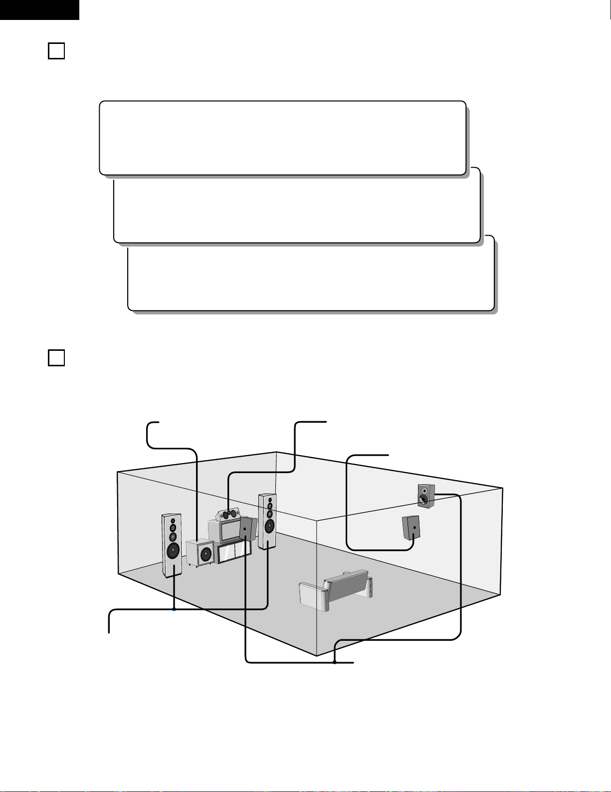
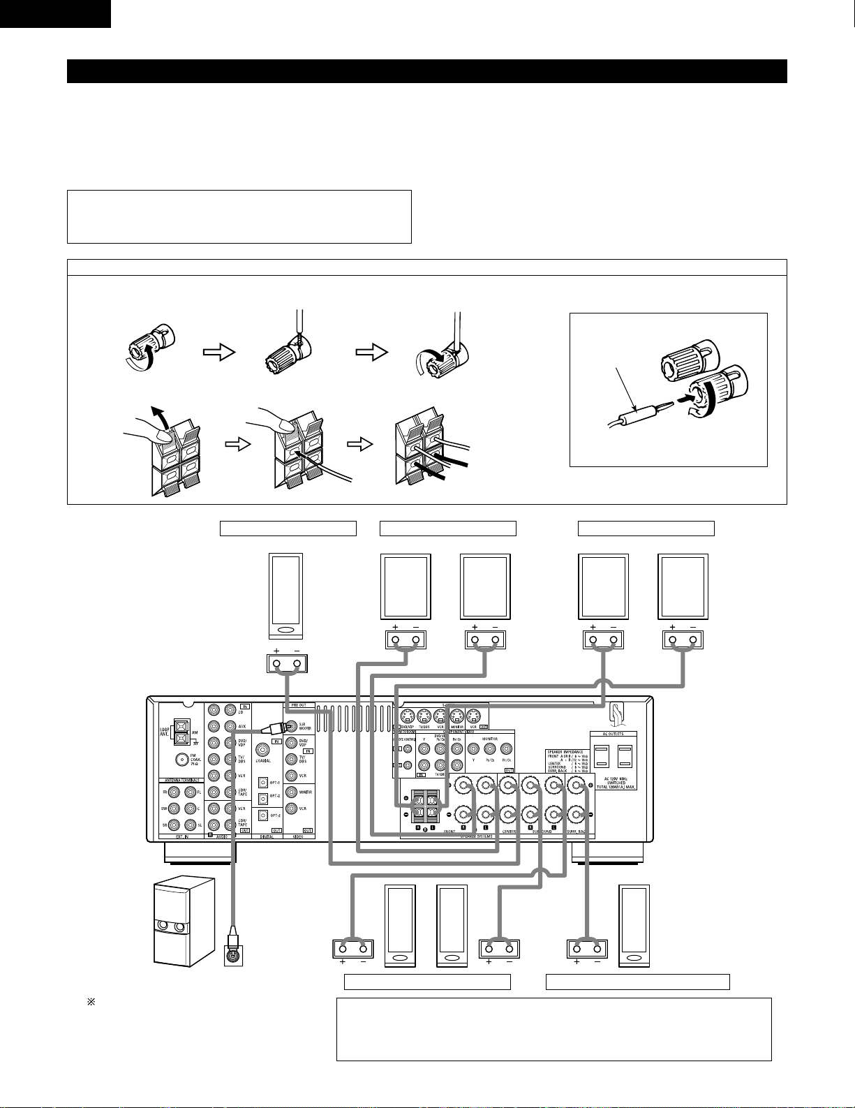
2 Speaker system layout
Basic system layout
• The following is an example of the basic layout for a system consisting of seven speaker systems and a television monitor:
Subwoofer Center speaker system
Surround speaker systems
Surround back speaker system
Front speaker systems
Set these at the sides of the TV or screen with
their front surfaces as flush with the front of the
screen as possible.
Page 9
9
ENGLISH
8
CONNECTIONS
• Do not plug in the power cord until all connections have been
completed.
• Be sure to connect the left and right channels properly (left with
left, right with right).
• Insert the plugs securely. Incomplete connections will result in
the generation of noise.
• Use the AC OUTLETS for audio equipment only. Do not
use them for hair driers, etc.
• Note that binding pin plug cords together with power cords or
placing them near a power transformer will result in generating
hum or other noise.
• Noise or humming may be generated if a connected audio
equipment is used independently without turning the power
of this unit on. If this happens, turn on the power of the this
unit.
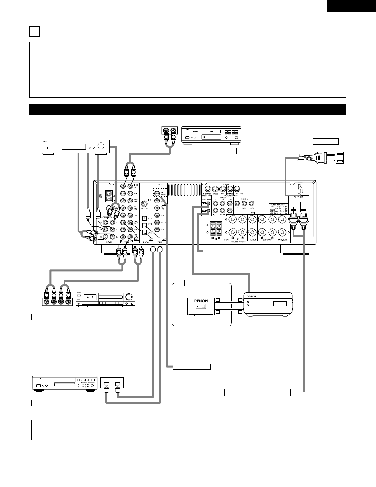
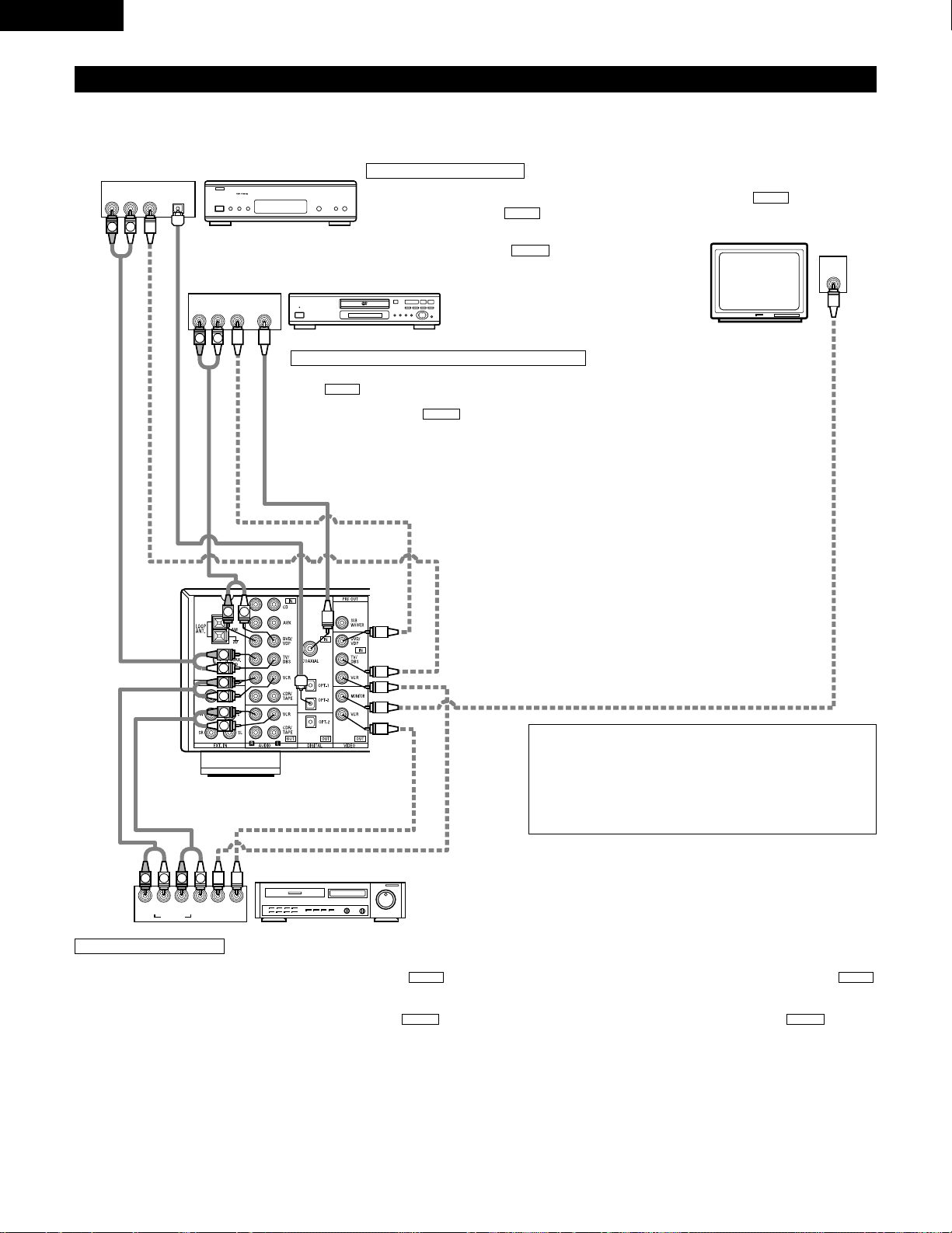
Connecting the audio components
LINE OUT
SURROUND
SUB WOOFER
CENTER
FRONT
LINE OUT
LINE OUT
LINE IN
R
OUTPUTINPUT
LRL
R
OUTPUT
L
R
L
R
L
R
L
L
R
L
R
R
L
R
L
L
R
DIGITAL AUDIODIGITAL AUDIO
INPUTOUTPUT
OPTICAL
B
++
INPUT
OUTPUT
AUX OUT
Connecting a CD player
Connect the CD player’s analog output jacks
(ANALOG OUTPUT) to this unit’s CD jacks using
pin plug cords.
Decoders with 6-channel
analog outputs, etc.
DIGITAL jacks
Use these for connections to audio equipment with digital output.
Refer to Page 25 for instructions on setting this terminal.
Connecting the AC OUTLETS
AC OUTLETS
• SWITCHED
(total capacity – 120 W (1 A.))
The power to these outlets is turned on and off in conjunction with the POWER switch
on the main unit, and when the power is switched between on and standby from the
remote control unit.
No power is supplied from these outlets when this unit’s power is at standby. Never
connect equipment whose total capacity is above 120 W (1 A.)
NOTE:
Only use the AC OUTLETS for audio equipment. Never use them for hair driers, TVs or
other electrical appliances.
AC CORD
AC 120V, 60Hz
Connect the internal amplifier’s subwoofer to the subwoofer
terminal. (Refer to page 14.)
Connecting a tape deck
Connections for recording:
Connect the tape deck’s recording input jacks (LINE IN or
REC) to this unit’s tape recording (OUT) jacks using pin plug
cords.
Connections for playback:
Connect the tape deck’s playback output jacks (LINE OUT or
PB) to this unit’s tape playback (IN) jacks using pin plug cords.
CD player
Tape deck or CD recorder
• Use 75 Ω/ohms cable pin cords (sold separately) for coaxial
connections.
• Use optical cables (sold separately) for optical connections.
Subwoofer jack
CD recorder, MD recorder or other component
equipped with digital output jacks.
• When a sold separately room-to-room remote control unit
(DENON RC-616, 617 or 618) is wired and connected between
the MAIN ROOM and ANOTHER ROOM, the remotecontrollable devices in the main room can be controlled from
ANOTHER ROOM using the remote control unit.
Another room
RC-617 (Sold Separately)
Infrared sensor
RC-616
(Sold Separately)
Infrared retransmitter
Extension jacks for future use.
Page 10
10
ENGLISH
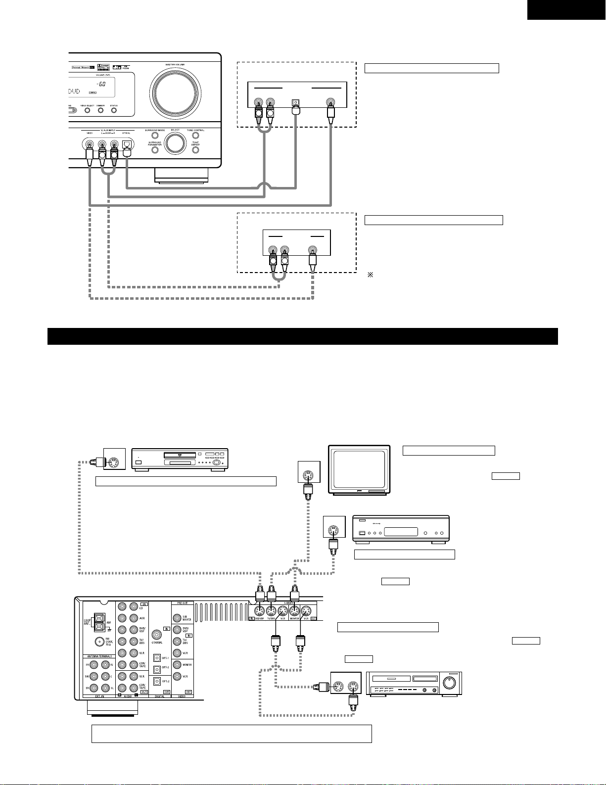
Connecting the video equipments
To connect the video signal, connect using a 75 Ω/ohms video signal cable cord. Using an improper cable can result in a drop in sound quality.
IN
VIDEO
R
L
R
L
R
L
L
R
R OUT IN
AUDIO
VIDEO
OUT IN
LRL
R
L
R
L
R OUT
VIDEO
OUT
L
AUDIO
OUT
COAXIAL
DIGITAL
L
R
R OUT
VIDEO
OPTICAL
OUT
L
AUDIO
OUT
DIGITAL
L
R
B
B
TV or DBS tuner
DVD player or VDP
Monitor TV
Connecting a TV/DBS tuner
TV/DBS
• Connect the TV’s or DBS tuner’s video output jack
(VIDEO OUTPUT) to the (yellow) TV/DBS IN
jack using a 75 Ω/ohms video coaxial pin plug cord.
• Connect the TV’s or DBS tuner’s audio output jacks
(AUDIO OUTPUT) to the TV/DBS IN jacks
using pin plug cords.
AUDIO
VIDEO
Connecting a DVD player or a video disc player (VDP)
• Connect the DVD player’s (video disc player’s) video output jack (VIDEO OUTPUT) to
the (yellow) DVD/VDP IN jack using a 75 Ω/ohms video coaxial pin plug cord.
• Connect the DVD player’s (video disc player’s) analog audio output jacks (ANALOG
AUDIO OUTPUT) to the DVD/VDP IN jacks using pin plug cords.
• For better sound quality, we recommend using the DVD player with digital rather than
analog connections.
DVD and VDP players can also be connected to the VCR terminals.
AUDIO
VIDEO
MONITOR OUT
• Connect the TV’s video input jack (VIDEO
INPUT) to the MONITOR OUT
jack using a 75 Ω/ohms video coaxial pin
plug cord.
VIDEO
NOTE:
Connection of the video disc Player Equipped with Dolby Digital RF
Output Jack.
• Please use a commercially available adaptor when connecting the
Dolby Digital RF output jack of the video disc player to the digital
input jack.
Please refer to the instruction manual of the adapter when making
connections.
Video deck
Video input/output connections:
• Connect the video deck’s video output jack (VIDEO OUT) to the (yellow) VCR IN jack, and the video deck’s video input jack (VIDEO IN) to the
(yellow) VCR OUT jack using 75 Ω/ohms video coaxial pin plug cords.
Connecting the audio output jacks:
• Connect the video deck’s audio output jacks (AUDIO OUT) to the VCR IN jacks, and the video deck’s audio input jacks (AUDIO IN) to the VCR OUT
jacks using pin plug cords.
AUDIOAUDIO
VIDEOVIDEO
Connecting a video decks
VIDEO OUT
VIDEO IN
VIDEO IN
AUDIO OUT
VIDEO OUT
VIDEO OUT
AUDIO OUT
AUDIO OUT
AUDIO IN
Page 11
11
ENGLISH
Connecting a video component equipped with S-video jacks
• When marking connections, also refer to the operating instructions of the other components.
• A note on the S input jacks
The input selectors for the S inputs and pin jack inputs work in conjunction with each other.
• Precaution when using S-jacks
This unit’s S-jacks (input and output) and video pin jacks (input and output) have independent circuit structures, so that video signals input from
the S-jacks are only output from the S-jack outputs and video signals input from the pin jacks are only output from the pin jack outputs.
When connecting this unit with equipment that is equipped with S-jacks, keep the above point in mind and make connections according to the
equipment’s instruction manuals.
IN
S-VIDEO
OUT
S-VIDEO
OUT
S-VIDEO
OUT IN
S-VIDEO
VIDEO IN
VIDEO OUT
VIDEO IN
VIDEO OUT
VIDEO OUT
B
B
DVD player, VDP, etc.
Connecting a DVD player or video disc player (VDP)
DVD/VDP
• Connect the DVD player’s or video disc player’s SVideo output jack to the S-VIDEO DVD/VDP IN jack
using an S-Video connection cord.
Connecting a monitor TV
MONITOR OUT
• Connect the TV’s or DBS tuner’s S video input
(S-VIDEO INPUT) to the MONITOR
OUT jack using a S jack connection cord.
S-VIDEO
Monitor TV
Connecting a TV/DBS tuner
• Connect the TV’s or DBS tuner’s S
video output jack (S-VIDEO OUTPUT)
to the TV/DBS IN jack using
an S jack connection cord.
S-VIDEO
TV or satellite broadcast tuner
Video deck
Connecting the video decks
• Connect the video deck’s S output jack (S-OUT) to the
VCR IN jack and the video deck’s S input jack (S-IN) to the
VCR OUT jack using S jack connection cords.
S-VIDEO
S-VIDEO
Connect the components’ audio inputs and outputs as described on page 10.
R VIDEO OUTOPTICALL
R VIDEO OUTL
OUTPUT
OUTPUT
LINE OUT
DIGITAL OUT
VIDEO OUT
VIDEO OUT
LINE OUT
L
R
L
R
L
R
Connecting a Video game equipment
• Connect the Video game equipment’s output jacks to this
unit’s V. AUX INPUT jacks.
Video game
Video camera
Connecting a Video camera equipment
• Connect the video camera equipment’s output jacks to this
unit’s V. AUX INPUT jacks.
The V. AUX terminal is covered with a cap. Remove this
cap in order to use the terminal. (See page 4 for instructions
on removing the cap.)
Page 12
12
ENGLISH
VIDEO OUT
Y
CRCB
COMPONENT
YCRCB
VIDEO IN
COMPONENT
B
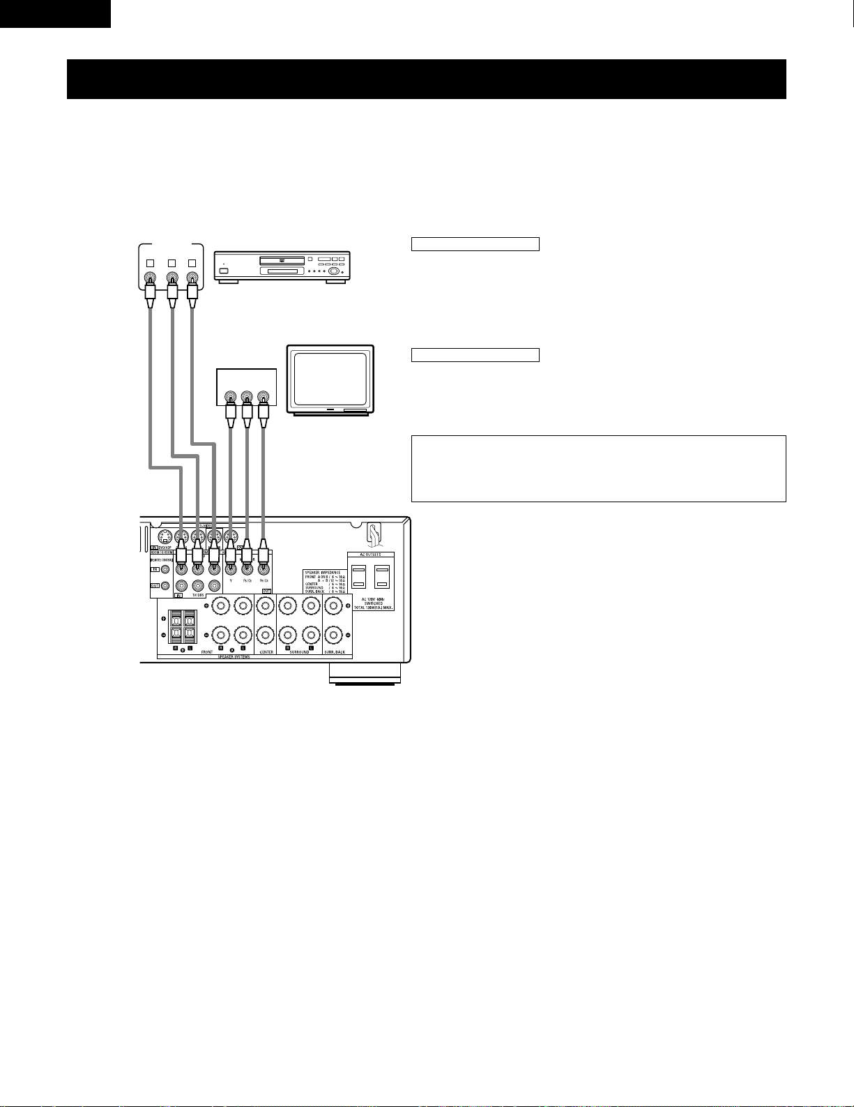
Connecting a Video Component Equipped with Color Difference (Component - Y, PR/CR,
P
B/CB
) Video Jacks (DVD Player)
• When making connections, also refer to the operating instructions of the other components.
• The signals input to the color difference (component) video jacks are not output from the VIDEO output jack (yellow) or the S-Video output jack.
In addition, the video signals input to the VIDEO input (yellow) and S-Video input jacks are not output to the color difference (component) video
jacks.
• Some video sources with component video outputs are labeled Y, C
B, CR, or Y, Pb, Pr, or Y, R-Y, B-Y. These terms all refer to component video
color difference output.
DVD player
Connecting a DVD player
DVD IN jacks
• Connect the DVD player’s color difference (component) video output jacks
(COMPONENT VIDEO OUTPUT) to the COMPONENT DVD IN jack using 75 Ω/ohms
coaxial video pin-plug cords.
• In the same way, another video source with component video outputs such as a
TV/DBS tuner, etc., can be connected to the TV/DBS color difference (component)
video jacks.
Monitor TV
Connecting a monitor TV
MONITOR OUT jack
• Connect the TV’s color difference (component) video input jacks (COMPONENT
VIDEO INPUT) to the COMPONENT MONITOR OUT jack using 75 Ω/ohms coaxial
video pin-plug cords.
• The color difference input jacks may be indicated differently on some
TVs, monitors or video components (“C
R, CB
and Y”, “R-Y, B-Y and Y”,
“Pr, Pb and Y”, etc.). For details, carefully read the operating
instructions included with the TV or other component.
Page 13
13
ENGLISH
1
4
2
3
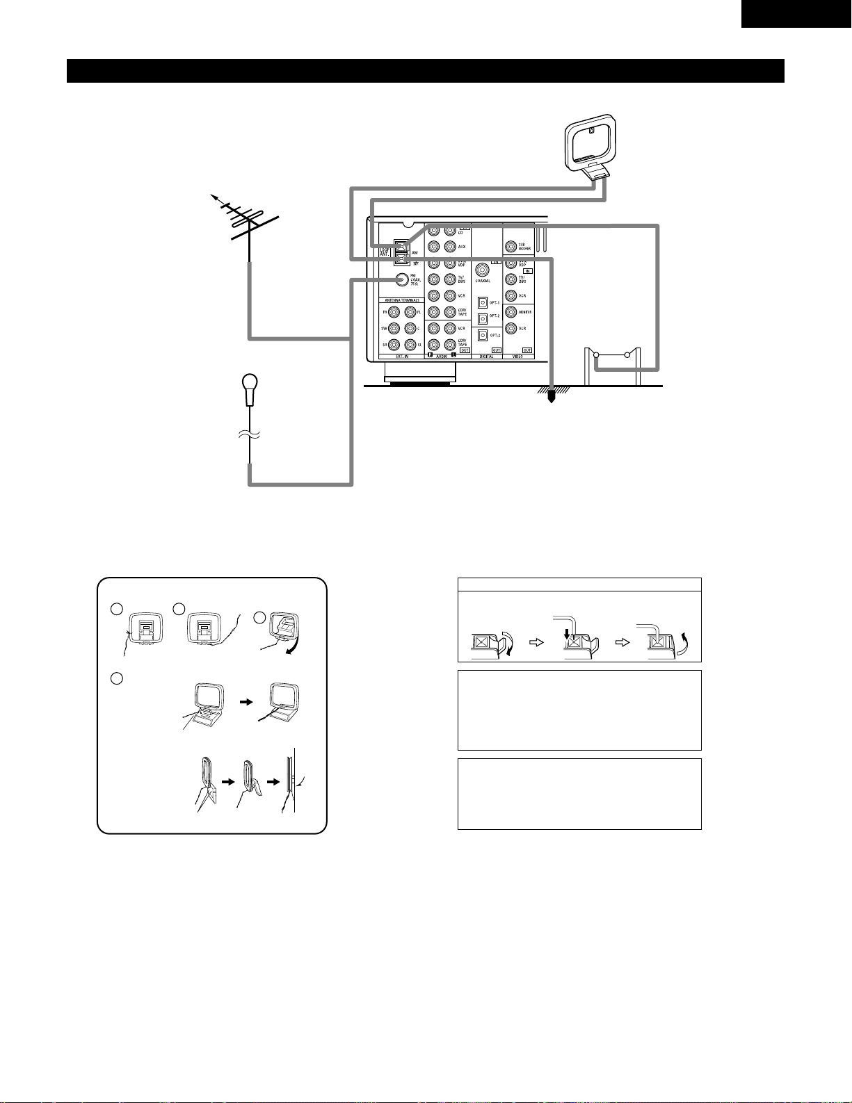
Connecting the antenna terminals
DIRECTION OF
BROADCASTING
STATION
AM LOOP
ANTENNA
(An Accessory)
FM ANTENNA
GROUND
AM OUTDOOR
ANTENNA
FM INDOOR ANTENNA
(An Accessory)
75 Ω/ohms
COAXIAL
CABLE
AM loop antenna assembly
Connect to the AM
antenna terminals.
Bend in the reverse
direction.
Remove the vinyl tie
and take out the
connection line.
a. With the antenna
on top any stable
surface.
b. With the antenna
attached to a
wall.
Mount
Installation hole
Mount on wall, etc.
Connection of AM antennas
1. Push the lever. 2. Insert the
conductor.
3. Return the lever.
Note to CATV system installer:
This reminder is provided to call the CATV system installer’s
attention to Article 820-40 of the NEC which provides
guidelines for proper grounding and, in particular, specifies
that the cable ground shall be connected to the grounding
system of the building, as close to the point of cable entry as
practical.
Notes:
• Do not connect two FM antennas simultaneously.
• Even if an external AM antenna is used, do not disconnect
the AM loop antenna.
• Make sure AM loop antenna lead terminals do not touch
metal parts of the panel.
Page 14
14
ENGLISH
Speaker system connections
• Connect the speaker terminals with the speakers making sure that like
polarities are matched (< with <, > with >). Mismatching of polarities will
result in weak central sound, unclear orientation of the various instruments,
and the sense of direction of the stereo being impaired.
• When making connections, take care that none of the individual conductors
of the speaker cord come in contact with adjacent terminals, with other
speaker cord conductors, or with the rear panel.
Speaker Impedance
• When speaker systems A and B are use separately, speakers with an
impedance of 6 to 16 Ω/ohms can be connected for use as front speakers.
• Be careful when using two pairs of front speakers (A + B) at the same time,
since use of speakers with an impedance of 12 to 16 Ω/ohms.
• Speakers with an impedance of 6 to 16 Ω/ohms can be connected for use
as center and surround and surround back speakers.
• The protector circuit may be activated if the set is played for long periods of
time at high volumes when speakers with an impedance lower than the
specified impedance are connected.
NOTE:
NEVER touch the speaker terminals when the power is on.
Doing so could result in electric shocks.
Connecting the speaker cords
1. Loosen by turning
counterclockwise.
2. Insert the cord. 3. Tighten by turning
clockwise.
Connecting banana plugs
Turn clockwise to tighten, then insert the
banana plug.
banana plug
1. Push the lever. 2. Insert the cord. 3. Return the lever.
(L)(R)
(L) (R)(L) (R)
Connection jack for subwoofer with built-in amplifier
(super woofer), etc.
To achieve Dolby Digital playback effect, use a unit
that can sufficiently reproduce frequencies of
under 80 Hz.
SURROUND SPEAKER SYSTEMS
CENTER SPEAKER SYSTEM FRONT SPEAKER SYSTEMS
• Precautions when connecting speakers
If a speaker is placed near a TV or video monitor, the colors on the screen may be disturbed by
the speaker’s magnetism. If this should happen, move the speaker away to a position where
it does not have this effect.
System B
FRONT SPEAKER SYSTEMS
System A
SURROUND BACK SPEAKER SYSTEM
Page 15
15
ENGLISH
Protector circuit
• This unit is equipped with a high-speed protection circuit. The purpose of this circuit is to protect the speakers under
circumstances such as when the output of the power amplifier is inadvertently short-circuited and a large current flows,
when the temperature surrounding the unit becomes unusually high, or when the unit is used at high output over a long
period which results in an extreme temperature rise.
When the protection circuit is activated, the speaker output is cut off and the power supply indicator LED flashes. Should
this occur , please follow these steps: be sure to switch off the power of this unit, check whether there are any faults with
the wiring of the speaker cables or input cables, and wait for the unit to cool down if it is very hot. Improve the ventilation
condition around the unit and switch the power back on.
If the protection circuit is activated again even though there are no problems with the wiring or the ventilation around the
unit, switch off the power and contact a DENON service center.
Note on speaker impedance
• The protector circuit may be activated if the set is played for long periods of time at high volumes when speakers with
an impedance lower than the specified impedance (for example speakers with an impedance of lower than 4 Ω/ohms)
are connected. If the protector circuit is activated, the speaker output is cut off. Turn off the set’s power, wait for the set
to cool down, improve the ventilation around the set, then turn the power back on.
Page 16
16
ENGLISH
9
USING THE REMOTE CONTROL UNIT
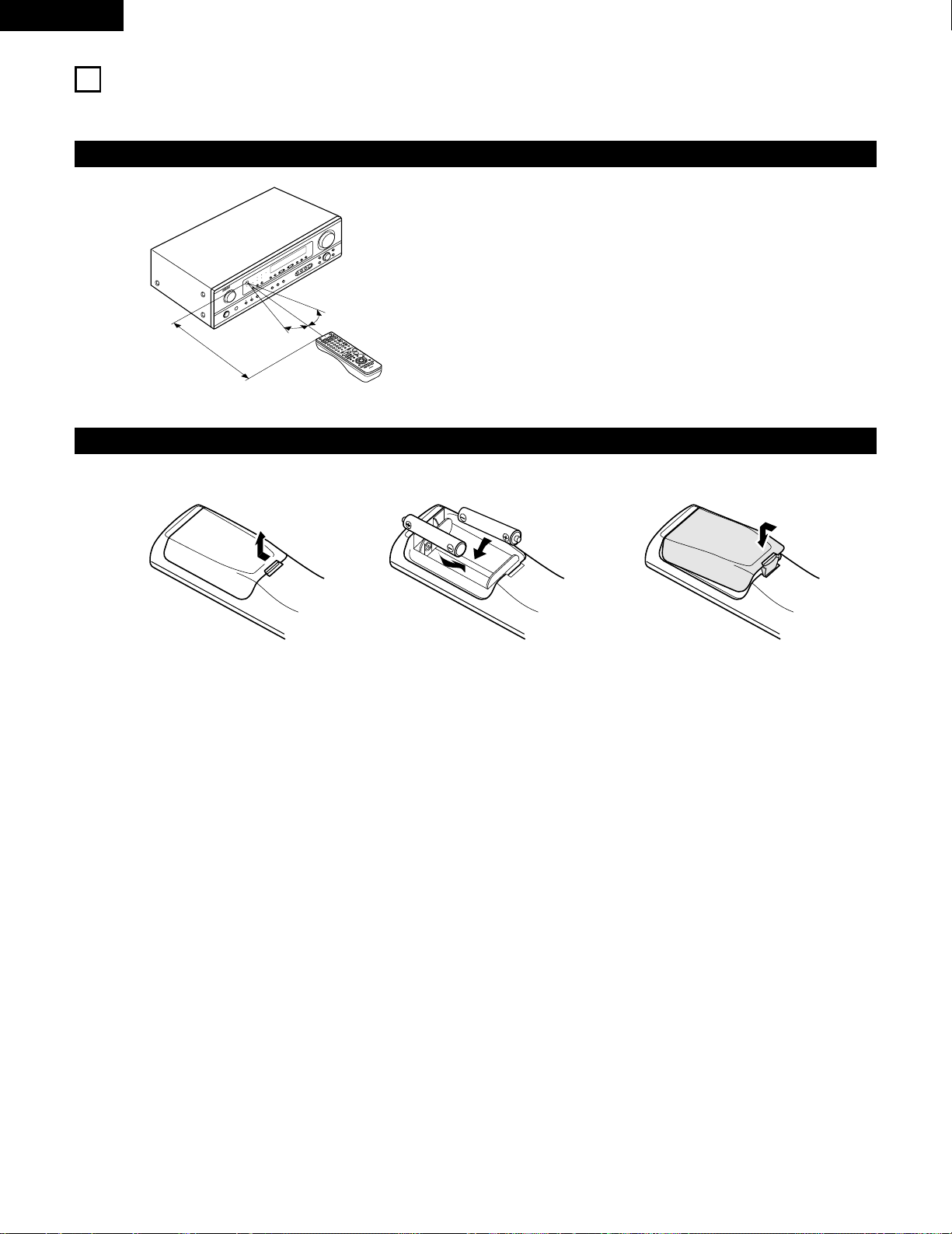
Following the procedure outlined below, insert the batteries before using the remote control unit.
Range of operation of the remote control unit
Inserting the batteries
Point the remote control unit at the remote control sensor as shown
on the diagram at the left.
NOTES:
• The remote control unit can be used from a straight distance of
approximately 23 feet/7 meters, but this distance will shorten or
operation will become difficult if there are obstacles between the
remote control unit and the remote control sensor, if the remote
control sensor is exposed to direct sunlight or other strong light, or
if operated from an angle.
• Neon signs or other devices emitting pulse-type noise nearby may
result in malfunction, so keep the set as far away from such
devices as possible.
Approx. 23 feet/7 m
30°
30°
w Insert the R6P/AA batteries properly, as
shown on the diagram.
q Press as shown by the arrow and slide
off.
e Close the lid.
NOTES:
• Use only R6P/AA batteries for replacement.
• Be sure the polarities are correct. (See the illustration inside the battery compartment.)
• Remove the batteries if the remote control transmitter will not be used for an extended period of time.
• If batteries leak, dispose of them immediately. Avoid touching the leaked material or letting it come in contact with clothing, etc. Clean the
battery compartment thoroughly before installing new batteries.
• Have replacement batteries on hand so that the old batteries can be replaced as quickly as possible when the time comes.
• Even if less than a year has passed, replace the batteries with new ones if the set does not operate even when the remote control unit is
operated nearby the set. (The included battery is only for verifying operation. Replace it with a new battery as soon as possible.)
Page 17
17
ENGLISH
10
SETTING UP THE SYSTEM
• Once all connections with other A V components have been completed as described in “CONNECTIONS” (see pages 9 to 15), make the various
settings described below on the display.
These settings are required to set up the listening room’s AV system centered around the this unit.
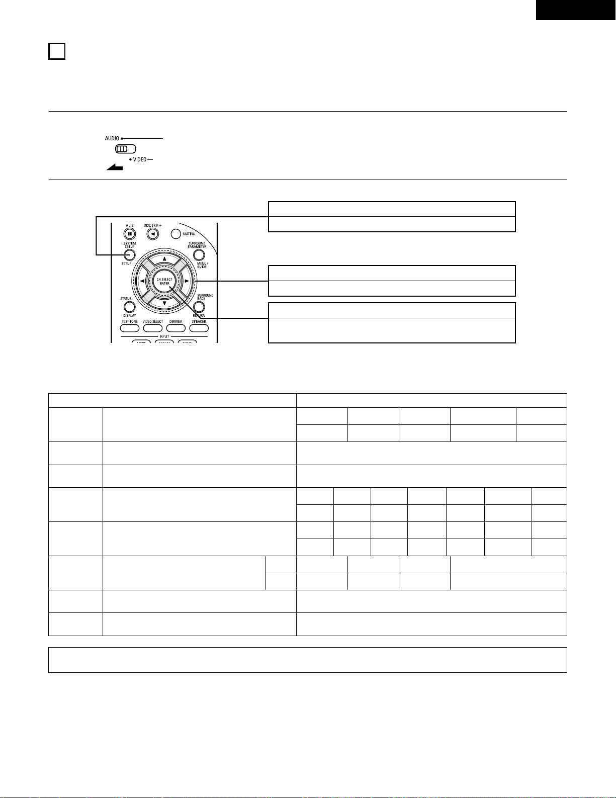
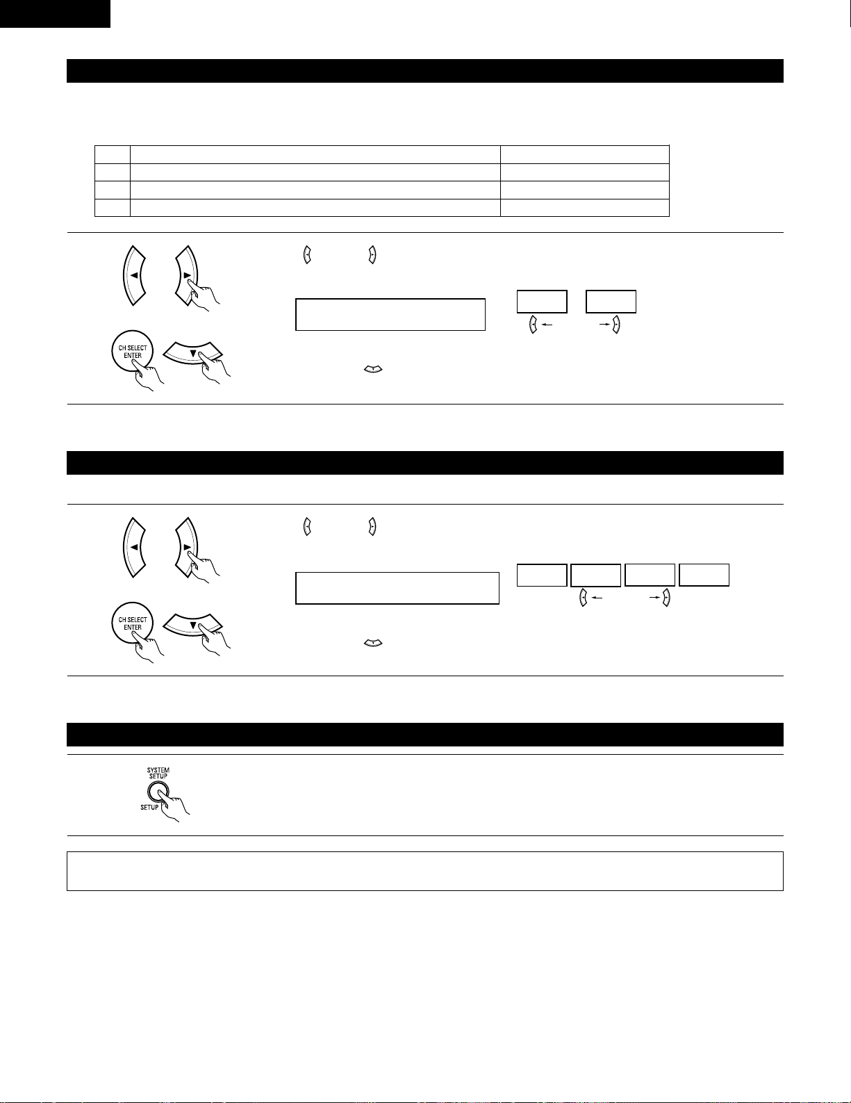
SYSTEM SETUP button
Press this to display the system setup on the display.
CURSOR buttons (•, ª, 0, 1)
Press this change what appears on the display.
ENTER button
Press this to switch the display.
Also use this button to complete the setting.
• System setup items and default values (set upon shipment from the factory)
System setup Default settings
Speaker
Configuration
Subwoofer Mode
Digital In
Assignment
Input the combination of speakers in your system and their
corresponding sizes (SMALL for regular speakers, LARGE for full-size,
full-range) to automatically set the composition of the signals output
from the speakers and the frequency response.
This assigns the digital input jacks for the different input
sources.
Input
source
Digital
Inputs
Front Sp.
Large
Center Sp. Surround Sp. Subwoofer
Small Small Yes
CD DVD/VDP
COAXIAL OPTICAL 1
Delay Time
This parameter is for optimizing the timing with which the audio
signals are produced from the speakers and subwoofer according to
the listening position.
1
Set the slide switch to “AUDIO”.
2
Use the following buttons to set up the system:
This selects the subwoofer speaker for playing deep bass signals. Subwoofer mode = Normal
NOTE:
• The system setup is not displayed when “HEADPHONE ONLY” is selected.
Crossover
Frequency
Set the frequency (Hz) below which the bass sound of the various
speakers is to be output from the subwoofer.
80 Hz
Auto Surround
Mode
Auto surround mode function setting. Auto Surround Mode = ON
Ext. In SW Level Set the Ext. In Subwoofer channel playback level. Ext. In SW Level = +15 dB
TV/DBS
OPTICAL 2
Surround back Sp.
Small
Front L Center Surround Back
12 ft 12 ft 10 ft
Subwoofer
12 ft
Front R
12 ft
Surround L
10 ft
Surround R
10 ft
Front L Front R Center
0 dB 0 dB 0 dB
Test Tone
This adjusts the volume of the signals output from the speakers and
subwoofer for the different channels in order to obtain optimum
effects.
Surround L
0 dB
Surround R
0 dB
Surround Back
0 dB
Subwoofer
0 dB
Page 18
18
ENGLISH
Before setting up the system
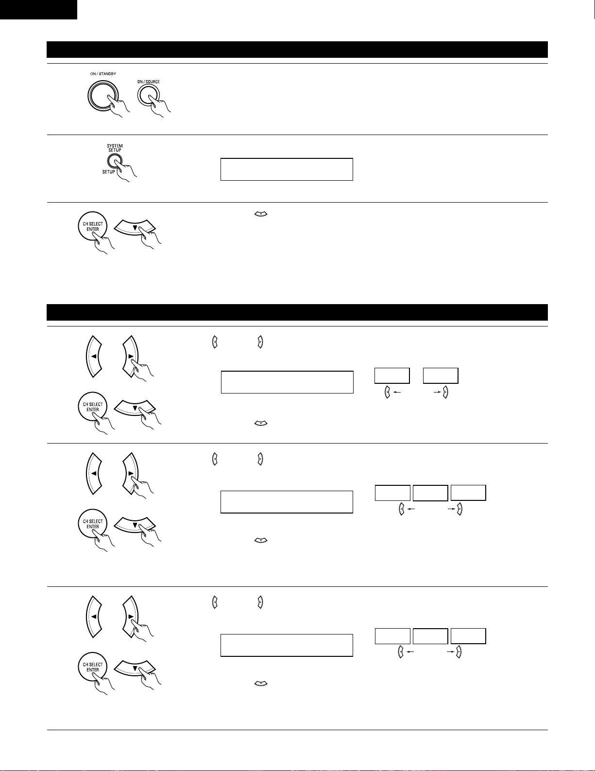
1
2
Press the SYSTEM SETUP button to enter the setting.
Check that all the components are correct, then press the POWER operation switch on the main unit or
the POWER button on the remote control unit to turn on the power.
3
Press the ENTER or (down) button to switch to the speaker configuration set up.
*SYSTEM SET UP
NOTE:
Press the SYSTEM SETUP button again to finish system set up. System set up can be finished at any time. The changes to the settings
made up to that point are entered.
NOTE: Please make sure the “AUDIO” position of the slide switch on the remote control unit.
(Main unit) (Remote control unit)
Setting the speaker configuration
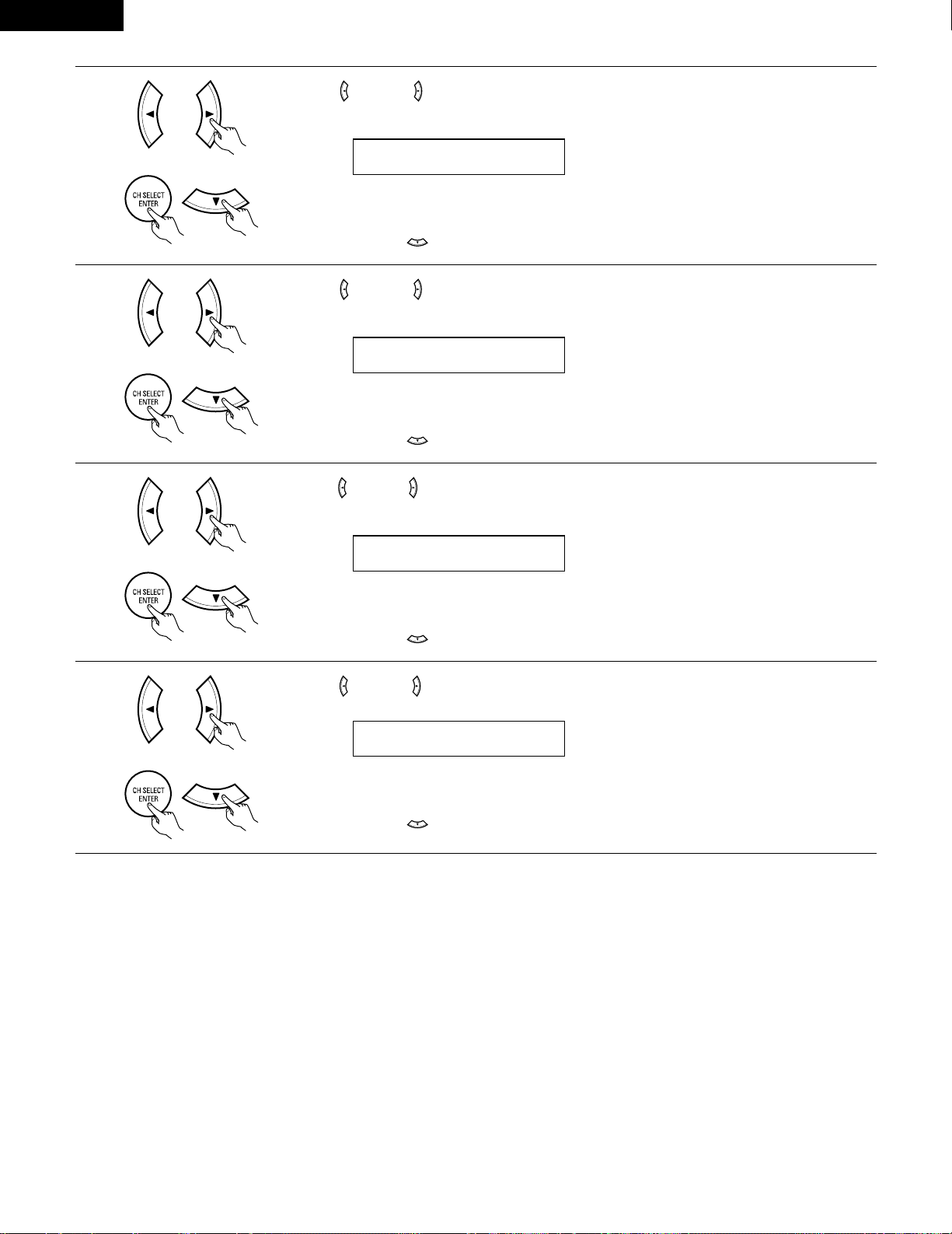
1
Use the (left) and (right) buttons to select your front speaker type.
1 FRONT LARGE
LARGE
SMALL
(left) button (right) button
Press the ENTER or (down) button to switch to the center speaker setting.
2
Use the (left) and (right) buttons to select your center speaker type.
2 CENTER SMALL
LARGE
SMALL
NONE
(left) button (right) button
Press the ENTER or (down) button to switch to the surround speaker setting.
3
Use the (left) and (right) buttons to select your surround speaker type.
3 SURR. SMALL
LARGE
SMALL
NONE
(left) button (right) button
Press the ENTER or (down) button to switch to the surround back speaker setting.
NOTE:
• When “Small” has been selected for the front speakers, “Large” cannot be selected for the center speaker.
(Initial)
(Initial)
(Initial)
NOTE:
• When “Small” has been selected for the front speakers, “Large” cannot be selected for the surround speakers.
Page 19
19
ENGLISH
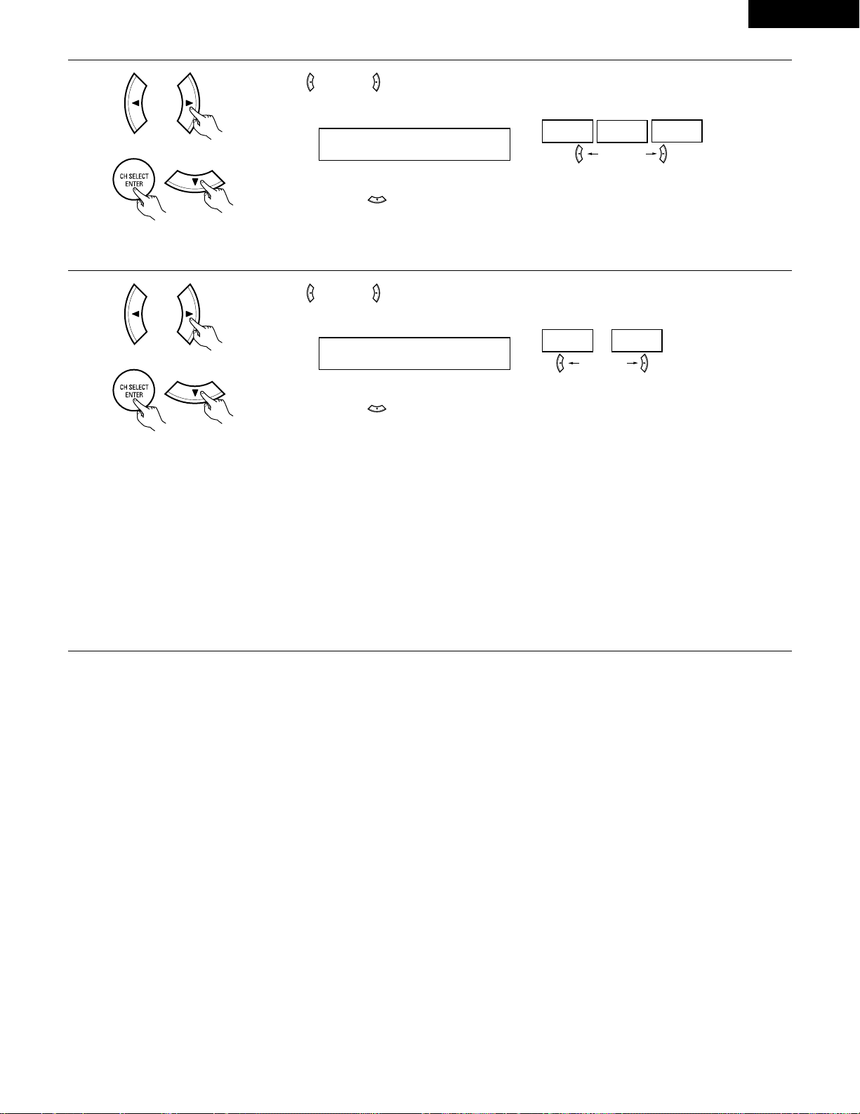
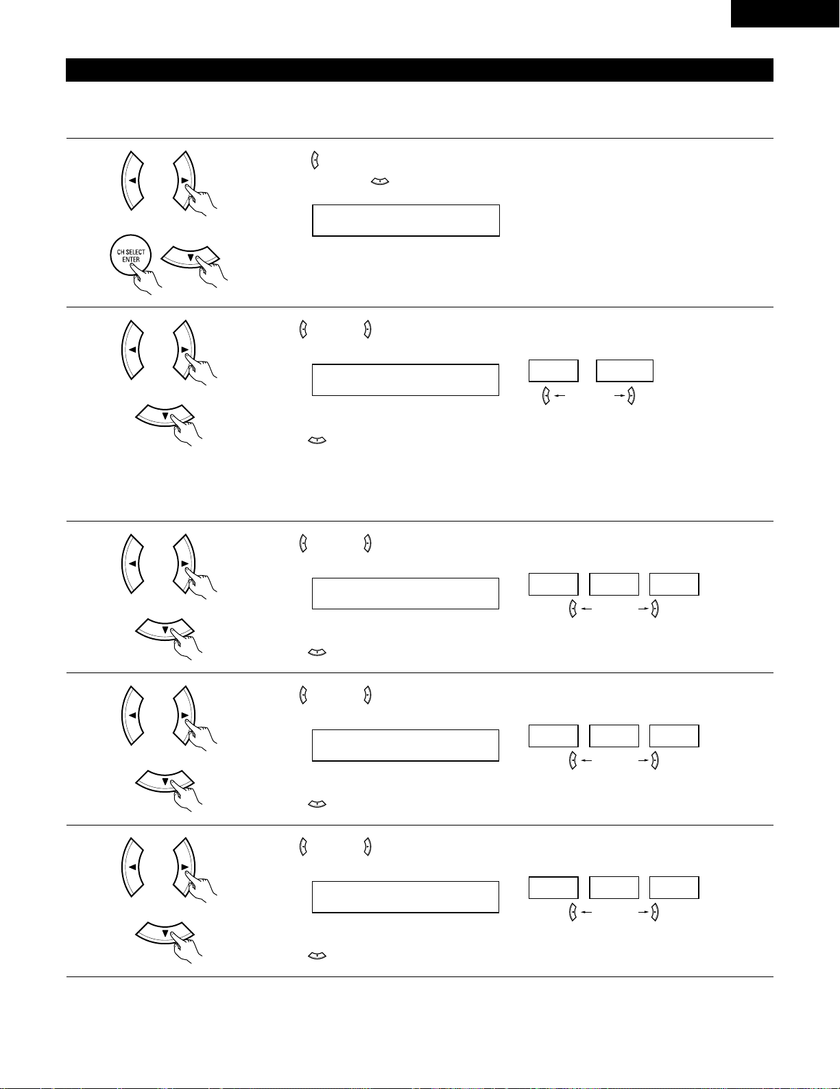
5
Use the (left) and (right) buttons to select your subwoofer setting.
5 S.WOOFER YES
YES
NO
(left) button (right) button
Press the ENTER or (down) button to enter the settings and switch to the subwoofer mode setting.
• Parameters
Large…… Select this when using speakers that can fully reproduce low sounds of below 80 Hz.
Small…… Select this when using speakers that cannot reproduce low sounds of below 80 Hz with sufficient volume. When this setting is
selected, low frequencies of below 80 Hz are assigned to the subwoofer.
None…… Select this when no speakers are installed.
Yes/No…. Select “Yes” when a subwoofer is installed, “No” when it’s not installed.
NOTE:
Select “Large” or “Small” not according to the physical size of the speaker , but according to the bass reproduction capacity at 80 Hz. If you cannot
determine the best setting, try comparing the sound when set to “Small” and when set to “Large”, at a level that will not damage the speakers.
Caution:
In case the subwoofer is not used, be sure to set “Subwoofer = No”, or the bass sound of front channel is divided to subwoofer channel and
not reproduced in some mode.
(Initial)
4
Use the (left) and (right) buttons to select your surround back speaker type.
4 S.BACK SMALL
LARGE
SMALL
NONE
(left) button (right) button
Press the ENTER or (down) button to switch to the subwoofer setting.
(Initial)
NOTE:
• When “Small” has been selected for the surround speakers, “Large” cannot be selected for the surround back speakers.
Page 20
20
ENGLISH
NOTES:
— Assignment of low frequency signal range —
• The signals produced from the subwoofer channel are LFE signals (during playback of Dolby Digital or DTS signals) and the low frequency
signal range of channels set to “SMALL” in the setup. The low frequency signal range of channels set to “LARGE” are produced from those
channels.
— Crossover Frequency —
• When “Subwoofer” is set to “Yes” at the “Speaker Configuration Setting”, set the frequency (Hz) below which the bass sound of the
various speakers is to be output from the subwoofer (the crossover frequency).
• For speakers set to “Small”, sound with a frequency below the crossover frequency is cut, and the cut bass sound is output from the
subwoofer instead.
NOTE: For ordinary speaker systems, we recommend setting the crossover frequency to 80 Hz. When using small speakers, however,
setting the crossover frequency to a high frequency may improve frequency response for frequencies near the crossover frequency.
— Subwoofer mode —
• The subwoofer mode setting is only valid when “LARGE” is set for the front speakers and “YES” is set for the subwoofer in the “Speaker
Configuration” settings (see pages 18, 19).
If “SMALL” is set for the front speakers or “NO” is set for the subwoofer, the subwoofer mode setting does not affect playback of low
frequency signal range.
• When the “+MAIN” playback mode is selected, the low frequency signal range of channels set to “LARGE” are produced simultaneously
from those channels and the subwoofer channel.
In this playback mode, the low frequency range expand more uniformly through the room, but depending on the size and shape of the room,
interference may result in a decrease of the actual volume of the low frequency range.
• When the “NORM” playback mode is selected, the low frequency signal range of channels set to “LARGE” are only produced from those
channels. In this playback mode there tends to be little interference of the low frequency range in the room.
• Try playing the music or movie source and select the playback mode providing the stronger low frequency range sound.
Setting the Subwoofer mode and Crossover Frequency
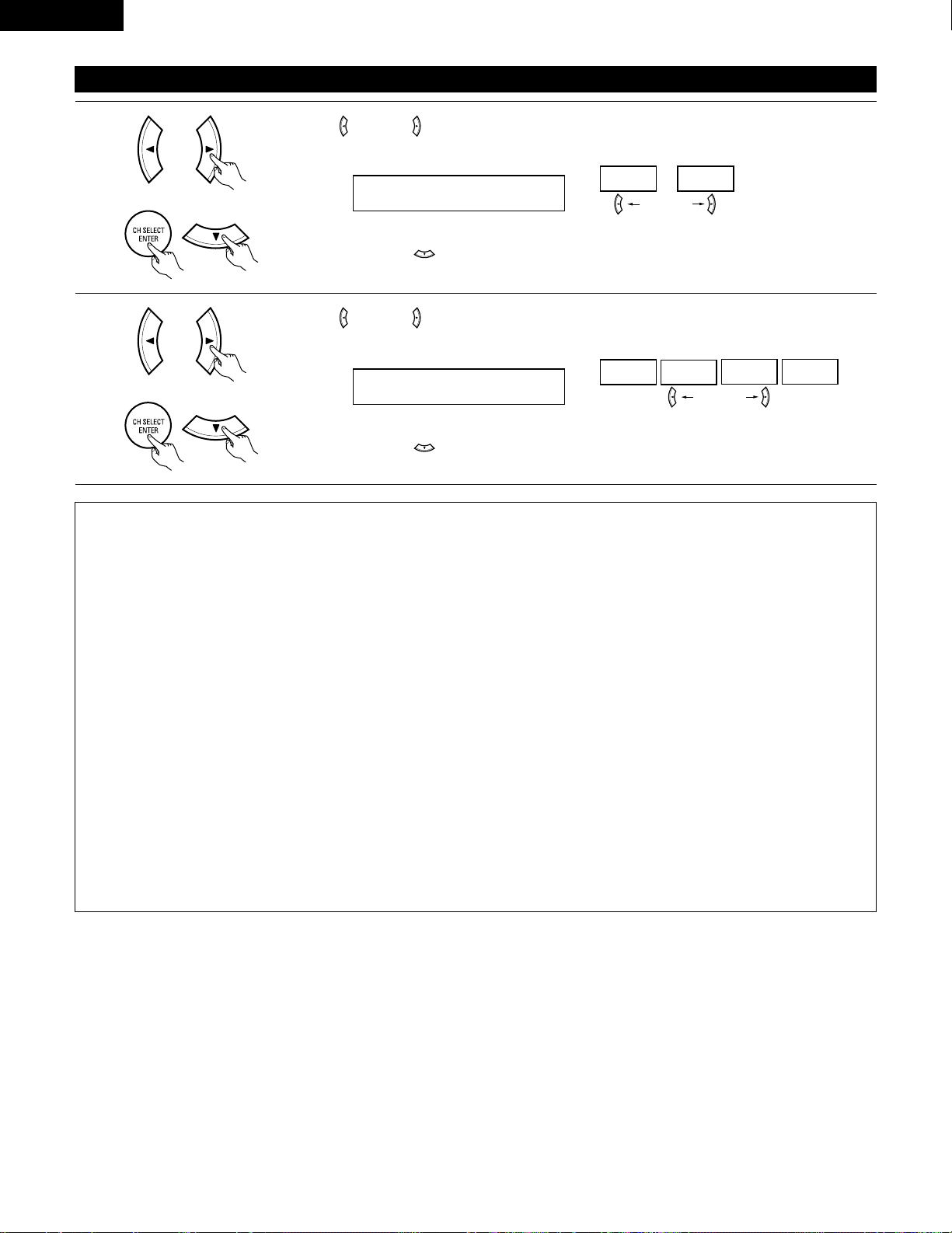
1
Use the (left) and (right) buttons to select the Subwoofer mode.
6 SW MODE NORM
NORM +MAIN
(left) button (right) button
Press the ENTER or (down) button to enter the setting and switch to the Crossover Frequency
setting.
(Initial)
2
Use the (left) and (right) buttons to select the Crossover Frequency.
7 CR.OVER 80Hz
80Hz
100Hz
120Hz 150Hz
(left) button (right) button
Press the ENTER or (down) button to enter the setting and switch to the SPEAKER DISTANCE
setting.
(Initial)
Page 21
21
ENGLISH
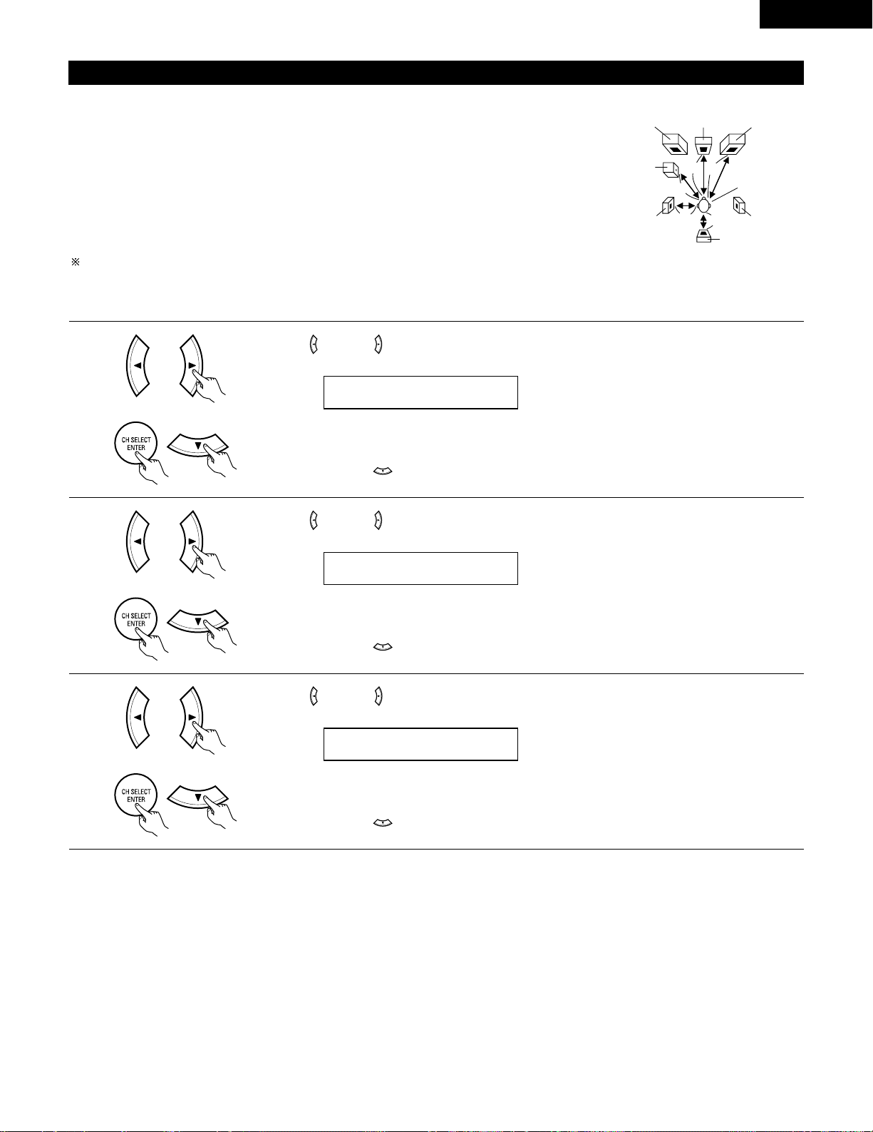
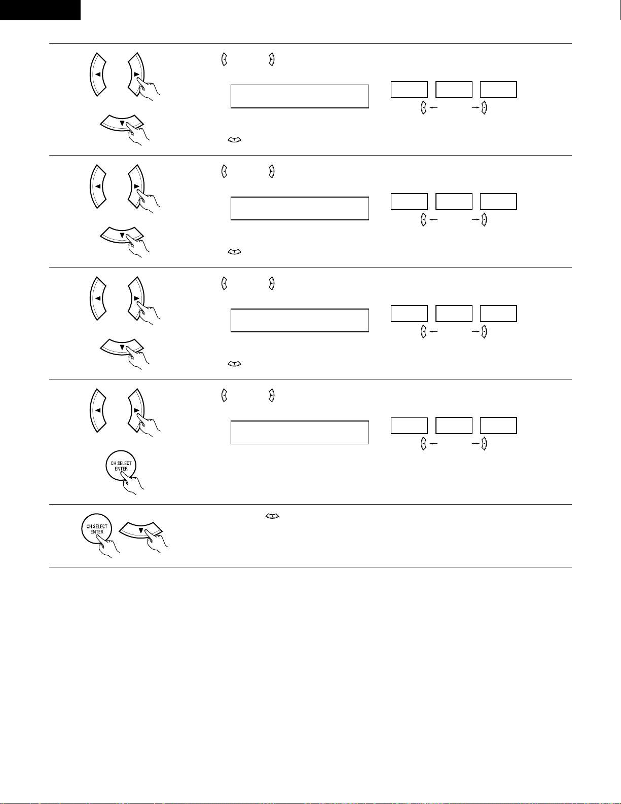
3
Use the (left) and (right) buttons to set the distance from the center speaker to the listening position.
10 CENTER 12ft
• The number changes in units of 1 foot each time one of the buttons is pressed. Select the value closest
to the measured distance.
Press the ENTER or (down) button to switch to the surround L speakers setting.
Setting the delay time
• Input the distance between the listening position and the different speakers to set the delay time for the surround mode.
Preparations:
Measure the distances between the listening position and the speakers (L1 to L5) on the diagram at
the right).
L1: Distance between center speaker and listening position
L2: Distance between front speakers and listening position
L3: Distance between surround speakers and listening position
L4: Distance between surround back speaker and listening position
L5: Distance between subwoofer and listening position
CAUTION:
Please note that the difference for every speaker should be 15 ft or less.
NOTE:
• No setting when “None” has been selected for the Speaker Configuration setting.
L1
L2
L5
L3
L4
Center FRFL
Subwoofer
SL
Listening position
SR
SB
1
Use the (left) and (right) buttons to set the distance from the front L speaker to the listening position.
8 FRONT L 12ft
• The number changes in units of 1 foot each time one of the buttons is pressed. Select the value closest
to the measured distance.
Press the ENTER or (down) button to switch to the front R speaker setting.
2
Use the (left) and (right) buttons to set the distance from the front R speaker to the listening position.
9 FRONT R 12ft
• The number changes in units of 1 foot each time one of the buttons is pressed. Select the value closest
to the measured distance.
Press the ENTER or (down) button to switch to the center speaker setting.
Page 22
22
ENGLISH
6
Use the (left) and (right) buttons to set the distance from the surround back speakers to the listening
position.
13 S.BACK 10ft
• The number changes in units of 1 foot each time one of the buttons is pressed. Select the value closest
to the measured distance.
Press the ENTER or (down) button to switch to the subwoofer setting.
5
Use the (left) and (right) buttons to set the distance from the surround R speakers to the listening
position.
12 SURR.R 10ft
• The number changes in units of 1 foot each time one of the buttons is pressed. Select the value closest
to the measured distance.
Press the ENTER or (down) button to switch to the surround back speaker setting.
7
Use the (left) and (right) buttons to set the distance from the subwoofer to the listening position.
14 SW 12ft
• The number changes in units of 1 foot each time one of the buttons is pressed. Select the value closest
to the measured distance.
Press the ENTER or (down) button to enter the setting and switch the Test Tone setting.
4
Use the (left) and (right) buttons to set the distance from the surround L speakers to the listening
position.
11 SURR.L 10ft
• The number changes in units of 1 foot each time one of the buttons is pressed. Select the value closest
to the measured distance.
Press the ENTER or (down) button to switch to the surround R speaker setting.
Page 23
23
ENGLISH
Setting the Test Tone
• Use this setting to adjust to that the playback level between the different channel is equal.
• From the listening position, listen to the test tones produced from the speakers to adjust the level.
• The level can also be adjusted directly from the remote control unit. (For details, see page 37.)
1
• Use the (left) button to switch the Test Tone mode.
• Press the ENTER or (down) button to switch to the DIGITAL input (COAX) setting.
15 T.TONE <YES
2
Use the (left) and (right) buttons to select the Test Tone mode.
T.TONE AUTO
AUTO
MANUAL
Press the (down) button to start Test Tone.
(left) button (right) button
3
Use the (left) and (right) buttons to set the front L channel level.
AUTO-FL
-12dB
0dB +12dB
Press the (down) button to switch to the center channel level (manual mode).
(left) button (right) button
4
Use the (left) and (right) buttons to set the center channel level.
AUTO-C
-12dB
0dB +12dB
Press the (down) button to switch to the front R channel level (manual mode).
(left) button (right) button
5
Use the (left) and (right) buttons to set the front R channel level.
AUTO-FR
-12dB
0dB +12dB
Press the (down) button to switch to the surround R channel level (manual mode).
(left) button (right) button
(Initial)
• Auto:
Adjust the level while listening to the test tones produced automatically from the different speakers.
• Manual:
Select the speaker from which you want to produce the test tone to adjust the level.
(Initial)
(Initial)
(Initial)
Page 24
24
ENGLISH
6
Use the (left) and (right) buttons to set the surround R channel level.
AUTO-SR
-12dB
0dB +12dB
Press the (down) button to switch to the surround back channel level (manual mode).
(left) button (right) button
7
Use the (left) and (right) buttons to set the surround back channel level.
AUTO-SB
-12dB
0dB +12dB
Press the (down) button to switch to the surround L channel level (manual mode).
(left) button (right) button
8
Use the (left) and (right) buttons to set the surround L channel level.
AUTO-SL
-12dB
0dB +12dB
Press the (down) button to switch to the subwoofer channel level (manual mode).
(left) button (right) button
9
Use the (left) and (right) buttons to set the subwoofer channel level.
AUTO-SW
-12dB
0dB +12dB
Press the ENTER button to finish the Test Tone.
(left) button (right) button
10
Press the ENTER or (down) button to switch the DIGITAL input (COAX) setting.
(Initial)
(Initial)
(Initial)
(Initial)
Page 25
25
ENGLISH
NOTE:
• TUNER, V. AUX cannot be selected.
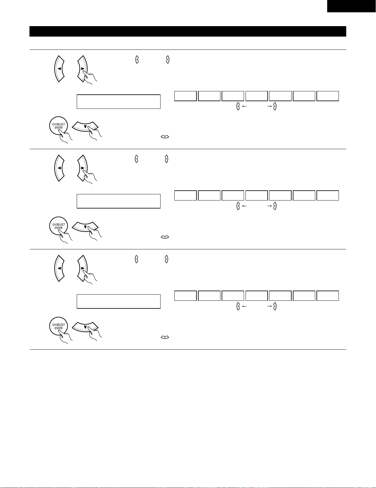
3
Use the (left) and (right) buttons to assign the input function connected to the OPTICAL input 2
(OPTICAL 2) terminal.
18 OPT2 TV
CD AUX DVD TV VCR CDR OFF
• Select “OFF” if nothing is connected.
Press the ENTER or (down) button to switch the auto surround mode setting.
(left) button (right) button
(Initial)
Setting the Digital In assignment
Input the type of components connected to the digital input terminals.
1
Use the (left) and (right) buttons to assign the input function connected to the COAXIAL input
(COAXIAL) terminal.
16 COAX CD
CD AUX DVD TV VCR CDR OFF
• Select “OFF” if nothing is connected.
Press the ENTER or (down) button to switch the optical input 1 (OPT1) setting.
(left) button (right) button
2
Use the (left) and (right) buttons to assign the input function connected to the OPTICAL input 1
(OPTICAL 1) terminal.
17 OPT1 DVD
CD AUX DVD TV VCR CDR OFF
• Select “OFF” if nothing is connected.
Press the ENTER or (down) button to switch the optical input 2 (OPT2) setting.
(left) button (right) button
(Initial)
(Initial)
Page 26
26
ENGLISH
After setting up the system
1
Press the SYSTEM SETUP button to finish system set up.
This completes the system setup operations. Once the system is set up, there is no need to make the settings again unless other components
or speakers are connected to or the speaker layout is changed.
Setting the Auto Surround Mode
For the three kinds of input signals as shown below, the surround mode played the last is stored in the memory. At next time it the same signal
inputs, the memorized surround mode is automatically selected and the signal is played.
Note that the surround mode setting is also stored separately for the different input function.
SIGNAL Default Auto Surround Mode
q Analog and PCM 2-channel signals STEREO
w 2-channel signals of Dolby Digital, DTS or other multichannel format Dolby PL
II Cinema
e Multichannel signals of Dolby Digital, DTS or other multichannel format Dolby or DTS Surround
1
Use the (left) and (right) buttons to select the Auto Surround mode.
19 AUTOSURR. ON
ON OFF
(left) button (right) button
Press the ENTER or (down) button to switch the Ext. In SW Level setting.
(Initial)
Setting the Ext. In SW Level
Set the method of playback of the analog input signal connected to the Ext. In terminal.
1
Use the (left) and (right) buttons to select the Ext. In Subwoofer channel Level playback.
20 EXT.IN SW +15
+00
+05
+10 +15
(left) button (right) button
Press the ENTER or (down) button if you want to start the settings over from the beginning.
(Initial)
Page 27
27
ENGLISH
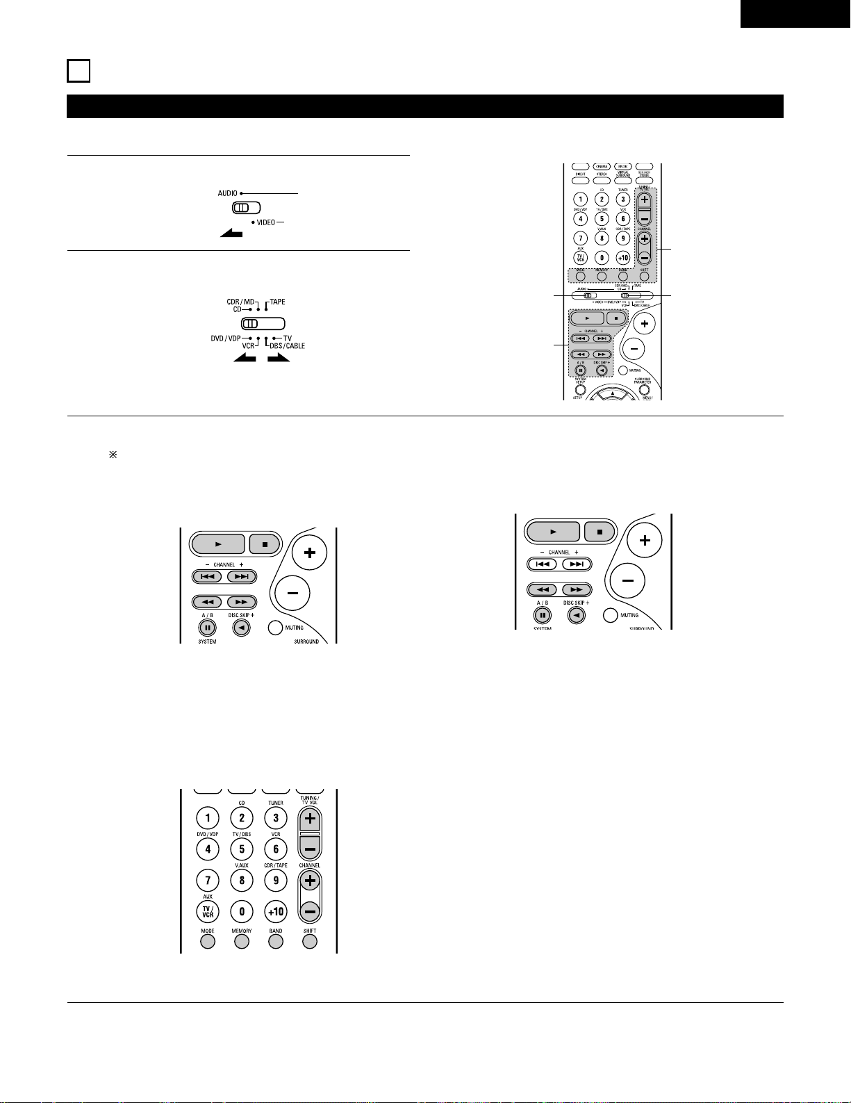
Operating DENON audio components
• Turn on the power of the different components before operating them.
1
2
3
Set mode switch 1 to “AUDIO”.
Set mode switch 2 to the position for the component to be
operated. (CD, CDR/MD or Tape deck)
Operate the audio component.
• For details, refer to the component’s operating instructions.
While this remote control is compatible with a wide range of infrared controlled components, some models of components may not
be operated with this remote control.
1. CD player (CD) and CD recorder and MD recorder
(CDR/MD) system buttons
3. Tuner system buttons
2. Tape deck (TAPE) system buttons
3
2
1
3
6, 7 : Manual search (forward and reverse)
2 : Stop
1 : Play
8, 9 : Auto search (cue)
3 : Pause
DISC : Switch discs
SKIP+ (for CD changers only)
SHIFT : Switch preset channel range
CHANNEL : Preset channel
+, – up/down
TUNING : Frequency
+, – up/down
BAND : Switch between the AM and FM bands
MODE : Switch between auto and mono
MEMORY : Preset memory
6 : Rewind
7 : Fast-forward
2 : Stop
1 : Forward play
0 : Reverse play
A/B : Switch between decks A and B
11
REMOTE CONTROL UNIT
NOTE:
• TUNER can be operated when the switch is at “AUDIO” position.
Page 28
28
ENGLISH
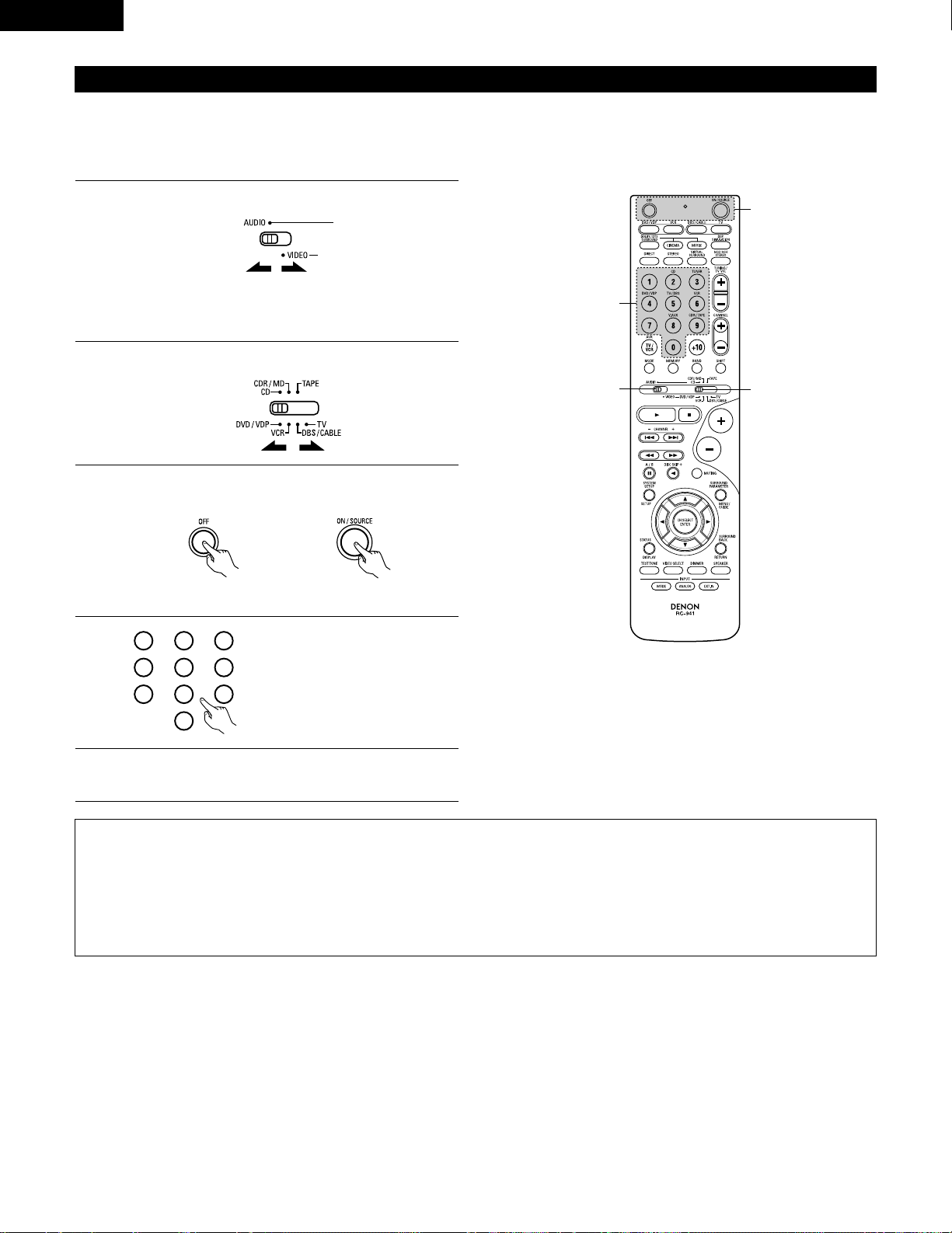
Preset memory
DENON and other makes of components can be operated by setting the preset memory.
This remote control unit can be used to operate components of other manufacturers without using the learning function by registering the
manufacturer of the component as shown on the List of Preset Codes (pages 122~126).
Operation is not possible for some models.
1
2
Set mode switch 1 to “AUDIO” or “VIDEO”.
Set mode switch 2 to the component to be registered.
3
2
1
4
Set the AUDIO side for the CD, Tape deck or CDR/MD
position, to the VIDEO side for the DVD/VDP, DBS/CABLE,
VCR or TV position.
3
Press the ON/SOURCE button and the OFF button at the
same time.
• Indicator flash.
4
5
Referring to the included List of
Preset Codes, use the number
buttons to input the preset code (a
3-digit number) for the manufacturer
of the component whose signals
you want to store in the memory.
To store the codes of another component in the memory,
repeat steps 1 to 4.
The preset codes are as follows upon shipment from the factory and after resetting:
TV, VCR .....................................................HITACHI
CD, TAPE..................................................DENON
CDR/MD ...................................................DENON (CDR)
DVD/VDP ..................................................DENON (DVD)
DBS/CABLE..............................................ABC (CABLE)
NOTES:
• The signals for the pressed buttons are emitted while setting the preset memory. To avoid accidental operation, cover the remote control
unit’s transmitting window while setting the preset memory.
• Depending on the model and year of manufacture, this function cannot be used for some models, even if they are of makes listed on the
included list of preset codes.
• Some manufacturers use more than one type of remote control code. Refer to the included list of preset codes to change the number and
check.
• The preset memory can be set for one component only among the following: CDR/MD, DVD/VDP and DBS/CABLE.
1
2
3
456
789
0
Page 29
29
ENGLISH
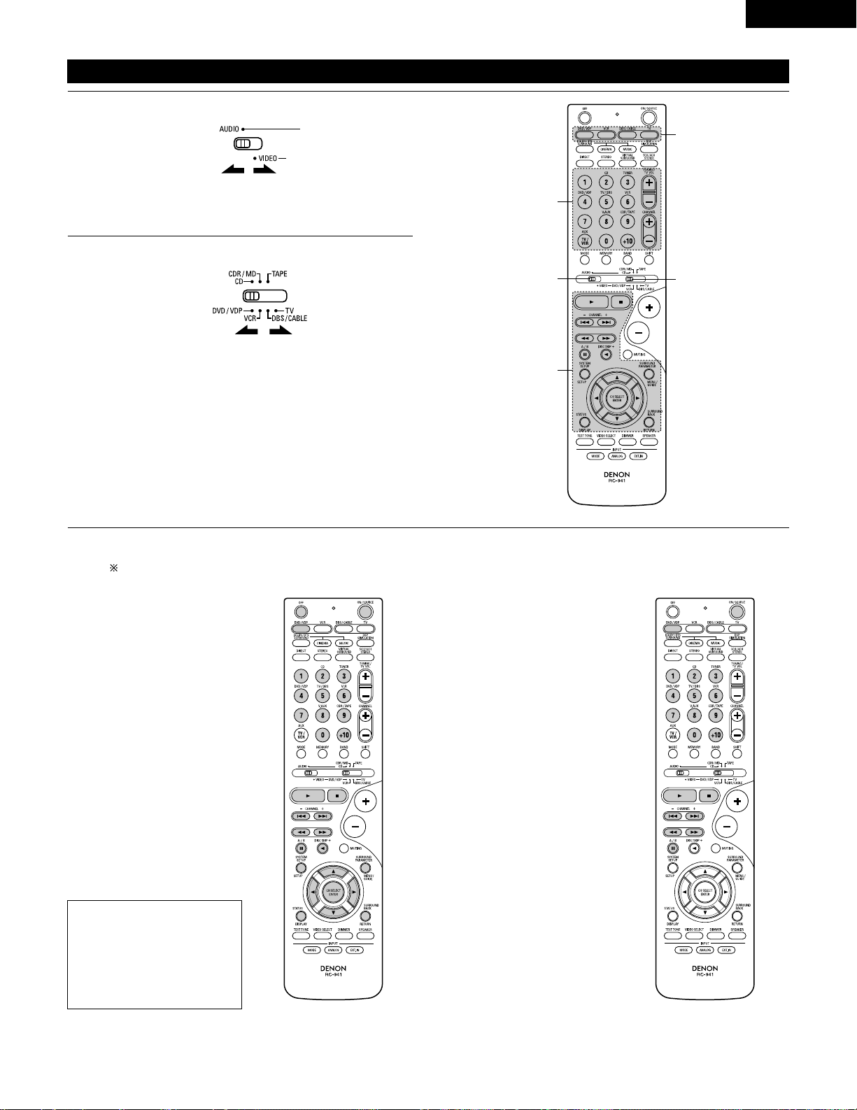
Operating component stored in the preset memory
1
2
Set mode switch 1 to “AUDIO” or “VIDEO”.
Set mode switch 2 to the component you want to operate.
3
2
1
3
3
Set the AUDIO side for the CD, tape deck or CDR/MD
position, to the VIDEO side for the DVD/VDP, DBS/CABLE,
VCR or TV position.
1. Digital video disc player (DVD,
DVD SETUP) system buttons
POWER : Power on/standby
(ON/SOURCE)
OFF : DENON DVD power off
6,7 : Manual search
(forward and reverse)
2 : Stop
1 :Play
8,9 : Auto search
(to beginning of track)
3 : Pause
0 ~ 9, +10 : 10 key
skip + : Disc skip
(for DVD changer only)
DISPLAY : Switch display
MENU : Menu
RETURN : Return
SETUP : Setup
•, ª,
0, 1
: Cursor up, down, left
and right
ENTER : Enter setting
2. Video disc player (VDP)
system buttons
POWER : Power on/standby
(ON/SOURCE)
6,7 : Manual search
(forward and reverse)
2 : Stop
1 :Play
8,9 : Auto search (cue)
3 : Pause
0~9, +10 : 10 key
3
Operate the component.
• For details, refer to the component’s operating instructions.
Some models cannot be operated with this remote control unit.
NOTE:
• Some manufacturers use
different names for the DVD
remote control buttons, so
also refer to the instructions
on remote control for that
component.
Page 30
30
ENGLISH
3. Video deck (VCR) system
buttons
4. Digital broadcast satellite
(DBS) tuner and cable
(CABLE) system buttons
POWER : Power on/standby
(ON/SOURCE)
6,7 : Manual search
(forward and reverse)
2 : Stop
1 :Play
3 : Pause
Channel +, – : Channels
POWER : Power on/standby
(ON/SOURCE)
MENU : Menu
RETURN : Return
•, ª,
0, 1
: Cursor up, down, left
and right
ENTER : Enter
CHANNEL : Switch channels
+, –
0~9, +10 : Channels
DISPLAY : Switch display
VOL +, – : Volume up/down
5. Monitor TV (TV) system
buttons
POWER : Power on/standby
(ON/SOURCE)
MENU : Menu
RETURN : Return
•, ª,
0, 1
: Cursor up, down, left
and right
ENTER : Enter
CHANNEL : Switch channels
+, –
0~9, +10 : Channels
DISPLAY : Switch display
TV/VCR : Switch between TV
and video player
TV VOL : Volume up/down
+, –
NOTES:
• For this CD, CDR, MD and TAPE components, buttons can be operated in the same way as for Denon audio components (page 27).
• The TV can be operated when the switch is at DVD/VDP, VCR, TV position.
Page 31

31
ENGLISH
Table 1
Punch Through
•“Punch Through” is a function allowing you to operate the PLAY, STOP, MANUAL SEARCH and AUTO SEARCH buttons on the CD, TAPE,
CDR/MD, DVD/VDP or VCR components when in the DBS/CABLE or TV mode. By default, nothing is set.
1
2
Set mode switch 1 to “VIDEO”.
Set mode switch 2 to the component to be registered
(DBS/CABLE or TV).
3
2
1
4
3
3
Press the DVD/VDP power button and the TV power button at
the same time.
• Indicator flash.
4
Input the number of the
component you want to set. (See
Table 1)
1
2
3
456
789
0
CD
TAPE
CDR/MD
DVD/VDP
VCR
No setting
No.
1
2
3
4
5
0
Page 32

32
ENGLISH
12
OPERATION
Before operating
Preparations:
Check that all connections are proper.
1
Turn on the power.
Press the ON/STANDBY button on the main unit or
ON/SOURCE button on the remote control unit to turn on the
power.
2
Select the front speakers.
Press the SPEAKER A or B button to turn the speaker on.
(Main unit) (Remote control unit)
• ON/STANDBY
When the button is pressed, the power turns on and the
display lights after approximately 1 second.
When pressed again, the power turns off, the standby
mode is set and the display turns off.
Several seconds are required from the time the power
operation switch is set to the “ON” position until sound is
output. This is due to the built-in muting circuit that prevents
noise when the power switch is turned on and off.
(Main unit) (Remote control unit)
• The front speaker A, B setting can be also be changed with
the SPEAKER button on the remote control unit.
1 2
1
2
Page 33

33
ENGLISH
Playing the input source
3
1 2 5
Input mode selection function
Different input modes can be selected for the different input sources.
The selected input modes for the separate input sources are stored
in the memory.
q AUTO (All auto mode)
In this mode, the types of signals being input to the digital and
analog input jacks for the selected input source are detected and
the program in the this unit’s surround decoder is selected
automatically upon playback. This mode can be selected for all
input sources other than TUNER.
The presence or absence of digital signals is detected, the signals
input to the digital input jacks are identified and decoding and
playback are performed automatically in DTS, Dolby Digital or
PCM (2 channel stereo) format. If no digital signal is being input,
the analog input jacks are selected.
Use this mode to play Dolby Digital signals.
w PCM (exclusive PCM signal playback mode)
Decoding and playback are only performed when PCM signals are
being input.
Note that noise may be generated when using this mode to play
signals other than PCM signals.
e DTS (exclusive DTS signal playback mode)
Decoding and playback are only performed when DTS signals are
being input.
r ANALOG (exclusive analog audio signal playback mode)
The signals input to the analog input jacks are decoded and
played.
t EXT. IN (external decoder input jack selection mode)
The signals being input to the external decoder input jacks are
played without passing through the surround circuitry.
NOTE:
• Note that noise will be output when CDs or LDs recorded in DTS
format are played in the “PCM” (exclusive PCM signal playback) or
“ANALOG” (exclusive analog audio signal playback) mode. Select
the AUTO or DTS (exclusive DTS signal playback) mode when
playing signals recorded in DTS from a laser disc player.
Notes on playing a source encoded with DTS
• Noise may be generated at the beginning of playback and
while searching during DTS playback in the AUTO mode. If
so, play in the DTS mode.
•
In some rare cases the noise may be generated when you
preform the operation to stop playback of a DTS-CD or DTS-LD.
5
1
3
2
1
Select the input source to be played.
Example: CD
(Main unit) (Remote control unit)
2
Select the input mode.
• Selecting the analog mode
Press the ANALOG button to switch to the analog input.
(Remote control unit)
• Selecting the external input (EXT. IN) mode
Press the EXT. IN (or the EXT. IN button on the remote
control unit) to switch the external input.
(Main unit) (Remote control unit)
• Selecting the AUTO, PCM and DTS modes
The mode switches as shown below each time the INPUT
MODE button is pressed.
AUTO PCM DTS
(Main unit)
(Main unit) (Remote control unit)
Page 34

34
ENGLISH
• To increase the bass or treble: Turn the control clockwise.
(The bass or treble sound can be increased to up to +12 dB
in steps of 2 dB.)
• To decrease the bass or treble: Turn the control
counterclockwise. (The bass or treble sound can be
decreased to up to –12 dB in steps of 2 dB.)
To select the surround mode while adjusting
the surround parameters, tone defeat or
tone control, press the surround mode
button then operate the selector.
3
Select the play mode.
Press the SURROUND MODE button, then turn the SELECT
knob.
Example: Stereo
(Main unit) (Remote control unit)
4
Start playback on the selected component.
• For operating instructions, refer to the component’s manual.
5
Adjust the volume.
(Main unit) (Remote control unit)
The volume level is
displayed on the
master volume level
display.
The volume can be adjusted within the range of –70 to 0 to 18 dB,
in steps of 1 dB. However, when the channel level is set as
described on page 37, if the volume for any channel is set at +1 dB
or greater, the volume cannot be adjusted up to 18 dB. (In this case
the maximum volume is adjusted to “18 dB — (Maximum value of
channel level)”.)
Input mode when playing DTS sources
• Noise will be output if DTS-compatible CDs or LDs are played in the
“ANALOG” or “PCM” mode.
When playing DTS-compatible sources, be sure to connect the
source component to the digital input jacks (OPTICAL/COAXIAL)
and set the input mode to “DTS”.
Input mode display
ANALOGDIGITAL
DIGITAL
DIGITAL
ANALOG
AUTO
PCM
DTS
INPUT
AUTO
PCM
DTS
INPUT
AUTO
PCM
DTS
INPUT
AUTO
PCM
DTS
INPUT
• In the AUTO mode
• In the DIGITAL PCM mode
• In the DIGITAL DTS mode
• In the ANALOG mode
One of these lights, depending on the
input signal.
Input signal display
SIGNAL
DIGITAL
DIGITAL
DIGITAL
SIGNAL
SIGNAL
• DOLBY DIGITAL
• DTS
• PCM
The indicator lights when digital signals are being input
properly. If the indicator does not light, check whether
the digital input component setup (page 25) and connections are
correct and whether the component’s power is turned on.
DIGITAL
DIGITAL
NOTE:
• The indicator will light when playing CD-ROMs
containing data other than audio signals, but no sound will be
heard.
DIGITAL
After starting playback
[1] Adjusting the sound quality (tone)
1
The tone switches as follows each time the TONE CONTROL
button is pressed.
BASS TREBLE
2
With the name of the volume to be
adjusted selected, turn the SELECT
knob to adjust the level.
32 1
(Main unit)
(Main unit)
3
If you do not want the bass and treble to be adjusted, turn on
the tone defeat mode.
The signals do not pass through the
bass and treble adjustment circuits,
so it provides higher quality sound.
(Main unit)
(Main unit)
Page 35

35
ENGLISH
Using the dimmer function
• Use this to change the
brightness of the display.
The display brightness
changes in four steps
(bright, medium, dim and
off) by pressing the main
unit’s DIMMER button
repeatedly.
Front panel display
• Descriptions of the unit’s
operations are also
displayed on the front
panel display. In addition,
the display can be
switched to check the
unit’s operating status
while playing a source by
pressing the STATUS
button.
Simulcast playback
Use this switch to monitor a
video source other than the
audio source.
Press the VIDEO SELECT
button repeatedly until the
desired source appears on
the display.
Cancelling simulcast playback.
• Select “SOURCE” using the video select button.
• Switch the program source to the component connected
to the video input jacks.
[3] Turning the sound off temporarily (muting)
1
Use this to turn off the audio output
temporarily.
Press the MUTING button.
Cancelling MUTING mode.
• Press the MUTING button again.
• Muting will also be cancelled when MASTER VOL is
adjusted up or down.
[4]
Combining the currently playing sound with the desired image
1
[5] Checking the currently playing program source, etc.
1
(Main unit)
(Remote control unit)
1
1
2
2 1
[2] Listening over headphones NOTE:
To prevent hearing loss, do not raise the volume level excessively
when using headphones.
1
Plug the headphones’ plug into the
jack.
Connect the headphones to the
PHONES jack.
The speaker output is automatically
turned off when headphones are
connected.
1
PHONES
(Main unit)
(Remote control unit)
1
1
2
(Main unit)
BRIGHT MEDIUM
OFF
DIM
(Remote control unit)
Page 36

36
ENGLISH
Set the external input (EXT.
IN) mode.
Press the EXT. IN to switch
the external input.
Once this is selected, the input signals connected to the FL
(front left), FR (front right), C (center), SL (surround left), and
SR (surround right) channels of the EXT. IN jacks are output
directly to the front (left and right), center, surround (left and
right) speaker systems without passing through the surround
circuitry.
In addition, the signal input to the SW (subwoofer) jack is
output to the PRE OUT SUBWOOFER jack.
Playback using the external input (EXT. IN) jacks
1
(Main unit)
(Remote control unit)
2
Cancelling the external input mode
T o cancel the external input (EXT. IN) setting, press the INPUT
MODE (AUTO, PCM, DTS) or ANALOG button to switch to
the desired input mode. (See page 33.)
(Remote control unit)
(Main unit)
• When the input mode is set to the external input (EXT. IN), the play
mode (DIRECT , STEREO, DOLBY/DTS SURROUND, 5/6CH STEREO
or DSP SIMULATION) cannot be selected.
NOTES:
• In play modes other than the external input mode, the signals
connected to EXT . IN jacks cannot be played. In addition, signals
cannot be output from channels not connected to the input
jacks.
• The external input mode can be set for any input source. To
watch video while listening to sound, select the input source to
which the video signal is connected, then set this mode.
• If the subwoofer output level seems to high, set the “SW ATT.”
surround parameter to “ON”.
2 1
21
Recording the program source (recording the source currently being monitored)
1
Follow step 1 to 3 under “Playing the input source”.
The signals of the source selected with the function selector button are output simultaneously to the CDR/TAPE and VCR REC OUT jacks. If
a total of two tape and/or video decks are connected and set to the recording mode, the same source can be recorded simultaneously on
every decks.
NOTE:
• The AUDIO IN’s signal selected with the input selector knob are output to the CDR/TAPE and VCR AUDIO OUT jacks.
2
Start recording on the tape or video deck.
For instructions, refer to the component’s operating
instructions.
Simultaneous recording
Page 37

37
ENGLISH
13
SURROUND
Before playing with the surround function
• Before playing with the surround function, be sure to use the test tones to adjust the playback level from each speakers. This adjustment can
be performed from the remote control unit, as (described) below.
• The adjustment with the test tones is only effective in the DOLBY/DTS SURROUND modes.
The adjusted playback levels for the different surround modes are automatically stored in the memory of each surround modes.
1
Set the DOLBY/DTS SURROUND (Dolby Pro Logic II or Dolby
Digital or DTS) modes.
2
Press the TEST TONE button.
3
After completing the adjustment, press the TEST TONE button
again.
(Main unit) (Remote control unit)
(Remote control unit)
Test tones are output from the
different speakers. Use the channel
volume adjust buttons to adjust so
that the volume of the test tones is
the same for all the speakers.
(Remote control unit)
1
2
2, 3
2
1
(Remote control unit)
NOTE: Please make sure the “AUDIO” position of the slide
switch on the remote control unit.
Page 38

38
ENGLISH
• After adjusting using the test tones, adjust the channel levels either according to the playback sources or to suit your tastes, as (described)
below.
1
Select the speaker whose level you want to adjust.
The channel switches as shown below each time the button
is pressed.
3
Adjust the level of the selected speaker.
FL CNTR FR SR SB
SW SL
(Remote control unit)
(Remote control unit)
3
1, 2
3
NOTE: Please make sure the “AUDIO” position of the slide
switch on the remote control unit.
Default setting of channel level is 0 dB.
The level of the selected speaker can be adjusted within
the range of +12 to –12 dB using cursor buttons.
SW channel level can be turned off by decreasing one step
from -12 dB.
OFF ´ -12 dB ´ 12 dB
2
(Remote control unit)
Page 39

39
ENGLISH
Dolby Surround Pro Logic IImode
2
Select the Dolby Surround Pro Logic II mode.
Light
(Main unit)
(Remote control unit)
3
Play a program source with the mark.
• For operating instructions, refer to the manuals of the
respective components.
5, 74, 61 2
4, 6
5, 7
1
8
5, 7
2
4
Select the surround parameter mode.
MODE Dolby PL
CINEMA EQ
TONE DEFEAT
DEFAULT
MODE CINEMA
CINEMA EQ
TONE DEFEAT
DEFAULT
MODE MUSIC
PANORAMA
DIMENSION
CENTER WIDTH
DEFAULT
TONE DEFEAT
SURROUND BACK
SURROUND BACK
SURROUND BACK
or or
MODE musicMODE cinemaMODE DOLBY PL
1
Select the function to which the component you want to play
is connected.
Example: DVD
(Main unit) (Remote control unit)
Display
(Main unit) (Remote control unit)
To perform this operation from the remote control unit,
check that the mode selector switch is set to “AUDIO”.
Display
5
Select the optimum mode for the source.
(Main unit) (Remote control unit)
6
Set the surround parameters according to the mode.
(Main unit) (Remote control unit)
• The mode switches as shown below each time the button
is pressed.
• The Dolby Pro Logic indicator lights.
The Dolby Surround Pro Logic II
Cinema or Music mode can be
chosen directly by pressing the
CINEMA or MUSIC button on
the remote control unit during
playback in the Dolby Surround
Pro Logic II mode.
MODE cinema
If you do want the bass and trable to be adjusted, turn off
the tone defeat mode.
Page 40

40
ENGLISH
NOTE:
• When making parameter settings, the display will return to the
regular condition several seconds after the last button was
pressed and the setting will be completed.
7
Set the various surround parameters.
• CINEMA EQ setting
ON OFF
or or
CINEMA EQ OFF
• PANORAMA setting
ON OFF
or or
PANORAMA OFF
• DIMENSION setting
0 3 6
or or
DIMENSION 3
• TONE DEFEAT setting
ON OFF
or or
TONE DEF. ON
• DEFAULT setting
YES Y/N NO
or or
DEFAULT Y/N
Select “Yes” to reset to the factory defaults.
8
Press the ENTER button to finish
surround parameter mode.
(Remote control unit)
DTS NEO:6 mode
5, 74, 61 2
1
Select the function to which the component you want to play
is connected.
Example: DVD
(Main unit) (Remote control unit)
4, 6
5, 7
1
8
5, 7
2
The DTS NEO:6 Cinema or
Music mode can be chosen
directly by pressing the CINEMA
or MUSIC button on the remote
control unit during playback in
the DTS NEO:6 mode.
• CENTER WIDTH setting
0
CENTER WIDTH 3
4 7
or or
• SURROUND BACK SPEAKER setting
ON OFF
or or
SB:ON
Page 41

41
ENGLISH
3
Play a program source.
4
Select the surround parameter mode.
MODE CINEMA
SURROUND BACK
DEFAULT
MODE MUSIC
SURROUND BACK
DEFAULT
CINEMA EQ CENTER IMAGE
TONE DEFEAT TONE DEFEAT
or or
MODE musicMODE cinema
(Main unit) (Remote control unit)
To perform this operation from the remote control unit,
check that the mode selector switch is set to “AUDIO”.
Display
5
Select the optimum mode for the source.
(Main unit) (Remote control unit)
6
Set the surround parameters according to the mode.
(Main unit) (Remote control unit)
• The mode switches as shown below each time the button
is pressed.
• The mode switches as shown below each time the button
is pressed.
DOLBY PLII cinema
DTS NEO:6
2
Select the DTS NEO:6 mode.
(Main unit)
(Remote control unit)
7
Set the various surround parameters.
• CINEMA EQ setting
ON OFF
or or
CINEMA EQ OFF
• CENTER IMAGE setting
0.0
C.IMAGE 0.2
0.2 0.5
or or
• DEFAULT setting
YES Y/N NO
or or
DEFAULT Y/N
Select “Yes” to reset to the factory defaults.
8
Press the ENTER button to finish surround parameter mode.
(Remote control unit)
MODE cinema
• TONE DEFEAT setting
ON OFF
or or
TONE DEF. ON
• SURROUND BACK SPEAKER setting
ON OFF
or or
SB:ON
If you do want the bass and trable to be adjusted, turn off
the tone defeat mode.
Page 42

42
ENGLISH
Surround parameters q
Pro Logic II Mode:
• The Cinema mode is for use with stereo television shows and all programs encoded Dolby Surround.
• The Music mode is recommended as the standard mode for autosound music systems (no video), and is optional for A/V systems.
• The Pro Logic mode offers the same robust surround processing as original Pro Logic in case the source contents is not of optimum quality.
Select one of the modes (“cinema”, “music” or “Pro Logic”).
Panorama Control:
This mode extends the front stereo image to include the surround speakers for an exciting “wraparound” effect with side wall imaging.
Select “OFF” or “ON”.
Dimension Control:
This control gradually adjust the soundfield either towards the front or towards the rear.
The control can be set in 7 steps from 0 to 6.
Center Width Control:
This control adjust the center image so it may be heard only from the center speaker; only from the left/right speakers as a phantom image;
or from all three front speakers to varying degrees.
The control can be set in 8 steps from 0 to 7.
DTS NEO:6 Mode:
• Cinema
This mode is optimum for playing movies. Decoding is performed with emphasis on separation performance to achieve the same
atmosphere with 2-channel sources as with 6.1-channel sources.
This mode is effective for playing sources recorded in conventional surround formats as well, because the in-phase component is assigned
mainly to the center channel (C) and the reversed phase component to the surround (SL, SR and SB channels).
• Music
This mode is suited mainly for playing music. The front channel (FL and FR) signals bypass the decoder and are played directly so there is
no loss of sound quality, and the effect of the surround signals output from the center (C) and surround (SL, SR and SB) channels add a
natural sense of expansion to the sound field.
CENTER IMAGE (0.0 to 0.5: default 0.2):
The center image parameter for adjusting the expansion of the center channel in the DTS NEO:6 MUSIC mode has been added.
Page 43

43
ENGLISH
Dolby Digital mode (only with digital input) and DTS Surround (only with digital input)
1
Select the input source.
q Select an input source set to digital (COAXIAL/OPTICAL)
(see page 25).
(Main unit) (Remote control unit)
w Set the input mode to “AUTO” or DTS.
2
Select the Dolby/DTS Surround mode.
(Remote control unit)
3
Play a program source with the , mark.
• The Dolby Digital indicator lights when
playing Dolby Digital sources.
DIGITAL
Light
23
1 1 3
4, 5, 6, 7, 8, 9, 10
3
5, 6, 7, 8, 9, 10
5, 6, 7, 8, 9, 10
5, 6, 7, 8, 9, 10
1
1
11
2
Playback with a digital input
• The DTS indicator lights when playing
DTS sources.
Light
4
Set the surround parameter according to the source.
First, press the SURROUND PARAMETER button.
(Remote control unit)
NOTE:
Please make sure the “AUDIO” position of the slide switch
on the remote control unit.
Example: DVD
(Main unit) (Remote control unit)
(Main unit)
Operate the SURROUND BACK button to switch Surround
Back CH ON/OFF.
(Remote control unit)(Main unit)
• Lights when the Surround Back CH is
on.
Light
Page 44

44
ENGLISH
Press the SURROUND PARAMETER or (down) button to switch to the D. COMP. setting.
Use the (left) and (right) buttons to set the CINEMA EQ.
5
CINEMA EQ OFF
ON
OFF
(left) button (right) button
(Initial)
(Remote control unit)
(Remote control unit)
6
Use the (left) and (right) buttons to set the D. COMP.
D.COMP. OFF
OFF LOW MID HIGH
Press the SURROUND PARAMETER or (down) button to switch to the LFE setting.
(left) button (right) button
(Remote control unit)
(Remote control unit)
7
Use the (left) and (right) buttons to set the LFE level.
LFE 0dB
-10dB
-5dB 0dB
• The level can be adjusted in units of 1 dB from –10 to 0 dB.
Set to the desired level according to the speaker systems being used and the source to be played.
Press the SURROUND PARAMETER or (down) button to switch to the TONE DEFEAT setting.
(Remote control unit)
(Remote control unit)
NOTE:
This parameter is not displayed during DTS playback.
(Initial)
(left) button (right) button
(Initial)
8
Use the (left) and (right) buttons to set the TONE DEFEAT.
TONE DEF. ON
ON
OFF
Press the SURROUND PARAMETER or (down) button to switch to the SURROUND BACK SPEAKER
setting.
(Remote control unit)
(Remote control unit)
(left) button (right) button
9
Use the (left) and (right) buttons to set the SURROUND BACK SPEAKER.
SB:ON
ON
OFF
Press the SURROUND PARAMETER or (down) button to switch to the default setting.
(Remote control unit)
(Remote control unit)
(left) button (right) button
(Initial)
(Initial)
Page 45

45
ENGLISH
2 Dialogue Normalization
The dialogue normalization function is activated automatically when playing Dolby Digital program sources.
Dialogue normalization is a basic function of Dolby Digital which automatically normalizes the dialog level (standard level) of the signals which are
recorded at different levels for different program sources, such as DVD, DTV and other future formats that will use Dolby Digital.
These contents can be verified with the STATUS button.
The number indicates the normalization level when the currently playing program is normalized to
the standard level.
OFFSET - 4dB
Display
Surround parameters w
CINEMA EQ. (Cinema Equalizer):
The Cinema EQ function gently decreases the level of the extreme high frequencies, compensating for overly-bright sounding motion picture
soundtracks. Select this function if the sound from the front speakers is too bright.
This function only works in the Dolby Pro Logic
II, Dolby Digital and DTS Surround modes. (The same contents are set for all operating modes.)
D.COMP. (Dynamic Range Compression):
Motion picture soundtracks have tremendous dynamic range (the contrast between very soft and very loud sounds). For listening late at night,
or whenever the maximum sound level is lower than usual, the Dynamic Range Compression allows you to hear all of the sounds in the
soundtrack (but with reduced dynamic range). (This only works when playing program sources recorded in Dolby Digital.) Select one of the four
parameters (“OFF”, “LOW”, “MID” (middle) or “HI” (high)). Set to OFF for normal listening.
LFE (Low Frequency Effect):
This sets the level of the LFE (Low Frequency Effect) sounds included in the source when playing program sources recorded in Dolby Digital
or DTS.
If the sound produced from the subwoofer sounds distorted due to the LFE signals when playing Dolby Digital or DTS sources when the peak
limiter is turned off with the subwoofer peak limit level setting (system setup menu), adjust the level as necessary.
Program source and adjustment range:
1. Dolby Digital: –10 dB to 0 dB
2. DTS Surround: –10 dB to 0 dB
When DTS encoded movie
software is played, it is recommended that the LFE LEVEL be set to 0 dB for correct DTS playback.
When DTS encoded music software is played, it is recommended that the LFE LEVEL be set to –10 dB for correct DTS playback.
SB CH OUT (Surround Back):
“OFF”..................Playback is conducted without using the surround back speaker.
“ON” ...................Playback is conducted using the surround back speaker.
NOTE: This operation can be performed directly using the “SURROUND BACK” button.
10
To reset the settings to the factory defaults, use the (left) and (right) buttons to display “Yes”.
DEFAULT Y/N
YES
Y/N NO
Press the SURROUND PARAMETER or (down) button to switch to the CINEMA EQ. setting.
(left) button (right) button
(Remote control unit)
(Remote control unit)
11
Press the ENTER button to finish surround parameter mode.
(Remote control unit)
Page 46

46
ENGLISH
14
DSP SURROUND SIMULATION
• This unit is equipped with a high performance DSP (Digital Signal Processor) which uses digital signal processing to synthetically recreate the
sound field. One of 7 preset surround modes can be selected according to the program source and the parameters can be adjusted according
to the conditions in the listening room to achieve a more realistic, powerful sound. These surround modes can also be used for program sources
not recorded in Dolby Surround Pro Logic or Dolby Digital.
Surround modes and their features
1
2
3
4
5
6
7 VIRTUAL
ROCK ARENA
JAZZ CLUB
VIDEO GAME
MONO MOVIE
(NOTE 1)
MATRIX
5CH/6CH
STEREO
Select this mode to enjoy a virtual sound field, produced from the front 2-channel speakers.
Use this mode to achieve the feeling of a live concert in an arena with reflected sounds coming from all directions.
This mode creates the sound field of a live house with a low ceiling and hard walls. This mode gives jazz a very
vivid realism.
Use this to enjoy video game sources.
Select this when watching monaural movies for a greater sense of expansion.
Select this to emphasize the sense of expansion for music sources recorded in stereo. Signals consisting of the
difference component of the input signals (the component that provides the sense of expansion) processed for
delay are output from the surround channel.
In this mode, the signals of the front left channel are output from the left surround channel, the signals of the front
right channel are output from the right surround channel, and the same (in-phase) component of the left and right
channels is output from the center channel. This mode provides all speaker surround sound, but without directional
steering effects, and works with any stereo program source.
Depending on the program source being played, the effect may not be very noticeable.
In this case, try other surround modes, without worrying about their names, to create a sound field suited to your tastes.
NOTE 1: When playing sources recorded in monaural, the sound will be one-sided if signals are only input to one channel (left or right), so input
signals to both channels. If you have a source component with only one audio output (monophonic camcorder, etc.) obtain a “Y” adaptor
cable to split the mono output to two outputs, and connect to the L and R inputs.
NOTE:
DIRECT, STEREO and 5CH/6CH STEREO mode can be used when playing PCM signals with a sampling frequency of 96 kHz (such as from
DVD-Video discs that contain 24 bit, 96 kHz audio). If such signals are input during playback in the other surround modes, the mode
automatically switches to STEREO.
Personal Memory Plus
This set is equipped with a personal memorize function that automatically memorizes the surround modes and input modes selected for the
input different sources. When the input source is switched, the modes set for that source last time it was used are automatically recalled.
The surround parameters, tone control settings and playback level balance for the different output channels are memorized for each
surround mode.
Page 47

47
ENGLISH
DSP surround simulation
1
Select the surround mode for the input channel.
(Remote control unit)
The surround mode switches in the following order each time
the DSP SIMULATION button is pressed:
2
33
4
1
2
To enter the surround parameter setting mode, press the SURROUND PARAMETER button.
• The surround parameter switches in the following order each time the SURROUND PARAMETER button is
pressed for the different surround modes.
MONO MOVIE ROCK ARENA
JAZZ CLUBVIDEO GAME
MATRIX
• To operate the surround mode and surround parameters from the
remote control unit.
(Remote control unit)
3
Use the (left) and (right) buttons to set the room size.
ROOM SIZE MED
LARGEMED-LMEDMED-SSMALL
(left) button (right) button
(Remote control unit)
(1) ROOM SIZE
Display the parameter you want to adjust, then use the (left) and (right) buttons to set it.
ROOM SIZE
EFFECT LEVEL
TONE DEFEAT
SURROUND BACK
DEFAULT
DELAY
TONE DEFEAT
SURROUND BACK
DEFAULT
TONE DEFEAT
DEFAULT
• ROCK ARENA
• JAZZ CLUB
• VIDEO GAME
• MONO MOVIE
• MATRIX • VIRTUAL
(Initial)
Use the (left) and (right) buttons to set the effect level.
EFFECT LEVEL 10
15101
(left) button (right) button
(Remote control unit)
(2) EFFECT LEVEL
(Initial)
(Remote control unit)
If you do want the bass and trable to be adjusted, turn off the tone defeat mode.
Page 48

48
ENGLISH
Use the (left) and (right) buttons to set the delay time.
DELAY 30ms
110ms30ms0ms
(left) button (right) button
(Remote control unit)
(3) DELAY TIME
(Remote control unit)
(7) DEFAULT
To reset the settings to the factory defaults, use the (left) and (right) buttons to display “Yes”.
DEFAULT Y/N
NOY/NYES
(left) button (right) button
(Initial)
Use the (left) and (right) buttons to set the D. COMP.
D.COMP. OFF
OFF LOW MID HIGH
(left) button (right) button
(Remote control unit)
NOTE:
This parameter is displayed during DOLBY DIGITAL playback.
(Initial)
(4) D. COMP.
4
Press the ENTER button to finish surround parameter mode.
(Remote control unit)
Use the (left) and (right) buttons to set the TONE DEFEAT.
TONE DEF. ON
ON
OFF
(left) button (right) button
(Remote control unit)
(5) TONE DEFEAT
Use the (left) and (right) buttons to set the SURROUND BACK SPEAKER.
SB:ON
ON
OFF
(left) button (right) button
(Remote control unit)
(6) SURROUND BACK SPEAKER
(Initial)
(Initial)
Page 49

49
ENGLISH
1
Turn the SELECT knob to select the surround mode.
(Main unit)
• When turned clockwise
2
Press the SURROUND PARAMETER button.
Press and hold in the surround parameter button to select the parameter you want to set.
• The parameters which can be set differ for the different surround modes. (Refer to “Surround Modes and Parameters” on page 50.
DIRECT STEREO DOLBY PRO LOGIC II
5CH/6CH STEREO
MONO MOVIE
JAZZ CLUB ROCK ARENAVIDEO GAMEMATRIXVIRTUAL SURROUND
DIRECT STEREO DOLBY PRO LOGIC II
5CH/6CH STEREO
MONO MOVIE
JAZZ CLUB ROCK ARENAVIDEO GAMEMATRIXVIRTUAL SURROUND
DTS NEO:6
DTS NEO:6
• Operating the surround mode and surround parameters from the main unit‘s panel.
1, 321
• When turned counterclockwise
To select the surround mode while adjusting the surround parameters, tone defeat or tone control, press the SURROUND MODE
button then operate the selector.
(Main unit)
(Main unit)
3
Display the parameter you want to adjust, then turn the SELECT knob to set it.
Surround parameters e
ROOM SIZE:
This sets the size of the sound field.
There are five settings: “small”, “med.s” (medium-small), “medium”, “med.l” (medium-large) and “large”. “small” recreates a small sound
field, “large” a large sound field.
EFFECT LEVEL:
This sets the strength of the surround effect.
The level can be set in 15 steps from 1 to 15. Lower the level if the sound seems distorted.
DELAY TIME:
In the matrix mode only, the delay time can be set within the range of 0 to 110 ms.
NOTE:
• When playing PCM digital signals or analog signals in the 5CH/6CH STEREO, ROCK ARENA, JAZZ CLUB, VIDEO GAME, MONO MOVIE or
MATRIX surround modes and the input signal switches to a digital signal encoded in Dolby Digital, the Dolby surround mode switches
automatically. When the input signal switches to a DTS signal, the mode automatically switches to DTS surround.
• When the “5CH/6CH STEREO” mode is selected, the display differs according to the Surround Back CH ON/OFF.
Surround Back CH ON: 6CH STEREO
Surround Back CH OFF: 5CH STEREO
Page 50

50
ENGLISH
C
C
E
C
*
E
C
E
E
E
E
E
E
E
C
2 Surround modes and parameters
Channel output
B
B
B
B
B
B
B
B
B
B
B
B
B
B
SUB-
WOOFER
E
E
B
B
B
B
B
B
B
B
B
B
B
E
SURROUND
L/R
E
E
B
B
B
B
B
B
B
B
B
B
B
E
CENTER
C
C
C
C
C
C
C
C
C
C
C
C
C
C
FRONT L/R
Mode
DIRECT
STEREO
EXTERNAL INPUT
DOLBY PRO LOGIC
II
DTS NEO:6
DOLBY DIGITAL
DTS SURROUND
5CH/6CH STEREO
ROCK ARENA
JAZZ CLUB
VIDEO GAME
MONO MOVIE
MATRIX
VIRTUAL
C : Signal
E : No signal
B : Turned on or off by speaker configuration setting
When
playing
Dolby
Digital
signals
When
playing
DTS
signals
C
C
E
E
C
E
C
E
E
E
E
E
E
C
Parameter (default values are shown in parentheses)
Dolby Digital
signals
D.COMP.
C (OFF)
C (OFF)
E
C (OFF)
–
C (OFF)
E
E
E
E
E
E
E
C (OFF)
E
E
E
E
E
E
E
E
E
E
E
E
C
(30msec)
E
DELAY
TIME
E
E
E
E
E
E
E
E
C (10)
C (10)
C (10)
C (10)
E
E
EFFECT
LEVEL
E
E
E
E
E
E
E
E
C
(Medium)
C
(Medium)
C
(Medium)
C
(Medium)
E
E
ROOM
SIZE
E
C (0dB)
C (0dB)
C (0dB)
C (0dB)
C (0dB)
C (0dB)
C (0dB)
C (0dB)
C (0dB)
C (0dB)
C (0dB)
C (0dB)
C (0dB)
TONE
CONTROL
Mode
DIRECT
STEREO
EXTERNAL INPUT
DOLBY PRO LOGIC
II
DTS NEO:6
DOLBY DIGITAL
DTS SURROUND
5CH/6CH STEREO
ROCK ARENA
JAZZ CLUB
VIDEO GAME
MONO MOVIE
MATRIX
VIRTUAL
C : Adjustable
E : Not adjustable
LFE
C (0dB)
C (0dB)
E
C (0dB)
–
C (0dB)
–
E
E
E
E
E
E
E
When
playing
PCM
signals
(96k)
C ( C )
C ( C )
E
C
C
E
E
C ( C )
C
C
C
C
C
C
When
playing
ANALOG
signals
C
C
C
C
C
E
E
C
C
C
C
C
C
C
C : Able
E : Unable
E
E
E
C
(CINEMA)
C
(CINEMA)
E
E
E
E
E
E
E
E
E
MODE
E
E
E
C (OFF)
–
E
E
E
E
E
E
E
E
E
PANORAMA
E
E
E
C (3)
–
E
E
E
E
E
E
E
E
E
DIMENSION
E
E
E
C (3)
–
E
E
E
E
E
E
E
E
E
CENTER
WIDTH
E
E
E
C (OFF)
C (OFF)
C (OFF)
C (OFF)
E
E
E
E
E
E
E
CINEMA
EQ
LFE
C (0dB)
C (0dB)
E
–
C (0dB)
–
C (0dB)
E
E
E
E
E
E
E
DTS
signals
PRO LOGIC II MUSIC MODE
ONLY
SURROUND PARAMETER
* Only for 2 ch contents.
E
E
B
B
B
B
B
B
B
B
B
B
B
E
SURROUND
BACK
E
E
E
E
C (0.2)
E
E
E
E
E
E
E
E
E
CENTER
IMAGE
NEO:6 MUSIC
MODE ONLY
E
E
C (OFF)
E
E
E
E
E
E
E
E
E
E
E
SW ATT.
Page 51

51
ENGLISH
15
LISTENING TO THE RADIO
Auto preset memory
1
When the main unit’s power operation switch turn on while
pressing the set’s PRESET DDbutton the unit automatically
begins searching for FM broadcast stations.
2
When the first FM broadcast station is found, that station is
stored in the preset memory at channel A1. Subsequent
stations are automatically stored in order at preset channels
A2 to A8, B1 to B8, C1 to C8, D1 to D8 and E1 to E8, for a
maximum of 40 stations.
3
Channel A1 is tuned in after the auto preset memory
operation is completed.
NOTES:
• If an FM station cannot be preset automatically due to poor
reception, use the “Manual tuning” operation to tune in the
station, then preset it using the manual “Preset memory”
operation.
• To interrupt this function, press the power operation button.
1
1
This unit is equipped with a function for automatically searching for FM broadcast stations and storing them in the preset memory.
2 DEFAULT VALUE
AUTO TUNER PRESETS
A1 ~ A8 87.5/89.1/98.1/107.9/90.1/90.1/90.1/90.1 MHz
B1 ~ B8 520/600/1000/1400/1500/1710 kHz/90.1/90.1 MHz
C1 ~ C8 90.1 MHz
D1 ~ D8 90.1 MHz
E1 ~ E8 90.1 MHz
Page 52

52
ENGLISH
Press the TUNING DD(+) or HH(–) button to tune in the desired
station.
The frequency changes continuously when the button is held
in.
Auto tuning
1
Set the input source to “TUNER”.
2
Watching the display, press the BAND button to select the
desired band (AM or FM).
3
Press the MODE button to set the auto tuning mode.
Lit
4
Press the TUNING UP DD(+) or HH(–) button.
• Automatic searching begins, then stops when a station is
tuned in.
NOTE:
• When in the auto tuning mode on the FM band, the “STEREO”
indicator lights on the display when a stereo broadcast is tuned in.
At open frequencies, the noise is muted and the “TUNED” and
“STEREO” indicators turn off.
2 41
Manual tuning
1
Set the input function to “TUNER”.
2
Watching the display, press the BAND button to select the
desired band (AM or FM).
3
Press the MODE button to set the manual tuning mode.
Check that the display’s “AUTO” indicator turns off.
4
NOTE:
• When the manual tuning mode is set, FM stereo broadcasts are received in monaural and the “STEREO” indicator turns off.
3
1
4
2
(Remote control unit)
(Main unit)
(Main unit) (Remote control unit)
(Remote control unit)(Main unit)
(Remote control unit)
Page 53

53
ENGLISH
Preset stations
1
Press the MEMORY button.
2
Press the SHIFT button and select the desired memory block
(A to E).
(Main unit) (Remote control unit)
3
Press the PRESET DD(+) or HH(–) button to select the desired
preset channel (1 to 8).
(Main unit) (Remote control unit)
4
Press the MEMORY button again to
store the station in the preset
memory.
To preset other channels, repeat steps 1 to 4.
A total of 40 broadcast stations can be preset – 8 stations
(channels 1 to 8) in each of blocks A to E.
32
1, 4
3
2
Recalling preset stations
Preparations:
Use the “Auto tuning” or “Manual tuning” operation to tune in the
station to be preset in the memory.
(Remote control unit)
(Remote control unit)
1
Watching the display, press the SHIFT button to select the
preset memory block.
(Main unit) (Remote control unit)
2
Watching the display, press the PRESET DD(+) or HH(–) button
to select the desired preset channel.
(Main unit) (Remote control unit)
21
2
1
NOTE: Please make sure the “AUDIO” position of the slide
switch on the remote control unit.
NOTE: Please make sure the “AUDIO” position of the slide
switch on the remote control unit.
Page 54

54
ENGLISH
16
LAST FUNCTION MEMORY
• This unit is equipped with a last function memory which stores the input and output setting conditions as they were immediately before the
power is switched off.
• The unit is also equipped with a back-up memory. This function provides approximately one week of memory storage when the main unit’s
power switch is off and with the power cord disconnected.
17
INITIALIZATION OF THE MICROPROCESSOR
When the indication of the display is not normal or when the operation of the unit does not shows the reasonable result, the initialization of the
microprocessor is required by the following procedure.
1
Switch off the unit and remove the AC cord from the wall
outlet.
2
Hold the following SPEAKER A button and B button, and plug
the AC cord into the outlet.
3
Check that the entire display is flashing with an interval of
about 1 second, and release your fingers from the 2 buttons
and the microprocessor will be initialized.
NOTES:
• If step 3 does not work, start over from step 1.
• If the microprocessor has been reset, all the button settings are
reset to the default values (the values set upon shipment from
the factory).
2
Page 55

55
ENGLISH
18
ADDITIONAL INFORMATION
Optimum surround sound for different sources
There are currently various types of multi-channel signals (signals or formats with more than two channels).
2 Types of multi-channel signals
Dolby Digital, Dolby Pro Logic, DTS, high definition 3-1 signals (Japan MUSE Hi-Vision audio), DVD-Audio, SACD (Super Audio CD), MPEG multichannel audio, etc.
“Source” here does not refer to the type of signal (format) but the recorded content. Sources can be divided into two major categories.
2 Types of sources
• Movie audio Signals created to be played in movie theaters. In general sound is recorded to be played in movie theaters equipped
with multiple surround speakers, regardless of the format (Dolby Digital, DTS, etc.).
FL C
SW
FR
FL C
SW
FR
SL SR
SB
SL SR
SB
Multiple surround speakers
Movie theater sound field
Listening room sound field
In this case it is important to achieve the same sense of
expansion as in a movie theater with the surround channels.
To do so, in some cases the number of surround speakers is
increased (to four or eight) or speakers with bipolar or dipolar
properties are used.
• Other types of audio These signals are designed to recreate a 360° sound field using three to five speakers.
In this case the speakers should surround the listener from all sides to create a uniform sound
field from 360°. Ideally the surround speakers should function as “point” sound sources in the
same way as the front speakers.
FL C
SW
FR
SL SR
These two types of sources thus have different properties, and different speaker settings, particularly for the surround speakers, are required
in order to achieve the ideal sound.
SL: Surround L channel
SR: Surround R channel
SB: Surround back channel
(For 6.1-channel system)
Page 56

56
ENGLISH
Surround back speakers
A 6.1-channel system is a conventional 5.1-channel system to which the “surround back” (SB) channel has been added. This makes it easy to
achieve sound positioned directly behind the listener, something that was previously difficult with sources designed for conventional multi
surround speakers. In addition, the acoustic image extending between the sides and the rear is narrowed, thus greatly improving the expression
of the surround signals for sounds moving from the sides to the back and from the front to the point directly behind the listening position.
FL C
SW
FR FL C
SW
FR
SR chSL ch
SL ch SR ch
SB ch
Change of positioning and acoustic image
with 5.1-channel systems
With this set, speaker(s) for 1 or 2 channels are required to achieve a 6.1-channel system (DTS-ES, etc.). Adding these speakers, however,
increases the surround effect not only with sources recorded in 6.1 channels but also with conventional 2- to 5.1-channel sources. All the Denon
original surround modes (see page 54) are compatible with 6.1-channel playback, so you can enjoy 6.1-channel sound with any signal source.
Movement of acoustic image from SR to SL
Change of positioning and acoustic image
with 6.1-channel systems
Movement of acoustic image from SR to SB to SL
2
Placement of the surround left and right channels when using surround back speakers
Using surround back speakers greatly improves the positioning of the sound at the rear. Because of this, the surround left and right channels
play an important role in achieving a smooth transition of the acoustic image from the front to the back. As shown on the diagram above, in a
movie theater the surround signals are also produced from diagonally in front of the listeners, creating an acoustic image as if the sound were
floating in space.
To achieve these effects, we recommend placing the speakers for the surround left and right channels slightly more towards the front than
with conventional surround systems. Doing so sometimes increases the surround effect when playing conventional 5.1-channel sources in the
6.1 surround or DTS-ES Matrix 6.1 mode. Check the surround effects of the various modes before selecting the surround mode.
Page 57

57
ENGLISH
• Set the front speakers, center speaker and subwoofer in the same
positions as in example (1).
• It is best to place the surround speakers directly at the side or slightly
to the front of the viewing position, and 2 to 3 feet (60 to 90 cm)
above the ears.
• Same as surround back speaker installation method (1).
Using dipolar speakers for the surround back speakers as well is
more effective.
• Connect the surround speakers to the surround speaker jacks.
• The signals from the surround channels reflect off the walls as
shown on the diagram at the left, creating an enveloping and realistic
surround sound presentation.
For multi-channel music sources however, the use of bipolar or dipolar
speakers mounted at the sides of the listening position may not be satisfactory in order to create a coherent 360 degree
surround sound field. Connect another pair of direct radiating speakers as described in example (3) and place them at
the rear corners of the room facing towards the prime listening position.
• Set the front speakers with their front surfaces as flush with the TV
or monitor screen as possible. Set the center speaker between the
front left and right speakers and no further from the listening position
than the front speakers.
• Consult the owner’s manual for your subwoofer for advice on placing
the subwoofer within the listening room.
• If the surround speakers are direct-radiating (monopolar) then place
them slightly behind and at an angle to the listening position and
parallel to the walls at a position 2 to 3 feet (60 to 90 cm) above ear
level at the prime listening position.
• When using two surround back speakers, place them at the back
facing the front at a narrower distance than the front left and right speakers. When using one surround back speaker,
place it at the rear center facing the front at a slightly higher position (0 to 20 cm) than the surround speakers.
• We recommend installing the surround back speaker(s) at a slightly downward facing angle. This effectively prevents
the surround back channel signals from reflecting off the monitor or screen at the front center, resulting in interference
and making the sense of movement from the front to the back less sharp.
Speaker setting examples
Here we describe a number of speaker settings for different purposes. Use these examples as guides to set up your system according to the type
of speakers used and the main usage purpose.
1. DTS-ES compatible system (using surround back speakers)
(1) Basic setting for primarily watching movies
(2) Setting for primarily watching movies using diffusion type speakers for the surround speakers
For the greatest sense of surround sound envelopment, diffuse radiation speakers such as bipolar types, or dipolar types, provide a wider
dispersion than is possible to obtain from a direct radiating speaker (monopolar). Place these speakers at either side of the prime listening
position, mounted above ear level.
Subwoofer
Surround speaker
Front speaker
2 to 3 feet
(60 to 90 cm)
Surround speaker
Front speaker
2 to 3 feet
(60 to 90 cm)
Surround back speakers
(1 spkr)
60°
Front speakers
60°
Monitor
Center speaker
As seen from above
As seen from above
As seen from the side
As seen from the side
Path of the surround sound from the
speakers to the listening position
Surround
speakers
Surround back speakers
(1 spkr)
60°
Surround
speakers
Surround back
speaker
Surround back
speaker
Point slightly
downwards
Point slightly
downwards
2. When not using surround back speakers
• Set the front speakers with their front surfaces as flush with the TV or
monitor screen as possible. Set the center speaker between the front left
and right speakers and no further from the listening position than the front
speakers.
• Consult the owner’s manual for your subwoofer for advice on placing the
subwoofer within the listening room.
• If the surround speakers are direct-radiating (monopolar) then place them
slightly behind and at an angle to the listening position and parallel to the
walls at a position 2 to 3 feet (60 to 90 cm) above ear level at the prime
listening position.
Subwoofer
Surround speaker
Front speaker
2 to 3 feet
(60 to 90 cm)
Surround speakers
120°
Front speakers
60°
Monitor
Center speaker
As seen from above
As seen from the side
Page 58

58
ENGLISH
Surround
The AVR-1604/684 is equipped with a digital signal processing circuit that lets you play program sources in the surround mode to achieve the same
sense of presence as in a movie theater.
Dolby Surround
(1) Dolby Digital
Dolby Digital is the multi-channel digital signal format developed by Dolby Laboratories.
Dolby Digital consists of up to “5.1” channels - front left, front right, center, surround left, surround right, and an additional channel exclusively
reserved for additional deep bass sound effects (the Low Frequency Effects – LFE – channel, also called the “.1” channel, containing bass
frequencies of up to 120 Hz).
Unlike the analog Dolby Pro Logic format, Dolby Digital’s main channels can all contain full range sound information, from the lowest bass, up
to the highest frequencies – 22 kHz. The signals within each channel are distinct from the others, allowing pinpoint sound imaging, and Dolby
Digital offers tremendous dynamic range from the most powerful sound effects to the quietest, softest sounds, free from noise and distortion.
2 Dolby Digital and Dolby Pro Logic
Comparison of home surround systems Dolby Digital Dolby Pro Logic
No. recorded channels (elements) 5.1 ch 2 ch
No. playback channels 5.1 ch 4 ch
Playback channels (max.) L, R, C, SL, SR, SW L, R, C, S (SW - recommended)
Audio processing
Digital discrete processing
Dolby Digital encoding/decoding
Analog matrix processing Dolby Surround
High frequency playback limit of surround
channel
20 kHz 7 kHz
2 Dolby Digital compatible media and playback methods
Marks indicating Dolby Digital compatibility: .
The following are general examples. Also refer to the player’s operating instructions.
LD (VDP)
Coaxial Dolby Digital RF output jack 1
Set the input mode to “AUTO”.
(Page 33)
DVD
Optical or coaxial digital output
(same as for PCM) 2
Set the input mode to “AUTO”.
(Page 33)
Others
(satellite broadcasts, CATV, etc.)
Optical or coaxial digital output
(same as for PCM)
Set the input mode to “AUTO”.
(Page 33)
Media Dolby Digital output jacks Playback method (reference page)
1 Please use a commercially available adapter when connecting the Dolby Digital RF output jack of the LD player to the digital input jack.
Please refer to the instruction manual of the adapter when making connection.
2 Some DVD digital outputs have the function of switching the Dolby Digital signal output method between “bit stream” and “(convert to)
PCM”. When playing in Dolby Digital surround on the AVR-1604/684, switch the DVD player’s output mode to “bit stream”. In some cases
players are equipped with both “bit stream + PCM” and “PCM only” digital outputs. In this case connect the “bit stream + PCM” jacks
to the AVR-1604/684.
(2) Dolby Pro Logic II
• Dolby Pro-Logic II is a new multi-channel playback format developed by Dolby Laboratories using feedback logic steering technology and
offering improvements over conventional Dolby Pro Logic circuits.
• Dolby Pro Logic II can be used to decode not only sources recorded in Dolby Surround ( ) but also regular stereo sources into five channels
(front left, front right, center, surround left and surround right) to achieve surround sound.
• Whereas with conventional Dolby Pro Logic the surround channel playback frequency band was limited, Dolby Pro Logic II offers a wider
band range (20 Hz to 20 kHz or greater). In addition, the surround channels were monaural (the surround left and right channels were the
same) with previous Dolby Pro Logic, but Dolby Pro Logic II they are played as stereo signals.
• Various parameters can be set according to the type of source and the contents, so it is possible to achieve optimum decoding (see page
48).
Sources recorded in Dolby Surround
These are sources in which three or more channels of surround have been recorded as two channels of signals using Dolby Surround
encoding technology.
Dolby Surround is used for the sound tracks of movies recorded on DVDs, LDs and video cassettes to be played on stereo VCRs, as well
as for the stereo broadcast signals of FM radio, TV, satellite broadcasts and cable TV.
Decoding these signals with Dolby Pro Logic makes it possible to achieve multi-channel surround playback. The signals can also be played
on ordinary stereo equipment, in which case they provide normal stereo sound.
Page 59

59
ENGLISH
DTS Digital Surround
Digital Theater Surround (also called simply DTS) is a multi-channel digital signal format developed by Digital Theater Systems.
DTS offers the same “5.1” playback channels as Dolby Digital (front left, front right and center, surround left and surround right) as well as the
stereo 2-channel mode. The signals for the different channels are fully independent, eliminating the risk of deterioration of sound quality due to
interference between signals, crosstalk, etc.
DTS features a relatively higher bit rate as compared to Dolby Digital (1234 kbps for CDs and LDs, 1536 kbps for DVDs) so it operates with a
relatively low compression rate. Because of this the amount of data is great, and when DTS playback is used in movie theaters, a separate CDROM synchronized with the film is played.
With LDs and DVDs, there is of course no need for an extra disc; the pictures and sound can be recorded simultaneously on the same disc, so
the discs can be handled in the same way as discs with other formats.
There are also music CDs recorded in DTS. These CDs include 5.1-channel surround signals (compared to two channels on current CDs). They do
not include picture data, but they offer surround playback on CD players that are equipped with digital outputs (PCM type digital output required).
DTS surround track playback offers the same intricate, grand sound as in a movie theater, right in your own listening room.
2 DTS compatible media and playback methods
Marks indicating DTS compatibility: and .
The following are general examples. Also refer to the player’s operating instructions.
CD
Optical or coaxial digital output
(same as for PCM) 2
Set the input mode to “AUTO” or “DTS” (page 33).
Never set the mode to “ANALOG” or “PCM”. 1
LD (VDP)
Optical or coaxial digital output
(same as for PCM) 2
Set the input mode to “AUTO” or “DTS” (page 33).
Never set the mode to “ANALOG” or “PCM”. 1
DVD
Optical or coaxial digital output
(same as for PCM) 3
Set the input mode to “AUTO” or “DTS” (page 33).
Media Dolby Digital output jacks Playback method (reference page)
1 DTS signals are recorded in the same way on CDs and LDs as PCM signals. Because of this, the un-decoded DTS signals are output as
random “hissy” noise from the CD or LD player’s analog outputs. If this noise is played with the amplifier set at a very high volume, it may
possibly cause damage to the speakers. To avoid this, be sure to switch the input mode to “AUTO” or “DTS” before playing CDs or LDs
recorded in DTS. Also, never switch the input mode to “ANALOG” or “PCM” during playback. The same holds true when playing CDs or
LDs on a DVD player or LD/DVD compatible player. For DVDs, the DTS signals are recorded in a special way so this problem does not occur.
2 The signals provided at the digital outputs of a CD or LD player may undergo some sort of internal signal processing (output level
adjustment, sampling frequency conversion, etc.). In this case the DTS-encoded signals may be processed erroneously, in which case they
cannot be decoded by the AVR-1604/684, or may only produce noise. Before playing DTS signals for the first time, turn down the master
volume to a low level, start playing the DTS disc, then check whether the DTS indicator on the AVR-1604/684 (see page 51) lights before
turning up the master volume.
3 A DVD player with DTS-compatible digital output is required to play DTS DVDs. A DTS Digital Output logo is featured on the front panel of
compatible DVD players. Recent DENON DVD player models feature DTS-compatible digital output – consult the player’s owner’s manual
for information on configuring the digital output for DTS playback of DTS-encoded DVDs.
Manufactured under license from Digital Theater Systems, Inc. US Pat. No. 5,451,942, 5,956,674, 5,974,380, 5,978,762 and other world-wide
patents issued and pending.
“DTS”,”DTS-ES Extended Surround” and “Neo:6” are trademarks of Digital Theater Systems, Inc. ©1996, 2000 Digital Theater Systems, Inc.
All Rights Reserved.
There are two types of DVD Dolby surround recording signals.
q 2-channel PCM stereo signals
w 2-channel Dolby Digital signals
When either of these signals is input to the AVR-1604/684, the surround mode is automatically set to Dolby Pro Logic II when the
“DOLBY/DTS SURROUND” mode is selected.
2 Sources recorded in Dolby Surround are indicated with the logo mark shown below.
Dolby Surround support mark:
Manufactured under license from Dolby Laboratories.
“Dolby”, “Pro Logic” and the double-D symbol are trademarks of Dolby Laboratories.
Page 60

60
ENGLISH
DTS-ES Extended Surround
TM
DTS-ES Extended Surround is a new multi-channel digital signal format developed by Digital Theater Systems Inc. While offering high compatibility
with the conventional DTS Digital Surround format, DTS-ES Extended Surround greatly improves the 360-degree surround impression and space
expression thanks to further expanded surround signals. This format has been used professionally in movie theaters since 1999.
In addition to the 5.1 surround channels (FL, FR, C, SL, SR and LFE), DTS-ES Extended Surround also offers the SB (Surround Back, sometimes
also referred to as “surround center”) channel for surround playback with a total of 6.1 channels. DTS-ES Extended Surround includes two signal
formats with different surround signal recording methods, as described below.
2 DTS-ES
TM
Discrete 6.1
DTS-ES Discrete 6.1 is the newest recording format. With it, all 6.1 channels (including the SB channel) are recorded independently using a
digital discrete system. The main feature of this format is that because the SL, SR and SB channels are fully independent, the sound can be
designed with total freedom and it is possible to achieve a sense that the acoustic images are moving about freely among the background
sounds surrounding the listener from 360 degrees.
Though maximum performance is achieved when sound tracks recorded with this system are played using a DTS-ES decoder, when played
with a conventional DTS decoder the SB channel signals are automatically down-mixed to the SL and SR channels, so none of the signal
components are lost.
2 DTS-ES
TM
Matrix 6.1
With this format, the additional SB channel signals undergo matrix encoding and are input to the SL and SR channels beforehand. Upon
playback they are decoded to the SL, SR and SB channels. The performance of the encoder used at the time of recording can be fully matched
using a high precision digital matrix decoder developed by DTS, thereby achieving surround sound more faithful to the producer’s sound design
aims than with conventional 5.1- or 6.1-channel systems.
In addition, the bit stream format is 100% compatible with conventional DTS signals, so the effect of the Matrix 6.1 format can be achieved
even with 5.1-channel signal sources. Of course it is also possible to play DTS-ES Matrix 6.1 encoded sources with a DTS 5.1-channel decoder.
When DTS-ES Discrete 6.1 or Matrix 6.1 encoded sources are decoded with a DTS-ES decoder, the format is automatically detected upon
decoding and the optimum playing mode is selected. However, some Matrix 6.1 sources may be detected as having a 5.1-channel format, so the
DTS-ES Matrix 6.1 mode must be set manually to play these sources.
(For instructions on selecting the surround mode, see page 51.)
The DTS-ES decoder includes another function, the DTS Neo:6 surround mode for 6.1-channel playback of digital PCM and analog signal sources.
2 DTS Neo:6
TM
surround
This mode applies conventional 2-channel signals to the high precision digital matrix decoder used for DTS-ES Matrix 6.1 to achieve 6.1channel surround playback. High precision input signal detection and matrix processing enable full band reproduction (frequency response of
20 Hz to 20 kHz or greater) for all 6.1 channels, and separation between the different channels is improved to the same level as that of a digital
discrete system.
DTS Neo:6 surround includes two modes for selecting the optimum decoding for the signal source.
• DTS Neo:6 Cinema
This mode is optimum for playing movies. Decoding is performed with emphasis on separation performance to achieve the same
atmosphere with 2-channel sources as with 6.1-channel sources.
This mode is effective for playing sources recorded in conventional surround formats as well, because the in-phase component is assigned
mainly to the center channel (C) and the reversed phase component to the surround (SL, SR and SB channels).
• DTS Neo:6 Music
This mode is suited mainly for playing music. The front channel (FL and FR) signals bypass the decoder and are played directly so there is
no loss of sound quality, and the effect of the surround signals output from the center (C) and surround (SL, SR and SB) channels add a
natural sense of expansion to the sound field.
Page 61
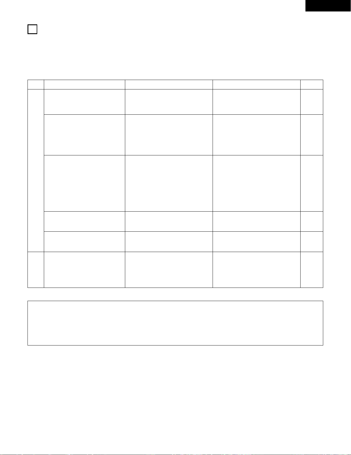
61
ENGLISH
19
TROUBLESHOOTING
If a problem should arise,first check the following.
1. Are the connections correct ?
2. Have you operated the receiver according to the Operating Instructions ?
3. Are the speakers and other components operating property ?
If this unit is not operating properly, check the items listed in the table below. Should the problem persist, there may be a malfunction.
Disconnect the power immediately and contact your store of purchase.
Symptom
Cause
Measures
Page
DISPLAY not lit and sound not produced
when power switch set to on.
• Power cord not plugged in securely. • Check the insertion of the power cord plug.
• Turn the power off with the remote control
unit after turning the POWER operation
switch on.
9
32
DISPLAY lit but sound not produced.
• Speaker cords not securely connected.
• Improper position of the audio function
button.
• Volume control set to minimum.
• MUTING is on.
• Digital signals not input Digital input
selected.
• Connect securely.
• Set to a suitable position.
• Turn volume up to suitable level.
• Switch off MUTING.
• Input digital signals or select input jacks to
which digital signals are being input.
14, 15
33
34
35
34
DISPLAY not displayed and the
“ON/STANDBY” LED flashes at a high
rate
• Speaker terminals are short-circuited.
• Block the ventilation holes of the set.
• The unit is operating at continuous high
power conditions and/or inadequate
ventilation.
• Switch power off, connect speakers
properly, then switch power back on.
• Turn off the set’s power, then ventilate it
well to cool it down.
Once the set is cooled down, turn the
power back on.
• Turn off the set’s power, then ventilate it
well to cool it down.
Once the set is cooled down, turn the
power back on.
14, 15
5, 15
5, 15
Sound produced only from one channel.
• Incomplete connection of speaker cords.
• Incomplete connection of input/output
cords.
• Connect securely.
• Connect securely.
14, 15
9 ~ 15
Positions of instruments reversed during
stereo playback.
• Reverse connections of left and right
speakers or left and right input/output
cords.
• Check left and right connections.
14, 15
This unit does not operate properly when
remote control unit is used.
• Batteries dead.
• Remote control unit too far from this unit.
• Obstacle between this unit and remote
control unit.
• Different button is being pressed.
• < and > ends of battery inserted in reverse.
• Replace with new batteries.
• Move closer.
• Remove obstacle.
• Press the proper button.
• Insert batteries properly.
16
16
16
—
16
Common problems arising when listening to the
CD, records, tapes, and FM broadcasts, etc.
Remote control
unit.
Note:
When a subwoofer has been connected and the virtual surround function is being used, the signal played from the subwoofer channel is LFE
only (only when playing Dolby Digital or DTS signals) for initial factory settings (i.e., the setting of the front speaker is “LARGE” and the setting
of the subwoofer mode is “NORM”).
When subwoofer effects are felt to be weak, while in the system setup mode try setting the subwoofer mode to “+MAIN”, or the front
speaker to “SMALL” in the system setup “Speaker Configuration” settings.
Making these settings will result in the low-frequency sounds of the front channel being played from the subwoofer.
Page 62

62
ENGLISH
20
SPECIFICATIONS
2 Audio section
• Power amplifier
Rated output: Front: 75 W + 75 W (8 Ω/ohms, 20 Hz ~ 20 kHz with 0.08% T.H.D.)
110 W + 110 W (6 Ω/ohms, 1 kHz with 0.7% T.H.D.)
Center: 75 W (8 Ω/ohms, 20 Hz ~ 20 kHz with 0.08% T.H.D.)
110 W (6 Ω/ohms, 1 kHz with 0.7% T.H.D.)
Surround: 75 W + 75 W (8 Ω/ohms, 20 Hz ~ 20 kHz with 0.08% T.H.D.)
110 W + 110 W (6 Ω/ohms, 1 kHz with 0.7% T.H.D.)
Surround back: 75W (8 Ω/ohms, 20 Hz ~ 20 kHz with 0.08% T.H.D.)
110 W (6 Ω/ohms, 1 kHz with 0.7% T.H.D.)
Output terminals: Front: A or B 16 to 16 Ω/ohms
A + B 12 to 16 Ω/ohms
Center/Surround/Surr. Back: 16 to 16 Ω/ohms
• Analog
Input sensitivity / input impedance: 200 mV / 47 kΩ/kohms
Frequency response: 10 Hz ~ 100 kHz: +1, –3 dB (TONE DEFEAT ON)
S/N ratio: 98 dB (IHF-A weighted) (TONE DEFEAT ON)
2 Video section
• Standard video jacks
Input / output level and impedance: 1 Vp-p, 75 Ω/ohms
Frequency response: 5 Hz ~ 10 MHz — +1, –3 dB
• S-video jacks
Input / output level and impedance: Y (brightness) signal — 1 Vp-p, 75 Ω/ohms
C (color) signal — 0.286 Vp-p, 75 Ω/ohms
Frequency response: 5 Hz ~ 10 MHz — +1, –3 dB
• Color component video jacks
Input / output level and impedance: Y (brightness) signal — 1 Vp-p, 75 Ω/ohms
PB/CB (blue) signal — 0.7 Vp-p, 75 Ω/ohms
P
R/CR
(red) signal — 0.7 Vp-p, 75 Ω/ohms
Frequency response: 5 Hz ~ 30 MHz — +0, –3 dB
2 Tuner section
[FM] (note: µV at 75 Ω/ohms, 0 dBf = 1 x 10
–
15
W) [AM]
Receiving range: 87.50 MHz ~ 107.90 MHz 520 kHz ~ 1710 kHz
Usable sensitivity: 1.0 µV (11.2 dBf) 18 µV
50 dB quieting sensitivity: MONO 1.6 µV (15.3 dBf)
STEREO 23 µV (38.5 dBf)
S/N ratio: MONO 80 dB (IHF-A weighted)
STEREO 75 dB (IHF-A weighted)
Total harmonic distortion: MONO 0.15% (1kHz)
STEREO 0.3% (1kHz)
2 General
Power supply: AC 120 V, 60 Hz
Power consumption: 4.0 A
Maximum external dimensions: 434 (W) x 147 (H) x 417 (D) mm (17-3/32” x 5-25/32” x 16-23/64”)
Mass: 10.8 kg (23 lbs 13 oz)
2 Remote control unit (RC-941)
Batteries: R6P/AA Type (two batteries)
External dimensions: 55 (W) x 225 (H) x 34.5 (D) mm (2-11/64” x 8-55/64” x 1-9/64”)
Mass: 165 g (Approx. 5.8 oz) (including batteries)
* For purposes of improvement, specifications and design are subject to change without notice.
Page 63

63
FRANCAIS
2 INTRODUCTION
2 ACCESSOIRES
Nous vous remercions d‘avoir choisi l’ampli-tuner A/V Surround de DENON.
Ce remarquable composant a été fabriqué pour fournir une superbe écoute de sons d’ambiance avec des sources de cinéma domestique telles
que DVD, ainsi que pour assurer une formidable reproduction haute fidélité de vos sources musicales favorites.
Ce produit étant équipé d’une immense foule de caractéristiques, nous vous recommandons avant de commencer l’installation et l’utilisation de
l’appareil de bien lire le contenu de ce manuel avant de procéder.
TABLE DES MATIERES
Vérifier que les articles suivants sont inclus dans le carton en plus de l’unité principale:
1
AVANT L‘UTILISATION
Faire attention au points suivants avant d’utiliser cet appareil:
• Déplacement de l’appareil
Pour éviter des court-circuits ou des fils endommagés dans les
câbles de connexion, toujours débrancher le cordon d’alimentation,
et déconnecter les câbles de connexion entre tous les autres
composants audio lors du déplacement de l’appareil.
• Avant de mettre sous tension
Vérifier une nouvelle fois si toutes les connexions sont bonnes et
s’il n’y a pas de problèmes avec les câbles de connexion. Toujours
placer l’interrupteur de mise sous tension en position d’attente
avant de connecter et de déconnecter les câbles de connexion.
• Ranger ces instructions dans un endroit sûr.
Après les avoir lues, ranger ces instructions en même temps que
la garantie dans un endroit sûr.
• Noter que les illustrations de ces instructions peuvent varier
de l’appareil actuel dans un but d’explication.
• Borne V. AUX
Le panneau avant du AVR1604/684 est équipé d'une
borne V. AUX. Retirer le
capuchon recouvrant la borne
en cas d'utilisation.
z
Avant L’utilisation......................................................................................63
x
Précautions D’installation.........................................................................64
c
Précautions de Manipulation....................................................................64
v
Caractéristiques........................................................................................64
b
Nomenclature et Fonctions ................................................................65, 66
n
A lire en premier.......................................................................................67
m
Réglage des systèmes d’enceinte...........................................................67
,
Connexions ........................................................................................68~74
.
Utilisation de la télécommande ................................................................75
⁄0
Installation du Systéme......................................................................76~85
⁄1
Unité de Télécommande....................................................................86~90
⁄2
Opération ...........................................................................................91~95
⁄3
Ambiance.........................................................................................96~104
⁄4
Simulation d’ambiance DSP...........................................................105~109
⁄5
Ecoute de là Radio.……………………………………………………110~112
⁄6
Mémoire de Dernière Fonction..............................................................113
⁄7
Initialisatione du Microprocesseur…………………………………………113
⁄8
Informations Supplémentaires .......................................................114~119
⁄9
Dépistage des Pannes............................................................................120
¤0
Spécifications…………………………………………………………………121
Liste de codes préréglés.......................................................................122~126
q Mode d’emploi........................................................................................1
w Certificat de garantie (pour l’Amérique du Nord uniquement) ...............1
e Liste des centres d’entretien..................................................................1
r Télécommande (RC-941)........................................................................1
rt y u
t Piles R6P/AA...........................................................................................2
y Antenne-cadre AM..................................................................................1
u Antenne intérieure FM............................................................................1
Page 64

64
FRANCAIS
3
PRECAUTIONS DE MANIPULATION
4
CARACTERISTIQUES
• Commutation de la fonction d’entrée lorsque les prises
d’entrée ne sont pas connectées
Un déclic peut être produit si la fonction d’entrée est commutée
lorsque rien n’est connecté aux prises d’entrée. Dans ce cas,
abaisser la commande MASTER VOLUME (volume de la gamme
entière) ou connecter des composants aux prises d’entrée.
• Mise en sourdine des prises PRE OUT, HEADPHONE et de la
borne SPEAKER
Les prises PRE OUT, HEADPHONE et les bornes SPEAKER sont
équipées d’un circuit de sourdine. Pour cette raison, les signaux de
sortie sont fortement réduits pendant plusieurs secondes après
que l’interrupteur de mise sous tension ait été allumé ou après le
changement de fonction d’entrée, de mode d’ambiance ou de
toute autre installation. Si le volume est augmenté pendant cet
instant, la sortie sera très élevée après l’arrêt du circuit de mise en
sourdine. Toujours attendre que le circuit de mise en sourdine se
désactive avant de régler le volume.
• Chaque fois que l’interrupteur de mise sous tension est en
position STANDBY, l’appareil est toujours connecté à une
tension de ligne secteur.
Toujours débrancher le câble pour aller, par exemple, en
vacances.
1. Système décodeur Dolby Digital EX
Dolby Digital EX est un format surround 6.1 canaux proposé par
les Laboratoires Dolby qui permet aux utilisateurs de profiter chez
eux du format audio “DOLBY DIGITAL SURROUND EX”
développé conjointement par les Laboratoires Dolby et Lucas
Films et utilisé pour la première fois dans le film “Star Wars
Episode 1 – La Menace Fantôme”.
Les 6.1 canaux de son, y-compris les canaux arrière de surround,
procurent un placement du son et une expression de l’espace
améliorés.
2. Ambiance Etendue DTS-ES et DTS Neo:6
L’AVR-1604/684 peut être décodé avec le DTS-ES Extended
Surround, un nouveau format multi-canaux développé par Digital
Theater Systems Inc.
L’AVR-1604/684 peut aussi être décodé avec le DTS Neo:6, un
mode surround permettant la lecture 6.1 canaux de sources
stéréo normales.
3. Décodeur Dolby Pro Logic II
Le système Dolby Pro Logic
II est un nouveau format destiné à la
reproduction de signaux audio multivoies disposant de nombreux
avantages sur le système Dolby Pro Logic conventionnel. Il peut
servir à décoder non seulement des sources enregistrées en
Dolby Surround mais il peut aussi transformer des sources stéréo
normales en cinq canaux (avant gauche/droit, centre et surround
gauche/droit). De plus, de nombreux paramètres peuvent être
réglés selon le type de source et son contenu, de façon à
permettre un réglage du son de grande précision.
4. Dolby Digital
Utilisant des algorithmes de traitement numérique avancés, Dolby
Digital assure jusqu’à 5.1 canaux de son d’ambiance haute fidélité
et large gamme. Dolby Digital est le système de diffusion sonore
numérique par défaut pour les DVD et DTV d’Amérique du Nord.
5. DTS (Digital Theater Systems)
DTS assure jusqu’à 5.1 canaux de son d’ambiance haute fidélité et
large gamme, à partir de sources telles que disque laser, DVD et
disques de musique spécialement encodés.
6. Mode auto surround (Auto Surround Mode)
Cette fonction enregistre le dernier mode surround utilisé pour un
signal d’entrée et le sélectionne automatiquement la prochaine
fois que ce signal est reçu.
7. Prises 6CH EXT. IN (prises d’entrée 6 canaux extérieures)
Cet appareil est équipé de prises 6CH EXT. IN pour l’utilisation
avec les formats audio du futur.
8. Le DSP haute performance simule 7 champs de son
La lecture est possible dans 7 modes d’ambiance (effet sonore):
5/6-channel stéréo (5/6 chaînes stéréo), Mono Movie (Film Mono),
Rock Arena (Concert Rock), Jazz Club, Video Game (Jeux Vidéo)
et Matrix. Vous pouvez apprécier une grande variété d’effets de
son pour différentes scènes de film et sources de programme,
même avec des sources stéréo qui ne soient pas Dolby Surround.
9. Fonction Mémoire Personnelle Plus
La Mémoire Personnelle Plus est une version avancée de
Mémoire Personnelle. Avec la Mémoire Personnelle Plus, le poste
mémorise automatiquement le mode ambiance, le volume de la
chaîne, les paramètres d’ambiance, etc., pour chacune des
sources séparément.
2
PRECAUTIONS D’INSTALLATION
L’utilisation simultanée de cet appareil ou d’autres appareils
électroniques à microprocesseur avec un tuner ou un téléviseur peut
produire des parasites dans le son ou l’image.
Si cela se produit, prendre les mesures suivantes:
• Installer cet appareil aussi loin que possible du tuner ou du
téléviseur.
• Eloigner les câbles d’antenne du tuner ou du téléviseur aussi loin
que possible du cordon d’alimentation et des câbles de connexion
d’entrée/sortie de cet appareil.
• Ce problème est fréquemment rencontré lors de l’utilisation
d’antennes intérieures ou de câbles d’arrivée de 300 Ω/ohms.
L’utilisation d’antennes extérieures et de câbles coaxiaux de
75 Ω/ohms est recommandée.
Pour permettre la dissipation de la chaleur, laisser un espace
d’au moins 10 cm (0.3 pieds) entre le haut, l’arrière et les flancs
de cet appareil et le mur ou d’autres composants.
10 cm (0.3 pieds) ou plus
Mur
10 cm (0.3 pieds) ou plus
Page 65
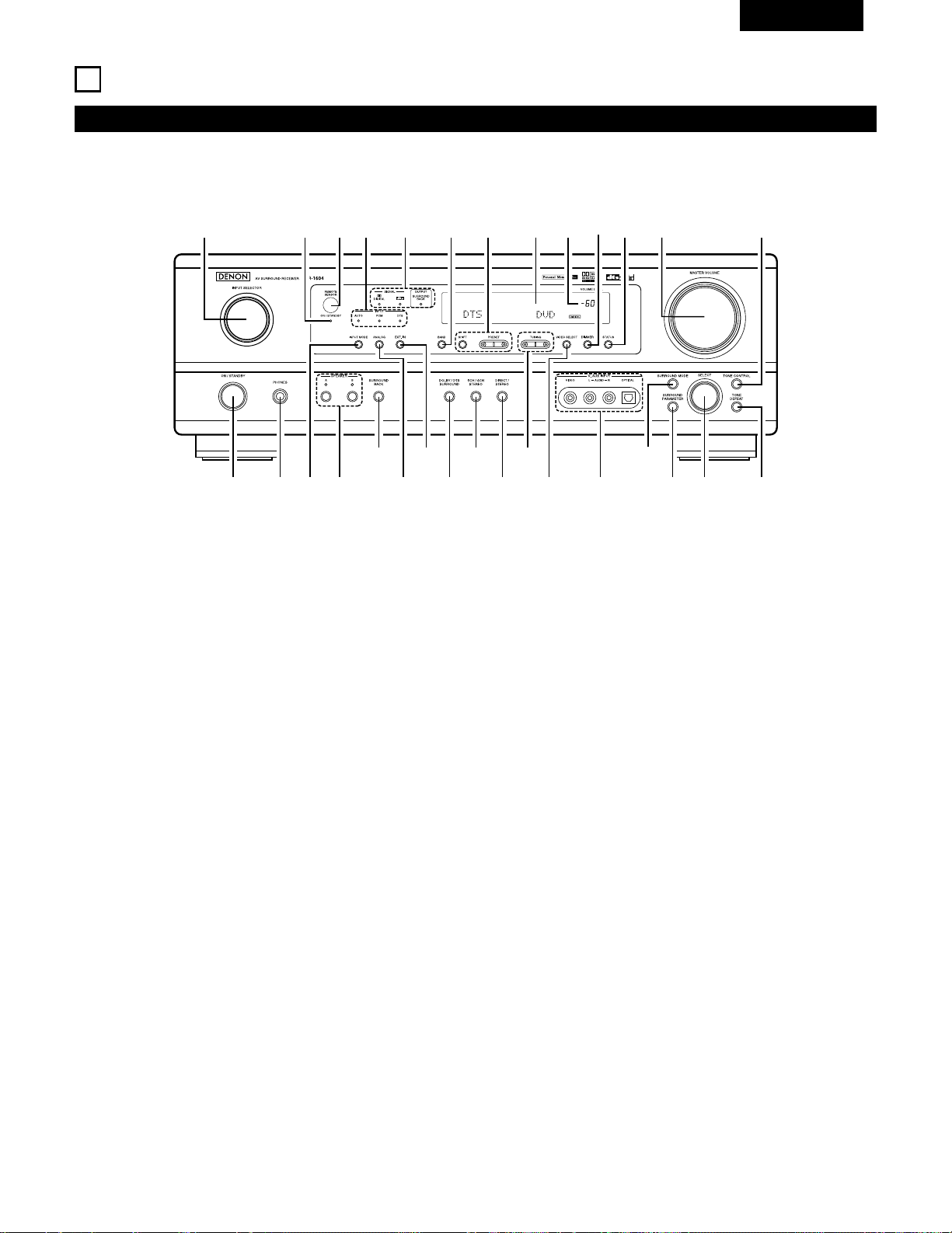
65
FRANCAIS
5
NOMENCLATURE ET FONCTIONS
Panneau avant
• Pour les détails sur les fonctions de ces pièces, se reporter aux pages données entre parenthèses ( ).
q wue ir
y
o!4t !1
@1@2
@3@4@5@6@7@8@9
!2 !3 !5 !6 !7!0
!8@0 !9#0
q
Interrupteur de mise en marche ...............................(77, 91, 110)
w
Prise de casque d’écoute (PHONES) ......................................(94)
e
Touche INPUT MODE................................................(92, 95, 102)
r
Touche SPEAKER A/B .....................................................(91, 113)
t
Touche SURROUND BACK ..................................................(102)
y
Touche ANALOG ...............................................................(92, 95)
u
Touche EXT. IN ..................................................................(92, 95)
i
Touche DOLBY/DTS SURROUND.............................(96, 98, 102)
o
Touche 5CH/6CH STEREO............................................(105, 108)
!0
Touche DIRECT/STEREO .......................................................(105)
!1
Touches TUNING D (augmentation) / H (diminution)............(111)
!2
Touche VIDEO SELECT ...........................................................(94)
!3
Prises V. AUX INPUT.........................................................(63, 70)
!4
Touche SURROUND MODE ............................................(93, 108)
!5
Touche SURROUND PARAMETER..................................(98, 106)
!6
Sélecteur de SELECT................................................(93, 98, 108)
!7
Touche TONE DEFEAT............................................................(93)
!8
Touche TONE CONTROL.........................................................(93)
!9
Commande MASTER VOLUME..............................................(93)
@0
Touche STATUS .......................................................................(94)
@1
Touche DIMMER.....................................................................(94)
@2
Témoin de volume principal (VOLUME LEVEL).......................(93)
@3
Affichage
@4
Touches de sélection de stations préréglées................(110, 112)
@5
Touche BAND........................................................................(111)
@6
Indicateurs type de signal (SIGNAL) ........................................(93)
@7
Indicateurs mode de entrée (INPUT) .......................................(93)
@8
Capteur de télécommande (REMOTE SENSOR) ....................(75)
@9
Indicateur de mise sous tension
#0
Sélecteur de source d’entrée..................................................(92)
Page 66

REMARQUE:
• Les touches rayées ne fonctionnent pas avec le AVR-1604/684.
(Rien ne se passe lorsqu’elles sont enfoncées.)
66
FRANCAIS
Unité de télécommande
• Pour les détails sur les fonctions de ces pièces, se reporter aux pages données entre parenthèses ( ).
Touches
d’ambiance ..........................(93, 96, 106)
Touches de
curseur...........................(76, 88, 96, 106)
Touche STATUS/DISPLAY ............(88, 94)
Touche de tonalité d’essai.................(96)
Emetteur de signaux
de télécommande..............................(75)
Touches de commande
MASTER VOLUME............................(93)
Touches POWER.............(77, 87~89, 91)
Touche MUTING................................(94)
Commutateurs de sélection
de mode..........................(76, 86~88, 90)
Système tuner/
touches Système.........(86, 89, 111, 112)
Touche SYSTEM SET UP/
SETUP....................................(76, 85, 88)
Sélecteurs de mode
d’entrée........................................(92, 95)
Sélecteurs de source
d’entrée...........................(87~90, 92, 98)
Touches SURROUND PARAMETER
.....................................................(88, 98)
Touche CH SELECT/
ENTER .............................(76, 88, 97, 99)
Touche SURROUBD BACK/
RETURN
.....................................(88, 102)
Sélecteur d’enceintes SPEAKER .......(91)
Touche DIMMER................................(94)Touche VIDEO SELECT......................(94)
Touches de système..............(86, 88, 89)
LED (Indicateur) ...........................(87, 90)
Page 67

67
FRANCAIS
6
A LIRE EN PREMIER
Ce récepteur d’ambiance AV doit être réglé avant l’utilisation selon les étapes suivantes.
7
RÉGLAGE DES SYSTÈMES D’ENCEINTE
Etape 3 (page 76 à 85)
Finalement, configurer le système.
Etape 2 (page 75)
Ensuite, insérer les piles dans la télécommande.
Etape 1 (page 67 à 74)
Choisir le meilleur emplacement pour l’installation des enceintes et la connexion des composants.
2 Disposition du système d’enceintes
Disposition de base du système
• Ce qui suit est un exemple de la disposition de base pour un système comprenant six systèmes d’enceinte et un moniteur de téléviseur:
Subwoofer Système d’enceintes centrales
Système d’enceintes d’ambiance
Systeme d’enceintes d’ambiance arrière
Système d’enceintes avant
Placer ces enceintes au niveau des flancs du
téléviseur ou de l’écran avec leurs surfaces avant
autant que possible en regard de l’avant de l’écran.
Page 68

68
FRANCAIS
8
CONNEXIONS
• Ne pas brancher le cordon d’alimentation avant d’avoir terminé
toutes les connexions.
• Toujours connecter correctement les canaux de gauche et de
droite (gauche avec la gauche et droite avec la droite).
• Insérer fermement les fiches. Des connexions incomplètes
peuvent générer des parasites.
•
N’utiliser les prises secteur (AC OUTLETS) que pour l’équipement
audio. Ne pas les utiliser pour un sèche-cheveux, etc.
• Remarquer que le groupement de cordons à fiches à broche
avec des cordons d’alimentation, ou le fait de les placer près
d’un transformateur provoque un bourdonnement ou un autre
bruit.
• Un bruit ou un bourdonnement peut être généré si un
composant audio connecté est utilisé indépendamment sans
mettre cet appareil sous tension. Dans ce cas, mettre cet
appareil sous tension.
Connexion des composants audio
LINE OUT
SURROUND
SUB WOOFER
CENTER
FRONT
LINE OUT
LINE OUT
LINE IN
R
OUTPUTINPUT
LRL
R
OUTPUT
L
R
L
R
L
R
L
L
R
L
R
R
L
R
L
L
R
DIGITAL AUDIODIGITAL AUDIO
INPUTOUTPUT
OPTICAL
B
++
INPUT
OUTPUT
AUX OUT
Connexion d’un lecteur de CD
Connecter les prises de sortie analogique
(ANALOG OUTPUT) du lecteur de CD aux prises
CD de cet appareil en utilisant les cordons à fiches
à broche.
Décodeurs avec sorties
analogiques 6 canaux, etc.
Prises numériques (DIGITAL)
Utiliser ces prises pour des connexions à l’équipement audio avec
sortie numérique. Se reporter à la page 84 pour les instructions
sur le réglage de cette borne.
PRISES SECTEUR
• Prises commutées (SWITCHED) (capacité totale 120 W (1 A.))
L’alimentation de ces prises est activée et désactivée par l’interrupteur de mise sous
tension (POWER) situé sur l’unité principale. Ces prises sont également commutées
lorsque l’alimentation est mise en veille (ON-STANDBY) à l’aide de la télécommande.
Lorsque l’AVR-1604/684 est en mode de veille, les prises sont désactivées. Ne jamais
connecter d’équipement dont la capacité totale est supérieure à 120 W (1 A).
REMARQUE:
N’utiliser les prises secteur (AC OUTLETS) que pour l’équipement audio. Ne jamais les
utiliser pour des sèche-cheveux, des télévisions ou d’autres appareils électriques.
Cordon d’alimentation
120 V CA, 60 Hz
Connecter le subwoofer de l’amplificateur interne à la borne de
subwoofer. (Se reporter à la page 73.)
Connexion d’une platine cassette
Connexions pour l’enregistrement:
Connecter les prises d’entrée d’enregistrement (LINE IN ou
REC) de la platine cassette aux prises de sortie (OUT)
d’enregistrement de cassette de cet appareil en utilisant les
cordons à fiches à broche.
Connexions pour la lecture:
Connecter les prises de sortie de lecture (LINE OUT ou PB)
de la platine cassette aux prises d’entrée (IN) de lecture de
cassette de cet appareil en utilisant les cordons à fiches à
broche.
Lecteur de CD
Platine cassette ou enregistreur de CD
• Utiliser des cordons à broche de câble de 75 Ω/ohms
(vendus séparément) pour les connexions coaxiales.
• Utiliser des câbles optiques (vendus séparément) pour les
connexions optiques.
Prises Subwoofer
Enregistreurs de CD, MD ou autre composant
équipé de prises de sortie numérique.
• Lorqu’une télécommande pièce-à-pièce vendue séparément
(DENON RC-616, 617 ou 618) est câblée et connectée entre la
PIECE PRINCIPALE et la UNE AUTRE PIECE, les appareils
pouvant être contrôlés par télécommande dans la piece
pribcipare peuvent être contrôlés depuis la UNE AUTRE PIECE
à l’aide de la télécommande.
Une autre pièce
RC-617 (Vendue séparément)
DETECTEUR INFRAROUGE
RC-616
(Vendue séparément)
RE-EMETTEUR
INFRAROUGE
Connexion des prises secteur
Prises d’extension pour utilisation
future.
Page 69

69
FRANCAIS
Connexion des composants vidéo
Pour connecter le signal vidéo, connecter en utilisant un câble de signal vidéo de 75 Ω/ohms. L’utilisation d’un mauvais câble peut entraîner une
baisse de la qualité du son.
IN
VIDEO
R
L
R
L
R
L
L
R
R OUT IN
AUDIO
VIDEO
OUT IN
LRL
R
L
R
L
R OUT
VIDEO
OUT
L
AUDIO
OUT
COAXIAL
DIGITAL
L
R
R OUT
VIDEO
OPTICAL
OUT
L
AUDIO
OUT
DIGITAL
L
R
B
B
Téléviseur ou tuner DBS
Lecteur de DVD ou lecteur de VDP
Moniteur de téléviseur
Connexion d’un téléviseur/tuner DBS
Téléviseur/DBS
• Connecter la prise de sortie vidéo (VIDEO OUTPUT) du
téléviseur ou du tuner DBS à la prise d’entrée de
téléviseur/tuner DBS (TV/DBS IN) (jaune) en
utilisant un cordon à fiches à broche coaxial vidéo de 75
Ω/ohms.
• Connecter la prise de sortie audio (AUDIO OUTPUT) du
téléviseur ou du tuner DBS à la prise d’entrée de
téléviseur/tuner DBS (TV/DBS IN) en utilisant
des cordons à fiches à broche.
AUDIO
VIDEO
Connexion d’un lecteur de DVD ou d’un lecteur de vidéo disque (VDP)
• Connecter la prise de sortie vidéo (VIDEO OUTPUT) du lecteur de DVD (lecteur de
vidéo disque) à la prise d’entrée de DVD/VDP (DVD/VDP IN) (jaune) en
utilisant un cordon à fiches à broche coaxial vidéo de 75 Ω/ohms.
• Connecter la prise de sortie audio analogique (ANALOG AUDIO OUTPUT) du lecteur
de DVD (lecteur de vidéo disque) à la prise d’entrée de DVD/VDP (DVD/VDP IN)
en utilisant des cordons à fiches à broche.
• Pour une meilleure qualité sonore, nous recommandons l’utilisation du lecteur de
DVD avec des connexions numériques plutôt qu’analogiques.
Les lecteurs de DVD et de VDP peuvent également être connectés aux bornes VCR.
AUDIO
VIDEO
Prise de sortie de moniteur (MONITOR
OUT)
• Connecter la prise d’entrée vidéo (VIDEO
INPUT) du téléviseur à la prise de sortie
de moniteur (MONITOR OUT) en
utilisant un cordon à fiches à broche
coaxial vidéo de 75 Ω/ohms.
VIDEO
REMARQUE:
La connexion d’un lecteur de VDP pourvu d’une prise de sortie
Dolby Digital RF.
• Prière d’utiliser un adaptateur disponible dans le commerce pour
la connexion de la prise de sortie Dolby Digital RF du lecteur de
VDP à la prise d’entrée numérique.
Se reporter au manuel d’instructions de l’adaptateur pour la
réalisation des connexions.
Magnétoscope
Connexions d’entrée/sortie vidéo:
• Connecter la prise de sortie vidéo (VIDEO OUT) du magnétoscope à la prise d’entrée de magnétoscope (VCR IN) (jaune) et la prise d’entrée vidéo (VIDEO
IN) du magnétoscope à la prise de sortie de magnétoscope (VCR OUT) (jaune) en utilisant les cordons à fiches à broche coaxial vidéo de 75 Ω/ohms.
Connexion des prises de sortie audio:
• Connecter les prises de sortie audio (AUDIO OUT) du magnétoscope aux prises d’entrée de magnétoscope (VCR IN) et les prises d’entrée audio (AUDIO
IN) du magnétoscope aux prises de sortie de magnétoscope (VCR OUT) en utilisant des cordons à fiches à broche.
AUDIO
AUDIO
VIDEO
VIDEO
Connexion des magnétoscopes
VIDEO OUT
VIDEO IN
VIDEO IN
AUDIO OUT
VIDEO OUT
VIDEO OUT
AUDIO OUT
AUDIO OUT
AUDIO IN
Page 70

70
FRANCAIS
Connexion d’un composant vidéo équipé de prises vidéo S
• Lors des connexions, se reporter également aux instructions d’utilisation des autres composants.
• Remarque à propos des prises en S
Les sélecteurs d’entrée pour les entrées en S et les entrées des prises à broches fonctionnent conjointement l’un avec l’autre.
• Précautions d’utilisation des prises en S
Les prises en S (entrée et sortie) de cet appareil et les prises à broche vidéo (entrée et sortie) ont des circuits indépendants, de façon à ce que
les signaux vidéo entrés par les prises en S soient envoyés uniquement des sorties des prises en S et les signaux vidéo des prises à broche
sont envoyés uniquement des sorties des prises à broche.
Lors de la connexion de cet appareil à un équipement équipé de prises en S, garder à l’esprit le point ci-dessus et faire les connexions en
respectant le mode d’emploi de chaque équipement correspondant.
IN
S-VIDEO
OUT
S-VIDEO
OUT
S-VIDEO
OUT IN
S-VIDEO
VIDEO IN
VIDEO OUT
VIDEO IN
VIDEO OUT
VIDEO OUT
B
B
Lecteur de DVD, Lecteur de VDP, etc.
Connexion d’un lecteur de DVD ou lecteur de
vidéodisque (VDP)
DVD/VDP
• Connecter la prise de sortie video S (S-VIDEO OUTPUT)
du lecteur de DVD ou lecteur de vidéodisque à la prise
d’entrée de DVD/VDP (DVD/VDP IN) [S-VIDEO] en
utilisant un cordon de connexion vidéo S.
Connexion d’un moniteur de téléviseur
MONITOR OUT
• Connecter la prise d’entrée vidéo en S (S-VIDEO
INPUT) du téléviseur ou du tuner DBS à la prise
MONITOR OUT en utilisant un corden à
prise en S.
S-VIDEO
Moniteur de téléviseur
Connexion d’un TV/tuner DBS
• Connecter la prise de sortie vidéo en S du téléviseur ou tuner
DBS à la prise TV/DBS IN en utilisant un vordon de
connexion à prise en S.
S-VIDEO
Téléviseur ou tuner
d’émission par satellite
Platine vidéo
Connexion des lecteurs vidéo
• Connecter la prise de sortie en S du lecteur vidéo à la prise
VCR IN et connecter la prise d’entrée en S du lecteur vidéo à prise
VCR OUT en utilisant de cordons à prise en S.
S-VIDEO
S-VIDEO
Connecter les entrées et sorties audio des composants la manière décrite à la page 69.
R VIDEO OUTOPTICALL
R VIDEO OUTL
OUTPUT
OUTPUT
LINE OUT
DIGITAL OUT
VIDEO OUT
VIDEO OUT
LINE OUT
L
R
L
R
L
R
Connexion d’un jeu vidéo
• Connecter les jacks de sortie du jeu vidéo au jacks V. AUX
INPUT de cet appareil.
Jeu vidéo
Caméscope
Connexion d’un caméscope
• Connecter les jacks de sortie du caméscope au jacks V. AUX
INPUT de cet appareil.
La borne V.AUX est recouverte d'un capuchon. Retirer ce
capuchon en cas d'utilisation. (Pour les instructions sur la
manière de retirer le capuchon, voir page 63.)
Page 71

71
FRANCAIS
VIDEO OUT
Y
CRCB
COMPONENT
YCRCB
VIDEO IN
COMPONENT
B
Connexion d’un composant vidéo équipé de prises vidéo (lecteur de DVD) (Composant - Y,
P
R/CR
, PB/CB) avec différence de couleur
• Lors des connexions, se reporter également aux instructions d’utilisation des autres composants.
• Les signaux entrés aux prises vidéo (composant) avec différence de couleur ne sont pas sortis par la prise de sortie vidéo (VIDEO) (jaune) ou la
prise de sortie vidéo S (S-VIDEO). De plus, les signaux vidéo entrés aux prises d’entrée vidéo (VIDEO) (jaune) et aux prises d’entrée vidéo S (SVIDEO) ne sont pas sortis aux prises vidéo (composant) avec différence de couleur.
• Certaines sources vidéo avec sorties de composants vidéo sont étiquetées Y, C
B, CR ou Y, Pb, Pr ou Y, R-Y, B-Y. Ces termes se rapportent tous
à la sortie avec différence de couleur des composants vidéo.
Lecteur de DVD
Connexion d’un lecteur de DVD
Prises d’entrée de DVD (DVD IN)
• Connecter les prises de sortie vidéo (COMPONENT VIDEO OUTPUT) (composant)
avec différence de couleur du lecteur de DVD à la prise d’entrée (COMPONENT DVD
IN) en utilisant des cordons avec fiche à broche vidéo coaxiaux de 75 Ω/ohms.
• De la même manière, une autre source vidéo avec sorties de composant vidéo telles
que tuner TV/DBS, etc., peut être connectée aux prises vidéo (composant) avec
différence de couleur TV/DBS.
Monitor TV
Connexion d’un moniteur de téléviseur
Prise de sortie de moniteur (MONITOR OUT)
• Connecter les prises d’entrée vidéo (COMPONENT VIDEO INPUT) (composant) avec
différence de couleur de téléviseur à la prise de sortie de moniteur de composant
(COMPONENT MONITOR OUT) en utilisant des cordons avec fiche à broche vidéo
coaxiaux de 75 Ω/ohms.
• Les prises d’entrée avec différence de couleur peuvent être
indiquées de manière différente sur certains téléviseurs,
moniteurs ou composants vidéo (“CR, CB et Y”, “R-Y, B-Y et Y”,
“Pr, Pb et Y”, etc.). Pour les détails, lire attentivement les
instructions d’utilisation incluses avec le téléviseur ou l’autre
composant.
Page 72

72
FRANCAIS
1
4
2
3
Connexion des bornes d’antennes
DIRECTION DE
STATION DE
RADIODIFFUSION
ANTENNE-CADRE AM
(Accessoire)
ANTENNE FM
TERRE
ANTENNE
EXTERIEURE AM
Antenne intérieure FM
(Accessoire)
CABLE
COAXIAL
DE
75 Ω/ohms
Ensemble d’antenne-cadre AM
Connecter aux
bornes d’antenne AM.
Plier dans la
direction inverse.
Défaire le noeud en
vinyle et sortir la
ligne de connexion.
a.Avec l’antenne sur
le haut de toute
surface stable.
b. Avec l’antenne
fixée au mur.
Monter
Trou d’installation
Monter au mur, etc.
Connexion des antennes AM
1. Appuyer sur
le levier.
2. Insérer le
conducteur.
3. Ramener le
levier.
Remarque à l’installateur de système de télédistribution:
Ce rappel est fourni pour attirer l’attention de l’installateur de
système de télédistribution sur l’article 820-40 du NEC qui
fournit des directives sur une bonne mise à la masse et, en
particulier, spécifie que la terre du câble doit être connectée
au système de mise à la masse du bâtiment, aussi près du
point d’entrée de câble que possible.
Remarques:
• Ne pas connecter simultanément deux antennes FM.
• Même si une antenne extérieure AM est utilisée, ne pas
déconnecter l’antenne-cadre AM.
• Vérifier que les bornes de fil d’antenne-cadre AM ne
touchent pas les parties métalliques du panneau.
Page 73

73
FRANCAIS
Connexions du système d’enceintes
• Connecter les bornes d’enceinte aux enceintes en respectant les polarités
(< au <, > au >). Si les polarités ne sont pas respectées, un son central
faible est entendu, l’orientation des divers instruments n’est pas correcte et
le sens de la direction du son stéréo est détérioré.
• Lors de la réalisation des connexions, prendre soin de ne mettre en contact
aucun des conducteurs individuels du cordon d’enceinte avec des bornes
adjacentes, avec des conducteurs d’autres cordons d’enceinte ou avec le
panneau arrière.
Impédance d’enceinte
• Lorsque des systèmes d’enceinte A et B sont utilisés séparément, les
enceintes ayant une impédance de 6 à 16 Ω/ohms peuvent être connectées
pour une utilisation comme enceintes avant.
• Attention, lors de l’utilisation simultanée de deux paires de haut-parleurs ( A
+ B ) à l’avant, bien calculer l’impédance de la combinaison pour qu’elle soit
comprise entre 12 et 16 Ω/ohms.
• Des enceintes ayant une impédance de 6 à 16 Ω/ohms peuvent être
utilisées comme enceintes centre et ambiance et ambiance arriere.
• Le circuit de protection peut être activé si le système est reproduit pendant
une longue durée à un volume élevé lorsque des enceintes d’une impédance
inférieure à celle spécifiée sont connectées.
REMARQUE:
NE JAMAIS toucher les bornes d’enceinte lorsque l’ampli est sous
tension, sinon des décharges électriques risquent de se produire.
Connexion des bornes d’enceinte
1. Tourner dans le sens
contraire des aiguilles
d’une montre pour la
desserrer.
2. Insérer le cordon. 3. Tourner dans le sens
des aiguilles d’une
montre pour la
resserrer.
Connexion des fiches bananes
Tourner dans le sens des aiguilles d’une montre pour
serrer, puis insérer la fiche banane.
Fiche banane
1. Pousser la manette. 2. Insérer le cordon. 3. Tirer la manette.
(L)(R)
(L) (R)(L) (R)
Prise de connexion pour subwoofer avec
amplificateur incorporé (superwoofer), etc.
Pour obtenir un effet de lecture Dolby Digital,
utiliser une unité pouvant reproduire suffisamment
des fréquences inférieures à 80 Hz.
SYSTEME D’ENCEINTES D’AMBIANCE
SYSTEME D’ENCEINTES CENTRALES
• Précautions à prendre lors de la connexion des enceintes
Si une enceinte est placée près d’un téléviseur ou d’un moniteur vidéo, les couleurs de l’écran
peuvent être perturbées par le magnétisme de l’enceinte. Si cela se produit, déplacer
l’enceinte vers un endroit où cet effet ne se produit pas.
Système B
SYSTEME D’ENCEINTES AVANT
Système A
SYSTEME D’ENCEINTES D’AMBIANCE ARRIERE
Page 74

74
FRANCAIS
Circuit de protection
• Cet appareil est équipé d’un circuit de protection haute vitesse. Le but de ce circuit est de protéger les enceintes contre
des situations telles que lorsque la sortie de l’amplificateur de puissance est accidentellement court-circuitée et qu’un fort
courant passe, lorsque la température avoisinant l’appareil devient anormalement élevée, ou lorsque l’appareil est utilisé
à puissance élevée pendant une longue durée, ce qui entraîne une augmentation de température extrême.
Lorsque le circuit de protection est activé, la sortie des enceintes est coupée, et la DEL du témoin d’alimentation clignote.
Dans ce cas, suivre ces étapes: toujours couper l’alimentation de cet appareil, vérifier s’il y a des défauts de connexion
des cordons d’enceintes ou des câbles d’entrée, et attendre que l’appareil refroidisse, s’il est très chaud. Améliorer la
ventilation autour de l’appareil, et remettre sous tension.
Si le circuit de protection est à nouveau activé bien qu’il n’y ait pas de problème de câblage ou de ventilation autour de
l’appareil, couper l’alimentation, et contacter un centre d’entretien DENON.
Remarque sur l’impédance des enceintes
• Le circuit de protection peut être activé si l’appareil est utilisé pendant une longue durée à un volume élevé lorsque des
enceintes d’une impédance inférieure à celle spécifiée (par exemple, enceintes ayant une impédance inférieure à 4
Ω/ohms) sont connectées. Si le circuit de protection est activé, la sortie des enceintes est coupée. Couper l’alimentation
de l’appareil, attendre qu’il refroidisse, améliorer la ventilation autour de lui, puis remettre sous tension.
Page 75

75
FRANCAIS
9
UTILISATION DE LA TÉLÉCOMMANDE
En suivant la procédure expliquée ci-dessous, insérer les piles avant d’utiliser la télécommande.
Plage d’utilisation de la télécommande
Insertion des piles
Diriger la télécommande vers le détecteur de télécommande de la
manière indiquée sur le diagramme de gauche.
REMARQUES:
• La télécommande peut être utilisée à une distance directe
d’environ 7 m (23 pieds), mais cette distance diminue ou le
fonctionnement devient difficile s’il y a des obstacles entre la
télécommande et le détecteur de télécommande, si le détecteur
de télécommande est exposé à la lumière directe du soleil ou à une
autre lumière forte, ou si elle est actionnée d’un angle.
• Des enseignes au néon ou autres dispositifs émettant des
parasites type impulsion à proximité peuvent entraîner un mauvais
fonctionnement, par conséquent garder l’appareil aussi loin que
possible de ces dispositifs.
Approx. 7 m/23 pieds
30°
30°
w Insérer correctement les piles R6P/AA de
la manière indiquée sur le diagramme.
q Appuyer de la manière indiquée par la
flèche, et retirer en glissant.
e Refermer le couvercle.
REMARQUES:
• N’utiliser que des piles R6P/AA pour le remplacement.
• Vérifier que les polarités sont correctes. (Voir l’illustration à l’intérieur du compartiment à piles.)
• Retirer les piles si l’émetteur de la télécommande n’est pas utilisé pendant une longue période.
• Si des piles fuient, les jeter immédiatement. Eviter de toucher le matériel fuyant ou de le laisser entrer en contact avec un vêtement, etc.
Nettoyer à fond le compartiment à piles avant de mettre de nouvelles piles en place.
• Avoir des piles de remplacement à portée de main de manière à ce que les anciennes piles puissent être remplacées aussi vite que possible
quand il en est temps.
• Même si moins d’un an s’est écoulé, remplacer les piles par des neuves si l’appareil ne fonctionne pas lorsque l’unité de télécommande est
actionnées à proximité. (La pile fournie ne sert que pour la vérification du fonctionnement. La remplacer par une neuve le plus tôt possible.)
Page 76

76
FRANCAIS
10
INSTALLATION DU SYSTEME
• Une fois que toutes les connexions avec les autres composants AV ont été faites comme indiqué dans “CONNEXIONS” (voir pages 68 à 74),
faire les différents réglages décrits ci-dessous sur l’affichage.
Ces réglages sont nécessaires pour configurer le système de chambre d’écoute AV centré autour de cette unité.
Touche SYSTEM SETUP
Appuyer pour afficher la configuration du système sur l’affichage.
Touches CURSOR (•, ª, 0, 1)
Appuyez pour modifier ce qui est affiché.
Touche ENTER
Appuyer sur cette touche pour changer l’affichage.
Utiliser également cette touche pour terminer le réglage.
• Articles d’installation de système et valeurs par défaut (réglées à la livraison de l’usine)
Installation de système Valeurs par défaut
Speaker
Configuration
Subwoofer Mode
Digital In
Assignment
Entrer la combinaison des enceintes de votre système et leurs tailles
correspondantes (SMALL pour enceintes normales, LARGE pour pleine
taille, pleine gamme) pour automatiquement régler la composition des
signaux sortis par les enceintes et la réponse en fréquence.
Ceci affecte les prises d’entrées numériques pour les
différentes sources d’entrée.
Source
d’entrée
Entrée
numérique
Front Sp.
Large
Center Sp. Surround Sp. Subwoofer
Small Small Yes
CD DVD/VDP
COAXIAL OPTICAL 1
Delay Time
Ce paramètre sert à optimiser la synchronisation avec laquelle sont
produits les signaux audio des enceintes et du subwoofer en fonction
de la position d’écoute.
1
Régler le commutateur coulissant vers “AUDIO”.
2
Utiliser les touches suivantes pour installer le système:
Ceci sélectionne le subwoofer pour la lecture de signaux de
profondes graves.
Subwoofer mode = Normal
REMARQUE:
• La configuration du système n’est pas affichée lorsque “HEADPHONE ONLY” est sélectionnée.
Crossover
Frequency
Régler la fréquence (Hz) à un niveau inférieur à celui du son grave émis
par les diverses enceintes à partir du subwoofer.
80 Hz
Auto Surround
Mode
Réglage de la fonction du mode “Auto surround”. Auto Surround Mode = ON
Ext. In SW Level Régler le niveau de lecteur de canal de subwoofer Ext.In. Ext. In SW Level = +15 dB
TV/DBS
OPTICAL 2
Surround back Sp.
Small
Front L Center Surround Back
12 ft 12 ft 10 ft
Subwoofer
12 ft
Front R
12 ft
Surround L
10 ft
Surround R
10 ft
Front L Front R Center
0 dB 0 dB 0 dB
Test Tone
Ceci règle le volume des signaux émis par les enceintes et le subwoofer
pour les différents canaux afin d’obtemir des effets optimaux.
Surround L
0 dB
Surround R
0 dB
Surround Back
0 dB
Subwoofer
0 dB
Page 77

77
FRANCAIS
Avant de configurer le système
1
2
Appuyer sur la touche SYSTEM SETUP pour accéder aux réglages.
Vérifier que tous les composants sont en bon état, puis appuyez sur l’interrupteur de mise en marche
POWER sur l’unité principale ou la touche POWER sur la télécommande pour allumer l’alimentation.
3
Appuyer sur la touche ENTER ou (bas) pour passer à la configuration des haut-parleurs.
*SYSTEM SET UP
REMARQUE:
Appuyer à nouveau sur la touche SYSTEM pour mettre un terme à la configuration. La configuration du système peut être arrêtée à n’importe
quel stade. Tous les changements effectués jusqu’à ce stade seront pris en compte.
REMARQUE: Veuillez vous assurer que le bouton à glissière de la télécommande est en position “AUDIO”.
(Unité principale) (Unité de télécommande)
Configuration des haut-parleurs
1
Utiliser les touches (gauche) et (droit) pour sélectionner le type des haut-parleurs avant installés.
1 FRONT LARGE
LARGE
SMALL
touche (gauche) touche (droit)
Appuyer sur la touche ENTER ou (bas) pour passer au réglage des haut-parleurs centraux.
2
Utiliser les touches (gauche) et (droit) pour sélectionner le type des haut-parleur centraux installés.
2 CENTER SMALL
LARGE
SMALL
NONE
touche (gauche) touche (droit)
Appuyer sur la touche ENTER ou (bas) pour passer au réglage des haut-parleurs “surround”.
3
Utiliser les touches (gauche) et (droit) pour sélectionner le type des haut-parleurs surround installés.
3 SURR. SMALL
LARGE
SMALL
NONE
touche (gauche) touche (droit)
Appuyer sur la touche ENTER ou (bas) pour passer au réglage de l’enceinte d’ambiance arrière
(Surround Back).
REMARQUE:
• Lorsque l’option “Small” (petit) a été sélectionnée pour les haut-parleurs avant, l’option “Large” (grand) ne peut pas être sélectionnée pour les
haut-parleurs centraux.
(Initial)
(Initial)
(Initial)
REMARQUE:
• Lorsque l’option “Small” (petit) a été sélectionnée pour les haut-parleurs avants, l’option “Large” (grand) ne peut pas être sélectionnée pour
les haut-parleurs centraux.
Page 78

78
FRANCAIS
5
Utiliser les touches (gauche) et (droit) pour sélectionner le type de subwoofer installé.
5 S.WOOFER YES
YES
NO
touche (gauche) touche (droit)
Appuyer sur la touche ENTER ou (bas) pour entrer les réglages et passer au réglage de sortie de
graves (SUBWOOFER MODE)..
• Paramètres
Large…… Sélectionner ce paramètre en cas d’utilisation d’enceites pouvant entièrement reproduire des sons faibles inférieurs à 80 Hz.
Small…… Sélectionner ce paramètre en cas d’utilisation d’enceintes ne pouvant pas reproduire des sons faibles inférieurs à 80 Hz avec volume
suffisant. Lorsque ce réglage est sélectionné, les basses fréquences inférieures à 80 Hz sont affectées au subwoofer.
None…… Sélectionner ce paramètre lorsqu’aucune enceinte n’est installée.
Yes/No….Sélectionner “Yes” si un subwoofer est installé, Sélectionner “No” si un subwoofer n’est pas installé.
REMARQUE:
Sélectionner “Large” ou “Small” non pas en fonction de la taille physique de l’enceinte, mais en fonction de la capacité de reproduction de basses
à 80 Hz. Si vous ne pouvez pas déterminer le meilleur réglage, essayer en comparant le son lorsque réglé sur “Small” et lorsque réglé sur
“Large”, à un niveau qui n’endommagera pas les enceintes.
Précaution:
Lorsque le subwoofer n’est pas utilisé, toujours régler “Subwoofer = No”, sinon le son grave du canal avant est divisé en canal de subwoofer et
n’est pas reproduit dans certain mode.
(Initial)
4
Utiliser les touches (gauche) et (droit) pour sélectionner le type d’enceinte d’ambiance arrière.
4 S.BACK SMALL
LARGE
SMALL
NONE
touche (gauche) touche (droit)
Appuyer sur la touche ENTER ou (bas) pour passer au réglage du subwoofer.
(Initial)
REMARQUES:
• Lorsque petit “Small” a été sélectionné pour les enceintes surround, grand “Large” ne peut pas être sélectionné pour les enceintes
d’ambiance arrière.
Page 79

79
FRANCAIS
REMARQUES:
— Attribution de la gamme de signaux de basse fréquence —
• Les signaux produits d’un canal de subwoofer sont des signaux LTD (pendant la lecture de signaux Dolby Digital ou DTS) et la gamme de
signal de basse fréquence des canaux réglés sur “SMALL” dans la configuration de la gamme de signaux de basse fréquence des canaux
réglés sur “LARGE” sont produits à partir de ces canaux.
— Fréquence de croisement —
• Lorsque “Subwoofer” est réglé sur “Yes” (Oui) “dans la configuration des enceintes”, régler la fréquence (Hz) à un niveau inférieur à celui
du son grave émis par les diverses enceintes à partir du subwoofer (fréquence de croisement).
• Pour les enceintes réglées sur “Small (Faible)”, le son de fréquence inférieure à la fréquence de croisement est coupé et le son grave coupé
est envoyé à la place au subwoofer.
REMARQUE : Pour les systèmes d’enceintes ordinaires, nous recommandons de régler la fréquence de croisement à 80 Hz. Lors de
l’utilisation de petites enceintes, le réglage de la fréquence de croisement à une haute fréquence peut cependant améliorer
la réponse pour les fréquences proches de celle de croisement.
— Mode subwoofer —
• Le mode subwoofer n’est effectif que si les enceintes avant sont réglées sur “LARGE” et le subwoofer sur “YES” (Oui) dans le menu
“Configuration des haut-parleurs” (Voir page 77, 78).
Si les enceintes avant sont réglées sur “SMALL” ou le subwoofer sur “NO” (Non), le réglage du mode subwoofer n’a aucun effet sur la
lecture de la gamme des signaux de basse fréquence.
• Lorsque le mode de lecture “+MAIN” (+Principaux) est sélectionné, la gamme des signaux de basse fréquence des canaux réglés sur
“LARGE” est produite simultanément pour ces canaux et le canal subwoofer.
Dans ce mode de lecture, la gamme des signaux de basse fréquence remplit la pièce de manière plus régulière mais, suivant les dimensions
et la forme de cette pièce, des interférences peuvent se produirent à cause de la diminution du volume de la gamme des signaux de basse
fréquence.
• Lorsque le mode de lecture “NORM” est sélectionné, la gamme des signaux de basse fréquence des canaux réglés sur “LARGE” est
uniquement produite à partir de ces canaux. Dans ce mode de lecture il y a peu d’interférences de gamme basse fréquence dans la pièce.
• Essayez une source musicale ou un film et sélectionnez le mode de lecture qui procure le son de basse fréquence le plus fort.
Réglage du mode de subwoofer et de la fréquence de croisement
1
Utiliser les touches (gauche) et (droit) pour sélectionner le mode de sortie de graves.
6 SW MODE NORM
NORM +MAIN
touche (gauche) touche (droit)
Appuyer sur la touche ENTER ou (bas) pour entrer le réglage et commuter au réglage de la fréquence
de croisement.
(Initial)
2
Utiliser les touches (gauche) et (droit) pour sélectionner la fréquence de croisement.
7 CR.OVER 80Hz
80Hz
100Hz
120Hz 150Hz
touche (gauche) touche (droit)
Appuyer sur la touche ENTER ou (bas) pour entrer le réglage et passer au réglage SPEAKER DISTANCE.
(Initial)
Page 80

80
FRANCAIS
3
Utiliser les touches (gauche) et (droit) pour régler la distance entre le haut-parleur central et le centre
d’écoute.
10 CENTER 12ft
• Le chiffre de distance change d’un pied (ft) à chaque pression sur une des touches. Choisir la valeur la
plus proche de la distance mesurée.
Appuyer sur la touche ENTER ou (bas) pour passer au réglage du haut-parleur surround L.
Reglage de la distance des haut-parleurs
• Entrer la distance entre la position d’écoute et les différentes enceintes pour régler le temps de retard du mode d’ambiance.
Préparations:
Mesurer les distances entre la position d’écoute et les enceintes (L1 à L5) sur le diagramme de
droite).
L1: Distance entre l’enceinte centrale et la position d’écoute
L2: Distance entre les enceintes avant et la position découte
L3: Distance entre les enceintes d’ambiance et la position d’écoute
L4: Distance entre les enceintes d’ambiance arrière et la position d’écoute
L5: Distance entre le subwoofer et la position d’écoute
ATTENTION:
Il est à noter que la différence de distance pour chaque enceinte doit être de 15 ft (4.5 m) ou moins.
REMARQUE:
• Pas de réglage lorsque “None” a été sélectionné pour la Configuration d’Enceinte.
L1
L2
L5
L3
L4
Centre FRFL
Subwoofer
SL
Position d’écoute
SR
SB
1
Utiliser les touches (gauche) et (droit) pour régler la distance entre les haut-parleur avant L et le
centre d’écoute.
8 FRONT L 12ft
• Le chiffre de distance change d’un pied (ft) à chaque pression sur une des touches. Choisir la valeur la
plus proche de la distance mesurée.
Appuyer sur la touche ENTER ou (bas) pour passer au réglage du haut-parleur avant R.
2
Utiliser les touches (gauche) et (droit) pour régler la distance entre les haut-parleur avant R et le
centre d’écoute.
9 FRONT R 12ft
• Le chiffre de distance change d’un pied (ft) à chaque pression sur une des touches. Choisir la valeur la
plus proche de la distance mesurée.
Appuyer sur la touche ENTER ou (bas) pour passer au réglage du haut-parleur central.
Page 81

81
FRANCAIS
6
Utiliser les touches (gauche) et (droit) pour régler la distance des enceintes ambiance arrirè à la
position d’écoute.
13 S.BACK 10ft
• Le chiffre de distance change d’un pied (ft) à chaque pression sur une des touches. Choisir la valeur la
plus proche de la distance mesurée.
Appuyer sur la touche ENTER ou (bas) pour passer au réglage du subwoofer.
4
Utiliser les touches (gauche) et (droit) pour régler la distance entre les haut-parleurs surround L et
le centre d’écoute.
11 SURR.L 10ft
• Le chiffre de distance change d’un pied (ft) à chaque pression sur une des touches. Choisir la valeur la
plus proche de la distance mesurée.
Appuyer sur la touche ENTER ou (bas) pour passer au réglage du haut-parleur surround R.
5
Utiliser les touches (gauche) et (droit) pour régler la distance entre les haut-parleurs surround R et
le centre d’écoute.
12 SURR.R 10ft
• Le chiffre de distance change d’un pied (ft) à chaque pression sur une des touches. Choisir la valeur la
plus proche de la distance mesurée.
Appuyer sur la touche ENTER ou (bas) pour passer au réglage de l’enceinte d’ambiance arrière
(Surround Back).
7
Utiliser les touches (gauche) et (droit) pour régler la distance entre les haut-parleurs subwoofer et
le centre d’écoute.
14 SW 12ft
• Le chiffre de distance change d’un pied (ft) à chaque pression sur une des touches. Choisir la valeur la
plus proche de la distance mesurée.
Appuyer sur la touche ENTER ou (bas) pour entrer le réglage et passer au réglage de tonalité de test.
Page 82
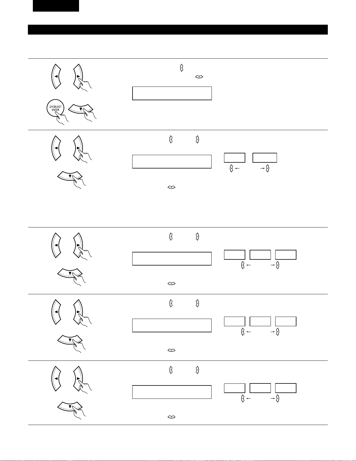
82
FRANCAIS
Réglage de la tonalité d’essai
• Utiliser ce réglage pour ajuster pour que le niveau de lecture entre les différents canaux soit égal.
• De la position d’écoute, écouter les tonalités d’essai produites par les enceintes pour ajuster le niveau.
• Le niveau peut également être directement ajusté de l’unité de télécommande. (Pour les détails, voir page 96.)
1
• Appuyer sur la touche (gauche) pour passer le mode de tonalité d’essai.
• Appuyer sur la touche ENTER ou (bas) pour passer au réglage d’entrée numérique (COAX).
15 T.TONE <YES
2
Utiliser les touches (gauche) et (droit) pour sélectionner le mode de tonalité d’essai.
T.TONE AUTO
AUTO
MANUAL
Appuyer sur la touche (bas) pour démarrer la tonalité de test.
touche (gauche) (right) button
3
Utiliser les touches (gauche) et (droit) pour régler la niveau de cannal du avant L.
AUTO-FL
-12dB
0dB +12dB
Appuyer sur la touche (bas) pour passer la niveau de cannal du central (mode manual).
touche (gauche) touche (droit)
4
Utiliser les touches (gauche) et (droit) pour régler la niveau de cannal du central.
AUTO-C
-12dB
0dB +12dB
Appuyer sur la touche (bas) pour passer la niveau de cannal du avant R (mode manual).
touche (gauche) touche (droit)
5
Utiliser les touches (gauche) et (droit) pour régler la niveau de cannal du avant R.
AUTO-FR
-12dB
0dB +12dB
Appuyer sur la touche (bas) pour passer la niveau de cannal du surround R (mode manual).
touche (gauche) touche (droit)
(Initial)
• Auto:
Ajuster le niveau pendant l’écoute des tonalités d’essai automatiquement produites par les différentes
enceintes.
• Manual:
Sélectionner l’enceinte par laquelle vous voulez produire la tonalité d’essai pour ajuster le niveau.
(Initial)
(Initial)
(Initial)
Page 83

83
FRANCAIS
6
Utiliser les touches (gauche) et (droit) pour régler la niveau de cannal du surround R.
AUTO-SR
-12dB
0dB +12dB
Appuyer sur la touche (bas) pour passer la niveau de cannal du enceinte d’ambiance arrière (mode
manual).
touche (gauche) touche (droit)
7
Utiliser les touches (gauche) et (droit) pour régler la niveau de enceinte d’ambiance arrière.
AUTO-SB
-12dB
0dB +12dB
Appuyer sur la touche (bas) pour passer la niveau de cannal du surround L (mode manual).
touche (gauche) touche (droit)
8
Utiliser les touches (gauche) et (droit) pour régler la niveau de surround L.
AUTO-SL
-12dB
0dB +12dB
Appuyer sur la touche (bas) pour passer la niveau de cannal du subwoofer (mode manual).
touche (gauche) touche (droit)
9
Utiliser les touches (gauche) et (droit) pour régler la niveau de subwoofer.
AUTO-SW
-12dB
0dB +12dB
Appuyer sur la touche ENTER pour terminer la tonalité d’essai.
touche (gauche) touche (droit)
10
Appuyer sur la touche ENTER ou (bas) pour passer au réglage d’entrée numérique (COAX).
(Initial)
(Initial)
(Initial)
(Initial)
Page 84

84
FRANCAIS
REMARQUE:
• TUNER, V. AUX ne peuvent pas être sélectionnés.
3
Utiliser les touches (gauche) et (droit) pour attribuer la fonction d’entrée connectée à la borne
d’entrée OPTICAL 2 (OPTICAL 2).
18 OPT2 TV
CD AUX DVD TV VCR CDR OFF
• Sélectionner “OFF” (arrêt) si aucun appareil n’est connecté.
Appuyer sur la touche ENTER ou (bas) pour commuter le réglage automatique du mode d’ambiance.
touche (gauche) (right) button
(Initial)
Réglage de l’assignation d’entrée numérique “Digital In Assignment”
Sélectionner le type d’appareil connecté aux bornes de l’entrée numérique.
1
Utiliser les touches (gauche) et (droit) pour attribuer la fonction d’entrée connectée à la borne
d’entrée COAXIAL (COAXIAL).
16 COAX CD
CD AUX DVD TV VCR CDR OFF
• Sélectionner “OFF” (arrêt) si aucun appareil n’est connecté.
Appuyer sur la touche ENTER ou (bas) pour passer au réglage d’entrée optique 1 (OPT1).
touche (gauche) touche (droit)
2
Utiliser les touches (gauche) et (droit) pour attribuer la fonction d’entrée connectée à la borne
d’entrée OPTICAL 1 (OPTICAL 1).
17 OPT1 DVD
CD AUX DVD TV VCR CDR OFF
• Sélectionner “OFF” (arrêt) si aucun appareil n’est connecté.
Appuyer sur la touche ENTER ou (bas) pour passer au réglage d’entrée optique 2 (OPT2).
touche (gauche) touche (droit)
(Initial)
(Initial)
Page 85

85
FRANCAIS
Apres avoir configure le système
1
Appuyer sur la touche SYSTEM SETUP pour terminer la configuration du système.
Ceci termine les opérations de configuration du système. Une fois la configuration terminée, il n’est plus nécessaire d’effectuer de changement
sauf si un nouvel élément est ajouté ou si la disposition des haut-parleurs est modifiée.
Réglage du mode Auto Surround
Pour les trois types de signaux d’entrée indiqués ci-dessous, le mode d’ambiance lu en dernier est sauvegardé dans la mémoire. A la prochaine
entrée du même signal, le mode d’ambiance mémorisé est sélectionné automatiquement et le signal est lu.
Noter que le réglage du mode d’ambiance est également mémorisé séparément pour la fonction d’entrée différente.
SIGNAL Mode d’ambiance automatique par défaut
q Signaux analogiques et de canal PCM STEREO
w Signaux à 2 canaux Dolby Digital, DTS ou autres format multicanaux Dolby PL
II Cinema
e Signaux multicanaux Dolby Digital, DTS ou d'autres format multicanaux Dolby ou DTS Surround
1
Utiliser les touches (gauche) et (droit) pour sélectionner le mode d’ambiance automatique.
19 AUTOSURR. ON
ON OFF
touche (gauche) touche (droit)
Appuyer sur la touche ENTER ou (bas) pour commuter le réglage du niveau SW Exit In.
(Initial)
Réglage du Ext. In SW Level
Sélectionner la méthode de lecture du signal d’entrée analogique connecté à la borne Ext.In.
1
Utiliser les touches (gauche) et (droit) pour sélectionner la lecture du niveau de canal Ext. In du
subwoofer.
20 EXT.IN SW +15
+00
+05
+10 +15
touche (gauche) touche (droit)
Appuyer sur la touche ENTER ou (bas) (down) si l’on veut démarrer les réglages depuis le début.
(Initial)
Page 86

86
FRANCAIS
Utilisation des composants audio DENON
• Mettre les différents composants sous tension avant de les utiliser.
1
2
3
Régler le commutateur de mode 1 sur “AUDIO”.
Régler le commutateur de mode 2 à la position du composant
à utiliser. (CD, CDR/MD ou platine cassette)
Actionner le composant audio.
• Pour les détails, se reporter aux instructions d’utilisation du composant.
Alors que cette télécommande est compatible avec une large gamme de composants contrôlés par infrarouges, certains modèles de
composants peuvent ne pas être actionnés avec cette télécommande.
1. Touches de lecteur et d’enregistreur de disques (CD)
et de système d’enregistrement de MD (CDR/MD)
3. Touches de système de tuner
2. Touches de système de platine cassette (TAPE)
3
2
1
3
6, 7 : Recherche manuelle (en arrière et en avant)
2 : Arrêt
1 : Lecture
8, 9 : Recherche automatique (repérage)
3 : Pause
DISC : Changer les disques
SKIP+ (uniquement pour changeurs de CD)
SHIFT : Changer la plage de canaux préréglés
CHANNEL : Augmentation/diminution de canal préréglé
+, –
TUNING : Augmentation/diminution de fréquence
+, –
BAND : Changer entre les bandes AM et FM
MODE : Changer entre auto et mono
MEMORY : Mémoire préréglée
6 : Rembobinage
7 : Avance rapide
2 : Arrêt
1 : Lecture en avant
0 : Lecture en arrière
A/B : Changer entre les platines A et B
11
UNITE DE TELECOMMANDE
REMARQUE:
• Le TUNER peut être utilisé lorsque le commutateur est placé en position “AUDIO”.
Page 87

87
FRANCAIS
Mémoire préréglée
DENON et d’autres fabricants de composants peuvent être actionnés en réglant la mémoire préréglée.
La télécommande peut être utilisée pour faire fonctionner les composants d’autres marques sans utiliser la fonction d’apprentissage en
enregistrant la marque du composant comme indiqué sur la liste de codes préréglés (page 122~126).
L’opération n’est pas possible pour certains modèles.
1
2
Régler le commutateur de mode 1 sur “AUDIO” ou “VIDEO”.
Régler le commutateur de mode 2 sur le composant à
enregistrer.
3
2
1
4
Régler sur AUDIO pour la position CD, platine cassette et
CDR/MD, régler sur VIDEO pour la position DVD/VDP,
DBS/CABLE, VCR ou TV.
3
Appuyer simultanément sur les touches ON/SOURCE et OFF.
• L’indicateur clignote.
4
5
En référence à la Liste des Codes
Préréglés inclue, utilisez les
boutons à numéro pour entrer le
code de préréglage (un numéro à 3
chiffres) pour le fabriquant du
composant dont vous vous voulez
emmagasiner les signaux en
mémoire.
Pour sauvegarder les codes d’un autre composant dans la
mémoire, répéter les étapes 1 à 4.
Les codes préréglés sont comme suit à la livraison de l’usine et après réinitialisation:
TV, VCR .....................................................HITACHI
CD, TAPE..................................................DENON
CDR/MD ...................................................DENON (CDR)
DVD/VDP ..................................................DENON (DVD)
DBS/CABLE..............................................ABC (CABLE)
REMARQUES:
• Les signaux des touches préréglées sont émis pendant le réglage de la mémoire préréglée. Pour éviter une utilisation accidentelle de la
télécommande, couvrir la fenêtre de l’émetteur pendant le réglage de la mémoire préréglée.
• En fonction du modèle et de l'année de fabriquation, cette fonction ne peut pas être utilisée pour certains modèles, même s'ils sont listés
en fabrique sur la liste inclue des codes de préréglage.
• Certains fabriquants utilisent plus d'un type de code de télécommande. Référez-vous à la liste incluse des codes de préréglage pour changer
le numéro et vérifier.
• La mémoire préréglée peut être réglée pour un composant seulement parmi CDR/MD, DVD/VDP et DBS/CABLE.
1
2
3
456
789
0
Page 88

88
FRANCAIS
Rappel des station avec les touches prétéglées
1
2
Régler le commutateur de mode 1 sur “AUDIO” ou “VIDEO”.
Régler le commutateur de mode 2 sur le composant à utiliser.
3
2
1
3
3
Régler sur AUDIO pour la position CD, platine cassette et
CDR/MD, régler sur VIDEO pour la position DVD/VDP,
DBS/CABLE, VCR ou TV.
1. Touches de système de lecteur
de vidéodisque numérique
(DVD, DVD SETUP)
POWER : Mise sous/attente tension
(ON/SOURCE)
OFF : Mise hors tension de DVD
DENON
6,7 : Recherche manuelle
(en avant et en arrière)
2 : Arrêt
1 : Lecture
8,9 : Recherche automatique
(au début de plage)
3 : Pause
0 ~ 9, +10 : Touche 10
skip + : Saut de disque
(pour changeur de DVD)
DISPLAY : Changer l’affichage
MENU : Menu
RETURN : Retour de menu
SETUP : Configuration
•, ª,
0, 1
: Curseur vers le haut, bas,
gauche et droite
ENTER : Enter réglage
2. Touches de système de lecteur
de vidéodisque (VDP)
POWER : Mise sous/attente tension
(ON/SOURCE)
6,7 : Recherche manuelle
(en avant et en arrière)
2 : Arrêt
1 : Lecture
8,9 : Recherche automatique
(repérage)
3 : Pause
0~9, +10 : Touche 10
3
Actionner le composant.
• Pour les détails, se reporter aux instructions d’utilisation du composant.
Certains modèles ne peuvent pas être actionnés avec cette unité de télécommande.
REMARQUE:
• Certains fabricants utilisent des
noms différents pour les
touches de commande de DVD,
donc se reporter également aux
instructions de télécommande
de ce composant.
Page 89

89
FRANCAIS
3. Touches de système de platine
vidéo (VCR)
4. Touches de système de tuner
d’émission par satellite (DBS) et
de télédistribution (CABLE)
POWER : Mise sous/attente tensiony
(ON/SOURCE)
6,7 : Recherche manuelle
(en avant et en arrière)
2 : Arrêt
1 : Lecture
3 : Pause
Channel +, – : Canaux
POWER : Mise sous/attente tension
(ON/SOURCE)
MENU : Menu
RETURN : Retour de menu
•, ª,
0, 1
: Curseur vers le haut, bas,
gauche et droite
ENTER : Entrer
CHANNEL : Changer de canaux
+, –
0~9, +10 : Canaux
DISPLAY : Changer l’affichage
VOL +, – : Augmentation/baisse de
volume
5. Touches de système de TV avec
moniteur (TV)
POWER : Mise sous/attente tension
(ON/SOURCE)
MENU : Menu
RETURN : Retour de menu
•, ª,
0, 1
: Curseur vers le haut, bas,
gauche et droite
ENTER : Enter
CHANNEL : Changer de canaux
+, –
0~9, +10 : Canaux
DISPLAY : Changer l’affichage
TV/VCR : Changer entre TV et
magnétoscope
TV VOL : Augmentation/baisse de
+, – volume
REMARQUES:
• Pour ce composant CD, CDR, MD et TAPE, les touches peuvent être utilisées de la même manière que pour les composants audio DENON
(page 86).
• Le téléviseur peut être utilisé lorsque le commutateur est en position DVD/VDP, VCR, TV.
Page 90

90
FRANCAIS
Table 1
Tension de pénétration (Punch Through)
•“Punch Through” (tension de pénétration) est une fonction permettant d’utiliser les touches PLAY, STOP, MANUAL SEARCH et AUTO SEARCH
des composants CD, TAPE, CDR/MD ou VCR en mode DBS/CABLE ou TV. Le réglage par défaut est sur aucun composant.
1
2
Régler le commutateur de mode 1 sur “VIDEO”.
Régler le commutateur de mode 2 sur le composant à
enregistrer (DBS/CABLE ou TV).
3
2
1
4
3
3
Appuyer sim ultanément sur les touches DVD/VDP et TV.
• L’indicateur clignote.
4
Entrer le numéro du composant à
régler. (Voir le tableau 1).
1
2
3
456
789
0
CD
TAPE
CDR/MD
DVD/VDP
VCR
No setting
No.
1
2
3
4
5
0
Page 91

91
FRANCAIS
12
OPERATION
Avant l’utilisation
Préparatifs:
Vérifier que toutes les connexions sont bonnes.
1
Allumer l’alimentation.
Appuyer sur la touche ON/STANDBY sur l’unité principale ou
sur la touche ON/SOURCE sur la télécommande pour la
mettre sous tension.
2
Sélectionner les enceintes avant.
Appuyer sur le commutateur d‘enceinte A ou B pour activer
l’enceinte.
(Unité principale) (Unité de télécommande)
• ON/STANDBY (sous tension/attente)
Lorsqu’on appuie sur la touche, l’alimentation s’allume et
l’affichage s’éclaire pendant environ une seconde.
Lorsqu’on appuie encore, l’alimentation s’éteint, le mode
de veille est mis et l’affichage s’éteint.
Quelques secondes s’écoulent entre le moment où
l’interrupteur de mise sous tension a été mis en position
“ON” et le début d’émission de son. Ceci est dû au circuit
de mise en sourdine qui évite le bruit lors de la mise sous
et hors tension.
(Unité principale) (Unité de télécommande)
• Le réglage A, B de l’enceinte frontale peut également être
modifié à l’aide de la touche SPEAKER de la télécommande.
1 2
1
2
Page 92

92
FRANCAIS
Lecture de la source de programme analogique
3
1 2 5
Fonction de sélection de mode d’entrée
Différents modes d’entrée peuvent être sélectionnés pour les
différentes sources d’entrée. Les modes d’entrée sélectionnés pour
les sources d’entrée séparées sont sauvegardés dans la mémoire.
q AUTO (mode auto)
Dans ce mode, les types de signaux entrés dans les prises
d’entrée numérique et analogique pour la source d’entrée
sélectionnée sont détectés et le programme dans le décodeur
d’ambiance de cet appareil est sélectionné automatiquement à la
lecture. Ce mode peut être sélectionné pour toutes les sources
d’entrée autres que TUNER.
La présence ou l’absence de signaux numériques est détectée,
les signaux entrés vers les prises d’entrée numérique sont
identifiés et le décodage et la lecture sont automatiquement
effectués en format DTS, Dolby Digital ou PCM (stéréo 2 canaux).
Si aucun signal numérique n’est entré, les prises d’entrée
analogique sont sélectionnées.
Utiliser ce mode pour lire des signaux au format Dolby Digital.
w PCM (mode de lecture exclusive de signaux PCM)
Le décodage et la lecture ne sont effectués que lorsque des
signaux PCM sont entrés.
Romarquer que des parasites peuvent être générés en cas
d’utilisation de ce mode pour lire des signaux qui ne sont pas au
format PCM.
e DTS (mode de lecture exclusive de signaux DTS)
Le décodage et la lecture ne sont effectués que lorsque des
signaux DTS sont entrés.
r
ANALOG (mode de lecture exclusive de signaux audio analogiques)
Les signaux entrés vers les prises d’entrée analogique sont
décodés et joués.
t
EXT. IN (mode de sélection de prise d’entrée de décodeur externe)
Les signaux entrés vers les prises d’entrée de décodeur externe
sont reproduits sans passer par le circuit d’ambiance.
REMARQUE:
• Note that noise will be output when CDs or LDs recorded in DTS
Remarquez que du bruit va être émis lorsque des CD ou des LD
enregistrés en format DTS sont lus dans le mode “PCM”(lecture
calibré pour le signal PCM) ou “ANALOG” (lecture calibrée pour un
signal audio analogique). Choisissez le mode AUTO ou DTS
(lecture calibrée pour le signal DTS) quand vous lisez des
enregistrements de format DTS.
Remarques sur la reproduction d’une source encodée avec DTS
• Du bruit parasite peut apparaître arec amorce au début de
la lecture et pendant la recherche en cours de lecture d’un
DTS dans le mode automatique. Si cela se produit, écouter
les DTS dans un mode précis.
• Dans certains cas rares des bruits parasites peuvent se
produire lorsque vous arrêtez la lecture d'un DTS-CD ou
d'un DTS-LD.
5
1
3
2
1
Sélectionner la source d’entrée à jouer.
Exemple: CD
(Unité principale) (Unité de télécommande)
2
Sélectionner le mode d’entrée.
• Sélection du mode analogique
Appuyer sur la touche ANALOG pour passer à l’entrée
analogique.
(Unité de télécommande)
• Sélection du mode d’entrée externe (EXT. IN)
Appuyer sur EXT. IN (sur la touche EXT. IN de l’unité de
télécommande) pour changer l’entrée externe.
(Unité principale) (Unité de télécommande)
• Sélection des modes AUTO, PCM et DTS
Le mode change de la manière indiquée ci-dessous chaque
fois que la touche INPUT MODE button est enfoncée.
AUTO PCM DTS
(Unité principale)
(Unité principale) (Unité de télécommande)
Page 93

93
FRANCAIS
• Pour augmenter les graves ou les aiguës: Tourner la
commande dans le sens des aiguilles d’une montre. (Le
son de graves ou d’aiguës peut être augmenté jusqu’à +12
dB en étapes de 2 dB.)
• Pour diminuer les graves ou les aiguës: Tourner la
commande dans le sens des aiguilles d’une montre. (Le
son de graves ou d’aiguës peut être réduit jusqu’à –12 dB
en étapes de 2 dB.)
Pour sélectionner le mode surround alors
que vous réglez les paramètres surround,
l’annulation de tonalité ou la commande de
tonalité, appuyez sur la touche de mode
surround puis actionnez le sélecteur.
3
Sélectionner le mode de lecture.
Appuyer sur la touche SURROUND MODE, puis tourner le
sélecteur SELECT.
Exemple: Stereo
(Unité principale) (Unité de télécommande)
4
Commencer la lecture sur le composant sélectionné.
• Pour les instructions d’utilisation, se reporter au manuel du
composant.
5
Régler le volume.
(Unité principale) (Unité de télécommande)
Le niveau de volume est
affiché sur l’affichage de
niveau de volume
principal.
Le volume peut être ajusté dans la gamme de –70 à 0 à 18 dB, en
étapes de 1 dB. Cependant, lorsque le niveau de canal est réglé de
la manière décrite à la page 96, si le volume d’un canal est réglé à
+1 dB ou plus, le volume ne peut pas être ajusté jusqu’à 18 dB.
(Dans ce cas le volume maximum est ajusté à “18 dB — (valeur
maximale du niveau de canal)”.)
Mode d’entrée en cas de reproduction de sources DTS
• Du bruit sera sorti si des CD ou LD compatibles DTS sont
reproduits dans le mode “ANALOG” ou “PCM”.
En cas de reproduction de sources compatibles DTS, toujours
connecter le composant source aux prises d’entrée numérique
(OPTICAL/COAXIAL), et régler le mode d’entrée à “DTS”.
Affichage du mode d’entrée
ANALOGDIGITAL
DIGITAL
DIGITAL
ANALOG
AUTO
PCM
DTS
INPUT
AUTO
PCM
DTS
INPUT
AUTO
PCM
DTS
INPUT
AUTO
PCM
DTS
INPUT
• En mode AUTO
• En mode DIGITAL PCM
• En mode DIGITAL DTS
• En mode ANALOG
Un de ceux-ci s’allume selon le signal
d’entrée.
Affichage du signal d’entrée
SIGNAL
DIGITAL
DIGITAL
DIGITAL
SIGNAL
SIGNAL
• DOLBY DIGITAL
• DTS
• PCM
L’indicateur s’allume lorsque les signaux numériques
sont entrés de façon correcte. Si l’indicateur ne s’allume
pas, vérifier si le réglage des composants d’entrée numériques et
les connexions sont corrects et si le composant est sous tension.
DIGITAL
DIGITAL
REMARQUE:
• L’indicateur s’allume lors de la lecture de CD-ROMs
contenant des données autres que des signaux audio, mais
aucun son n’est entendu.
DIGITAL
Après le début de la lecture
[1] Réglage de la qualité sonore (tonalité)
1
La tonalité commute de la manière suivante chaque fois que
l’on appuie sur la touche TONE CONTROL.
BASS TREBLE
2
Lorsque le nom du volume devant être
réglé est sélectionné, tourner le bouton
SELECT pour régler le niveau.
32 1
(Unité principale)
(Unité principale)
3
Si vous ne voulez pas régler les graves ou les aiguës, activer
le mode d’invalidation de tonalité.
Les signaux ne traversent pas les
circuits des graves et aiguës, la
qualité sonore est donc plus élevée.
(Unité principale)
(Unité principale)
Page 94

94
FRANCAIS
Utilisation de la fonction de réduction d’intensité d’éclairage
• Utiliser cette fonction
pour modifier la
luminosité de l’affichage.
La luminosité de
l’affichage change en
quatre paliers (clair,
moyen, sombre et éteint)
en appuyant sur la touche DIMMER de la principale.
Affichage du panneau avant
• Les descriptions de
fonctionnement de
l’appareil sont également
affichées sur l’affichage
du panneau avant. De
plus, l’affichage peut être
commuté pour vérifier l’état de fonctionnement pendant la
lecture d’une source en appuyant sur la touche STATUS.
Lecture simultanée
Utiliser ce commutateur
pour contrôler une source
vidéo autre que la source
audio.
Appuyer répétitivement sur
la touche VIDEO SELECT
jusqu’à ce que la source désirée apparaisse sur l’affichage.
Cancelling simulcast playback.
• Sélectionner “SOURCE” à l’aide de la touche de sélection
vidéo.
• Commuter la source de programme au composant
connecté aux prises d’entrée vidéo.
[3] Désactivation provisoire du son (sourdine)
1
Utiliser cette fonction pour désactiver
momentanément la sortie audio.
Appuyer sur la touche MUTING.
Annulation du mode MUTING.
• Appuyer à nouveau sur la touche MUTING.
• La sourdine sera également annulée lorsque le MASTER
VOL est augmenté ou diminué.
[4]
Combinaison du son actuellement en cours de reproduction avec l’image désirée
1
[5] Vérification de la source programme actuellement en cours de reproduction, etc.
1
(Unité principale) (Unité de
télécommande)
1
1
2
2 1
[2] Ecoute avec casque REMARQUE:
Afin d’éviter une perte de l’ouïe, ne pas augmenter excessive ment le
niveau du volume lors de l’utilisation d’écouteurs.
1
Brancher la fiche de casque dans la
prise.
Connecter le casque à la prise
PHONES.
La sortie d’enceinte est coupée
automatiquement lorsque le casque
est connecté.
1
PHONES
(Unité principale) (Unité de
télécommande)
1
1
2
(Unité principale)
BRIGHT MEDIUM
OFF
DIM
(Unité de
télécommande)
(Unité de télécommande)
Page 95

95
FRANCAIS
Passer au mode d’entrée
externe (EXT. IN).
Appuyer sur EXT. IN pour
changer l’entrée externe.
Une fois cette sélection effectuée, les signaux d’entrée,
connectés aux canaux FL (avant gauche), FR (arrière droit), C
(central), SL (surround gauche) et SR (surround droit) des
jacks EXT.IN, sont envoyés directement aux systèmes
d’enceinte avant (gauche et droit), central et surround (gauche
et droit) sans passer par les circuits surround. En plus, l’entrée
du signal vers la prise SW (subwoofer) est dirigée sur la prise
PRE OUT SUBWOOFER.
Lecture en utilisant les prises d’entrée externe (EXT. IN)
1
(Unité principale)
(Unité de télécommande)
2
Annulation du mode d’ entrée externe
Pour annuler le réglage de l’entrée externe (EXT. IN), appuyez
sur le bouton INPUT MODE (AUTO, PCM, DTS) ou ANALOG
pour choisir le mode d’entrée souhaîté. (Voir page 92).
(Unité de télécommande)
(Unité principale)
• Lorsque le mode d’entrée est réglé sur l’entrée externe (EXT. IN) le
mode de lecture (DIRECT, STEREO, DOLBY/DTS SURROUND,
5/6CH STEREO ou DSP SIMULA TION) ne peut pas êtr e sélectionné.
REMARQUES:
• Dans les modes de lecture autres que le mode d’entrée externe,
les signaux connectés aux prises EXT. IN ne peuvent pas être
lus. En outre, les signaux ne peuvent pas être envoyés des
canaux non connectés aux prises d’entrée.
• Le mode d’entrée externe peut être réglé pour toute source
d’entrée. Pour regarder la vidéo tout en écoutant le son,
sélectionner la source d’entrée à laquelle est connecté le signal
vidéo, puis régler ce mode.
• SI le niveau de sortie du subwoofer semble trop élevé, réglez les
paramètres surround “SW ATT.” sur “ON”.
2 1
21
Enregistrement d’un programme source
(enregistrement de la source avec contrôle simultané)
1
Suivez les étapes 1 à 3 de la section “Lecture de la source
d’entrée”.
Les signaux de la source sélectionnée avec la touche de sélection de fonction sont transmis simultanément aux prises CDR/TAPE et VCR
REC OUT. Si un total de deux platines à cassettes/magnétoscopes sont connectés et réglés en mode d’enregistrement, la même source
peut être enregistrée simultanément sur chaque platine/magnétoscope.
REMARQUE:
• Le signal AUDIO IN sélectionné à l’aide de la sélecteur de source d’entrée est envoyé aux prises CDR/TAPE et VCR AUDIO OUT.
2
Démarrer l’enregistrement sur la platine à cassettes ou le
magnétoscope.
Pour les instructions, se rapporter aux instructions d’utilisation
de l’appareil.
Enregistrement simultané
Page 96

96
FRANCAIS
13
AMBIANCE
Avant la lecture utilisant la fonction d’ambiance
• Avant d’effectuer une lecture avec la fonction d’ambiance sonore, s’assurer d’utiliser auparavant les tonalités de test pour ajuster les réglages
niveaux de reproduction de chacune des enceintes. Ce réglage peut être effectué avec la télécommande (décrite) ci-dessous.
• Les réglages effectués avec les tonalités de test sont valables uniquement avec les modes DOLBY/DTS SURROUND.
Les niveaux de reproduction réglés pour des modes d’ambiance différents sont automatiquement mis en mémoire dans chacun des modes
d’ambiance.
1
Passer aux modes DOLBY/DTS SURROUND (Dolby Pro
Logic II ou Dolby Digital ou DTS).
2
Appuyer sur la touche TEST TONE.
3
Après la fin du réglage, appuyer à nouveau sur la touche TEST
TONE.
(Unité principale) (Unité de télécommande)
(Unité de télécommande)
Les tonalités d’essai sont envoyées
des différentes enceintes. Utiliser les
touches de réglage du volume des
canaux pour ajuster de telle façon que
le volume des tonalités d’essai soit
identique pour toutes les enceintes.
(Unité de télécommande)
1
2
2, 3
2
1
(Unité de télécommande)
REMARQUE: Veuillez vous assurer que le bouton à glissière
de la télécommande est en position “AUDIO”.
Page 97

97
FRANCAIS
• Après le réglage utilisant les tonalités d’essai, ajuster les niveaux des canaux en fonction des sources de lecture ou selon votre convenance
personnelle, comme décrit ci-dessous.
1
Sélectionner l’enceinte dont vous voulez ajuster le niveau.
Le canal change de la manière indiquée ci-dessous chaque
fois que la touche est enfoncée.
3
Ajuster le niveau de l’enceinte sélectionnée.
FL CNTR FR SR SB
SW SL
(Unité de télécommande)
(Unité de télécommande)
3
1, 2
3
REMARQUE: Veuillez vous assurer que le bouton à glissière
de la télécommande est en position “AUDIO”.
Le réglage par défaut du niveau de canal est de 0 dB.
Le niveau de reproduction de l'enceinte sélectionnée peut
être réglé sur une plage de valeurs allant de +12 à –12 dB
en utilisant les touches curseurs.
Le niveau de canal SW peut être éteint en diminuant d’un
cran à partir de –12dB.
OFF ´ -12 dB ´ 12 dB
2
(Unité de télécommande)
Page 98

98
FRANCAIS
Mode Dolby Surround Pro Logic
II
2
Sélectionner le mode Dolby Surround Pro Logic II.
S’allume
(Unité principale)
(Unité de télécommande)
3
Reproduire une source programme avec la marque
.
• Pour les instructions d’utilisation, se reporter aux manuels
des composants respectifs.
5, 74, 61 2
4, 6
5, 7
1
8
5, 7
2
4
Sélectionner le mode de paramètrage d'ambiance sonore.
MODE Dolby PL
CINEMA EQ
TONE DEFEAT
DEFAULT
MODE CINEMA
CINEMA EQ
TONE DEFEAT
DEFAULT
MODE MUSIC
PANORAMA
DIMENSION
CENTER WIDTH
DEFAULT
TONE DEFEAT
SURROUND BACK
SURROUND BACK
SURROUND BACK
ou ou
MODE musicMODE cinemaMODE DOLBY PL
1
Sélectionner la fonction se rapportant au composant que vous
désirez écouter.
Exemple: DVD
(Unité principale)
(Unité de télécommande)
Affichage
(Unité principale)
(Unité de télécommande)
Pour effectuer cette opération à l'aide de la télécommande,
vérifier que l'interrupteur de sélection de mode est réglé
sur “AUDIO”.
Affichage
5
Sélectionner le meilleur mode pour la souce.
(Unité principale)
(Unité de télécommande)
6
Régler les paramètres d'ambiance sonore selon le mode.
(Unité principale)
(Unité de télécommande)
• Le mode se commute à chaque pression sur la touche
comme indiqué ci-dessous.
• Le témoin Dolby Pro Logic s’allume.
Le mode Dolby Surround Pro
Logic IICinema ou Music peut
être choisi directement en
appuyant sur la touche CINEMA
ou MUSIC de la télécommande
pendant la lecture en mode
Dolby Surround Pro Logic II.
MODE cinema
Si vous voulez pas régler les graves ou les aiguës,
désactiver le mode d’invalidation de tonalité.
Page 99

99
FRANCAIS
REMARQUE:
• Pendant le réglage des paramètres, l’affichage va revenir à son
état d’origine plusieurs secondes après que le dernier bouton ait
été enfoncé, ce qui terminera le réglage.
7
Régler les paramétrages d'ambiance sonore.
• Réglage CINEMA EQ
ON OFF
ou ou
CINEMA EQ OFF
• Réglage PANORAMA
ON OFF
ou ou
PANORAMA OFF
• Réglage DIMENSION
0 3 6
ou ou
DIMENSION 3
• Réglage TONE DEFEAT
ON OFF
ou ou
TONE DEF. ON
• Réglage DEFAULT
YES Y/N NO
ou ou
DEFAULT Y/N
Sélectionner “Yes” pour retourner aux valeurs d'usine par
défaut.
8
Appuyer sur la touche SURROUND
PARAMETER pour terminer la mode de
paramètrage d’ambiance.
(Unité de télécommande)
Mode NEO:6
5, 74, 61 2
1
Sélectionner la fonction se rapportant au composant que vous
désirez écouter.
Exemple: DVD
(Unité principale)
(Unité de télécommande)
4, 6
5, 7
1
8
5, 7
2
Le mode DTS NEO:6 Cinéma ou
Musique peut être choisi
directement en appuyant sur la
touche CINEMA ou MUSIC sur
la télécommande pendant la
lecture en mode DTS NEO:6.
• Réglage CENTER WIDTH
0
CENTER WIDTH 3
4 7
ou ou
• Réglage SURROUND BACK SPEAKER
ON OFF
ou ou
SB: OFF
Page 100

100
FRANCAIS
3
Lire une source de programme.
4
Sélectionner le mode de paramètrage d'ambiance sonore.
MODE CINEMA
SURROUND BACK
DEFAULT
MODE MUSIC
SURROUND BACK
DEFAULT
CINEMA EQ CENTER IMAGE
TONE DEFEAT TONE DEFEAT
ou ou
MODE musicMODE cinema
(Unité principale)
(Unité de télécommande)
Pour effectuer cette opération à l'aide de la
télécommande, vérifier que l'interrupteur de sélection de
mode est réglé sur “AUDIO”.
Affichage
5
Sélectionner le meilleur mode pour la souce.
(Unité principale)
(Unité de télécommande)
6
Régler les paramètres d'ambiance sonore selon le mode.
(Unité principale)
(Unité de télécommande)
• Le mode se commute à chaque pression sur la touche
comme indiqué ci-dessous.
• Le mode se commute à chaque pression sur la touche
comme indiqué ci-dessous.
DOLBY PLII cinema
DTS NEO:6
2
Sélectionner le mode DTS NEO:6.
(Unité principale)
(Unité de télécommande)
7
Régler les paramétrages d'ambiance sonore.
• Réglage CINEMA EQ
ON OFF
ou ou
CINEMA EQ OFF
• Réglage CENTER IMAGE
0.0
C.IMAGE 0.2
0.2 0.5
ou ou
• Réglage DEFAULT
YES Y/N NO
ou ou
DEFAULT Y/N
Sélectionner “Yes” pour retourner aux valeurs d'usine par
défaut.
8
Appuyer sur la touche ENTER pour terminer la mode de
paramètrage d’ambiance.
(Unité de télécommande)
MODE cinema
• Réglage TONE DEFEAT
ON OFF
ou ou
TONE DEF. ON
• Réglage SURROUND BACK SPEAKER
ON OFF
ou ou
SB:ON
Si vous voulez pas régler les graves ou les aiguës,
désactiver le mode d’invalidation de tonalité.
 Loading...