

Page 1
FOR ENGLISH READERS PAGE 00, 02 ~ PAGE 029, 192
FÜR DEUTSCHE LESER SEITE 02, 30 ~ SEITE 056, 192
POUR LES LECTEURS FRANCAIS PAGE 02, 57 ~ PAGE 083, 192
PER IL LETTORE ITALIANO PAGINA 02, 84 ~ PAGINA 110, 192
PARA LECTORES DE ESPAÑOL PAGINA 2, 111 ~ PAGINA 137, 192
VOOR NEDERLANDSTALIGE LEZERS PAGINA 2, 138 ~ PAGINA 164, 192
FOR SVENSKA LÄSARE SIDA 2, 165 ~ SIDA 192
AV SURROUND RECEIVER
AVR
-
1603
OPERATING INSTRUCTIONS
BEDIENUNGSANLEITUNG
MODE D’EMPLOI
ISTRUZIONI PER L’USO
INSTRUCCIONES DE OPERACION
GEBRUIKSAANWIJZING
BRUKSANVISNING
Page 2
2
NOTE ON USE / HINWEISE ZUM GEBRAUCH
OBSERVATIONS RELATIVES A L’UTILISATION / NOTE SULL’USO
NOTAS SOBRE EL USO / ALVORENS TE GEBRUIKEN / OBSERVERA
• Avoid high temperatures.
Allow for sufficient heat dispersion
when installed on a rack.
• Vermeiden Sie hohe Temperaturen.
Beachten Sie, daß eine ausreichend
Luftzirkulation gewährleistet wird, wenn
das Gerät auf ein Regal gestellt wird.
• Eviter des températures élevées
Tenir compte d’une dispersion de
chaleur suffisante lors de l’installation
sur une étagère.
• Evitate di esporre l’unità a temperature
alte.
Assicuratevi che ci sia un’adeguata
dispersione del calore quando installate
l’unità in un mobile per componenti
audio.
• Evite altas temperaturas
Permite la suficiente dispersión del calor
cuando está instalado en la consola.
• Vermijd hoge temperaturen.
Zorg voor een degelijk hitteafvoer indien
het apparaat op een rek wordt geplaatst.
• Undvik höga temperaturer.
Se till att det finns möjlighet till god
värmeavledning vid montering i ett rack.
• Handle the power cord carefully.
Hold the plug when unplugging the
cord.
• Gehen Sie vorsichtig mit dem Netzkabel
um.
Halten Sie das Kabel am Stecker, wenn
Sie den Stecker herausziehen.
• Manipuler le cordon d’alimentation avec
précaution.
Tenir la prise lors du débranchement du
cordon.
• Manneggiate il filo di alimentazione con
cura.
Agite per la spina quando scollegate il
cavo dalla presa.
• Maneje el cordón de energía con
cuidado.
Sostenga el enchufe cuando
desconecte el cordón de energía.
• Hanteer het netsnoer voorzichtig.
Houd het snoer bij de stekker vast
wanneer deze moet worden aan- of
losgekoppeld.
• Hantera nätkabeln varsamt.
Håll i kabeln när den kopplas från eluttaget.
• Keep the set free from moisture, water,
and dust.
• Halten Sie das Gerät von Feuchtigkeit,
Wasser und Staub fern.
• Protéger l’appareil contre l’humidité,
l’eau et lapoussière.
• Tenete l’unità lontana dall’umidità,
dall’acqua e dalla polvere.
• Mantenga el equipo libre de humedad,
agua y polvo.
• Laat geen vochtigheid, water of stof in
het apparaat binnendringen.
• Utsätt inte apparaten för fukt, vatten
och damm.
• Unplug the power cord when not using
the set for long periods of time.
• Wenn das Gerät eine längere Zeit nicht
verwendet werden soll, trennen Sie das
Netzkabel vom Netzstecker.
• Débrancher le cordon d’alimentation
lorsque l’appareil n’est pas utilisé
pendant de longues périodes.
• Disinnestate il filo di alimentazione
quando avete l’intenzione di non usare il
filo di alimentazione per un lungo
periodo di tempo.
• Desconecte el cordón de energía
cuando no utilice el equipo por mucho
tiempo.
• Neem altijd het netsnoer uit het
stopkontakt wanneer het apparaat
gedurende een lange periode niet wordt
gebruikt.
• Koppla ur nätkabeln om apparaten inte
kommer att användas i lång tid.
• Do not obstruct the ventilation holes.
• Die Belüftungsöffnungen dürfen nicht
verdeckt werden.
• Ne pas obstruer les trous d’aération.
• Non coprite i fori di ventilazione.
• No obstruya los orificios de ventilación.
• De ventilatieopeningen mogen niet
worden beblokkeerd.
• Täpp inte till ventilationsöppningarna.
* (For sets with ventilation holes)
• Do not let foreign objects in the set.
• Keine fremden Gegenstände in das
Gerät kommen lassen.
• Ne pas laisser des objets étrangers dans
l’appareil.
• E’ importante che nessun oggetto è
inserito all’interno dell’unità.
• No deje objetos extraños dentro del
equipo.
• Laat geen vreemde voorwerpen in dit
apparaat vallen.
• Se till att främmande föremål inte
tränger in i apparaten.
• Do not let insecticides, benzene, and
thinner come in contact with the set.
• Lassen Sie das Gerät nicht mit
Insektiziden, Benzin oder
Verdünnungsmitteln in Berührung
kommen.
• Ne pas mettre en contact des
insecticides, du benzène et un diluant
avec l’appareil.
• Assicuratevvi che l’unità non venga in
contatto con insetticidi, benzolo o
solventi.
• No permita el contacto de insecticidas,
gasolina y diluyentes con el equipo.
• Laat geen insektenverdelgende
middelen, benzine of verfverdunner met
dit apparaat in kontakt komen.
• Se till att inte insektsmedel på
spraybruk, bensen och thinner kommer i
kontakt med apparatens hölje.
• Never disassemble or modify the set in
any way.
• Versuchen Sie niemals das Gerät
auseinander zu nehmen oder auf
jegliche Art zu verändern.
• Ne jamais démonter ou modifier
l’appareil d’une manière ou d’une autre.
• Non smontate mai, nè modificate l’unità
in nessun modo.
• Nunca desarme o modifique el equipo
de ninguna manera.
• Nooit dit apparaat demonteren of op
andere wijze modifiëren.
• Ta inte isär apparaten och försök inte
bygga om den.
ENGLISH DEUTSCH FRANCAIS ITALIANO ESPAÑOL NEDERLANDS SVENSKA
The lightning flash with arrowhead symbol, within an equilateral
triangle, is intended to alert the user to the presence of uninsulated
“dangerous voltage” within the product’s enclosure that may be of
sufficient magnitude to constitute a risk of electric shock to persons.
The exclamation point within an equilateral triangle is intended to alert
the user to the presence of important operating and maintenance
(servicing) instructions in the literature accompanying the appliance.
WARNING:
TO REDUCE THE RISK OF FIRE OR ELECTRIC SHOCK, DO NOT
EXPOSE THIS APPLIANCE TO RAIN OR MOISTURE.
CAUTION:
TO REDUCE THE RISK OF ELECTRIC
SHOCK, DO NOT REMOVE COVER (OR
BACK). NO USER-SERVICEABLE PARTS
INSIDE. REFER SERVICING TO QUALIFIED
SERVICE PERSONNEL.
• DECLARATION OF CONFORMITY
We declare under our sole responsibility that this
product, to which this declaration relates, is in
conformity with the following standards:
EN60065, EN55013, EN55020, EN61000-3-2 and
EN61000-3-3.
Following the provisions of 73/23/EEC, 89/336/EEC and
93/68/EEC Directive.
• ÜBEREINSTIMMUNGSERKLÄRUNG
Wir erklären unter unserer Verantwortung, daß dieses
Produkt, auf das sich diese Erklärung bezieht, den
folgenden Standards entspricht:
EN60065, EN55013, EN55020, EN61000-3-2 und
EN61000-3-3.
Entspricht den Verordnungen der Direktive 73/23/EEC,
89/336/EEC und 93/68/EEC.
• DECLARATION DE CONFORMITE
Nous déclarons sous notre seule responsabilité que
l’appareil, auquel se réfère cette déclaration, est
conforme aux standards suivants:
EN60065, EN55013, EN55020, EN61000-3-2 et
EN61000-3-3.
D’après les dispositions de la Directive 73/23/EEC,
89/336/EEC et 93/68/EEC.
• DICHIARAZIONE DI CONFORMITÀ
Dichiariamo con piena responsabilità che questo
prodotto, al quale la nostra dichiarazione si riferisce, è
conforme alle seguenti normative:
EN60065, EN55013, EN55020, EN61000-3-2 e
EN61000-3-3.
In conformità con le condizioni delle direttive 73/23/EEC,
89/336/EEC e 93/68/EEC.
QUESTO PRODOTTO E’ CONFORME
AL D.M. 28/08/95 N. 548
• DECLARACIÓN DE CONFORMIDAD
Declaramos bajo nuestra exclusiva responsabilidad que
este producto al que hace referencia esta declaración,
está conforme con los siguientes estándares:
EN60065, EN55013, EN55020, EN61000-3-2 y
EN61000-3-3.
Siguiendo las provisiones de las Directivas 73/23/EEC,
89/336/EEC y 93/68/EEC.
• EENVORMIGHEIDSVERKLARING
Wij verklaren uitsluitend op onze verantwoordelijkheid
dat dit produkt, waarop deze verklaring betrekking
heeft, in overeenstemming is met de volgende normen:
EN60065, EN55013, EN55020, EN61000-3-2 en
EN61000-3-3.
Volgens de bepalingen van de Richtlijnen 73/23/EEC,
89/336/EEC en 93/68/EEC.
• ÖVERENSSTÄMMELSESINTYG
Härmed intygas helt på eget ansvar att denna produkt,
vilken detta intyg avser, uppfyller följande standarder:
EN60065, EN55013, EN55020, EN61000-3-2 och
EN61000-3-3.
Enligt stadgarna i direktiv 73/23/EEC, 89/336/EEC och
93/68/EEC.
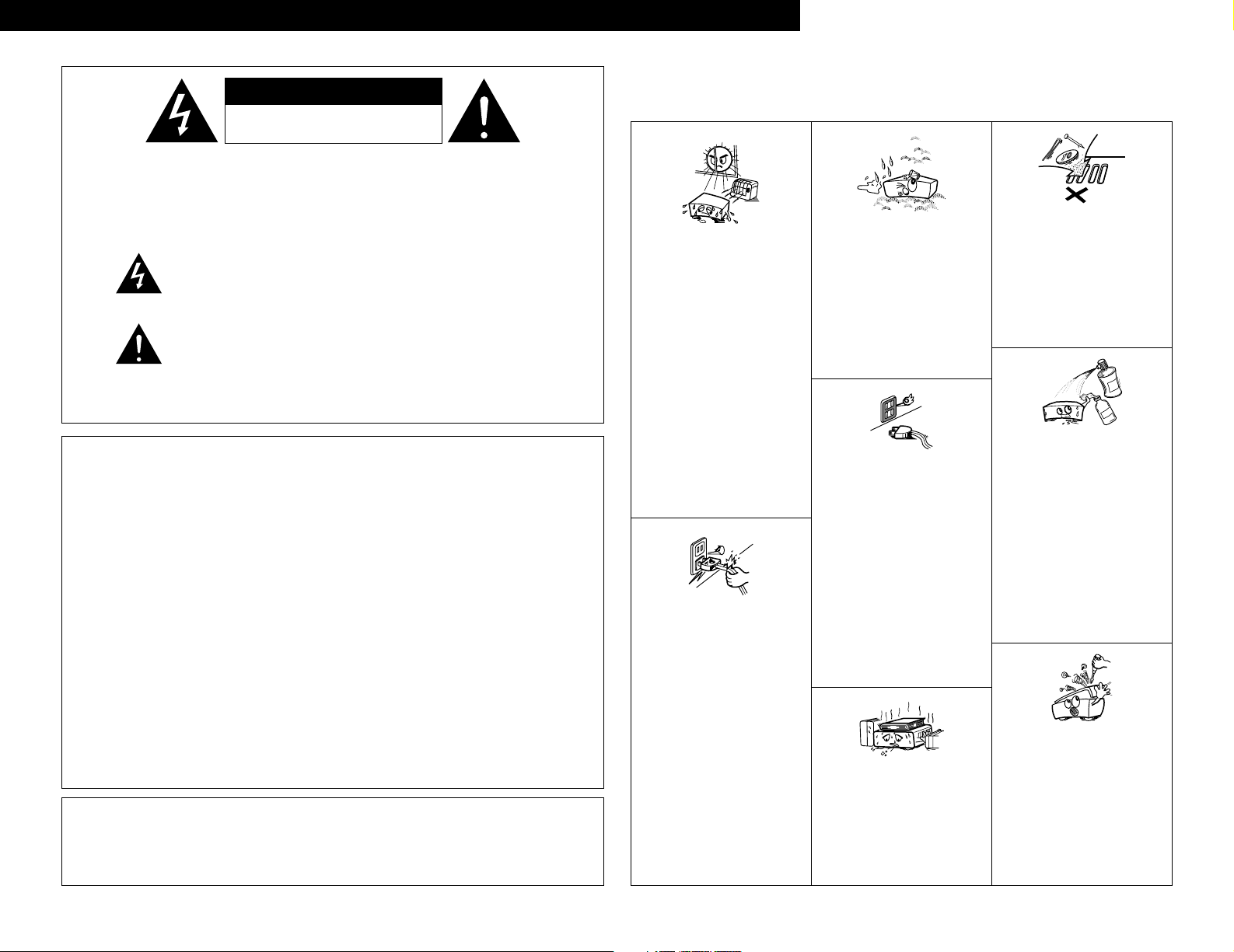
CAUTION
• The ventilation should not be impeded by covering the ventilation openings with items, such as newspapers, table-cloths,
curtains, etc.
• No naked flame sources, such as lighted candles, should be placed on the apparatus.
• Please be care the environmental aspects of battery disposal.
• The apparatus shall not be exposed to dripping or splashing for use.
• No objects filled with liquids, such as vases, shall be placed on the apparatus.
CAUTION
RISK OF ELECTRIC SHOCK
DO NOT OPEN
Page 3
3
ENGLISH
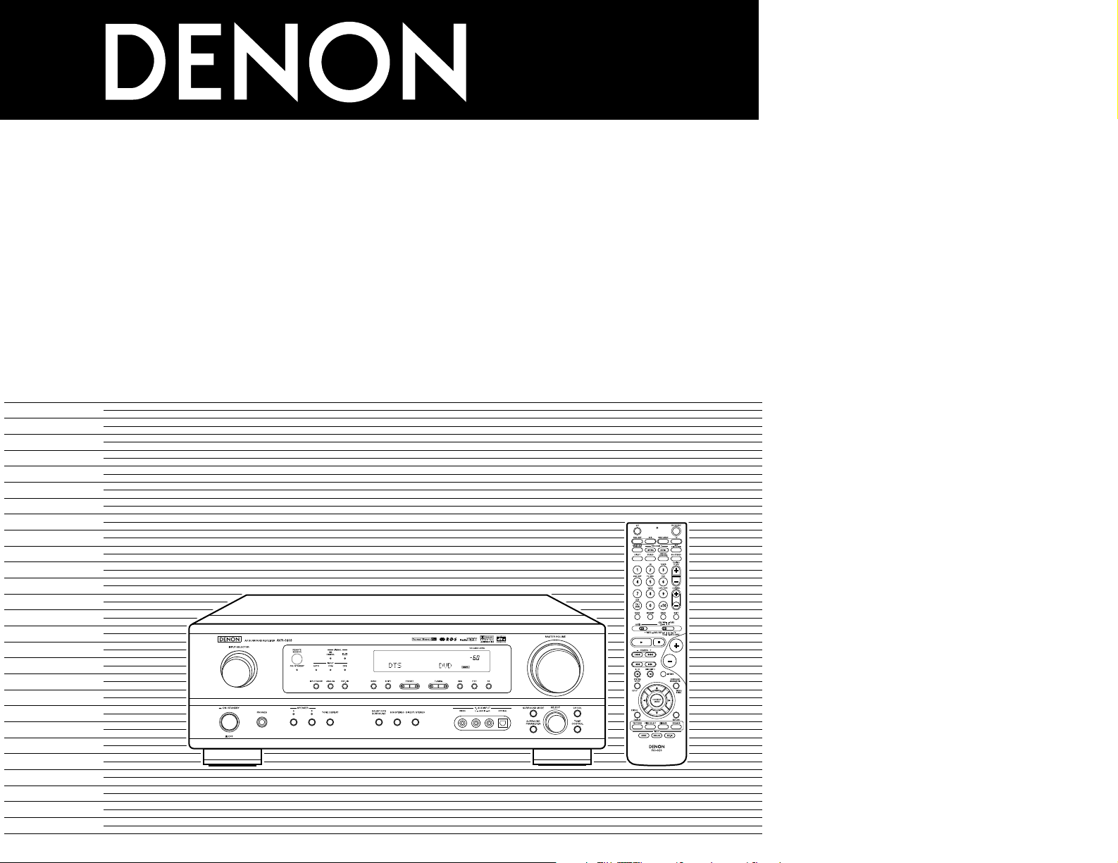
2 We greatly appreciate your purchase of the AVR-1603.
2 To be sure you take maximum advantage of all the features AVR-1603 has to offer, read these
instructions carefully and use the set properly. Be sure to keep this manual for future reference
should any questions or problems arise.
“SERIAL NO.
PLEASE RECORD UNIT SERIAL NUMBER ATTACHED TO THE REAR OF
THE CABINET FOR FUTURE REFERENCE”
2 INTRODUCTION
Thank you for choosing the DENON A/V Surround receiver. This remarkable component has been engineered to
provide superb surround sound listening with home theater sources such as DVD, as well as providing outstanding
high fidelity reproduction of your favorite music sources.
As this product is provided with an immense array of features, we recommend that before you begin hookup and
operation that you review the contents of this manual before proceeding.
TABLE OF CONTENTS
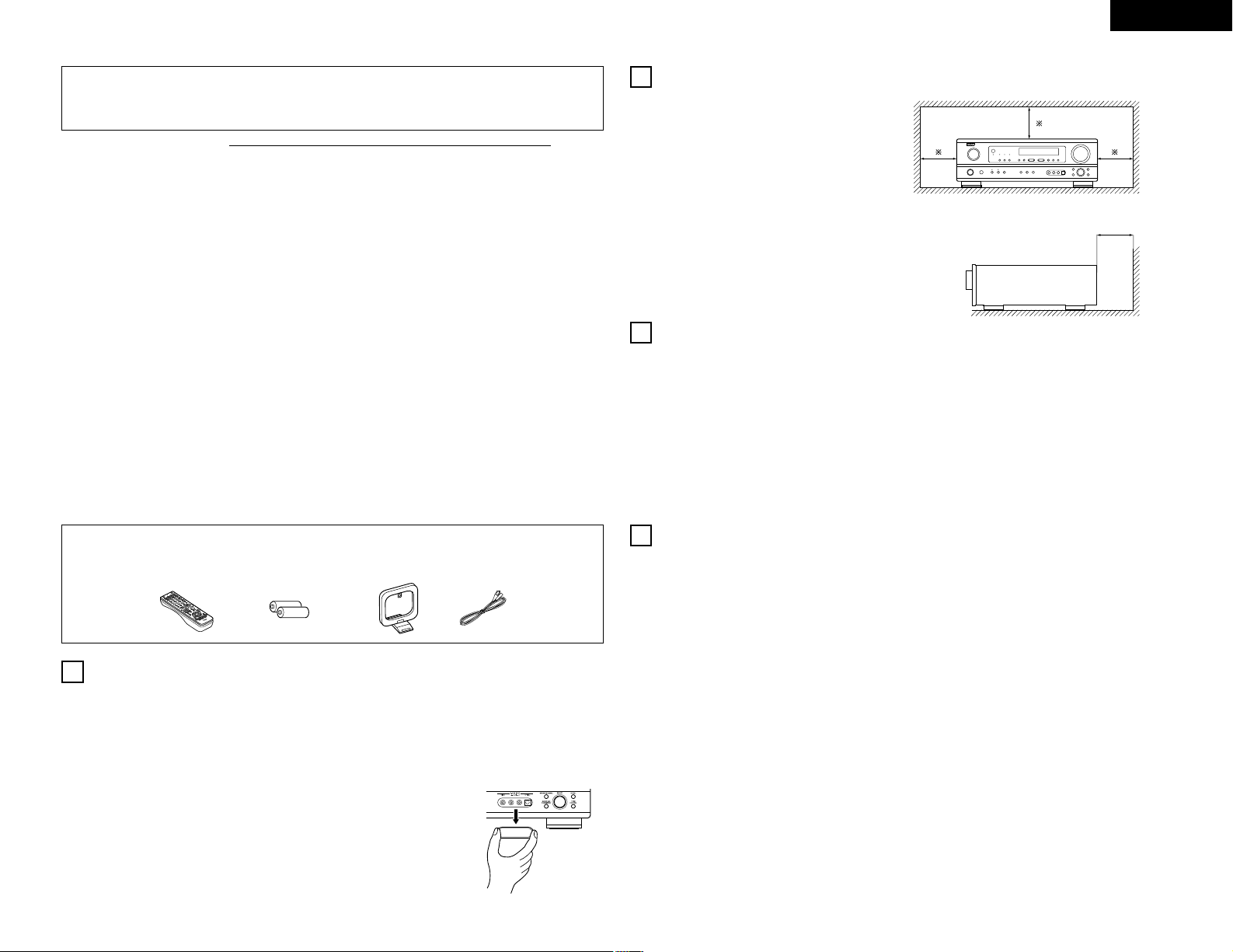
2 ACCESSORIES
Check that the following parts are included in addition to the main unit:
er t y
z
Before Using .......................................................3
x
Cautions on Installation .......................................3
c
Cautions on Handling ..........................................3
v
Features ..............................................................3
b
Part Names and Functions ..................................4
n
Read this First .....................................................5
m
Setting up the Speaker Systems.........................5
,
Connections..................................................5 ~ 8
.
Using the Remote Control Unit...........................9
⁄0
Setting up the system ................................9 ~ 12
⁄1
Remote Control Unit.................................13 ~ 15
⁄2
Operation ..................................................15 ~ 18
⁄3
Surround ...................................................18 ~ 20
⁄4
DSP Surround Simulation .........................21 ~ 23
⁄
5
Listening to the Radio...............................23 ~ 26
⁄6
Last Function Memory ......................................26
⁄7
Initialization of the Microprocessor ...................26
⁄8
Additional Information .................................27, 28
⁄9
Troubleshooting ................................................28
¤0
Specifications ....................................................29
List of Preset Codes.....................................192 ~ 194
q Operating instructions ……………………………1
w Service station list ………………………………1
e Remote control unit (RC-920) …………………1
r R6P/AA batteries ………………………………2
t AM loop antenna …………………………………1
y FM indoor antenna ………………………………1
1
BEFORE USING
Pay attention to the following before using this unit:
• Moving the set
To prevent short circuits or damaged wires in the
connection cords, always unplug the power cord and
disconnect the connection cords between all other
audio components when moving the set.
• Before turning the power operation switch on
Check once again that all connections are proper and
that there are not problems with the connection cords.
Always set the power operation switch to the
standby position before connecting and disconnecting
connection cords.
• Store this instructions in a safe place.
After reading, store this instructions along with the
warranty in a safe place.
• Note that the illustrations in this instructions may
differ from the actual set for explanation purposes.
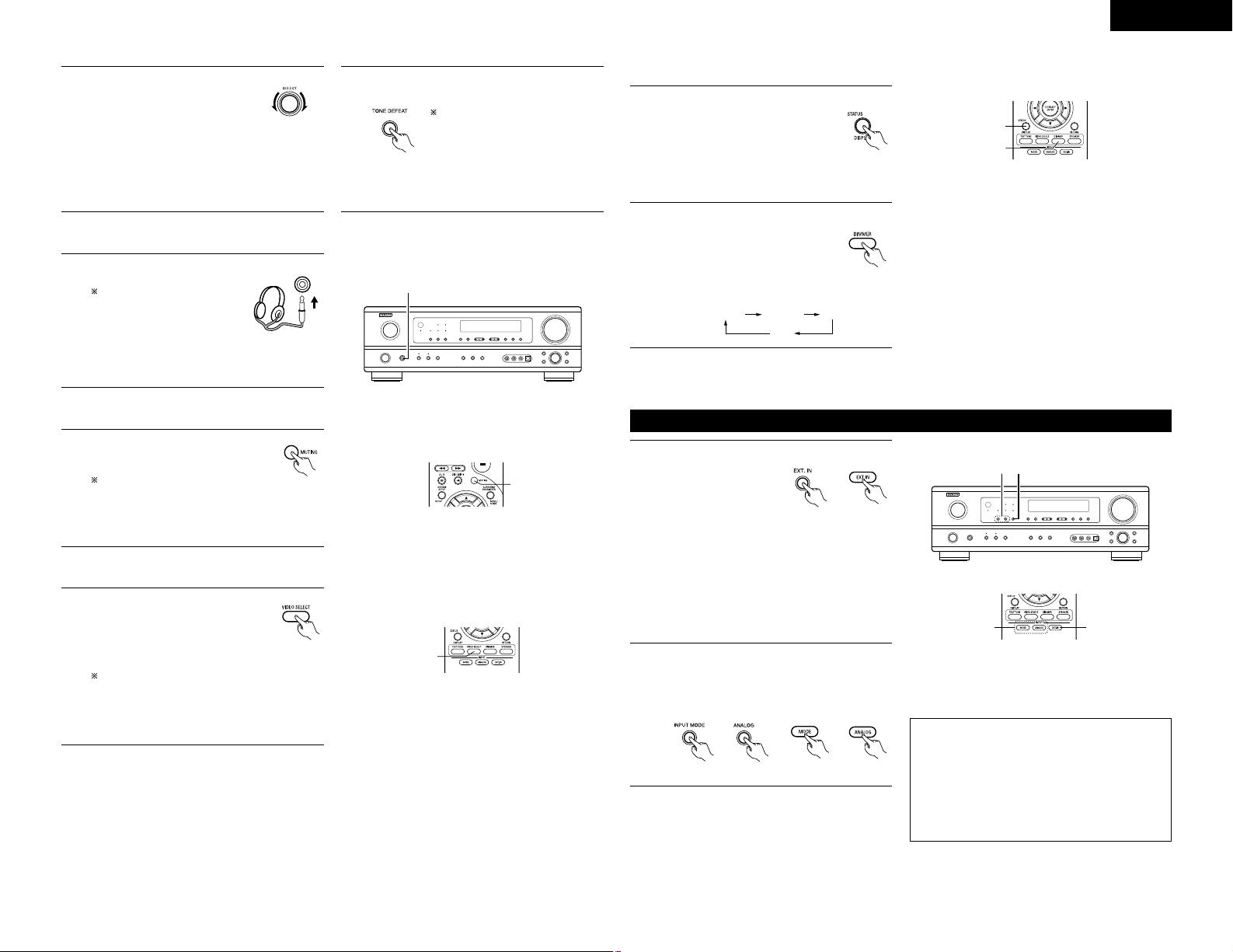
• V. AUX terminal
The AVR-1603's front
panel is equipped with a
V. AUX terminal. Remove
the cap covering the
terminal when you want
to use it.
Noise or disturbance of the picture may be generated
if this unit or any other electronic equipment using
microprocessors is used near a tuner or TV.
If this happens, take the following steps:
• Install this unit as far as possible from the tuner or
TV.
• Set the antenna wires from the tuner or TV away from
this unit’s power cord and input/output connection
cords.
• Noise or disturbance tends to occur particularly when
using indoor antennas or 300 Ω/ohms feeder wires.
We recommend using outdoor antennas and 75
Ω/ohms coaxial cables.
For heat dispersal, leave at least 10 cm of space
between the top, back and sides of this unit and the
wall or other components.
• Switching the input function when input jacks are
not connected
A clicking noise may be produced if the input function
is switched when nothing is connected to the input
jacks. If this happens, either turn down the MASTER
VOLUME control or connect components to the input
jacks.
• Muting of PRE OUT jack, HEADPHONE jack and
SPEAKER terminals
The PRE OUT jack, HEADPHONE jack and
SPEAKER terminals include a muting circuit.
Because of this, the output signals are greatly
reduced for several seconds after the power
operation switch is turned on or input function,
surround mode or any other set-up is changed.
If the volume is turned up during this time, the output
will be very high after the muting circuit stops
functioning. Always wait until the muting circuit turns
off before adjusting the volume.
• Whenever the power operation switch is in the
£ OFF or STANDBY state, the apparatus is still
connected on some AC line voltages.
Please be sure to unplug the cord when you leave
home for, say, a vacation.
1. Dolby Pro Logic II decoder
Dolby Pro Logic II is a new format for playing
multichannel audio signals that offers
improvements over conventional Dolby Pro Logic.
It can be used to decode not only sources recorded
in Dolby Surround but also regular stereo sources
into five channels (front left/right, center and
surround left/right). In addition, various parameters
can be set according to the type of source and the
contents, so you can adjust the sound field with
greater precision.
2. Dolby Digital decoder
Dolby Digital, a digital discrete system in which the
different channels are completely independent,
recreates “three-dimensional” sound fields (sounds
with a sense of distance, movement and position)
with no crosstalk between channels for greater
reality. In addition, the 5 channels (excluding the 0.1
channel for low frequency effects) have a playback
range extending to 20 kHz, the same as the range
of CDs, thus resulting in clearer, more richly
expressive sound.
3. DTS (Digital Theater Systems) decoder
DTS provides up to 5.1 channels of wide-range, high
fidelity surround sound, from sources such as laser
disc, DVD and specially-encoded music discs.
4. High performance DSP simulates 7 sound fields
Playback is possible in 7 surround modes: 5-channel
Stereo, Mono Movie, Rock Arena, Jazz Club, Video
Game, Matrix and Virtual. You can enjoy a variety of
sound effects for different movie scenes and
program sources even with stereo sources not in
Dolby Surround.
5. Personal Memory Plus function
Personal Memory Plus is an advanced version of
Personal Memory. With Personal Memory Plus, the
set automatically memorizes the surround mode,
channel volume, surround parameters, etc., for each
of the separate input sources.
6. Remote control unit with pre-memory function
This unit comes with a remote control unit equipped
with a pre-memory function. The remote control
command codes for DENON remote controllable AV
components as well as for LD players, video decks,
TVs, etc., of other major manufacturers are prestored
in the memory.
7. EXT. IN jack
This unit is equipped with EXT. IN jacks for use with
audio formats of the future.
2
CAUTIONS ON INSTALLATION
3
CAUTIONS ON HANDLING
4
FEATURES
10 cm or more
10 cm or more
wall
Page 4
ENGLISH
4
5
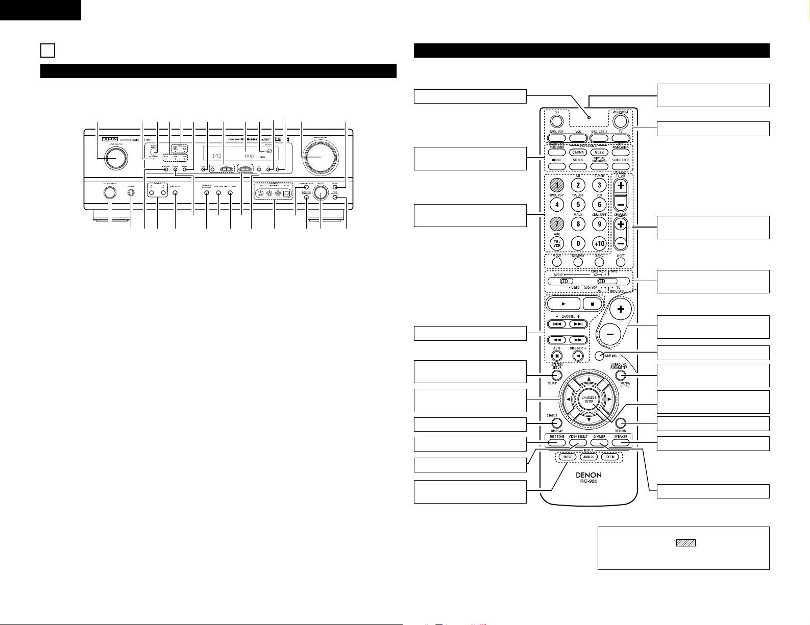
PART NAMES AND FUNCTIONS
Front Panel
• For details on the functions of these parts, refer to the pages given in parentheses ( ).
q w te ur
y i!3!0
@0@1
@2@3@4@5
@6
@7@8@9
!1 !2 !4 !5 !6o
!7!9 !8#0
q
Power operation switch ......................(10, 15, 23)
w
Headphones jack (PHONES) ...........................(17)
e
INPUT MODE button ..........................(16, 17, 19)
r
SPEAKER A/B buttons ..............................(15, 26)
t
TONE DEFEAT button.....................................(17)
y
ANALOG button ........................................(16, 17)
u
DOLBY/DTS SURROUND button..............(18. 19)
i
5CH STEREO button .......................................(20)
o
DIRECT/STEREO button .................................(20)
!0
TUNING UP/DOWN buttons ...........................(24)
!1
RDS button................................................(25, 26)
!2
V. AUX terminals ...........................................(3, 7)
!3
SURROUND MODE button.......................(16, 22)
!4
SURROUND PARAMETER button ............(19, 22)
!5
SELECT knob ....................................(16 ~ 19, 22)
!6
TONE CONTROL button .................................(16)
!7
CH VOL button................................................(18)
!8
MASTER VOLUME control .............................(16)
!9
RT button ........................................................(26)
@0
PTY button ......................................................(25)
@1
Master volume indicator (VOLUME LEVEL)....(16)
@2
Display
@3
Preset station select buttons..................(23 ~ 26)
@4
BAND button...................................................(24)
@5
EXT. IN button...........................................(16, 17)
@6
SIGNAL indicators ...........................................(16)
@7
INPUT mode indicators ...................................(16)
@8
Remote control sensor (REMOTE SENSOR) ....(9)
@9
Power operation indicator (ON/STANDBY)
#0
INPUT SELECTOR knob .......(16, 18, 19, 24 ~ 26)
Remote control unit
• For details on the functions of these parts, refer to the pages given in parentheses ( ).
LED (indicator).................(13, 15)
SURROUND
button..................(16, 18, 19, 21)
Test tone button ...................(18)
Input source selector buttons
............(13 ~16, 18, 19, 24 ~ 26)
Remote control signal
transmitter ..............................(9)
POWER buttons ...........(13 ~ 15)
Master volume control
buttons..................................(16)
MUTING button ....................(17)
Tuner system/
buttons .............(13, 14, 24 ~ 26)
SURROUND PARAMETER
button .....................(14, 19 ~ 22)
Mode select
switches ...................(9, 13 ~ 15)
SYSTEM SETUP/
SETUP button .............(9, 12, 14)
STATUS/DISPLAY button
..(14, 17)
Cursor buttons
...................(9 ~ 12, 14, 18 ~ 22)
DIMMER button....................(17)
CH SELECT (channel select)/
ENTER button ..............(9, 14, 18)
VIDEO SELECT button..........(17)
SPEAKER select button ........(15)
RETURN button ....................(14)
INPUT MODE select
buttons......................(16, 17, 19)
System buttons...............(13, 14)
NOTE:
• The shaded buttons do not function with
the AVR-1603. (Nothing happens when they are
pressed.)
Page 5
R
INTPUTOUTPUT
LRL
R
L
RLR
L
R
L
R
L
L
R
Step 3 (page 9 to 12)
Finally, setting up the system.
Step 2 (page 9)
Next, insert the batteries into the remote control unit.
ENGLISH
5
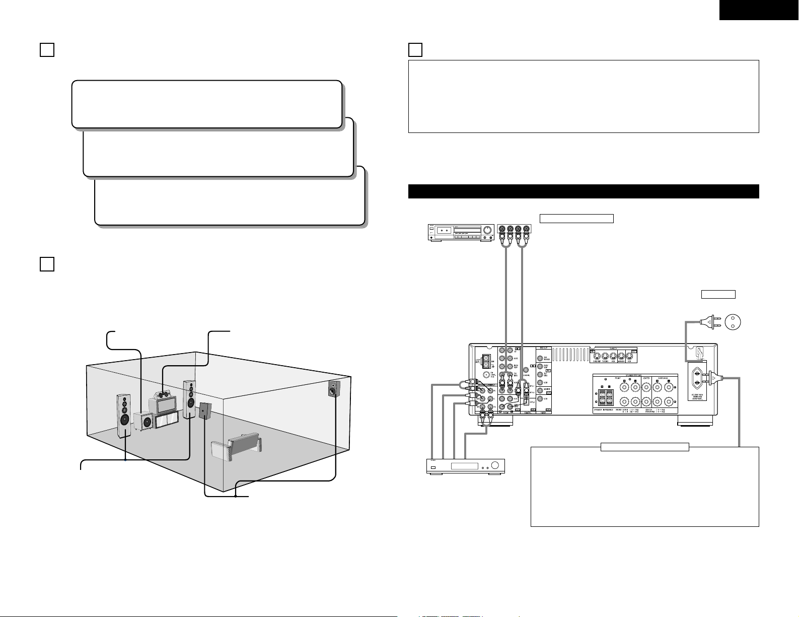
2 Speaker system layout
Basic system layout
• The following is an example of the basic layout for a system consisting of six speaker systems and a television
monitor:
Subwoofer
Center speaker system
Front speaker systems
Set these at the sides of the TV or
screen with their front surfaces as
flush with the front of the screen as
possible.
Surround speaker systems
6
READ THIS FIRST
This A / V surround Receiver must be setup before use. Following these steps.
Step 1 (page 5 to 8)
Choose the location to setup the speakers and connecting the components.
7
SETTING UP THE SPEAKER SYSTEMS
•
Do not plug in the power cord until all connections
have been completed.
•
Be sure to connect the left and right channels
properly (left with left, right with right).
•
Insert the plugs securely. Incomplete connections
will result in the generation of noise.
•
Use the AC OUTLET for audio equipment only. Do
not use them for hair driers, etc.
• Note that binding pin plug cords together with power
cords or placing them near a power transformer
will result in generating hum or other noise.
• Noise or humming may be generated if a connected
audio equipment is used independently without
turning the power of this unit on. If this happens,
turn on the power of this unit.
Connecting the audio components (1)
Decoders with 6-channel
analog outputs, etc.
Connecting a tape deck
Connections for recording:
Connect the tape deck’s recording input jacks (LINE IN or REC) to this unit’s tape
recording (OUT) jacks using pin plug cords.
Connections for playback:
Connect the tape deck’s playback output jacks (LINE OUT or PB) to this unit’s tape
playback (IN) jacks using pin plug cords.
8
CONNECTIONS
Tape deck or CD recorder
AC 230 V, 50 Hz
AC CORD
Connecting the AC OUTLET
AC OUTLET
• SWITCHED (capacity – 100 W)
The power to these outlets is turned on and off in conjunction with the POWER
switch on the main unit, and when the power is switched between on and standby
from the remote control unit.
No power is supplied from these outlets when this unit’s power is at standby. Never
connect equipment whose capacity is above 100 W.
NOTE:
Only use the AC OUTLET for audio equipment. Never use them for hair driers, TVs or
other electrical appliances.
• Analog recording of signals input to the AVR-1603 in digital format is not possible. To record in analog, also
connect the analog signals of the player to the AVR-1603’s analog input terminals.
• The AVR-1603’s OPTICAL OUT terminal is an optical digital output terminal for connection of a CD
recorder, MD recorder or other digital recording device. Use it for digital recording.
AUDIO IN
AUDIO OUT
FRONT
SUBWOOFER
CENTER
SURROUND
AUDIO OUT
Page 6
OPTICALCOAXIAL
R
L
DIGITAL AUDIODIGITAL AUDIO
RL
R
L
OUTPUT
OPTICAL
DIGITAL AUDIODIGITAL AUDIO
AUDIO OUT
OUTPUT
DIGITAL OUT
DIGITAL OUT
DIGITAL OUT
DIGITAL IN
OUTPUTBINPUT
ENGLISH
6
ROUT
VIDEO
OUT
L
AUDIO
OUT
DIGITAL
ROUT
VIDEO
OPTICAL
OUT
L
AUDIO
OUT
DIGITAL
R OUT IN
AUDIO
VIDEO
OUT IN
LRL
RLR
L
OPT.-1
R
L
R
L
R
L
L
R
L
R
R
L
IN
VIDEO
B
OPTICAL
B
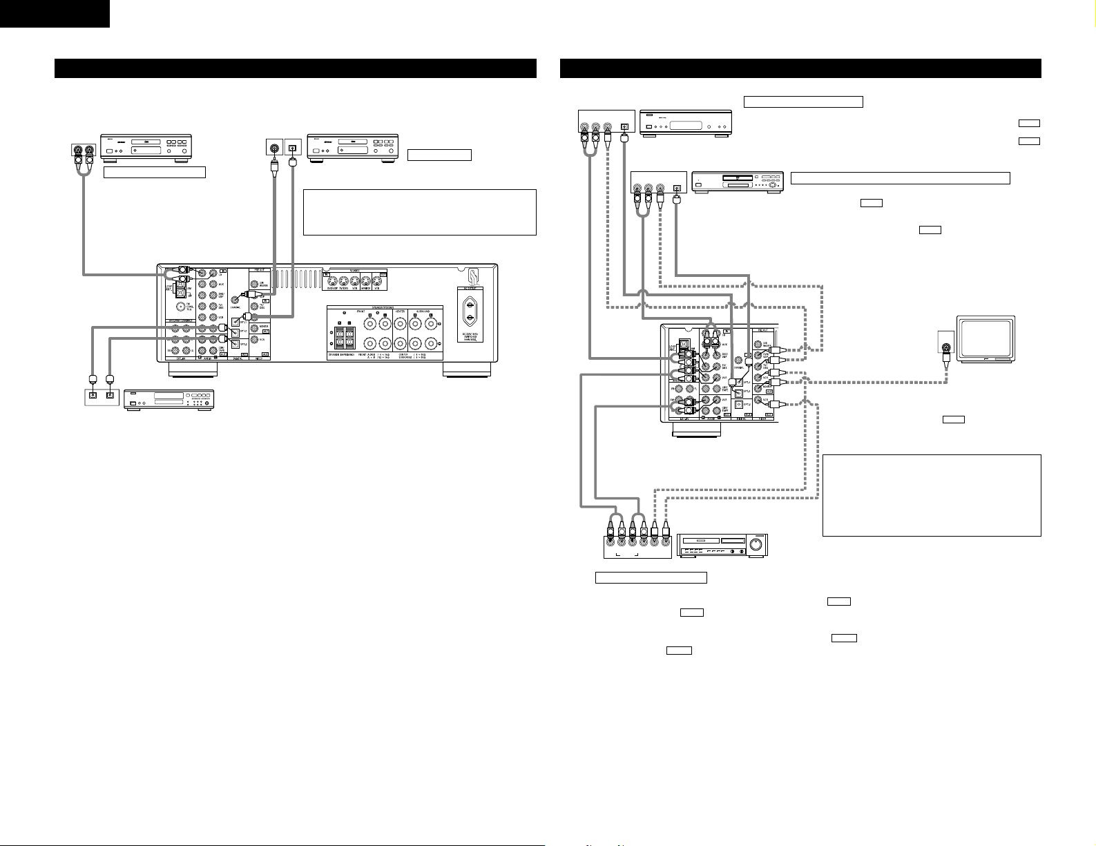
Connecting the video equipments
TV or DBS tuner
DVD player or video disc player (VDP)
Monitor TV
MONITOR OUT
• Connect the TV’s video input
jack (VIDEO INPUT) to the
MONITOR OUT jack
using a 75 Ω/ohms video
coaxial pin plug cord.
VIDEO
NOTE:
Connection of the video disc Player Equipped with Dolby
Digital RF (AC-3RF) Output Jack.
• Please use a commercially available adaptor when
connecting the Dolby Digital RF (AC-3RF) output jack of
the video disc player to the digital input jack.
Please refer to the instruction manual of the adapter
when making connections.
Connecting a DVD player or a video disc player VDP
• Connect the DVD player’s (video disc player’s) video output jack (VIDEO
OUTPUT) to the (yellow) DVD/VDP IN jack using a 75 Ω/ohms
video coaxial pin plug cord.
• Connect the DVD player’s (video disc player’s) analog audio output jacks
(ANALOG AUDIO OUTPUT) to the DVD/VDP IN jacks using pin
plug cords.
• For better sound quality, we recommend using the DVD player with
digital rather than analog connections.
DVD players and VDP can also be connected to the VCR terminals.
AUDIO
VIDEO
Connecting a video decks
Connecting a TV/DBS tuner
TV/DBS
• Connect the TV’s or DBS tuner’s video output jack (VIDEO OUTPUT) to the
(yellow) TV/DBS IN jack using a 75 Ω/ohms video coaxial pin plug cord.
• Connect the TV’s or DBS tuner’s audio output jacks (AUDIO OUTPUT) to the
TV/DBS IN jacks using pin plug cords.
AUDIO
VIDEO
VIDEO OUT
AUDIO OUT
AUDIO IN
VIDEO IN
AUDIO OUT
VIDEO OUT
VIDEO OUT
AUDIO OUT
DIGITAL OUT
DIGITAL OUT
Video input/output connections:
• Connect the video deck’s video output jack (VIDEO OUT) to the (yellow) VCR IN jack, and the video deck’s video input
jack (VIDEO IN) to the (yellow) VCR OUT jack using 75zΩ/ohms video coaxial pin plug cords.
Connecting the audio output jacks:
• Connect the video deck’s audio output jacks (AUDIO OUT) to the VCR IN jacks, and the video deck’s audio input jacks
(AUDIO IN) to the VCR OUT jacks using pin plug cords.
AUDIO
AUDIO
VIDEO
VIDEO
Video deck
VIDEO IN
CD player
Connecting a CD player
Connect the CD player’s analog output
jacks (ANALOG OUTPUT) to this unit’s CD
jacks using pin plug cords.
CD recorder, MD recorder or other component
equipped with digital input/output jacks
DIGITAL jacks
Use these for connections to audio equipment with digital output.
Refer to page 12 for instructions on setting this terminal.
• Use 75 Ω/ohms cable pin cords (sold separately) for coaxial
connections.
• Use optical cables (sold separately) for optical connections,
removing the cap before connecting.
CD player or other component
equipped with digital output
jacks
Connecting the audio components (2)
Page 7
ENGLISH
7
To connect the video signal, connect using a 75 Ω/ohms video signal cable cord. Using an improper cable can
result in a drop in sound quality.
R VIDEO OUTOPTICALL
R VIDEO OUTL
OUTPUT
OUTPUT
LINE OUT
DIGITAL OUT
VIDEO OUT
VIDEO OUT
LINE OUT
L
R
L
R
L
R
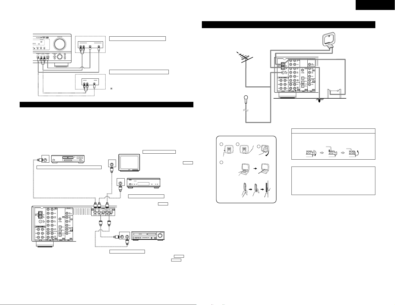
Connecting a Video game equipment
• Connect the Video game equipment’s output jacks
to this unit’s V. AUX INPUT lacks.
Connecting a Video camera equipment
• Connect the Video camera equipment’s output
jacks to this unit’s V. AUX INPUT lacks.
Video camera
Video game
The V. AUX terminal is covered with a cap.
Remove this cap in order to use the terminal. (See
page 3 for instructions on removing the cap.)
Connecting a video component equipped with S-Video jacks
• When making connections, also refer to the operating instructions of the other components.
• A note on the S input jacks
The input selectors for the S inputs and pin jack inputs work in conjunction with each other.
• Precaution when using S-jacks
This unit’s S-jacks (input and output) and video pin jacks (input and output) have independent circuit structures, so that video
signals input from the S-jacks are only output from the S-jack outputs and video signals input from the pin jacks are only output
from the pin jack outputs.
When connecting this unit with equipment that is equipped with S-jacks, keep the above point in mind and make connections
according to the equipment’s instruction manuals.
IN
S-VIDEO
OUT
S-VIDEO
OUT
S-VIDEO
OUT IN
S-VIDEO
VIDEO IN
VIDEO OUT
VIDEO IN
VIDEO OUT
VIDEO OUT
B
B
DVD player, VDP, etc.
Connecting a monitor TV
Monitor TV
Connecting a TV/DBS tuner
•
Connect the TV’s or DBS tuner’s S video output jack
(S-VIDEO OUTPUT) to the TV/DBS IN jack
using an S jack connection cord.
S-VIDEO
TV or satellite broadcast tuner
Video deck
Connecting the video decks
• Connect the video deck’s S output jack (S-OUT) to the VCR IN
jack and the video deck’s S input jack (S-IN) to the VCR OUT
jack using S jack connection cords.
S-VIDEO
S-VIDEO
Connecting a DVD player or video disc player (VDP)
DVD/VDP
• Connect the DVD player’s or video disc player’s SVideo output jack to the S-VIDEO DVD/VDP IN jack
using an S-Video connection cord.
MONITOR OUT
• Connect the TV’s or DBS tuner's S video
input (S-VIDEO INPUT) to the
MONITOR OUT jack using a S jack
connection cord.
S-VIDEO
Connecting the antenna terminals
DIRECTION OF
BROADCASTING
STATION
FM ANTENNA
75 Ω/ohms
COAXIAL
CABLE
FM INDOOR ANTENNA
(An Accessory)
AM LOOP
ANTENNA
(An Accessory)
AM OUTDOOR
ANTENNA
GROUND
NOTES:
•Do not connect two FM antennas simultaneously.
•Even if an external AM antenna is used, do not
disconnect the AM loop antenna.
•Make sure AM loop antenna lead terminals do
not touch metal parts of the panel.
Connection of AM antennas
1. Push the lever.
2. Insert the
conductor.
3. Return the lever.
AM loop antenna assembly
Connect to the AM
antenna terminals.
Bend in the reverse
direction.
Remove the vinyl tie
and take out the
connection line.
a. With the antenna
on top any stable
surface.
b. With the antenna
attached to a wall.
Installation hole Mount on wall, etc.
Mount
1
4
2
3
Page 8
ENGLISH
8
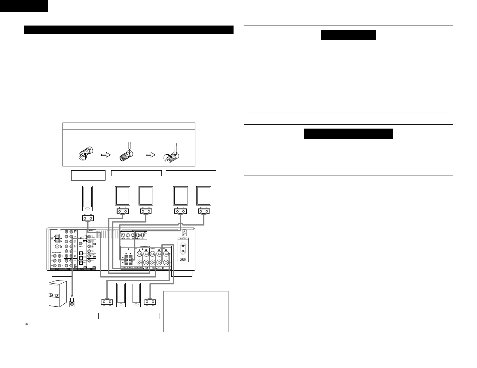
Speaker system connections
• Connect the speaker terminals with the speakers
making sure that like polarities are matched (< with
<, > with >). Mismatching of polarities will result
in weak central sound, unclear orientation of the
various instruments, and the sense of direction of the
stereo being impaired.
• When making connections, take care that none of
the individual conductors of the speaker cord come
in contact with adjacent terminals, with other speaker
cord conductors, or with the rear panel.
Speaker Impedance
• When speaker systems A and B are use separately,
speakers with an impedance of 6 to 16 Ω/ohms can
be connected for use as front speakers.
• Be careful when using two pairs of front speakers
(A + B) at the same time, since use of speakers with
an impedance of 12 to 16 Ω/ohms.
• Speakers with an impedance of 6 to 16 Ω/ohms can
be connected for use as center and surround speakers.
• The protector circuit may be activated if the set is
played for long periods of time at high volumes when
speakers with an impedance lower than the specified
impedance are connected.
1. Loosen by turning
counterclockwise.
2. Insert the cord.
3. Tighten by turning
clockwise.
NOTE:
NEVER touch the speaker terminals when the
power is on.
Doing so could result in electric shocks.
System B
FRONT SPEAKER SYSTEMS FRONT SPEAKER SYSTEMS
SURROUND SPEAKER SYSTEMS
• Precautions when connecting
speakers
If a speaker is placed near a TV or
video monitor, the colors on the
screen may be disturbed by the
speaker’s magnetism. If this should
happen, move the speaker away
to a position where it does not have
this effect.
Connection jack for subwoofer with
built-in amplifier (super woofer), etc.
To achieve Dolby Digital (AC-3)
playback effect, use a unit that can
sufficiently reproduce frequencies
of under 80 Hz.
Connecting the speaker cords
(L)(R)
(L) (R)(L) (R)
System A
CENTER SPEAKER
SYSTEM
Protector circuit
• This unit is equipped with a high-speed protection circuit. The purpose of this circuit is to protect the
speakers under circumstances such as when the output of the power amplifier is inadvertently shortcircuited and a large current flows, when the temperature surrounding the unit becomes unusually high,
or when the unit is used at high output over a long period which results in an extreme temperature rise.
When the protection circuit is activated, the speaker output is cut off and the power supply indicator
LED flashes. Should this occur, please follow these steps: be sure to switch off the power of this unit,
check whether there are any faults with the wiring of the speaker cables or input cables, and wait for
the unit to cool down if it is very hot. Improve the ventilation condition around the unit and switch the
power back on.
If the protection circuit is activated again even though there are no problems with the wiring or the
ventilation around the unit, switch off the power and contact a DENON service center.
Note on speaker impedance
• The protector circuit may be activated if the set is played for long periods of time at high volumes when
speakers with an impedance lower than the specified impedance (for example speakers with an impedance
of lower than 4 Ω/ohms) are connected. If the protector circuit is activated, the speaker output is cut off.
Turn off the set’s power, wait for the set to cool down, improve the ventilation around the set, then turn
the power back on.
Page 9
ENGLISH
9
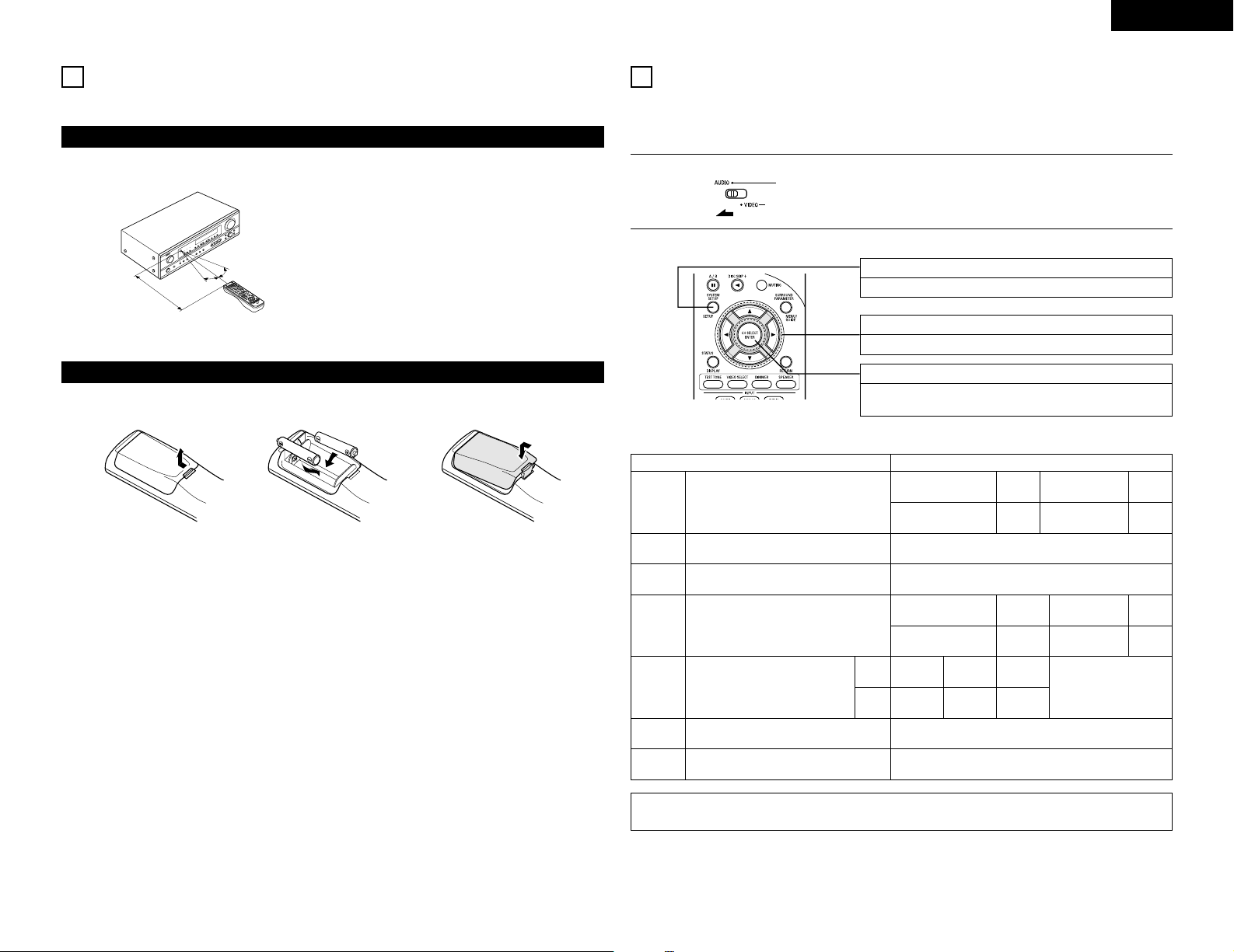
Following the procedure outlined below, insert the batteries before using the remote control unit.
Point the remote control unit at the remote control
sensor as shown on the diagram at the left.
NOTES:
• The remote control unit can be used from a straight
distance of approximately 7 meters, but this distance
will shorten or operation will become difficult if there
are obstacles between the remote control unit and
the remote control sensor, if the remote control
sensor is exposed to direct sunlight or other strong
light, or if operated from an angle.
• Neon signs or other devices emitting pulse-type noise
nearby may result in malfunction, so keep the set as
far away from such devices as possible.
Approx. 7 m
q Press as shown by the arrow
and slide off.
w Insert the R6P/AA batteries properly,
as shown on the diagram.
e Close the lid.
NOTES:
• Use only R6P/AA batteries for replacement.
• Be sure the polarities are correct. (See the illustration inside the battery compartment.)
• Remove the batteries if the remote control transmitter will not be used for an extended period of time.
• If batteries leak, dispose of them immediately. Avoid touching the leaked material or letting it come in contact
with clothing, etc. Clean the battery compartment thoroughly before installing new batteries.
• Have replacement batteries on hand so that the old batteries can be replaced as quickly as possible when the
time comes.
• Even if less than a year has passed, replace the batteries with new ones if the set does not operate even when
the remote control unit is operated nearby the set. (The included battery is only for verifying operation.
Replace it with a new battery as soon as possible.)
30°
9
USING THE REMOTE CONTROL UNIT
Range of operation of the remote control unit
Inserting the batteries
30°
10
SETTING UP THE SYSTEM
• Once all connections with other AV components have been completed as described in “CONNECTIONS” (see
pages 5 to 8), make the various settings described below on the display.
These settings are required to set up the listening room’s AV system centered around the this unit.
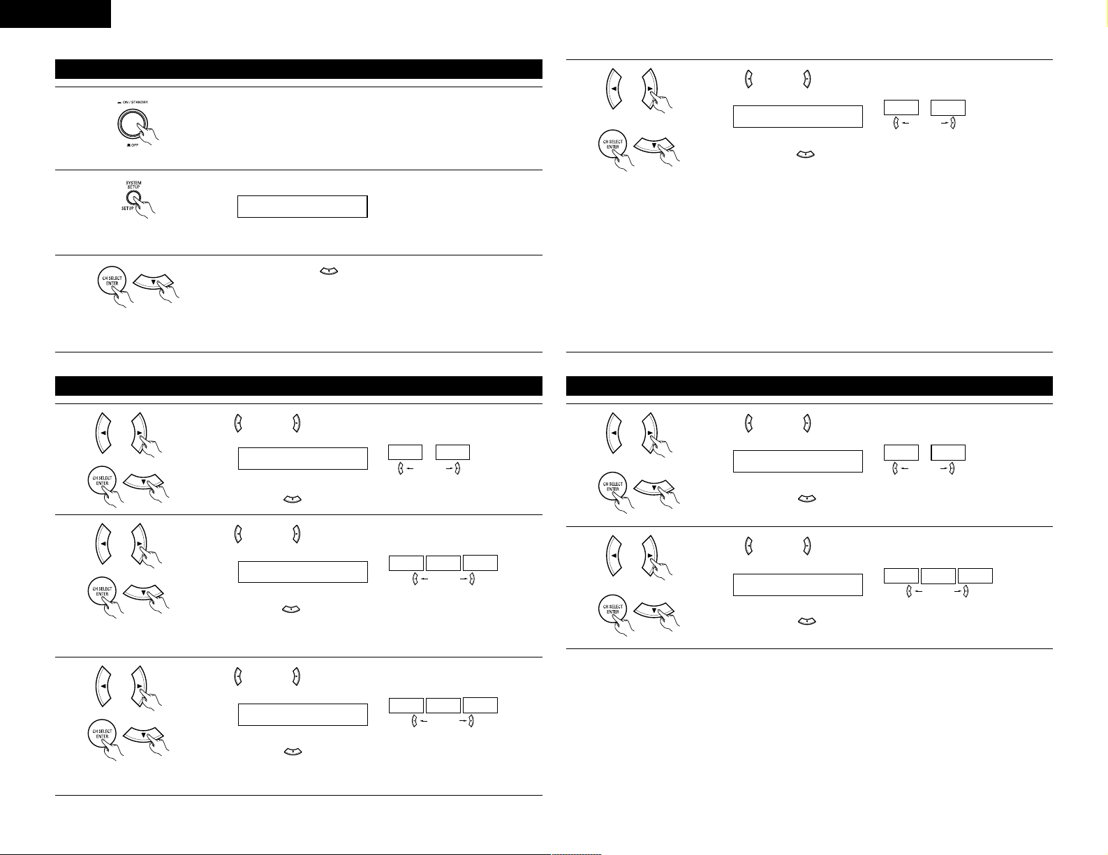
SYSTEM SETUP button
Press this to display the system setup on the display.
CURSOR buttons (•, ª, 0, 1)
Press this change what appears on the display.
ENTER button
Press this to switch the display.
Also use this button to complete the setting.
• System setup items and default values (set upon shipment from the factory)
Input the combination of speakers in your system and
their corresponding sizes (SMALL for regular speakers,
LARGE for full-size, full-range) to automatically set the
composition of the signals output from the speakers and
the frequency response.
Front Sp.
Center
Sp.
Surround Sp.
Subwoofer
Large Small Small Yes
System setup
Speaker
Configuration
This selects the subwoofer speaker for playing deep bass
signals.
This parameter is for optimizing the timing with which
the audio signals are produced from the speakers and
subwoofer according to the listening position.
Subwoofer
Mode
Delay Time
Default settings
Set the slide switch to “AUDIO”.
1
Use the following buttons to set up the system:
2
Subwoofer mode = Normal
Front & Subwoofer Center Surround L & R —
3.6 m 3.6 m 3.0 m —
NOTE:
• The system setup is not displayed when “HEADPHONE ONLY” is selected.
Digital
Inputs
Input
source
Digital In
Assignment
This assigns the digital input jacks for the
different input sources.
COAXIALCDOPTICAL-1 OPTICAL-2
DVD/VDP TV/DBS
Set the frequency (Hz) below which the bass sound of
the various speakers is to be output from the subwoofer.
Crossover
Frequency
80 Hz
Auto surround mode function setting.
Auto Surround
Mode
Auto Surround Mode = ON
Set the Ext. In Subwoofer channel playback level.
Ext. In SW
Level
Ext. In SW Level = +15 dB
Page 10
10
Check that all the components are correct, then press the POWER operation
switch on the main unit to turn on the power.
Press the SYSTEM SETUP button to enter the setting.
Press the ENTER or (down) button to switch to the speaker
configuration set up.
NOTE:
Press the SYSTEM SETUP button again to finish system set up. System set up can be finished at any time. The
changes to the settings made up to that point are entered.
1
2
3
*SYSTEM SET UP
Before setting up the system
NOTE: Please make sure the “AUDIO” position of the slide switch on the
remote control unit.
(Main unit)
Use the (left) and (right) buttons to select your center speaker type.
Press the ENTER or (down) button to switch to the surround speaker setting.
2 CENTER SMALL
LARGE
SMALL
NONE
NOTE:
• When “Small” has been selected for the front speakers, “Large” cannot be selected for the center speaker.
Use the (left) and (right) buttons to select your surround speaker type.
3
2
Press the ENTER or (down) button to switch to the subwoofer setting.
3 SURR. SMALL
LARGE
SMALL
NONE
NOTE:
• When “Small” has been selected for the front speakers, “Large” cannot be selected for the surround speakers.
Setting the speaker configuration
Use the (left) and (right) buttons to select your front speaker type.
Press the ENTER or (down) button to switch to the center speaker setting.
1 FRONT LARGE
LARGE
SMALL
(right) button(left) button
1
(right) button(left) button
(right) button(left) button
(Initial)
(Initial)
(Initial)
ENGLISH
Use the (left) and (right) buttons to select your subwoofer setting.
4
Press the ENTER or (down) button to enter the settings and switch to the
SUBWOOFER MODE setting.
4 S.WOOFER YES
YES
NO
• Parameters
Large…… Select this when using speakers that can fully reproduce low sounds of below 80 Hz.
Small…… Select this when using speakers that cannot reproduce low sounds of below 80 Hz with sufficient
volume. When this setting is selected, low frequencies of below 80 Hz are assigned to the subwoofer.
None…… Select this when no speakers are installed.
Yes/No…. Select “Yes” when a subwoofer is installed, “No” when it’s not installed.
NOTE:
Select “Large” or “Small” not according to the physical size of the speaker, but according to the bass reproduction
capacity at 80 Hz. If you cannot determine the best setting, try comparing the sound when set to “Small” and
when set to “Large”, at a level that will not damage the speakers.
Caution:
In case the subwoofer is not used, be sure to set “Subwoofer = No”, or the bass sound of front channel is divided
to subwoofer channel and not reproduced in some mode.
(right) button(left) button
(Initial)
Setting the Subwoofer mode and Crossover Frequency
Use the (left) and (right) buttons to select the Subwoofer mode.
Press the ENTER or (down) button to enter the setting and switch to the
Crossover Frequency setting.
5 SW MODE NORM
+MAIN NORM
(right) button(left) button
1
(Initial)
Use the (left) and (right) buttons to select the Crossover Frequency.
Press the ENTER or (down) button to enter the setting and switch to the
SPEAKER DISTANCE setting.
6 CR.OVER 80Hz
80Hz
100Hz
120Hz
(right) button(left) button
2
(Initial)
Page 11
ENGLISH
11
NOTES:
— Assignment of low frequency signal range —
• The only signals produced from the subwoofer channel are LFE signals (during playback of Dolby Digital or
DTS signals) and the low frequency signal range of channels set to “SMALL” in the setup menu. The low
frequency signal range of channels set to “LARGE” are produced from those channels.
— Crossover Frequency —
• When “Subwoofer“ is set to “Yes“ at the “Speaker Configuration Setting“, set the frequency (Hz) below
which the bass sound of the various speakers is to be output from the subwoofer (the crossover frequency).
• For speakers aet to “Small“, sound with a frequency below the crossover frequency is cut, and the cut bass
sound is output from the subwoofer instead.
NOTE: For ordinary speaker systems, we recommend setting the crossover frequency to 80 Hz. When
using small speakers, however, setting the crossover frequency to high frequency may improve
frequency response for frequencies near the crossover frequency.
— Subwoofer mode —
• The subwoofer mode setting is only valid when “LARGE” is set for the front speakers and “YES” is set for
the subwoofer in the “Speaker Configuration” settings (see page 10).
If “SMALL” is set for the front speakers or “NO” is set for the subwoofer, the subwoofer mode setting does
not affect playback of low frequency signal range.
• When the “+MAIN” playback mode is selected, the low frequency signal range of channels set to “LARGE”
are produced simultaneously from those channels and the subwoofer channel.
In this playback mode, the low frequency range expand more uniformly through the room, but depending on
the size and shape of the room, interference may result in a decrease of the actual volume of the low frequency
range.
• When the “NORM” playback mode is selected, the low frequency signal range of channels set to “LARGE”
are only produced from those channels. In this playback mode there tends to be little interference of the low
frequency range in the room.
• Try playing the music or movie source and select the playback mode providing the stronger low frequency
range sound.
Input the distances from the listening position to the speakers and set the surround
delay time.
Preparations:
Measure the distances from the listening position to the speakers (L
1 to L3 on the
diagram at the right).
L
1
: Distance from center speaker to listening position
L
2: Distance from front speakers to listening position
L
3: Distance from surround speakers to listening position
CAUTION:
Set the center speaker at the same distance from the front speakers (left and right) or the subwoofer, or so
that the difference in distance (L
2
– L1) is 1.5 meters or less.
Set the surround speakers (left and right) at the same distance from the front speakers (left and right) or the
subwoofer, or so that the difference in distance (L
2
– L3) is 4.5 meters or less.
• The number changes in units of 0.1 meter each time one of the buttons is
pressed. Select the value closest to the measured distance.
(“/SW” appears only when subwoofer = yes.)
Press the ENTER or (down) button to switch to the center speaker setting.
L1
L2
L3
7 FRNT/SW 3.6m
Listening
position
CenterFL FR
Setting the speaker distance
SL SR
Use the (left) and (right) buttons to set the distance from the front
speakers and subwoofer to the listening position.
1
NOTE:
• The speaker distance can be adjusted between 0 and 18 meters in steps of 0.1 meter.
Use the (left) and (right) buttons to set the distance from the center
speaker to the listening position.
2
Use the (left) and (right) buttons to set the distance from the surround
speakers to the listening position.
3
• The number changes in units of 0.1 meter each time one of the buttons is
pressed. Select the value closest to the measured distance.
Press the ENTER or (down) button to switch to the surround speakers
setting.
• The number changes in units of 0.1 meter each time one of the buttons is
pressed. Select the value closest to the measured distance.
Press the ENTER or (down) button to enter the setting and switch the
DIGITAL input (COAX) setting.
8 CENTER 3.6m
9 SURR. 3.0m
NOTE:
• No setting when “None” has been selected for the center speaker.
NOTE:
• No setting when “None” has been selected for the surround speakers.
Page 12
ENGLISH
12
NOTE:
• TUNER and V. AUX cannot be selected.
• Select “OFF” if nothing is connected.
12 OPT2 TV
CD AUX DVD TV VCR CDR OFF
Use the (left) and (right) buttons to assign the input function connected
to the OPTICAL input 2 (OPT 2) terminal.
3
(right) button(left) button
Press the ENTER or (down) button to switch the auto surround mode
setting.
(Initial)
13 AUTOSURR. ON
OFF ON
For the three kinds of input signals as shown below, the surround mode played the last is stored in the
memory. At next time it the same signal inputs, the memorized surround mode is automatically selected and
the signal is played.
Note that the surround mode setting is also stored separately for the different input function.
SIGNAL Default Auto Surround Mode
q Analog and PCM 2-channel signals STEREO
w 2-channel signals of Dolby Digital, DTS or other multichannel format Dolby PLII Cinema
e Multichannel signals of Dolby Digital, DTS or other multichannel format Dolby or DTS Surround
Setting the Auto Surround Mode
Use the (left) and (right) buttons to select the Auto Surround mode.
1
(right) button(left) button
Press the ENTER or (down) button to switch the Ext. In SW Level setting.
(Initial)
14 EXT.IN SW +15
+00
+05
+10 +15
Set the method of playback of the analog input signal connected to the Ext. In terminal.
Setting the Ext. In SW Level
Use the (left) and (right) buttons to select the Ext. In Subwoofer channel
Level playback.
1
(right) button(left) button
Press the ENTER or (down) button if you want to start the settings over
from the beginning.
(Initial)
This completes the system setup operations. Once the system is set up, there is no need to make the settings
again unless other components or speakers are connected to or the speaker layout is changed.
After setting up the system
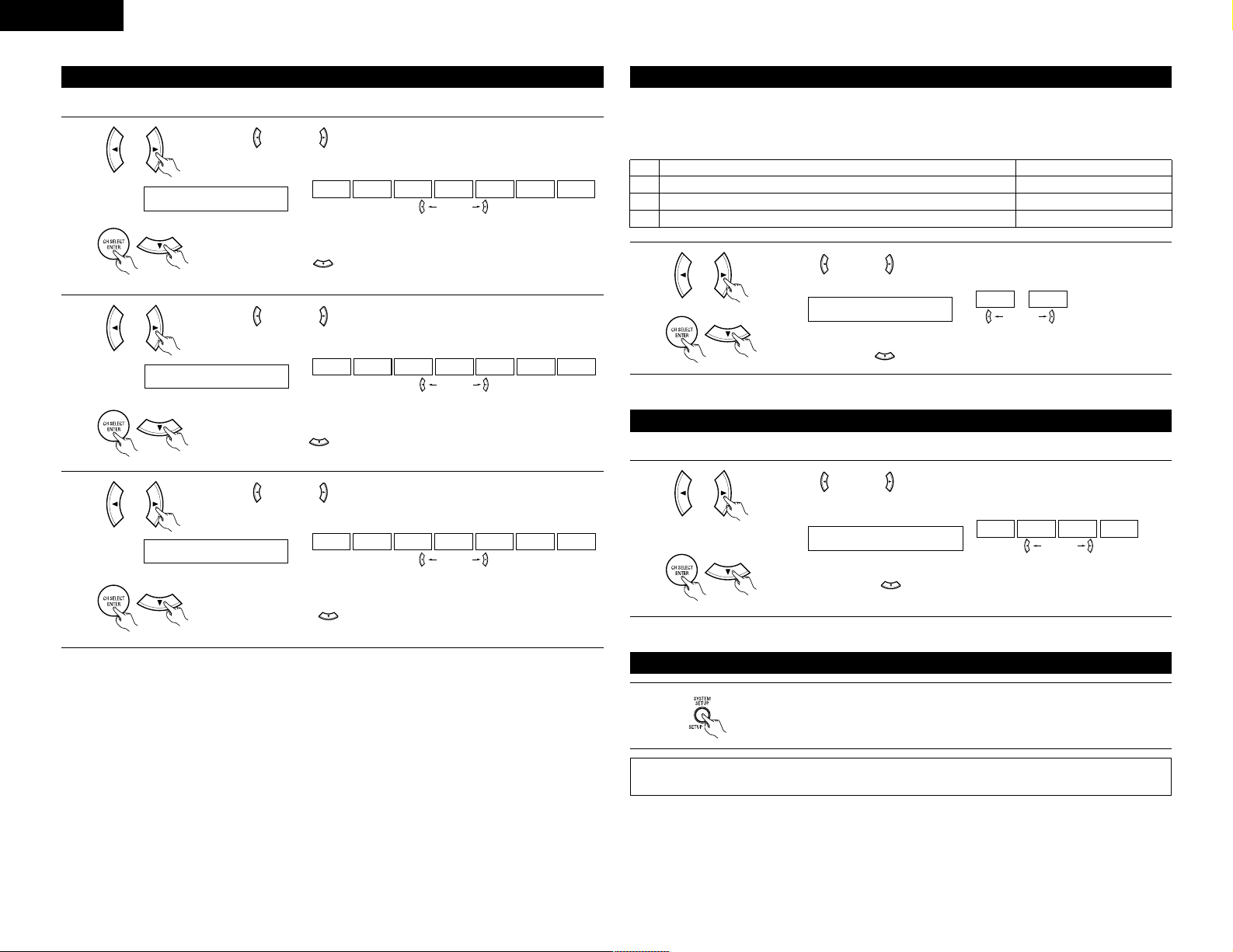
Press the SYSTEM SETUP button to finish system set up.
1
• Select “OFF” if nothing is connected.
Press the ENTER or (down) button to switch the OPTICAL input 2 (OPT 2)
setting.
10 COAX CD
CD AUX DVD TV VCR CDR OFF
11 OPT1 DVD
CD AUX DVD TV VCR CDR OFF
Input the type of components connected to the digital input terminals.
Setting the Digital In Assignment
Use the (left) and (right) buttons to assign the input function connected
to the COAXIAL input (COAXIAL) terminal.
1
Use the (left) and (right) buttons to assign the input function connected
to the OPTICAL input 1 (OPT 1) terminal.
2
(right) button(left) button
Press the ENTER or (down) button to switch the optical input 1 (OPT 1)
setting.
(right) button(left) button
• Select “OFF” if nothing is connected.
(Initial)
(Initial)
Page 13
13
ENGLISH
11
REMOTE CONTROL UNIT
• Turn on the power of the different components before operating them.
Set mode switch 1 to “AUDIO”.
1. CD player (CD) and CD recorder and MD
recorder (CDR/MD) system buttons
2. Tape deck (TAPE) system buttons
6,7 : Manual search
(reverse and forward)
2 : Stop
1 : Play
8,9 : Auto search (Cue)
3 : Pause
DISC : Switch discs
SKIP+ (for CD changers only)
6 : Rewind
7 : Fast-forward
2 : Stop
1 : Forward play
0 : Reverse play
A/B : Switch between decks A and B
3
2
1
3
3. Tuner system buttons
SHIFT : Switch preset channel range
CHANNEL : Preset channel
+, – (up/down)
TUNING : Frequency
+, – (up/down)
BAND : Switch between the AM and FM bands
MODE : Switch between auto and mono
MEMORY : Preset memory
NOTE:
• TUNER can be operated when the switch is at “AUDIO” position.
Operating DENON audio components
1
Set mode switch 2 to the position for the
component to be operated. (CD, CDR/MD or
Tape deck)
2
Operate the audio component.
• For details, refer to the component’s operating instructions.
While this remote control is compatible with a wide range of infrared controlled components, some
models of components may not be operated with this remote control.
3
DENON and other makes of components can be operated by setting the preset memory.
This remote control unit can be used to operate components of other manufacturers without using the learning
function by registering the manufacturer of the component as shown on the List of Preset Codes (pages
192~194).
Operation is not possible for some models.
Set mode switch 1 to “AUDIO” or “VIDEO”.
3
2
1
4
Preset memory
1
Set the AUDIO side for the CD, Tape deck or
CDR/MD position, to the VIDEO side for the
DVD/VDP, DBS/CABLE, VCR or TV position.
Set mode switch 2 to the component to be
registered.
2
Press the ON/SOURCE button and the OFF
button at the same time.
3
• Indicator flash.
Referring to the included List of Preset Codes, use the number buttons to input the
preset code (a 3-digit number) for the manufacturer of the component whose signals
you want to store in the memory.
4
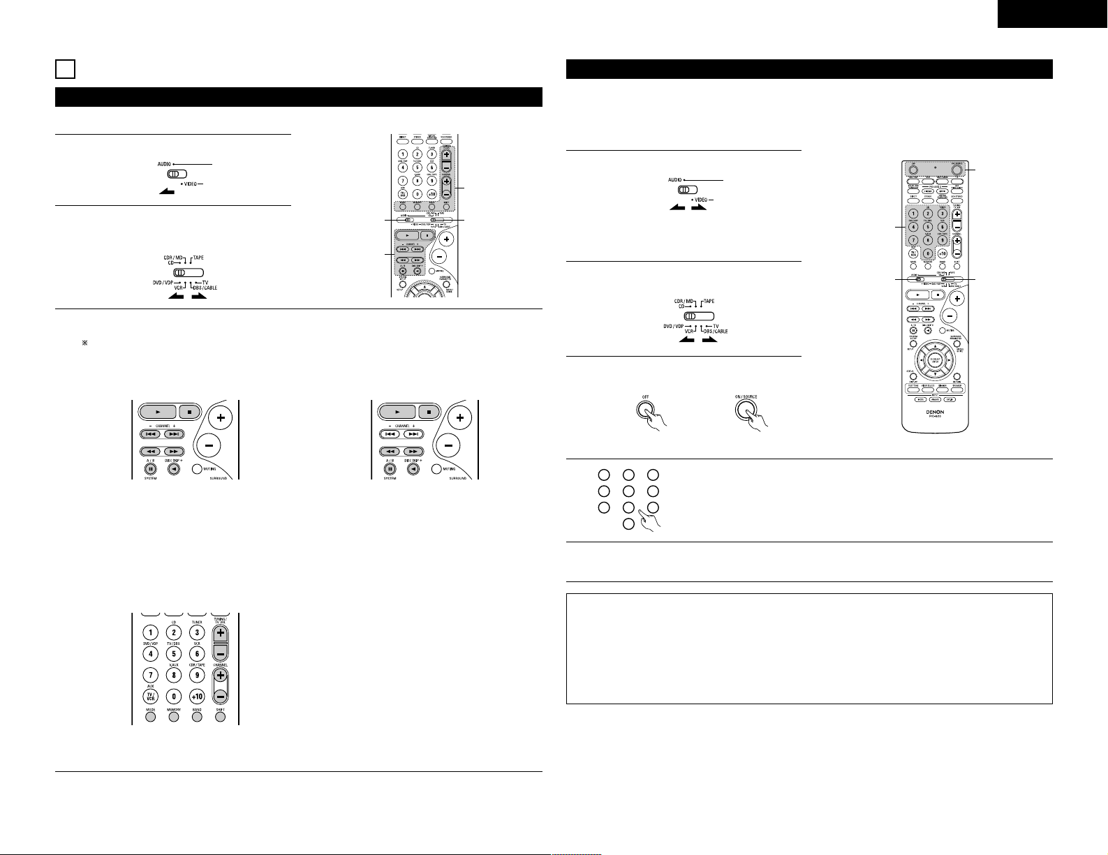
1
2
3
456
789
0
To store the codes of another component in the memory, repeat steps 1 to 4.
5
NOTES:
• The signals for the pressed buttons are emitted while setting the preset memory. To avoid accidental
operation, cover the remote control unit’s transmitting window while setting the preset memory.
• Depending on the model and year of manufacture, this function cannot be used for some models, even if
they are of makes listed on the included list of preset codes.
• Some manufacturers use more than one type of remote control code. Refer to the included list of preset
codes to change the number and check.
• The preset memory can be set for one component only among the following: CDR/MD, DVD/VDP
and DBS/CABLE.
The preset codes are as follows upon shipment from the factory and after resetting:
TV, VCR ..............................HITACHI
CD, TAPE ...........................DENON
CDR/MD.............................DENON (CDR)
DVD/VDP............................DENON (DVD)
DBS/CABLE........................ABC (CABLE)
Page 14
14
ENGLISH
NOTE:
• Some manufacturers use different names for
the DVD remote control buttons, so also
refer to the instructions on remote control for
that component.
Set mode switch 1 to “AUDIO” or “VIDEO”.
3
2
1
3
3
Operating component stored in the preset memory
1
Set mode switch 2 to the component you want
to operate.
2
Set the AUDIO side for the CD, Tape deck or
CDR/MD position, to the VIDEO side for the
DVD/VDP, DBS/CABLE, VCR or TV position.
1. Digital video disc player (DVD, DVD SETUP) system buttons
Operate the component.
• For details, refer to the component’s operating instructions.
Some models cannot be operated with this remote control unit.
3
POWER : Power on/standby
(ON/SOURCE)
6,7 : Manual search
(forward and reverse)
2 : Stop
1 : Play
8,9 : Auto search
(to beginning of track)
3 : Pause
0 ~ 9, +10 : 10 key
skip + : Disc skip
(for DVD changer only)
DISPLAY : Switch display
MENU : Menu
RETURN : Return
SETUP : Setup
D, H, F, G : Cursor up, down, left and right
ENTER : Enter setting
2. Video disc player (VDP) system buttons
POWER : Power on/standby
(ON/SOURCE)
6,7 : Manual search
(forward and
reverse)
2 : Stop
1 : Play
8,9: Auto search (cue)
3 : Pause
0~9, +10 : 10 key
3. Video deck (VCR) system buttons
POWER : Power on/standby
(ON/SOURCE)
6,7 : Manual search
(forward and
reverse)
2 : Stop
1 :Play
3 : Pause
Channel +, –: Channels
4. Digital broadcast satellite (DBS) tuner and
cable (CABLE) system buttons
POWER : Power on/standby
(ON/SOURCE)
MENU : Menu
RETURN : Return
D, H, F, G : Cursor up, down,
left and right
ENTER : Enter
CHANNEL : Switch channels
+, –
0~9, +10 : Channels
DISPLAY : Switch display
VOL +, – : Volume up/down
5. Monitor TV (TV) system buttons
POWER : Power on/standby
(ON/SOURCE)
MENU : Menu
RETURN : Return
D, H, F, G : Cursor up, down,
left and right
ENTER : Enter
CHANNEL : Switch channels
+, –
0~9, +10 : Channels
DISPLAY : Switch display
TV/VCR : Switch between
TV and video
player
TV VOL : Volume up/down
+, –
NOTES:
• For this CD, CDR, MD and TAPE components, buttons can be operated in the same way as for Denon
audio components (page 13).
• The TV can be operated when the switch is at DVD/VDP, VCR, TV position.
Page 15
15
Punch Through
ENGLISH
Preparations:
Check that all connections are proper.
Turn on the power.
Press the power operation switch (button).
12
OPERATION
Before operating
1
Select the front speakers.
Press the SPEAKER A or B button turn the speaker
on.
2
• ¢ ON/STANDBY
The power turns on and power indicator is lit.
Several seconds are required from the time
the power operation switch is set to the “¢
ON/STANDBY” position until sound is output.
This is due to the built-in muting circuit that
prevents noise when the power switch is turned
on and off.
Set the power operation switch to this position
to turn the power on and off from the included
remote control unit.
• £ OFF
The power turns off and power indicator is off.
In this position, the power cannot be turned on
and off from the remote control unit.
(Main unit) (Remote control unit)
(Main unit)
•“Punch Through” is a function allowing you to operate the PLAY, STOP, MANUAL SEARCH and AUTO
SEARCH buttons on the CD, TAPE, CDR/MD, DVD/VDP or VCR components when in the DBS/CABLE or TV
mode. By default, nothing is set.
Set mode switch 1 to “VIDEO”.
3
2
1
4
3
1
Set mode switch 2 to the component to be
registered (DBS/CABLE or TV).
2
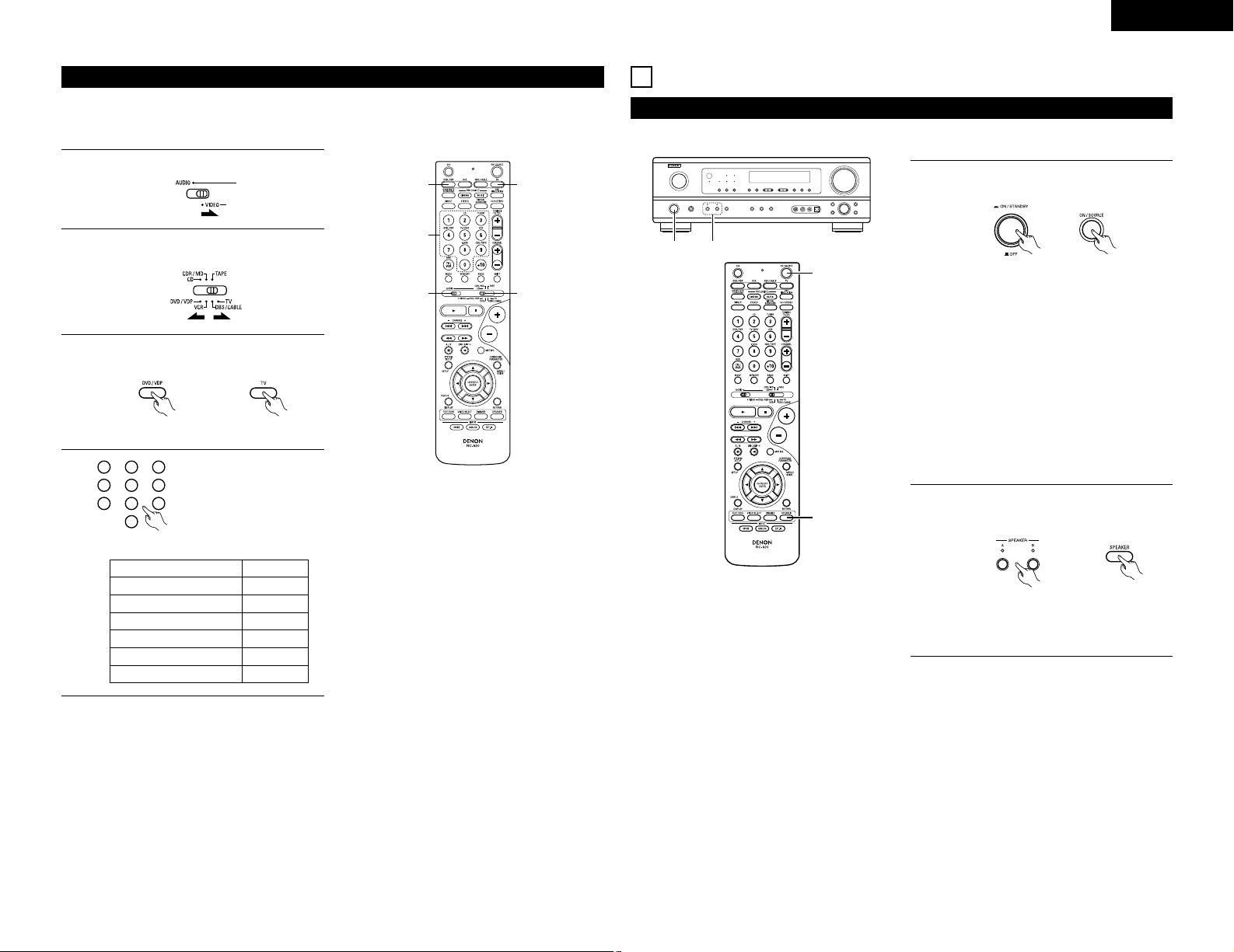
Press the DVD/VDP power button and the TV
power button at the same time.
3
• Indicator flash.
Input the number of the
component you want to set.
(See Table 1)
4
1
2
3
456
789
0
Table 1
CD 1
TAPE 2
CDR/MD 3
DVD/VDP 4
VCR 5
No setting 0
No.
(Remote control unit)
• The front speaker A, B setting can be also be
changed with the SPEAKER button on the
remote control unit.
1 2
1
2
Page 16
ENGLISH
16
Playing the input source
3
1 2 5
5
1
3
2
Select the input source to be played.
Example: CD
1
(Main unit) (Remote control unit)
Select the input mode.
• Selecting the analog mode
Press the ANALOG button to switch to the
analog input.
2
(Main unit) (Remote control unit)
• Selecting the external input (EXT. IN) mode
Press the EXT. IN (or the EXT. IN button on
the remote control unit) to switch the external
input.
(Main unit) (Remote control unit)
• Selecting the AUTO, PCM and DTS modes
The mode switches as shown below each time
the INPUT MODE button is pressed.
AUTO PCM DTS
(Main unit) (Remote control unit)
Input mode selection function
Different input modes can be selected for the different
input sources. The selected input modes for the
separate input sources are stored in the memory.
q AUTO (All auto mode)
In this mode, the types of signals being input to the
digital and analog input jacks for the selected input
source are detected and the program in the AVR1603’s surround decoder is selected automatically
Notes on playing a source encoded with DTS
• Noise may be generated at the beginning of
playback and while searching during DTS
playback in the AUTO mode. If so, play in the
DTS mode.
•
In some rare cases the noise may be generated
when you preform the operation to stop
playback of a DTS-CD or DTS-LD.
upon playback. This mode can be selected for all
input sources other than TUNER.
The presence or absence of digital signals is
detected, the signals input to the digital input jacks
are identified and decoding and playback are
performed automatically in DTS, Dolby Digital or
PCM (2 channel stereo) format. If no digital signal
is being input, the analog input jacks are selected.
Use this mode to play Dolby Digital signals.
w PCM (exclusive PCM signal playback mode)
Decoding and playback are only performed when
PCM signals are being input.
Note that noise may be generated when using this
mode to play signals other than PCM signals.
e DTS (exclusive DTS signal playback mode)
Decoding and playback are only performed when
DTS signals are being input.
r ANALOG (exclusive analog audio signal playback
mode)
The signals input to the analog input jacks are
decoded and played.
t EXT. IN (external decoder input jack selection mode)
The signals being input to the external decoder
input jacks are played without passing through the
surround circuitry.
NOTE:
• Note that noise will be output when CDs or LDs
recorded in DTS format are played in the “PCM”
(exclusive PCM signal playback) or “ANALOG”
(exclusive analog audio signal playback) mode.
Select the AUTO or DTS (exclusive DTS signal
playback) mode when playing signals recorded in
DTS from a laser disc player.
Select the play mode.
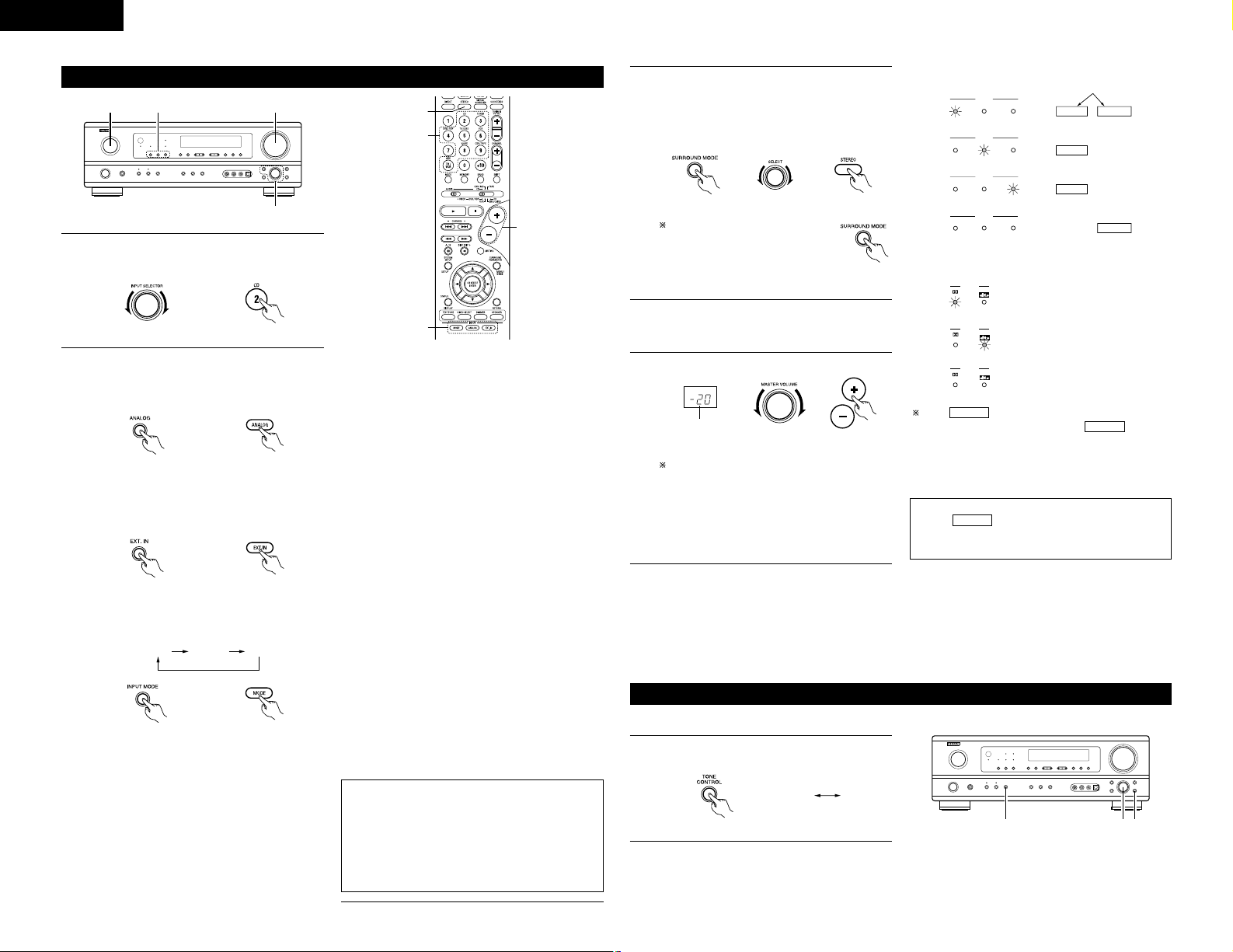
Press the SURROUND MODE button, then turn
the SELECT knob.
Example: Stereo
3
(Main unit) (Remote control unit)
To select the surround mode
while adjusting the surround
parameters, channel volume or
tone control, press the surround
mode button then operate the
selector. (See page 18.)
(Main unit)
Start playback on the selected component.
•
For operating instructions, refer to the component’s
manual.
4
Adjust the volume.
5
(Main unit) (Remote control unit)
The volume level is
displayed on the master
volume level display.
The volume can be adjusted within the range
of –70 to 0 to 18 dB, in steps of 1 dB. However,
when the channel level is set as described on
page 18, if the volume for any channel is set
at +1 dB or greater, the volume cannot be
adjusted up to 18 dB. (In this case the
maximum volume is adjusted to “18 dB —
(Maximum value of channel level)”.)
Input mode when playing DTS sources
• Noise will be output if DTS-compatible CDs or LDs
are played in the “ANALOG” or “PCM” mode.
When playing DTS-compatible sources, be sure to
connect the source component to the digital input
jacks (OPTICAL/COAXIAL) and set the input mode
to “DTS”.
Input mode display
ANALOGDIGITAL
DIGITAL
DIGITAL
ANALOG
AUTO
PCM
DTS
INPUT
AUTO
PCM
DTS
INPUT
AUTO
PCM
DTS
INPUT
AUTO
PCM
DTS
INPUT
• In the AUTO mode
• In the DIGITAL PCM mode
• In the DIGITAL DTS mode
• In the ANALOG mode
One of these lights, depending
on the input signal.
Input signal display
SIGNAL
DIGITAL
DIGITAL
DIGITAL
SIGNAL
SIGNAL
• DOLBY DIGITAL
• DTS
• PCM
The indicator lights when digital signals
are being input properly. If the indicator
does not light, check whether the digital input
component setup (page 12) and connections are
correct and whether the component’s power is
turned on.
DIGITAL
DIGITAL
NOTE:
• The indicator will light when playing
CD-ROMs containing data other than audio signals,
but no sound will be heard.
DIGITAL
After starting playback
[1] Adjusting the sound quality (tone)
1
The tone switches as follows each time the TONE
CONTROL button is pressed.
BASS TREBLE
123
(Main unit)
Page 17
Front panel display
• Descriptions of the unit’s operations
are also displayed on the front panel
display. In addition, the display can
be switched to check the unit’s
operating status while playing a
source by pressing the STATUS
button.
ENGLISH
17
2
With the name of the volume to
be adjusted selected, turn the
SELECT knob to adjust the level.
• To increase the bass or treble:
Turn the control clockwise.
(The bass or treble sound can
be increased to up to +12 dB in steps of 2 dB.)
•
To decrease the bass or treble: Turn the
control counterclockwise. (The bass or
treble sound
can be decreased to up to –12
dB in steps of 2 dB.)
3
If you do not want the bass and treble to be
adjusted, turn on the tone defeat mode.
The signals do not pass through the
bass and treble adjustment circuits,
providing higher quality sound.
(Main unit)
(Main unit)
[2] Listening over headphones
NOTE:
To prevent hearing loss, do not raise the volume level
excessively when using headphones.
1
Plug the headphones’ plug into
the jack.
Connect the headphones to
the PHONES jack.
The pre-out output (including
the speaker output) is
automatically turned off
when headphones are
connected.
1
PHONES
[3] Turning the sound off temporarily (muting)
1
Use this to turn off the audio output
temporarily.
Press the MUTING button.
Cancelling MUTING mode.
Press the MUTING button again.
Muting will also be cancelled
when MASTER VOL is adjusted
up or down.
(Remote
control unit)
Simulcast playback
Use this switch to monitor a video
source other than the audio source.
Press the VIDEO SELECT button
repeatedly until the desired source
appears on the display.
Cancelling simulcast playback.
• Select “SOURCE” using the VIDEO SELECT
button.
• Switch the program source to the component
connected to the video input jacks.
[4]
Combining the currently playing sound with the desired image
1
(Remote
control unit)
[5] Checking the currently playing program source, etc.
1
(Remote
control unit)
Using the dimmer function
• Use this to change the brightness of
the display.
The display brightness changes in
four steps (bright, medium, dim and
off) by pressing the main unit’s
DIMMER button repeatedly.
2
(Remote
control unit)
BRIGHT MEDIUM
OFF
DIM
Playback using the external input (EXT. IN) jacks
Set the external input (EXT. IN) mode.
Press the EXT. IN button
to switch the external
input.
Once this is selected,
the input signals
connected to the FL (front left), FR (front right),
C (center), SL (surround left) and SR (surround
right) channels of the EXT. IN jacks are output
directly to the front (left and right), center,
surround (left and right) speaker systems
without passing through the surround circuitry.
In addition, the signal input to the SW (subwoofer)
jack is output to the PRE OUT SUBWOOFER jack.
1
2
Cancelling the external input mode
To cancel the external input (EXT. IN) setting,
press the INPUT MODE (AUTO, PCM, DTS) or
ANALOG button to switch to the desired input
mode. (See page 16.)
(Remote control unit)(Main unit)
• When the input mode is set to the external input
(EXT. IN), the play mode (DIRECT,STEREO,
DOLBY/DTS SURROUND, 5CH STEREO or DSP
SIMULATION) cannot be selected.
2 1
NOTES:
• In play modes other than the external input mode,
the signals connected to EXT. IN jacks cannot
be played. In addition, signals cannot be output
from channels not connected to the input jacks.
• The external input mode can be set for any input
source. To watch video while listening to sound,
select the input source to which the video signal
is connected, then set this mode.
(Remote
control unit)
(Main unit)
1
1
1
2
21
Page 18
18
ENGLISH
Recording the program source (recording the source currently being monitored)
1
Follow step 1 to 3 under “Playing the input source”.
2
Start recording on the tape or video deck.
For instructions, refer to the component’s operating
instructions.
The signals of the source selected with the function selector button are output simultaneously to the
CDR/TAPE and VCR AUDIO OUT jacks. If a total of two tape and/or video decks are connected and set to
the recording mode, the same source can be recorded simultaneously on every decks.
Simultaneous recording
NOTES:
• The AUDIO IN’s signal selected with the function selector button are output to the CDR/TAPE and VCR
AUDIO OUT jacks.
• The DIGITAL IN’s signal selected with the function selector button are output to the DIGITAL OUT (OPTICAL)
jack.
13
SURROUND
Before playing with the surround function
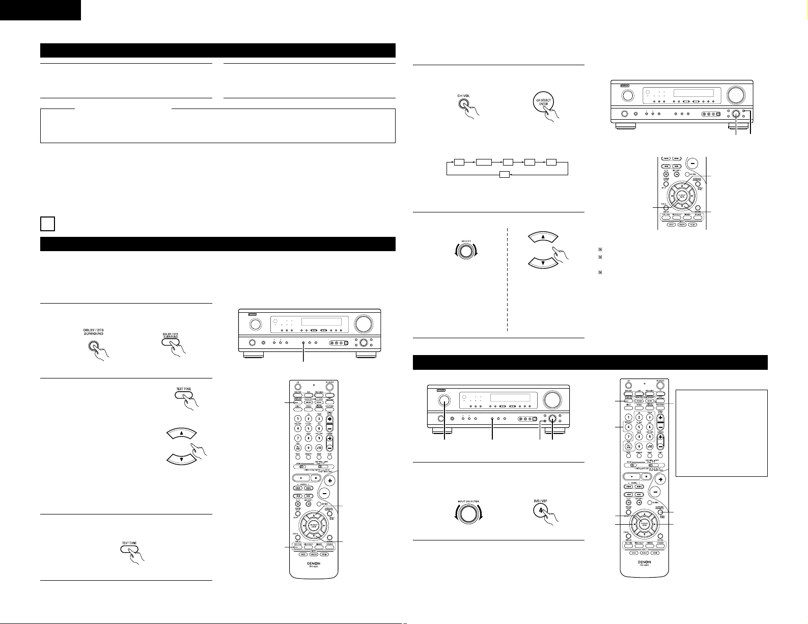
• Before playing with the surround function, be sure to use the test tones to adjust the playback level from each
speakers. This adjustment can be performed from the remote control unit, as (described) below.
• The adjustment with the test tones is only effective in the DOLBY/DTS SURROUND modes.
The adjusted playback levels for the different surround modes are automatically stored in the memory of each
surround modes.
1
Set the DOLBY/DTS SURROUND (Dolby Pro
Logic II or Dolby Digital or DTS) modes.
(Main unit) (Remote control unit)
2
Press the TEST TONE button.
(Remote control unit)
Test tones are output from the
different speakers. Use the
channel volume adjust buttons
to adjust so that the volume of
the test tones is the same for
all the speakers.
NOTE: Please make sure the “AUDIO” position
of the slide switch on the remote control
unit.
(Remote control unit)
3
After completing the adjustment, press the
TEST TONE button again.
1
2
2
2, 3
1
(Remote control unit)
• After adjusting using the test tones, adjust the channel levels either according to the playback sources or to
suit your tastes, as (described) below.
1
Select the speaker whose level you want to
adjust.
The channel switches as shown below each time
the button is pressed.
FL CNTR FR SR SL
SW
(Main unit) (Remote control unit)
NOTE: Please make sure the “AUDIO” position
of the slide switch on the remote control
unit.
2
Adjust the level of the selected speaker.
(Main unit) (Remote control unit)
2 1
2
2
1
Default setting of channel level is 0 dB.
The level of the selected speaker can be adjusted
within the range of +12 to –12 dB.
SW channel level can be turned off by decreasing
one step from -12 dB.
OFF ´ -12 dB ´ 12 dB
Only adjustable when
the channel is
selected with the CH
VOL buttons on the
main unit.
Dolby Surround Pro Logic IImode
1
Select the function to which the component you
want to play is connected.
5, 74, 61 2
4, 6
5, 7
1
8
5, 7
2
(Main unit) (Remote control unit)
Example:
The Dolby Surround Pro
Logic II Cinema or Music
mode can be chosen
directly by pressing the
CINEMA or MUSIC
button on the remote
control unit during
playback in the Dolby
Surround Pro Logic II
mode.
Page 19

19
ENGLISH
Light
3
Play a program source with the
mark.
• For operating instructions, refer to the manuals
of the respective components.
2
Select the Dolby Surround Pro Logic II mode.
(Main unit) (Remote control unit)
• The Dolby Pro Logic indicator lights.
Display
4
Select the surround parameter mode.
(Main unit) (Remote control unit)
Display
MODE cinema
To perform this operation from the remote
control unit, check that the mode selector
switch is set to “AUDIO”.
5
Select the optimum mode for the source.
(Main unit) (Remote control unit)
or or
MODE musicMODE cinemaMODE emulation
6
Set the surround parameters according to the
mode.
(Main unit) (Remote control unit)
• The mode switches as shown below each
time the button is pressed.
MODE EMULATION
CINEMA EQ
DEFAULT
MODE CINEMA
CINEMA EQ
DEFAULT
MODE MUSIC
PANORAMA
DIMENSION
CENTER WIDTH
DEFAULT
7
Set the various surround parameters.
OFF ON
or or
CINEMA EQ OFF
• CINEMA EQ setting
OFF ON
or or
PANORAMA OFF
• PANORAMA setting
0 3 6
or or
DIMENSION 3
• DIMENSION setting
0
CENTER WIDTH O
4 7
or or
• CENTER WIDTH setting
YES Y/N NO
or or
DEFAULT Y/N
• DEFAULT setting
Select “Yes” to reset to the factory defaults.
NOTE:
• When making parameter settings, the display will
return to the regular condition several seconds
after the last button was pressed and the setting
will be completed.
Surround parameters q
Pro Logic
II Mode:
The Cinema mode is for use with stereo television shows and all programs encoded in Dolby Surround.
The Music mode is recommended as the standard mode for autosound music systems (no video), and is
optional for A/V systems.
The Emulation mode offers the same robust surround processing as original Pro Logic in case the source
contents is not of optimum quality.
Select one of the modes (“Cinema”, “Music” or “Emulation”).
Panorama Control:
This mode extends the front stereo image to include the surround speakers for an exciting “wraparound”
effect with side wall imaging.
Select “OFF” or “ON”.
Dimension Control:
This control gradually adjust the soundfield either towards the front or towards the rear.
The control can be set in 7 steps from 0 to 6.
Center Width Control:
This control adjust the center image so it may be heard only from the center speaker; only from the left/right
speakers as a phontom image; or from all three front speakers to varying degrees.
The control can be set in 8 steps from 0 to 7.
Dolby Digital mode (only with digital input) and DTS Surround (only with digital input)
1
Select the input source.
(Main unit) (Remote control unit)
q Select an input source set to digital (COAXIAL/
OPTICAL) (see page 12).
Playback with a digital input
Example:
(Main unit) (Remote control unit)
w Set the input mode to “AUTO” or “DTS”.
2
Select the Dolby/DTS Surround mode.
(Main unit) (Remote control unit)
4, 5, 6, 7, 8
5, 6, 7, 8
5, 6, 7, 8
5, 6, 7, 8
1
1
9
2
3
Play a program source with the ,
mark.
• The Dolby Digital indicator
lights when playing Dolby
Digital sources.
DIGITAL
Light
• The DTS indicator lights when
playing DTS sources.
Light
8
Press the ENTER button to finish surround
parameter mode.
(Remote control unit)
1 1 3
2
Page 20

20
ENGLISH
Set the surround parameter according to the source.
First, press the SURROUND PARAMETER button.
4
(Remote control unit)
NOTE: Please make sure the “AUDIO” position of the slide switch on the remote
control unit.
5
Use the (left) and (right) buttons to set the CINEMA EQ.
CINEMA EQ OFF
OFF
ON
Press the SURROUND PARAMETER or (down) button to switch to the D.
COMP. setting.
NOTE: This parameter is not displayed during DTS playback.
(Remote control unit)
(Remote control unit)
(right) button(left) button
(Initial)
6
Use the (left) and (right) buttons to set the D. COMP.
D.COMP. OFF
OFF LOW MID HI
Press the SURROUND PARAMETER or (down) button to switch to the
LFE setting.
(Remote control unit)
(Remote control unit)
(right) button(left) button
(Initial)
7
Use the (left) and (right) buttons to set the LFE level.
LFE 0dB
• The level can be adjusted in units of 1 dB from –10 to 0 dB.
Set to the desired level according to the speaker systems being used and the
source to be played.
Press the SURROUND PARAMETER or (down) button to switch to the
default setting.
(Remote control unit)
(Remote control unit)
8
To reset the settings to the factory defaults, use the (left) and (right) to
display “Yes”.
DEFAULT Y/N
YES
Y/N NO
Press the SURROUND PARAMETER or (down) button to switch to the
CINEMA EQ. setting.
(Remote control unit)
(Remote control unit)
(right) button(left) button
Surround parameters w
CINEMA EQ. (Cinema Equalizer):
The Cinema EQ function gently decreases the level of the extreme high frequencies, compensating for
overly-bright sounding motion picture soundtracks. Select this function if the sound from the front speakers
is too bright.
This function only works in the Dolby Pro Logic, Dolby Digital and DTS Surround modes.
D.COMP. (Dynamic Range Compression):
Motion picture soundtracks have tremendous dynamic range (the contrast between very soft and very loud
sounds). For listening late at night, or whenever the maximum sound level is lower than usual, the Dynamic
Range Compression allows you to hear all of the sounds in the soundtrack (but with reduced dynamic range).
(This only works when playing program sources recorded in Dolby Digital.) Select one of the four parameters
(“OFF”, “LOW”, “MID” (middle) or “HI” (high)). Set to OFF for normal listening.
LFE (Low Frequency Effect):
Program source and adjustment range
1. Dolby Digital: –10 dB to 0 dB
2. DTS Surround: –10 dB to 0 dB
When Dolby Digital encoded software is played, it is recommended that the LFE LEVEL be set to
0 dB for correct Dolby Digital playback.
When DTS encoded movie software is played, it is recommended that the LFE LEVEL be set to
0 dB for correct DTS playback.
When DTS encoded music software is played, it is recommended that the LFE LEVEL be set to
-10 dB for correct DTS playback.
9
Press the ENTER button to finish surround parameter mode.
(Remote control unit)
Page 21

21
ENGLISH
14
DSP SURROUND SIMULATION
• This unit is equipped with a high performance DSP (Digital Signal Processor) which uses digital signal processing
to synthetically recreate the sound field. One of 7 preset surround modes can be selected according to the
program source and the parameters can be adjusted according to the conditions in the listening room to achieve
a more realistic, powerful sound. These surround modes can also be used for program sources not recorded in
Dolby Surround Pro Logic or Dolby Digital.
Surround modes and their features
1
2
3
4
5
6
7 VIRTUAL
ROCK ARENA
JAZZ CLUB
VIDEO GAME
MONO MOVIE
(NOTE 1)
MATRIX
5CH STEREO
Select this mode to enjoy a virtual sound field, produced from the front 2-channel
speakers.
Use this mode to achieve the feeling of a live concert in an arena with reflected
sounds coming from all directions.
This mode creates the sound field of a live house with a low ceiling and hard walls.
This mode gives jazz a very vivid realism.
Use this to enjoy video game sources.
Select this when watching monaural movies for a greater sense of expansion.
Select this to emphasize the sense of expansion for music sources recorded in stereo.
Signals consisting of the difference component of the input signals (the component
that provides the sense of expansion) processed for delay are output from the surround
channel.
In this mode, the signals of the front left channel are output from the left surround
channel, the signals of the front right channel are output from the right surround
channel, and the same (in-phase) component of the left and right channels is output
from the center channel. This mode provides all speaker surround sound, but without
directional steering effects, and works with any stereo program source.
Depending on the program source being played, the effect may not be very noticeable.
In this case, try other surround modes, without worrying about their names, to create a sound field suited to
your tastes.
NOTE 1: When playing sources recorded in monaural, the sound will be one-sided if signals are only input to one
channel (left or right), so input signals to both channels. If you have a source component with only one
audio output (monophonic camcorder, etc.) obtain a “Y” adaptor cable to split the mono output to two
outputs, and connect to the L and R inputs.
NOTE:
DIRECT, STEREO and 5CH STEREO mode can be used when playing PCM signals with a sampling
frequency of 96 kHz (such as from DVD-Video discs that contain 24 bit, 96 kHz audio). If such signals are
input during playback in one of the other surround modes, the mode automatically switches to STEREO.
Personal Memory Plus
This set is equipped with a personal memorize function that automatically memorizes the surround modes
and input modes selected for the input different sources. When the input source is switched, the modes
set for that source last time it was used are automatically recalled.
The surround parameters, tone control settings and playback level balance for the different output
channels are memorized for each surround mode.
DSP surround simulation
• To operate the surround mode and surround parameters from the remote control unit.
1
Select the surround mode for the input channel.
(Remote control unit)
The surround mode switches in the following
order each time the DSP SIMULATION button is
pressed:
MONO MOVIE ROCK ARENA
JAZZ CLUBVIDEO GAME
MATRIX
2
33
4
1
2
To enter the surround parameter setting mode, press the SURROUND
PARAMETER button.
• The surround parameter switches in the following order each time the
SURROUND PARAMETER button is pressed for the different surround
modes.
(Remote control unit)
ROOM SIZE
EFFECT
DEFAULT
DELAY
DEFAULT
D. COMP.
LFE
DEFAULT
• ROCK ARENA
• JAZZ CLUB
• VIDEO GAME
• MONO MOVIE
• MATRIX • VIRTUAL
Use the (left) and (right) buttons to set the room size.
ROOM SIZE MED
LARGEMED-LMEDMED-SSMALL
(Remote control unit)
(right) button(left) button
Use the (left) and (right) buttons to set the effect level.
EFFECT LEVEL 10
15101
(Remote control unit)
(right) button(left) button
3
Display the parameter you want to adjust, then use the (left) and (right)
buttons to set it.
(1) ROOM SIZE
(Initial)
(2) EFFECT LEVEL
(Initial)
Page 22

22
ENGLISH
Use the (left) and (right) buttons to set the delay time.
DELAY 30ms
110ms30ms0ms
(Remote control unit)
(right) button(left) button
(3) DELAY TIME
(Initial)
Use the (left) and (right) buttons to set the D. COMP.
D.COMP. OFF
OFF LOW MID HI
(Remote control unit)
(right) button(left) button
(4) D. COMP.
(Initial)
Use the (left) and (right) buttons to set the LFE level.
LFE 0dB
-10dB
0dB
(Remote control unit)
(right) button(left) button
(5) LFE
(Initial)
NOTE: This parameter is displayed during DOLBY DIGITAL playback.
NOTE: This parameter is displayed during DOLBY DIGITAL and DTS playback.
To reset the settings to the factory defaults, use the (left) and (right)
buttons to display “Yes”.
DEFAULT Y/N
NOY/NYES
(Remote control unit)
(right) button(left) button
(6) DEFAULT
• Operating the surround mode and surround parameters from the main unit‘s panel.
1
Turn the SELECT knob to select the surround
mode.
(Main unit)
• When turned clockwise
DIRECT STEREO DOLBY PRO LOGIC II
5CH STEREO
MONO MOVIE
JAZZ CLUB ROCK ARENAVIDEO GAMEMATRIXVIRTUAL SURROUND
DIRECT STEREO DOLBY PRO LOGIC II
5CH STEREO
MONO MOVIE
JAZZ CLUB ROCK ARENAVIDEO GAMEMATRIXVIRTUAL SURROUND
• When turned counterclockwise
To select the surround mode while adjusting the surround parameters, channel volume or tone control,
press the SURROUND MODE button then operate the selector.
(Main unit)
1, 321
2
Press the SURROUND PARAMETER button.
Press and hold in the surround parameter button to select the parameter you want to set.
• The parameters which can be set differ for the different surround modes. (Refer to “Surround Modes and
Parameters” on page 23.)
(Main unit)
3
Display the parameter you want to adjust, then turn the SELECT knob to set it.
NOTE:
• When playing PCM digital signals or analog signals in the 5CH STEREO, ROCK ARENA, JAZZ CLUB, VIDEO
GAME, MONO MOVIE or MATRIX surround modes and the input signal switches to a digital signal encoded
in Dolby Digital, the Dolby surround mode switches automatically. When the input signal switches to a DTS
signal, the mode automatically switches to DTS surround.
Surround parameters e
ROOM SIZE:
This sets the size of the sound field.
There are five settings: “small”, “med.s” (medium-small), “medium”, “med.l” (medium-large) and “large”.
“small” recreates a small sound field, “large” a large sound field.
EFFECT LEVEL:
This sets the strength of the surround effect.
The level can be set in 15 steps from 1 to 15.
DELAY TIME:
In the matrix mode only, the delay time can be set within the range of 0 to 110 ms.
4
Press the ENTER button to finish surround parameter mode.
(Remote control unit)
Page 23

C
C
E
C
*
C
E
E
E
E
E
E
E
C
23
ENGLISH
2 Surround modes and parameters
Channel output
B
B
B
B
B
B
B
B
B
B
B
B
B
SUB-
WOOFER
E
E
B
B
B
B
B
B
B
B
B
B
E
SURROUND
L/R
E
E
B
B
B
B
B
B
B
B
B
B
E
CENTER
C
C
C
C
C
C
C
C
C
C
C
C
C
FRONT
L/R
Mode
DIRECT )
STEREO
EXTERNAL INPUT
DOLBY PRO LOGIC
II
DOLBY DIGITAL
DTS SURROUND
5CH STEREO
ROCK ARENA
JAZZ CLUB
VIDEO GAME
MONO MOVIE
MATRIX
VIRTUAL
C : Signal
E : No signal
B : Turned on or off by speaker
configuration setting
C : Able
E : Unable
When
playing
Dolby
Digital
signals
When
playing
DTS
signals
C
C
E
E
E
C
E
E
E
E
E
E
C
SURROUND PARAMETER
Parameter (default values are shown in parentheses)
DTS
signals
D.COMP.
C (OFF)
C (OFF)
E
C (OFF)
C (OFF)
E
E
E
E
E
E
E
C (OFF)
E
E
E
E
E
E
E
E
E
E
E
C(30msec
)
E
DELAY
TIME
E
E
E
E
E
E
E
C (10)
C (10)
C (10)
C (10)
E
C (10)
EFFECT
LEVEL
E
E
E
E
E
E
E
C(Medium
)
C(Medium
)
C
(
Medium
)
C(Medium
)
E
E
ROOM
SIZE
E
C (0dB)
C (0dB)
C (0dB)
C (0dB)
C (0dB)
C (0dB)
C (0dB)
C (0dB)
C (0dB)
C (0dB)
C (0dB)
C (0dB)
TONE
CONTROL
Mode
DIRECT
STEREO
EXTERNAL INPUT
DOLBY PRO LOGIC
II
DOLBY DIGITAL
DTS SURROUND
5CH STEREO
ROCK ARENA
JAZZ CLUB
VIDEO GAME
MONO MOVIE
MATRIX
VIRTUAL
C : Adjustable
E : Not adjustable
LFE
C (0dB)
C (0dB)
E
C (0dB)
C (0dB)
–
E
E
E
E
E
E
C (0dB)
When
playing
PCM
signals
(96k)
C ( C )
C ( C )
E
C
E
E
C ( C )
C
C
C
C
C
C
When
playing
ANALOG
signals
C
C
C
C
E
E
C
C
C
C
C
C
C
* Only for 2 ch contents.
E
E
E
C
(
CINEMA
)
E
E
E
E
E
E
E
E
E
MODE
E
E
E
C
(
OFF
)
E
E
E
E
E
E
E
E
E
PANORAMA
E
E
E
C
(
3
)
E
E
E
E
E
E
E
E
E
DIMENSION
E
E
E
C
(
0
)
E
E
E
E
E
E
E
E
E
CENTER
WIDTH
E
E
E
C
(OFF)
C
(OFF)
C
(OFF)
E
E
E
E
E
E
E
CINEMA
EQ
LFE
C (0dB)
C (0dB)
E
–
–
C (0dB)
E
E
E
E
E
E
C
Dolby Digital signals
PRO LOGIC II
MUSIC MODE ONLY
15
LISTENING TO THE RADIO
Auto preset memory
This unit is equipped with a function for automatically searching for FM broadcast stations and storing them in the
preset memory.
1
When the main unit’s power operation switch
turn on while pressing the set’s SHIFT button the
unit automatically begins searching for FM
broadcast stations.
2
When the first FM broadcast station is found, that
station is stored in the preset memory at channel
A1. Subsequent stations are automatically stored
in order at preset channels A2 to A8, B1 to B8, C1
to C8, D1 to D8 and E1 to E8, for a maximum of
40 stations.
3
Channel A1 is tuned in after the auto preset
memory operation is completed.
NOTES:
• If an FM station cannot be preset automatically
due to poor reception, use the “Manual tuning”
operation to tune in the station, then preset it
using the manual “Preset memory” operation.
• To interrupt this function, press the power
operation switch.
1
1
2 DEFAULT VALUE
AUTO TUNER PRESETS
A1 ~ A8 87.5/89.1/98.1/108/90.1/90.1/90.1/90.1 MHz
B1 ~ B8 522/603/999/1404/1611 kHz/90.1/90.1/90.1 MHz
C1 ~ C8 90.1 MHz
D1 ~ D8 90.1 MHz
E1 ~ E8 90.1 MHz
(Main unit)
Page 24

24
ENGLISH
Auto tuning
1
Set the input source to “TUNER”.
2
Watching the display, press the BAND button to
select the desired band (AM or FM).
3
Press the MODE button to set the auto tuning
mode.
Lit
4
Press the TUNING UP or DOWN button.
• Automatic searching begins, then stops when
a station is tuned in.
NOTE:
• When in the auto tuning mode on the FM band, the
“STEREO” indicator lights on the display when a
stereo broadcast is tuned in. At open frequencies,
the noise is muted and the “TUNED” and “STEREO”
indicators turn off.
2 41
Manual tuning
1
Set the input source to “TUNER”.
3
Press the MODE button to set the manual tuning
mode.
Check that the display’s “AUTO” indicator turns
off.
2
Watching the display, press the BAND button to
select the desired band (AM or FM).
Press the TUNING UP or DOWN button to tune
in the desired station.
The frequency changes continuously when the
button is held in.
4
NOTE:
• When the manual tuning mode is set, FM stereo broadcasts are received in monaural and the “STEREO” indicator
turns off.
(Remote control unit)
3
1
4
2
(Main unit) (Remote control unit)
(Main unit) (Remote control unit)
(Main unit) (Remote control unit)
Preset stations
32
Preparations:
Use the “Auto tuning” or “Manual tuning” operation
to tune in the station to be preset in the memory.
1
Press the MEMORY button.
(Remote control unit)
NOTE: Please make sure the “AUDIO” position
of the slide switch on the remote control
unit.
2
Press the SHIFT button and select the desired
memory block (A to E).
(Main unit) (Remote control unit)
3
Press the PRESET UP or DOWN button to select
the desired preset channel (1 to 8).
(Main unit) (Remote control unit)
4
Press the MEMORY button
again to store the station in
the preset memory.
(Remote control unit)
To preset other channels, repeat steps 1 to 4.
A total of 40 broadcast stations can be preset – 8
stations (channels 1 to 8) in each of blocks A to E.
Recalling preset stations
21
1
Watching the display, press the SHIFT button to
select the preset memory block.
NOTE: Please make sure the “AUDIO” position
of the slide switch on the remote control
unit.
(Main unit) (Remote control unit)
2
Watching the display, press the PRESET UP or
DOWN button to select the desired preset channel.
(Main unit) (Remote control unit)
1, 4
3
2
2
1
Page 25

26
ENGLISH
16
LAST FUNCTION MEMORY
• This unit is equipped with a last function memory which stores the input and output setting conditions as they
were immediately before the power is switched off.
• The unit is also equipped with a back-up memory. This function provides approximately one week of memory
storage when the main unit’s power operation switch is off and with the power cord disconnected.
17
INITIALIZATION OF THE MICROPROCESSOR
When the indication of the display is not normal or when the operation of the unit does not shows the reasonable
result, the initialization of the microprocessor is required by the following procedure.
21, 2
1
Switch off the unit using the main unit’s power
operation switch.
2
Hold the following SPEAKER A button and B
button, and turn the main unit’s power operation
switch on.
3
Check that the entire display is flashing with an
interval of about 1 second, and release your fingers
from the 2 buttons and the microprocessor will
be initialized.
NOTES:
• If step 3 does not work, start over from step 1.
• If the microprocessor has been reset, all the
button settings are reset to the default values
(the values set upon shipment from the factory).
Turning on the main unit’s power from the standby mode without using the remote control unit
• Press the power switch on the main unit while pressing the INPUT MODE button on the main unit’s panel
to turn on the power.
Page 26

27
ENGLISH
18
ADDITIONAL INFORMATION
Speaker setting examples
Here we describe a number of speaker settings for different purposes. Use these examples as guides to set up
your system according to the type of speakers used and the main usage purpose.
(1) Basic setting
Use this setting if your main purpose is to listen to movie music and when using one set (two speakers) of
regular single-way or two-way speakers as the surround speakers.
Subwoofer
Surround speakers
120°
Front speakers
60°
Monitor
Center speaker
As seen from above
• Set the front speakers with their front surfaces as
flush with the TV or monitor screen as possible.
Set the center speaker between the front left and
right speakers and no further from the listening
position than the front speakers.
• Consult the owner’s manual for your subwoofer
for advice on placing the subwoofer within the
listening room.
• If the surround speakers are direct-radiating
(monopolar) then place them slightly behind and at
an angle to the listening position and parallel to the
walls at a position 60 to 90 centimeters (2 to 3 feet)
above ear level at the prime listening position.
Surround speaker
Front speaker
60 to 90 cm
As seen from the side
(2) Using diffusion type speakers for the surround speakers
For the greatest sense of surround sound envelopment, diffuse radiation speakers such as bipolar types, or
dipolar types, provide a wider dispersion than is possible to obtain from a direct radiating speaker (monopolar).
Place these speakers at either side of the prime listening position, mounted above ear level.
As seen from above
Path of the surround sound from the
speakers to the listening position
• Set the front speakers, center speaker and subwoofer
in the same positions as in example (1).
• Set the surround speakers directly at the sides of
the listening position and 60 to 90 centimeters (2
to 3 feet) above ear level.
• The signals from the surround channels reflect off
the walls as shown on the diagram at the left,
creating an enveloping and realistic surround sound
presentation.
Surround speaker
Front speaker
60 to 90 cm
As seen from the side
Surround
The AVR-1603 is equipped with a digital signal processing circuit that lets you play program sources in the surround
mode to achieve the same sense of presence as in a movie theater.
Dolby Surround
(1) Dolby Digital (Dolby Surround AC-3)
Dolby Digital is the multi-channel digital signal format developed by Dolby Laboratories.
Dolby Digital consists of up to “5.1” channels - front left, front right, center, surround left, surround right,
and an additional channel exclusively reserved for additional deep bass sound effects (the Low Frequency
Effects – LFE – channel, also called the “.1” channel, containing bass frequencies of up to 120 Hz).
Unlike the analog Dolby Pro Logic format, Dolby Digital’s main channels can all contain full range sound
information, from the lowest bass, up to the highest frequencies – 22 kHz. The signals within each channel
are distinct from the others, allowing pinpoint sound imaging, and Dolby Digital offers tremendous dynamic
range from the most powerful sound effects to the quietest, softest sounds, free from noise and distortion.
2 Dolby Digital and Dolby Pro Logic
Comparison of home surround systems
No. recorded channels (elements)
No. playback channels
Playback channels (max.)
Audio processing
High frequency playback limit of surround
channel
Dolby Digital
5.1 ch
5.1 ch
L, R, C, SL, SR, SW
Digital discrete processing Dolby Digital
(AC-3) encoding/decoding
20 kHz
Dolby Pro Logic
2 ch
4 ch
L, R, C, S (SW - recommended)
Analog matrix processing Dolby Surround
7 kHz
2 Dolby Digital compatible media and playback methods
Marks indicating Dolby Digital compatibility: and .
The following are general examples. Also refer to the player’s operating instructions.
Media
LD (VDP)
DVD
Others
(satellite broadcasts, CATV, etc.)
Dolby Digital output jacks
Coaxial Dolby Digital RF output jack
1
Optical or coaxial digital output
(same as for PCM)
2
Optical or coaxial digital output
(same as for PCM)
Playback method (reference page)
Set the input mode to “AUTO”.
(Page 16)
Set the input mode to “AUTO”.
(Page 16)
Set the input mode to “AUTO”.
(Page 16)
1 Please use a commercially available adapter when connecting the Dolby Digital RF (AC-3RF) output jack
of the LD player to the digital input jack.
Please refer to the instruction manual of the adapter when making connection.
2 Some DVD digital outputs have the function of switching the Dolby Digital signal output method between
“bit stream” and “(convert to) PCM”. When playing in Dolby Digital surround on the AVR-1603, switch
the DVD player’s output mode to “bit stream”. In some cases players are equipped with both “bit stream
+ PCM” and “PCM only” digital outputs. In this case connect the “bit stream + PCM” jacks to the AVR-
1603.
(2) Dolby Pro Logic II
• Dolby Pro Logic II is a new multi-channel playback format developed by Dolby Laboratories using feedback
logic steering technology and offering improvements over conventional Dolby Pro Logic circuits.
• Dolby Pro Logic
II can be used to decode not only sources recorded in Dolby Surround ( ) but also
regular stereo sources into five channels (front left, front right, center, surround left and surround right) to
achieve surround sound.
• Whereas with conventional Dolby Pro Logic the surround channel playback frequency band was limited,
Dolby Pro Logic
II offers a wider band range (20 Hz to 20 kHz or greater). In addition, the surround
channels were monaural (the surround left and right channels were the same) with previous Dolby Pro
Logic, but Dolby Pro Logic
II they are played as stereo signals.
• Various parameters can be set according to the type of source and the contents, so it is possible to
achieve optimum decoding (see page 18).
Sources recorded in Dolby Surround
These are sources in which three or more channels of surround have been recorded as two channels of
signals using Dolby Surround encoding technology.
Dolby Surround is used for the sound tracks of movies recorded on DVDs, LDs and video cassettes to be
played on stereo VCRs, as well as for the stereo broadcast signals of FM radio, TV, satellite broadcasts
and cable TV.
Decoding these signals with Dolby Pro Logic makes it possible to achieve multi-channel surround
playback. The signals can also be played on ordinary stereo equipment, in which case they provide
normal stereo sound.
There are two types of DVD Dolby surround recording signals.
q 2-channel PCM stereo signals
w 2-channel Dolby Digital signals
When either of these signals is input to the AVR-1603, the surround mode is automatically set to Dolby
Pro Logic II when the “DOLBY/DTS SURROUND” mode is selected.
Page 27

28
ENGLISH
2 Sources recorded in Dolby Surround are indicated with the logo mark shown below.
Dolby Surround support mark:
Manufactured under license from Dolby Laboratories.
“Dolby”, “Pro Logic” and the double-D symbol are trademarks of Dolby Laboratories.
DTS Digital Surround
Digital Theater Surround (also called simply DTS) is a multi-channel digital signal format developed by Digital Theater
Systems.
DTS offers the same “5.1” playback channels as Dolby Digital (front left, front right and center, surround left and
surround right) as well as the stereo 2-channel mode. The signals for the different channels are fully independent,
eliminating the risk of deterioration of sound quality due to interference between signals, crosstalk, etc.
DTS features a relatively higher bit rate as compared to Dolby Digital (1234 kbps for CDs and LDs, 1536 kbps for
DVDs) so it operates with a relatively low compression rate. Because of this the amount of data is great, and when
DTS playback is used in movie theaters, a separate CD-ROM synchronized with the film is played.
With LDs and DVDs, there is of course no need for an extra disc; the pictures and sound can be recorded simultaneously
on the same disc, so the discs can be handled in the same way as discs with other formats.
There are also music CDs recorded in DTS. These CDs include 5.1-channel surround signals (compared to two
channels on current CDs). They do not include picture data, but they offer surround playback on CD players that
are equipped with digital outputs (PCM type digital output required).
DTS surround track playback offers the same intricate, grand sound as in a movie theater, right in your own listening
room.
2 DTS compatible media and playback methods
Marks indicating DTS compatibility: and .
The following are general examples. Also refer to the player’s operating instructions.
Media
CD
LD (VDP)
DVD
DTS Digital output jacks
Optical or coaxial digital output
(same as for PCM) 2
Optical or coaxial digital output
(same as for PCM) 2
Optical or coaxial digital output
(same as for PCM) 3
Playback method (reference page)
Set the input mode to “AUTO” or “DTS” (page 16).
Never set the mode to “ANALOG” or “PCM”. 1
Set the input mode to “AUTO” or “DTS” (page 16).
Never set the mode to “ANALOG” or “PCM”. 1
Set the input mode to “AUTO” or “DTS” (page 16).
1 DTS signals are recorded in the same way on CDs and LDs as PCM signals. Because of this, the un-
decoded DTS signals are output as random “hissy” noise from the CD or LD player’s analog outputs. If
this noise is played with the amplifier set at a very high volume, it may possibly cause damage to the
speakers. To avoid this, be sure to switch the input mode to “AUTO” or “DTS” before playing CDs or
LDs recorded in DTS. Also, never switch the input mode to “ANALOG” or “PCM” during playback. The
same holds true when playing CDs or LDs on a DVD player or LD/DVD compatible player. For DVDs, the
DTS signals are recorded in a special way so this problem does not occur.
2 The signals provided at the digital outputs of a CD or LD player may undergo some sort of internal signal
processing (output level adjustment, sampling frequency conversion, etc.). In this case the DTS-encoded
signals may be processed erroneously, in which case they cannot be decoded by the AVR-1603, or may
only produce noise. Before playing DTS signals for the first time, turn down the master volume to a low
level, start playing the DTS disc, then check whether the DTS indicator on the AVR-1603 (see page 19)
lights before turning up the master volume.
3 A DVD player with DTS-compatible digital output is required to play DTS DVDs. A DTS Digital Output logo
is featured on the front panel of compatible DVD players. Recent DENON DVD player models feature DTScompatible digital output – consult the player’s owner’s manual for information on configuring the digital
output for DTS playback of DTS-encoded DVDs.
“DTS” and “DTS Digital Surround” are registered trademarks of Digital Theater Systems, Inc.
19
TROUBLESHOOTING
If a problem should arise,first check the following.
1. Are the connections correct ?
2. Have you operated the receiver according to the Operating Instructions ?
3. Are the speakers, turntable and other components operating property ?
If this unit is not operating properly, check the items listed in the table below. Should the problem persist, there
may be a malfunction.
Disconnect the power immediately and contact your store of purchase.
Symptom Cause Measures Page
DISPLAY not lit and sound
not produced when power
operation switch set to on.
• Power cord not plugged in securely. • Check the insertion of the power cord
plug.
• Turn the power on with the remote
control unit after turning the power
operation switch on.
5
15
DISPLAY lit but sound not
produced.
• Speaker cords not securely connected.
• Improper position of the audio function
button.
• Volume control set to minimum.
• MUTING is on.
• Digital signals not input Digital input
selected.
• Connect securely.
• Set to a suitable position.
• Turn volume up to suitable level.
• Switch off MUTING.
• Input digital signals or select input
jacks to which digital signals are being
input.
8
16
16
17
16
DISPLAY not displayed and
the power indicator flashes
at a high rate.
• Speaker terminals are short-circuited.
• Block the ventilation holes of the set.
• The unit is operating at continuous high
power conditions and/or inadequate
ventilation.
• Switch power off, connect speakers
properly, then switch power back on.
• Turn off the set’s power, then ventilate
it well to cool it down.
Once the set is cooled down, turn the
power back on.
• Turn off the set’s power, then ventilate
it well to cool it down.
Once the set is cooled down, turn the
power back on.
8
3, 8
3, 8
Sound produced only from
one channel.
• Incomplete connection of speaker cords.
• Incomplete connection of input/output
cords.
• Connect securely.
• Connect securely.
8
5 ~ 8
Positions of instruments
reversed during stereo
playback.
• Reverse connections of left and right
speakers or left and right input/output
cords.
• Check left and right connections.
8
This unit does not operate
properly when remote
control unit is used.
• Batteries dead.
• Remote control unit too far from this
unit.
• Obstacle between this unit and remote
control unit.
• Different button is being pressed.
• < and > ends of battery inserted in
reverse.
• Replace with new batteries.
• Move closer.
• Remove obstacle.
• Press the proper button.
• Insert batteries properly.
9
9
9
—
9
Common problems arising when listening to the
CD, records, tapes, and FM broadcasts, etc.
Remote control unit.
NOTE:
When a subwoofer has been connected and the virtual surround function is being used, the signal played from
the subwoofer channel is LFE only (only when playing Dolby Digital or DTS signals) for initial factory settings
(i.e., the setting of the front speaker is “LARGE” and the setting of the subwoofer mode is “NORM”).
When subwoofer effects are felt to be weak, try setting the subwoofer mode to “+MAIN”, or the front
speaker to “SMALL” in the System setup ”Speaker Configuration” settings.
Making these settings will result in the low-frequency sounds of the front channel being played from the
subwoofer.
Page 28

29
ENGLISH
2 Audio section
• Power amplifier
Rated output: Front: 70 W + 70 W (8 Ω/ohms, 20 Hz ~ 20 kHz with 0.08 % T.H.D.)
100 W + 100 W (6 Ω/ohms, 1 kHz with 0.7 % T.H.D.)
Center: 70 W (8 Ω/ohms, 20 Hz ~ 20 kHz with 0.08 % T.H.D.)
100 W (6 Ω/ohms, 1 kHz with 0.7 % T.H.D.)
Surround: 70 W + 70 W (8 Ω/ohms, 20 Hz ~ 20 kHz with 0.08 % T.H.D.)
100 W + 100 W (6 Ω/ohms, 1 kHz with 0.7 % T.H.D.)
Output terminals: Front: A or B 16 to 16 Ω/ohms
A + B 12 to 16 Ω/ohms or more
Center/Surround: 16 to 16 Ω/ohms
• Analog
LINE input - PRE OUT
Input sensitivity/input impedance: 200 mV/47 kΩ/kohms
Frequency response: 10 Hz ~ 100 kHz: +1, –3 dB (TONE DEFEAT ON)
S/N ratio: 98 dB (IHF-A weighted) (TONE DEFEAT ON)
2 Video section
• Standard video jacks
Input/output level and impedance: 1 V p-p, 75 Ω/ohms
Frequency response: 5 Hz ~ 10 MHz — +1, –3 dB
• S-video jacks
Input/output level and impedance: Y (brightness) signal — 1 Vp-p, 75 Ω/ohms
C (color) signal — 0.286 Vp-p, 75 Ω/ohms
Frequency response: 5 Hz ~ 10 MHz — +1, –3 dB
2 Tuner section
[FM] (note:
µ
V at 75 Ω/ohms, 0 dBf = 1 x 10
–15
W) [AM]
Receiving range: 87.50 MHz ~ 108.00 MHz 522 kHz ~ 1611 kHz
Usable sensitivity: 1.0 µV (11.2 dBf) 18 µV
50 dB quieting sensitivity: MONO 1.6
µ
V (15.3 dBf)
STEREO 23
µ
V (38.5 dBf)
S/N ratio: MONO 80 dB (IHF-A weighted)
STEREO 75 dB (IHF-A weighted)
Total harmonic distortion: MONO 0.15 % (1 kHz)
STEREO 0.3 % (1 kHz)
2 General
Power supply: AC 230 V, 50 Hz
Power consumption: 210 W
Maximum external dimensions: 434 (W) x 147 (H) x 417 (D) mm
Mass: 10.4 kg
2 Remote control unit (RC-920)
Batteries: R6P/AA Type (two batteries)
External dimensions: 55 (W) x 225 (H) x 34.5 (D) mm
Mass: 165 g (including batteries)
For purposes of improvement, specifications and design are subject to change without notice.
20
SPECIFICATIONS
Page 29

ESPAÑOL
111
2 Le estamos sinceramente agradecidos por su compra del AVR-1603.
2 Con el fin de aprovechar plenamente las características del AVR-1603, lea detenidamente este
manual de instrucciones y utilice el aparato adecuadamente. Asegúrese de conservar este manual
para futuras consultas en caso de dudas o problemas.
“Nº DE SERIE
PARA FUTURAS CONSULTAS, REGISTRE AQUÍEL NUMERO DE SERIE DE LA
UNIDAD, SITUADO EN LA PARTE POSTERIOR DEL GABINETE.”
ÍNDICE
2
ACCESSORIOS
Verifique que los siguientes accesorios vengan incluidos junto con la unidad principal:
er t y
q Instrucciones de operación ……………………………1
w Lista de estaciones de servicio …………………………1
e Unidad de control remote (RC-920) ……………………1
r Pilas R6P/AA ………………………………………………2
t Antena AM de cuadro ……………………………………1
y Antena interior de FM ……………………………………1
• Traslado del equipo
Para evitar cortocircuitos o daños a los cables de
conexión, asegúrese de desenchufar el cable de
alimentación y de desconectar todos los cables
usados para la conexión de otros componentes de
audio, antes de trasladar la unidad.
• Antes de activar el interruptor de
funcionamiento de alimentación
Asegúrese de que todas las conexiones hayan sido
efectuadas de manera correcta y que los cables de
conexión no presenten problemas. Ponga siempre
el interruptor de funcionamiento de alimentación
en la posición STANDBY antes de desconectar o
conectar los cables de conexión.
• Guarde este manual de instrucciones en un
lugar seguro
Una vez que haya leído estas instrucciones,
guárdelas junto con la garantía en un lugar seguro.
• Tenga presente que por fines explicativos las
ilustraciones usadas en este manual pueden
diferir del aspecto real del equipo.
• Terminal V. AUX
El panel delantero del
AVR–1603 está
equipado con un
terminal V. AUX. Retire
la tapa protectora del
terminal cuando desee
usarlo.
ANTES DE USAR LA UNIDAD
Antes de usar la unidad, lea detenidamente las siguientes recomendaciones:
2 I
NTRODUCCIÓN
Gracias por haber elegido el receptor Surround DENON A/V. Este notable componente ha sido diseñado para
proporcionarle la escucha de un espléndido sonido de fuentes tales como un DVD en el sistema “AV theater” y
para obtener una reproducción de alta fidelidad extraordinaria de su música preferida.
Puesto que este producto dispone de enormes posibilidades, le recomendamos que antes de comenzar a
instalarlo y a ponerlo en funcionamiento, lea el contenido de este manual.
1
z
Antes de usar la unidad...................................111
x
Precauciones durante la instalación ................111
c
Manipulación ...................................................111
v
Características.........................................111, 112
b
Nombres y funciones de las piezas.................112
n
Lea esto primero .............................................113
m
Configuració del sistema de altavoces............113
,
Conexiones ...........................................113 ~ 116
.
Uso del mando a distancia ..............................117
⁄0
Configuración del sistema ....................117 ~ 120
⁄1
Unidad de control remoto .....................121 ~ 123
⁄2
Operaciones..........................................123 ~ 126
⁄3
Surround ...............................................126 ~ 128
⁄4
Simulación surround DSP .....................129 ~ 131
⁄
5
Recepción de radio ...............................131 ~ 134
⁄6
Memoria de ultima función .............................134
⁄7
Inicialización del microprocesador...................134
⁄8
Inicialización del microprocesador...........135, 136
⁄9
Resolusión de problemas................................137
¤0
Especificaciones..............................................137
Lista de Códigos Pre-ajustados....................192 ~ 194
10 cm o más
10 cm o más
Pared
PRECAUCIONES DURANTE LA INSTALACIÓN
El uso simultáneo de esta unidad o de otros equipos
eléctricos que contengan microprocesadores, con un
sintonizador o televisor, podrá ser causa de
interferencia en el sonido o imagen.
Si esto sucediera, tome las siguientes medidas:
• Instale la unidad tan lejos como sea posible del
sintonizador o televisor.
• Mantenga los cables de antena del sintonizador o
televisor lo más lejos posible del cable de
alimentación y cables de conexión de esta unidad.
• Este problema será especialmente frecuente al
usar antenas interiores o cables alimentadores de
300 Ω/ohmios. Le recomendamos emplear
antenas exteriores y cables coaxiales de 75
Ω/ohmios.
Para una adecuada disipación del calor, deje por lo
menos 10 cm de espacio entre las partes superior,
posterior y laterales de esta unidad y la pared u
otros componentes.
MANIPULACIÓN
• Cambio de función de entrada cuando los
conectores de entrada no han sido conectados
El cambiar la función de entrada cuando no haya un
componente conectado a los conectores de
entrada, podrá causar la generación de ruidos o
chasquidos. Si esto sucediera, disminuya el
volumen con el control MASTER VOLUME
(volumen principal), o conecte un componente a
los conectores de entrada.
• Silenciamiento de los conectores PRE OUT y
HEADPHONE y de los terminales SPEAKER
Los conectores PRE OUT y HEADPHONE y los
terminales SPEAKER tienen un circuito de
silenciamiento. Por esta razón, las señales de
salida son atenuadas considerablemente durante
varios segundos cuando el interruptor de
funcionamiento de alimentación es activado o
cuando se cambia de modo de sonido envolvente o
se hace cualquier otra modificación de
configuración.
El aumentar el nivel de volumen durante este
período, resultará en un salida extremadamente
alta una vez que el circuito de silenciamiento deje
de funcionar. Por lo tanto, espere siempre a que el
circuito de silenciamiento se desactive antes de
ajustar el volumen.
• Aún cuando el interruptor de funcionamiento
de alimentación esté en la posición
£ OFF o
STANDBY, el aparato sigue estando conectado
a la línea de CA.
Asegúrese de desconectar el cable de
alimentación cuando vaya a ausentarse de casa
(por ejemplo, durante las vacaciones).
CARACTERÍSTICAS
1. Decodificador Dolby Digital
Dolby Digital, un sistema discreto en el que los
diferentes canales son totalmente independientes,
recrea un espectro sonoro “tridimensional”
(sonidos con un sentido de distancia, movimiento y
posición) sin diafonía entre los canales para una
mayor realidad. Además, los 5 canales (excluyendo
el canal 0.1 utilizado para los efectos de
frecuencias graves) disponen de un margen de
reproducción que llega a los 20 kHz, el mismo
margen de frecuencias de los CDs, resultando de
este modo un sonido más claro, con más riqueza
expresiva.
2. Decodificador Dolby Digital
Dolby Digital, un sistema discreto en el que los
diferentes canales son totalmente independientes,
recrea un espectro sonoro “tridimensional”
(sonidos con un sentido de distancia, movimiento y
posición) sin diafonía entre los canales para una
mayor realidad. Además, los 5 canales (excluyendo
el canal 0.1 utilizado para los efectos de
frecuencias graves) disponen de un margen de
reproducción que llega a los 20 kHz, el mismo
margen de frecuencias de los CDs, resultando de
este modo un sonido más claro, con más riqueza
expresiva.
3. Decodificador DTS
(Sistemas Digital Theater (DTS))
Los DTS proporcionan hasta 5,1 canales de sonido
envolvente de alta fidelidad y amplia extensión
procedente de fuentes como los discos láser, DVD
y discos musicales especialmente codificados.
4. El DSP (procesador digital de sonido) de alto
rendimiento simula 7 campos sonoros
La reproducción es posible en 7 modos de sonido
envolvente (surround): Estéreo de 5 Canales,
Película en Mono, Estadio de Rock, Club de Jazz,
Juegos de Vídeo, Matrix y Virtual.
Podrá disfrutar de una variedad de efectos de
sonido para diferentes escenas de película y
fuentes de programa, incluso fuentes estéreo que
no estén en Dolby Surround.
5. Función de Memoria Personal Plus
(Personal Memory Plus)
Personal Memory Plus es una versión avanzada de
Personal Memory. Con Personal Memory Plus, el
equipo memoriza automáticamente el modo
surround, el volumen de canal, los parámetros de
sonido envolvente, etc., para cada una de las
fuentes de entrada separadas.
2
3
4
Page 30

ESPAÑOL
112
6. Unidad de mando a distancia con función de
pre-memoria
Esta unidad incluye una unidad de mando a
distancia equipada con función de pre-memoria.
Los códigos de control de la unidad de mando a
distancia de los componentes de audio/vídeo
controlables a distancia DENON, así como los
reproductores de LDs, pletinas de vídeo,
televisores, etc. de otros fabricantes se pueden
predefinir en la memoria.
7. Toma de entrada EXT. IN
Esta unidad está equipada con tomas de entrada
EXT. IN para ser utilizada con futuros formatos de
audio .
NOMBRES Y FUNCIONES DE LAS PIEZAS
Panel frontal
• Para mayor información sobre las funciones de estas piezas, consulte las páginas que se indican entre
paréntesis ( ).
q w te ur
y i!3!0
@0@1
@2@3@4@5
@6
@7@8@9
!1 !2 !4 !5 !6o
!7!9 !8#0
5
q
Interruptor de funcionamiento
de alimentación
..............................(118, 123, 131)
w
Toma de auriculares (PHONES) ....................(125)
e
Botón INPUT MODE .....................(124, 125, 127)
r
Botones SPEAKER A/B ........................(123, 134)
t
Botón TONE DEFEAT....................................(125)
y
Botón ANALOG.....................................(124, 125)
u
Botón DOLBY/DTS SURROUND...........(126, 127)
i
Botón 5CH STEREO......................................(128)
o
Botón DIRECT/STEREO ................................(128)
!0
Botones TUNING UP/DOWN ........................(132)
!1
Botón RDS ............................................(133, 134)
!2
Terminales
V. AUX INPUT.....................(111, 115)
!3
Botón SURROUND MODE ...................(124, 130)
!4
Botón SURROUND PARAMETER.........(127, 130)
!5
Botón SELECT .............................(124 ~ 127,130)
!6
Botón TONE CONTROL ................................(124)
!7
Botón CH VOL...............................................(126)
!8
Control MASTER VOLUME...........................(124)
!9
Botón RT .......................................................(134)
@0
Botón PTY .....................................................(133)
@1
Indicador de volumen general
(VOLUME LEVEL) .........................................(124)
@2
Pantalla de visualización
@3
Botones de selección de canales
predeterminados.................................(131 ~ 134)
@4
Botón BAND..................................................(132)
@5
Botón EXT. IN........................................(124, 125)
@6
Indicadores SIGNAL ......................................(124)
@7
Indicadores
del modo de
INPUT ....................(124)
@8
Sensor de mando a distancia
(REMOTE SENSOR)......................................(117)
@9
Indicador de alimentación (ON/STANDBY)
#0
Botón
INPUT SELECTOR ......(124, 126, 127, 132 ~ 134)
Mando a distancia
•
Para mayor detalle sobre las funciones de estas piezas, consúltese las páginas que figuran entre paréntesis ( ).
LED (indicador)............(121, 123)
Botónes de selección de modos
sonido envolvente
....................(124, 126, 127, 129)
Botón de tono de prueba
.......(126)
Botones selectores de fuente de
entrada
...(121~124, 126, 127, 132~134)
Transmisor de señal del
mando a distancia ...............(117)
Botones POWER......(121 ~ 123)
Botones de control
MASTER VOL .....................(124)
Botón MUTING ...................(125)
Sistema del sintonizador/
Botones del sistema
..................(121, 122, 132 ~ 134)
Botón SURROUND
PARAMETER....(122, 127 ~ 130)
Interruptores del selector de
modo ................(117, 121 ~ 123)
Botón SYSTEM SETUP/
SETUP.................(117, 120, 122)
Botón STATUS/DISPLAY
..(122, 125)
Botones de cursor
.......(117 ~ 120, 122, 126 ~ 130)
Botón DIMMER ..................(125)
Botón CH SELECT/
ENTER..................(117,122, 126)
Botón VIDEO SELECT.........(125)
Botón de selección del
SPEAKER ............................(123)
Botón RETURN ...................(122)
Botones de selección del INPUT
MODE.................(124, 125, 127)
Botones del sistema ...(121, 122)
NOTAS:
• Los botones sombreados no funcionan
con el AVR-1603. (No sucede nada cuando se
pulsan.)
Page 31

ESPAÑOL
113
Paso 3 (pagina 117 a 120)
Finalmente, configure el sistema.
Paso 2 (pagina 117)
Luego, instale las pilas en el mando a distancia.
6
LEA ESTO PRIMERO
Antes de su uso, este receptor de sonido envolvente AV debe ser configurado. Siga el procedimiento que se
describe a continuación.
Paso 1 (pagina 113 a 116)
Seleccione la ubicación más apropiada para instalar los altavoces y conectar los
componentes.
7
CONFIGURACIÓN DEL SISTEMA DE ALTAVOCES
2 Diagrama del sistema de altavoces
Diagrama básico del sistema
• El siguiente es un ejemplo de diagrama básico de un sistema formado por seis sistemas de altavoces y
un monitor de televisión:
Altavoz de bajas
frecuencias
Sistema de altavoces centrales
Sistemas de altavoces frontales
Sitúe estos a los lados del televisor o
pantalla con las superficies frontales los
más alineadas posible con la parte frontal
de la pantalla.
Sistemas de altavoces envolventes
CONEXIONES
• No conecte el cable de alimentación antes de
haber completado todas las demás conexiones.
•
Asegúrese de conectar correctamente los canales
izquierdo y derecho (izquierdo con izquierdo, y
derecho con derecho).
• Inserte las clavijas firmemente. Las conexiones
poco seguras pueden causar generación de ruido.
• Utilice tomas de CA para equipo de audio
solamente. No las utilice para secadores de pelo,
etc
.
• Tenga presente que el unir los cables con clavijas
de espiga a los cables de alimentación o el
colocarlos cerca de un transformador de
potencia, podrá causar zumbido u otros ruidos.
• El uso independiente de un equipo de audio
conectado a la unidad sin conectar la
alimentación a la misma puede generar ruidos o
zumbido. Si esto sucediera, conecte la
alimentación eléctrica del equipo.
Conexión de los componentes de audio (1)
8
Descodificadores con salidas
analógicas de 6 canales, etc.
Conexión de un magnetófono de cassettes
Conexiones para grabación:
Conecte el conector de entrada del magnetófono de cassettes (LINE IN o REC) a
los conectores de esta unidad (OUT) utilizando cables con clavijas de espiga.
Conexiones para reproducción:
Conecte los conectores de salida de reproducción del magnetófono de cassettes
(LINE OUT o PB) a los conectores de reproducción de esta unidad (IN) utilizando
cables con clavijas de espiga.
Magnetófono de cassettes o grabadora CD
CA 230 V 50 Hz
Cable de
alimentación
Conexión de la SALIDA DE CA
SALIDA DE CA
• CONECTADA — (Capacidad – 100 W)
El suministro eléctrico a estas salidas se activa o desactiva en conjunción con
el interruptor de funcionamiento de alimentación situado en la unidad central,
y cuando el interruptor de corriente está situado entre la situación de
encendido y la de espera en el mando a distancia.
Estas salidas no reciben corriente cuando el interruptor de este equipo está en
posición de espera. No conecte nunca equipos con capacidad superior a 100
W.
NOTA:
Utilice la TOMA DE SALIDA DE CA exclusivamente para equipos de audio. No
la utilice nunca para secadores de pelo, televisiones u otros aparatos
eléctricos.
AUDIO IN
AUDIO OUT
FRONT
SUBWOOFER
CENTER
SURROUND
AUDIO OUT
•
No se puede realizar la grabación análoga de las señales de entrada en el AVR-1603 en formato digital.Para
grabar de forma análoga, conecte también las señales análogas del reproductor a las terminales de entrada
análogas AVR-1603.
•
La terminal AVR-1603 OPTICAL OUT es una terminal de salida óptica digital para la conexión de una
grabadora CDR, MD u otro dispositivo de grabación digital.Utilícelo para realizar grabaciones digitales.
INTPUTOUTPUT
R
LRL
RLR
L
L
R
L
R
R
L
R
L
Page 32

ESPAÑOL
114
R OUT
VIDEO
OUT
L
AUDIO
OUT
DIGITAL
R OUT
VIDEO
OPTICAL
OUT
L
AUDIO
OUT
DIGITAL
R OUT IN
AUDIO
VIDEO
OUT IN
LRL
RLR
L
R
L
R
L
R
L
L
R
L
R
R
L
IN
VIDEO
B
OPTICAL
B
Televisor o
sintonizador DBS
Reproductor DVD o reproductor VDP
Monitor de TV
SALIDA DE MONITOR
• Conectar el conector de entrada de
video de televisor (VIDEO INPUT) al
conector MONITOR OUT
usando un cable coaxial de video de
75 Ω/ohmios con clavijas de espiga.
VIDEO
NOTA:
Conexión del reproductor de videodiscos equipado con
la toma de salida Dolby Digital RF (AC-3RF).
• Cuando conecte la toma de salida Dolby Digital RF
(AC-3RF) del reproductor de videodiscos a la toma
de entrada digital utilice un adaptador disponible en
el comercio.
Refiérase al manual de instrucciones del adaptador
al realizar las conexiones.
Conexión de un reproductor DVD o reproductor de videodiscos (VDP)
• Conecte el terminal de salida de vídeo (VIDEO OUTPUT) del reproductor de DVDs (del
reproductor de discos de vídeo) al terminal DVD/DP IN (amarillo) mediante un cable
coaxial de vídeo de 75 ohmios.
• Conecte los terminales de salida de audio analógicos (ANALOG AUDIO OUTPUT) del
reproductor de DVDs (del reproductor de discos de vídeo) al terminal DVD/DP IN
mediante cables de tomas de contactos.
• Para una mejor reproducción de sonido, recomendamos usar un reproductor DVD con
conexiones digitales en lugar de analógicas.
Los reproductores DVD y VDP también pueden conectarse a los terminales VCR.
AUDIO
VIDEO
Conexión de unidades de video
Conexión de un televisor/sintonizador DBS
TB/DBS
• Conectar el conector de salida de video del televisor o sintonizador DBS (VIDEO
OUTPUT) al conector (amarillo) TV/DBS IN usando un cable coaxial de
video de 75 Ω/ohmios con clavijas de espiga.
• Conectar el conector de salida de audio del televisor o sintonizador DBS (AUDIO
OUTPUT) al conector TV/DBS IN usando cables con clavijas de espiga.
AUDIO
VIDEO
VIDEO OUT
AUDIO OUT
AUDIO IN
VIDEO IN
AUDIO OUT
VIDEO OUT
VIDEO OUT
AUDIO OUT
DIGITAL OUT
DIGITAL OUT
• Hay dos juegos de tomas de unidad de video (VCR), de modo que se puedan conectar dos unidades de video para la
grabación simultanea o para copiar videos.
Conexiones de entrada/salida de video:
• Conecte la toma de salida de video de la unidad de video (VIDEO OUT) a la toma (amarilla) de entrada VCR IN, y
la toma de entrada de video de la unidad de video a la toma (amarilla) de salida VCR OUT, utilizando cables
coaxiales de video de 75 Ω/ohmios con enchufes de patillas.
Conexión de tomas de salida de audio
• Conecte la toma de salida de audio de la unidad de video (AUDIO OUT) a la toma de entrada VCR IN, y la toma
de entrada de audio de la unidad de video (AUDIO IN) a la toma de salida VCR OUT, usando los cables con
enchufes de patillas.
AUDIO
AUDIO
VIDEO
VIDEO
Unidad de video
VIDEO IN
OPTICALCOAXIAL
R
L
DIGITAL AUDIODIGITAL AUDIO
RL
R
L
OUTPUT
OPTICAL
DIGITAL AUDIODIGITAL AUDIO
AUDIO OUT
OUTPUT
DIGITAL OUT
DIGITAL OUT
DIGITAL OUT
DIGITAL IN
OUTPUTBINPUT
Reproductor de CD
Conexión de un reproductor de CD
Conecte los conectores de salida
analógica del reproductor de CD
(ANALOG OUTPUT) al conector CD de
esta unidad usando cables con clavijas
de espiga.
Grabadora MD, platina DAT u otros componentes
equipados con tomas de entrada/salida digital.
Conectores DIGITAL
Use estos conectores para
conexiones a equipos de audio
con salida digital.
Consulte la página 120 para
instrucciones sobre cómo
conectar de este terminal
• Use cables con clavijas de espiga de 75 Ω/ohmios (se
venden por separado) para las conexiones coaxiales.
• Use cables ópticos (se venden por separado) para las
conexiones ópticas.
Reproductor de CD y otros
componentes equipados
con tomas de salida digital.
Conexión de los componentes de audio (2) Conexión de equipos de video
Page 33

ESPAÑOL
115
Conexión de los terminales de antena
Antena interior de FM
(accesorio)
TIERRA
DIRECCIÓN DE ESTACIÓN
EMISORA
ANTENA DE FM
CABLE
COAXIAL DE
75 Ω/ohmios
ANTENA AM
DE CUADRO
(accesorio)
ANTENA
EXTERIOR DE
AM
1
4
2
3
Montaje de la antena AM de cuadro
Conecte a los terminales
de antena AM.
Doblar en la
dirección inversa
Ouitar el recubrimiento
de vinilo quitar la linea
de conexión.
a. Con la antena
sobre cualquier
superficie
estable.
b. Con la antena fija
a la pared.
Perforación
Instalación en la pared, etc.
Notas:
•
No conecte dos antenas de FM simultáneamente.
•
Aunque se use una antena exterior de AM, no
desconecte la antena AM de cuadro.
•
Asegúrese de que los terminales de la antena AM
de cuadro no toquen las partes metálicas del panel.
Conexión de antenas de AM
1.Presione la
palanca hacia
abajo.
2.Inserte el
conductor.
3.Presione la
palanca hacia
arriba.
Para conectar la señal de video, use un cable para señales de video de 75 Ω/ohmios. El uso de un cable
incorrecto puede desmejorar la calidad de sonido.
R VIDEO OUTOPTICALL
R VIDEO OUTL
OUTPUT
OUTPUT
LINE OUT
DIGITAL OUT
VIDEO OUT
VIDEO OUT
LINE OUT
L
R
L
R
L
R
Conexión de un juego de Vídeo
• Conecte los conectores de salida del juego de Vídeo a los
conectores V. AUX INPUT de este equipo.
Conexión de una cámara de vídeo
• Conecte los conectores de salida de la cámara de vídeo a los
conectores V. AUX INPUT de este equipo.
Cámara de vídeo
Juego de Vídeo
El terminal V. AUX está cubierto por una tapa protectora.
Para usar el terminal, retire esta tapa protectora. (Para
obtener instrucciones sobre cómo retirar la tapa protectora,
consulte la página 111)
Conexión de aparatos de video equipados con tomas S-Video
• Al hacer las conexiones consulte también las instrucciones de funcionamiento de los otros componentes.
• Nota sobre las tomas de entrada S
Los selectores de entrada de las señales S y las entradas de tomas de patilla funcionan conjuntamente unos
con otros.
• Precaución en el uso de las tomas S
Las tomas S de esta unidad (entrada y salida) y las tomas de patilla de video (entrada y salida) tienen
estructuras de circuito distintas, de modo que las entradas de señales de video procedentes de las tomas S
son exclusivamente salidas procedentes de las salidas de las tomas S y la entrada de señales de video
procedentes de las tomas de patillas son exclusivamente salidas procedentes de las salidas de las tomas de
patillas.
Al conectar esta unidad a equipos que tengan tomas S, tenga en cuenta lo anterior y haga las conexiones
siguiendo las instrucciones que se indiquen en el manual del equipo.
IN
S-VIDEO
OUT
S-VIDEO
OUT
S-VIDEO
OUT IN
S-VIDEO
VIDEO IN
VIDEO OUT
VIDEO IN
VIDEO OUT
VIDEO OUT
B
B
Reproductor DVD o reproductor
de discos de vídeo (VDP)
Conexión de monitor de TV
Monitor de TV
Conexión de sintonizador TV/DBS
• Conecte la toma de salida S video del sintonizador de
TV o DBS (S-VIDEO OUTPUT) a la toma de entrada
de TV/DBS, usando un cable de conexión
para toma S.
S-VIDEO
Sintonizador de TV o de transmisión por satélite
Conexión de unidades de video
• Conecte la toma de salida S de la unidad de video
(S-OUT) a la toma de entrada VCR-1 IN y
la toma de entrada S de la unidad de video (S-IN)
a la toma de salida VCR-1 OUT,
utilizando cables de conexión para tomas S.
S-VIDEO
S-VIDEO
Unidad de video
Conexión del un reproductor DVD o un
reproductor de discos de vídeo (VDP)
DVD/VDP
• Conecte la toma de salida S-Video del
reproductor de disco de video a la toma de
entrada S-VIDEO DVD/VDP IN, utilizando un
cable de conexión de S-Video.
Salida de monitor
• Conecte la entrada de vídeo del televisor
(S-VIDEO INPUT) al conector
MONITOR OUT mediante un cable de
conexión S.
S-VIDEO
Page 34

ESPAÑOL
116
Circuito protector
•
Esta unidad está equipada con un circuito de protección de alta velocidad. El objeto de este circuito es
proteger los altavoces en circunstancias tales como cuando la salida del amplificador de potencia ha
quedado cortocircuitada de forma inadvertida y se produce un gran flujo de corriente, o cuando la
temperatura ambiente que rodea al equipo es más alta de lo normal, o cuando el equipo se utiliza con una
salida muy alta durante un tiempo largo, lo que produce un aumento grande de la temperatura.
Cuando se activa el circuito de protección, se corta la salida del altavoz y el indicador LED de alimentación
eléctrica destella. Si esto se produjera, siga estas instrucciones: desconecte el suministro eléctrico de
este aparato, compruebe si algo está mal en los cables del altavoz o en los cables de entrada y espere a
que el aparato se enfrie si estuviera muy caliente. Aumente la ventilación alrededor del aparato y vuelva a
conectar la alimentación eléctrica.
Si el circuito de protección se activara de nuevo aún cuando no detectara problemas en el cableado o en
la ventilación del aparato, desconecte la alimentación eléctrica y póngase en contacto con el servicio
técnico de DENON.
Nota sobre la impedancia de los altavoces
•
El circuito protector puede activarse si el equipo está en funcionamiento durante largos periodo de
tiempo a gran volumen cuando hay conectados altavoces con impedancias inferiores a la impedancia
especificada (por ejemplo altavoces con impedancias inferiores a de 4 Ω/ohmios). Si el circuito protector
se activara, la salida del altavoz se corta. Apague el aparato, espere a que el aparato se enfrie, mejore la
ventilación alrededor del aparato y luego vuelva a encender el aparato.
(L)(R)
(L) (R)(L) (R)
Conexión de los sistemas de altavoces
• Conecte los terminales de altavoces a los altavoces
asegurándose de que las polaridades correspondan (<con
<y >
con >). La no correspondencia de las polaridades
dará como resultado un sonido central débil, una orientación
poco clara de los diversos instrumentos, y una sensación de
desmejoramiento del efecto estereofónico.
• Al hacer las conexiones, asegúrese de que ninguno de los
conductores individuales del cable del altavoz haga contacto
con los terminales adyacentes, con los conductores de otro
cable de altavoz, ni con el panel trasero.
Impedancia de los altavoces
• Si utiliza los sistemas de altavoces A y B en forma
separada, usted podrá conectar altavoces con una
impedancia de 6 a 16 Ω/ohmios para usarlos como
altavoces delanteros.
• Tenga cuidado cuando utilice dos pares de altavoces
frontales, ya que la utilización de los altavoces será con una
impedancia de 12 a 16 Ω/ohmios.
• Altavoces con una impedancia de 6 a 16 Ω/ohmios pueden
conectarse para usarlos como altavoces de centrales y
sonido envolvente.
• Se puede activar el circuito protector si el equipo se usa
durante largos periodos de tiempo con volumen de sonido
alto y hay conectados altavoces con impedancias inferiores
a las especificadas.
Conexión de los cables de altavoces
1. Soltar girando en el
sentido de las
agujas del reloj.
2. Inserte el cable. 3. Apretar girando en
sentido contrario a
las agujas del reloj.
Sistema BSistema A
SISTEMA DE
ALTAVOZ CENTRAL
SISTEMAS DE ALTAVOCES
DELANTEROS
SISTEMAS DE ALTAVOCES
DELANTEROS
SISTEMAS DE ALTAVOCES DE
SONIDO ENVOLVENTE
Conector para altavoz de frecuencias
ultrabajas con amplificador incorporado
(super woofer), etc.
Para lograr una reproducción de efecto
Dolby Digital (AC-3), use una unidad
que pueda reproducir frecuencias
inferiores a 80 Hz.
•
Precauciones al conectar los
altavoces
Si un altavoz es instalado cerca
de un televisor o un
videograbador, los colores en la
pantalla pueden verse alterados
por el magnetismo del altavoz. Si
esto ocurre, mueva el altavoz a
una posición donde no produzca
este efecto.
NOTA:
NO TOQUE NUNCA los terminales del altavoz cuando
la corriente eléctrica esté activada.
Si lo hace podría recibir una descarga eléctrica.
Page 35

ESPAÑOL
117
USO DEL MANDO A DISTANCIA
Después de efectuar el procedimiento que se describe más abajo, inserte las pilas antes de usar la
unidad de control remoto.
Radio de acción de la unidad de control remoto
Apunte la unidad de control remoto hacia el sensor de
control remoto como se muestra en la ilustración de
la izquierda.
NOTAS:
• La unidad de control remoto puede ser usada
desde una distancia lineal de aproximadamente 7
metros, pero esta distancia disminuirá o la
operación se hará dificultosa si hay obstáculos
entre la unidad de control remoto y el sensor de
control remoto, si el sensor de control remoto se
expone directamente a la luz solar u otra luz
intensa, o si se opera desde un ángulo.
• Letreros de neón u otros aparatos que emitan
sonido de tipo pulso en un lugar cercano pueden
influir en un mal funcionamiento del aparato, de
manera que hay que mantener la unidad lo más
lejos posible de este tipo de aparatos.
Approx. 7m
Instalación de las pilas
q Presionar según muestra la
flecha y deslizar para retirar.
w Inserte las pilas R6P/AA
adecuadamente como se muestra
en la ilustración.
e Cierre la tapa.
NOTAS:
• Use sólo pilas AA, R6P para reemplazo.
• Asegúrese que las polaridades estén correctas (ver la ilustración dentro del compartimiento de la pila).
• Retire las pilas cuando la unidad de control remoto no vaya a ser utilizada por un período de tiempo
prolongado.
• Si hay derrame en las pilas, elimínelas inmediatamente. Evite tocar el material derramado o que tome
contacto con la ropa, etc. Limpie el compartimiento de las pilas cuidadosamente antes de instalar pilas
nuevas.
• Tenga pilas de reemplazo a mano de manera que las antiguas puedan ser reemplazadas rápidamente.
• Aunque haya transcurrido menos de un año, sustituya las pilas por otras nuevas si el equipo no funciona aún
cuando el mando a distancia se accione cerca del aparato. (La pila incluida es sólo para verificar el
funcionamiento. Cámbiela por otra nueva lo antes posible.)
9
30°
30°
CONFIGURACIÓN DEL SISTEMA
• Una vez que se han realizado todas las conexiones con otros componente de audio/vídeo, tal como se
describe en “CONEXIONES” (véanse las páginas 113 a 116, prosiga con los diversos ajustes descritos más
adelante en la pantalla de visualización.
Estos ajustes son necesarios para configurar el sistema de audio/vídeo de la habitación de audición centrada
alrededor de esta unidad.
Ajuste el interruptor deslizante a la posición “AUDIO”.
Utilice los botones siguientes para configurar el sistema:
1
2
10
• Elementos de configuración del sistema y valores por defecto (establecidos a la salida de fábrica)
NOTA:
• De systeeminstellin verschijnt niet op het display wanneer “HEADPHONE ONLY” is geselecteerd.
Botón SYSTEM SETUP
Pulse este botón para visualizar la configuración del sistema
en la pantalla.
Botón ENTER
Pulse este botón para cambiar la pantalla de visualización.
Además, debe utilizar este botón para completar el ajuste.
Botones CURSOR
(•, ª, 0, 1)
Pulse para cambiar lo que aparece en la pantalla.
Introduzca la combinación de altavoces en el sistema y
sus tamaños correspondientes (SMALL para altavoces
normales; LARGE para altavoces grandes, de gran
potencia) para establecer automáticamente la
composición de la salida de señales procedentes de los
altavoces y de la respuesta de frecuencia.
Front Sp.
Center
Sp.
Surround Sp.
Subwoofer
Large Small Small
Yes
Configuración del sistema
Speaker
Configuration
Este parámetro selecciona el altavoz de frecuencias
bajas (subwoofer) para reproducir señales muy graves.
Este parámetro sirve para optimizar la cadencia con la
que se reproducen las señales de audio procedentes de
los altavoces y del subwoofer, de acuerdo con la
posición de escucha.
Subwoofer
Mode
Delay Time
Ajustes por defecto
Subwoofer mode = Normal
Front & Subwoofer Center Surround L & R —
3.6 m 3.6 m 3.0 m —
Entradas
digitales
Fuente de
entrada
Digital In
Assignment
Éste asigna las tomas de entrada digital para
las distintas fuentes de entrada.
COAXIALCDOPTICAL-1 OPTICAL-2
DVD/VDP TV/DBS
Ajuste la frecuencia (Hz) abajo a la cual el sonido de
bajos de varios altavoces será emitido del altavoz de
ultragraves (subwoofer).
Crossover
Frequency
80 Hz
Ajuste de la función de modo surround automático.
Auto Surround
Mode
Auto Surround Mode = ON
Ajuste el nivel de reproducción de canal del Ext. In
Subwoofer.
Ext. In SW
Level
Ext. In SW Level = +15 dB
Page 36

ESPAÑOL
118
Pulse el botón ENTER y (abajo) para acceder a la instalación de la
configuración de los altavoces.
1
2
3
*SYSTEM SET UP
Antes de instalar el sistema
(Unidad principal)
Utilice los botones (izquierda) y (derecha) para seleccionar el tipo de
altavoz central.
Pulse el botón ENTER o (abajo) para cambiar al ajuste de los altavoces de
sonido envolvente (surround).
2 CENTER SMALL
LARGE
SMALL
NONE
Utilice los botones (izquierda) y (derecha) para seleccionar el tipo de
altavoz periférico Surround.
3
2
Pulse el botón ENTER o (abajo) para cambiar al ajuste del altavoz de
subwoofer (subgraves).
3 SURR. SMALL
LARGE
SMALL
NONE
Ajuste de la configuración de los altavoces
Utilice los botones (izquierda) y (derecha) para seleccionar el tipo de
altavoces frontales.
Pulse el botón ENTER o (abajo) para cambiar al ajuste del altavoz central.
1 FRONT LARGE
LARGE
SMALL
(derecha) botón(izquierda) botón
1
(derecha) botón(izquierda) botón
(derecha) botón(izquierda) botón
(Inicial)
(Inicial)
(Inicial)
Compruebe que todos los componentes son correctos y luego pulse el
interruptor de funcionamiento de alimentación de la unidad principal para
activar la alimentación.
Pulse el botón SYSTEM SETUP para ingresar los ajustes.
NOTA: Pulse el botón SYSTEM SETUP nuevamente para finalizar la instalación del sistema. Los ajustes de
instalación pueden ser finalizados en cualquier momento. Todos los cambios realizados hasta este
punto son ingresados.
NOTA: Asegúrese de ajustar el interruptor deslizante a la posición
“AUDIO” en la unidad de mando a distancia.
NOTA: Cuando se selecciona “Small” (pequeño) para los altavoces frontales, “Large” (grande) no puede ser
seleccionado para el altavoz central.
NOTA: Cuando se selecciona “Small” (pequeño) para los altavoces frontales, “Large” (grande) no puede ser
seleccionado para los altavoces periféricos Surround.
Utilice los botones (izquierda) y (derecha) para seleccionar los ajustes
del subwoofer.
4
Pulse el botón ENTER o (abajo) para introducir los ajustes y cambiar al
ajuste de SUBWOOFER MODE.
4 S.WOOFER YES
YES
NO
(derecha) botón(izquierda) botón
(Inicial)
• Parámetros
Large.......Seleccione este parámetro al usar altavoces que pueden reproducir totalmente los sonidos bajos
inferiores a 80 Hz.
Small.......Seleccione este parámetro al usar altavoces que no pueden reproducir sonidos bajos inferiores a 80
Hz con un volumen suficiente.
Cuando ...se selecciona este parámetro, las frecuencias bajas inferiores a 80 Hz son asignadas al altavoz de
frecuencias ultrabajas.
None.......Seleccione éste cuando no haya ningún altavoz instalado.
Yes/No....Seleccione “Yes” (Sí) cuando se instale un subwoofer y “No” cuando no se instale un subwoofer.
NOTA:
Seleccione “Large” o “Small” no de acuerdo al tamaño del altavoz, sino de acuerdo a la capacidad de
reproducción de bajos a 80 Hz. Si usted no puede determinar la mejor selección, intente de comparar al sonido
cuando seleccione “Large” o “Small”, a un nivel que no dañe los altavoces.
Precaución:
En caso de que el altavoz de frecuencias ultrabajas no se utilice, asegúrese de ajustar “Subwoofer = No”, o de
lo contrario el sonido de bajos del canal delantero se dividirá al canal del altavoz de frecuencias ultrabajas y no
será reproducido en algunos modos.
Page 37

ESPAÑOL
119
Ajuste del modo de subwoofer y de frecuencia de transición
Utilice los botones (izquierda) y (derecha) para seleccionar el modo de
subgraves.
Pulse el botón ENTER o (abajo) para introducir el ajuste y cambiar al ajuste
de frecuencia de transación.
5 SW MODE NORM
+MAIN NORM
(derecha) botón(izquierda) botón
1
(Inicial)
Utilice los botones (izquierdo) y (derecho) para seleccionar la frecuencia
de transición.
6 CR.OVER 80Hz
80Hz
100Hz
120Hz
(derecha) botón(izquierda) botón
2
(Inicial)
Pulse el botón ENTER o (abajo) para introducir los ajustes y cambiar al
ajuste de DELAY TIME.
NOTAS:
— Asignación del margen de señales de frecuencias graves —
• Las únicas señales emitidas por el canal de subgraves son las señales LFE (durante la reproducción de
señales Dolby Digital o DTS) y el margen de señales de frecuencias graves de los canales ajustados a
“SMALL” en el menú de configuración. El margen de señales de frecuencias graves de los canales
ajustados a “LARGE” son emitidas por tales canales.
— Frecuencia de transición —
• Cuando se ajusta “Subwoofer” a “Yes” en el “Speaker Configuration Setting”, ajuste la frecuencia (Hz)
bajo la cual el sonido de bajos de varios altavoces será emitido desde el subwoofer (frecuencia de
transición).
• Para los altavoces ajuste a “Small”, el sonido con una frecuencia inferior a la transición se corta, y el
sonido bajo cortado se emite entonces desde el subwoofer.
NOTA: Para sistemas del altavoces ordinarios, le recomendamos que ajuste la frecuencia de transición a
80 Hz. Cuando utilice altavoces pequeños, sin embargo, el ajuste de la frecuencia de transición en
una frecuencia alta puede mejorar la respuesta de frecuencia para aquellas frecuencias que estén
cerca a la frecuencia de transición.
— Modo de subgraves —
• El ajuste del modo de subgraves sólo es válido cuando se ajusta “LARGE” para los altavoces frontales y
“YES” para el altavoz de subgraves en los ajustes de “Configuración de altavoces” (véase la página 118).
Si se ajusta “SMALL” para los altavoces frontales o se ajusta “NO” para el altavoz de subgraves, el ajuste
de modo de subgraves no afecta a la reproducción del margen de señales de frecuencias graves.
• Cuando se selecciona el modo de reproducción “+MAIN”, el margen de señales de frecuencias graves de
los canales ajustados a “LARGE” se emiten simultáneamente por tales canales y por el canal de
subgraves.
En este modo de reproducción, el margen de frecuencias graves se expande más uniformemente por la
habitación, aunque, según sean el tamaño y la forma de la misma, pueden producirse interferencias
resultantes en una disminución del volumen real del margen de frecuencias graves.
• Cuando se selecciona el modo de reproducción “NORM”, el margen de señales de frecuencias graves de
los canales ajustados a “LARGE” sólo se emiten por tales canales. En este modo de reproducción, se
tiende a una menor interferencia en el margen de frecuencias graves en la habitación.
• Pruebe a reproducir la fuente de música o de película y seleccione el modo de reproducción que ofrezca
un sonido de margen de frecuencias graves más fuerte.
Pulse el botón ENTER o (abajo) para acceder a los ajustes del altavoz
central.
7 FRNT/SW 3.6m
Utilice los botones (izquierda) y (derecha) para ajustar la distancia desde
los altavoces frontales y el subwoofer a la posición de escucha.
1
Utilice los botones (izquierda) y (derecha) para ajustar la distancia desde
el altavoz central a la posición de escucha.
2
Utilice los botones (izquierda) y (derecha) para ajustar la distancia desde
los altavoces periféricos Surround a la posición de escucha.
3
Pulse el botón ENTER o (abajo) para acceder a los ajustes de los altavoces
periféricos Surround.
Pulse el botón ENTER o (abajo) para introducir el ajuste y cambiar al ajuste
de entrada DIGITAL (COAX).
8 CENTER 3.6m
9 SURR. 3.0m
Ajuste del tiempodemora
Ingrese las distancias desde la posición de audición a los altavoces y seleccione el tiempo de retardo para
sonido envolvente.
Preparación:
Mida las distancias desde la posición de audición a los altavoces (L1 a L3 en el diagrama de la derecha).
L1: Distancia del altavoz central a la posición de audición
L2: Distancia de los altavoces delanteros a la posición de audición
L3: Distancia desde los altavoces periféricos Surround a la posición de escucha.
PRECAUCIÓN:
Colocar el altavoz central a la misma distancia de los altavoces delanteros
(derecho e izquierdo ) o el subwoofer, o de tal forma que la diferencia en
distancia (L2 – L1) sea 1,5 m a menor.
Colocar los altavoces surround (derecho e izquierdo) a la misma distancia de los
altavoces delanteros (derecho e izquierdo) o el subwoofer, o de tal forma que la
diferencia en distancia (L2 – L3) sea 4,5 m o menor.
FL
FR
SL SR
Center
L1
L2
L3
• El número de ajuste cambia en unidades de 1 pies cada vez que se pulsa el
botón. Seleccione el valor más cercano a la distancia medida.
(“/SW” aparece sólo cuando el subwoofer se ha ajustado a Yes.)
• El número de ajuste cambia en unidades de 1 pies cada vez que se pulsa el
botón. Seleccione el valor más cercano a la distancia medida.
• El número de ajuste cambia en unidades de 1 pies cada vez que se pulsa el
botón. Seleccione el valor más cercano a la distancia medida.
NOTA:
• No se puede realizar ningún ajuste cuando se ha seleccionado “None” para los altavoces periféricos
Surround.
NOTA:
• No se puede realizar ningún ajuste cuando se ha seleccionado “None” para los altavoces periféricos
Surround.
NOTA:
• La distancia de los altavoces puede ajustarse entre 0 y 18 m, en pasos de 0,1 m.
Posición de
escucha
Page 38

ESPAÑOL
120
12 OPT2 TV
CD AUX DVD TV VCR CDR OFF
Utilice los botones (izquierdo) y (derecho) para asignar la función de
entrada conectada al terminal de entrada 2 OPTICAL (OPT 2).
3
(derecha) botón(izquierda) botón
Pulse el botón ENTER o (abajo) para cambiar al ajuste del modo de sonido
envolvente automático
(Inicial)
Pulse el botón ENTER o (abajo) para cambiar al ajuste de entrada óptica 2
(OPT 2).
10 COAX CD
CD AUX DVD TV VCR CDR OFF
11 OPT1 DVD
CD AUX DVD TV VCR CDR OFF
Ajuste de En Asignación Digital
Utilice los botones (izquierdo) y (derecho) para asignar la función de
entrada conectada al terminal de entrada COAXIAL (COAXIAL).
1
Utilice los botones (izquierdo) y (derecho) para asignar la función de
entrada conectada al terminal de entrada 1 OPTICAL (OPT 1).
2
(derecha) botón(izquierda) botón
Pulse el botón ENTER o (abajo) para cambiar al ajuste de entrada óptica 1
(OPT 1).
(derecha) botón(izquierda) botón
(Inicial)
(Inicial)
NOTA:
• No se pueden seleccionar TUNER y V. AUX .
• Seleccione “OFF” si no se conecta ningún dispositivo.
Ingrese el tipo de componentes conectados a los terminales de entrada digital.
• Seleccione “OFF” si no se conecta ningún dispositivo.
• Seleccione “OFF” si no se conecta ningún dispositivo.
13 AUTOSURR. ON
OFF ON
Para las tres clases de señales de entrada que se muestran a continuación, se almacena en la memoria el
último modo de sonido envolvente reproducido. La próxima vez que entre la misma señal, el modo de sonido
envolvente memorizado se selecciona automáticamente y se reproduce la señal.
Observe que el ajuste del modo de sonido envolvente también se almacena por separado para las diferentes
funciones de entrada.
Señal
Modo de sonido envolvente automático por defecto
q Señales de 2 canales análogos PCM STEREO
w Señales de 2 canales de Dolby Digital, DTS u otro formato multicanal Dolby PL
II Cinema
e Señales multicanal de Dolby Digital, DTS u otro formato multicanal Dolby or DTS Surround
Configuración del modo Auto Surround
Utilice los botones (izquierdo) y (derecho) para seleccionar el modo de
sonido envolvente automático.
1
(derecha) botón(izquierda) botón
Pulse el botón ENTER o (abajo) para cambiar el ajuste del nivel de Ext. In
SW.
(Inicial)
14 EXT.IN SW +15
+00
+05
+10 +15
Ajuste el método de reproducción continuada de la señal de entrada análoga conectada al terminal Ext.In.
Configuración de Ext. In Nivel de SW
Utilice los botones (izquierdo) y (derecho) para seleccionar la
reproducción del nivel del canal de Ext. In Subwoofer.
1
(derecha) botón(izquierda) botón
Pulse el botón ENTER o (abajo) si desea iniciar los ajustes desde el
principio.
(Inicial)
Después de ajustar el sistema
Pulse el botón SYSTEM SETUP para finalizar la instalación del sistema.
1
Esto completa las operaciones de la instalación del sistema. Una vez que el programa ha sido instalado no
es necesario realizar todos los ajustes nuevamente a menos que se conecten otros componentes u otros
altavoces o que se cambie la disposición de los altavoces.
Page 39

ESPAÑOL
121
• Encienda todos los componentes antes de ponerlos en funcionamiento.
Coloque el interruptor de modo 1 en “AUDIO“.
1. Botones de sistema de reproductor de CD
(CD) y grabador de CD y grabador de MD
(CDR/MD)
2. Botones del sistema de unidad de cinta (TAPE)
6,7 :Búsqueda manual
(hacia adelante y hacia atrás)
2 : Parada
1 : Reproducción
8,9 :Búsqueda automática (cue)
3 : Pausa
DISC : Cambio de disco
SKIP+ (para cambiadores de CD
solamente)
6 : Rebobinar
7 : Avance rápido hacia adelante
2 : Parada
1 : Reproducción hacia adelante
0 : Reproducción hacia atrás
A/B : Cambio de unidades A y B
3
2
1
3
3. Botones del sistema del sintonizador
SHIFT : Cambia la serie de canales preestablecidos
CHANNEL : Canal preestablecido
+, – (subir/bajar)
TUNING : Frecuencia
+, – (subir/bajar)
BAND : Cambio entre las bandas de AM y FM
MODE : Cambio entre auto y mono
MEMORY : Memoria preestablecida
NOTA:
• Se puede hacer funcionar el TUNER cuando el interruptor se encuentre en la posición “AUDIO”.
1
Coloque el interruptor de modo 2 en la posición
adecuada para accionar el componente. (CD,
CDR/MD o Tape deck)
2
Puesta en marcha del equipo de audio.
• Para mayor información, consulte las instrucciones de funcionamiento del equipo.
Aunque este mando a distancia es compatible con una gama muy amplia de aparatos controlados por
infrarrojos, algunos modelos de aparatos puede que no se puedan accionar con este mando a distancia.
3
UNIDAD DE CONTROL REMOTO
11
Funcionamiento de los componentes de audio DENON
Se pueden controlar componentes DENON y de otras marcas ajustando la memoria de preajuste de acuerdo
con la marca del componente de vídeo que se desea controlar.
Este mando a distancia puede utilizarse para controlar componentes de otras marcas sin necesidad de usar la
función de memorización; para ello se debe registrar la marca del componente como se muestra en la “Lista de
códigos de preajuste” (página 192 ~ 194). El funcionamiento de algunos modelos puede no ser posible.
Coloque el interruptor de modo 1 en “AUDIO“ o
“VIDEO”.
3
2
1
4
Preset memory
1
Coloque el lado AUDIO para la posición CD,
unidad de cinta o CDR/MD, y el lado VIDEO para
la posición DVD/VDP, DBS/CABLE, VCR o TV.
Ajuste el interruptor de modo 2 al componente a
registrar.
2
Pulse el botón ON/SOURCE y el botón OFF al
mismo tiempo.
3
• Flash del indicador.
Respecto a la Lista de Códigos Preajustados suministrada, utilice los botones de
número para introducir el código de preajuste (un número de 3 dígitos) para el
fabricante del componente cuyas señales usted quiere almacenar en la memoria.
4
1
2
3
456
789
0
Para guardar los códigos de otro componente en la memoria, repita los pasos 1 a 4.
5
NOTAS:
• Las señales de los botones que se pulsan se emiten mientras se configura la memoria preestablecida.
Para evitar operaciones accidentales, tape la ventana de transmisión del mando a distancia mientras
configure la memoria preestablecida.
• Dependiendo del modelo y del año de fabricación, esta función no puede ser utilizada en algunos modelos,
aún si las marcas están incluidas en la lista de códigos preajustados.
• Algunos fabricantes utilizan más de un tipo de código de mando a distancia. Remítase a la lista incluida de
códigos preajustados para cambiar y verificar el número.
• La memoria preajustada se puede ajustar sólo para un componente de entre los siguientes:
CDR/MD, DVD/VDP y DBS/CABLE.
Los códigos de preajuste a la salida de fábrica y después de un reajuste son los siguientes:
TV, VCR ..............................HITACHI
CD, TAPE ...........................DENON
CDR/MD.............................DENON (CDR)
DVD/VDP............................DENON (DVD)
DBS/CABLE........................ABC (CABLE)
Page 40

ESPAÑOL
122
NOTA:
• Algunos fabricantes utilizan nombres
distintos para los botones del mando a
distancia del DVD, por lo que se deben
consultar también las instrucionesdel
mando a distancia de ese aparato.
Coloque el interruptor de modo 1 en “AUDIO“ o
“VIDEO”.
3
2
1
3
3
Manejo del componente almacenado en la memoria de preajustes
1
Ajuste el interruptor de modo 2 al componente
que desee hacer funcionar.
2
Coloque el lado AUDIO para la posición CD,
unidad de cinta o CDR/MD, y el lado VIDEO para
la posición DVD/VDP, DBS/CABLE, VCR o TV.
1. Botones del sistema de reproducción de discos de vídeo digital (DVD, DVD SETUP)
Ponga en marcha el aparato.
• Para mayor detalle, consulte las instrucciones de funcionamiento del aparato.
Algunos modelos no funcionan con este mando a distancia.
3
POWER : Alimentación activada/en espera
(ON/SOURCE)
6,7 :Búsqueda manual
(hacia adelante y hacia atrás)
2 : Parada
1 : Reproducción
8,9 :Búsqueda automática
(al comienzo de la pista)
3 : Pausa
0 ~ 9, +10 : 10 tecla
skip + : Salto de disco
(sólo para el cambiador de DVDs)
DISPLAY : Pantalla
MENU : Menú
RETURN : Regresar
SETUP : Configuración
D, H, F, G : Cursor hacia arriba, hacia abajo,
hacia la izquierda y hacia la
derecha
ENTER : Introducir
2. Botones del sistema de reproductor de disco
de video (VDP)
POWER : Alimentación
(ON/SOURCE)
activada/en espera
6,7 :Búsqueda manual
(hacia adelante y
hacia atrás)
2 : Parada
1 : Reproducción
8,9:Búsqueda
automática
(al comienzo de la
pista)
3 : Pausa
0~9, +10 : 10 tecla
3. Botones del sistema de la unidad de video
(VCR)
POWER : Alimentación
(ON/SOURCE)
activada/en espera
6,7 :Búsqueda manual
(hacia adelante y
hacia atrás)
2 : Parada
1 : Reproducción
3 : Pausa
Channel +, –: Canales
4. Botones de sistemas de sintonizador de
emisiones digitales por satélite (DBS) y cable
(CABLE)
POWER : Alimentación
(ON/SOURCE)
activada/en espera
MENU : Menú
RETURN : Regresar
D, H, F, G : Cursor hacia
arriba, hacia
abajo, hacia la
izquierda y hacia
la derecha
ENTER : Introducir
CHANNEL :
Cambio de canales
+, –
0~9, +10 : Canales
DISPLAY : Pantalla
VOL +, – : Volumen
hacia arriba/
hacia abajo
5. Botones de sistemas de monitor de TV (TV)
POWER : Alimentación
(ON/SOURCE)
activada/en espera
MENU : Menú
RETURN : Regresar
D, H, F, G : Cursor hacia
arriba, hacia
abajo, hacia la
izquierda y hacia
la derecha
ENTER : Introducir
CHANNEL :
Cambio de canales
+, –
0~9, +10 : Canales
DISPLAY : Pantalla
TV/VCR : Cambia entre el
televisor y el
aparato de vídeo
TV VOL : Volumen
+, – hacia arriba/
hacia abajo
NOTAS:
• Para estos componentes CD, CDR, MD y TAPE , se puede hacer funcionar a los botones de la misma
forma que para los componentes de audio Denon (página 121).
• Se puede hacer funcionar el TV cuando el interruptor se encuentra en la posición DVD/VDP, VCR, TV .
Page 41

ESPAÑOL
123
Pasar através (Punch Through)
1
2
(Unidad principal) (Mando a distancia)
(Unidad principal)
•“Pasar através” es una función que le permite hacer funcionar los botones PLAY, STOP, MANUAL SEARCH y
AUTO SEARCH en los componentes CD, TAPE, CDR/MD, DVD/VDP o VCR cuando se encuentre en el modo
DBS/CABLE o TV. Por defecto, no se ajusta nada.
Coloque el interruptor de modo 1 en “VIDEO”.
3
2
1
4
3
1
Ajuste el interruptor de modo 2 al componente a
registrar (DBS/CABLE o TV).
2
Pulse al mismo tiempo el botón DVD/VDP y el
botón de alimentación TV.
3
• Flash del indicador.
Introduzca el número del
componente que desea
ajustar. (Vea la tabla 1)
4
1
2
3
456
789
0
Tabla 1
CD 1
TAPE 2
CDR/MD 3
DVD/VDP 4
VCR 5
No hay ajuste 0
No.
(Mando a distancia)
• El ajuste A, B del altavoz delantero también se
puede cambiar con el botón SPEAKER de la
unidad del mando a distancia.
Preparación:
Verifique que todas las conexiones estén correctas.
Encienda el equipo.
Presione el interruptor de funcionamiento de
alimentación.
12
OPERACIONES
Antes de la puesta en marcha
Seleccione los altavoces frontales
Pulse el botón SPEAKER A o B para activar los
altavoces.
• ¢ ON/STANDBY
La alimentación al equipo es conectada y el
indicador de alimentación se enciende.
Se requieren varios segundos desde que se
presiona el interruptor ¢ ON/STANDBY”
hasta que se escuche algún sonido. Esto se
debe al circuito de silenciamiento incorporado
que impide cualquier ruido cuando el
interruptor de alimentación es activado y
desactivado.
Ajuste el interruptor de funcionamiento de
alimentación a esta posición para encender y
apagar el equipo desde la unidad de control
remoto.
• £ OFF
La alimentación al equipo es desconectada y
el indicador de alimentación se apaga.
En esta posición, el equipo no se puede
encender ni apagar desde la unidad de control
remoto.
1 2
1
2
Page 42

ESPAÑOL
124
Reproducción de la fuente de entrada
3
1 2 5
5
1
3
2
Seleccione la fuente de entrada que se va a
reproducir.
Ejemplo: CD
1
(Unidad principal) (Mando a distancia)
Seleccione el modo de entrada.
• Seleccionando el modo analógico.
Pulse el botón ANALOG (analógico) para pasar
a la entrada analógica.
2
(Unidad principal) (Mando a distancia)
•
Selección del modo de entrada externa (EXT. IN)
Pulsar EXT.IN (o el botón EXT.IN en la unidad
de mando a distancia) para activar la salida
externa.
(Unidad principal) (Mando a distancia)
AUTO PCM DTS
(Unidad principal) (Mando a distancia)
Función de selección del modo de entrada
Se pueden seleccionar distintos modos de entrada
para las diferentes fuentes de entrada. Los modos de
entrada seleccionados para fuentes de entrada
separadas se almacenan en la memoria.
q AUTO (modo automático)
En este modo, se detectan los tipos de señales
que entran en las tomas de entrada digital y
analógica para la fuente de entrada seleccionada y
el programa del descodificador surround del AVR1603 queda automáticamente seleccionado al
efecturar la reproducción. Este modo puede
seleccionarse para todas las fuentes de entrada
que no sean TUNER.
Se detecta la presencia o ausencia de señales
digitales, se identifica la entrada de señales en las
tomas de entrada digital y la descodificación y
reproducción se realizan automáticamente en
formato DTS, Dolby Digital o PCM (2 canales
estéreo). Si no hay entrada de señales digitales, se
seleccionan las tomas de entradas analógicas.
Unilice este modo para reproducir señales Dolby
Digital.
w PCM (modo de reproducción de señales PCM
exclusivamente)
La descodificación y la reproducción se efectuan
solamente cuando se reciben señales PCM.
Observe que puede generarse ruido cuando se
utilice este modo para reproducir señales distintas
a las señales PCM.
e DTS (modo de reproducción de exclusiva señal
DTS)
La descodificación y la reproducción se llevan a
cabo sólo cuando se introducen las señales DTS.
r ANALOG (modo de reproducció n de señales
analógicas de audio exclusivamente)
La entrada de señales en las tomas de entradas
analógicas se descodifican y reproducen.
t EXT. IN (Modo de selección de tomas de entrada
de descodificador externo)
Las señales que se reciben en las tomas de
entradas de descodificadores externos se
reproducen sin pasar por la circuitería surround.
NOTA:
• Note que cuando los CDs o LDs grabados en
formato DTS se reproducen en el modo “PCM”
(señal exclusiva PCM de reproducció n) o
“ANALOG” (señal exclusiva audio análoga de
reproducción) se escuchará ruido. Seleccione el
modo AUTO o DTS (señal exclusiva DTS de
reproducción) al reproducir señales grabadas en
DTS desde un reproductor de discos láser.
•
Seleccionando los modos AUTO, PCM y DTS
.
El modo cambia como se indica más abajo
cada vez que se pulsa el botón INPUT MODE
(modo de entrada).
Notas sobre la reproducción de una fuente
codificada con DTS
• Podría producirse ruido al comienzo de la
reproducción y al realizar la bú squeda
durante la reproducción DTS en el modo
AUTO. Si sucediera esto, reproduzca en el
modo DTS.
• En algunos casos raros se puede generar
ruido cuando lleve a cabo la operación de
parada de la reproducción de un DTS-CD o
DTS-LD.
Seleccione el modo de reproducción.
Pulsar el botón SURROUND MODE, y a
continuación girar el botón SELECT.
Ejemplo: Stereo
3
(Unidad principal) (Mando a distancia)
Para seleccionar el modo surround
mientras que se este ajustando
los parámetros surround, volumen
del canal o control del tono, pulsar
el botón de modo surround y
luego operar el selector.
(Unidad principal)
4
5
(Unidad principal) (Mando a distancia)
El nivel de volumen se
visualiza en la pantalla
master de nivel de volumen.
E
l volumen puede ajustarse dentro del
intervalo entre –70 y 0 a 18 dB, en pasos de 1
dB. Sin embargo, cuando el nivel de canal se
ajusta como se ha descrito en la página 126,
si el volumen de cualquier canal está ajustado
en +1 dB o más, el volumen no puede
ajustarse hasta los 18 dB. (En este caso el
volumen máximo se ajusta a ” 18 dB —
(Máximo valor del nivel del canal)”).
Inicie la reproducción en el componente
seleccionado.
• Consulte las instrucciones de funcionamiento
en el manual del componente.
Ajuste el volumen.
Modo de entrada cuando se reproducen fuentes DTS
• Se producirá ruido si se reproducen CDs o LDs
compatibles con DTS en el modo “ANALOG” o
“PCM”.
Cuando se reproducen fuentes compatibles con
DTS, cerciórese de conectar el componente fuente
a las tomas de entrada digital (OPTICAL/COAXIAL) y
situe el modo de entrada en “DTS”.
Visualización del modo de entrada
ANALOGDIGITAL
DIGITAL
DIGITAL
ANALOG
AUTO
PCM
DTS
INPUT
AUTO
PCM
DTS
INPUT
AUTO
PCM
DTS
INPUT
AUTO
PCM
DTS
INPUT
• En el modo AUTO
• En el modo DIGITAL PCM
• En el modo DTS DIGITAL
• En el modo ANALÓGICO
Una de estas luces, dependiendo
de la señal de entrada.
Visualización de señales de entrada
SIGNAL
DIGITAL
DIGITAL
DIGITAL
SIGNAL
SIGNAL
• DOLBY DIGITAL
• DTS
• PCM
El indicador se ilumina cuando las
señales digitales se reciben correctamente. Si el
indicador no se ilumina, compruebe si la
configuración (página 120) y las conexiones del
componente de entrada digital son correctas y si la
alimentación elé ctrica del componente está
conectada o no.
DIGITAL
DIGITAL
NOTA:
• El indicador se iluminará durante la
reproducción de CD-ROMs que contienen otro
tipo de datos (no señales de audio), pero no se
escuchará ningún sonido.
DIGITAL
Después de iniciar la reproducción
[1] Ajuste de la calidad del sonido (tono)
1
El tono se activa de la siguiente forma cada vez
que se pulsa el botón TONE CONTROL.
BASS TREBLE
123
(Unidad principal)
Page 43

ESPAÑOL
125
Utilice esta facilidad para desactivar la salida de audio
momentáneamente.
Pulse el botón MUTING (silenciador).
Anulación del modo MUTING.
• Pulse de nuevo el botón MUTING.
• La función de silenciamiento también se desactiva al aumentar o
disminuir el volumen con el MASTER VOL.
2
Una vez seleccionado el canal del
volumen que se desea ajustar,
girar el botón SELECT para ajustar
el nivel.
•
Para aumentar los graves o los agudos: Gire el
mando hacia la derecha. (Los tonos graves o
agudos pueden aumentarse hasta +12 dB en
pasos de 2 dB.)
•
Para disminuir los graves o agudos:
Gire el
mando hacia la izquierda. (Los sonidos graves
o agudos pueden bajarse hasta los –12 dB en
pasos de 2 dB.)
3
Si no quiere ajustar los sonidos graves o agudos,
active el modo “defeat tone” (silenciador de
tono).
Las señales no pasan por los
circuitos de ajuste de graves o
agudos, proporcionando un
sonido de mayor calidad.
(Unidad principal)
(Unidad principal)
[2] Listening over headphones
1
Enchufe la clavija de los
auriculares en la toma.
Conecte los auriculares a la
toma marcada PHONES.
La salida pre-out (incluyendo
la salida de altavoces) se
desactiva automáticamente
cuando se conectan los
auriculares.
1
PHONES
1
(Mando a distancia)
1
(Mando a distancia)
[3]
Quitar el sonido momentáneamente (muting)
[4] Combinación del sonido que se está reproduciendo con la imagen que se quiere
Visualización en el panel frontal
• Las descripciones de las operaciones realizadas en
el equipo también se visualizan en el panel frontal de
visualización. Además, pulsando el botón STATUS
se puede cambiar el dato visualizado para comprobar
en qué situación está funcionando el equipo
mientras se reproduce una fuente.
[5] Comprobación de la fuente de programas que se está reproduciendo, etc.
NOTA:
Para evitar pérdida de audición, no suba el volumen
excesivamente cuando use los auriculares.
Transmisión simultánea de imagen y sonido
Utilice este interruptor para controlar fuentes de
video que no sean fuente de audio.
Pulse el botón VIDEO SELECT (selección de video)
repetidamente hasta que la fuente que se desea se
visualice.
Cancelación de transmisión simultánea.
• Seleccione “SOURCE” utilizando el botón VIDEO SELECT.
• Cambie la fuente del programa al componente conectado al los
conectores de entrada de vídeo.
1
(Mando a distancia)
Utilización de la función del regulador de intensidad de
luz
• Utilice esta función para cambiar la intensidad de luz
de la pantalla. La intensidad de brillo de la pantalla
cambia en cuatro pasos (brillante, medio, débil y
apagado), pulsando repetidamente el botón
DIMMER (reductor de intensidad de luz) del mando
a distancia del equipo.
2
(Mando a distancia)
BRIGHT MEDIUM
OFF
DIM
Posicionar el modo de entrada exterior (EXT. IN).
Pulse el botón EXT. IN
para encender la entrada
externa.
Una que se ha
seleccionado, las señales
de entrada conectadas a los canales FL (frontal
izquierdo), FR (frontal derecho), C (central), SL
(surround izquierdo) y SR (surround derecho) de
los terminales EXT.IN son emitidas
directamente a los sistemas de altavoces frontal
(izquierdo y derecho), central, surround
(izquierdo y derecho) sin pasar por el circuito
surround (sonido envolvente).
Además, la entrada de señales en la toma del
SW (subwoofer o altavoz de tonos graves) sale a
la toma PRE OUT SUBWOOFER.
1
2
Anulación del modo de entrada exterior
Para cancelar el ajuste de entrada externa (EXT.
IN), pulse el botón selector de modo de entrada
(AUTO, PCM, DTS) o el botón de ENTRADA
ANALÓGICA para seleccionar el modo de
entrada deseado. (véase la página 124.)
(Mando a distancia)(Unidad principal)
• Cuando el modo de entrada se ajusta a la entrada
externa (EXT. IN), no se puede seleccionar el modo
de reproducción (DIRECT, STEREO, DOLBY/DTS
SURROUND, 5CH STEREO o DSP SIMULATION).
2 1
(Mando a
distancia)
(Unidad
principal)
Reproducir utilizando las tomas de entrada exterior (EXT. IN)
NOTAS:
• En modos de reproducción distintos al modo de
entrada externa, no se pueden reproducir las
señales conectadas a EXT. IN . Además, no se
pueden emitir señales desde canales que no
estén conectados a los conectores de entrada.
• El modo entrada exterior puede ajustarse para
cualquier fuente de entrada. Para ver video al
mismo tiempo que se escucha sonido,
seleccione la fuente de entrada en la que esté
conectada la señal de video y luego ajuste este
modo.
1
1
21
1
2
Page 44

ESPAÑOL
126
Grabación de una fuente de programas
(grabación desde la fuente actualmente monitorizada)
1
Siga los pasos 1 a 3 de “Reproducción de la
fuente de entrada”.
2
Inicie la grabación en la platina de cintas o de
vídeo.
Para obtener más instrucciones, refiérase a las
instruccio-nes de funcionamiento de los
componentes.
Las señales de la fuente seleccionada con el botó n de selección de funciones son emitidas
simultáneamente a las tomas CDR/TAPE y VCR AUDIO OUT. Si se conecta un total de 2 platinas de cintas
y/o de vídeo y se ajustan al modo de grabación, se podrá grabar simultáneamente la misma fuente en todas
las platina.
NOTAS:
• Las señales de AUDIO IN seleccionadas mediante el botón selector de función son enviadas a los conectores
de CDR/TAPE y VCR AUDIO OUT.
• Las señales de DIGITAL IN seleccionadas mediante el botón selector de función son emitidas al conector de
DIGITAL OUT (OPTICAL).
Grabación simultanea
13
SURROUND
Antes de poner en marcha la función surround
• Antes de usar la función de sonido envolvente, asegúrese de utilizar los tonos de prueba para ajustar el nivel
de reproducción de cada altavoz. Este ajuste puede realizarse desde el mando a distancia, como se (describe)
a continuación.
•
El ajuste con los tonos de prueba sólo es efectivo en los modos DOLBY/DTS SURROUND.
Los niveles de reproducción ajustados para los distintos modos de sonido envolvente se almacenan
automáticamente en la memoria de cada modo de sonido envolvente.
1
(Unidad principal) (Mando a distancia)
2
Pulse el botón TEST TONE.
(Mando a distancia)
En los distintos altavoces se
producen los tonos de prueba.
Utilice los botones de ajuste
del volumen de los canales
para hacer los ajustes precisos
de modo que el volumen de
los tonos de prueba sea el
mismo para todos los
altavoces.
(Mando a distancia)
3
Después de hacer estos ajuste,
pulse de nuevo el botón TEST
TONE.
1
2
2
2, 3
1
(Mando a distancia)
Ajuste los modos DOLBY/DTS SURROUND
(Dolby Pro Logic II o Dolby Digital o DTS Digital.
NOTA: Asegúrese de ajustar el interruptor
deslizante a la posición “AUDIO” en la
unidad de mando a distancia.
• Después de realizar el ajuste usando los tonos de prueba, ajuste los niveles del canal bien sea según las
fuentes de reproducción o bien para adecuarse a sus gustos, como (se describe) a continuación.
1
Seleccione el altavoz cuyo nivel quiera ajustar.
FL CNTR FR SR SL
SW
(Unidad principal) (Mando a distancia)
2
Ajuste el nivel del altavoz seleccionado.
(Unidad principal) (Mando a distancia)
2 1
2
2
1
El ajuste por defecto del nivel del canal es 0 dB.
El nivel del altavoz seleccionado puede ajustarse
dentro del margen de +12 a –12 dB.
El nivel del canal de SW puede desactivarse
disminuyendo una unidad desde –12 dB.
OFF ´ -12 dB ´ 12 dB
Es ajustable sólo
cuando se selecciona
el canal con el botón
CH.VOL de la unidad
principal.
Modo Dolby Surround Pro Logic
II
1
Seleccione la función a la cual el componente
que desea reproducir está conectado.
5, 74, 61 2
4, 6
5, 7
1
8
5, 7
2
(Unidad principal) (Mando a distancia)
Ejemplo:
Se puede elegir
directamente el modo
Dolby Surround Pro
Logic II Cinema o Music
pulsando el botón
CINEMAo el botón
MUSIC en la unidad de
mando a distancia
durante la reproducción
en el modo Dolby
Surround Pro Logic II.
Cada vez que se pulsa el botón el canal cambia
como se indica más abajo.
NOTA: Asegúrese de ajustar el interruptor
deslizante a la posición “AUDIO” en la
unidad de mando a distancia.
Page 45

ESPAÑOL
127
Ilumina
3
Reproduzca una fuente de señales que tenga la
marca .
• Para instrucciones de uso, consulte los
manuales de los componentes respectivos.
2
Seleccione el modo Dolby Surround Pro Logic II.
(Unidad principal) (Mando a distancia)
• El indicador Dolby Pro Logic se ilumina.
Visualización
4
Seleccione el modo de parámetros de sonido
envolvente.
(Unidad principal) (Mando a distancia)
Visualización
MODE cinema
Para realizar esta operación desde el mando
a distancia, asegúrese de que el interruptor
selector de modo esté ajustado a la posición
“AUDIO”.
5
Seleccione el modo más apropiado para la
fuente.
(Unidad principal) (Mando a distancia)
oo
MODE musicMODE cinemaMODE emulation
6
Ajuste los parámetros de sonido envolvente de
acuerdo con el modo.
(Unidad principal) (Mando a distancia)
• Cada vez que pulse el botón, el modo
cambiará como se indica a continuación.
MODE EMULATION
CINEMA EQ
DEFAULT
MODE CINEMA
CINEMA EQ
DEFAULT
MODE MUSIC
PANORAMA
DIMENSION
CENTER WIDTH
DEFAULT
7
Ajuste los diversos parámetros de sonido
envolvente.
OFF ON
oo
CINEMA EQ OFF
• Ajuste CINEMA EQ
OFF ON
oo
PANORAMA OFF
• Ajuste PANORAMA
0 3 6
oo
DIMENSION 3
• Ajuste DIMENSION
0
CENTER WIDTH O
4 7
oo
• Ajuste CENTER WIDTH
YES Y/N NO
oo
DEFAULT Y/N
• Ajuste DEFAULT
Seleccione “Yes” para restablecer los ajustes de
fábrica.
NOTA:
• Al realizar los ajustes del parámetro, la pantalla
volverá a la condición regular varios segundos
después de haber pulsado el último botón y se
terminarán de realizar los ajustes.
8
Pulse el botón ENTER para terminar el modo de
parámetro de sonido envolvente.
(Mando a distancia)
Parámetros de los altavoces surround (de tonos graves) q
Modo Pro Logic II:
El modo Cinema se utiliza con programas de televisión en estéreo y con todos los programas codificados en
Dolby Surround.
El modo Music es el modo estándar recomendado para sistemas de música “autosound” (no vídeo), y es
opcional para sistemas A/V.
El modo Emulation ofrece el mismo procesamiento de sonido envolvente que el modo Pro Logic original
cuando se reproducen fuentes cuyo contenido no es de calidad óptima.
Seleccione uno de los modos (“Cinema”, “Music” o “Emulation”).
Mando “Panorama”:
Este modo extiende la imagen estereofónica frontal para incluir los altavoces de sonido envolvente y lograr
un poderoso efecto “envolvente” con la ayuda de las paredes laterales.
Seleccione “OFF” u “ON”.
Mando “Dimension”:
Este mando permite ajustar gradualmente el campo acústico hacia el frente o hacia atrás. Este mando
puede ajustarse en 7 pasos, de 0 a 6.
Mando “Center Width”:
Este control ajusta la imagen central de tal forma que esta puede ser escuchada solo del altavoz central;
solo de los altavoces izquierdo/derecho como una imagen fantasma; o de los tres altavoces frontales para
diversificar los grados.
Este mando puede ajustarse en 8 pasos, de 0 a 7.
(Unidad principal) (Mando a distancia)
2
1 1 3
Ejemplo:
(Unidad principal) (Mando a distancia)
w Sitúe el modo entrada en “AUTO” o “DTS”.
2
Seleccione el modo Dolby/DTS Surround.
(Unidad principal) (Mando a distancia)
4, 5, 6, 7, 8
5, 6, 7, 8
5, 6, 7, 8
5, 6, 7, 8
1
1
9
2
3
Reproduzca una fuente de programas con la
marca o .
• El indicador Dolby Digital se
ilumina cuando se reproducen
fuentes Dolby Digital.
DIGITAL
Ilumina
• El indicador DTS se ilumina
cuando se reproducen fuentes
DTS.
Ilumina
Modo digital Dolby (sólo con entrada digital) y
modo Surround DTS (sólo con entrada digital)
1
Seleccione la fuente de entrada.
q Seleccione una fuente de entrada ajustada
para entrada digital (COAXIAL/OPTICAL)
(véase la página 120).
Reproducción con una entrada digital
Page 46

ESPAÑOL
128
Ajuste los parámetros de sonido envolvente (surround) según sea la fuente.
Primero deberá pulsar el botón SURROUND PARAMETER.
4
(Mando a distancia)
NOTA: Asegúrese de ajustar el interruptor deslizante a la posición “AUDIO” en
la unidad de mando a distancia.
5
Utilice
los botones (izquierda) y (derecha) para seleccionar CINEMA EQ.
CINEMA EQ OFF
OFF
ON
Pulse el botón SURROUND PARAMETER o (abajo) para cambiar al ajuste
D. COMP.
NOTA: Este parámetro no se visualiza durante la reproducción DTS.
(Mando a distancia)
(Mando a distancia)
(derecha) botón(izquierda) botón
(Inicial)
6
Utilice los botones (izquierda) y (derecha) para ajustar D.COMP.
D.COMP. OFF
OFF LOW MID HI
Pulse el botón SURROUND PARAMETER o (abajo) para cambiar al ajuste
LFE.
(Mando a distancia)
(Mando a distancia)
(derecha) botón(izquierda) botón
(Inicial)
7
Utilice los botones (izquierda) y (derecha) para ajustar el nivel LFE.
LFE 0dB
• El nivel puede ajustarse en unidades de 1 dB desde –10 a 0 dB.
Ajuste al nivel deseado de acuerdo con los sistemas de altavoces utilizados y
con la fuente que vaya a reproducir.
Pulse el botón SURROUND PARAMETER o (abajo) para cambiar al ajuste
por defecto.
(Mando a distancia)
(Mando a distancia)
8
Para restablecer los ajustes de fábrica, use los botones (izquierda) y
(derecha) para visualizar “Yes”.
DEFAULT Y/N
YES
Y/N NO
Pulse el botón SURROUND PARAMETER o (abajo) para cambiar al ajuste
CINEMA EQ.
(Mando a distancia)
(Mando a distancia)
(derecha) botón(izquierda) botón
9
Pulse el botón ENTER para terminar el modo de parámetro de sonido
envolvente.
(Mando a distancia)
Parámetros de los altavoces surround (de tonos graves) w
CINEMA EQ. (Ecualizador Cinema):
La función ecualizador cinema disminuye suavemente el nivel de las frecuencias extremas altas,
compensado el sonido excesivamente brillante de las bandas sonoras de las películas. Seleccione esta
función si el sonido de los altavoces frontales es demasiado fuerte.
Esta función sólo se activa en los modos Dolby Pro Logic, Dolby Digital y DTS Surround.
D. COMP. (Dynamic Range Compression):
Las bandas sonoras de las películas tienen una enorme gama dinámica (contraste entre sonidos muy suaves
y muy altos). Para escucharlas por la noche o cuando el máximo nivel del sonido es más bajo de lo habitual,
la función Dynamic Range Compression permite oir todos los sonidos de la banda sonora (pero con una
gama dinámica reducida). (Esta función solo se activa cuando se reproducen fuentes de programas grabados
en Dolby Digital o DTS). Seleccione uno de los cuatro parámetros (OFF (desactivado), LOW (bajo), MID
(medio) o HI (alto)). Elija OFF para disfrutar de una escucha normal.
LFE (efecto de baja frecuencia):
Fuente de programas e intervalo de ajustes
1. Dolby Digital: –10 dB a 0 dB
2. DTS Surround: –10 dB a 0 dB
Cuando se reproduce el software codificado de DOLBY DIGITAL, se recomienda ajustar el NIVEL
DE LFE a 0 dB para una correcta reproducción DOLBY DIGITAL.
Cuando se reproduce un software de película codificada DTS, se recomienda ajustar el LFE LEVEL
a 0 dB para una correcta reproducción DTS.
Cuando se reproduce un software de música codificada DTS, se recomienda ajustar el LFE LEVEL
a -10 dB para una correcta reproducción DTS.
Page 47

ESPAÑOL
129
Los modos surround y sus características
1
2
3
4
5
6
7 VIRTUAL
ROCK ARENA
JAZZ CLUB
VIDEO GAME
MONO MOVIE
(NOTA 1)
MATRIX
5CH STEREO
Seleccione este modo para disfrutar de un campo sonoro virtual, emitido por los
altavoces de los 2 canales frontales.
Utilice este modo para tener la sensación de asistir a un concierto en directo en un
escenario donde los sonidos se reflejan y llegan de todas las direcciones.
Este modo crea el campo sonoro de una casa en vivo con techos bajos y paredes
duras. Este modo da a la música de jazz un realismo muy vívido.
Utilizar esto para disfrutar del generador del video juego.
Seleccione este modo cuando vea películas en monoaural, para obtener una mayor
sensación de amplitud.
Elija este modo para remarcar el sentido de expansión de las fuentes musicales
grabadas en estéreo. De los canales de sonidos graves (surround) salen señales del
componente de diferencia de las señales de entrada (el componente que crea la
sensación de expansión) procesadas para obtener una demora.
En este modo las señales del canal frontal izquierdo salen del canal surround
izquierdo, las señales del canal frontal derecho salen del canal surround derecho y
el mismo componente (in-phase) de los canales izquierdo y derecho es una salida
procedente del canal central. Este modo proporciona un sonido envolvente de
todos los altavoces, pero sin los efectos de localización direccional, y funciona con
cualquier fuente de programas estéreo.
El efecto puede no ser muy perceptible, dependiendo de la fuente de programas que se esté reproduciendo.
En este caso, intente con otros modos surround, sin preocuparse por sus nombres, para crear un campo
sonoro que se adecue a sus gustos.
NOTA 1: Cuando se reproducen fuentes grabadas en monoaural, el sonido será unilateral si las señales
solamente entran en un canal (izquierdo o derecho), por tanto, envie las señales a los dos canales. Si
tiene usted un aparato de fuentes que sólo tiene una salida de audio (monophonic camcorder, etc),
hágase con un cable adaptador en forma de “Y” para dividir la salida mono en dos salidas y conéctelo
a las entradas derecha e izquierda.
NOTA:
Se puede utilizar el modo DIRECT, STEREO y 5CH STEREO cuando se reproduzcan señales PCM con una
frecuencia de muestreo de 96 kHz (tales como discos DVD-Video que contienen audio de 24 bit, 96 kHz). Si
se reciben estas señales mientras se efectuan reproducciones en alguno de los modos surround, el modo
cambia automáticamente a STEREO.
Memoria personal Plus
Est aparato está equipado con una función de memoria personal que memoriza automáticamente los modos
de sonido envolvente y los modos de entrada seleccionados para la introducción de diferentes fuentes.
Cuando se activa la fuente de entrada, se recuperarán automáticamente los modos de tal.
Los parámetros de sonido envolvente, ajustes de control de tono y balance de nivel de reproducción
modo de sonido envolvente.
14
SIMULACIÓN SURROUND DSP
• El AVR-1603 está equipado con un DSP (procesador de señales digitales) de gran calidad que procesa señales
digitales para recrear sintéticamente el campo sonoro. Es posible seleccionar uno de los 7 modos de surround
preajustados según la fuente de programa, y los parámetros podrán ajustarse de acuerdo con las condiciones
de la habitación de audición para conseguir así un sonido más realista y potente. Estos modos surround
también pueden utilizarse para fuentes de programas que no están grabadas en Dolby Surround Pro Logic o
Dolby Digital.
Simulación surround DSP
• Cómo operar el modo surround y los parámetros surround desde la unidad de control remoto.
1
Seleccione el modo surround para el canal de
entrada.
(Mando a distancia)
El modo surround cambia en el orden siguiente
cada vez que se pulsa el botón DSP
SIMULATION:
MONO MOVIE ROCK ARENA
JAZZ CLUBVIDEO GAME
MATRIX
2
33
4
1
2
Para seleccionar el modo de ajuste de parámetros de sonido envolvente, pulse
el botón SURROUND PARAMETER.
• Los parámetros de sonido envolvente cambian en el siguiente orden cada vez
que se pulsa el botón SURROUND PARAMETER para los diferentes modos
de sonido envolvente.
(Mando a distancia)
ROOM SIZE
EFFECT
DEFAULT
DELAY
DEFAULT
D. COMP.
LFE
DEFAULT
• ROCK ARENA
• JAZZ CLUB
• VIDEO GAME
• MONO MOVIE
• MATRIX • VIRTUAL
Utilice
los botones
(izquierda) y (derecha) para ajustar el tamaño de la
habitación.
ROOM SIZE MED
LARGEMED-LMEDMED-SSMALL
(Mando a distancia)
(derecha) botón(izquierda) botón
Utilice
los botones
(izquierda) y (derecha) para ajustar el nivel de efecto.
EFFECT LEVEL 10
15101
(Mando a distancia)
(derecha) botón(izquierda) botón
3
Visualice el parámetro que desea ajustar y utilice los botones (izquierda) y
(derecha) para ajustarlo.
(1) ROOM SIZE
(Inicial)
(2) EFFECT LEVEL
(Inicial)
Page 48

ESPAÑOL
130
Utilice
los botones
(izquierda) y (derecha) para ajustar el tiempo de
retardo.
DELAY 30ms
110ms30ms0ms
(Mando a distancia)
(derecha) botón(izquierda) botón
(3) DELAY TIME
(Inicial)
Utilice los botones (izquierda) y (derecha) para ajustar D.COMP.
D.COMP. OFF
OFF LOW MID HI
(Mando a distancia)
(derecha) botón(izquierda) botón
(4) D. COMP.
(Inicial)
Utilice los botones (izquierda) y (derecha) para ajustar el nivel LFE.
LFE 0dB
-10dB
0dB
(Mando a distancia)
(derecha) botón(izquierda) botón
(5) LFE
(Inicial)
NOTA: Este parámetro no se visualiza durante la reproducción DOLBY
DIGITAL.
Para restablecer los ajustes de fábrica, use los botones (izquierda) y
(derecha) para visualizar “Yes”.
DEFAULT Y/N
NOY/NYES
(Mando a distancia)
(derecha) botón(izquierda) botón
(6) DEFAULT
4
Pulse el botón ENTER para terminar el modo de parámetro de sonido
envolvente.
(Mando a distancia)
NOTA: Este parámetro no se visualiza durante la reproducción DOLBY
DIGITAL y DTS.
• Cómo operar el modo surround y los parámetros surround desde el panel de la unidad principal.
1
Girar el botón SELECT para seleccionar el modo
surround.
(Unidad principal)
• Cuando se gira en el sentido de las agujas del reloj
DIRECT STEREO DOLBY PRO LOGIC II
5CH STEREO
MONO MOVIE
JAZZ CLUB ROCK ARENAVIDEO GAMEMATRIXVIRTUAL SURROUND
DIRECT STEREO DOLBY PRO LOGIC II
5CH STEREO
MONO MOVIE
JAZZ CLUB ROCK ARENAVIDEO GAMEMATRIXVIRTUAL SURROUND
• Cuando se gira en el sentido contrario al de las agujas del reloj
Para seleccionar el modo surround mientras que se está realizando el ajuste de los parámetros
surround, volumen del canal o control del tono, pulsar el botón SURROUND MODE y luego operar el
selector.
(Unidad principal)
1, 321
2
Pulsar el botón SURROUND PARAMETER.
Pulsar y mantener pulsado el botón del parámetro surround para seleccionar el parámetro que desee
ajustar.
• Los parámetros que pueden ser ajustados difieren según los diferentes modos surround. (Remítase a
“Modos y parámetros surround” en la página 131).
(Unidad principal)
3
Visualizar el parámetro que se desee ajustar, a continuación girar el botón SELECT para ajustarlo.
NOTA:
• Al reproducir señales digitales PCM o señales análogas en los modos surround 5CH STEREO, ROCK
ARENA, JAZZ CLUB, VIDEO JUEGO, CINE MONO o MATRIZ, la señal de entrada cambia a señal digital
codificada en Dolby Digital, el modo surround Dolby cambia automáticamente. Cuando la señal de entrada
cambia a señal DTS, el modo automáticamente cambia a surround DTS.
Parámetros surround e
TAMAÑO DE LA SALA DE AUDICIÓN:
Aquí se ajusta el tamaño del campo sonoro.
Hay cinco ajustes: “small” (pequeño), “med.s” (medio-pequeño), “medium” (medio) “medium-l” (mediogrande) y “large” (grande). El ajuste “small” recrea un campo sonoro pequeño y “large” un campo sonoro
grande.
NIVEL DE EFECTO:
Aquí se ajusta la fuerza del efecto surround (sonidos graves)
El nivel puede ajustarse en 15 pasos, de 1 a 15.
TIEMPO DE DEMORA:
En el modo matrix solamente, el tiempo de demora puede ajustarse en un intervalo de 0 a 110 ms.
Page 49

ESPAÑOL
131
C
C
E
C
*
C
E
E
E
E
E
E
E
C
2 Modos y parámetros surround
Salida de canales
B
B
B
B
B
B
B
B
B
B
B
B
B
SUB-
WOOFER
E
E
B
B
B
B
B
B
B
B
B
B
E
SURROUND
L/R
E
E
B
B
B
B
B
B
B
B
B
B
E
CENTER
C
C
C
C
C
C
C
C
C
C
C
C
C
FRONT
L/R
Modo
DIRECT
STEREO
EXTERNAL INPUT
DOLBY PRO LOGIC
II
DOLBY DIGITAL
DTS SURROUND
5CH STEREO
ROCK ARENA
JAZZ CLUB
VIDEO GAME
MONO MOVIE
MATRIX
VIRTUAL
C : Señal
E : Sin señal
B : Activado o desactivado por el ajuste
de configuración del altavoz.
C : Habilitar
E : Inhabilitar
Cuando se
reproducen
señales
Dolby
Digital
Cuando se
reproducen
señales
DTS
C
C
E
E
E
C
E
E
E
E
E
E
C
PARÁMETRO DE SONIDO
ENVOLVENTE
Parameter (default values are shown in parentheses)
Señales
DTS
D.COMP.
C (OFF)
C (OFF)
E
C (OFF)
C (OFF)
E
E
E
E
E
E
E
C (OFF)
E
E
E
E
E
E
E
E
E
E
E
C(30msec
)
E
DELAY
TIME
E
E
E
E
E
E
E
C (10)
C (10)
C (10)
C (10)
E
C (10)
EFFECT
LEVEL
E
E
E
E
E
E
E
C(Medium
)
C(Medium
)
C
(
Medium
)
C(Medium
)
E
E
ROOM
SIZE
E
C (0dB)
C (0dB)
C (0dB)
C (0dB)
C (0dB)
C (0dB)
C (0dB)
C (0dB)
C (0dB)
C (0dB)
C (0dB)
C (0dB)
TONE
CONTROL
Modo
DIRECT
STEREO
EXTERNAL INPUT
DOLBY PRO LOGIC
II
DOLBY DIGITAL
DTS SURROUND
5CH STEREO
ROCK ARENA
JAZZ CLUB
VIDEO GAME
MONO MOVIE
MATRIX
VIRTUAL
C : Ajustable
E : No ajustable
LFE
C (0dB)
C (0dB)
E
C (0dB)
C (0dB)
–
E
E
E
E
E
E
C (0dB)
Cuando se
reproducen
señales
PCM
(96k)
C ( C )
C ( C )
E
C
E
E
C ( C )
C
C
C
C
C
C
Cuando se
reproducen
señales
ANALOG
C
C
C
C
E
E
C
C
C
C
C
C
C
* Sólo para material 2 ch.
E
E
E
C
(
CINEMA
)
E
E
E
E
E
E
E
E
E
MODE
E
E
E
C
(
OFF
)
E
E
E
E
E
E
E
E
E
PANORAMA
E
E
E
C
(
3
)
E
E
E
E
E
E
E
E
E
DIMENSION
E
E
E
C
(
0
)
E
E
E
E
E
E
E
E
E
CENTER
WIDTH
E
E
E
C
(OFF)
C
(OFF)
C
(OFF)
E
E
E
E
E
E
E
CINEMA
EQ
LFE
C (0dB)
C (0dB)
E
–
–
C (0dB)
E
E
E
E
E
E
C
Señales Dolby Digital
Sólo MODO DE MÚSICA
PRO LOGIC II
15
RECEPCIÓN DE RADIO
Memoria de presintonización automática
Esta unidad incorpora una función de búsqueda y almacenamiento automático de estaciones de FM en la
memoria de presintonización
1
Cuando se activa el interruptor de
funcionamiento de alimentación de la unidad
principal mientras se pulsa el botón SHIFT, la
unidad comenzará automáticamente a buscar las
emisoras que emiten en FM.
2
La primera estación de FM localizada será
almacenada en el canal A1 de la memoria de
presintonizacón. Las estaciones siguientes
serán automáticamente almacenadas en orden
en los canales de presintonización A2 a A8, B1 a
B8, C1 a C8, D1 a D8 y E1 a E8, hasta totalizar
un máximo de 40 estaciones.
3
Una vez finalizada la operación de
presintonización automática, el canal A1 será
sintonizado.
NOTAS:
• Si una estación de FM no puede ser
presintonizada en forma automática debido a
malas condiciones de recepción, siga el
procedimiento descrito bajo “Sintonización
manual” para sintonizar la estación, y luego
presintonícela siguiendo el procedimiento que
se describe bajo “Presintonización manual”.
• Para cancelar esta función pulse el interruptor de
funcionamiento de alimentación.
(Unidad principal)
2 VALOR POR DEFECTO
PREAJUSTES DE SINTONIZACIÓN AUTOMÁTICA
A1 ~ A8
B1 ~ B8
C1 ~ C8
D1 ~ D8
E1 ~ E8
87,5/89,1/98,1/108/90,1/90,1/90,1/90,1 MHz
522/603/999/1404/1611 kHz/90,1/90,1/90,1 MHz
90,1 MHz
90,1 MHz
90,1 MHz
1
1
Page 50

ESPAÑOL
132
Sintonización automática
1
Ajuste la fuente de entrada a “TUNER”.
2
Observando el visualizador, presione el botón
BAND (banda) para seleccionar la banda
deseada (AM o FM).
3
Presione el botón MODE (modo) para ajustar el
modo de sintonización automática.
Encendido
4
Presione el botón TUNING UP (sintonización en
ascenso) o DOWN (descenso).
• Comienza la búsqueda automática, luego se
detiene cuando una estación está sintonizada.
2 41
(Mando a distancia)
3
1
4
2
(Unidad principal) (Remote control unit)
(Unidad principal) (Mando a distancia)
(Unidad principal) (Mando a distancia)
NOTA:
En el modo de sintonización automática en la banda
de FM, el indicador “STEREO” se enciende en el
visualizador cuando una emisión estereofónica es
sintonizada. En frecuencias abiertas, el ruido es
silenciado y los indicadores “TUNED” (sintonizado) y
“STEREO” se apagan.
Sintonización manual
1
Ajuste la fuente de entrada a “TUNER”.
2
Observando el visualizador, presione el botón
BAND (banda) para seleccionar la banda
deseada (AM o FM).
3
Presione el botón MODE (Modo) para ajustar el
modo de sintonización manual. Verifique que el
indicador “AUTO” esté apagado.
4
Presione el botón TUNING UP (sintonización en
ascenso) o DOWN (descenso) para sintonizar la
estación deseada.
La frecuencia cambia continuamente cuando se
mantiene presionado el botón.
NOTA:
• Cuando se ajusta el modo de sintonización manual, las emisiones estereofónicas de FM se reciben en modo
monoauricular y el indicador “STEREO” se apaga.
Emisoras presintonizadas
32
Preparación:
Use la función “Auto Tuning” (sintonización
automática) o “Manual Tuning” (sintonización manual)
para sintonizar la estación ajustada en la memoria.
1
Presione el botón MEMORY
(memoria).
(Unidad principal)
NOTA: Asegúrese de ajustar el interruptor
deslizante a la posición “AUDIO” en la
unidad de mando a distancia.
2
Presione el botón SHIFT (cambio) y seleccione
el bloque de memoria deseado (A a E).
(Unidad principal) (Mando a distancia)
3
Presione el botón PRESET UP (preajuste en ascenso) O
DOWN (descenso) para seleccionar el canal de
preajuste deseado (1 a 8).
(Unidad principal) (Mando a distancia)
4
Presione el botón MEMORY
(Memoria) nuevamente para
almacenar la estación en la
memoria de preajuste.
(Mando a distancia)
Para grabar otros canales, repita los pasos 1 a 4.
Se pueden memorizar un total de 40 estaciones, 8
estaciones (canales 1 a 8) en cada bloque A a E.
Sintonización de estaciones memorizadas
21
1
Observando el visualizador, presione el botón
SHIFT (cambio) para seleccionar el bloque de
memoria preajustada.
NOTA: Asegúrese de ajustar el interruptor
deslizante a la posición “AUDIO” en la
unidad de mando a distancia.
(Unidad principal) (Mando a distancia)
2
Observando el visualizador, presione el botón
PRESET UP (preajuste en ascenso) o DOWN
(descenso) para seleccionar el canal de
presintonización deseado.
(Unidad principal) (Mando a distancia)
3
1, 4
2
2
1
Page 51

ESPAÑOL
134
MEMORIA DE ULTIMA FUNCIÓN
• Esta unidad está equipada con una memoria de última función la cual almacena las condiciones de
configuración de entrada y salida tal como estaban inmediatamente antes de apagar el equipo.
• Esta unidad está además equipada con una memoria de respaldo. Esta función proporciona almacenamiento
de memoria de aproximadamente 1 semana cuando el interruptor de alimentación de la unidad principal está
desactivado y con el cable de corriente desenchufado.
INICIALIZACIÓN DEL MICROPROCESADOR
Cuando la indicación exhibida en el visualizador no sea normal, o cuando no se obtengan los resultados
esperados al operar la unidad, el microprocesador deberá ser puesto en sus valores iniciales siguiendo el
procedimiento que se describe a continuación.
1
Apague la unidad utilizando el interruptor de
funcionamiento de alimentación de la unidad
principal.
2
Mantenga pulsado los botones siguientes
SPEAKER A y B y active el interruptor de
funcionamiento de alimentación de la unidad
principal.
3
Verifique que el visualizador completo esté
destellando a intervalos de aproximadamente 1
segundo, y retire los dedos de los 2 botones; el
microprocesador será inicializado.
16
17
NOTAS:
• Si el paso 3 no funciona, comience de nuevo
desde el paso 1.
• Si el microprocesador se ha reajustado, todos
los ajustes de los botones quedan reajustados a
los valores por defecto (los valores que se
establecieron en fábrica).
21, 2
Active la alimentación de la unidad principal en el modo de espera sin utilizar la unidad de mando a
distancia
• Pulse el interruptor POWER en la unidad principal mientras pulsa el botón INPUT MODE en el panel de la
unidad principal para activar la alimentación.
Page 52

ESPAÑOL
135
18
INFORMACIÓN ADICIONAL
Ejemplos de ajustes de altavoces
Aquí describimos una serie de ajustes de altavoces para distintos objetivos. Use estos ejemplos como guía para
configurar su propio sistema de acuerdo con el tipo de altavoces que se están utilizando y su finalidad principal.
(1) Ajustes básicos
Utilice este ajuste si lo que usted quiere principalmente es escuchar música de películas y cuando utilice un
juego (dos altavoces) de altavoces normales de una o dos vias como altavoces surround.
• Coloque los altavoces frontales con las caras
frontales lo más alineadas posible con la pantalla del
monitor de TV. Coloque el altavoz central entre los
altavoces frontal izquierdo y frontal derecho y no más
alejado de la posición de escucha que los altavoces
frontales.
• Consulte en el manual de instrucciones del
subwoofer las recomendaciones para colocar el
subwoofer en la sala de audición.
• Si los altavoces surround son de radiación directa (monopolares), sitúelos
ligeramente detrás y en ángulo con respecto a la posición de escucha y en posición
paralela a las paredes, a unos 60 a 90 centímetros (2 a 3 pies) por encima de la
altura del oido, con el oyente en la posición de escucha habitual.
Altavoces frontales
Monitor
Altavoz central
Subwoofer
Altavoces surround
Visto desde arriba
Visto desde el lateral
Altavoz surround
Altavoz
frontal
60 a 90 cm
60°
120°
(2) Utilización de altavoces tipo difusión para los altavoces envolventes
Para lograr la mayor sensación de sonido envolvente, con los altavoces de radiación difusa, como son los de
tipo bipolar o dipolar se consigue una dispersión más amplia que la que puede obtenerse con altavoces de
radiación directa (monopolares). Coloque estos altavoces a ambos lados de la posición de escucha,
montándolos por encima de la altura del oido.
• Coloque los altavoces frontales, el central y los
subwoofer en las mismas posiciones que se indican
en el ejemplo (1).
• Coloque los altavoces surround directamente a los
lados de la posición de escucha, y a una altura entre
60 y 90 cm (2 a 3 pies) por encima del oido.
• Las señales procedentes de los canales surround se
reflejan en las paredes, como aparece en la
ilustración de la izquierda, y crean una atmósfera de
sonido envolvente realista.
Visto desde el lateral
Altavoz surround
Altavoz
frontal
60 a
90 cm
Camino que sigue el sonido
envolvente desde los altavoces
a la posición de escucha
Visto desde arriba
Sonido envolvente (surround)
Esta unidad está equipada con un circuito de procesamiento de señal digital que le permitirá reproducir fuentes
de programas en el modo surround para conseguir el mismo sentido de presencia experimentado en una sala
de cine.
Dolby Surround
(1) Dolby Digital (Dolby Surround AC-3)
Dolby Digital es el formato de señales digitales multicanal desarrollado por los Laboratorios Dolby.
El formato Dolby Digital consta de hasta 5.1 canales; frontal izquierdo, frontal drecho, central, surround
izquierdo, surround derecho y un canal adicional reservado exclusivamente para añadir efectos de sonidos
graves profundos (el canal de efectos de baja frecuencia, LFE, también denominado canal “.1”, que
contiene frecuencias bajas de hasta 120 Hz).
A diferencia del formato analógico Dolby Pro Logic, los canales principales de Dolby Digital pueden contener
todos una gama completa de información de sonido, desde los graves más bajos hasta las frecuencias más
altas, –22 kHz. Las señales de cada canal son distintas unas de otras, lo que permite modelar un sonido
preciso, y Dolby Digital ofrece una tremenda gama dinámica que va desde los efectos sonoros más
potentes a los más tranquilos y suaves, sin ruidos ni distorsiones.
2 Formato Dolby Digital y Dolby Pro Logic
Comparación de sistemas
surround para el hogar
Número de canales grabados (elementos)
Número de canales de reproducción.
Canales de reproducción (máx.)
Procesado de audio.
Lí mite de reproducción de alta
frecuencia del canal surround.
Dolby Digital
5,1 canales
5,1 canales
L, R, C, SL, SR. SW
Codificación/descodificación Dolby Digital (AC-3) de
procesado digital discreto.
20 kHz
Dolby Digital Pro Logic
2 canales
4 canales
L, R, C, S, (recomendado el SW).
Sistema Dolby Surround de
procesado de matriz analógica.
7 kH
2 Medios compatibles Dolby Digital y métodos de reproducción.
Marcas que indican compatibilidad con Dolby Digital: y .
Los siguientes son ejemplos generales. Refiérase también al manual de instrucciones de uso del
reproductor.
Medios
LD (VDP)
DVD
Otros (transmisiones
por satélite, CATV, etc).
Tomas de salida Dolby Digita
Toma de salida coaxial Dolby Digital RF
1
Salida digital óptica o coaxial
(lo mismo que para PCM) 2
Salida digital óptica o coaxial
(lo mismo que para PCM)
Método de reproducción (página de consulta)
Sitúe el modo de entrada en “AUTO”
(página 124)
Sitúe el modo de entrada en “AUTO”
(página 124)
Sitúe el modo de entrada en “AUTO”
(página 124)
1 Utilice un adaptador comercial disponible al conectar la salida jack del Dolby Digital RC (CA-3RF) del
reproductor LD a la salida digital jack.
Al realizar la conexión haga referencia al manual de instrucciones del adaptador.
2 Algunas salidas digitales DVD tienen la función de cambiar el método de salida de señales Dolby Digital
entre “bit stream” y “convert to PCM”. Cuando se reproduzca una fuente en Dolby Digital surround en
el AVR-1603, cambie el modo de salida del reproductor DVD a “bit stream”. En algunos casos, los
reproductores están equipados con ambas salidas digitales “bit stream + OCM” y “PCM solamente”. En
este caso, conecte las tomas “bit stream + PCM” al AVR-1603.
Page 53

ESPAÑOL
136
(2) Dolby Pro Logic II
• Dolby Pro Logic II es un nuevo formato de reproducción multicanal desarrollado por Dolby Laboratories
mediante el uso de tecnología de “direccionamiento lógico de realimentación” que ofrece mejoras
respecto de los circuitos Dolby Pro Logic convencionales.
• Dolby pro Logic
II puede utilizarse para descodificar no sólo fuentes grabadas con Dolby Surround ( ),
sino que también fuentes estereofónicas comunes, en cinco canales distintos (delantero izquierdo,
delantero derecho, central, sonido envolvente izquierdo y sonido envolvente derecho) para lograr el efecto
de sonido envolvente.
• En el caso del sistema Dolby Pro Logic convencional, la banda de frecuencias de reproducción del canal de
sonido envolvente estaba limitada. Dolby Pro Logic
II ofrece un margen de frecuencias más amplio (20 Hz
a 20 kHz o mayor). Asimismo, los canales de sonido envolvente eran monoauriculares (los canales de
sonido envolvente izquierdo y derecho eran iguales) en el sistema Dolby Pro Logic anterior, pero en el
sistema Dolby Pro Logic
II son reproducidos como señales estereofónicas.
• Se pueden ajustar diversos parámetros de acuerdo con el tipo de fuente y su contenido, lo que permite
lograr una descodificación óptima (vea la página 126).
Fuentes grabadas con Dolby Surround
Estas son fuentes en las que se han grabado dos o más canales de sonido envolvente como dos canales
de señales utilizando la tecnología de codificación Dolby Surround.
Dolby Surround se utiliza para las pistas de sonido de películas grabadas en DVDs, LDs y videocassettes
a ser reproducidos en VCRs estereofónicos, así como para las señales de emisión estereofónicas de radio
FM, TV, emisiones vía satélite y TV por cable.
La descodificación de estas señales con Dolby Pro Logic permite lograr una reproducción de sonido
envolvente multicanal. Las señales también pueden reproducirse en equipos estereofónicos comunes, en
cuyo caso produce un sonido estereofónico normal.
Estos son dos tipos de señales de grabación de sonido envolvente DVD Dolby.
q Señales estereofónicas PCM de 2 canales
w Señales Dolby Digital de 2 canales
Cuando el AVR-1603 recibe una de estas señales, el modo de sonido envolvente se ajusta
automáticamente a Dolby Pro Logic
II si el modo “DOLBY/DTS SURROUND” está seleccionado.
2 Las fuentes grabadas con Dolby Surround se identifican por medio del logotipo que se muestra a
continuación.
Marca de compatibilidad con Dolby Surround:
Fabricado bajo licencia Dolby Laboratories.
“Dolby”, “Pro Logic” y el símbolo “double-D” son marcas registradas de Dolby Laboratories.
Formato Surround Digital DTS
El Digital Theater Surround (también denominado DTS más sencillamente), es un formato de señales digitales
multicanal desarrollado por Digital Theater Systems.
DTS ofrece los mismos 5,1 canales de reproducción que Dolby Digital (frontal izquierdo, frontal derecho y
central, surround izquierdo y surround derecho) y también el modo estéreo de 2 canales. Las señales para los
distintos canales son totalmente independientes, eliminando el riesgo de deterioro de la calidad del sonido por
interferencias entre señales, cruces, etc.
DTS representa una paso relativamente más alto frente al formato Dolby Digital (1234 kbps para Cds y Lds,
1536 para DVDs) por lo que funciona con una compresión relativamente baja. Debido a ello, la cantidad de
información es muy grande y cuando se utiliza las reproducción en DTS en salas de cine, se reproduce un
CDROM sincronizado con la película.
Por supuesto, con los LDs y DVDs no se necesitan discos extras. Las imágenes y el sonido se pueden grabar
simultáneamente en el mismo disco, de modo que los discos pueden manejarse de la misma forma que los
discos con otros formatos.
También hay CDS de música grabados en DTS. Estos CDS incluyen señales surround de 5,1 canales (frente a
los dos canales en los CDS habituales). No incluyen información de imágenes, pero ofrecen reproducción
surround en reproductores de CDS que estén equipados con salidas digitales (se necesitan salidas digitales del
tipo PCM). La reproducción de bandas de sonido surround en DTS ofrece el mismo sonido intrincado y
espléndido que una sala de cine, y esto en su propia sala de audición.
2 Medios compatibles con DTS y métodos de reproducción
Marcas que indican compatibilidad con DTS: y
.
Los siguientes son ejemplos generales. Consulte también las instrucciones del reproductor.
Medios
CD
LD (VDP)
DVD
Tomas de salida DTS Digital
Salida digital óptica o coaxial
(la misma que para PCM) 2
Salida digital óptica o coaxial
(la misma que para PCM) 2
Salida digital óptica o coaxial
(la misma que para PCM) 3
Método de reproducción (página de consulta
Sitúe el modo entrada en “AUTO” o “DTS” (página 124).
Nunca sitúe el modo en “ANALOG” o “PCM”.1
Sitúe el modo entrada en “AUTO” o “DTS” (página 124).
Nunca sitúe el modo en “ANALOG” o “PCM”.1
Sitúe el modo entrada en “AUTO” o “
DTS
” (página
124
).
1 Las señales DTS se graban de la misma forma en CDS y LDS como señales PCM. Debido a esto, las
señales DTS no descodificadas salen como ruido “silbante” aleatorio procedente de las salidas
analógicas del reproductor de CDS o LDS. Si este ruido se reproduce con el amplificador en un volumen
muy alto, podría producir daños en los altavoces. Para evitarlo, compruebe que el modo de entrada está
cambiado a “AUTO” o a “DIGITAL” antes de reproducir CDS o LDS grabados en DTS. Tampoco cambie
nunca el modo de entrada a “ANALOG” o “PCM” durante la reproducción. Esto es válido también
cuando se reproducen CDS o LDS en reproductores DVD o compatibles con LD/DVD. Para los DVDs, las
señales DTS se graban de forma especial, de modo que este problema no se produce.
2 Las señales provenientes de las salidas digitales de un reproductor de CD o LD pueden sufrir algún tipo
de procesado interno de señales (ajuste de nivel de salida, conversión de frecuencia de muestreo, etc).
En este caso, las señales codificadas DTS pueden ser erróneamente procesadas, en cuyo caso no
pueden ser descodificadas por el AVR-1603 o sólo pueden producir ruido. Antes de reproducir señales
DTS por primera vez, baje el volumen master a un nivel bajo, comience a reproducir el disco DTS y
compruebe si el indicador DTS del AVR-1603 (véase la página 127) se ilumina antes de subir el volumen.
3 Se necesita un reproductor DVD con salida digital compatible con DTS para reproducir DVDS en DTS. En
el panel frontal de los reproductores DVD compatibles hay un logo DTS Digital Output. Los últimos
modelos de reproductores DVD de DENON tienen salida digital compatible con DTS. Consulte el manual
del propietario del reproductor para mayor información sobre la configuración de la salida digital para
reproducción en DTS de DVDS codificados para DTS.
“DTS” y “DTS Digital Surround” son marcas comerciales registradas de Digital Theater Systems, Inc.
Page 54

ESPAÑOL
137
NOTA:
Cuando se ha conectado un altavoz de subgraves (subwoofer) y se esté utilizando la función surround
virtual, la señal reproducida por el canal de subgraves sólo será LFE (sólo cuando se reproducen señales
Dolby Digital o DTS) con los ajustes iniciales de fábrica (es decir, el ajuste de altavoz frontal es “LARGE” y el
ajuste del modo de subgraves es “NORM”).
Cuando se sienta que los efectos del subwoofer son débiles, mientras que se encuentre en el modo de
configuración del sistema intente ajustar el modo de subwoofer a “+MAIN”, o el altavoz delantero a
“SMALL” en los ajustes de la configuración del sistema “Configuración del altavoz”.
Con estos ajustes conseguirá que los sonidos de frecuencias graves del canal frontal sean reproducidos por
el altavoz de subgraves.
19
RESOLUCIÓN DE PROBLEMAS
Si se produce algún problema, siga primero los pasos siguientes.
1. ¿Las conexiones están correctamente hechas?
2. ¿Ha utilizado el receptor de acuerdo con las instrucciones de funcionamiento?
3. ¿Funcionan correctamente los altavoces, el giradiscos y los otros aparatos o componentes?
Si este aparato no funcionara correctamente, compruebe los elementos que figuran en la tabla siguiente. Si
persistiera el problema, puede producirse un funcionamiento erróneo.
Desconecte la alimentación eléctrica inmediatamente y póngase en contacto con su proveedor.
Síntoma
No aparece DISPLAY ni se emite
ningún sonido al activar el
interruptor de funcionamiento de
alimentación de la unidad
principal.
La pantalla se enciende, pero no
hay sonido.
La pantalla no se enciende y el
indicador de alimentación destella
con rapidez.
El sonido procede de un canal
solamente.
Las posiciones de los
instrumentos se invierten durante
la reproducción en estéreo.
Este aparato no funciona bien
cuando se utiliza el mando a
distancia.
• El cable de alimentación no está bien
enchufado.
• Encienda la alimentación con el mando a
distancia después de activar el interruptor de
funcionamiento de alimentación.
• Los cables de los altavoces no están bien
conectados.
• Los botones de la función de audio no están
en la posición correcta.
• El control de volumen está en el mínimo.
• La función MUTING está activada.
• Las señales digitales no introducen la entrada
digital seleccionada.
• Los terminales de los altavoces están
cortocircuitados.
• Están bloqueadas las aberturas de ventilación
del aparato.
• El aparato está funcionando en condiciones
contínuas de alta potencia y/o con ventilación
inadecuada.
• La conexión de los cables de los altavoces no
está completamente realizada.
• La conexión de los cables de entrada/salida no
está terminada.
• Existe una inversión en las conexiones de
derecha e izquierda de los altavoces y de
derecha e izquierda de los cables de salida y
entrada.
• Las pilas están agotadas.
• El mando a distancia está demasiado lejos del
aparato.
• Existen obstáculos entre este aparato y el
mando a distancia.
• Se está pulsando un botón distinto.
• Los polos < y > de las pilas están colocados
en posición invertida.
• Compruebe la colocación del cable de
alimentación.
• Encienda la alimentación con el mando a
distancia después de activar el interruptor
de funcionamiento de alimentación.
• Haga bien las conexiones.
• Póngalo en la posición correcta.
• Suba el volumen al nivel adecuado.
• Desconecte la función MUTING.
• Introduzca señales digitales o seleccione
las tomas de entrada en las que están
entrando señales digitales.
• Apague el aparato, conecte bien los
altavoces y luego encienda el aparato.
• Apague el aparato y ventílelo para que se
enfrie.
Cuando se haya enfriado, vuelva a
encenderlo.
• Apague el aparato y ventílelo para que se
enfrie.
Cuando esté frio, enciéndalo de nuevo.
• Haga bien las conexiones.
• Haga bien las conexiones.
• Compruebe las conexiones izquierda y
derecha.
•
Ponga baterías nuevas.
•
Póngalo más cerca.
•
Retire los obstáculos.
•
Pulse el botón correcto.
•
Ponga las pilas en la posición correcta.
113
123
116
124
124
125
124
116
111, 116
111, 116
116
113~ 116
116
117
117
117
—
117
Causa Medidas a tomar Página
Problemas normales que surgen al escuchar CDs, discos, cintas y transmisiones de FM, etc.
Mando a distancia
ESPECIFICACIONES
20
2 Sección de audio
• Amplificador de potencia
Potencia nominal: Delantero:
0
70 W + 070 W (8 Ω/ohmios, 20 Hz ~ 20 kHz con 0,08 % de D.A.T.)
100 W + 100 W (6 Ω/ohmios, 1 kHz con 0,7 % de D.A.T.)
Central:
0
70 W (8 Ω/ohmios, 20 Hz ~ 20 kHz con 0
,
08 % de D.A.T.)
100 W (6 Ω/ohmios, 1 kHz con 0,7 % de D.A.T.)
Sonido envolvente:
0
70 W +
0
70 W (8 Ω/ohmios, 20 Hz ~ 20 kHz con 0
,
08 % de D.A.T.)
100 W + 100 W (6 Ω/ohmios, 1 kHz con 0
,
7 % de D.A.T.)
Terminales de salida: Delantero: A o B 06 a 16 Ω/ohmios,
A + B 12 a 16 Ω/ohmios
Central/Sonido envolvente: 06 a 16 Ω/ohmios
• Analógico
Entrada LINE - PRE OUT
Sensibilidad de entrada/impedancia de entrada:
200 mV/47 kΩ/kohmios
Respuesta de frecuencia: 10 Hz ~ 100 kHz: +1, –3 dB (TONE DEFEAT ON) (Anulación de tono activada)
Relación S/R: 98 dB (IHF-A pesado) (TONE DEFEAT ON) (Anulación de tono activada)
2 Sección de video
• Conectores de video estándar
Nivel de entrada/salida e impedancia:
1 V p-p, 75Ω /ohmios
Frecuencia de respuesta: 5 Hz ~ 10 MHz: +1, –3 dB
• Conectores de S-video
Nivel de entrada/salida e impedancia:
Señal Y (luminosidad) — 1 Vp-p, 75 Ω/ohmios
Señal C (color) — 0,286 Vp-p, 75 Ω/ohmios
Frecuencia de respuesta: 5 Hz ~ 10 MHz — +1, –3 dB
2 Sección de sintonizador
[FM] (nota: µV a 75 Ω/ohmios, 0 dBf = 1 x 10
-15
W) [AM]
Frecuencias de recepción: 87,50 MHz ~ 108,00 MHz 522 kHz ~ 1611 kHz
Sensibilidad útil: 1,0 µV (11,2 dBf) 18 µV
Umbral de silenciamiento a 50 dB: MONO 1,6
µ
V (15,3 dBf)
STEREO 23
µ
V (38,5 dBf)
Relación S/R: MONO 80 dB (IHF-A pesado)
STEREO 75 dB (IHF-A pesado)
Distorsión armónica total: MONO 0,15 % (1kHz)
STEREO 0,3 % (1kHz)
2 Generalidades
Fuente de alimentación: CA 230 V, 50 Hz
Consumo: 210 W
Dimensiones externas máximas: 434 (ancho) x 147 (alto) x 417 (prof.) mm
Peso: 10.4 kg
2 Unidad de control remoto (RC-920)
Pilas: Tipo R6P/AA (dos pilas)
Dimensiones externas: 55 (ancho) x 225 (alto) x 34.5 (prof.) mm
Peso: 165 gr. (incluyendo las pilas)
Con el propósito de introducir mejoras, las especificaciones y el diseño del producto están sujetos a cambios
sin previo aviso.
Page 55

192
DVD
Denon 014, *[111]
Aiwa 009
Hitachi 010
JVC 006, 011
Konka 012, 013
Magnavox 005
Mitsubishi 004
Panasonic 014
Philips 005, 015, 016, 017
Pioneer 003, 008
Sanyo 018
Sony 002, 019, 020
Toshiba 001, 021, 022, 024
Zenith 023
VDP
Denon 028, 029, 112
Magnavox 026
Mitsubishi 028
Panasonic 029, 030
Philips 026
Pioneer 028, 031
RCA 032
Sony 033, 034, 035, 036
VCR
Admiral 081
Aiko 095
Aiwa 009
Akai 026, 027, 070, 072, 082, 083,
084
Amstrad 009
ASA 042
Asha 087
Audio Dynamic 005, 085
Audiovox 088
Beaumark 087
Broksonic 086, 093
Calix 088
Candle 006, 087, 088, 089, 090
Canon 049, 057
Capehart 025, 055, 056, 071
Carver 015
CCE 095
Citizen 006, 007, 087, 088, 089, 090,
095
Craig 007, 087, 088, 091, 115
Curtis Mathes 006, 049, 073, 080, 087, 090,
092
Cybernex 087
Daewoo 025, 055, 059, 074, 089, 093,
095, 096
Daytron 025, 055
DBX 005, 085
Dumont 053
Dynatech 009
Electrohome 001, 088, 097
Electrophonic 088
Emerson 001, 009, 017, 027, 086, 088,
089, 092, 093, 097, 100, 101,
102, 103, 104, 117
Fisher 009, 028, 031, 053, 054, 091,
098, 099, 111
GE 007, 011, 049, 050, 051, 052,
073, 080, 087
Go Video 047, 048
Goldstar 000, 006, 012, 062, 088
Gradiente 094
Grundig 042
Harley Davidson 094
Harman Kardon 040, 062
Hi-Q 091
Hitachi 009, 013, 023, 026, 058, *[108],
109, 110, 111
JC Penny 004, 005, 007, 023, 028, 049,
062, 085, 087, 088
Jensen 013, 026
JVC 004, 005, 006, 026, 029, 043,
044, 045, 046, 085
Kenwood 004, 005, 006, 026, 029, 033,
045, 085, 090
Kodak 088
Lloyd 009, 094
LXI 088
Magnavox 015, 016, 042, 049, 063, 106
Magnin 087
Marantz 004, 005, 006, 015, 042, 049,
085, 090
Marta 088
MEI 049
Memorex 009, 033, 049, 053, 060, 081,
087, 088, 091, 094, 115
MGA 001, 017, 027, 041, 097
MGN Technology 087
Midland 011
Minolta 013, 023
Mitsubishi 001, 003, 008, 013, 014, 017,
027, 029, 039, 040, 041, 045,
097
Motorola 081
Montgomery Ward 001, 002, 007, 009, 049, 063,
081, 115, 117
MTC 009, 087, 094
Multitech 007, 009, 011, 087, 090, 094
NAD 038
NEC 004, 005, 006, 018, 026, 029,
045, 061, 062, 085
Nikko 088
Noblex 087
Optimus 081, 088
Optonica 021
Panasonic 024, 049, 064, 066, 067, 068,
069, 107
Perdio 009
Pentax 009, 013, 023, 058, 090
Philco 015, 016, 049
Philips 015, 021, 042, 049, 105
Pilot 088
Pioneer 005, 013, 029, 036, 037, 038,
045, 085
Portland 025, 055, 090
Proscan 063, 080
Pulsar 060
Quartz 033
Quasar 034, 035, 049
Radio Shack 001, 002, 021, 081, 087, 088,
091, 094, 097, 098, 115
Radix 088
Randex 088
RCA 007, 013, 019, 023, 058, 063,
064, 065, 073, 080, 082, 087
Realistic 009, 021, 031, 033, 049, 053,
081, 087, 088, 091, 094, 097,
098
Ricoh 055
Salora 041
Samsung 007, 011, 051, 059, 070, 083,
087, 089, 113
Sanky 081
Sansui 005, 026, 029, 045, 061, 085,
114
Sanyo 032, 033, 053, 087, 091, 115,
116
SBR 042
Scott 017, 020, 086, 089, 093, 117
Sears 013, 023, 028, 031, 033, 053,
054, 088, 091, 098, 099, 115
Sentra 055
Sharp 001, 002, 021, 097
Shogun 087
Sony 075, 076, 077, 078, 079, 121,
122
STS 023
Sylvania 009, 015, 016, 017, 041, 049,
094
Symphonic 009, 094
Tandy 009
Tashiko 009, 088
Tatung 004, 026, 030
Teac 004, 009, 026, 094
Technics 024, 049
Teknika 009, 010, 022, 049, 088, 094
TMK 087, 092
Toshiba 013, 017, 020, 041, 059, 089,
098, 099, 117
Totevision 007, 087, 088
Unirech 087
Vecrtor Research 005, 062, 085, 089, 090
Victor 005, 045, 046, 085
Video Concepts 005, 027, 085, 089, 090
Videosonic 007, 087
Wards 013, 021, 023, 087, 088, 089,
091, 094, 097, 118, 119, 120
XR-1000 094
Yamaha 004, 005, 006, 026, 062, 085
Zenith 060, 078, 079
TV
Admiral 045, 121
Adventura 122
Aiko 054
Akai 016, 027, 046
Alleron 062
A-Mark 007
Amtron 061
Anam 006, 007, 036
Anam National 061, 147
AOC 003, 007, 033, 038, 039, 047,
048, 049, 133
Archer 007
Audiovox 007, 061
Bauer 155
Belcor 047
Bell & Howell 045, 118
List of Preset Codes / Liste von voreingestellten Codes / Liste de codes préréglés /
Lista dei codici pre-regolati / Lista de Códigos Pre-ajustados /
Lijst van vooringestelde codes / Förteckning över förinställda koder
ENGLISH DEUTSCH FRANCAIS ITALIANO ESPAÑOL NEDERLANDS SVENSKA
Page 56

193
Bradford 061
Brockwood 003, 047
Candle 003, 030, 031, 032, 038, 047,
049, 050, 122
Capehart 003
Celebrity 046
Circuit City 003
Citizen 029, 030, 031, 032, 034, 038,
047, 049, 050, 054, 061, 095,
122, 123
Concerto 031, 047, 049
Colortyme 003, 047, 049, 135
Contec 013, 051, 052, 061
Cony 051, 052, 061
Craig 004, 061
Crown 029
Curtis Mathes 029, 034, 038, 044, 047, 049,
053, 095, 118
Daewoo 027, 029, 039, 048, 049, 054,
055, 106, 107, 137
Daytron 003, 049
Dimensia 044
Dixi 007, 015, 027
Electroband 046
Electrohome 029, 056, 057, 058, 147
Elta 027
Emerson 029, 051, 059, 060, 061, 062,
118, 123, 124, 139, 148
Envision 038
Etron 027
Fisher 014, 021, 063, 064, 065, 118
Formenti 155
Fortress 012
Fujitsu 004, 062
Funai 004, 062
Futuretech 004
GE 020, 036, 037, 040, 044, 058,
066, 088, 119, 120, 125, 147
Goldstar 000, 015, 029, 031, 039, 048,
051, 056, 057, 067, 068, 069,
116
Grundy 062
Hitachi 029, 031, 051, 052, 070, 111,
112, 113, 124, *[134]
Hitachi Pay TV 151
Infinity 017, 071
Janeil 122
JBL 017, 071
JC Penny 020, 034, 039, 040, 041, 048,
050, 058, 066, 069, 076, 088,
090, 095, 125, 136, 159
JCB 046
JVC 019, 051, 052, 072, 073, 091,
117, 126
Kawasho 018, 046
Kenwood 038, 056, 057
Kloss 010, 032
Kloss Novabeam 005, 122, 127, 131
KTV 074, 123
Loewe 071
Logik 144
Luxman 031
LXI 008, 014, 017, 024, 040, 044,
063, 071, 075, 076, 077, 118,
125
Magnavox 005, 010, 017, 030, 033, 038,
050, 056, 071, 078, 079, 085,
089, 108, 109, 110, 127, 131,
132, 145
Marantz 015, 017, 071, 080
Matsui 027
Memorex 014, 027, 045, 083, 118, 144
MGA 001, 039, 048, 056, 057, 058,
065, 081, 083
Midland 125
Minutz 066
Mitsubishi 001, 016, 039, 048, 056, 057,
058, 065, 081, 082, 083, 105
Montgomery Ward 011, 020, 144, 146
Motorola 121, 147
MTC 031, 034, 039, 048, 095
NAD 008, 075, 076, 128
National 002, 036, 061, 147
National Quenties 002
NEC 031, 038, 039, 048, 057, 084,
086, 135, 147
Nikko 054
NTC 054
Optimus 128
Optonica 011, 012, 093, 121
Orion 004, 139
Panasonic 002, 017, 036, 037, 071, 141,
143, 147
Philco 005, 010, 030, 050, 051, 056,
079, 085, 127, 131, 132, 145,
147
Philips 005, 015, 017, 050, 051, 056,
078, 087, 088, 089, 131, 132,
147
Pioneer 124, 128, 142
Portland 054
Price Club 095
Proscan 040, 044, 125
Proton 035, 051, 092, 129
Pulsar 042
Quasar 036, 037, 074, 141
Radio Shack 011, 044, 063, 093, 118
RCA 040, 044, 125, 130, 137, 151,
152
Realistic 014, 063, 093, 118
Saisho 027
Samsung 003, 034, 053, 055, 057, 094,
136, 153
Sansui 139
Sanyo 013, 014, 021, 022, 063, 064,
081, 096
SBR 015
Schneider 015
Scott 062
Sears 008, 014, 021, 022, 023, 024,
025, 040, 052, 057, 062, 063,
064, 065, 073, 075, 076, 097,
098, 125, 159
Sharp 011, 012, 013, 026, 093, 099,
100, 104, 121
Siemens 013
Signature 045, 144
Simpson 050
Sony 043, 046, 138, 146, 150
Soundesign 030, 050, 062
Spectricon 007, 033
Squareview 004
Supre-Macy 032, 122
Supreme 046
Sylvania 005, 010, 017, 030, 078, 079,
085, 089, 101, 127, 131, 132,
145, 155
Symphonic 004, 148
Tandy 012, 121
Tatung 036, 124
Technics 037
Teknika 001, 030, 032, 034, 052, 054,
078, 083, 095, 144, 156, 157
Tera 035, 129
Toshiba 008, 014, 034, 063, 075, 076,
095, 097, 136, 158, 159
Universal 020, 066, 088
Victor 019, 073, 126
Video Concepts 016
Viking 032, 122
Wards 005, 045, 066, 078, 085, 088,
089, 093, 102, 103, 131, 132,
148
Zenith 042, 114, 115, 140, 144, 149
Zonda 007
CABLE
ABC 006, *[007], 008, 009
Archer 010, 011
Century 011
Citizen 011
Colour Voice 012, 013
Comtronic 014
Eastern 015
Garrard 011
Gemini 030, 033, 034
General Instrument 030, 031, 032
Hytex 006
Jasco 011
Jerrold 009, 016, 017, 026, 032
Magnavox 018
Movie Time 019
NSC 019
Oak 000, 006, 020
Panasonic 001, 005
Philips 011, 012, 013, 018, 021
Pioneer 002, 003, 022
RCA 029
Regency 015
Samsung 014, 023
Scientific Atlanta 004, 024, 025
Signal 014
SL Marx 014
Starcom 009
Stargate 014
Teleview 014
Tocom 007, 016
TV86 019
Unika 011
United Artists 006
Universal 010, 011
Viewstar 018, 019
Zenith 027, 028
DBS (SATELLITE)
Alphastar 054
Chaparral 035, 036
Dishnet 053
Drake 037, 038
Echostar Dish 062, 066
GE 048, 055, 056
General Instruments 039, 040, 041
Grundig 070, 071, 072, 073
Hitachi 058, 059
Hughes Network 052, 063, 064, 065, 069
JVC 057
Kathrein 074, 075, 076, 083
ENGLISHDEUTSCHFRANCAISITALIANOESPAÑOLNEDERLANDSSVENSKA
Page 57

194
Magnavox 060
Nokia 080, 084, 085, 086
Philips 060
Primestar 051
Proscan 048, 055, 056
RCA 048, 055, 056, 068
Realistic 042
Sierra I 036
Sierra II 036
Sierra III 036
Sony 049, 067
STS1 043
STS2 044
STS3 045
SRS4 046
Technisat 077, 078, 079, 081, 082
Toshiba 047, 050
Uniden 061
CD
Denon *[111]
Aiwa 001, 035, 043
Burmster 002
Carver 003, 035
Emerson 004, 005, 006, 007
Fisher 003, 008, 009, 010
JVC 018, 019
Kenwood 011, 012, 013, 014, 017
Magnavox 006, 015, 035
Marantz 016, 028, 035
MCS 016, 024
Onkyo 025, 027
Optimus 017, 020, 021, 022, 023
Philips 014, 032, 033, 035
Pioneer 006, 022, 030
Sears 006
Sony 023, 031
Teac 002, 009, 028
Technics 016, 029, 036
Wards 035, 037
Yamaha 038, 039, 040, 041
Zenith 042
CDR
Denon *[111], 112
Philips 112
MD
Denon 113
Kenwood 003, 004
Onkyo 007
Sharp 005
Sony 006
TAPE
Denon *[111]
Aiwa 001, 002
Carver 002
Harman/Kardon 002, 003
JVC 004, 005
Kenwood 006
Magnavox 002
Marantz 002
Onkyo 016, 018
Optimus 007, 008
Panasonic 012
Philips 002
Pioneer 007, 008, 009
Sony 013, 014, 015
Technics 012
Victor 004
Wards 007
Yamaha 010, 011
*[ ] : Preset codes set upon shipment from the
factory.
*[ ] : Sie Voreinstellungscodes wurden vor der
Auslieferung werkseitig eingestellt.
*[ ] : Les codes préréglés diffèrent en fonctiom des
livraison de l’usine.
*[ ] : I codici di presettaggio sono impostati in
fabbrica prima della consegna.
*[ ] : Los códigos vienen preprogramados de fábrica.
*[ ] : Vooringestelde codes bij hey verlaten van de
fabriek.
*[ ] :Förinställda koder har ställts in vid transporten
från fabriken.
ENGLISH DEUTSCH FRANCAIS ITALIANO ESPAÑOL NEDERLANDS SVENSKA
DVD preset codes
DVD-Voreinstellungscodes
Codes préréglés DVD
Codici di preselezione DVD
Códigos de preajuste de DVD
DVD-voorkeuzecodes
Förinställda DVD-koder
111
B
Model No.
Modellnr
Modéle numéro
Modello No
Nº de modelo
Modelnr
Modellnr
DVD-1000
DVD-1500
DVD-2800
DVD-2800II
DVD-800
DVD-1600
DVD-2000
DVD-2500
DVD-3000
DVD-3300
014
Page 58

Printed in China 511 3940 104
16-11, YUSHIMA 3-CHOME, BUNKYOU-KU, TOKYO 113-0034, JAPAN
Telephone: (03) 3837-5321
 Loading...