

Page 1
For U.S.A., Canada, Europe,
Asia, China, Hong Kong &
Taiwan R.O.C. model
SERVICE MANUAL
Hi-Fi Component
MODEL
AVR-1602/682
AV SURROUND RECEIVER
Some illustrations using in this service manual are slightly different from the actual set.
14-14, AKASAKA 4-CHOME, MINATO-KU, TOKYO 107-8011 JAPAN
Telephone: 03 (3584) 8111
X0116 1174 NC 0111
Page 2
SCHEMATIC DIAGRAMS(5/7)
AVR-1602/682
321
4
5
6
7
8
9
10
11
A
B
C
D
E
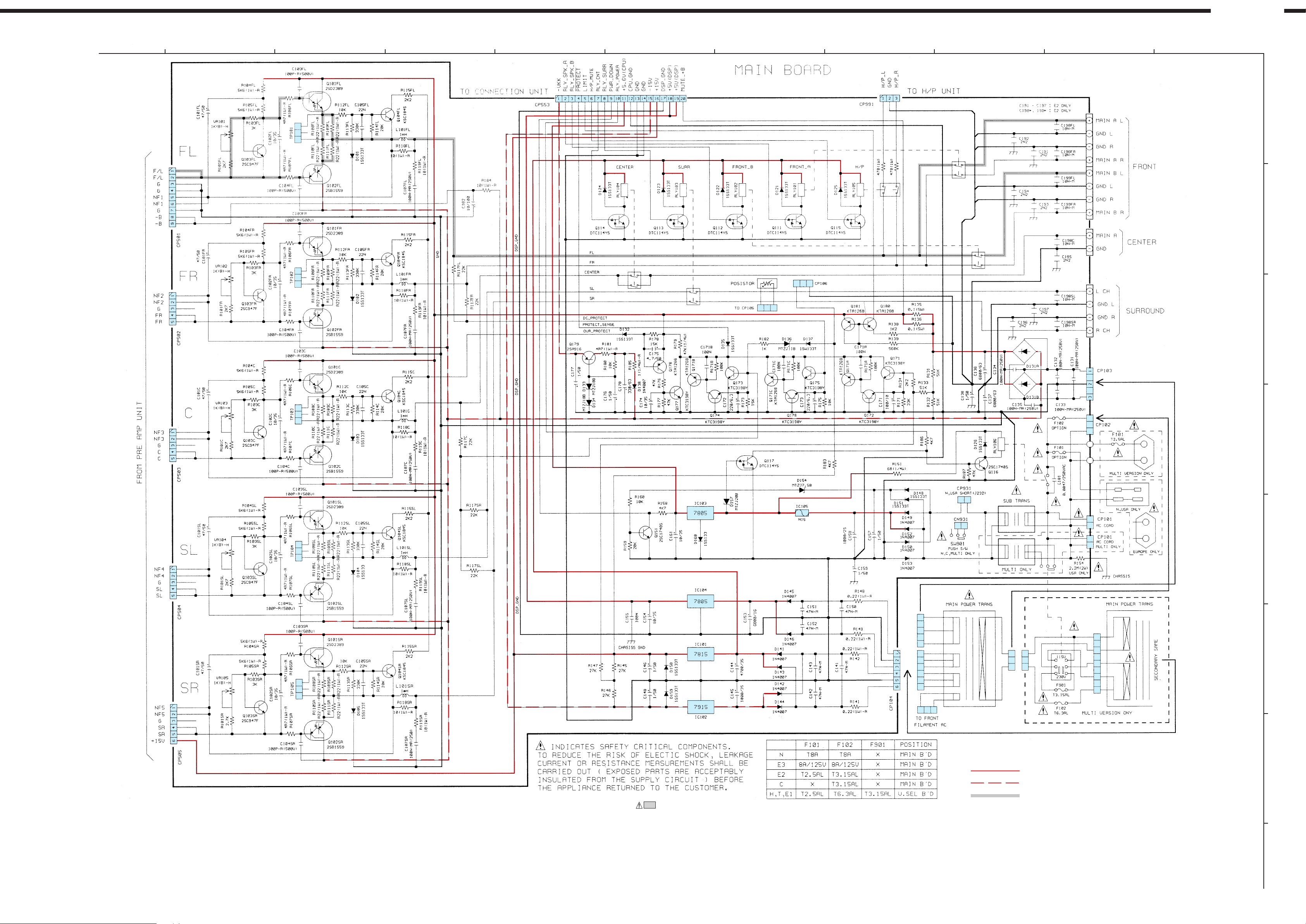
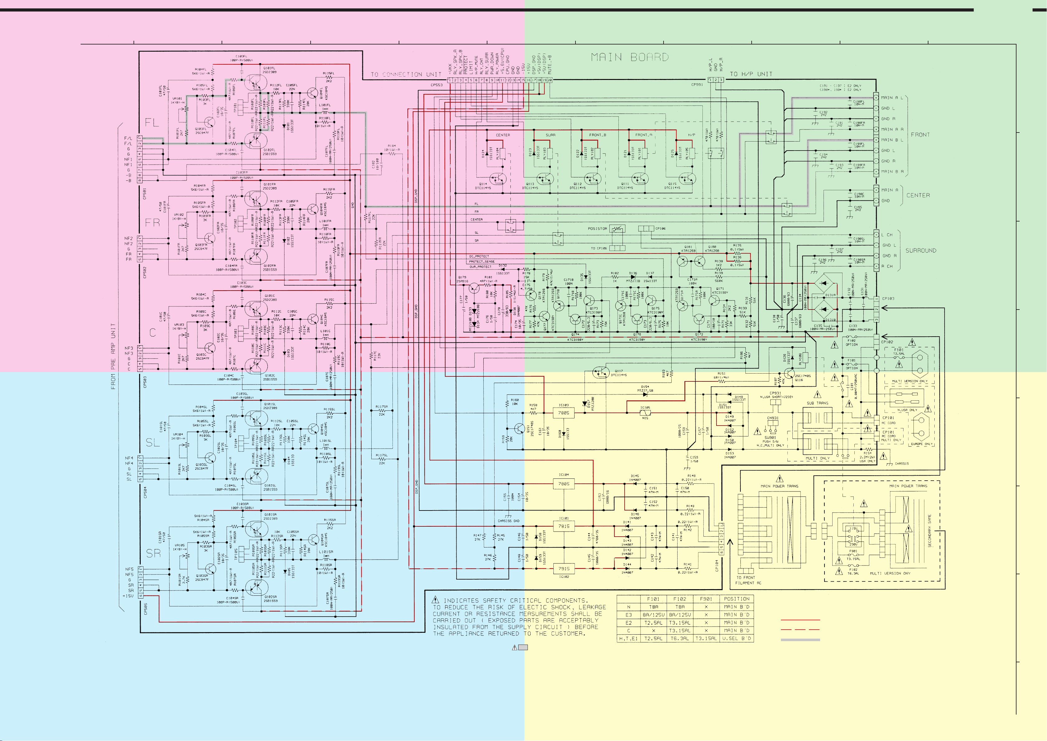
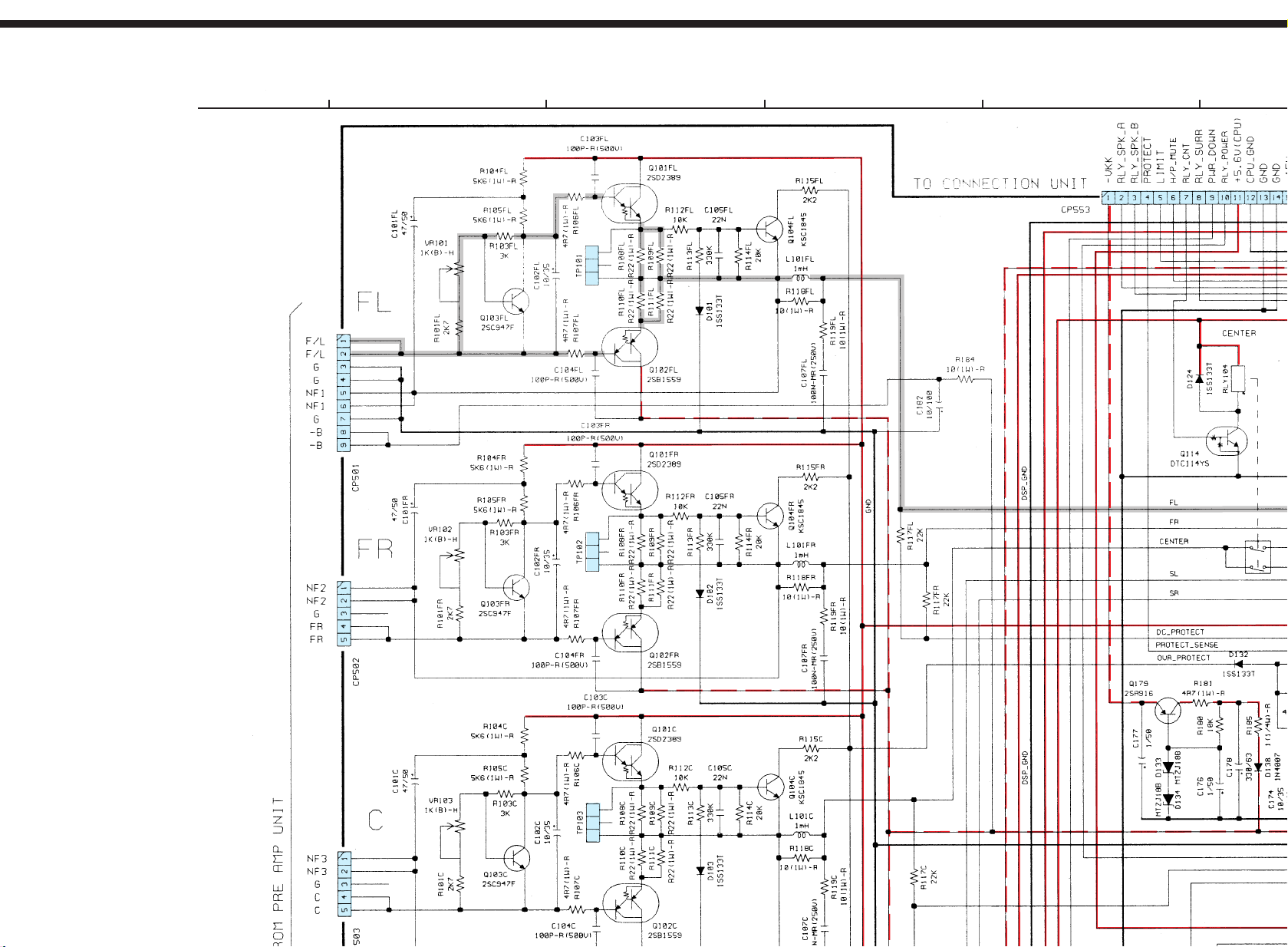
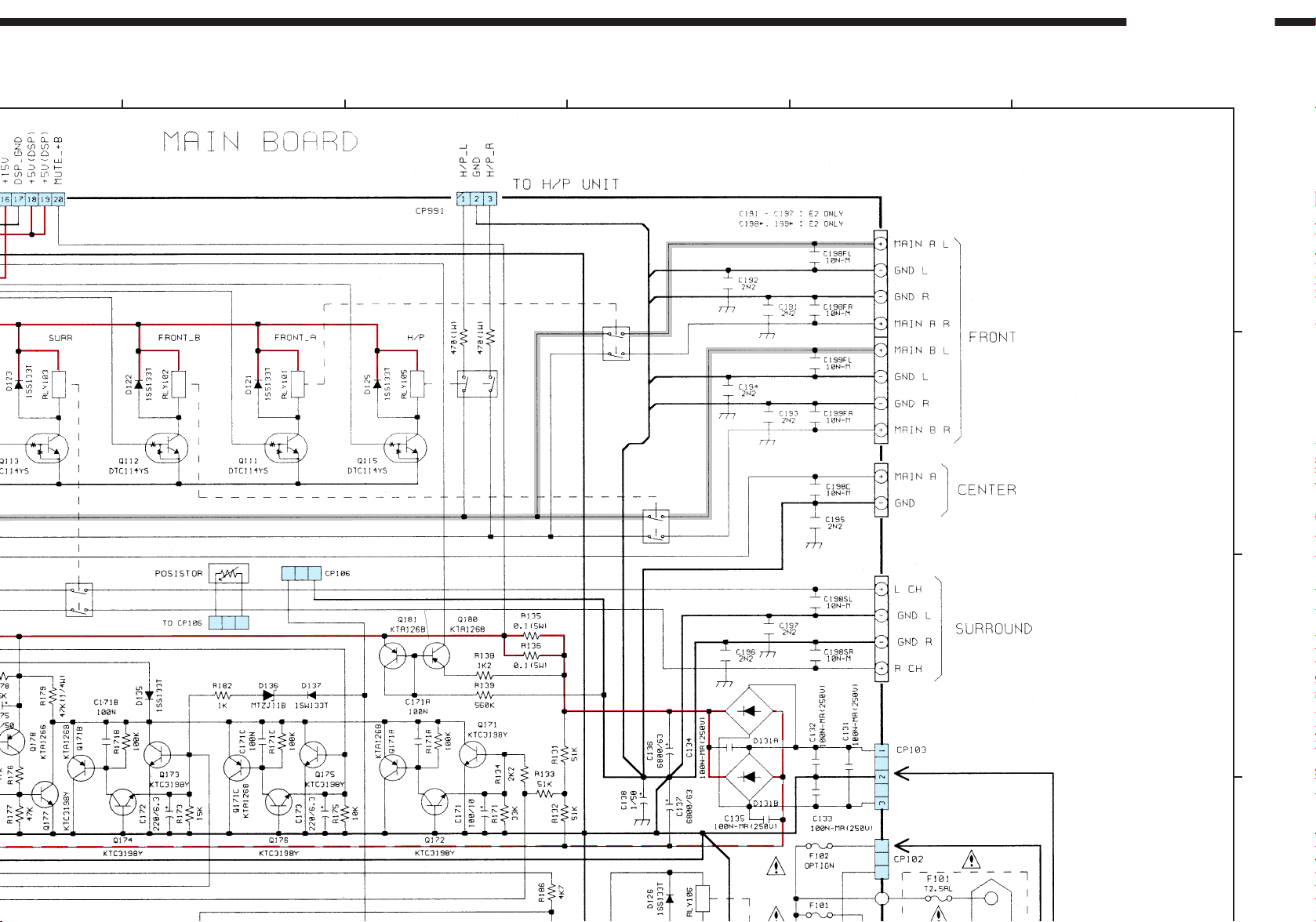
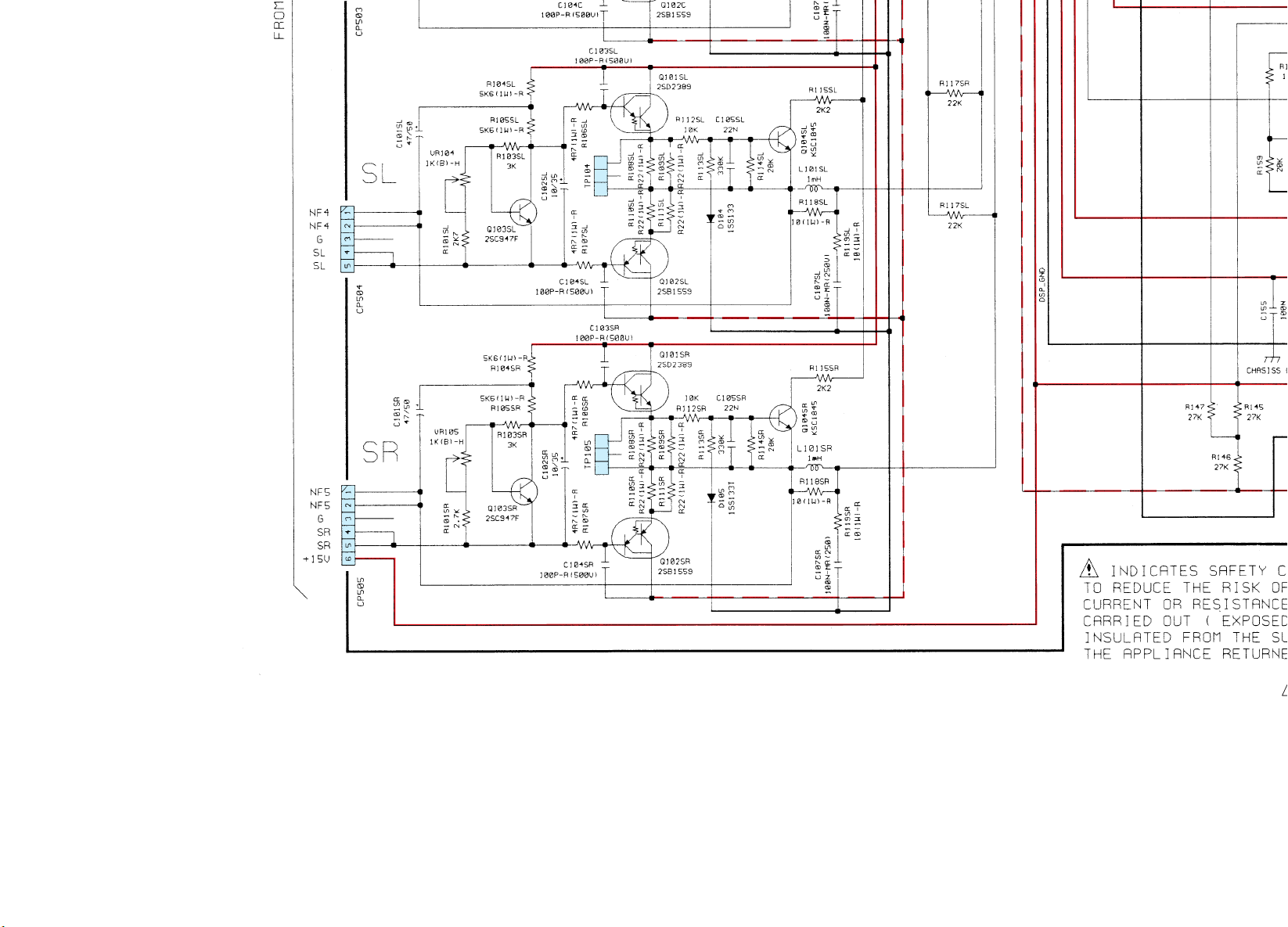
NOTICE
ALL RESISTANCE VALUES IN OHM. k=1,000 OHM M=1,000,000 OHM
ALL CAPACITANCE VALUES IN MICRO FARAD. P=MICRO-MICRO FARAD
EACH VOLTAGE AND CURRENT ARE MEASUERD AT MO SIGNAL INPUT
CONDITION.
CIRCUIT AND PARTS ARE SUBJECT TO CHANGE WITHOUT PRIOR
NOTICE.
WARNING:
Parts marked with this symbol have critical characteristics.
Use ONLY replacement parts recommended by the manufacture.
CAUTION:
Before returning the unit to the customer, make sure you make either (1) a
leakage current check or (2) a line to chassis resistance check. If the leakage
current exceeds 0.5 milliamps, or if the resistance from chassis to either side
of the power card is less than 460kohms, the unit is defective.
WARNING:
DO NOT return the unit to the customer until the problem is located and
corrected.
+ B LINE
-
B LINE
SIGNAL LINE
SCHEMATIC DIAGRAMS(5/7)
MAIN P.W.B. UNIT
F
G
H
46
Page 3
SCHEMATIC DIAGRAMS(5/7)
AVR-1602/682
321
A
A
4
5
6
7
8
9
10
11
A
B
B
B
C
D
E
C
C
NOTICE
ALL RESISTANCE VALUES IN OHM. k=1,000 OHM M=1,000,000 OHM
ALL CAPACITANCE VALUES IN MICRO FARAD. P=MICRO-MICRO FARAD
EACH VOLTAGE AND CURRENT ARE MEASUERD AT MO SIGNAL INPUT
CONDITION.
CIRCUIT AND PARTS ARE SUBJECT TO CHANGE WITHOUT PRIOR
NOTICE.
WARNING:
Parts marked with this symbol have critical characteristics.
Use ONLY replacement parts recommended by the manufacture.
CAUTION:
Before returning the unit to the customer, make sure you make either (1) a
leakage current check or (2) a line to chassis resistance check. If the leakage
current exceeds 0.5 milliamps, or if the resistance from chassis to either side
of the power card is less than 460kohms, the unit is defective.
WARNING:
DO NOT return the unit to the customer until the problem is located and
corrected.
D
D
+ B LINE
-
B LINE
SIGNAL LINE
SCHEMATIC DIAGRAMS(5/7)
MAIN P.W.B. UNIT
F
G
H
46
Page 4
SCHEMATIC DIAGRAMS(5/7)
321
4
5
Page 5
AVR-1602/682
6
7
8
9
10
11
A
B
C
D
Page 6
NOTICE
ALL RESISTANCE VALUES IN OHM. k=1,000 OHM M=1,000,000 OHM
ALL CAPACITANCE VALUES IN MICRO FARAD. P=MICRO-MICRO FARAD
EACH VOLTAGE AND CURRENT ARE MEASUERD AT MO SIGNAL INPUT
CONDITION.
CIRCUIT AND PARTS ARE SUBJECT TO CHANGE WITHOUT PRIOR
NOTICE.
WARNING:
Parts marked with this symbol have critical characteristics.
Use ONLY replacement parts recommended by the manufacture.
CAUTION:
Before returning the unit to the customer, make sure you make either (1) a
leakage current check or (2) a line to chassis resistance check. If the leakage
current exceeds 0.5 milliamps, or if the resistance from chassis to either side
of the power card is less than 460kohms, the unit is defective.
WARNING:
DO NOT return the unit to the customer until the problem is located and
corrected.
Page 7

E
F
+ B LINE
-
B LINE
SIGNAL LINE
SCHEMATIC DIAGRAMS(5/7)
MAIN P.W.B. UNIT
G
H
46
Page 8

SCHEMATIC DIAGRAMS(6/7)
AVR-1602/682
321
4
5
6
7
8
9
10
11
A
B
C
D
E
ALL RESISTANCE VALUES IN OHM. k=1,000 OHM M=1,000,000 OHM
ALL CAPACITANCE VALUES IN MICRO FARAD. P=MICRO-MICRO FARAD
EACH VOLTAGE AND CURRENT ARE MEASUERD AT MO SIGNAL INPUT
CONDITION.
CIRCUIT AND PARTS ARE SUBJECT TO CHANGE WITHOUT PRIOR
NOTICE.
WARNING:
Parts marked with this symbol have critical characteristics.
Use ONLY replacement parts recommended by the manufacture.
CAUTION:
Before returning the unit to the customer, make sure you make either (1) a
leakage current check or (2) a line to chassis resistance check. If the leakage
current exceeds 0.5 milliamps, or if the resistance from chassis to either side
of the power card is less than 460kohms, the unit is defective.
WARNING:
DO NOT return the unit to the customer until the problem is located and
corrected.
+ B LINE
-
B LINE
SCHEMATIC DIAGRAMS(6/7)
FRONT P.W.B. UNIT
TACT S/W P.W.B. UNIT
H/P & POWER S/W P.W.B. UNIT
F
G
H
47
Page 9

SCHEMATIC DIAGRAMS(6/7)
AVR-1602/682AVR-1602/682
321
A
A
4
5
6
7
8
9
10
11
A
B
B
B
C
D
E
C
C
ALL RESISTANCE VALUES IN OHM. k=1,000 OHM M=1,000,000 OHM
ALL CAPACITANCE VALUES IN MICRO FARAD. P=MICRO-MICRO FARAD
EACH VOLTAGE AND CURRENT ARE MEASUERD AT MO SIGNAL INPUT
CONDITION.
CIRCUIT AND PARTS ARE SUBJECT TO CHANGE WITHOUT PRIOR
NOTICE.
WARNING:
Parts marked with this symbol have critical characteristics.
Use ONLY replacement parts recommended by the manufacture.
CAUTION:
Before returning the unit to the customer, make sure you make either (1) a
leakage current check or (2) a line to chassis resistance check. If the leakage
current exceeds 0.5 milliamps, or if the resistance from chassis to either side
of the power card is less than 460kohms, the unit is defective.
WARNING:
DO NOT return the unit to the customer until the problem is located and
corrected.
D
D
+ B LINE
-
B LINE
SCHEMATIC DIAGRAMS(6/7)
FRONT P.W.B. UNIT
TACT S/W P.W.B. UNIT
H/P & POWER S/W P.W.B. UNIT
F
G
H
47
Page 10

SCHEMATIC DIAGRAMS(6/7)
321
4
5
Page 11

AVR-1602/682
6
7
8
9
10
11
A
B
C
D
Page 12

ALL RESISTANCE VALUES IN OHM. k=1,000 OHM M=1,000,000 OHM
ALL CAPACITANCE VALUES IN MICRO FARAD. P=MICRO-MICRO FARAD
EACH VOLTAGE AND CURRENT ARE MEASUERD AT MO SIGNAL INPUT
CONDITION.
CIRCUIT AND PARTS ARE SUBJECT TO CHANGE WITHOUT PRIOR
NOTICE.
Page 13

E
F
WARNING:
Parts marked with this symbol have critical characteristics.
Use ONLY replacement parts recommended by the manufacture.
CAUTION:
Before returning the unit to the customer, make sure you make either (1) a
leakage current check or (2) a line to chassis resistance check. If the leakage
current exceeds 0.5 milliamps, or if the resistance from chassis to either side
of the power card is less than 460kohms, the unit is defective.
WARNING:
DO NOT return the unit to the customer until the problem is located and
corrected.
+ B LINE
-
B LINE
SCHEMATIC DIAGRAMS(6/7)
FRONT P.W.B. UNIT
TACT S/W P.W.B. UNIT
H/P & POWER S/W P.W.B. UNIT
G
H
47
Page 14

SCHEMATIC DIAGRAMS(7/7)
AVR-1602/682
321
4
5
6
7
8
9
10
11
A
B
C
D
E
NOTICE
ALL RESISTANCE VALUES IN OHM. k=1,000 OHM M=1,000,000 OHM
ALL CAPACITANCE VALUES IN MICRO FARAD. P=MICRO-MICRO FARAD
EACH VOLTAGE AND CURRENT ARE MEASUERD AT MO SIGNAL INPUT
CONDITION.
CIRCUIT AND PARTS ARE SUBJECT TO CHANGE WITHOUT PRIOR
NOTICE.
WARNING:
Parts marked with this symbol have critical characteristics.
Use ONLY replacement parts recommended by the manufacture.
CAUTION:
Before returning the unit to the customer, make sure you make either (1) a
leakage current check or (2) a line to chassis resistance check. If the leakage
current exceeds 0.5 milliamps, or if the resistance from chassis to either side
of the power card is less than 460kohms, the unit is defective.
WARNING:
DO NOT return the unit to the customer until the problem is located and
corrected.
+ B LINE
SIGNAL LINE
SCHEMATIC DIAGRAMS(7/7)
TUNER P.W.B. UNIT
F
G
H
48
Page 15

SCHEMATIC DIAGRAMS(7/7)
AVR-1602/682
321
A
A
4
5
6
7
8
9
10
11
A
B
B
B
C
D
E
C
C
NOTICE
ALL RESISTANCE VALUES IN OHM. k=1,000 OHM M=1,000,000 OHM
ALL CAPACITANCE VALUES IN MICRO FARAD. P=MICRO-MICRO FARAD
EACH VOLTAGE AND CURRENT ARE MEASUERD AT MO SIGNAL INPUT
CONDITION.
CIRCUIT AND PARTS ARE SUBJECT TO CHANGE WITHOUT PRIOR
NOTICE.
WARNING:
Parts marked with this symbol have critical characteristics.
Use ONLY replacement parts recommended by the manufacture.
CAUTION:
Before returning the unit to the customer, make sure you make either (1) a
leakage current check or (2) a line to chassis resistance check. If the leakage
current exceeds 0.5 milliamps, or if the resistance from chassis to either side
of the power card is less than 460kohms, the unit is defective.
WARNING:
DO NOT return the unit to the customer until the problem is located and
corrected.
D
D
+ B LINE
SIGNAL LINE
SCHEMATIC DIAGRAMS(7/7)
TUNER P.W.B. UNIT
F
G
H
48
Page 16

SCHEMATIC DIAGRAMS(7/7)
321
4
5
Page 17

AVR-1602/682
6
7
8
9
10
11
A
B
C
D
Page 18

NOTICE
ALL RESISTANCE VALUES IN OHM. k=1,000 OHM M=1,000,000 OHM
ALL CAPACITANCE VALUES IN MICRO FARAD. P=MICRO-MICRO FARAD
EACH VOLTAGE AND CURRENT ARE MEASUERD AT MO SIGNAL INPUT
CONDITION.
CIRCUIT AND PARTS ARE SUBJECT TO CHANGE WITHOUT PRIOR
NOTICE.
WARNING:
Parts marked with this symbol have critical characteristics.
Use ONLY replacement parts recommended by the manufacture.
CAUTION:
Before returning the unit to the customer, make sure you make either (1) a
leakage current check or (2) a line to chassis resistance check. If the leakage
current exceeds 0.5 milliamps, or if the resistance from chassis to either side
of the power card is less than 460kohms, the unit is defective.
WARNING:
DO NOT return the unit to the customer until the problem is located and
corrected.
Page 19

E
G
F
+ B LINE
SIGNAL LINE
SCHEMATIC DIAGRAMS(7/7)
TUNER P.W.B. UNIT
H
48
 Loading...