

Page 1
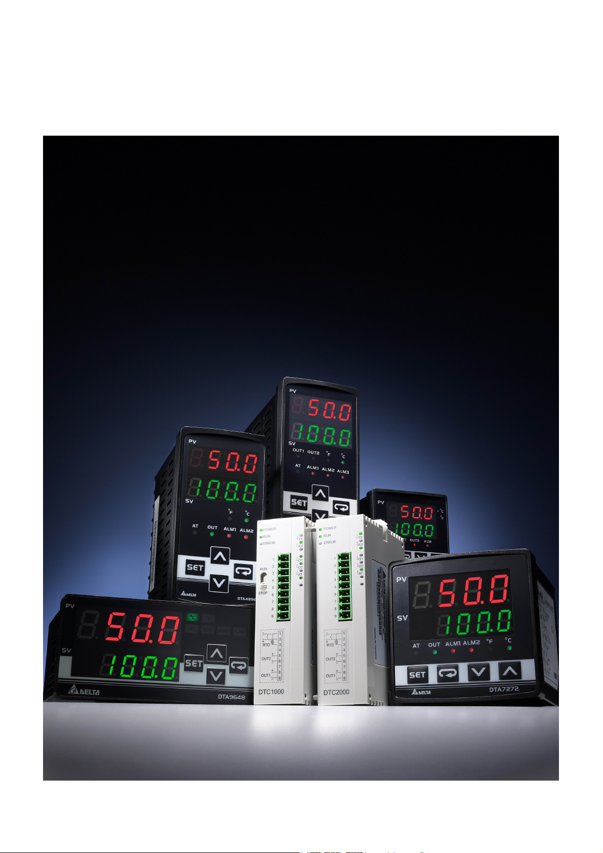
Delta Temperature Controller
User Manual
Page 2
Delta Temperature Controller User Manual
Foreword
The user manual details the process of using Delta DT series temperature controllers step by step
for beginners to easily set up all kinds of parameters in a short time.
CHAPTER 1: DEFAULT SETTINGS OF PARAMETERS
1.1 Default Settings in Temperature Controller 3
1.2 How to Return to Default Settings in DTA 4
1.3 How to Return to Default Settings in DTB 7
1.4 How to Return to Default Settings in DTC 10
CHAPTER 2: CONTROL MODES IN DTA
2.1 ON/OFF 11
2.2 MANUAL
2.3 PID
CHAPTER 3: CONTROL MODES IN DTB
3.1 ON/OFF 15
3.2 MANUAL 16
3.3 PID 17
3.4 PID PROG 19
CHAPTER 4: CONTROL MODES IN DTC
4.1 ON/OFF 21
4.2 MANUAL 23
4.3 PID 24
4.4 PID PROG
12
13
25
2007-09-17 - 2 - © DELTA ELECTRONICS, INC. ALL RIGHTS RESERVED
Page 3
Delta Temperature Controller User Manual
CHAPTER 1: DEFAULT SETTINGS OF PARAMETERS
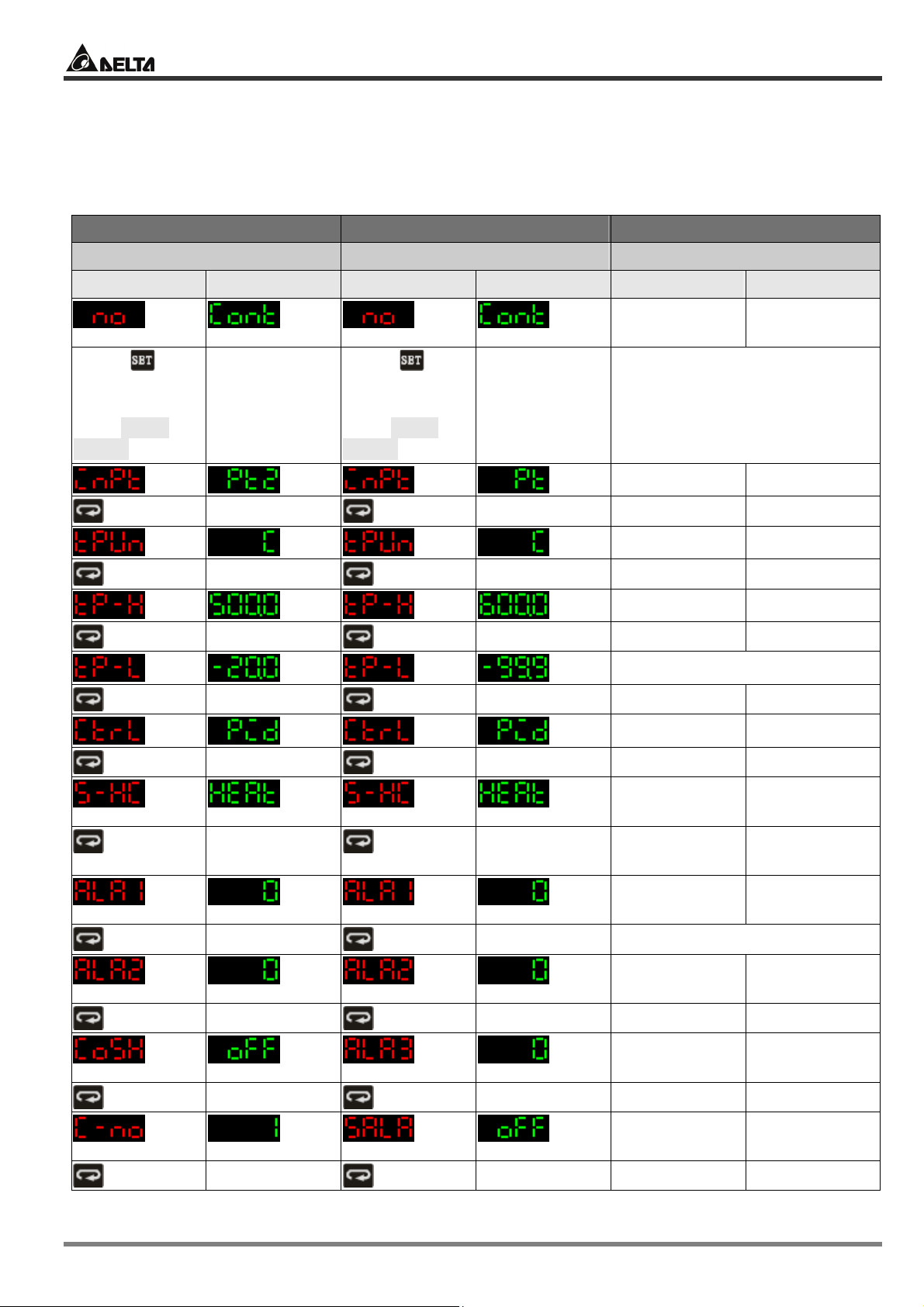
1.1 Default Settings in Temperature Controller
DTA DTB DTC
Model: DTA4896R1 Model: DTB4896RR Model: DTC1000R
PV SV PV SV PV SV
Press for
more than 3
seconds to
enter initial
setting mode
Not connected
0.0
to sensor
Press for
more than 3
seconds to
Set up control modes
enter initial
setting mode
Control mode PID control
Run/stop Run
Output 1 Heating
Output 2 Heating
Status of key Normal
Auto-tuning End
Set up temperature
Input type
Input unit
Set value
Maximum input
temperature
PT100
°C
0.0
600.0
© DELTA ELECTRONICS, INC. ALL RIGHTS RESERVED - 3 - 2007-09-17
Minimum input
temperature
Position of
decimal point
-20.0
1 digit after
decimal point
Set up PID parameter
Proportional
band (P)
Integral time (I)
Derivative time
(D)
Control cycle 1
Integral default
value
Control cycle 2
47.6
260
41
20
0.0
20
Page 4
Delta Temperature Controller User Manual
DTA DTB DTC
Model: DTA4896R1 Model: DTB4896RR Model: DTC1000R
PV SV PV SV PV SV
Back to top
Back to top
Adjust temperature
Input
0.0
compensation
Password of DTC
Level 1
Disabled
password
Level 2
Disabled
password
Level 3
Disabled
password
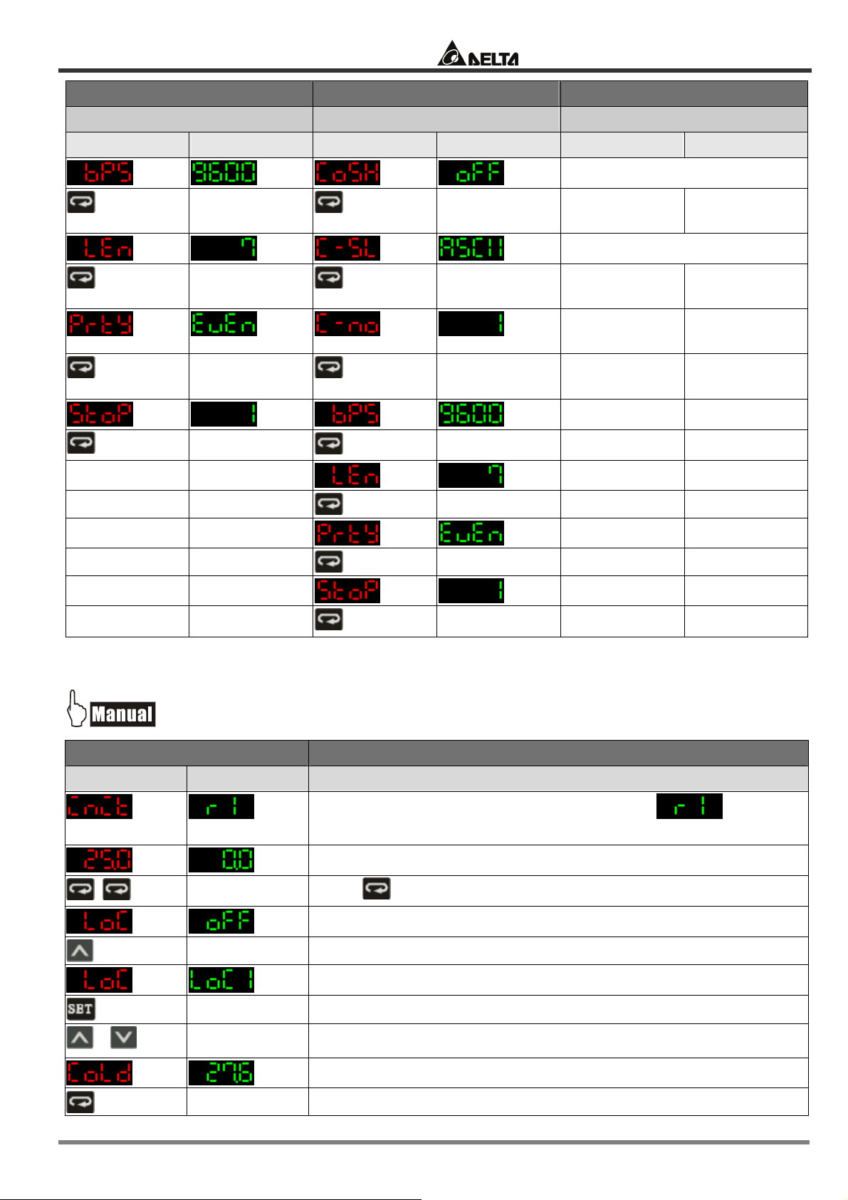
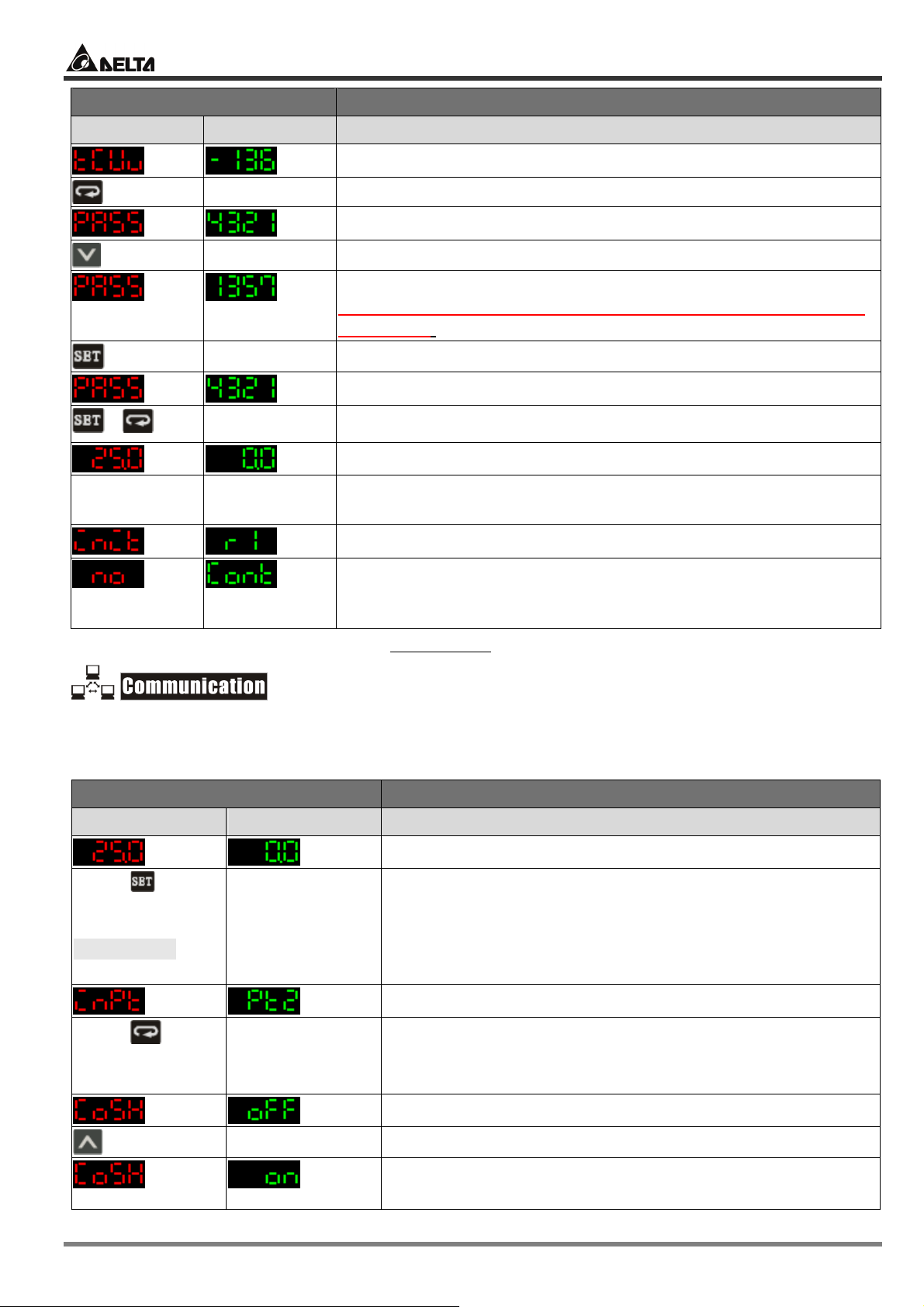
1.2 How to Return to Default Settings in DTA
Display Explanations
PV SV Status of the temperature controller
+
Press “up” and “down” keys together for 1 second.
Temporary display when DTA is switched on: = relay
output with RS-485 communication.
Example displayed values
Press twice
Key-locked function
Select Lock 1
Default value
2007-09-17 - 4 - © DELTA ELECTRONICS, INC. ALL RIGHTS RESERVED
Page 5
Delta Temperature Controller User Manual
Display Explanations
PV SV Status of the temperature controller
+
Switch off DTA
and re-power it.
Default value
Press “down” key continuously until the value reaches 1357
(please DO NOT modify this value; otherwise system confusion
may occur).
Press the two keys together once to return to main screen.
Main screen
Return to default value. The default sensor is PT100, which will be
displayed when DTA is not connected to a sensor or
thermocouple.
The model adopted in this example is: DTA4896R1 with firmware V3.50.
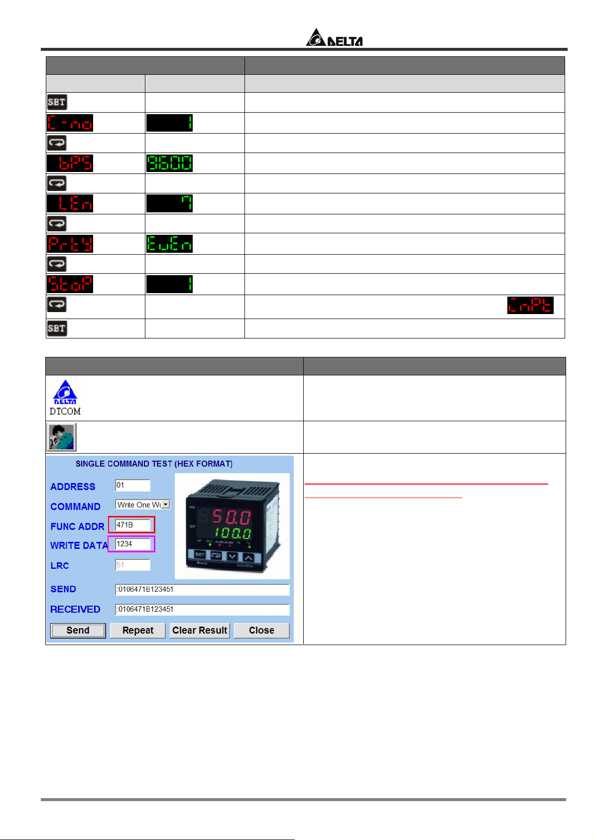
1. Make sure RS-485 hardware communication cable in DTA has been connected to the computer.
2. Make sure the communication parameters in DTA are consistent with those in the computer.
Display Explanations
PV SV Status of the temperature controller
Press for
more than 3
seconds to enter
initial setting
mode
Press
continuously for 8
times
Example displayed values
Example displayed value: PT100 Sensor
ON/OFF of communication write-in
OFF: communication write-in disabled
ON: communication write-in enabled
© DELTA ELECTRONICS, INC. ALL RIGHTS RESERVED - 5 - 2007-09-17
Page 6
Delta Temperature Controller User Manual
Display Explanations
PV SV Status of the temperature controller
Back to top
Return to PV/SV screen in the operation mode
DTCOM Software Explanations
Communication address
Communication speed
Data length (in bits)
Parity bit
Stop bit
Return to the first item in the initial setting mode:
Execute DTCOM Software
Select “SINGLE COMMAND TEST”
Function address = 471B; Write data =1234.
(Please DO NOT modify this value; otherwise
system confusion may occur.)
2007-09-17 - 6 - © DELTA ELECTRONICS, INC. ALL RIGHTS RESERVED
Page 7
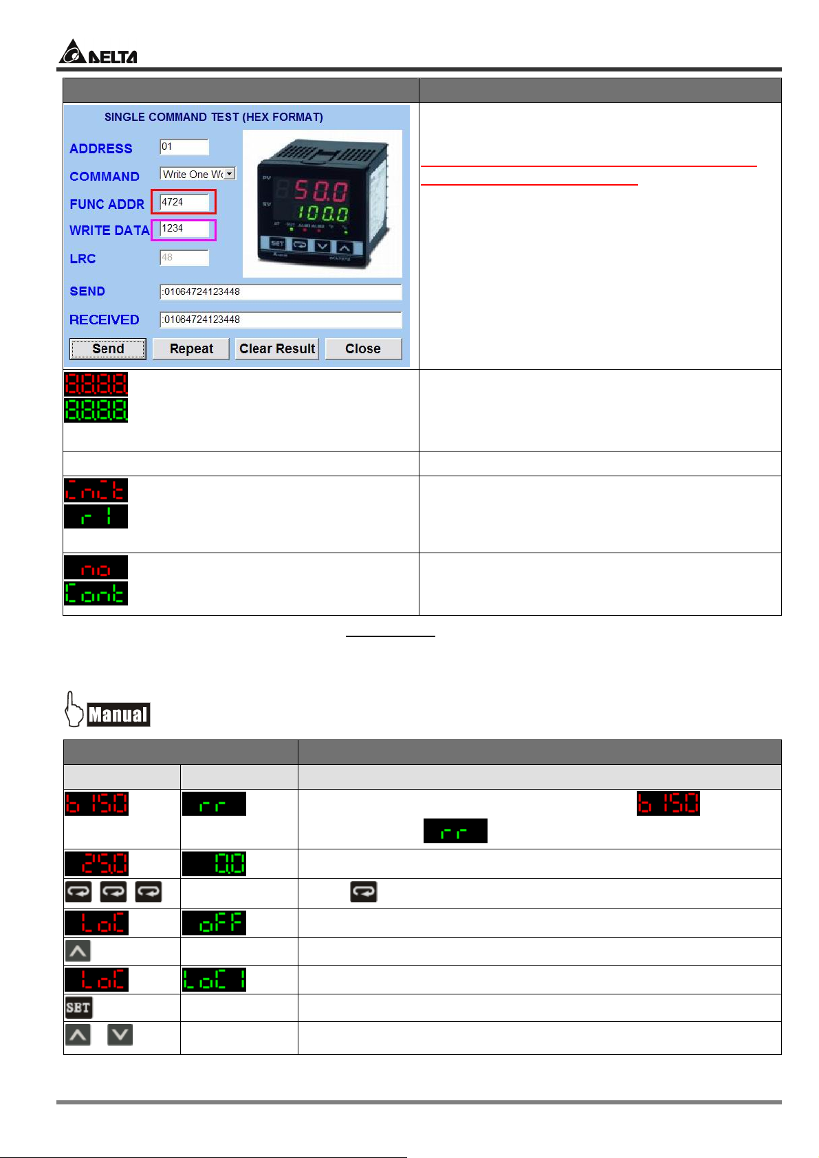
Delta Temperature Controller User Manual
DTCOM Software Explanations
Clear the user’s settings.
Function address = 4724; Write data = 1234
(Please DO NOT modify this value; otherwise
system confusion may occur.)
Switch off DTA and re-power it.
The model adopted in this example is: DTA4896R1 with firmware V3.50.
After the above procedures are completed, DTA
will display the information on the left hand side,
representing that DTA has return to default
settings successfully.
Return to default value. The default sensor is
PT100, which will be displayed when DTA is not
connected to a sensor or thermocouple.
1.3 How to Return to Default Settings in DTB
Display Explanations
PV SV Status of the temperature controller
+
© DELTA ELECTRONICS, INC. ALL RIGHTS RESERVED - 7 - 2007-09-17
Press “up” and “down” key together for 1 second.
Temporary display when DTB is switched on:
firmware V1.50;
Example displayed value
Press for 3 times
Key-locked function
Select Lock 1
= relay output for OUT1/OUT2
=
Page 8
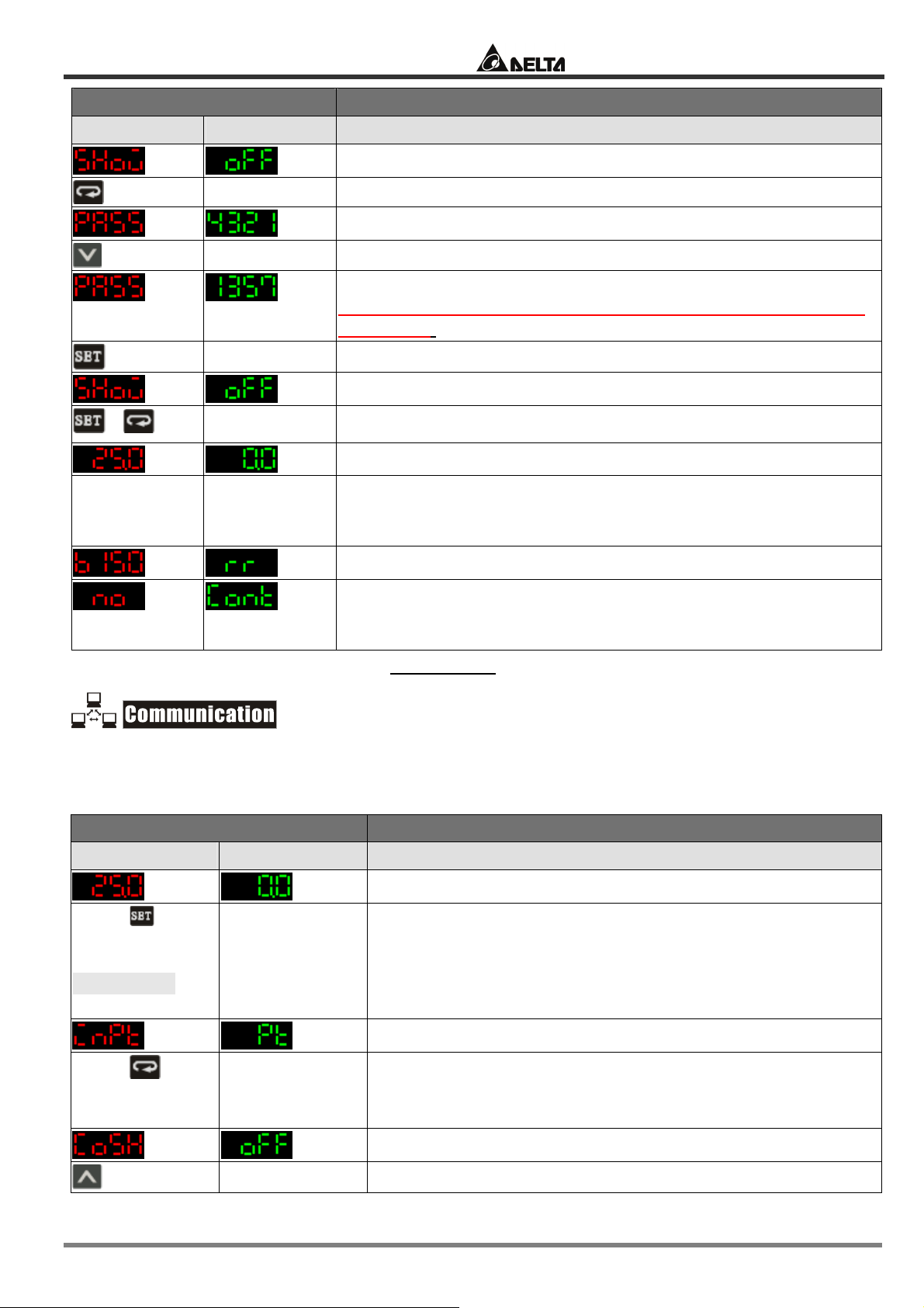
Delta Temperature Controller User Manual
Display Explanations
PV SV Status of the temperature controller
+
Switch off DTB
and re-power
it.
Press “down” key continuously until the value reaches 1357
(please DO NOT modify this value; otherwise system confusion
may occur).
Press the two keys together once to return to main screen.
Main screen
Return to default value. The default sensor is PT100, which will be
displayed when DTB is not connected to a sensor or
thermocouple.
The model adopted in this example is: DTB4896RR with firmware V1.50.
1. Make sure RS-485 hardware communication cable in DTB has been connected to the computer.
2. Make sure the communication parameters in DTB are consistent with those in the computer.
Display Explanations
PV SV Status of the temperature controller
Press for
more than 3
seconds to enter
initial setting
mode
Press
continuously for
10 times
Example displayed value
Example displayed value: PT100 Sensor
2007-09-17 - 8 - © DELTA ELECTRONICS, INC. ALL RIGHTS RESERVED
ON/OFF of communication write-in
Page 9
Delta Temperature Controller User Manual
Display Explanations
PV SV Status of the temperature controller
back to top
OFF: communication write-in disabled
ON: communication write-in enabled
ASCII or RTU
Communication address
Communication speed
Data length (in bits)
Parity bit
Stop bit
Return to the first item in the initial setting mode:
Return to PV/SV screen in the operation mode
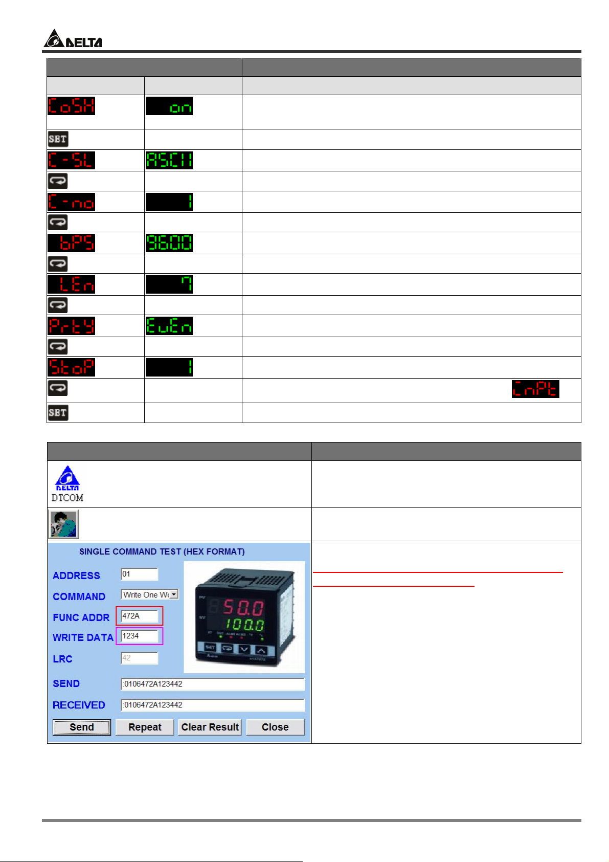
DTCOM Software Explanations
Execute DTCOM Software
Select “SINGLE COMMAND TEST”
Function address = 472A; Write data =1234
(Please DO NOT modify this value; otherwise
system confusion may occur.)
© DELTA ELECTRONICS, INC. ALL RIGHTS RESERVED - 9 - 2007-09-17
Page 10

Delta Temperature Controller User Manual
DTCOM Software Explanations
Clear the user’s settings.
Function address = 474E; Write data = 1234
(Please DO NOT modify this value; otherwise
system confusion may occur.)
Switch off DTB and re-power it.
The model adopted in this example is: DTB4896RR with firmware V1.50.
After the above procedures are completed, DTB
will display the information on the left hand side,
representing that DTB has return to default
settings successfully.
Return to default value. The default sensor is
PT100, which will be displayed when DTC is not
connected to a sensor or thermocouple.
1.4 How to Return to Default Settings in DTC
1. Make sure RS-485 hardware communication cable in DTC has been connected to the computer.
2. Make sure the communication parameters in DTC are consistent with those in the computer.
DTCOM Software Explanations
Execute DTCOM Software
Select “SINGLE COMMAND TEST”
2007-09-17 - 10 - © DELTA ELECTRONICS, INC. ALL RIGHTS RESERVED
Page 11

Delta Temperature Controller User Manual
DTCOM Software Explanations
Function address = 472A; Write data = 1234
(Please DO NOT modify this value; otherwise
system confusion may occur.)
Clear the user’s settings.
Function address = 474E; Write data = 1234
(Please DO NOT modify this value; otherwise
system confusion may occur.)
Switch off DTC and re-power it. Return to default settings
The model adopted in this example is: DTC1000R with firmware V1.40.
CHAPTER 2: CONTROL MODES IN DTA
2.1 ON/OFF
There are three control modes in DTA: ON/OFF, MANUAL and PID. First, press for 3 seconds
to enter the “initial setting” mode. See below for how to switch between each mode:
© DELTA ELECTRONICS, INC. ALL RIGHTS RESERVED - 11 - 2007-09-17
Page 12

Delta Temperature Controller User Manual
Display Explanations
PV SV Status of the temperature controller
Press for
more than 3
seconds to enter
initial setting
mode
Message displayed when DTA has not yet been connected
to a sensor.
Select the sensor connected. Default = PT100
Temperature unit. Default = °C
Upper limit of temperature range
Lower limit of temperature range
The control modes include: PID, ON/OFF, MANUAL.
Default = PID. Select “ON/OFF” here.
Back to top
Select heating or cooling mode. Default = heating
Set up Alarm mode 1. Default = alarm output disabled
Set up Alarm mode 2. Default = alarm output disabled
ON/OFF of communication write-in. Default = OFF
Communication address
Communication speed
Data length (in bits)
Parity bit
Stop bit
2007-09-17 - 12 - © DELTA ELECTRONICS, INC. ALL RIGHTS RESERVED
Page 13

Delta Temperature Controller User Manual
Parameters relevant to ON/OFF control
Press in the main screen of DTA to enter the “regulation mode”.
Display Explanations
PV SV Status of the temperature controller
or
Set up hysteresis. Default = heating hysteresis. Can be set as
cooling hysteresis as well. Both default values are “0”.
2.2 MANUAL
Press for 3 seconds in the main screen to enter the “initial setting mode”. Press several
times until the parameter is displayed.
Display Explanations
PV SV Status of the temperature controller
Back
to top
Parameters relevant to MANUAL control
Press in the main screen of DTA to enter the “regulation mode”.
Display Explanations
The control modes include: PID, ON/OFF, MANUAL.
Default = PID. Select “MANUAL” here.
Press to return to the main screen.
PV SV Status of the temperature controller
or
Set up heating or cooling control cycle. Default = heating, 20
seconds per cycle.
Press in the main screen of DTA to enter the “operation mode”.
Display Explanations
PV SV Status of the temperature controller
Run/stop
Key-locked function
Manually adjust the output percentage. Assume the percentage
value = 50 and the cycle = 20 seconds plus heating control, the
system will conduct heating output for 10 seconds and stop for the
other 10 seconds.
2.3 PID
Press for 3 seconds in the main screen to enter the “initial setting mode”. Press several
times until the parameter is displayed.
© DELTA ELECTRONICS, INC. ALL RIGHTS RESERVED - 13 - 2007-09-17
Page 14

Delta Temperature Controller User Manual
Display Explanations
PV SV Status of the temperature controller
Back to
top
Parameters relevant to PID control
Press in the main screen of DTA to enter the “regulation mode”.
PV SV Status of the temperature controller
Display Explanations
The control modes include: PID, ON/OFF, MANUAL.
Default = PID. Select “PID” here.
Press to return to the main screen.
ON/OFF of auto-tuning
Default value for proportional control
Default value for integral control
Default value for derivative control
Default integral value
Heating/cooling control cycle
Temperature inaccuracy adjustment value
Press in the main screen of DTA to enter the “operation mode”.
Display Explanations
PV SV Status of the temperature controller
Run/stop
Key-locked function
Output volume. In PID control mode, this is a read-only parameter
and cannot be modified.
2007-09-17 - 14 - © DELTA ELECTRONICS, INC. ALL RIGHTS RESERVED
Page 15

Delta Temperature Controller User Manual
CHAPTER 3: CONTROL MODES IN DTB
3.1 ON/OFF
There are four control modes in DTB: ON/OFF, MANUAL, PID and PID PROG. To switch to
ON/OFF mode, first press for 3 seconds to enter the “initial setting” mode. See below for how
to switch between each mode:
Display Explanations
PV SV Status of the temperature controller
Press for
more than 3
seconds to
enter initial
setting mode
Message displayed when DTB has not yet been connected to a
sensor.
Select the sensor connected. Default = PT100
Temperature unit. Default = °C
Upper limit of temperature range
Lower limit of temperature range
The control modes include: ON/OFF, MANUAL, PID and PID
PROG. Default = PID. Select “ON/OFF” here.
© DELTA ELECTRONICS, INC. ALL RIGHTS RESERVED - 15 - 2007-09-17
Select heating/cooling/heating 1 cooling 2/heating 2 cooling 1.
Default = heating
Set up Alarm mode 1. Default = alarm output disabled.
Page 16

Delta Temperature Controller User Manual
Display Explanations
PV SV Status of the temperature controller
Back to
top
Set up Alarm mode 2. Default = alarm output disabled.
Set up Alarm mode 3. Default = alarm output disabled.
Set up system alarm
ON/OFF of communication write-in. Default = OFF
Select communication format
Communication address
Communication speed
Data length (in bits)
Parity bit
Stop bit
Parameters relevant to ON/OFF control
Press
in the main screen of DTB to enter the “regulation mode”.
Display Explanations
PV SV Status of the temperature controller
or
Set up hysteresis. Default = heating hysteresis. Can be set as
cooling hysteresis as well. Both default values are “0”.
3.2 MANUAL
Press for 3 seconds in the main screen to enter the “initial setting mode”. Press several
times until the parameter
2007-09-17 - 16 - © DELTA ELECTRONICS, INC. ALL RIGHTS RESERVED
is displayed.
Page 17

Delta Temperature Controller User Manual
Display Explanations
PV SV Status of the temperature controller
The control modes include: ON/OFF, MANUAL, PID and PID
PROG. Default = PID. Select “MANUAL” here.
Press to return to the main screen.
Back to
top
Parameters relevant to MANUAL control
Press in the main screen of DTB to enter the “regulation mode”.
Display Explanations
PV SV Status of the temperature controller
or
Set up heating or cooling control cycle. Default = heating, 20
seconds per cycle.
Press in the main screen of DTB to enter the “operation mode”.
Display Explanations
PV SV Status of the temperature controller
Run/stop
Set up the position of decimal point.
1 = value with decimal point; 2 = value without decimal point
Key-locked function
Manually adjust the output percentage. Assume the percentage
value = 50 and the cycle = 20 seconds plus heating control, the
system will conduct heating output for 10 seconds and stop for
the other 10 seconds.
3.3 PID
Press for 3 seconds in the main screen to enter the “initial setting mode”. Press several
times until the parameter is displayed.
Display Explanations
PV SV Status of the temperature controller
The control modes include: ON/OFF, MANUAL, PID and PID PROG.
Default = PID.
Press to return to the main screen.
top
Back to
Parameters relevant to PID control
Press in the main screen of DTB to enter the “regulation mode”.
© DELTA ELECTRONICS, INC. ALL RIGHTS RESERVED - 17 - 2007-09-17
Page 18

Display Explanations
PV SV Status of the temperature controller
Delta Temperature Controller User Manual
ON/OFF of auto-tuning
The 0th PID parameter. There are 4 groups of PID parameters
built in DTB. When the parameter is set ass PID4, the system
will automatically adopt the PID value of the current temperature
closest to PID0 ~ 3.
The 0th SV
The 0th default value for proportional control
The 0th default value for integral control
The 0th default value for derivative control
The 0th default integral value
Heating/cooling control cycle
Temperature inaccuracy adjustment value
Press in the main screen of DTB to enter the “operation mode”.
Display Explanations
PV SV Status of the temperature controller
Run/stop
Set up the position of decimal point
Key-locked function
Output volume. In PID control mode, this is a read-only
parameter and cannot be modified.
2007-09-17 - 18 - © DELTA ELECTRONICS, INC. ALL RIGHTS RESERVED
Page 19
Delta Temperature Controller User Manual
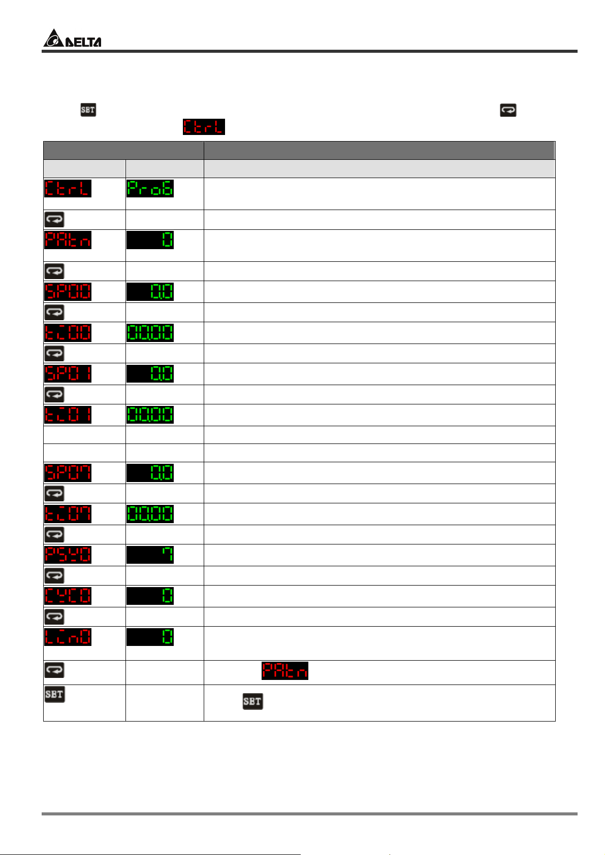
3.4 PID PROG
Press for 3 seconds in the main screen to enter the “initial setting mode”. Press several
times until the parameter is displayed.
Display Explanations
PV SV Status of the temperature controller
… … …
… … …
The control modes include: ON/OFF, MANUAL, PID and PID
PROG. Default = PID. Select “PID PROG” here.
DTB offers 8 patterns and 8 steps for each pattern, totaling 64
steps. Range of a pattern: OFF ~ 7. OFF = the function disabled.
Temperature SV for pattern 0 and step 0
Time SV for pattern 0 and step 0
Temperature SV for pattern 0 and step 1
Time SV for pattern 0 and step 1
Temperature SV for pattern 0 and step 7
Time SV for pattern 0 and step 7
Actual number of steps executed in pattern 0
Actual number of loops executed in pattern 0
Pattern linked after the execution of pattern 0 is completed.
OFF = end of linking patterns
Back to
top
Return to the main screen to switch to the functions below.
© DELTA ELECTRONICS, INC. ALL RIGHTS RESERVED - 19 - 2007-09-17
Return to
Press to return to the main screen.
Page 20

Display Explanations
PV SV Status of the temperature controller
Delta Temperature Controller User Manual
Remaining time in the current step
Target temperature for the current execution
The pattern currently executed
+
+
+
Parameters relevant to PID PROG control
Press in the main screen of DTB to enter the “regulation mode”.
Display Explanations
PV SV Status of the temperature controller
The 0th PID parameter. There are 4 groups of PID parameters
built in DTB. When the parameter is set ass PID4, the system will
automatically adopt the PID value of the current temperature
closest to PID0 ~ 3.
The 0th SV
The 0th default value for proportional control
The 0th default value for integral control
The 0th default value for derivative control
The 0th default integral value
Heating/cooling control cycle
Temperature inaccuracy adjustment value
Press in the main screen of DTB to enter the “operation mode”.
Display Explanations
PV SV Status of the temperature controller
/ /
Stop/run/program stop/program hold。
Program stop: Run the system again, and DTB will start from
/
the initial step.
Program hold: Run the system again, and DTB will follow and
start from the previous step.
2007-09-17 - 20 - © DELTA ELECTRONICS, INC. ALL RIGHTS RESERVED
Page 21

Delta Temperature Controller User Manual
Display Explanations
PV SV Status of the temperature controller
Set up the position of decimal point
Key-locked function
Output volume. In PID PROG control mode, this is a read-only
parameter and cannot be modified.
CHAPTER 4: CONTROL MODES IN DTC
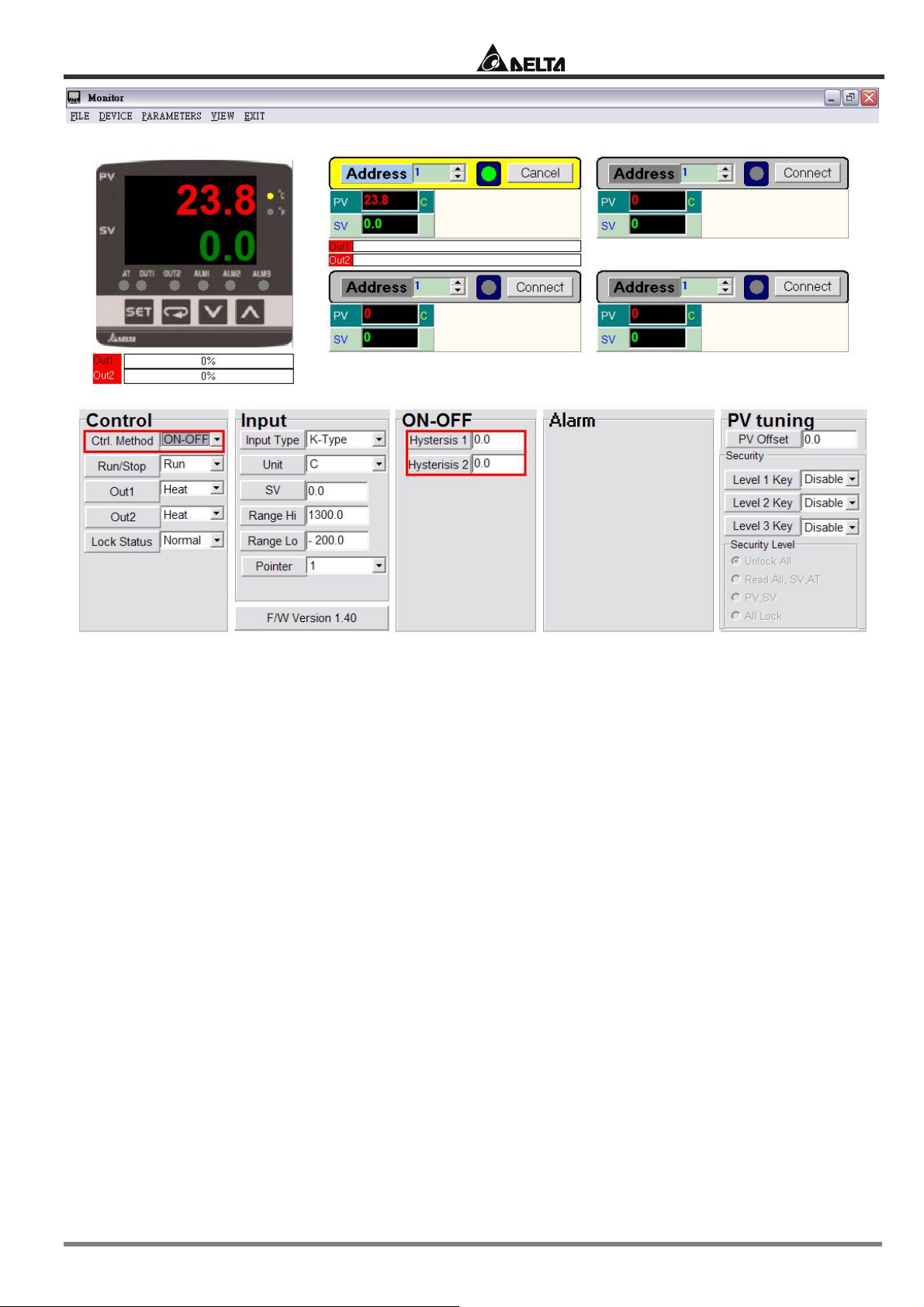
4.1 ON/OFF
There are four control modes in DTC: ON/OFF, MANUAL, PID and PID PROG. Due to that DTC has
no display panel, the settings and monitoring of parameters have to rely on communication.
Therefore, you have to check the following 2 items to ensure normal communication.
1. Make sure RS-485 hardware communication cable in DTC has been connected to the computer.
2. Make sure the communication parameters in DTC are consistent with those in the computer.
Next, open DTCOM Software and switch to ON/OFF control mode.
© DELTA ELECTRONICS, INC. ALL RIGHTS RESERVED - 21 - 2007-09-17
Page 22
Delta Temperature Controller User Manual
Set up hysteresis. Default = heating hysteresis. Can be set as cooling hysteresis as well. Both
default values are “0”.
2007-09-17 - 22 - © DELTA ELECTRONICS, INC. ALL RIGHTS RESERVED
Page 23
Delta Temperature Controller User Manual
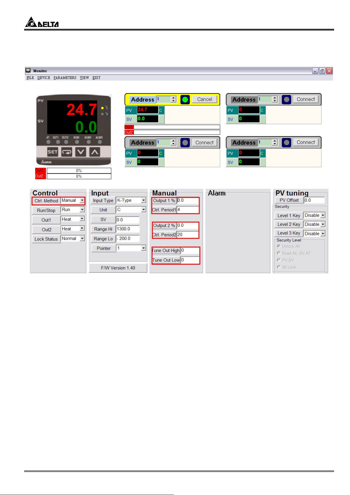
4.2 MANUAL
Switch the control mode to MANUAL mode.
Set up heating or cooling control cycle. Default = heating, 20 seconds per cycle.
Manually adjust the output percentage. Assume the percentage value = 50 and the cycle = 20
seconds plus heating control, the system will conduct heating output for 10 seconds and stop for
the other 10 seconds.
© DELTA ELECTRONICS, INC. ALL RIGHTS RESERVED - 23 - 2007-09-17
Page 24
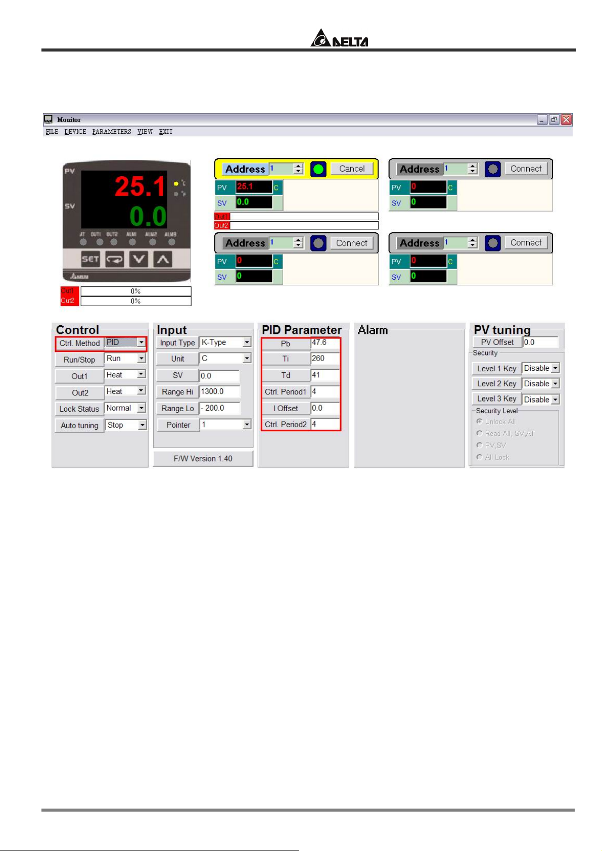
4.3 PID
Switch the control mode to PID mode
Delta Temperature Controller User Manual
You can conduct auto-tuning on the default PID parameters according to the environment where
your equipment is in or its temperature control capability, allowing the temperature controller to
generate relevant PID parameters by itself in order to achieve an accurate temperature control.
2007-09-17 - 24 - © DELTA ELECTRONICS, INC. ALL RIGHTS RESERVED
Page 25
Delta Temperature Controller User Manual
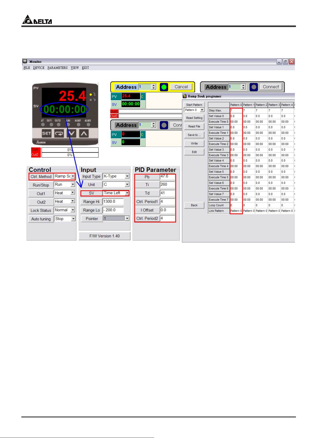
4.4 PID PROG
Switch the control mode to PID PROG mode
The 64 steps come from the combination of 8 patterns and 8 steps for each pattern. You can
establish maximum 64 steps according to different systems in use.
There are 8 steps in each pattern. You can define the step, loop and link pattern in each pattern.
© DELTA ELECTRONICS, INC. ALL RIGHTS RESERVED - 25 - 2007-09-17
 Loading...