

Page 1

Page 2

Preface
Thank you very much for purchasing DELTA’s DOP-A Series, DOP-AE Series and DOP-AS series Human
Machine Interface (hereinafter “HMI” ) products.
This manual will be helpful in the installation, operation and specifications of Delta HMI product and HMI
Screen Editor software program (hereinafter “ScrEdit” ). Before using the product, please read this user
manual to ensure correct use.
You should thoroughly understand all safety precautions (DANGERS, WARNINGS and STOPS) before
proceeding with the installation, wiring and operation. If you do not understand please contact your local
Delta sales representative. Place this user manual in a safe location for future reference.
Using This Manual
Contents of this manual
z This manual is a user guide that provides the information on how to install and operate
Delta HMI products and ScrEdit.
Who should use this manual
This user manual is intended for the following users:
z Those who are responsible for designing.
z Those who are responsible for installing or wiring.
z Those who are responsible for operating or programming.
Important precautions
Before using the product, please read this user manual thoroughly to ensure correct use and store
this manual in a safe and handy place for quick reference whenever necessary. Besides, please
observe the following precautions:
z Install the product in a clean and dry location free from corrosive and inflammable gases
or liquids.
z Ensure that HMI is correctly connected to a ground. The grounding method must comply
with the electrical standard of the country.
z Do not modify or remove wiring when power is applied to HMI.
z Before starting the operation, make sure the emergency stop equipment can be energized
and work at any time.
z Do not touch the power supply during operation. Otherwise, it may cause electric shock.
Revision Apr. 30th, 2007, 2007PDD23000002 i
Page 3

Preface|ScrEdit Software User Manual
This page intentionally left blank.
ii
Revision Apr. 30th, 2007, 2007PDD23000002
Page 4

Table of Contents
Preface........................................................................................................................................... i
Chapter 1 Introduction........................................................................................................... 1-1
1.1 DOP Series Human Machine Interface ...................................................................................... 1-1
1.2 Features ..................................................................................................................................... 1-1
1.3 Ordering Information................................................................................................................... 1-3
1.4 Caution ....................................................................................................................................... 1-4
Chapter 2 Creating and Editing Screens............................................................................... 2-1
2.1 ScrEdit (Screen Editor) Setup .................................................................................................... 2-1
2.2 How to Start ScrEdit ................................................................................................................... 2-5
2.3 Menu Bar and Toolbar (File) ...................................................................................................... 2-12
2.4 Menu Bar and Toolbar (Edit) ...................................................................................................... 2-23
2.5 Menu Bar and Toolbar (View) .................................................................................................... 2-31
2.6 Menu Bar and Toolbar (Element)............................................................................................... 2-43
2.7 Menu Bar and Toolbar (Screen)................................................................................................. 2-52
2.8 Menu Bar and Toolbar (Tools) ................................................................................................... 2-63
2.9 Menu Bar and Toolbar (Options)................................................................................................ 2-91
2.10 Menu Bar and Toolbar (Window) ............................................................................................... 2-122
2.11 Menu Bar and Toolbar (Help)..................................................................................................... 2-126
Chapter 3 Element Function ................................................................................................. 3-1
3.1 How to Choose Element............................................................................................................. 3-1
3.2 Button Element........................................................................................................................... 3-3
3.3 Meter Element ............................................................................................................................ 3-19
3.4 Bar Element................................................................................................................................ 3-21
Revision Apr. 30th, 2007, 2007PDD23000002
Page 5

Table of Contents|ScrEdit Software User Manual
3.5 Pipe Element .............................................................................................................................. 3-24
3.6 Pie Element ................................................................................................................................ 3-27
3.7 Indicator...................................................................................................................................... 3-29
3.8 Data Display ............................................................................................................................... 3-32
3.9 Graph Display............................................................................................................................. 3-38
3.10 Input Element ............................................................................................................................. 3-46
3.11 Curve Element............................................................................................................................ 3-52
3.12 Sampling Element ......................................................................................................................3-60
3.13 Alarm Element ............................................................................................................................ 3-68
3.14 Graphic Element......................................................................................................................... 3-73
3.15 Keypad Element ......................................................................................................................... 3-81
Chapter 4 Macro Function..................................................................................................... 4-1
4.1 Macro Type................................................................................................................................. 4-2
4.2 Macro Editing.............................................................................................................................. 4-7
4.3 Macro Operation......................................................................................................................... 4-14
4.4 Error Messages .......................................................................................................................... 4-42
Chapter 5 Control Block and Status Block ............................................................................ 5-1
5.1 Control Block .............................................................................................................................. 5-2
5.2 Status Block................................................................................................................................ 5-9
Chapter 6 Internal Memory ................................................................................................... 6-1
Chapter 7 Example Explanation............................................................................................ 7-1
Appendix A Specifications and Installation .............................................................................. A-1
A.1 Specifications ............................................................................................................................. A-1
A.2 Dimensions and Profile .............................................................................................................. A-5
A.3 Installation .................................................................................................................................. A-10
Revision Apr. 30th, 2007, 2007PDD23000002
Page 6

Table of Contents|ScrEdit Software User Manual
Appendix B USB Flash Drive Function .................................................................................... B-1
Appendix C Main Menu Operation of HMI System .................................................................. C-1
Revision Apr. 30th, 2007, 2007PDD23000002
Page 7

Table of Contents|ScrEdit Software User Manual
About this Manual…
User Information
Be sure to store this manual in a safe place.
Due to constantly growing product range, technical improvement and alteration or changed texts, figures and
diagrams, we reserve the right of this manual contained information change without prior notice.
Coping or reproducing any part of this manual, without written consent of Delta Electronics Inc. is prohibited.
Technical Support and Service
Welcome to contact us or visit our web site (http://www.delta.com.tw/industrialautomation/) if you need any
technical support, service and information, or, if you have any question in using the product. We are looking
forward to serve you needs and willing to offer our best support and service to you. Reach us by the
following ways.
ASIA
DELTA ELECTRONICS, INC.
TAOYUAN Plant/
31-1, SHIEN PAN ROAD, KUEI SAN
INDUSTRIAL ZONE TAOYUAN 333, TAIWAN
TEL: 886-3-362-6301
FAX: 886-3-362-7267
NORTH/SOUTH AMERICA
DELTA PRODUCTS CORPORATION
Sales Office/
P.O. BOX 12173
5101 DAVIS DRIVE,
RESEARCH TRIANGLE PARK, NC 27709, U.S.A.
JAPAN
DELTA ELECTRONICS (JAPAN) INC.
Sales Office/
DELTA SHIBADAIMON BLDG.
2-1-14 SHIBADAIMON, MINATO-KU,
TOKYO, 105-0012, JAPAN
TEL: 81-3-5733-1111
FAX: 81-3-5733-1211
EUROPE
DELTRONICS (NETHERLANDS) B.V.
Sales Office/
DE WITBOGT 15, 5652 AG EINDHOVEN,
THE NETHERLANDS
TEL: 31-40-259-2860
TEL: 1-919-767-3813
FAX: 1-919-767-3969
FAX: 31-40-259-2851
Revision Apr. 30th, 2007, 2007PDD23000002
Page 8

Chapter 1 Introduction
1.1 DOP Series Human Machine Interface
DOP series HMI are manufactured by adopting high-speed hardware to provide you with a powerful
programmable interface. ScrEdit software is a user-friendly program editor of DOP-A, DOP-AE and DOP-AS
series HMI for Windows. Please refer to the following section for its features and function introduction.
1.2 Features
PLC Serial Drives Support
DOP series HMI’s support more than twenty brands of PLC’s, including Delta, Omron, Siemens,
Mitsubishi, etc. All of the newly supported PLC’s communication protocol information could be found on
our website (http://www.delta.com.tw/industrialautomation/) for upgrade to meet your requirements. (All
other trademarks in this manual are property of their respective companies.)
Windows® Fonts Support for ScrEdit Software
Except Simplified Chinese, traditional Chinese and English languages, ScrEdit software also provides
those fonts that Windows® uses.
Quick Execution and Communication Macro
It can handle complicated calculation by executing macro. The user can also write communication
protocol with communication macro command to connect specific system via COM port.
Rapid USB Upload/Download
It will shorten upload/download time by using USB Ver1.1.
Recipes
It provides useful recipe editor that is similar to Microsoft excel for user to edit recipe easily and input
multiple recipes simultaneously (size limit is 64K). When downloading multiple recipes at the same time,
it can exchange by internal memory of HMI. If data has finished editing when downloading, you can
download recipe individually.
Direct Communication with Two or Three PLCs
DOP-A series HMI is able to connect to two different or the same controllers via two communication
ports. Up to three communication ports are provided in DOP-AE and DOP-AS series HMI for direction
connection to PLCs.
Revision Apr. 30th, 2007, 2007PDD23000002 1-1
Page 9

Chapter 1 Introduction|ScrEdit Software User Manual
Support Multiple PLC’s Connections
One DOP series HMI can connect to multiple controllers in serial through COM2 of RS-485 port
Simulation Function
HMI ScrEdit software provides simulation feature which allows the user to develop and debug software
on the PC connected to DOP series HMI before downloading it to DOP series HMI.
Off-line Simulation: When the editing and compile operation is completed, the user can use off-line
simulation function to simulate HMI operation and check if it is correct or not through the PC directly
without connecting to the controller.
On-line Simulation: When the editing and compile operation is completed, the user can use on-line
simulation function to simulate HMI operation and check if it is correct or not through the PC directly with
connecting to the controller.
(NOTE 2)
Using SM Card to Backup Data
SM card can also be used to backup data or transfer data to another HMI. After data transmission, the
data can be saved into the FLASH memory of HMI. History list and alarm message can be also saved in
SM card and the user can read these files by card reader for collecting data and printing.
(NOTE 1)
.
Multiple Security Protection
It provides passwords to protect designer’s intellectual property rights and also for the user to set the
user’s priority for important components. Only the user, whose priority is higher than the component, can
use the component.
USB Host Port (USB Host) Equipped
Parts of DOP series HMIs have a built-in USB Host interface for the connection to USB flash drive, card
reader and printer with USB socket. The user can save data, copy program and print the screen
immediately and increase the data storage space.
Multiple Security Protection
It provides passwords to protect designer’s intellectual property rights and also for user to set user
priority for important component.
Multi-Language Support
It is easy for the user to switch the desired language via HMI or the external controller. Furthermore,
Unicode editing is supported, and therefore it is convenient for the user to create and edit more quickly.
1-2 Revision Apr. 30th, 2007, 2007PDD23000002
Page 10

Chapter 1 Introduction|ScrEdit Software User Manual
NOTE
1) The controller should provide RS-485 interface.
2) Off-line/On-line simulation functions are only provided for some parts of the controllers. Also, the
execution time of on-line simulation only can continue 30 minutes. After the simulation time has
finished, HMI will return ScrEdit software main screen from simulation window automatically.
3) When executing simulation function, the resolution of PC screen should be set to 24bit and higher,
otherwise the simulation function may work abnormally.
1.3 Ordering Information
DOP – AE 10 TH T D – W
1 2 3 4 5 6 7
1. Product Name Delta Operation Panel
2. Series AS: USB Client, USB Host, COM Port x 3
A: USB Client, COM Port x 2
AE: USB Client, USB Host, COM Port x 3, Extension Port
3. Panel Size 38: 3.8 inches
57: 5.7 inches
75: 7.5 inches
80: 8 inches
94: 9.4 inches
10: 10.4 inches
4. Panel Color and Type BS: Blue/White 16 Grays STN
GS: Black/White 16 Grays FSTN
CS: 256 Colors STN
TC: 256 Colors TFT
TH: 65536 Colors TFT
5. Interface Type T: Touch Panel
6. Input Power D: DC +24V
7. Case Color None: Gray
W: White (currently be provided for AS38, A57 and AE57 models only)
Revision Apr. 30th, 2007, 2007PDD23000002 1-3
Page 11

Chapter 1 Introduction|ScrEdit Software User Manual
1.4 Caution
Operation Environment (temperature and humidity)
HMI should be operated in the following environment parameters to adjust screen brightness and
contrast to get the best image. If operating out of the range, LCD may be improperly displayed when
using for long time.
Ambient Operating Temperature: 0 ºC to 50 ºC (32 ºF to 122 ºF)
Relative Humidity: 10% ~ 90%, no condensation allowed
SM Card
SM card can be used to save and transmit data. Only SM card that formatted by HMI can be used on
both HMI and Windows® OS system. (Even it can be read/written in some format, but faults may occur
due to different format among Win95/98/2000/XP versions)
USB Flash Drive
USB flash drive can be used to save data. It also can be used to copy data from HMI and its format is
FAT32. When using USB flash drive to save data, we recommend the user should enter system screen
first and then remove the USB flash drive. Follow this process can ensure that the data is saved
completely in USB flash drive.
1-4 Revision Apr. 30th, 2007, 2007PDD23000002
Page 12
Chapter 2 Creating and Editing Screens
2.1 ScrEdit (Screen Editor) Setup
In this chapter, it will introduce general functions of Screen Editor with Windows. The user can use it to
design what he wants. Detail information for each function will be discussed in following chapters.
Minimum System Requirement
Below are the system requirements to comply with the operation environment of ScrEdit:
Item System Requirement
CPU Pentium III, 500MHz or greater is recommended
Memory 256MB and above is recommended
Hard Disk Capacity: 400MB and above
Monitor
Printer Printer compatible with Windows® 2000 & Windows® XP
Operation System Windows® 2000 & Windows® XP
Support resolution: 800 × 600 or higher full-color display.
Software installation
The user can download the Screen Editor, the program editor of Delta HMI product via the link below:
http://www.delta.com.tw/product/em/hmi/hmi_software.asp
To start the Delta HMI ScrEdit setup, please refer to the following steps:
1. Step 1: Please start-up your computer to Win2000/WinXP system (Fig. 2.1.1).
.
Fig. 2.1.1 Open Microsoft Windows
Revision Apr. 30th, 2007, 2007PDD23000002 2-1
Page 13
Chapter 2 Creating and Editing Screens|ScrEdit Software User Manual
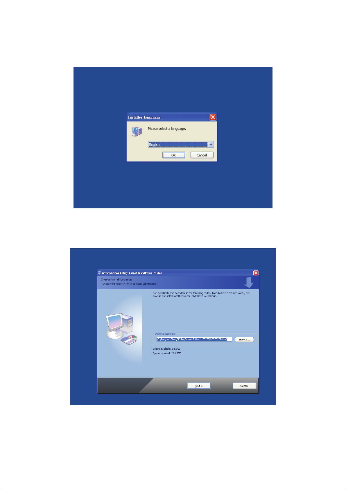
2. Step 2: Execute setup.exe from Windows taskbar by clicking “Start” > “Run”. 3. After pressing OK,
system will setup automatically and you will get the following dialog box to select the desired display
language (Fig. 2.1.2).
Fig. 2.1.2 Select Language
After pressing OK, system will setup automatically and you will get the following dialog box to choose
destination location (Fig. 2.1.3).
Fig. 2.1.3 Directory for installing ScrEdit
To select the default directory C: \Program File\Delta\Screen Editor 1.05.XX\, click Next> for the next
step. Setup will install in the directory indicated in the Destination Directory box at the bottom of the
dialog box.
2-2 Revision Apr. 30th, 2007, 2007PDD23000002
Page 14
Chapter 2 Creating and Editing Screens|ScrEdit Software User Manual
To select a directory other than the default directory, click Browse. A list of available directories appears.
Highlight the desired directory for the Delta HMI ScrEdit and click OK, then Next> for the next step.
If necessary, click < Back button to take you back through Setup dialog boxes one by one.
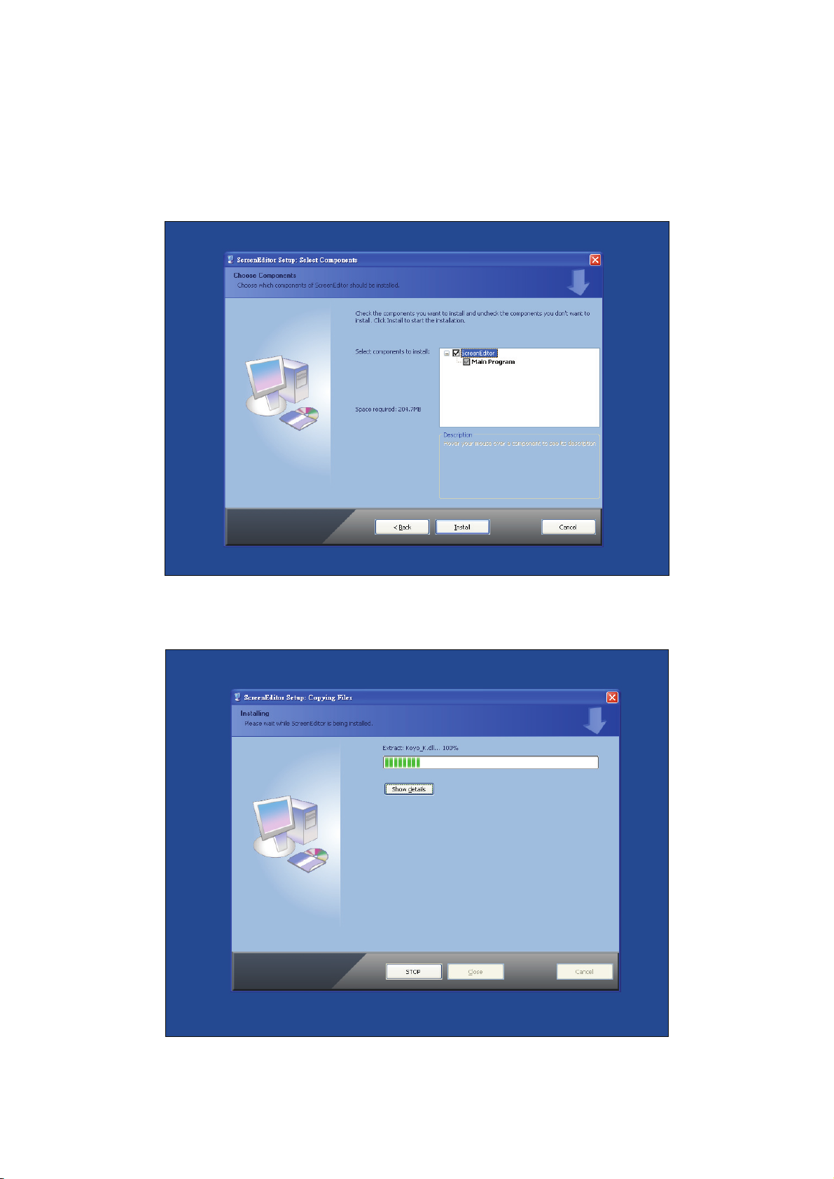
3. Step 3: After pressing Next, system will ask you to select the installation software, i.e. ScrEdit (Fig.
2.1.4).
Fig. 2.1.4 Select ScrEdit
4. Step 4: Then click Install button to start ScrEdit installation (Fig. 2.1.5).
Fig. 2.1.5 Starting ScrEdit installation
Revision Apr. 30th, 2007, 2007PDD23000002 2-3
Page 15
Chapter 2 Creating and Editing Screens|ScrEdit Software User Manual
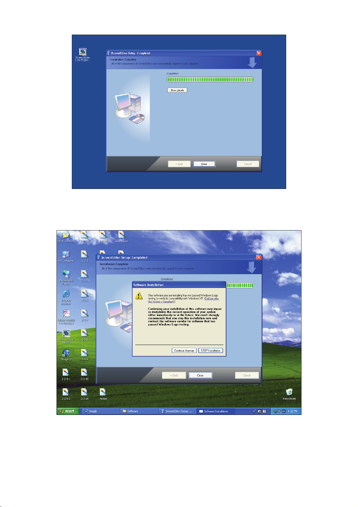
Fig. 2.1.6 Finish installing ScrEdit
5. Step 5: After finish installing ScrEdit (Fig. 2.1.6), system will ask you to install HMI USB driver, please
click Yes to install.
Fig. 2.1.7 Install HMI USB driver
6. Step 6: After installing HMI USB driver, click Close to complete the installation.
2-4 Revision Apr. 30th, 2007, 2007PDD23000002
Page 16

Chapter 2 Creating and Editing Screens|ScrEdit Software User Manual
2.2 How to Start ScrEdit
1. After setup, you can start ScrEdit by clicking Screen Editor 1.05.XX shortcut on the desk (Refer to Fig.
2.2.1) or from Windows taskbar, click Start > Programs > Delta > Screen Editor 1.05.XX.
Fig. 2.2.1
Fig. 2.2.2 Start-up display
Revision Apr. 30th, 2007, 2007PDD23000002 2-5
Page 17
Chapter 2 Creating and Editing Screens|ScrEdit Software User Manual
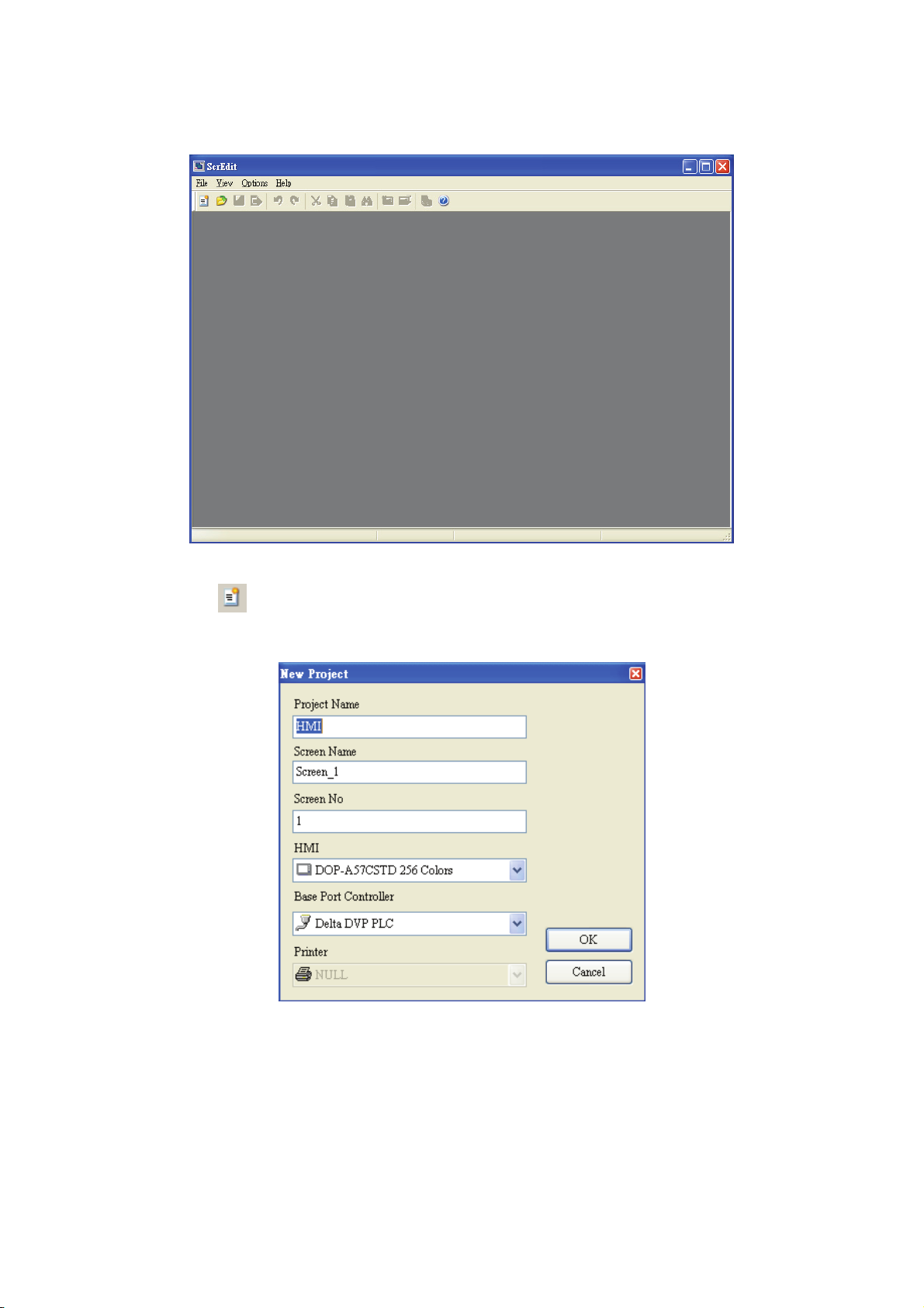
When ScrEdit is activated for the first time, the first window to show up is as follows. There are only File (F),
View(V), Option(O) and Help(H) on the toolbar.
2. After pressing
shown in the following. (Fig. 2.2.4)
or click File > New, it can create a new project and you will get a dialog box as
Fig. 2.2.3 Screen without editing file
Fig. 2.2.4 Creating a New project
3. Enter the Project Name, Screen Name, Screen No. and select connected HMI, controller or printer.
Then, click OK. It can create a new project in ScrEdit as shown in the following. (Fig. 2.2.5)
2-6 Revision Apr. 30th, 2007, 2007PDD23000002
Page 18
Chapter 2 Creating and Editing Screens|ScrEdit Software User Manual
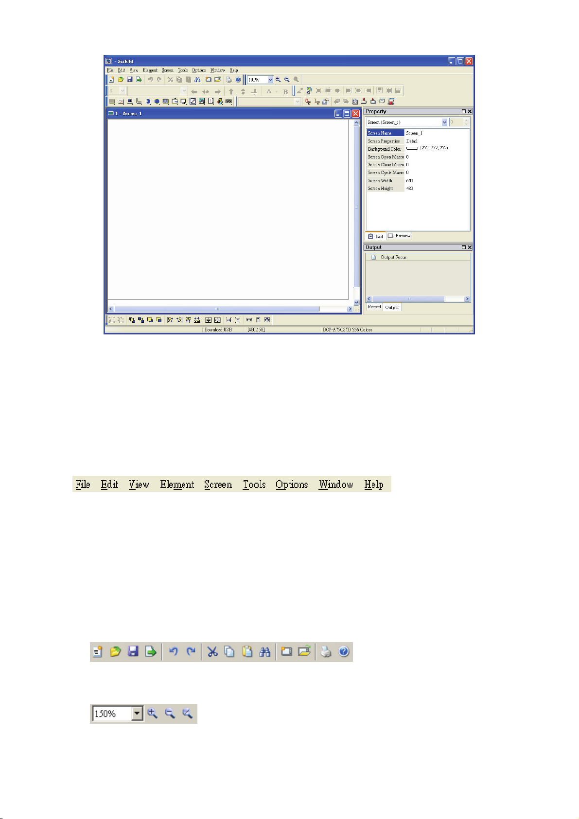
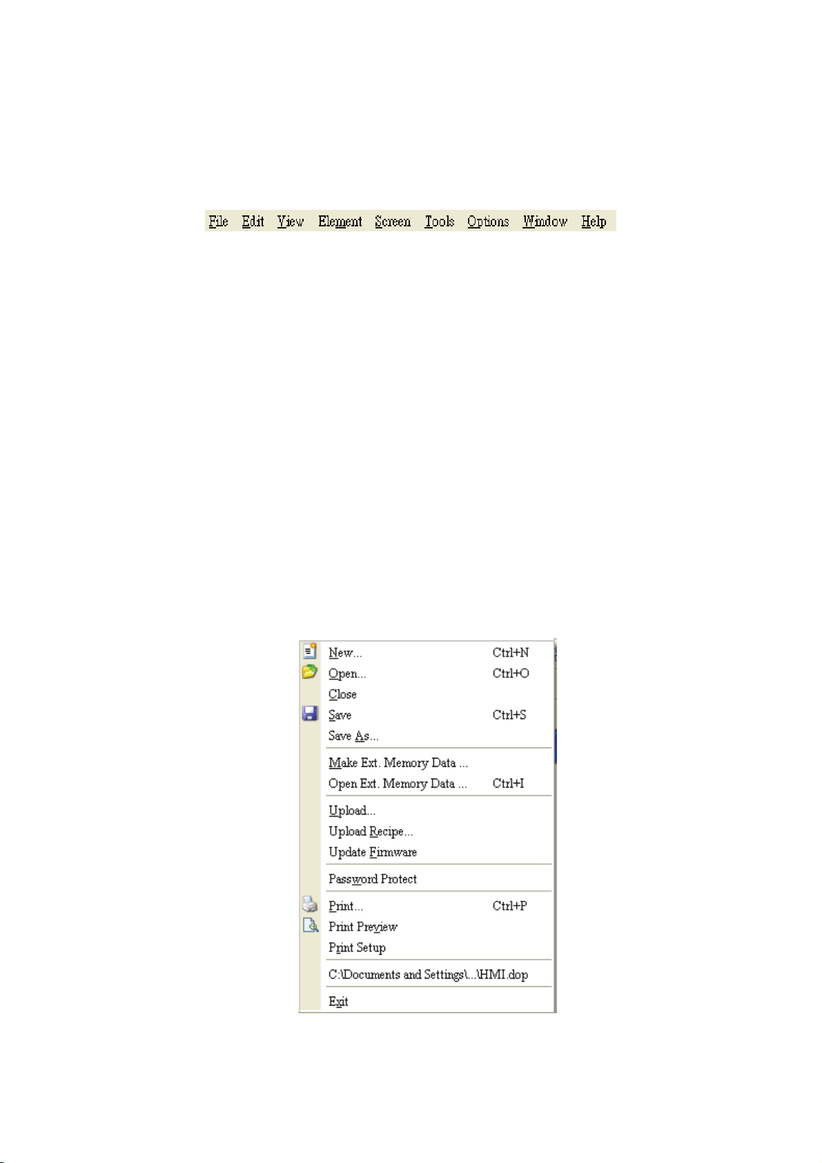
Fig. 2.2.5 New project screen of ScrEdit
There are five parts in the following for ScrEdit editing window.
Menu Bar
There are nine functions for selection: File, Edit, View, Element, Screen, Tools, Options, Window, and
Help.
Toolbar
Toolbar (Fig. 2.2.6) is like those toolbar in Windows® program. It is easy to use for editing and the user
can arrange its position freely. For example, the user can move the Toolbar to the left side of the screen.
Also, the user can arrange the toolbar position by their usage. The followings are the available toolbar on
ScrEdit.
1. Standard Toolbar
2. Zoom Toolbar
Revision Apr. 30th, 2007, 2007PDD23000002 2-7
Page 19
Chapter 2 Creating and Editing Screens|ScrEdit Software User Manual
3. Text Format Toolbar
4. Bitmap Toolbar
5. Element Toolbar
6. Build Toolbar
7. Layout Toolbar
Fig. 2.2.6 ScrEdit Toolbar
2-8 Revision Apr. 30th, 2007, 2007PDD23000002
Page 20
Chapter 2 Creating and Editing Screens|ScrEdit Software User Manual
Fig. 2.2.7 Move ScrEdit toolbar to the left side of the screen
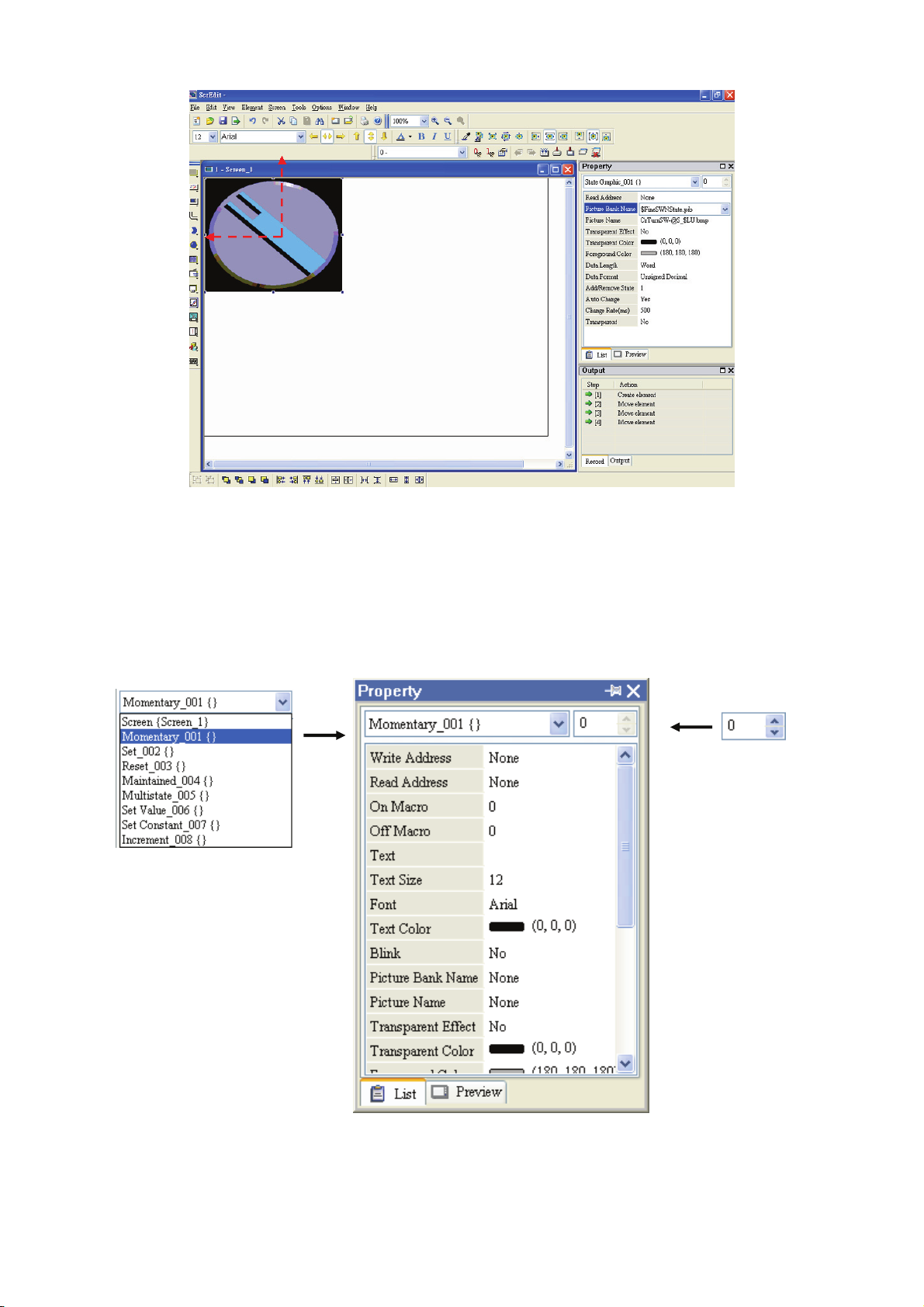
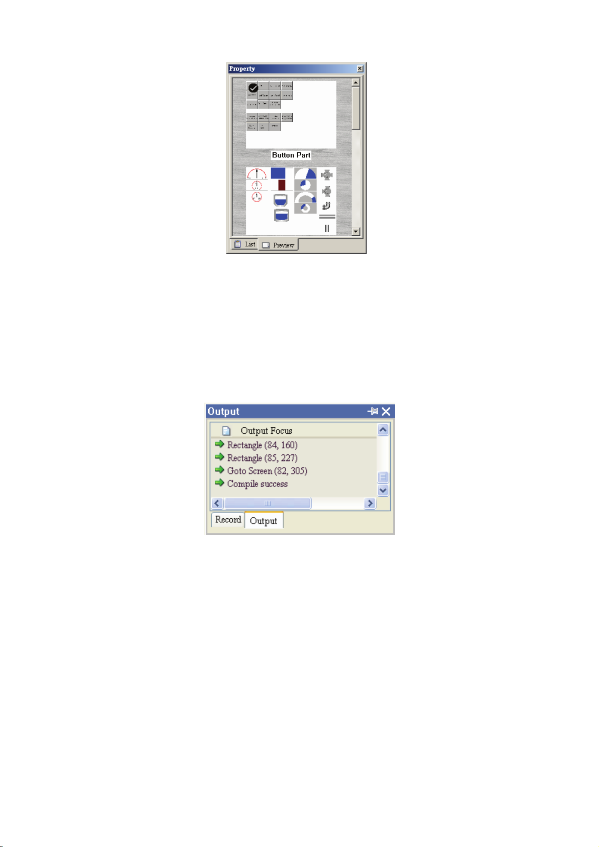
Property Table
It provides element property settings for each element (Fig. 2.2.8 & Fig. 2.2.9). Please refer to Chapter 3
for detailed description.
Element state selection
All elements on current
editing screen
Fig. 2.2.8 Property table
Revision Apr. 30th, 2007, 2007PDD23000002 2-9
Page 21
Chapter 2 Creating and Editing Screens|ScrEdit Software User Manual
Fig. 2.2.9 Editing screen preview
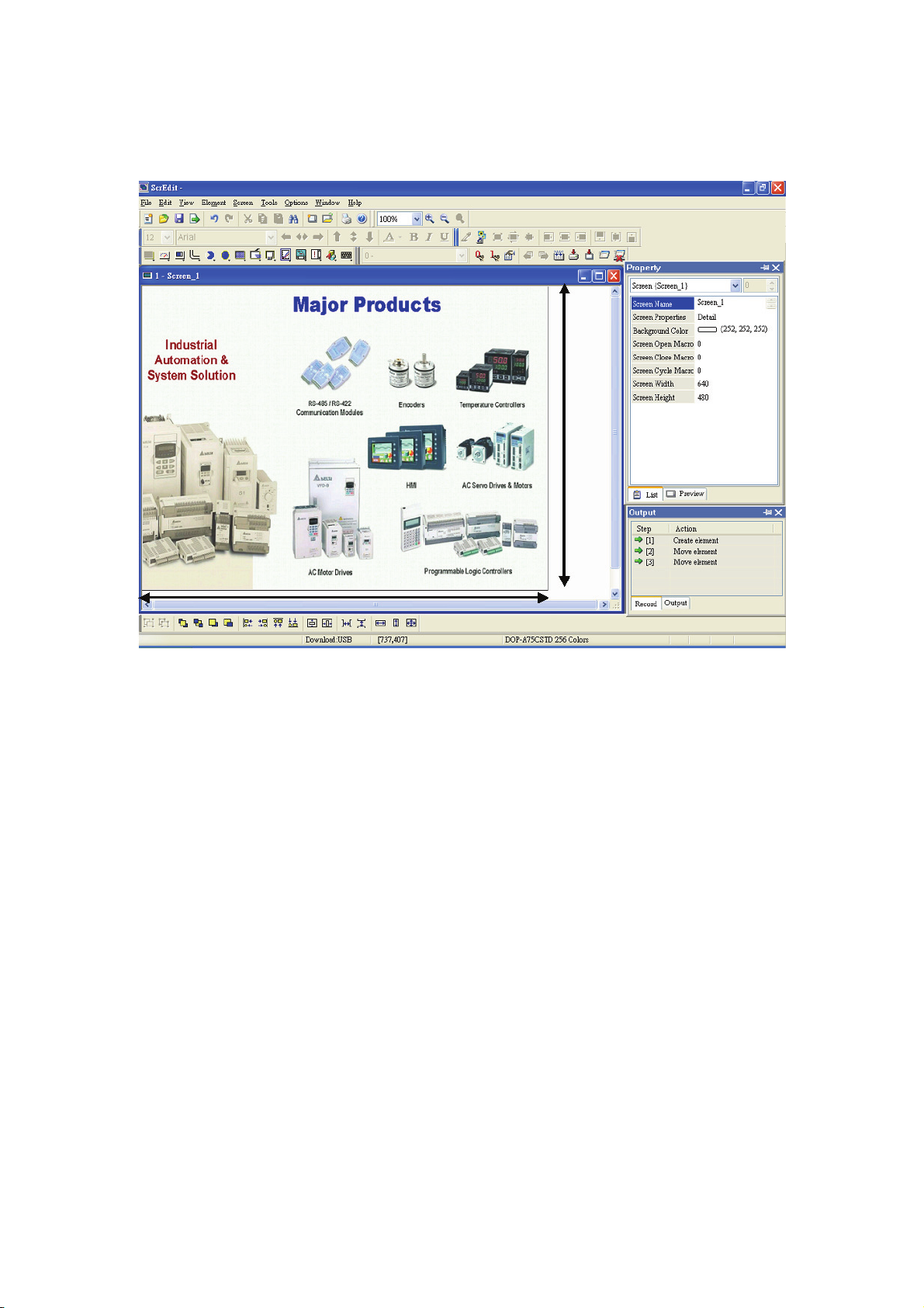
Output Window
All editing actions and output message when compile function is enabled will be shown here (Fig. 2.2.10).
When compiling, ScrEdit will detect the error of user program automatically. Once error occurs, the
correspondent message will display in output window. Click error message to get error element window.
Fig. 2.2.10 Output window
2-10 Revision Apr. 30th, 2007, 2007PDD23000002
Page 22
Chapter 2 Creating and Editing Screens|ScrEdit Software User Manual
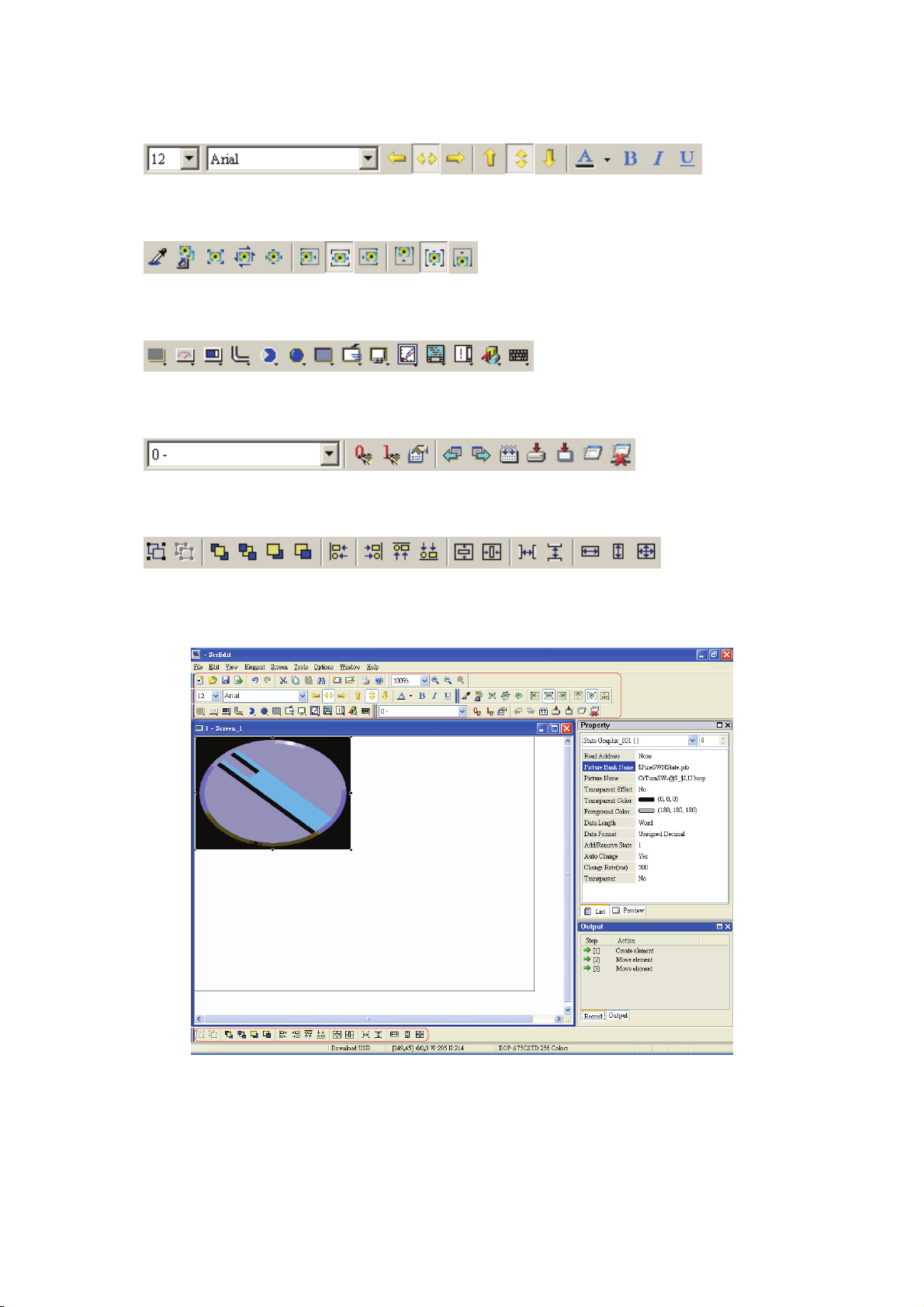
Work Place
Following is an editing example display (Fig. 2.2.11).
Fig. 2.2.11 ScrEdit Work Place
Revision Apr. 30th, 2007, 2007PDD23000002 2-11
Page 23
Chapter 2 Creating and Editing Screens|ScrEdit Software User Manual
2.3 Menu Bar and Toolbar (File)
ScrEdit provides the convenient pull-down Menu and makes it easy for the user to create, edit and manage
includes elements, pictures, graphs, macro program, recipes and displays in DOP series HMI. The pull-down
menu options of Menu bar are described as follows:
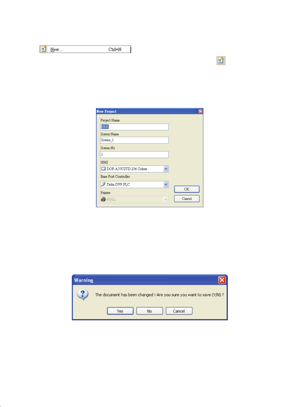
File
The “File” menu performs many common functions.
1. Allows user to create new project, open old project, close file, save current file and save current file
to another file name, etc. options.
2. Make and Open external memory data (Ext. Memory Data).
3. Upload the editing display and data of DOP series HMI to PC and save to hard disk.
4. Update the firmware of DOP series HMI.
5. Password protection function.
6. Screen print, print preview and print setup functions.
7. By default, ScrEdit presents a list of the most recent used files on the File menu for quick access.
Just click the file name to open the file.
8. Exit command is to close all open editing files and offer to save those which have not been save
yet and finally exit the ScrEdit.
Fig. 2.3.1 File options
2-12 Revision Apr. 30th, 2007, 2007PDD23000002
Page 24
Chapter 2 Creating and Editing Screens|ScrEdit Software User Manual
Create a New Project
Creates a new project by choosing File > New (Fig. 2.3.2) or clicking the New icon
(Fig. 2.3.3), or using keyboard shortcuts by pressing Ctrl + N.
1. If this is the first time use and there is no old project, the following dialog box (Fig. 2.3.2) will show
up for the user to input project name, screen name, screen number, HMI type and connecting
base port controller after creating a new project.
from toolbar
Fig. 2.3.2 New project dialog box
2. If other project files already exist and are open, the user will get the following dialog box to remind
the user of saving project (Fig. 2.3.3) before creating new project. Press Yes button to save the
existed file, press No button not to save the file and press Cancel button to cancel the save
operation. After the user press the Yes or No button, the new project dialog box will appear again
(Fig. 2.3.2).
Fig. 2.3.3 Saving dialog box
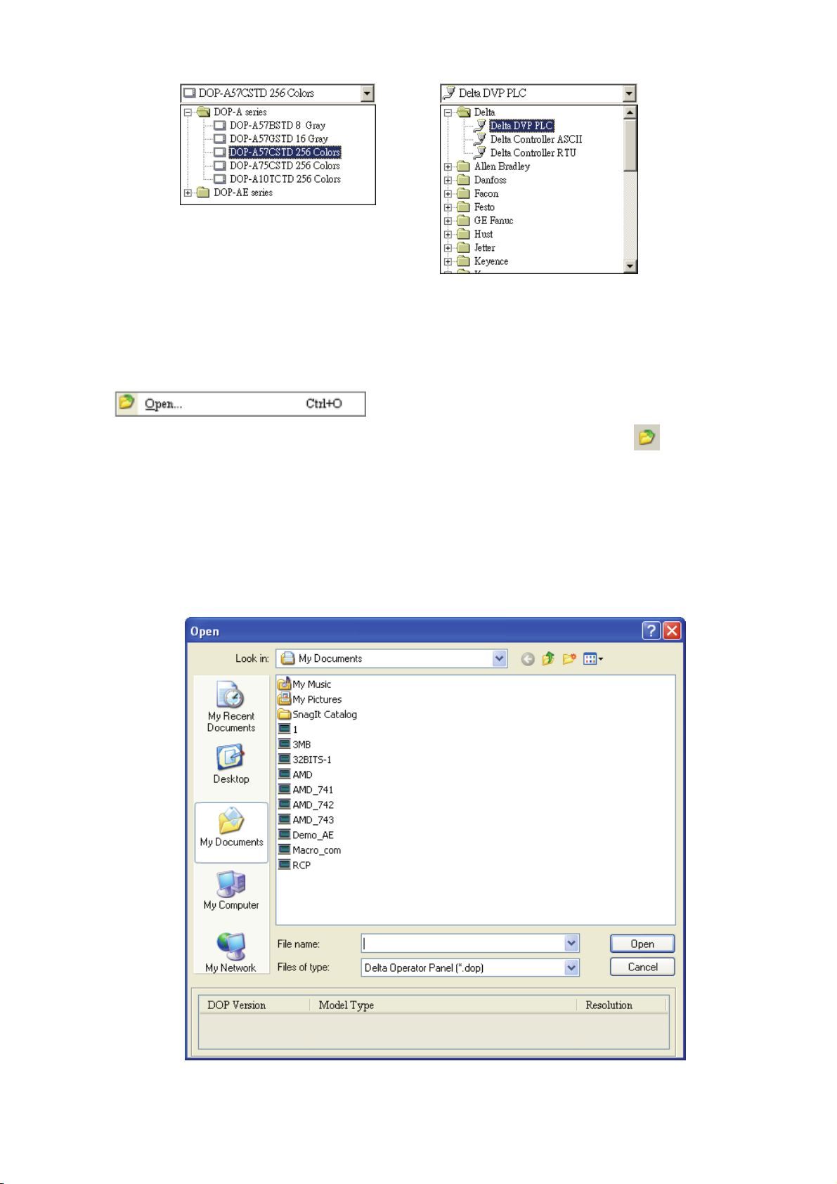
3. Input project name, screen name, select HMI model and connecting base port controller (Fig.
2.3.4), and then press OK button.
Revision Apr. 30th, 2007, 2007PDD23000002 2-13
Page 25
Chapter 2 Creating and Editing Screens|ScrEdit Software User Manual
Fig. 2.3.4 HMI model and base port controller options
Open Old Project
Open current project by choosing File > Open (Fig. 2.3.7) or clicking the Open icon
or using keyboard shortcuts by pressing Ctrl + O.
1. If other project files exist before opening an old project, the user will get the Saving dialog box (Fig.
2.3.3) to remind the user of saving file and then get the following dialog box for opening existing
dop file (Fig. 2.3.5).
2. If save operation is complete or there is no old project files, the following dialog box for opening
existing dop file (Fig. 2.3.5) will show up directly.
from toolbar,
Fig. 2.3.5 Open an old project in ScrEdit
2-14 Revision Apr. 30th, 2007, 2007PDD23000002
Page 26
Chapter 2 Creating and Editing Screens|ScrEdit Software User Manual
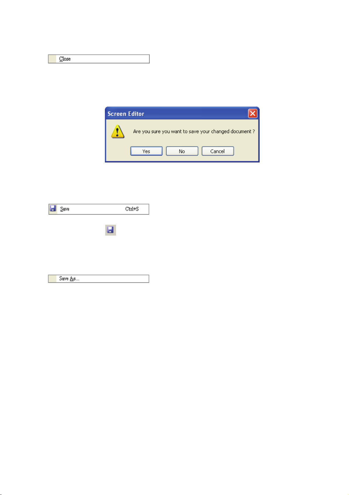
Close File
Closes project by clicking File > Close (Fig. 2.3.10).
1. If project didn’t get saved before issuing the command of closing project, the user will get saving
dialog box (Fig. 2.3.6) to remind the user of saving project.
Fig. 2.3.6 Saving dialog box
Save File
Save current project into hard disk with extension file “dop” by choosing File > Save (Fig. 2.3.12) or
clicking the Save icon
is a new file, the Save as dialog box will show up (Fig. 2.3.15). If the project is an old file, the Save
function will perform immediately and the Save as dialog box will not show up.
Save As
(Fig. 2.3.13), or using keyboard shortcuts by pressing Ctrl + S. If the project
Save current project to another file name by clicking File > Save As (Fig. 2.3.14). The user will get
Save as dialog box (Fig. 2.3.15) to input project name with extension file dop. This dialog also appears
automatically when the first time any project file is saved no matter whether Save As or Save command
is used.
Revision Apr. 30th, 2007, 2007PDD23000002 2-15
Page 27
Chapter 2 Creating and Editing Screens|ScrEdit Software User Manual
Fig. 2.3.7 Save as dialog box (Dialog box that let user input project name to save as.)
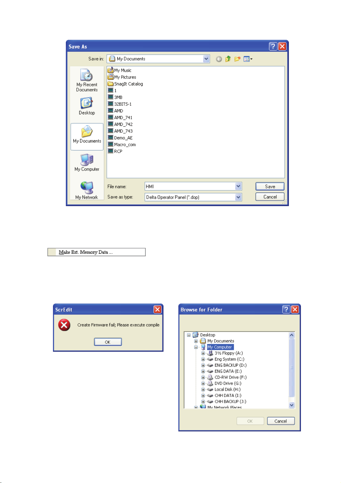
Make Ext. Memory Data
Before using this command, ensure to compile the editing screen data. If not execute the compilation
first, the ScrEdit cannot make screen data and an error message dialog box will show up (Fig. 2.3.8).
Please execute the compilation first and then clicking File > Make Ext. Memory Data to copy the
compiled HMI program into SM card (Fig. 2.3.9) or a USB flash drive. If the SM card or USB flash drive
with compiled HMI program stored inside is inserted into HMI, HMI will startup by reading the data of
SM card or USB flash drive directly.
Fig. 2.3.8 Error message dialog box when
making Ext. Memory Data
Fig. 2.3.9 Make Ext. Memory Data Dialog Box
2-16 Revision Apr. 30th, 2007, 2007PDD23000002
Page 28
Chapter 2 Creating and Editing Screens|ScrEdit Software User Manual
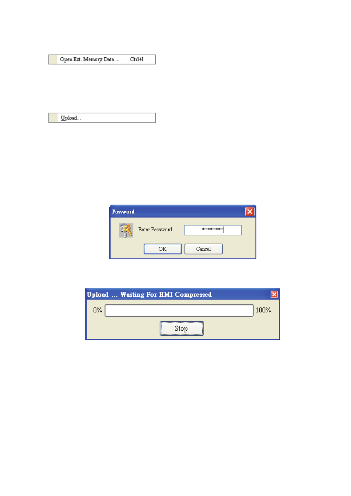
Open Ext. Memory Data
In HMI, the user can move the screen data saved in the flash memory into SM card through folder
manager. Then, perform Open Ext. Memory Data function and the user will get the user will get Fig.
2.3.9 dialog box. At this time, the user can open the screen data and edit the HMI screen data directly.
Upload
After clicking File > Upload, the password dialog box will show up first (Fig. 2.3.10), the user needs to
input password (the password is the highest priority saved in HMI, which is set by clicking Options >
Configuration > Standard > Security). When entering the correct password, the user can get save as
dialog box (Fig. 2.3.7). After inputting project file name, the uploading will start (Fig. 2.3.11). The user
can get the progress with progress box and stop uploading by clicking Stop button. When progress
goes to 100%, it indicates that the uploading is complete. The user can press Stop button to exit the
dialog box. The file that is uploaded from HMI can be restored to original editing file for user to edit.
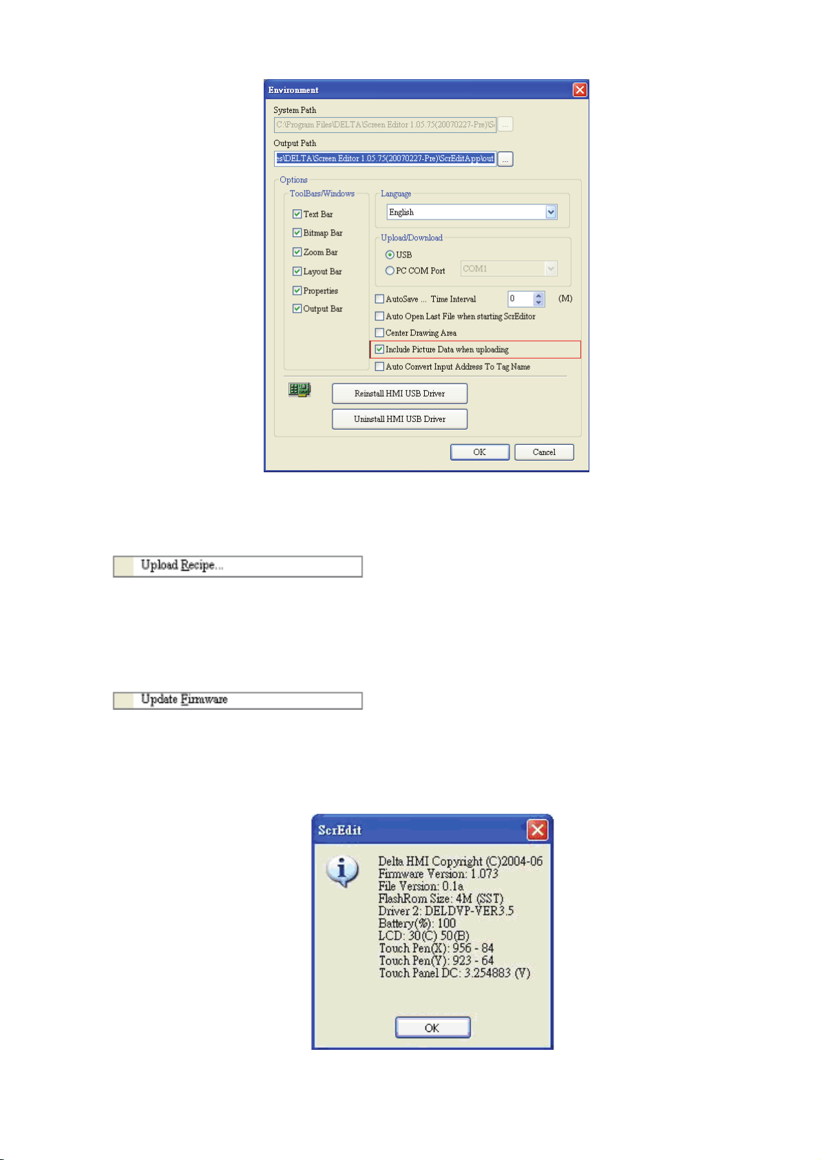
This option is to avoid losing the original editing file. If the user wants to upload data with pictures also,
just select the “Include Picture Data when uploading” in Environment dialog box by clicking Options >
Environment.
Screen Data and Recipe
Fig. 2.3.10 Enter password dialog box
Fig. 2.3.11 Uploading screen
Revision Apr. 30th, 2007, 2007PDD23000002 2-17
Page 29
Chapter 2 Creating and Editing Screens|ScrEdit Software User Manual
Fig. 2.3.12 Environment dialog box
Upload Recipe
This function is similar to upload function but it can only upload recipe. Before uploading, it also needs
to enter password (the password is the highest priority saved in HMI, which is set by clicking Options >
Configuration > Standard > Security).
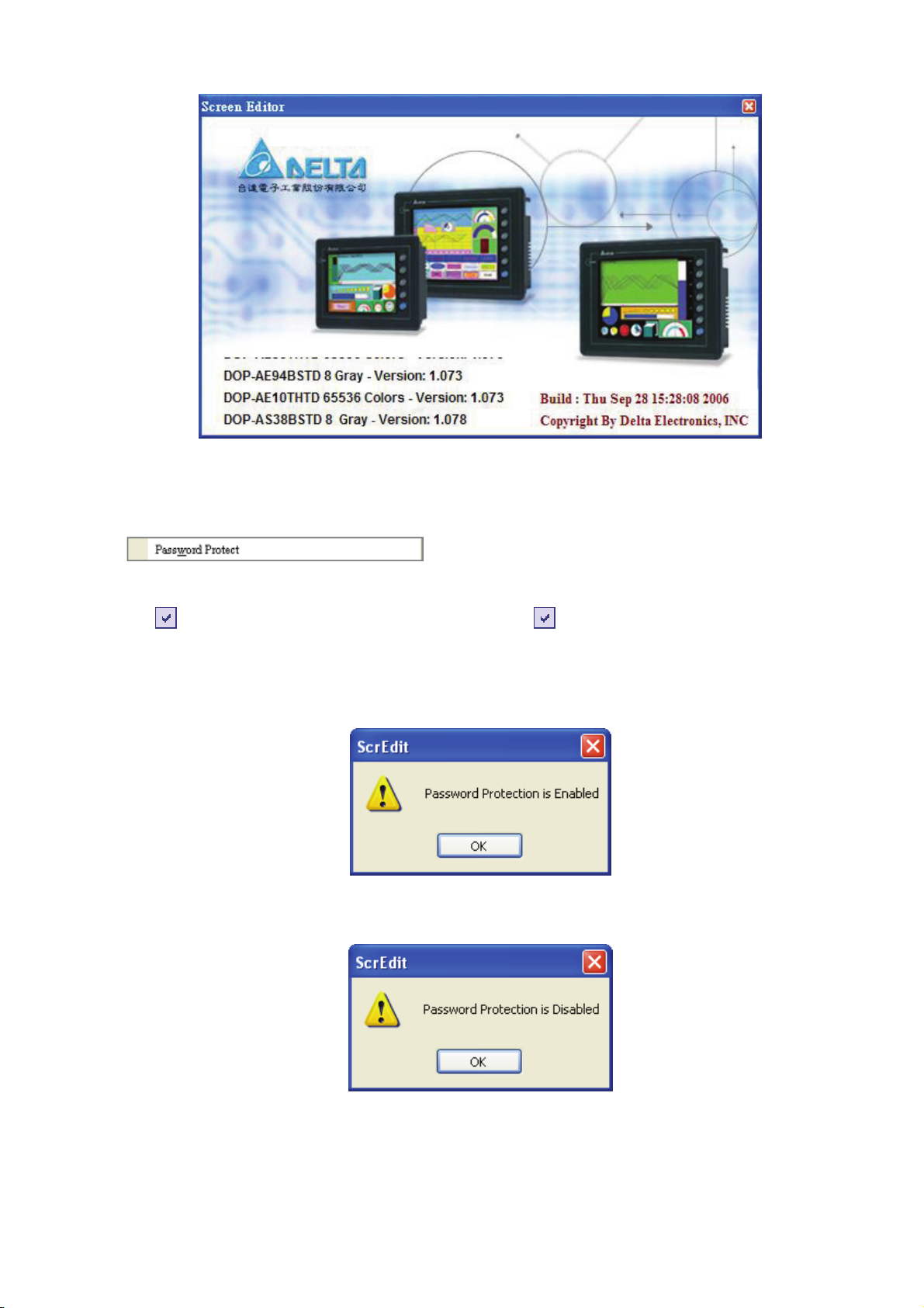
Update Firmware
This option is for upgrading HMI firmware or adding function for HMI (Fig. 2.3.13). Keeping HMI
firmware version to be the most updated version can optimize HMI operation. Ensure that the software
version of ScrEdit matches the firmware version. The user can get the firmware information by clicking
Tools > Get Firmware Information. Regarding the software version of ScrEdit, the user can find it by
clicking Help > About ScrEdit (Fig. 2.3.14).
Fig. 2.3.13 Choosing Update Firmware command from menu bar
2-18 Revision Apr. 30th, 2007, 2007PDD23000002
Page 30
Password Protect
Chapter 2 Creating and Editing Screens|ScrEdit Software User Manual
Fig. 2.3.14 About ScrEdit
The user can enable and disable password protect function (Fig. 2.3.15 & Fig. 2.3.16) by clicking File >
Password protect. Once password protect function is enabled, the user will get Fig. 2.3.15 dialog box
and
Protect” command from File menu, it indicates that this dop file is password protected and the user will
need to input password before opening dop file. The password is set by clicking Options >
Configuration > Standard > Security) (Fig. 2.3.17). If the password protect function is disabled, the
Fig. 2.3.16 dialog box will show up.
symbol before “Password Protect” command. If the symbol shows before “Password
Fig. 2.3.15 Password protect function is enabled
Fig. 2.3.16 Password protect function is disabled
Revision Apr. 30th, 2007, 2007PDD23000002 2-19
Page 31

Chapter 2 Creating and Editing Screens|ScrEdit Software User Manual
Fig. 2.3.17 Password settings - Security
Print
Print current screen by choosing File > Print, or clicking the Print icon
using keyboard shortcuts by pressing Ctrl + P.
Print Preview
Select this function by clicking File > Print Preview. Using this function can preview the full page after
printing (Fig. 2.3.18).
from toolbar (Fig. 2.3.28), or
Fig. 2.3.18 Print Preview screen
2-20 Revision Apr. 30th, 2007, 2007PDD23000002
Page 32
Chapter 2 Creating and Editing Screens|ScrEdit Software User Manual
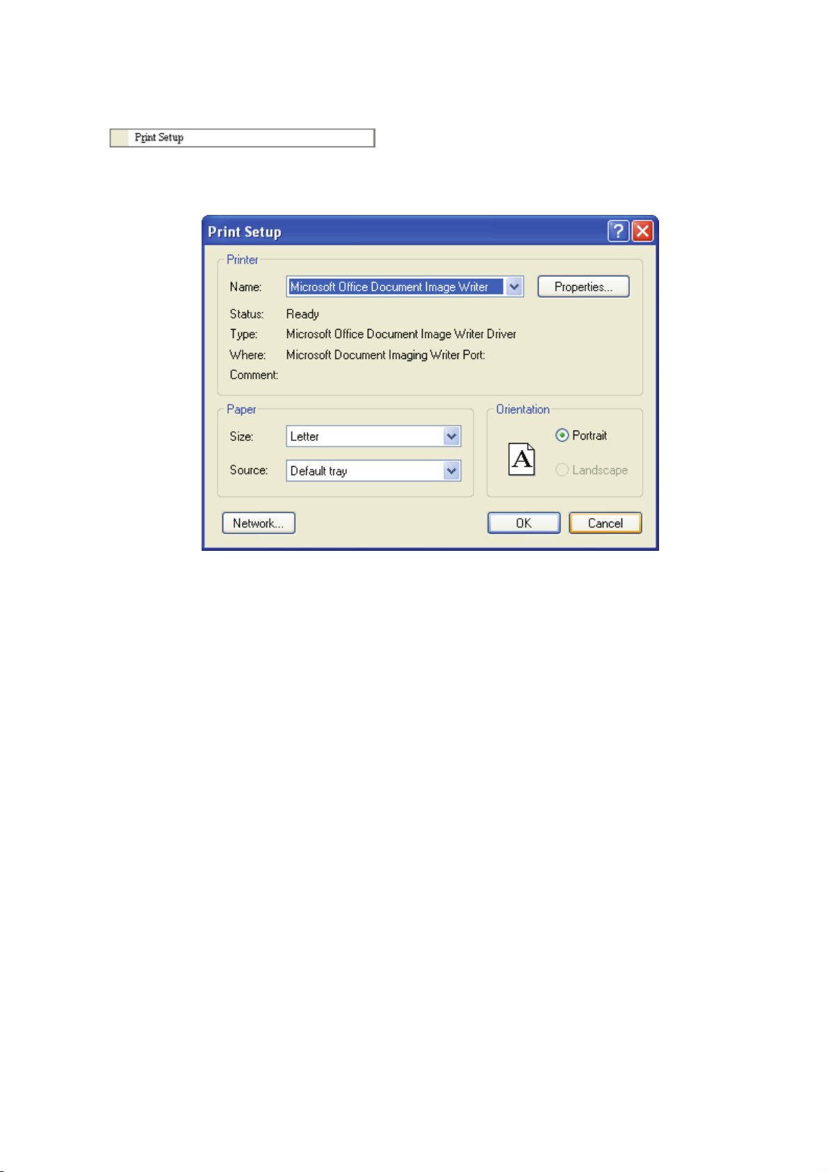
Print Setup
Printer and paper settings. Select this function by clicking File > Print Setup. Using this function can set
the property of printer, print paper and print direction, etc. several functions (Fig. 2.3.19).
Fig. 2.3.19 Print Setup dialog box
File Quick Access
By default, ScrEdit presents a list of the four most recent used files on the File menu for quick
access (Fig. 2.3.20). Just click the file name to open the file. This function is similar to the Open
command and the user can refer to the description of Open command on the page 2-14. If the
saving path is too long, the too long path will display as “….”. The user still can see the complete
dop file name.
Revision Apr. 30th, 2007, 2007PDD23000002 2-21
Page 33

Chapter 2 Creating and Editing Screens|ScrEdit Software User Manual
Fig. 2.3.20 Most recent used files
Exit
Exit function is to close all open editing files and offer to save those that have not been save yet and
finally exit the ScrEdit. Select this function by clicking File > Exit. If the file has been changed or not
saved yet, the saving dialog box (Fig. 2.3.6) will show up to remind the user of saving project. If the
user press Cancel button at this time, the exit command is cancelled. Either pressing Yes button to
save the file, or pressing No button not to save the file can exit the ScrEdit. After the user press the
Yes button, the Save As dialog box will appear (Fig. 2.3.7) for saving the file.
2-22 Revision Apr. 30th, 2007, 2007PDD23000002
Page 34

Chapter 2 Creating and Editing Screens|ScrEdit Software User Manual
2.4 Menu Bar and Toolbar (Edit)
Edit
Adopt pull-down menu similar to Microsoft Office style and provide user-friendly Edit pull-down menu (Fig.
2.4.1).
Fig. 2.4.1 Edit options
Undo
Undo the last action. Select this function by choosing Edit > Undo or clicking the Undo icon
toolbar, or use keyboard shortcuts by pressing Ctrl + Z. All actions are recorded in output window.
Redo
Redo the undo action. Select this function by choosing Edit > Redo or clicking the Redo icon from
toolbar, or use keyboard shortcuts by pressing Ctrl + Y. All actions are recorded in output window.
Cut
Deletes the selected element and save it in clipboard to paste to other place. Select this function by
from
choosing Edit > Cut from menu bar or clicking the Cut icon
shortcuts by pressing Ctrl + X.
Revision Apr. 30th, 2007, 2007PDD23000002 2-23
from toolbar, or use keyboard
Page 35
Chapter 2 Creating and Editing Screens|ScrEdit Software User Manual
Copy
Copy the selected element to the clipboard. Select this function by choosing Edit > Copy from menu
bar or clicking the Copy icon
Paste
Paste element from clipboard. Select this function by choosing Edit > Paste from menu bar or clicking
the Paste icon
Delete
Delete selected element. Select this function by choosing Edit > Delete from menu bar or use
keyboard shortcuts by pressing Del.
Select All
It is used to select all elements. Select this function by choosing Edit > Select All from menu bar or
use keyboard shortcuts by pressing Ctrl + A. When selecting all, the last created element, i.e. the
picture on the top will be a square that is filled with blue color and the border is in white. The other
created elements will be in white color and the border is in black. This is to provide a reference for Align
and Make Same Size function. When there are two and more elements, one element should be the
base element
from toolbar, or use keyboard shortcuts by pressing Ctrl + V.
. The base element is used to align or resize.
from toolbar, or use keyboard shortcuts by pressing Ctrl + C.
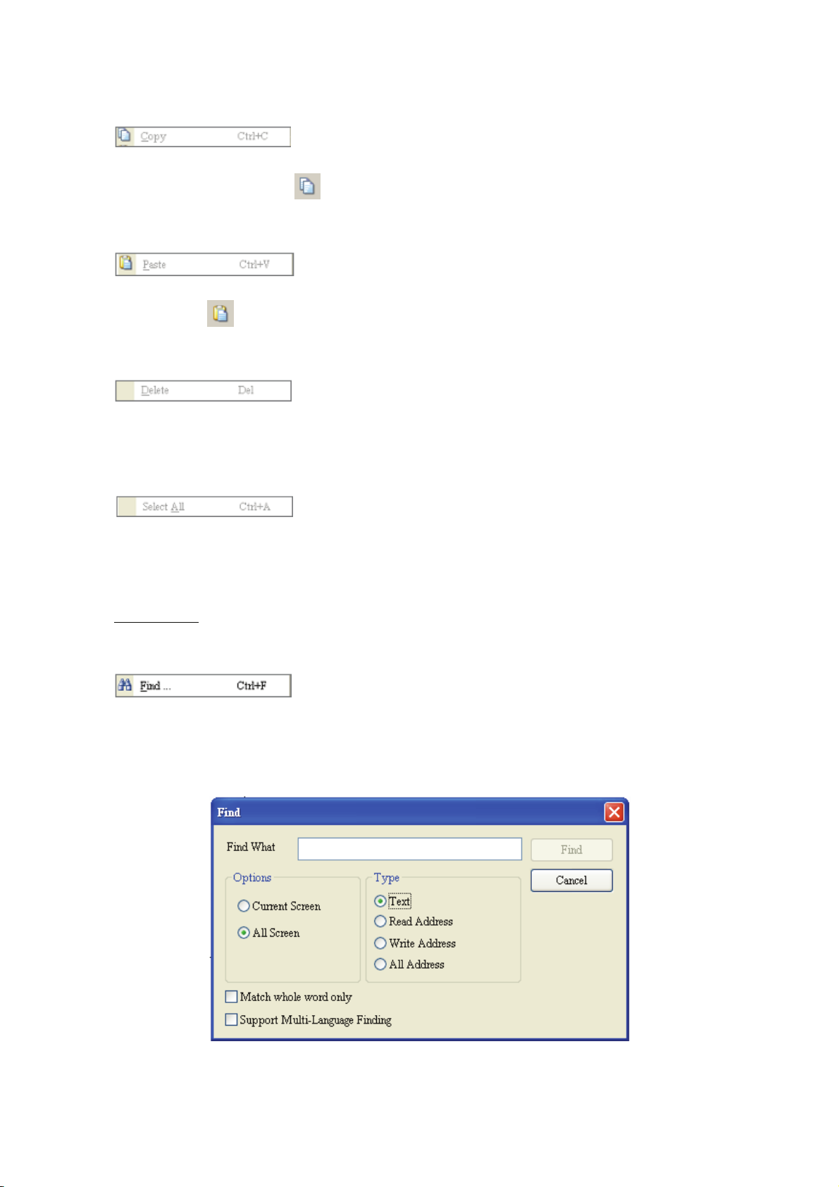
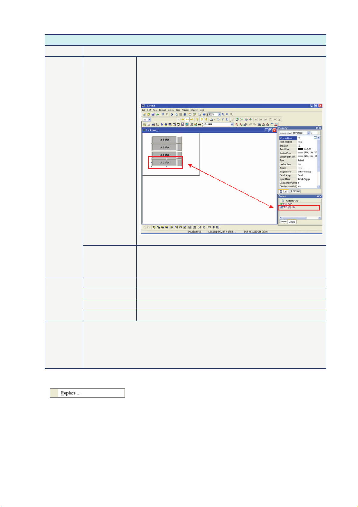
Find
It is used to find the content matches the find criteria. Select this function by choosing Edit > Find from
menu bar or use keyboard shortcuts by pressing Ctrl + F. The user can find element text, read
address, write address or memory address in current screen, or all screens (Fig. 2.4.2). Once it finds,
the result of find content will be shown in the output window. Click some of the result of find content, it
will jump to its location in ScrEdit (Fig. 2.4.3).
Fig. 2.4.2 Find option
2-24 Revision Apr. 30th, 2007, 2007PDD23000002
Page 36
Chapter 2 Creating and Editing Screens|ScrEdit Software User Manual
Find
Find What This field is where the user enters the word or phase that the user is looking for
Options
Current Screen This causes ScrEdit to navigate the current screen only and find the
matching word or phase that the user is looking for. The output
window will display all matching words or phases. When the user
double clicks the word or phase, ScrEdit will jump to that location of
the matching word or phase. Please refer to the example screen
below.
Fig. 2.4.3
All Screen This causes ScrEdit to navigate all screens and find the word or phase
that the user is looking for. The output window will display all matching
words or phases. When the user double clicks the word or phase,
ScrEdit will also jump to that location of the matching word or phase.
Type
Text This causes ScrEdit to find the text.
Read Address This causes ScrEdit to find the read address.
Write Address This causes ScrEdit to find the write address.
All Address This causes ScrEdit to find the read and write address.
Check Box If “Match whole word only” box is checked, only the exact word or phase that the user
types will be found. If “Match whole word only” box is not checked, all words that contain
the word or phase that the user types will be found.
If “Support Multi-Language Finding” box is checked, all multi language words that contain
the word or phase that the user types will be found. However, “Support Multi-Language
Finding” option can only be enabled when the find content type is text.
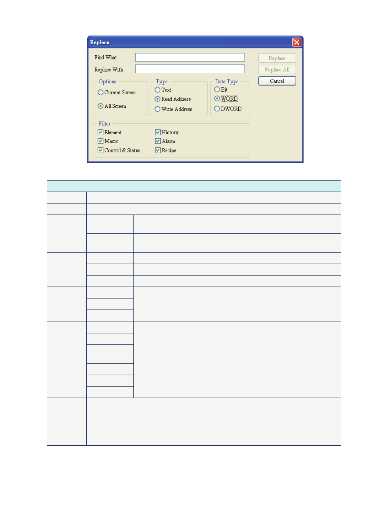
Replace
It is used to replace the content (Fig. 2.4.4). Using this command can replace text, read address and
write address in current screen or all screens. Its function is very similar to Find command expect that it
not only can find the word or phase that the user is looking for but also can replace it with a new entry.
The replace content type could be text, read and write address and the replace content data type could
be Bit, Word or Double Word. The function of replace content data type is enabled only when the
replace content type is either read or write address. Select this function by choosing Edit > Replace
from menu bar or use keyboard shortcuts by pressing Ctrl + R.
Revision Apr. 30th, 2007, 2007PDD23000002 2-25
Page 37
Chapter 2 Creating and Editing Screens|ScrEdit Software User Manual
Fig. 2.4.4 Replace option
Replace
Find What This field is where the user enters the word or phase that the user is looking for
Replace With This field is where the user enters the word or phase that the user wants to replace with
Options
Type
Data Type
Filter
Current Screen This causes ScrEdit to navigate the current screen only, find the matching
word or phase that the user is looking for and replace it.
All Screen This causes ScrEdit to navigate all screens and find the matching word or
phase that the user is looking for and replace it.
Text This causes ScrEdit to find and replace the text.
Read Address This causes ScrEdit to find and replace the read address.
Write Address This causes ScrEdit to find and replace the write address.
Bit
WORD
DWORD
Element
Macro
Control &
Status
History
Alarm
The function of replace content data type is enabled only when the
replace content type is either read or write address. The replace content
data type could be Bit, Word or Double Word.
This option is available when the replace content is read and write
address. There are six options for selection, Element, Macro, Control &
Status, History, Alarm and Recipe.
Recipe
Replace
Replace All
2-26 Revision Apr. 30th, 2007, 2007PDD23000002
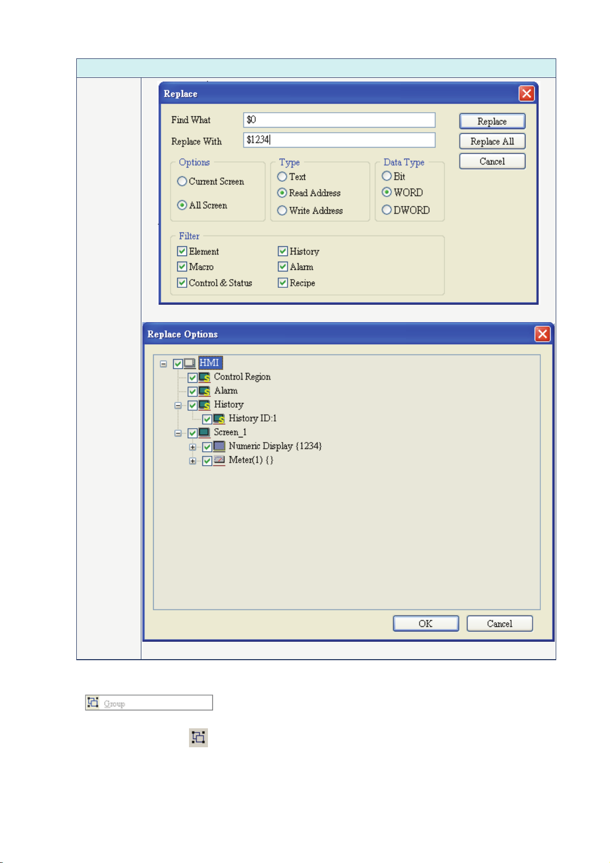
Replace button is used to replace the word or phase that the user types and find and
select the next one. For example, the user wants to replace the read address from $0 to
$1234, enter $0 in Find What field, enter $1234 in Replace With field and press Replace
button (Fig. 2.4.5). ScrEdit will find the matching address (Fig. 2.4.6) and the user can
select which the address of the element should be replaced. Replace All button is used to
replace all found matching words automatically.
Page 38
Replace
Chapter 2 Creating and Editing Screens|ScrEdit Software User Manual
Fig. 2.4.5
Fig. 2.4.6
Group
It is used to group elements in ScrEdit. Select this function by choosing Edit > Group from menu bar or
clicking the Group icon
as a single unit and move together but the element size cannot be changed.
Revision Apr. 30th, 2007, 2007PDD23000002 2-27
from toolbar. When two or more elements are grouped, it will be regarded
Page 39

Chapter 2 Creating and Editing Screens|ScrEdit Software User Manual
Ungroup
It is used to ungroup elements in ScrEdit. Select this function by choosing Edit > Ungroup from menu
bar or clicking the Group icon
Order
It is used to set and change the stacking order of the selected element. Select this function by
choosing Edit > Order from menu bar or clicking the Order icons
Bring to Front. Move the selected element to the front of all other elements.
Send to Bottom. Move the selected element behind all other elements.
Bring Forward. Move the selected element forward one position.
Send Backward. Move the selected element behind one position.
Align
It is used to align the element. The user can select this function by choosing Edit > Align from menu
bar or clicking the Align icons from toolbar.
The Align icons includes:
from toolbar.
from toolbar.
: Align Left; : Align Right; : Align Top; : Align Bottom;
: Center Vertically; : Center Horizontally;
: Across Space Evenly; : Down Space Evenly.
Align Left, Align Right, Align Top and Align Bottom commands are available when two or more
elements are selected. That is because the element only can be left, right, top and bottom aligned
relative to another element. Align Vertical Center and Align Horizontal Center commands are available
when one or more elements are selected. Across Space Evenly and Down Space Evenly are available
when three or more elements are selected.
After Align commands are used, the coordinates of the elements will changed to the coordinates of the
new position.
Center Vertically: Set the element to be the vertical position of the work place.
Center Horizontally: Set the element to be the horizontal position of the work place.
Across Space Evenly: Make all the elements align in a consistent width.
Down Space Evenly: Make all the elements align in a consistent height.
Make Same Size
It is used to make the element to be the same size. The user can select this function by choosing Edit
> Make Same Size from menu bar or clicking the Make Same Size icons from toolbar.
This function is available only when two or more elements are selected. The user has to select one
element first and treat it as standard, and use this command to make other two or more elements to be
the same size.
2-28 Revision Apr. 30th, 2007, 2007PDD23000002
Page 40
Chapter 2 Creating and Editing Screens|ScrEdit Software User Manual
Text Process
It is used to set and change text direction and import text in ScrEdit. The user can select this function
by choosing Edit > Text Process from menu bar or clicking the Text Process icons from toolbar.
next to the Text Process command represents that this function is enabled. In the Import Text
dialog box, the user can decide if use Text Bank Edit Font or not. If the user checks the box next to
Text Bank Edit Font, the imported text will be display by adopting the fonts of Text Bank. For the
settings of Text Bank, please refer to Option > Text Bank.
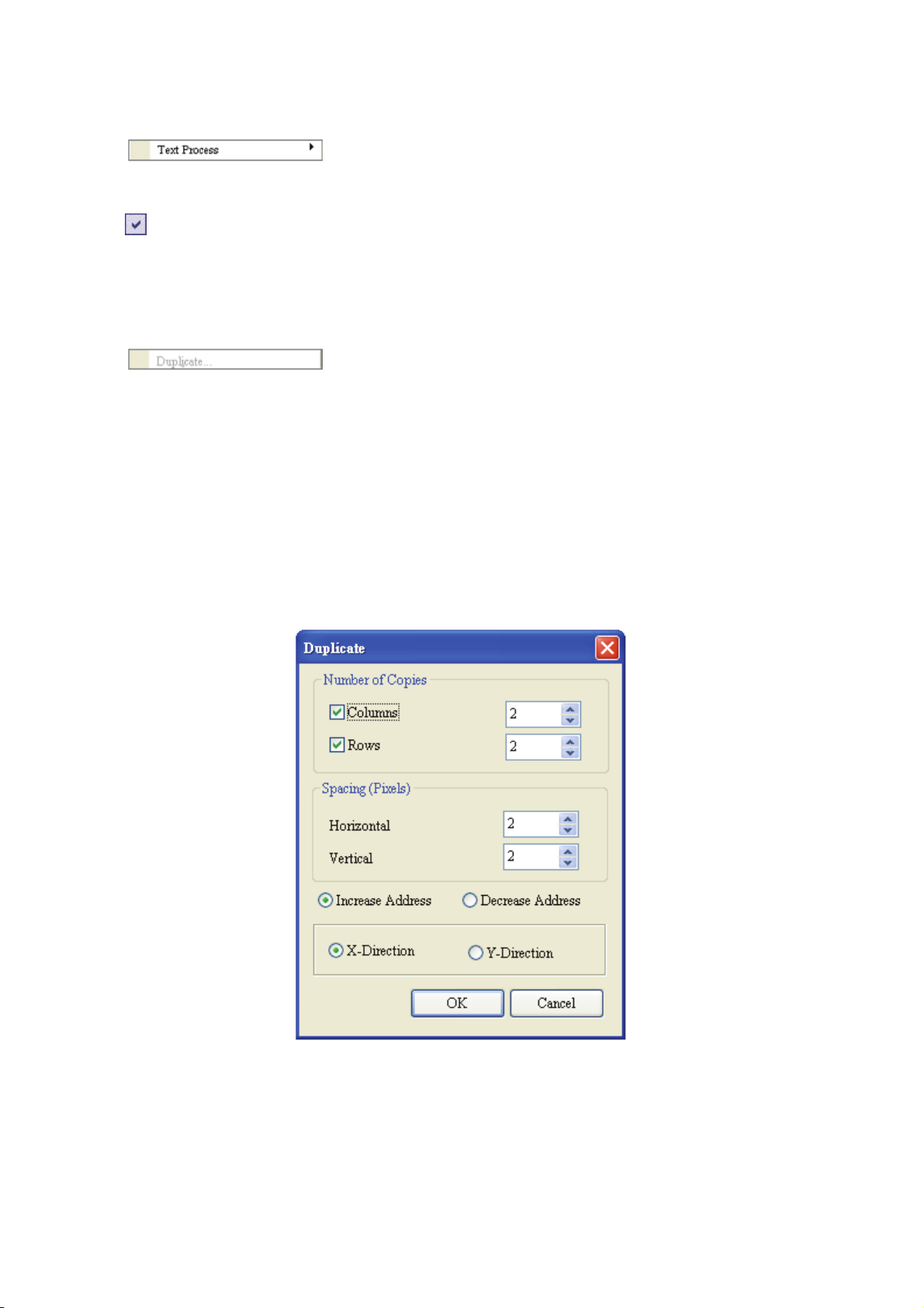
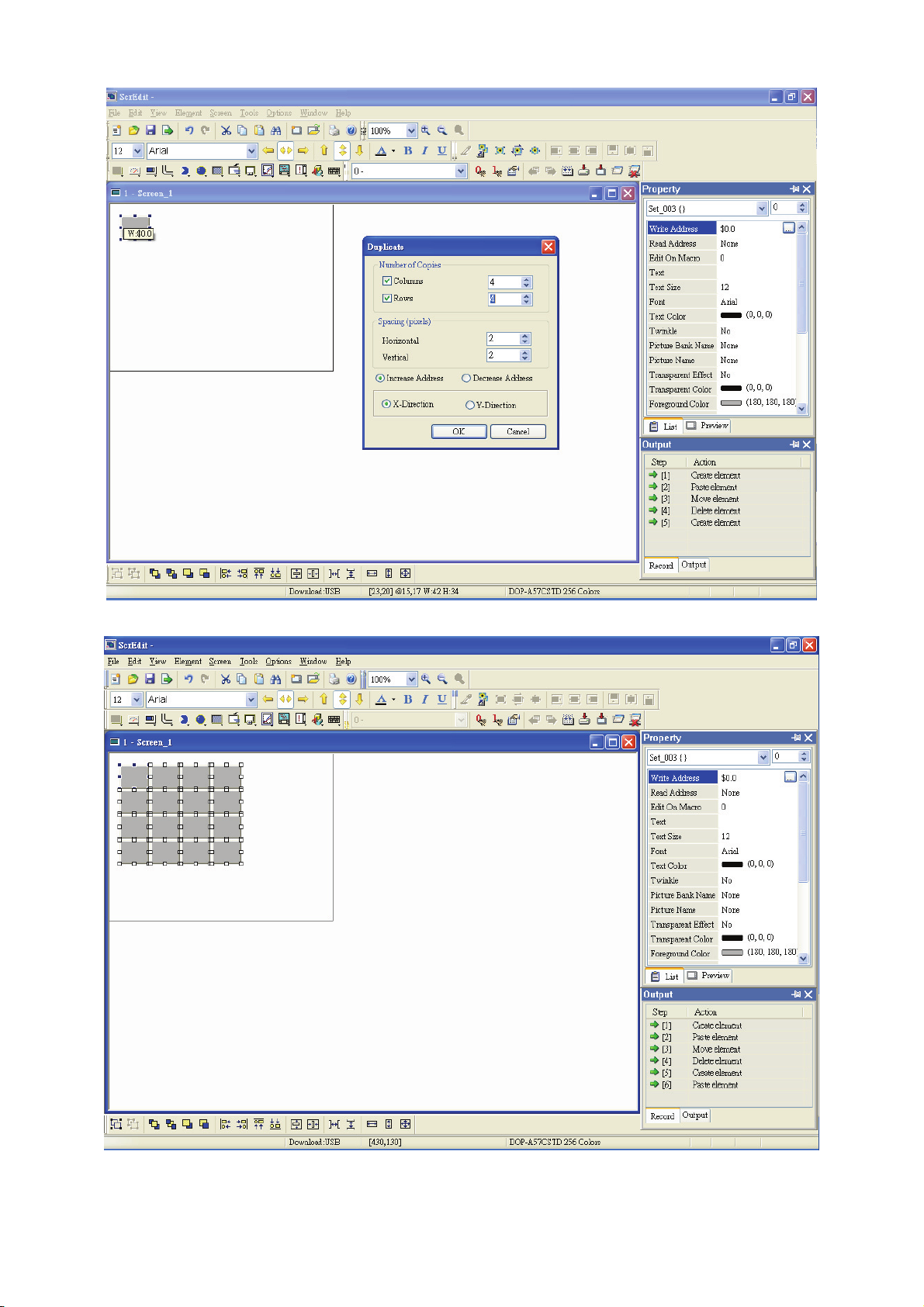
Duplicate
It allows the user to copy one or more elements horizontally and vertically at the same time. After
selecting this function by choosing Edit > Duplicate from menu bar, the Fig. 2.4.7 dialog box will show
up. The user can enter the number of columns and rows to get the total copy numbers. If the user only
wants to copy the number of Rows, please uncheck the box next to Columns. If the user only wants to
copy the number of Columns, please uncheck the box next to Rows.
Spacing (pixels): This option is used to set the spacing by horizontal or vertical direction between every
element. After this option is set, the duplicated elements will be placed in this spacing.
Increase / Decrease Address: This option is used to place the element that the user copies by
ascending or descending address. The unit of the address can be Word or Bit.
X-direction / Y-direction: This option is used to place the element that the user copies by horizontal (Xdirection) or vertical (Y-direction) direction.
Please refer to Fig 2-4-30 and Fig. 2-4-31 for example.
Fig. 2.4.7 Duplicate dialog box
Revision Apr. 30th, 2007, 2007PDD23000002 2-29
Page 41
Chapter 2 Creating and Editing Screens|ScrEdit Software User Manual
Fig. 2.4.8 Duplicate Example 1
Fig. 2.4.9 Duplicate Example 2
2-30 Revision Apr. 30th, 2007, 2007PDD23000002
Page 42

Chapter 2 Creating and Editing Screens|ScrEdit Software User Manual
2.5 Menu Bar and Toolbar (View)
View
Toolbars
Docking windows
Fig. 2.5.1 View options
In View option, the user can decide how toolbars and docking windows display. Once the user clicks on it, it
will have icon
windows by themselves. If
display on the screen. The description of each toolbar is introduced in the following sections.
Standard Toolbar
in front of it and display on screen. The user can also arrange these toolbars and docking
not show in front of the toolbar, it indicates that the toolbar is hided and not
Table 2.5.1 Standard toolbar
Icon Function Description
New Create a new project
Open Open an old project
Save Save current edited project
Export Export an project to BMP format
Revision Apr. 30th, 2007, 2007PDD23000002 2-31
Undo Undo an action (some can’t be undo)
Redo Redo an action
Cut Cut selected elements
Copy Copy selected elements
Page 43

Chapter 2 Creating and Editing Screens|ScrEdit Software User Manual
Icon Function Description
Status Bar
Display current editing states.
Text Format Toolbar
Paste Paste the element the user copy or cut
Find Find specific text, write address or read address
New Screen Create a new screen
Open Screen Open an old screen
Print Print current project
Help Screen editor version
Fig. 2.5.2 Status bar
Table 2.5.2 Text toolbar
Icon Function Description
Font Size Display and change text size
Font Name Display and change text font
Align Left Align text to left
Center Horizontal
Align Right Align text to right
Align Top Align text to top
Center Vertical
Align Bottom Align text to bottom
Text Color Change text color
The space at the right/left sides of text will be the
same
The space at the top/bottom sides of text will be the
same
2-32 Revision Apr. 30th, 2007, 2007PDD23000002
Bold Text bold
Italic Text Italic
Underline Add line under text
Page 44

Chapter 2 Creating and Editing Screens|ScrEdit Software User Manual
Bitmap Toolbar
Table 2.5.3 Bitmap toolbar
Icon Function Description
Select Transparent
Picture Stretch 1: 1 Scale the picture relative to original picture size
Color
Chang Mode for
Process All State
Picture
Picture Stretch All Stretch the selected picture to the whole range of the element.
Original Picture Resize the selected picture to the actual picture size
Picture Align Left Align the selected picture to left
Picture Center
Horizontal
Picture Align Right Align the selected element to right
Picture Align Top Align the selected element to top
Picture Center
Vertical
Remove the color of the picture and determine the transparent color
of the picture
If this function is enabled, not only the current picture with current
state but also all pictures with all states will be stretched, resized or
aligned
The space at the right/left sides of the selected picture will be the
same
The space at the top/bottom sides of the selected element will be
the same
Picture Align Bottom Align the selected element to bottom
Element Toolbar
Table 2.5.4 Element toolbar
Icon Function Drop-down Menu
Button
Revision Apr. 30th, 2007, 2007PDD23000002 2-33
Page 45

Chapter 2 Creating and Editing Screens|ScrEdit Software User Manual
Icon Function Drop-down Menu
Meter
Bar
Pipe
Pie
Indicator
Display
Movement
Input
Curve
History
2-34 Revision Apr. 30th, 2007, 2007PDD23000002
Page 46

Chapter 2 Creating and Editing Screens|ScrEdit Software User Manual
Icon Function Drop-down Menu
Alarm
Graphic
Keypad
Build / Layout Toolbar
Build Toolbar
Icon Function Description
Table. 2.5.5 Build toolbar
Current Element State Text on selected element
View State OFF/1 Switch and view current state OFF/1
View State ON/1 Switch and view current state ON/1
Display All Read/Write
Address
Previous windows Select previous windows
Next windows Select the next windows
Display all read/write addresses of all
elements
Download Screen and
Revision Apr. 30th, 2007, 2007PDD23000002 2-35
Compile Compile current element
Recipe
Download Screen Download screen data
On-line Simulation
Off-line Simulation
Download screen data and recipe
Test editing file at PC side and it needs to
connect to the controller
Test editing file at PC side and it doesn’t
need to connect to the controller
Page 47

Chapter 2 Creating and Editing Screens|ScrEdit Software User Manual
Layout Toolbar
Table. 2.5.6 Layout toolbar
Icon Function Description
Group Group the selected elements
Ungroup Ungroup the selected elements
Bring to Front
Send to Bottom
Bring Forward
Send Backward Move the selected element behind one position
Align Left Align the selected elements to left
Align Right Align the selected elements to right
Align Top Align the selected elements to top
Align Bottom Align the selected elements to bottom
Center Vertically
Move the selected element to the front of all
other elements
Move the selected element behind all other
elements
Move the selected element forward one
position
Set the element to be the vertical position of
the work place
Set the element to be the horizontal position of
the work place
Make all the elements align in a consistent
width
Make all the elements align in a consistent
height
Make the selected elements to be the same
width
Make the selected elements to be the same
height
Make the selected elements to be the same
size
Zoom Toolbar
Center Horizontally
Across Space Evenly
Down Space Evenly
Make Same Width
Make Same Height
Make Same Size
Table. 2.5.7 Zoom toolbar
Icon Function Description
Display Level
Lets the user set a zoom level, including 25%, 50%, 75%, 100%, 150%,
200% and 300%
2-36 Revision Apr. 30th, 2007, 2007PDD23000002
Zoom In
Lets the user change the magnification level, including 150%, 200%
and 300%.
Page 48

Chapter 2 Creating and Editing Screens|ScrEdit Software User Manual
Icon Function Description
Property Table
Element property table. Please refer to Chapter 3 for detailed description.
Zoom Out
1:1 Lets the user change element size to actual size (100%).
Lets the user reduce the magnification level, including 25%, 50% and
75%.
Fig. 2.5.3 Property table
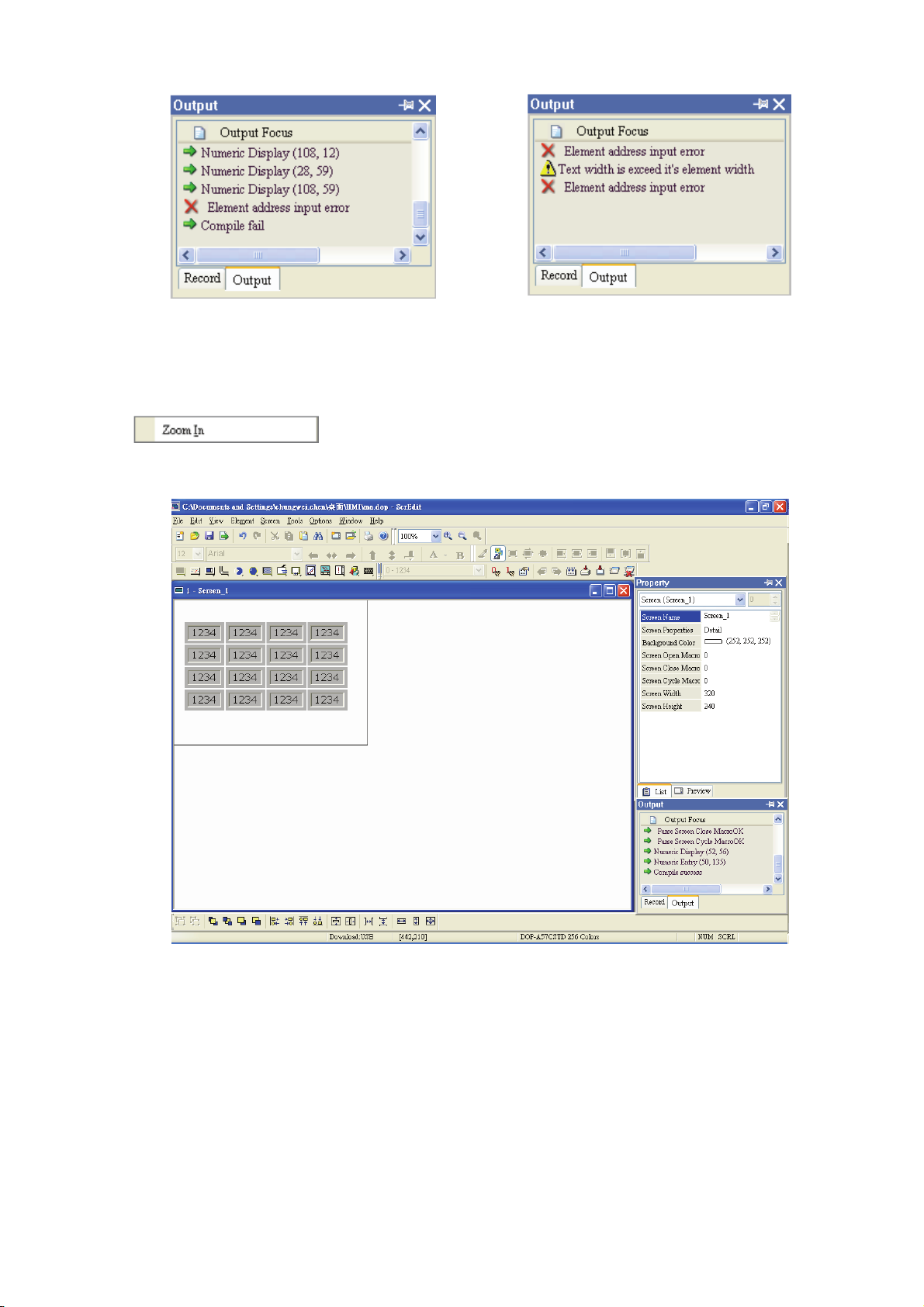
Output Window
All editing processes during compile operation will be shown here for user’s reference. It can let the
user know the result of the compile operation and it is also convenient for tracing error address when
creating and editing screen (See Fig. 2.5.4, Fig. 2.5.5, Fig. 2.5.6 and Fig. 2.5.7).
Fig. 2.5.4 Output window
Fig. 2.5.5 Output window during compile operation
Revision Apr. 30th, 2007, 2007PDD23000002 2-37
Page 49
Chapter 2 Creating and Editing Screens|ScrEdit Software User Manual
Fig. 2.5.6 Output result of compile operation
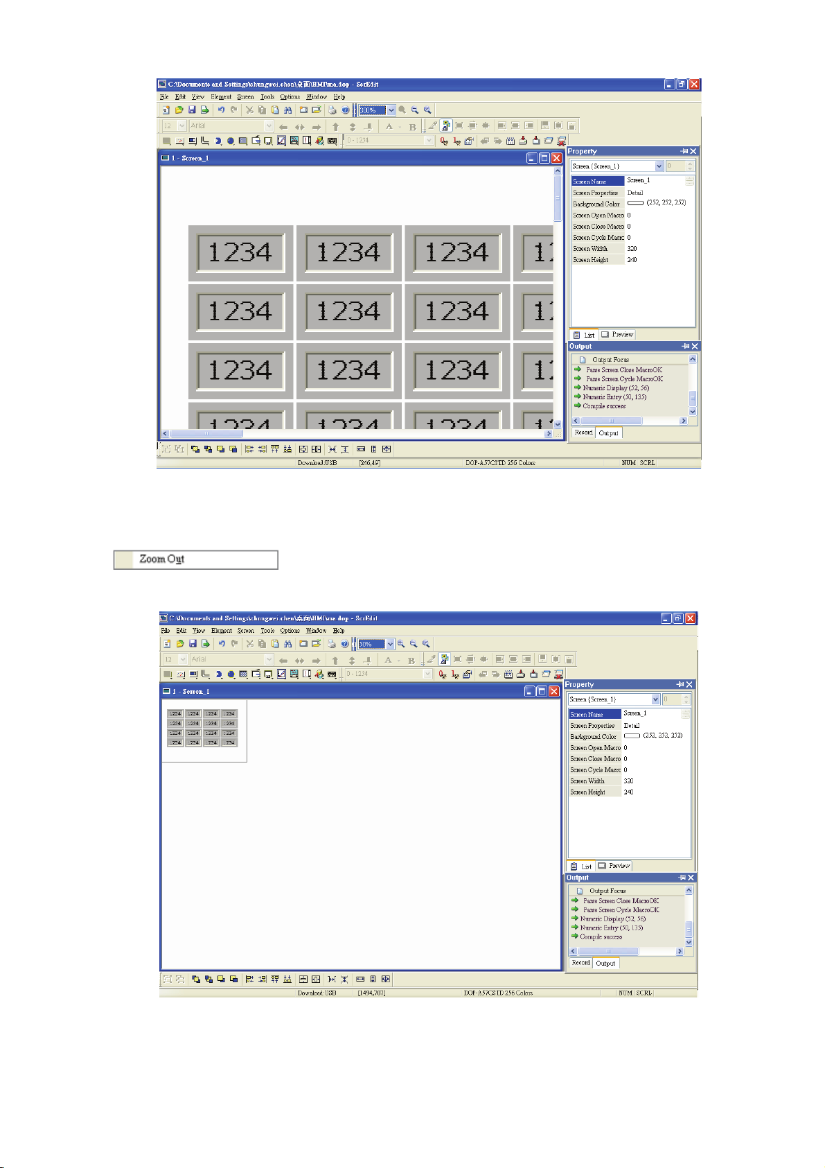
Zoom In
Zoom in to get a close look at the elements on ScrEdit work place. (Refer to Fig. 2.5.8, Fig. 2.5.9)
Fig. 2.5.7 Error output
Fig. 2.5.8 Zoom level = 100% (Before Choosing Zoom In command)
2-38 Revision Apr. 30th, 2007, 2007PDD23000002
Page 50
Chapter 2 Creating and Editing Screens|ScrEdit Software User Manual
Fig. 2.5.9 Zoom level = 300% (After Choosing Zoom In command)
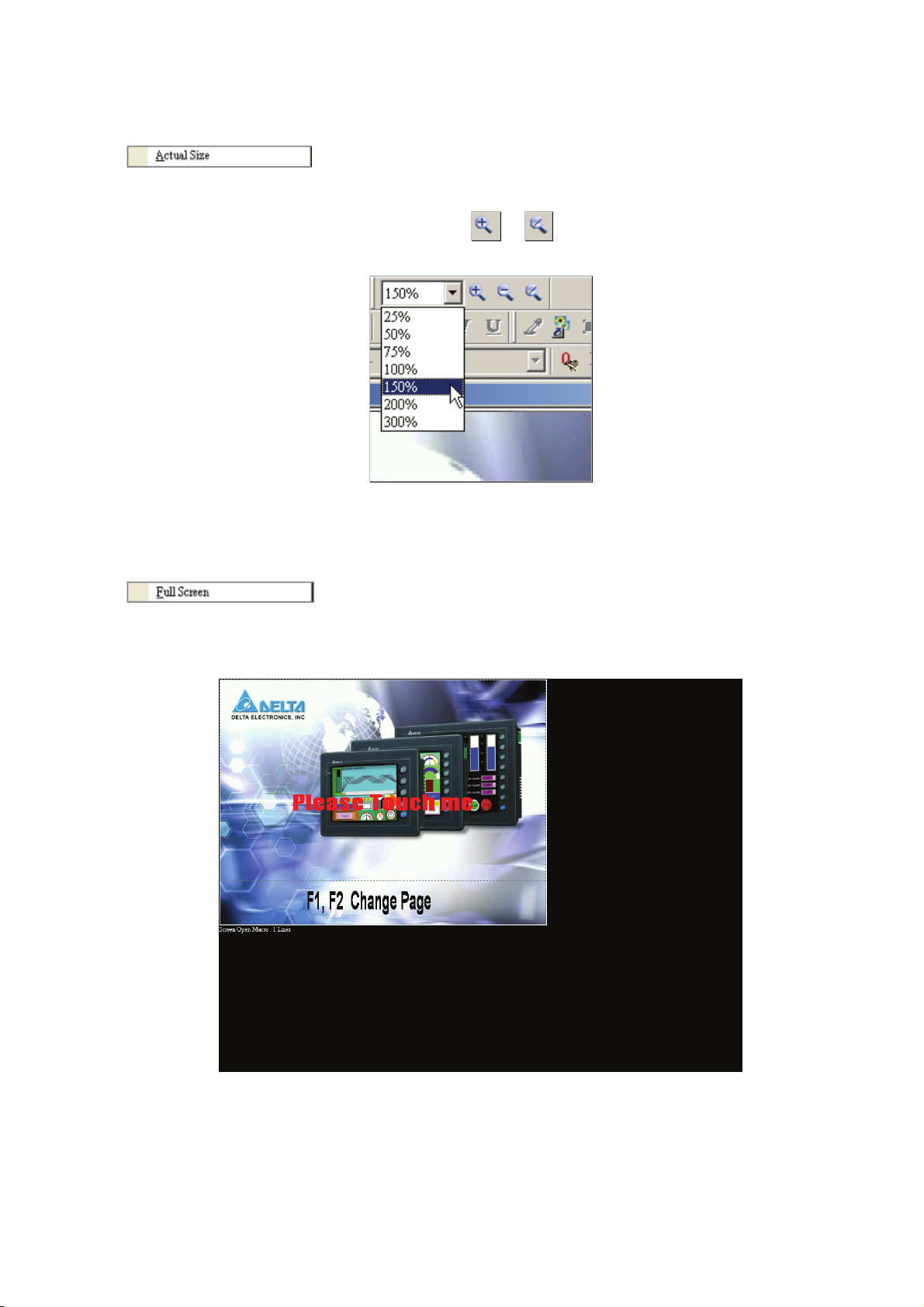
Zoom Out
Zoom out to see more look of the elements on ScrEdit work place. (Refer to Fig. 2.5.10)
Fig. 2.5.10 Zoom level = 50% (After Choosing Zoom Out command)
Revision Apr. 30th, 2007, 2007PDD23000002 2-39
Page 51
Chapter 2 Creating and Editing Screens|ScrEdit Software User Manual
Actual Size
Return to actual size (100%). This size is relative to the screen size of HMI.
The user can also zoom in or out by clicking icon or or selecting the Zoom level directly (Fig.
2.5.11).
Fig. 2.5.11 Zoom level
Full Screen
As Fig. 2.5.12. Full screen provides maximum view to edit in ScrEdit. Full screen view will hide all
toolbars and docking windows other than the ScrEdit work place itself. Fig. 2.5.12 full screen also
shows the reference macro command.
Fig. 2.5.12 Full Screen (Pressing Esc key or left-click the mouse can exit Full screen)
2-40 Revision Apr. 30th, 2007, 2007PDD23000002
Page 52
Chapter 2 Creating and Editing Screens|ScrEdit Software User Manual
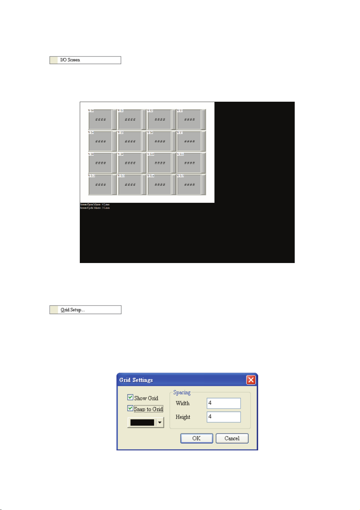
I/O Screen
As Fig. 2.5.13. I/O screen also provides maximum view to edit in ScrEdit just like Full screen. But the
difference is that I/O Screen will show the read and write addresses of the element and also shows the
set macro commands.
Fig. 2.5.13 I/O Screen (Pressing Esc key or left-click the mouse can exit Full screen)
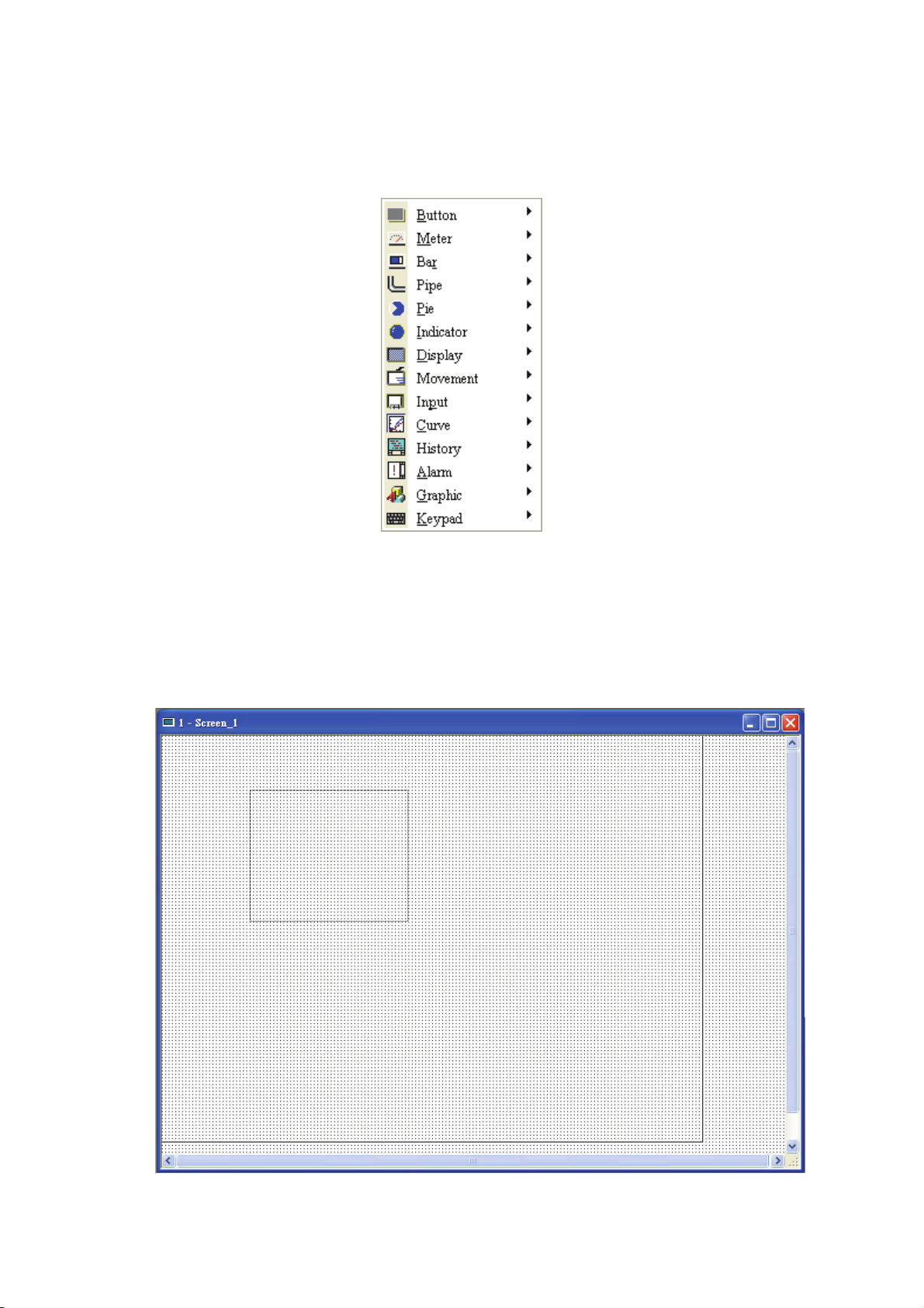
Grid Setup
Grid Setup is a function that can help the user to align and position the element more easily and
precisely. The distance (spacing) between the grid dots can be set by the user freely (Fig. 2.5.14 and
Fig. 2.5.15).
Show Grid: Show the grid dots on the screen.
Snap to Grid: Make the elements snap to grid so that the elements can jump between grid lines when
the user moves them.
Fig. 2.5.14 Gird Settings dialog box
Revision Apr. 30th, 2007, 2007PDD23000002 2-41
Page 53

Chapter 2 Creating and Editing Screens|ScrEdit Software User Manual
Fig. 2.5.15 Show Gird screen
2-42 Revision Apr. 30th, 2007, 2007PDD23000002
Page 54
Chapter 2 Creating and Editing Screens|ScrEdit Software User Manual
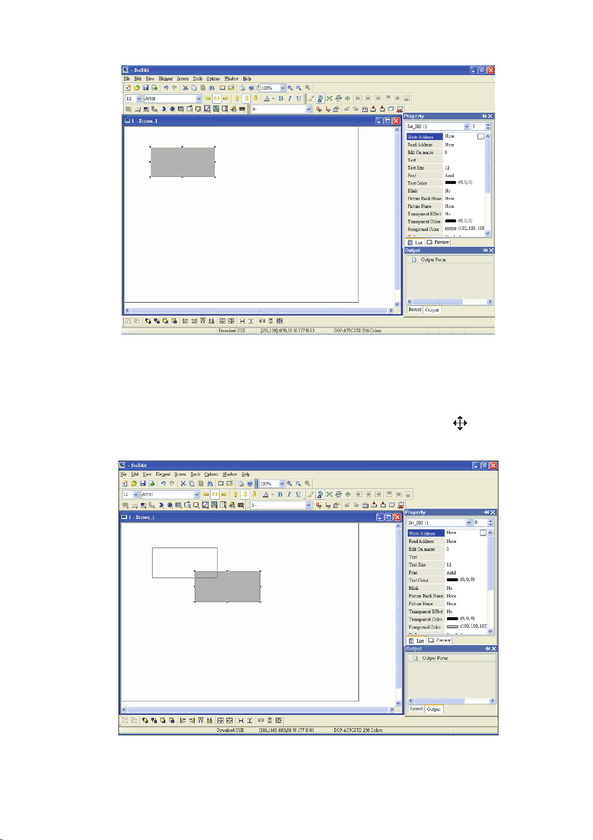
2.6 Menu Bar and Toolbar (Element)
Element
Fig. 2.6.1 Element options
Screen editor provides 14 types of elements and there are many styles for each type. These 14 types
include Button, Meter, Bar, Pipe, Pie, Indicator, Display (data display), Movement (graph display), input,
curve, history (sampling), alarm, graphic and, keypad, etc. The user can select a desired element from the
pull-down menu and drag the size needed on ScrEdit work place (as Fig. 2.6.2 and Fig. 2.6.3).
Fig. 2.6.2 Drag mouse to determine the element size
Revision Apr. 30th, 2007, 2007PDD23000002 2-43
Page 55

Chapter 2 Creating and Editing Screens|ScrEdit Software User Manual
Fig. 2.6.3 Element display (Create an element)
The user can also right-click the mouse to select the desired element. For the property of each element,
please refer to Chapter 3 for detailed description.
Create an Element
The user can select an element by right-clicking the mouse in work place. Place your mouse pointer in
work place and right-click the mouse to get pull-down menu. Then, the user can select the desired
element and determine the element size by left-clicking the mouse. Later set the property of the
element (Fig. 2.6.4, Fig. 2.6.5, Fig. 2.6.6 and Fig. 2.6.7).
Fig. 2.6.4 Right-click the mouse to select the element
2-44 Revision Apr. 30th, 2007, 2007PDD23000002
Page 56

Chapter 2 Creating and Editing Screens|ScrEdit Software User Manual
Fig. 2.6.5 Select an element by choosing Element command from menu bar
Fig. 2.6.6 Drag with left mouse button (Left-click the mouse, hold it to drag and release it to finish)
Revision Apr. 30th, 2007, 2007PDD23000002 2-45
Page 57
Chapter 2 Creating and Editing Screens|ScrEdit Software User Manual
Fig. 2.6.7 Release left mouse button to create an element
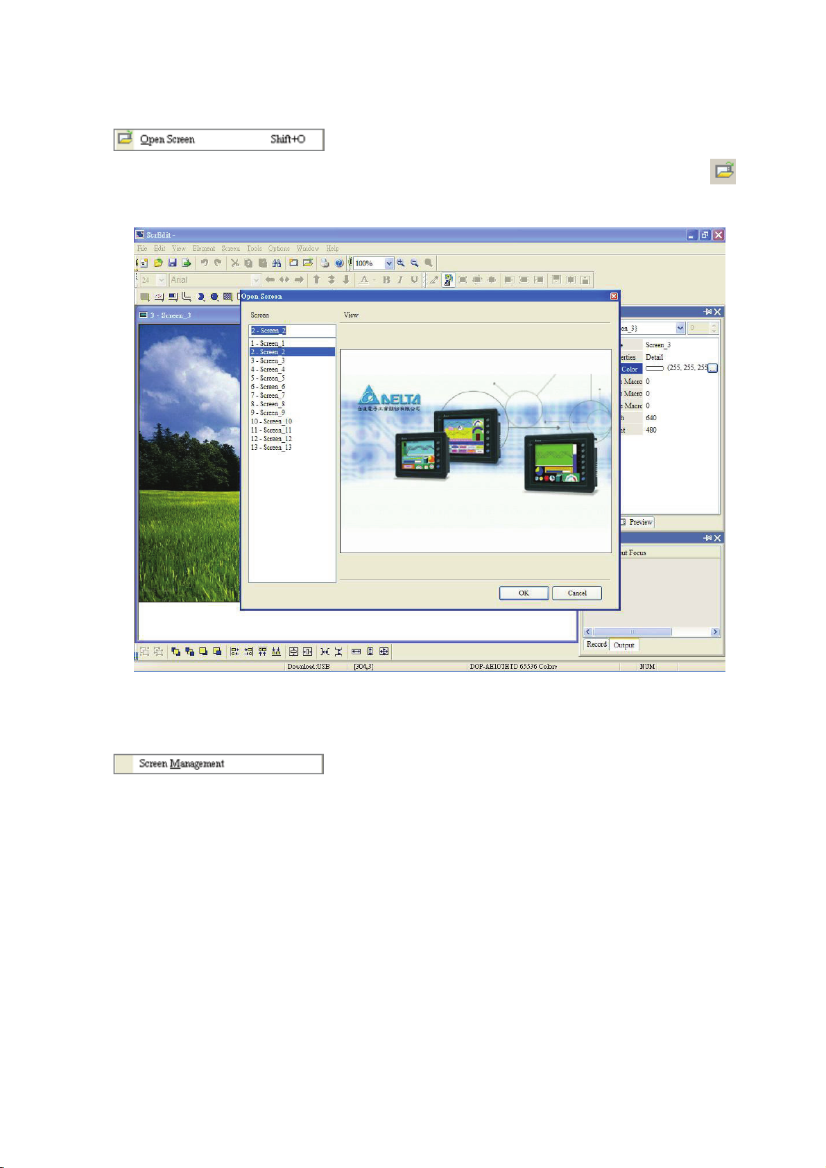
Move an Element
The user can use the mouse to move an element. Mouse operation is the same as working in
Windows® operating system. When the mouse cursor changes to a four-arrow icon
left-click the mouse and move the element freely (Fig. 2.6.8).
, the user can
Fig. 2.6.8 Move an Element
2-46 Revision Apr. 30th, 2007, 2007PDD23000002
Page 58

Chapter 2 Creating and Editing Screens|ScrEdit Software User Manual
Modify Element Width
The user can also use the mouse to modify the width of an element. When the mouse cursor changes
to a two-arrow icon
, the user can left-click the mouse and modify the element width (Fig. 2.6.9).
Fig. 2.6.9 Modify Element Width
Modify Element Height
The user can also use the mouse to modify the height of an element. When the mouse cursor changes
to a two-arrow icon
, the user can left-click the mouse and modify the element height (Fig. 2.6.10).
Fig. 2.6.10 Modify Element Height
Revision Apr. 30th, 2007, 2007PDD23000002 2-47
Page 59

Chapter 2 Creating and Editing Screens|ScrEdit Software User Manual
Modify Element Width and Height Simultaneously
The user can also use the mouse to modify the width and height of an element simultaneously. When
the mouse cursor changes to a two-arrow icon
the element width and height at the same time (Fig. 2.6.11).
Fig. 2.6.11 Modify Element Width and Height Simultaneously
or , the user can left-click the mouse and modify
Input Characters
The user can input a string of characters that Windows® operating system accepts in the property
table. When the mouse cursor changes to an icon
Windows® operating system accepts where the cursor
, the user can start to input any characters that
blinks (Fig. 2.6.12).
Fig. 2.6.12 Input Characters
2-48 Revision Apr. 30th, 2007, 2007PDD23000002
Page 60

Chapter 2 Creating and Editing Screens|ScrEdit Software User Manual
Right-click the Mouse
The user can find that different menu will pop up when right-clicking the mouse (Fig. 2.6.13, Fig. 2.6.14
and Fig. 2.6.15).
Fig. 2.6.13 Right-click the mouse on Toolbar - Toolbars window
Fig. 2.6.14 Right-click the mouse in Work Place - Element Selection
Revision Apr. 30th, 2007, 2007PDD23000002 2-49
Page 61

Chapter 2 Creating and Editing Screens|ScrEdit Software User Manual
Fig. 2.6.15 Right-click the mouse on the element - Editing options (Layout Toolbar)
Cross Reference Table
When creating and editing various kinds of elements, what usually happens is that the repeat use of the
same address. In order to avoid this situation, ScrEdit provides the cross reference table function for
the user’s convenience and quick reference. The user can view the read and write addresses of the
selected element and see their relationship or connection with the addresses of other elements, macro
commands or system control area. The user can see how to choose Cross Reference Table
command from menu bar. Fig. 2.6.16 is one simple example to introduce the usage of this function.
The first row of the cross reference table displays the referred element the user selected and the other
rows below the first row displays the elements which have the same write address. The user can
double-click the row and ScrEdit will switch to the corresponding screen of the referred address
automatically. In Fig.2.6.16, ScrEdit switches to the corresponding screen of the referred address
automatically and select the reference element.
Fig. 2.6.16 Cross Reference Table dialog box
2-50 Revision Apr. 30th, 2007, 2007PDD23000002
Page 62

Chapter 2 Creating and Editing Screens|ScrEdit Software User Manual
Element Part List
When Element Part List function is enabled, ScrEdit will sort out and classify all the elements on the
current screen. The user can click the tab to switch to the classification that the user wants to view. The
related addresses and corresponding properties will be listed in each classification (Name, Describe,
Write / Read address, Trigger address, Trigger type, Interlock and Level) in each tab (Fig. 2.6.17). The
user can double-click the column to let ScrEdit select the element automatically and allow the user to
edit the detailed property of the selected element in property table.
Fig. 2.6.17 Element Part List dialog box
Revision Apr. 30th, 2007, 2007PDD23000002 2-51
Page 63

Chapter 2 Creating and Editing Screens|ScrEdit Software User Manual
2.7 Menu Bar and Toolbar (Screen)
Screen
In Screen options, ScrEdit provides some screen editing functions (Fig. 2.7.1). Please refer to the following
sections for more detailed introduction.
Fig. 2.7.1 Screen options
If the user presses the close box, it will hide the current screen without exiting. In Windows, it will exit the
current screen by clicking close box and remind the user to save before exiting. However, in ScrEdit
environment, the current screen will not be deleted and it will not remind the user to save. The function of
clicking the close box only hides the current screen.
New Screen
Create a new screen. The user can choose Screen > New Screen or click the New Screen icon
or use keyboard shortcuts by pressing Shift + N to open a new editing screen. The new screen can be
named and numbered by the user. The setting dialog box is shown as Fig. 2.7.2.
,
Fig. 2.7.2 New Screen dialog box
2-52 Revision Apr. 30th, 2007, 2007PDD23000002
Page 64
Open Screen
Chapter 2 Creating and Editing Screens|ScrEdit Software User Manual
Open an old screen. The user can choose Screen > Open Screen or click the Open Screen icon
or use keyboard shortcuts by pressing Shift + O. When choosing open screen, the user can preview
each screen in Open Screen dialog box (Fig. 2.7.3).
,
Fig. 2.7.3 Open Screen dialog box
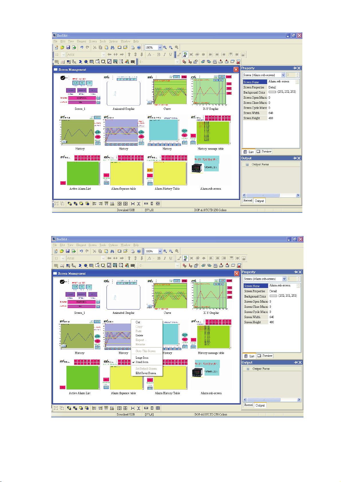
Screen Management
When Screen Management function is enabled (Fig. 2.7.4), the user can duplicate, paste and cut the
screen using the mouse, just like the function of Windows Explorer in Windows® operating system. In
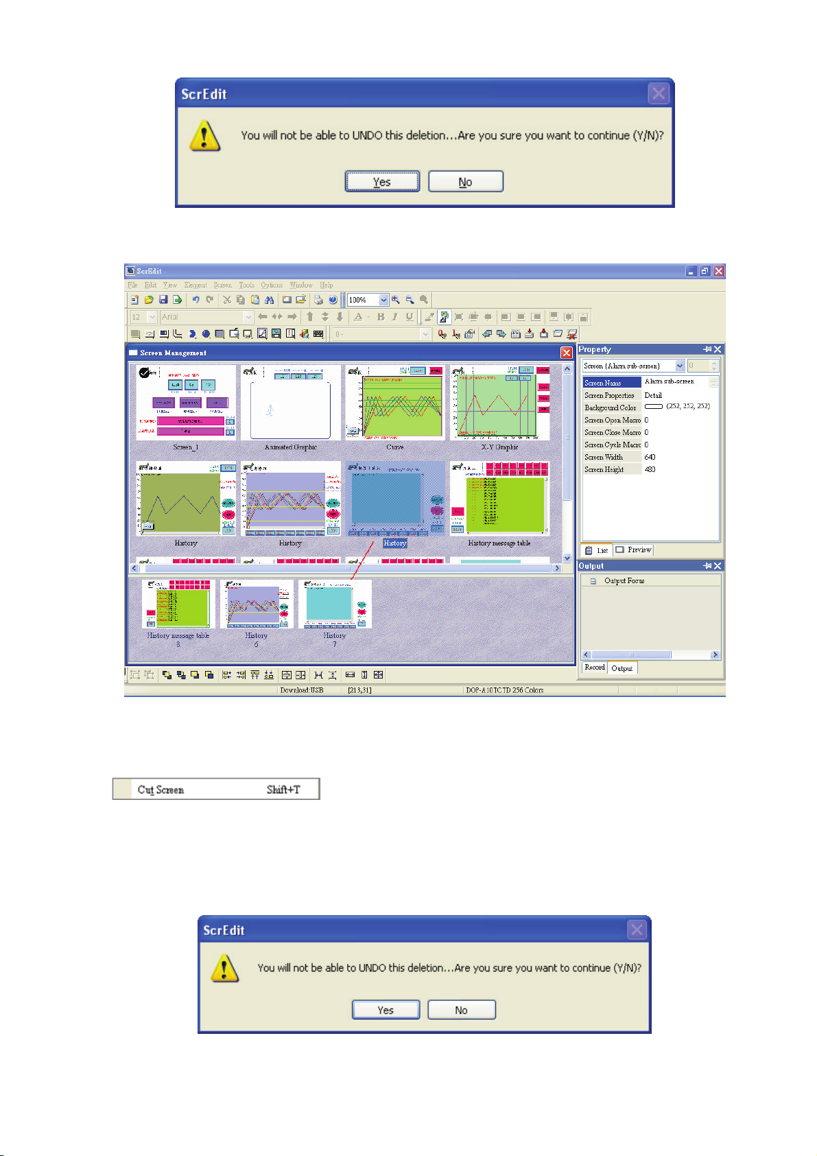
Screen Management dialog box, the user can right click the mouse to manage all of the screens (Fig.
2.7.5). Please note that the user cannot undo the action of cut screen. It is the same as delete screen
that screen will be lost but it can be pasted to get the same screen (Fig. 2.7.6). Besides, right-click the
mouse to select the Edit Save Screen function, and then the user can drag the mouse to determine
the screen saver display (Fig. 2.7.7). For the setting of screen saver, please click Options >
Configuration > Other.
Revision Apr. 30th, 2007, 2007PDD23000002 2-53
Page 65
Chapter 2 Creating and Editing Screens|ScrEdit Software User Manual
Fig. 2.7.4 Screen Management dialog box
Fig. 2.7.5 Right-click the mouse
2-54 Revision Apr. 30th, 2007, 2007PDD23000002
Page 66
Chapter 2 Creating and Editing Screens|ScrEdit Software User Manual
Fig. 2.7.6 Warning message after screen is cut
Fig. 2.7.7 Drag the mouse to determine the screen saver display
Cut Screen
Cut whole screen to clipboard, just like the Microsoft Office Clipboard function. The difference is that
Microsoft Office Clipboard allows the user to cut text and graphic items and the Cut Screen function
only allows the user to cut a whole screen. The user can execute this function by choosing Screen >
Cut Screen, or use keyboard shortcuts by pressing Shift + T.
Please note that the user cannot undo the action of cut screen. It is the same as delete screen
that screen will be lost but it can be pasted to get the same screen (Fig.2.7.8).
Fig. 2.7.8 Cut Screen message
Revision Apr. 30th, 2007, 2007PDD23000002 2-55
Page 67

Chapter 2 Creating and Editing Screens|ScrEdit Software User Manual
Copy Screen
Copy whole screen. The user can execute this function by clicking Screen > Copy Screen or use
keyboard shortcuts by pressing Shift + C.
Paste Screen
The user can paste a screen by clicking Screen > Paste Screen or use keyboard shortcuts by pressing
Shift + P. All screen setting will be the same as original screen after pasting but the screen number will
be given automatically by ScrEdit.
Delete Screen
Delete the current editing screen or element. The user can delete a screen by clicking Screen > Delete
Screen or use keyboard shortcuts by pressing Shift + D.
Please note that after executing Delete Screen, the user cannot undo the action of delete screen
(Fig.2.7.9).
Fig. 2.7.9 Delete Screen Message
Export
Export an project to BMP format. The user can execute this function by clicking Screen > Export or
clicking the Export icon
Import
Import a picture to be the background of the editing screen. Please note that this background of the
editing screen is different than the base screen. The nature of an imported picture differs greatly from
that of the base screen. The imported picture cannot exist in ScrEdit as an element. However, the base
screen can be regarded as an element and then exist in the editing screen after a compile operation is
completed (The definition and usage of the base screen will be introduced more in the section of
“Screen Properties”). The file types of available imported picture can be BMP, JPG and GIF, etc. The
user can execute this function by clicking Screen > Import or use keyboard shortcuts by pressing Shift
+ I.
, or use keyboard shortcuts by pressing Shift + E.
2-56 Revision Apr. 30th, 2007, 2007PDD23000002
Page 68
Chapter 2 Creating and Editing Screens|ScrEdit Software User Manual
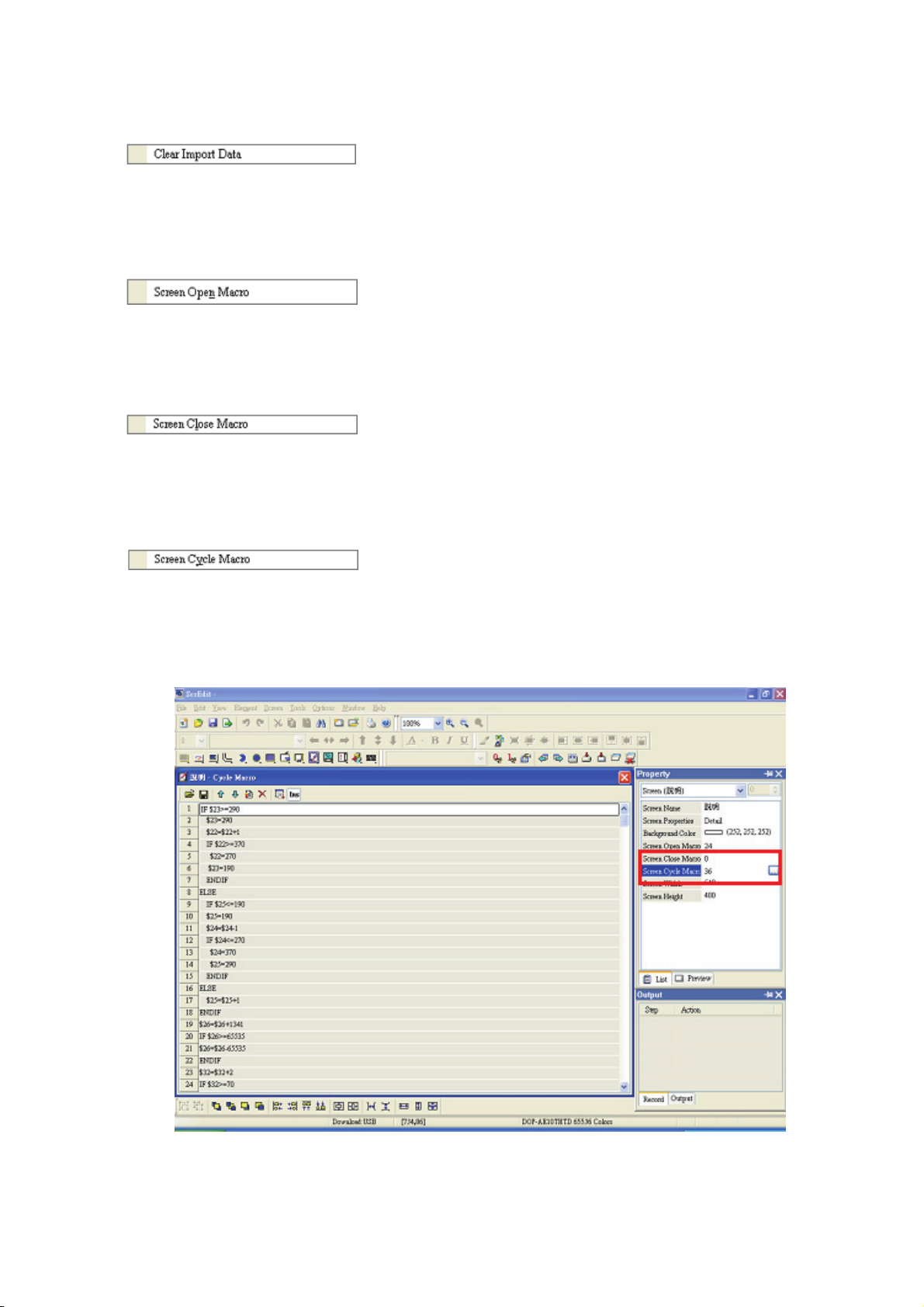
Clear Import Data
The user can free more disk space by clearing the imported data that the user does not want to use.
Execute this function by clicking Screen > Clear Import Data.
Screen Open Macro
When Screen Open Macro function is selected, the Macro will be executed automatically once
opening screen occurs. (Please refer to Chapter 4 for the usage and editing method of Macro.)
Screen Close Macro
When Screen Close Macro function is selected, the Macro will be executed automatically once the
screen is closed. (Please refer to Chapter 4 for the usage and editing method of Macro.)
Screen Cycle Macro
When Screen Cycle Macro function is selected, the Macro will be executed continuously once the
screen is displayed. (Macro will be executed continuously by the cycle time setting) (Please refer to
Chapter 4 for the usage and editing method of Macro.)
The user also can click the Screen Open Macro, Screen Close Macro and Screen Cycle Macro options
from the Property Table to enter intro Screen Open Marco editing environment (Fig. 2.3.10).
Fig. 2.7.10 Screen Open Marco editing environment
Revision Apr. 30th, 2007, 2007PDD23000002 2-57
Page 69
Chapter 2 Creating and Editing Screens|ScrEdit Software User Manual
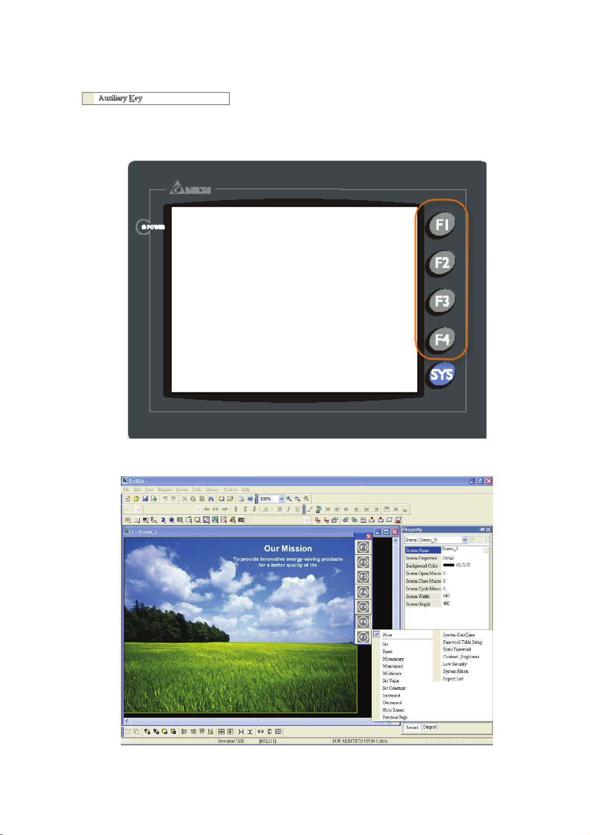
Auxiliary Key
DOP series HMI allows the user to determine the function of auxiliary keys in each screen. The user
can execute this function by clicking Screen > Auxiliary Key. Auxiliary key set up for each screen can
be completed by pressing the auxiliary keys on HMI panel (Fig. 2.7.11) or on the screen (Fig. 2.7.12).
Fig. 2.7.11 Auxiliary Keys on HMI panel
Fig. 2.7.12 Auxiliary Key setting on the screen
2-58 Revision Apr. 30th, 2007, 2007PDD23000002
Page 70
Chapter 2 Creating and Editing Screens|ScrEdit Software User Manual
In Table 2.7.1, the user can see how many user-defined auxiliary keys are available for each model.
Table 2.7.1 Available user-defined auxiliary keys
DOP-A/AE/AS Series Model Name Available User-defined Auxiliary Keys
DOP-AS38BSTD 4
DOP-A (E) 57BSTD 4
DOP-A (E) 57GSTD 4
DOP-A (E) 57CSTD 4
DOP-A75CSTD 6
DOP-AE80THTD 6
DOP-AE94BSTD 11
DOP-A10TCTD 7
DOP-AE10THTD 7
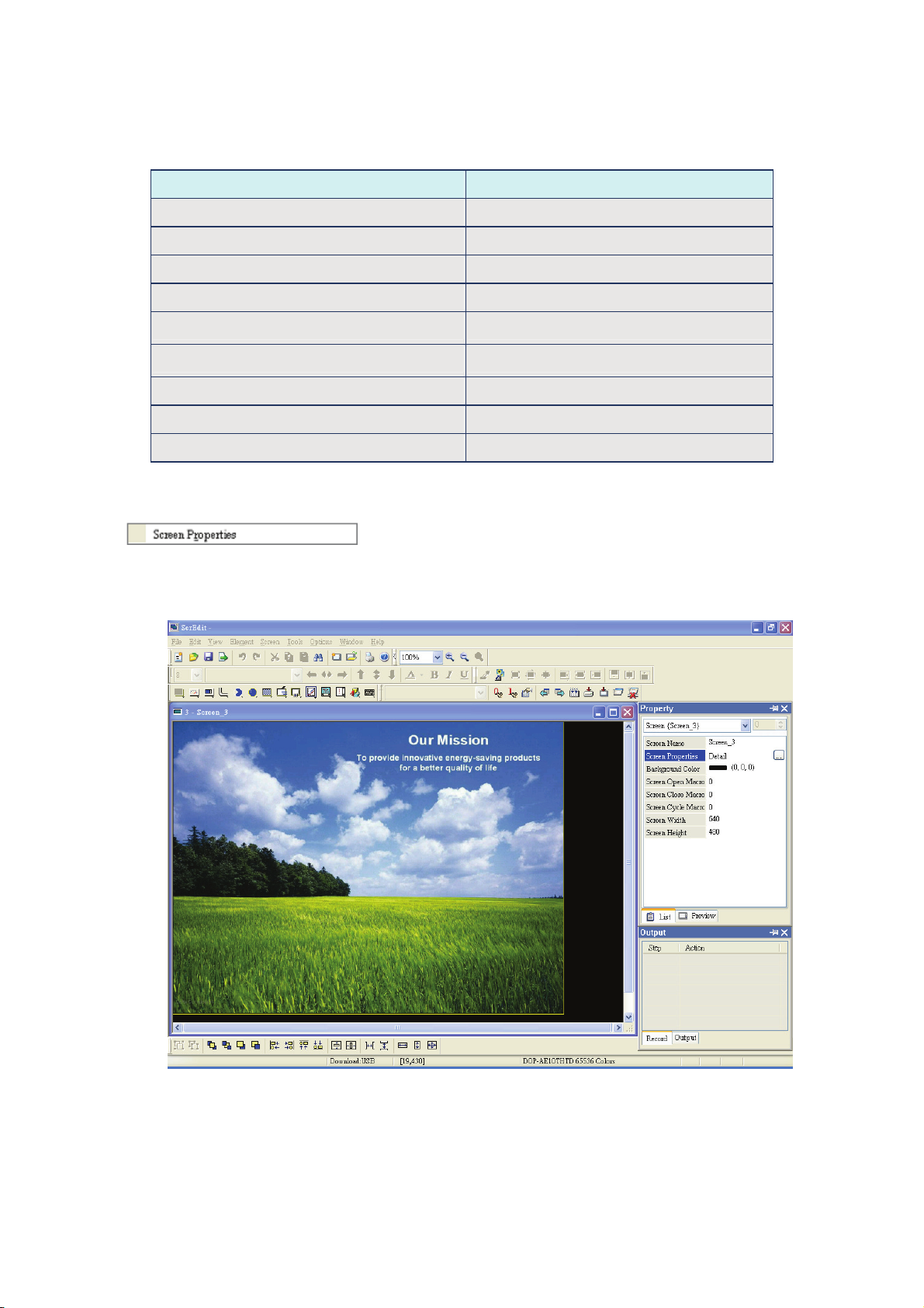
Screen Properties
The user can decide the properties of the current editing screen by clicking Screen > Screen
Properties or choosing Screen Properties from docking windows to set the current screen (Fig.
2.7.13). For the setting of Screen Properties, please refer to Fig. 2.7.14 and Table 2.7.2.
Fig. 2.7.13 Choosing Screen Properties from docking windows
Revision Apr. 30th, 2007, 2007PDD23000002 2-59
Page 71
Chapter 2 Creating and Editing Screens|ScrEdit Software User Manual
A
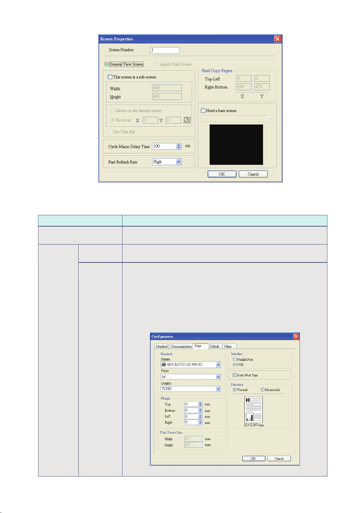
Fig. 2.7.14 Screen Properties dialog box
Table 2.7.2 Screen Properties setting
Function Description
Screen Number The screen number range is within 1~65535 and the number cannot be
repeated.
Screen
pplication
General View
Screen
Apply Print
Screen
Regarded as general view screen. The element created by the user can be
downloaded to HMI after compile operation and display on HMI screen.
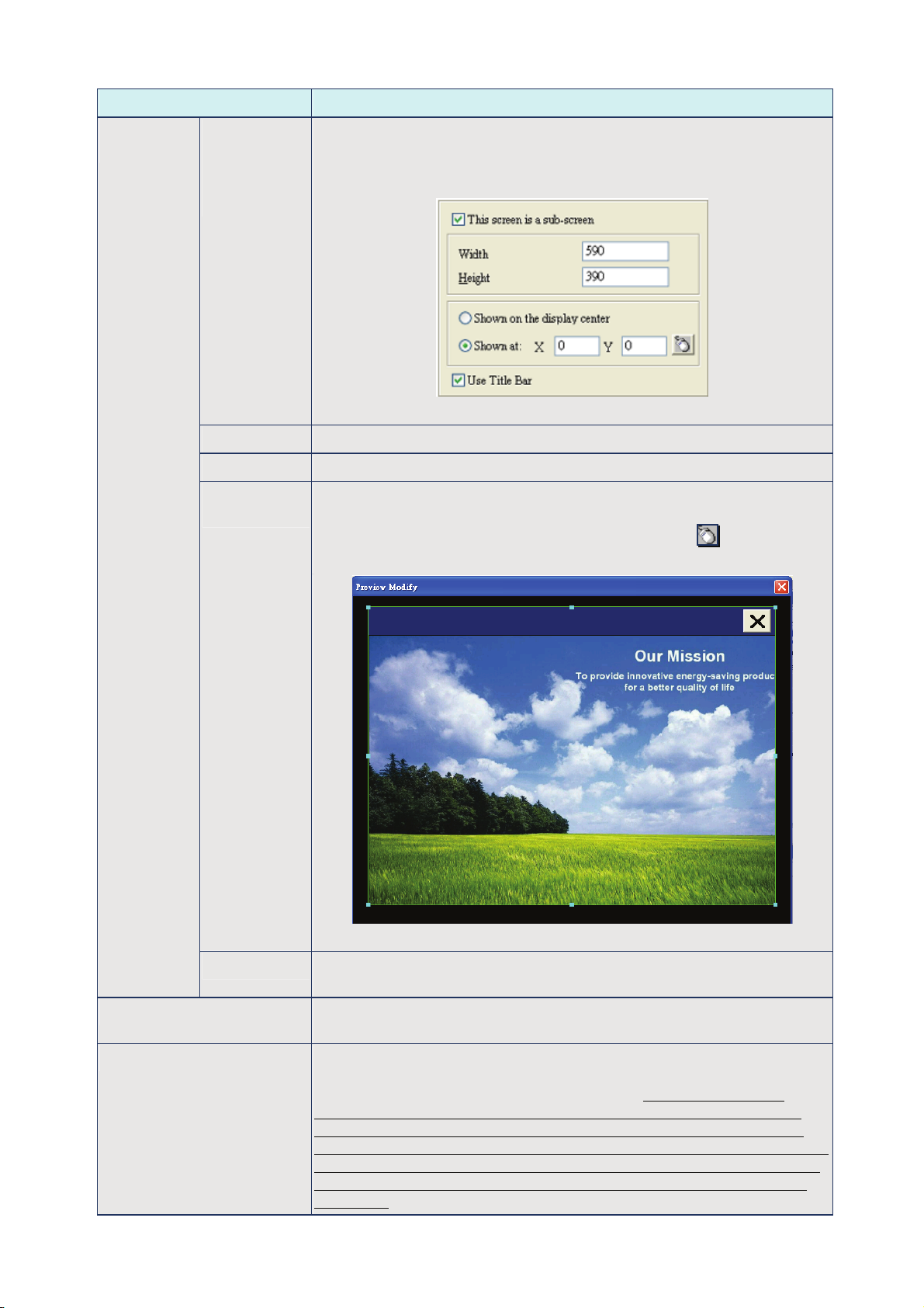
1. Regarded as print screen. The printer can print the element created by
the user after a compile operation. This option is only available in DOP
series HMI which supports printer function.
2. When Apply Print Screen function is selected, the editing range will be
scaled to the actual paper size of the printer. The user can only print
the elements within the range of the paper size. This option is usually
used for print typesetting.
The user can find a printer setting by clicking Option > Configuration >
Print shown as Fig. 2.7.15 below.
Fig. 2.7.15 Print tab in Configuration option
2-60 Revision Apr. 30th, 2007, 2007PDD23000002
Page 72
Chapter 2 Creating and Editing Screens|ScrEdit Software User Manual
Function Description
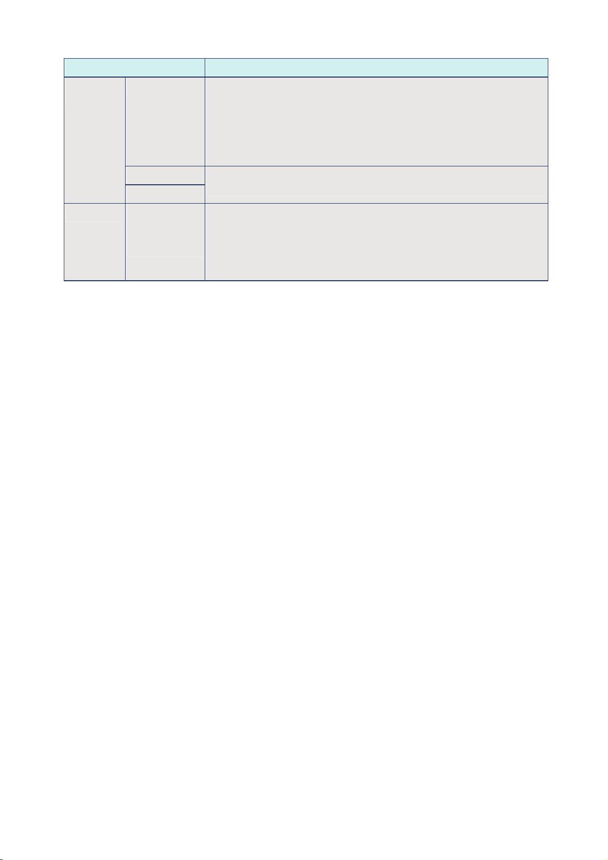
Sub-screen
Setting
Check the
check box next
to “This screen
is a sub-
The check box next to “This screen is a sub-screen” can be checked only
when General View Screen option is selected. Therefore, before setting
sub-screen function, please ensure General View Screen option is
selected.
screen”
Fig. 2.7.16 Sub-screen setting
Width It is used to set the width of sub-screen and the unit is Pixel.
Height It is used to set the height of sub-screen and the unit is Pixel.
Sub-screen
Position
The user can decide if the sub-screen is shown on the center position of
HMI display or specify the display position freely. Only input the coordinate
value directly (X and Y axis) or press the mouse button to drag the
sub-screen to the position the user decided (Fig. 2.7.17).
Fig. 2.7.17 Sub-screen position
Title Bar When the check box next to “Use Title Bar” is checked, the title bar will be
shown when opening sub-screen.
Cycle Macro Delay Time It is used to set Cycle Macro Delay Time when this screen is executed
every time. The range of the cycle macro delay time is within 100ms ~ 5s.
Fast Refresh Rate There are three levels of the Fast Refresh Rate and they are High, Medium
and Low. The purpose of this function is used to make some elements be
displayed immediately when switching screens. Please note that this
function is designed to provide fast value refresh speed for the element
which performs communication frequently. Therefore, it only allows four
elements that can be renewed immediately in each screen. If the user uses
this function on too many elements, it may affect the normal speed of HMI
operation. So, we recommend the user not to activate this function if not
necessary.
Revision Apr. 30th, 2007, 2007PDD23000002 2-61
Page 73
Chapter 2 Creating and Editing Screens|ScrEdit Software User Manual
Function Description
Hard Copy
Region
Base Screen Check the check
Setting The user can find this function only in DOP series HMI which supports
Top-Left
Right-Bottom
box next to
“Need a base
screen”
printer function. If the user wants to enable this function, setting the printer
in advance is necessary. Please go to Option > Configuration > Print
(Fig. 2.7.15) and select the printer first. When this function is enabled, if
one report list button is created and its assigned output device is a printer,
once the user presses the report list button, HMI will refer to the setting in
Hard Copy Region option and execute the screen-printing.
It is used to set the region of HMI printing area (also called Hard Copy
Region) and the unit is Pixel.
Every screen can specify any one of the editing screens as a base screen.
When the check box next to “Need a base screen” is checked, the base
screen will be moved to the back (behind all other elements) as a ground
picture. After compile operation is completed and the screen data is
downloaded to HMI, HMI will execute all of the elements on the base
screen correctly.
2-62 Revision Apr. 30th, 2007, 2007PDD23000002
Page 74

Chapter 2 Creating and Editing Screens|ScrEdit Software User Manual
2.8 Menu Bar and Toolbar (Tools)
Tools
Compile
Fig. 2.8.1 Tool options
It is used to compile editing screen to the format for HMI. During compiling, all of the compiling
messages, including any errors, will be written to output field. When there is any error occurs, system
will remind the user. If there was no error during compiling process, an object file would be produced.
The user can execute this function by clicking Tools > Compile or clicking icon
keyboard shortcuts by pressing Ctrl + F7. If this project is a new project, it will remind the user of
saving before compiling. If this project has been saved or it is an old project, it will compile directly.
After compile operation is finished, ScrEdit will save the file again automatically.
Table 2.8.1 Debug Compiling Error
Debug Compiling Error during Compiling Process
1. Create a new project.
2. Create a button element and a numeric entry element on HMI screen and do not change the
element default property as the Fig. 2.8.2 below.
directly or using
Fig. 2.8.2
Revision Apr. 30th, 2007, 2007PDD23000002 2-63
Page 75

Chapter 2 Creating and Editing Screens|ScrEdit Software User Manual
Debug Compiling Error during Compiling Process
3. When pressing icon to execute compile operation, error message dialog box will pop up to warn
the user of compiling error and show how many errors there are. In Fig. 2.8.3, we can see that there
are two errors occurred and they are all displayed in the output window.
Fig. 2.8.3 Compiling errors during compiling process
4. Once error occurs, the correspondent message will display in output window. The user can click the
error message and ScrEdit will switch to error element window automatically.
Download Screen & Recipe
The user can download screen data and recipe to HMI by clicking Tools > Download Screen &
Recipe or clicking
If PC cannot connect to HMI, the error messages will be displayed and warn the user (Fig. 2.8.5, Fig.
2.8.6, Fig. 2.8.7 and Fig. 2.8.8). The user can set download interface by clicking Options >
Configuration or by clicking Options > Environment. The download interface can be USB or RS-232.
icon directly or using keyboard shortcuts by pressing Ctrl + F8 (Fig. 2.8.4).
2-64 Revision Apr. 30th, 2007, 2007PDD23000002
Page 76

Chapter 2 Creating and Editing Screens|ScrEdit Software User Manual
Fig. 2.8.4 Start to download (the progress will be from 0 to 100%)
Fig. 2.8.5 USB open error message
Fig. 2.8.6 USB disconnect error message
Fig. 2.8.7 Incorrect model name error message
Revision Apr. 30th, 2007, 2007PDD23000002 2-65
Page 77

Chapter 2 Creating and Editing Screens|ScrEdit Software User Manual
Fig. 2.8.8 Not compile error message
Download Screen
It is only used to download screen data to HMI. The user can execute it by clicking Tools > Download
Screen or clicking icon
The download process is the same as the function of Download Screen & Recipe. The only difference
is that the function of Download Screen & Recipe allows the user to download the screen data and
recipe both but the function of Download Screen allows the user to download screen data only. For the
download screen, please refer to Fig. 2.8.4 above.
On Line Simulation
It is used to simulate DOP series HMI by computer but HMI should also connect to PLC first to drive
PLC by PC simulation through PC communication port. Therefore, the user cannot execute the function
of On Line Simulation without connecting PLC. But the user can execute the function of Off Line
Simulation without connecting PLC. On Line Simulation function can execute by clicking Tools > On
Line Simulation or clicking icon
Before executing On Line Simulation, system will ask the user to set the communication port for
connecting to PLC first (Fig. 2.8.9). For On Line Simulation Screen, the user can refer to Fig. 2.8.10.
directly or using keyboard shortcuts by pressing Ctrl + F9.
directly or using keyboard shortcuts by pressing Ctrl + F4.
Fig. 2.8.9 COM Port Setting
2-66 Revision Apr. 30th, 2007, 2007PDD23000002
Page 78

Chapter 2 Creating and Editing Screens|ScrEdit Software User Manual
Fig. 2.8.10 On Line / Off Line Simulation Screen
Off Line Simulation
It is used to test if the editing screen, read/write addresses and Macro on is correct on developed
program without connecting to PLC. The user can execute this function by clicking Tools > Off Line
Simulation or clicking icon
For Off Line Simulation Screen, the user can refer to Fig. 2.8.10.
Recipe
Recipe function provides the controller a convenient parameter input method. The user can transmit the
designated parameter to the controller by using HMI recipe after finishing editing recipe. Bread making
is an example. When making different bread, baking time control is very important. The user can use
Recipe function to meet the different time requirements for making different bread. The purpose of this
function is to reduce the loading of the controller and make the register of the controller to be more
flexible in use.
Recipe function provides an easy and quick parameter input method for the connected controller. When
completing the recipe editing, the user just needs to use the recipe register in control block and the
designated corresponding parameters can be transmitted into the internal memory addresses of the
controller.
Recipe can be set and modified by Recipe Setup dialog box (Fig. 2.8.11) and can be saved and used
independently without project file. Not only 16 bits recipe file (*.rcp), Delta DOP series HMI products
also allow the user to save the recipe data as a 32 bits recipe file (*.csv). Then, the user can edit csv
file in Microsoft Windows@ Excel environment conveniently. Before using recipe, the user should
enable recipe function first by clicking Tools > Recipe. After the recipe function is enabled, the Recipe
Setup dialog box will pop up (Fig. 2.8.11) and then the user can start to edit the recipe. For the setting
of Recipe Setup dialog box, please refer to Table 2.8.2 on next page.
or using keyboard shortcuts by pressing Ctrl + F5.
Revision Apr. 30th, 2007, 2007PDD23000002 2-67
Page 79

Chapter 2 Creating and Editing Screens|ScrEdit Software User Manual
A
Fig. 2.8.11 Recipe Setup dialog box
Table 2.8.2 Recipe Editing
Recipe Setup
Enable Recipe When the check box next to “Enable Recipe” is checked, the recipe function is
enabled. If the user does not enable this function, the user can not do this function
even the user has downloaded recipe data.
ddress The user can input the starting address of recipe data here. It can accept the
address in PLC input format and internal memory format. The user also can click
button to get the address input dialog box (Fig. 2.8.12) to input the starting
address.
Fig. 2.8.12 Input starting address dialog box
2-68 Revision Apr. 30th, 2007, 2007PDD23000002
Page 80
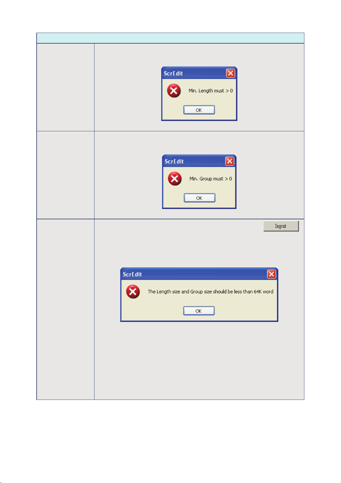
Chapter 2 Creating and Editing Screens|ScrEdit Software User Manual
Recipe Setup
Length It is used to set the recipe length. The unit is Word and it should be set to more
than 0. Otherwise, the following dialog box shown as Fig. 2.8.13 will display on
the screen.
Fig. 2.8.13 Length input error message
Group It is used to set group number of recipe. It is convenient for the user to use recipe
by switching. The group number should be set to more than 0. Otherwise, the
following dialog box shown as Fig. 2.8.14 will display on the screen.
Input
Fig. 2.8.14 Group input error message
After setting length and group number of recipe, the user can click
button to edit the recipe data. The memory size for recipe is limited and the
memory size for recipe is 64K. It indicates that the total recipe size should be less
than 64K (The number of Length x Groups should be less than 65536). If the total
recipe size exceeds the limit, the user will see a warning message shown as Fig.
2.8.15 displayed on the screen.
Fig. 2.8.15 Input error message
The above-mentioned memory means the non-volatile memory of HMI, i.e.
SRAM. Some DOP series HMI, which supports USB host function, allows the user
to use more recipe data via this USB host interface. Supporting USB host function
means it has a built-in USB host interface. The user can connect HMI to a USB
flash drive via this USB host interface and input more recipe data. However, there
is still a limit for the input value of recipe length and groups. When Hold Data
Place is selected as USB flash drive, the length x groups should be less than
4096K (The number of Length x Groups should be less than 4194304). The user
can change the selection of Hold Data Place by clicking Options > Configuration
> Standard. Please refer to Fig. 2.8.16 on next page.
Revision Apr. 30th, 2007, 2007PDD23000002 2-69
Page 81
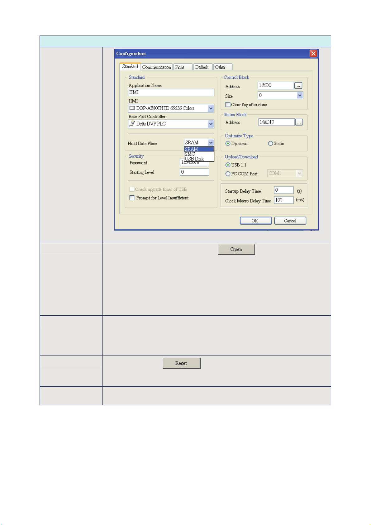
Chapter 2 Creating and Editing Screens|ScrEdit Software User Manual
Recipe Setup
Input
Fig. 2.8.16
Open
The user can load recipe data by clicking button. The loaded recipe
data do not contain the starting address of recipe data. Therefore, regardless of
which brand of the controller connecting to HMI, they all can use the same recipe
file. There are two recipe file types provided in Delta DOP series HMI, one is
16bits recipe file (*.rcp) and the other is 32 bits recipe file (*.csv) that can be
opened in Windows® Excel environment. Please pay close attention to the format
of recipe file and make sure that the recipe file is a 16 bits data or a 32 bits data.
Do not select the incorrect data format; otherwise the program will not work
normally.
Save It is used to save the editing recipe data to be a file. When saving recipe file, the
starting address will not be saved. This lets the user uses the same recipe file in
the different brand of the controller. The user also can save the recipe file as
16bits recipe file (*.rcp) and 32 bits recipe file (*.csv) that can be opened in
Windows® Excel environment.
Reset
When the user clicks button, all related recipe setting and input
recipe data will be deleted. There is no other method to retrieve the recipe except
for using Import function to import the saved recipe data again.
Clear All input recipe will be cleared to 0 (zero) when clear function is selected. Please
refer to Fig. 2.8.17 on next page.
2-70 Revision Apr. 30th, 2007, 2007PDD23000002
Page 82
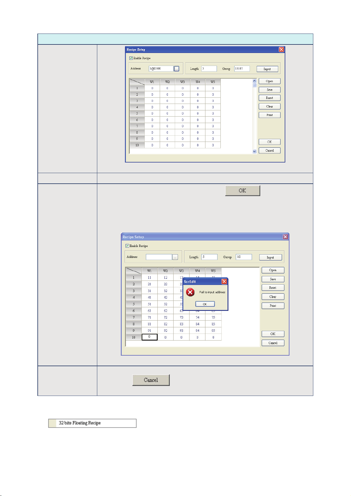
Chapter 2 Creating and Editing Screens|ScrEdit Software User Manual
Recipe Setup
Clear
Fig. 2.8.17
Print It will print all recipe data on current screen.
OK
After inputting the recipe data, the user can click button to save the
recipe data for transmitting or modifying. At the same time, ScrEdit will check the
validity of all input recipe data. If there is invalid input recipe data value, the OK
function will not be executed successfully. For example, in Fig. 2.8.18, ScrEdit
found an error and a warning message dialog box display on the screen as the
user did not input the starting address of the recipe.
Fig. 2.8.18
Cancel It will force the system to exit the Recipe Setup dialog box without saving anything
after clicking button. Therefore, please consider carefully before
clicking this button.
32 bits Floating Recipe
32 bits Floating Recipe function provides the user to save 32 bits data. The data format includes
Signed Decimal, Unsigned Decimal and Floating (The total of Integral and fractional digits cannot
exceed 7 digits). To enable this function, the user can click Tools > 32 bits Floating Recipe. For the
setting of Recipe Setup dialog box, please refer to Fig. 2.8.19 and Table 2.8.3 on next page.
Revision Apr. 30th, 2007, 2007PDD23000002 2-71
Page 83
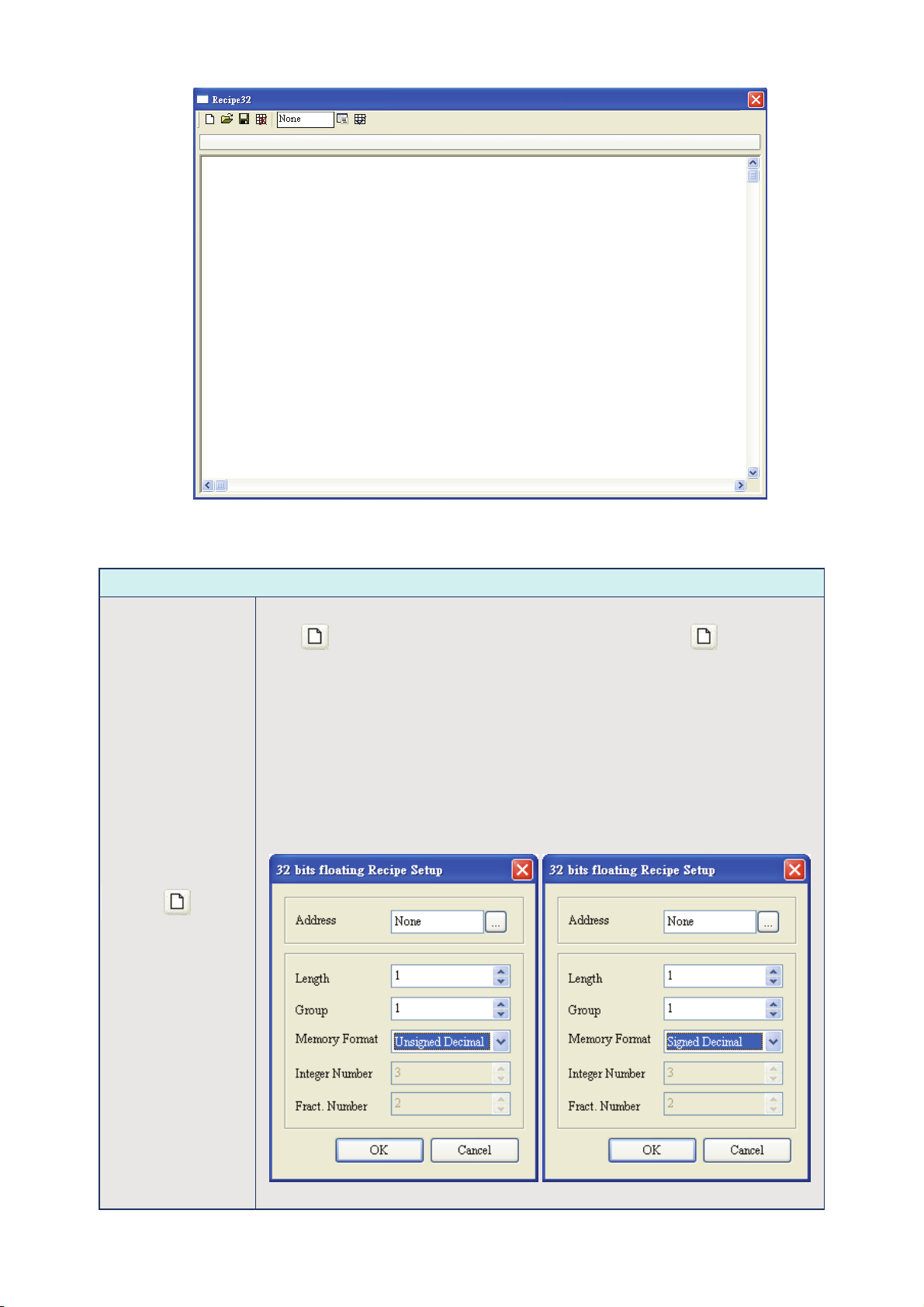
Chapter 2 Creating and Editing Screens|ScrEdit Software User Manual
Fig. 2.8.19 32 bits Floating Recipe Setup dialog box
32 bits Floating Recipe Setup
New: Create a new 32 bits floating recipe file
Press to create a new 32 bits floating recipe. After clicking , a 32 bits
floating recipe setup dialog box will display and the user can use it to set the
settings of a 32 bits floating recipe. The user can determine the recipe storage
address, the length and group number of the recipe, the memory format, and the
integer & fractional digit number of the recipe data. There are three kinds of
memory format provided, including Unsigned Decimal, Signed Decimal and
Floating (Fig. 2.8.20, Fig. 2.8.21 and Fig. 2.8.22). Integer and fractional digit
number cannot be selected when the memory format is set to Unsigned Decimal
and Signed Decimal. These two options is only available when the memory format
is set to Floating. But the total of the Integer and fractional digit number cannot
exceed 7 digits. For the number of the 32 bits floating recipe, up to 255 recipes
can be set in a 32 bits floating recipe file.
Table 2.8.3 32 bits Floating Recipe Editing
Fig. 2.8.20 Fig. 2.8.21
2-72 Revision Apr. 30th, 2007, 2007PDD23000002
Page 84
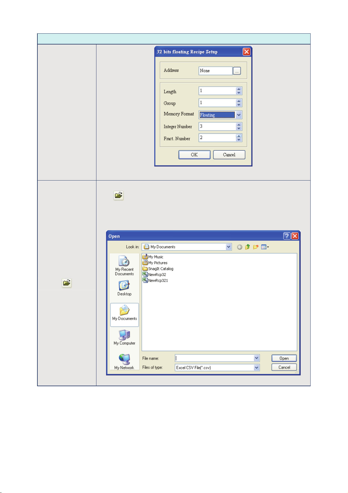
Chapter 2 Creating and Editing Screens|ScrEdit Software User Manual
32 bits Floating Recipe Setup
Open: Open a 32 bits floating recipe file
Fig. 2.8.22
Press to open a 32 bits floating recipe file. The file format can be Recipe 32
bits File (*.rcp) and Excel CSV File (*.csv) (Fig. 2.8.23). Please pay close attention
to the format of recipe file and make sure that the recipe file is a 16 bits data or a
32 bits data. Do not select the incorrect data format; otherwise the program will
not work normally.
Fig. 2.8.23
Revision Apr. 30th, 2007, 2007PDD23000002 2-73
Page 85
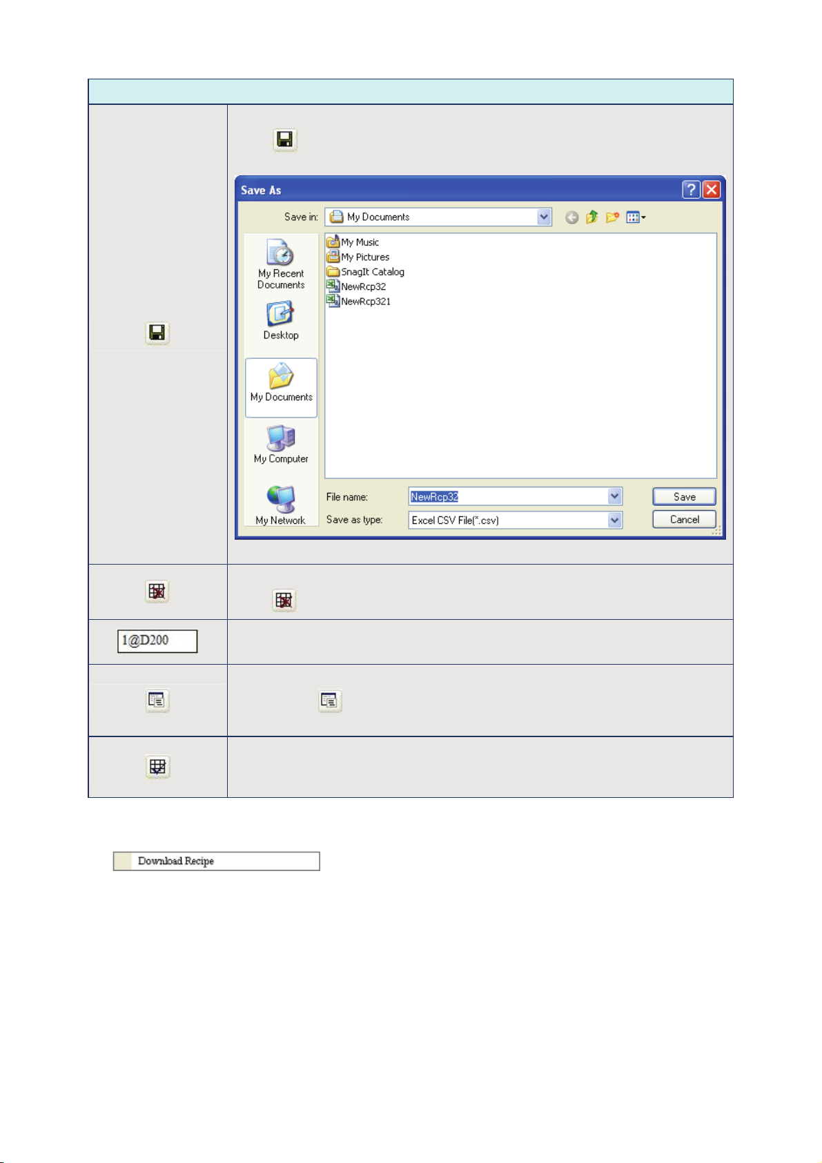
Chapter 2 Creating and Editing Screens|ScrEdit Software User Manual
32 bits Floating Recipe Setup
Save: Save a 32 bits floating recipe file
Press to save a 32 bits floating recipe file. The default file format of a 32 bits
floating recipe file is Excel CSV file (*.csv) (Fig. 2.8.24).
Fig. 2.8.24
Delete: Delete a 32 bits floating recipe
Download Recipe
Downloads recipe to HMI. It can save time when the user wants to download recipe date only. What the
user needs to do is to click Tools > Download Recipe and then the recipe data can be downloaded to
HMI. The general extension name of recipe file is rcp (Fig. 2.8.25).
Press to delete unnecessary 32 bits floating recipe.
Recipe Storage Address :
Display the storage address of a 32 bits floating recipe.
Setup: 32 bits floating recipe setup
When clicking , a 32 bits floating recipe setup dialog box will display and the
user can use it to change the settings of a 32 bits floating recipe.
Enable: Enable 32 bits floating recipe function
This function should be selected when the user wants to use 32 bits floating
recipe function.
2-74 Revision Apr. 30th, 2007, 2007PDD23000002
Page 86
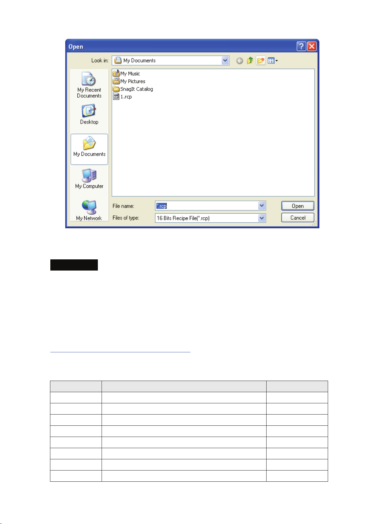
Chapter 2 Creating and Editing Screens|ScrEdit Software User Manual
Fig. 2.8.25 Download Recipe
Recipe Example
For recipe control, the user needs to use Recipe Control Register (RECR) and Designated Recipe
Group Number Register (RBIR) to control the read and write operation of recipe. The following
section only describes part of the introduction of recipe function. Please refer to Chapter 5 of Delta HMI
user manual for more detailed description of the control block.
This recipe example can be downloaded via the following link:
http://59.120.64.39:81/phpbb2/files/recipe_202.dop
The function and explanation of each WORD (register) of control block are listed below.
Word Number Register Number Example
0 Register for designating Screen Number (SNIR) Dn (D0)
1 Control Flag Register (CFR) Dn+1 (D1)
2 Curve Control Register (CUCR) Dn+2 (D2)
3 Register for Sampling History Buffer (HBSR) Dn+3 (D3)
4 Register for Clearing History Buffer (HBCR) Dn+4 (D4)
5 Recipe Control Register (RECR) Dn+5 (D5)
6 Register for designating Recipe Group Number (RBIR) Dn+6 (D6)
7 System Control Flag Register (SCFR) Dn+7 (D7)
Revision Apr. 30th, 2007, 2007PDD23000002 2-75
Page 87

Chapter 2 Creating and Editing Screens|ScrEdit Software User Manual
Recipe Control Register (RECR)
Bit Number
4~7 Reserved
8~15 Designate change recipe group number
0 Recipe number change
1
2
3 Recipe group number change
Read recipe (PLC → HMI)
Write recipe (HMI → PLC)
Function
Control Flag for Changing Recipe Number
There are two kinds of methods for changing and calling recipe number. One method is to use HMI
internal register, RCPNO directly. RCPNO is the internal system register used for designating recipe
number. The other method is to use Recipe Control Register (RECR) (Dn+5). When the user wants to
change HMI recipe number, i.e. RCPNO value through control block settings, first, it needs to write
recipe number (N) into Designated Recipe Number Register (RBIR) (Dn+6, please refer to the
explanation of Register for Designating Recipe Number (RBIR) in Chapter 5) and use this control flag
to trigger Bit 0 of Dn+5 to be ON. After setting, RCPNO will be changed to N automatically. This flag
needs be set to OFF and then ON if the user wants to trigger again.
Control Flag for Reading Recipe
The user can change the recipe value of PLC by triggering this control flag (Bit 1 is set to ON). Before
reading a recipe from PLC, the user should designate the recipe number (N) first (Please refer to the
section “Control Flag for Changing Recipe Number” in Chapter 5). Then, trigger this control flag to ON
(Bit 1 is set to ON). After setting, the recipe will be read from PLC and stored in designating area of
HMI. This flag needs be set to OFF and then ON if the user wants to trigger again.
Control Flag for Writing Recipe
Before writing a recipe to PLC, the user should designate the recipe number (N) first (Please refer to
the section “Control Flag for Changing Recipe Number” in Chapter 5). Then, trigger this control flag to
ON (Bit 2 is set to ON). After setting, the recipe will be written to PLC. This flag needs be set to OFF
and then ON if the user wants to trigger again.
Control Flag for Changing Recipe Group Number
There are two kinds of methods for changing and calling recipe group number. One method is to use
HMI internal register, RCPG directly. RCPG is the internal system register used for designating recipe
group number. The other method is to use Recipe Control Register (RECR) (Dn+5). When the user
wants to change HMI recipe group number through control block settings, first, it needs to write recipe
2-76 Revision Apr. 30th, 2007, 2007PDD23000002
Page 88

Chapter 2 Creating and Editing Screens|ScrEdit Software User Manual
group number (N) into the high byte of this control block and use this control flag to trigger, Dn+5 (Bit 3
is set to ON). After setting, RCPG will be changed to N automatically. This flag needs be set to OFF
and then ON if the user wants to trigger again.
Register for Designating Recipe Number (RBIR)
Word Function
0 Designate receipt number which the user wants to change
By writing recipe group number (N) into Designated Recipe Number Register (RBIR), RCPNO value
can be changed. The user can use the control flag for changing recipe number of Recipe Control
Register (RECR) to write recipe group number (N) into Designated Recipe Number Register (RBIR)
and change RCPNO value.
The following section will introduce how to use recipe. The example is named as recipe.dop and it is
saved in the Example folder under Screen Editor software installation directory.
Please click Tools > Recipe on menu bar and enter into Recipe Setup dialog box. In this example, the
Length is set to 6, Group is set to 7 and Address is set to Internal Memory $220. After complete the
above settings, your Screen will look like the Fig. 2.8.26 shown below.
Fig. 2.8.26 Recipe Setup dialog box
Revision Apr. 30th, 2007, 2007PDD23000002 2-77
Page 89

Chapter 2 Creating and Editing Screens|ScrEdit Software User Manual
Besides, in order to perform simulation operation more conveniently, the Address of Control Block is set to
Internal Memory $0. Your Screen will look like the Fig. 2.8.27 shown below.
Fig. 2.8.27 Control Block Settings of Configuration dialog box
2-78 Revision Apr. 30th, 2007, 2007PDD23000002
Page 90

Chapter 2 Creating and Editing Screens|ScrEdit Software User Manual
Fig. 2.8.28 Recipe Example
When the user select “Enable Recipe” option in Recipe Setup dialog box, there are RCP and RCPNO
two kinds of device types available for the user to select in Input dialog box (See the following Fig.
2.8.29). RCPNO is used to change the recipe group and RCP is used to store the recipe data. The
content of recipe register depends on the recipe data set by the user. The recipe changes, the recipe
register also changes. In this example, RCP0 ~ RCP17 are recipe registers and HMI will store the
recipe data set by the user in these recipe registers. If these registers have the corresponding recipe
set by the user, HMI will create recipe data into the internal recipe register automatically and select the
value in Input dialog box (See the following Fig. 2.8.29). $220 ~ $225 are the destination addresses
that are used to store the recipe data (Generally, the recipe data are set to be stored in the addresses
of external controller registers, but for the convenience of simulation operation, we set the recipe
storage address in the internal memory). $5 is used to display the status of Recipe Control Register
(RECR). Write Recipe ($5.2) button is used to execute write recipe operation. When this button is
pressed, HMI will write the recipe data from HMI recipe register RCP into the designated recipe storage
address ($220 ~ $225). Read Recipe ($5.1) button is used to execute read recipe operation. When this
button is pressed, HMI will read recipe data of recipe storage address ($220 ~ $225) back to HMI
recipe register RCP. $6 is RBIR, i.e. Designated Recipe Group Number Register and its function is the
same as the function of RCPNO. The difference between these two registers is that RCPNO is a fixed
address of HMI internal memory, but the address of RBIR can be changed according to the setting of
control block (See 2.8.27 on previous page).
Revision Apr. 30th, 2007, 2007PDD23000002 2-79
Page 91
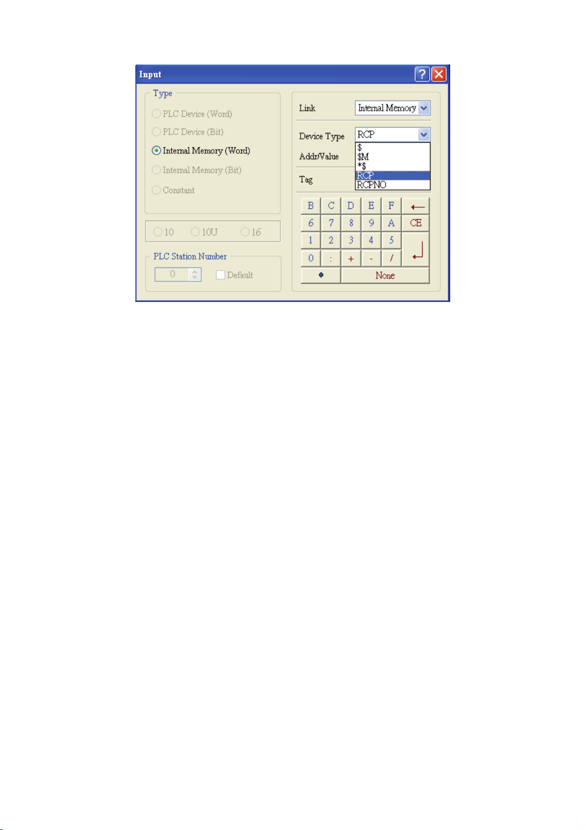
Chapter 2 Creating and Editing Screens|ScrEdit Software User Manual
Fig. 2.8.29 Input dialog box
The definition of Delta HMI recipe register RCP is described as follows. In Fig. 2.8.26, the length of example
recipe is set to 6 and the group of example recipe is set to 7. However, HMI actually create recipe registers
(RCP0 ~ RCP15) which the length is 6 but the group is 8. As the user can see in the Fig. 2.8.30, RCP0 ~
RCP5 is defined as recipe buffer area and RCP6 ~ RCP17 is the actual recipe storage area. The function of
recipe buffer area is for the user to put the desired change recipe data no matter execute Write Recipe or
Read Recipe operation. When the user want to change recipe data, the user have to use RCPNO or RBIR
these two registers. In the example shown in Fig. 2.8.30, when RCPNO is set to 2, it means that the using
recipe group is 2
nd
group. At this time, HMI will move the data of 2nd group and put them in the recipe buffer
area (RCP0 ~ RCP5). Besides using internal memory address (RCPG and RCPNO), the user also can enter
into Configuration dialog box and change the address value of recipe register directly. Since the example
control block address is set to $0, the user should use $6 RBIR, i.e. Designated Recipe Group Number
Register to designate recipe group and press Change Group ($5.0) button to designate the desired using
recipe group. When Write Recipe ($5.2) button is pressed, Write Recipe operation will be enabled. HMI will
write the recipe data from HMI recipe register RCP into the designated recipe storage address ($220 ~
$225). The example in Fig. 2.8.30 just displays the screen when HMI write the recipe data into $220 ~ $225.
Read Recipe ($5.1) button is used to execute read recipe operation. When this button is pressed, HMI will
read recipe data of recipe storage address ($220 ~ $225) back to HMI recipe register RCP.
2-80 Revision Apr. 30th, 2007, 2007PDD23000002
Page 92

Chapter 2 Creating and Editing Screens|ScrEdit Software User Manual
Recipe Buffer Area
Recipe Storage
Area
Fig. 2.8.30 Change recipe group
32 bits Recipe Example
This 32 bits recipe example can be downloaded via the following link:
http://59.120.64.39:81/phpbb2/files/32bit_recipe.dop
For the convenience of the user and enhance the flexibility of Delta HMI product on application, not
only the existing recipe function, the advanced 32 bits recipe function is also provided. The user can
manage the recipe data more flexibly and use this function on high precision controller and industry, e.g.
CNC controller, etc.
Besides inputting 32 bits recipe data, the 32 bits floating recipe function also allows the user to save
Double Word value. But the best advantage is that it makes recipe editing to be easier and more
flexible. The existing recipe function is a two-dimensional matrix. It means the user can set one recipe
length and one recipe group to create one recipe data in a project only. It is not user-friendly when the
user wants to create one more recipe data in the same project. Therefore, we develop 32 bits floating
recipe function and it is designed for the user that needs to input two and more recipe data in a project
simultaneously. In other word, the 32 bits recipe function can become a three-dimensional matrix. So,
the settings of the 32 bits recipe function will be a little different that the existing recipe function.
Revision Apr. 30th, 2007, 2007PDD23000002 2-81
Page 93

Chapter 2 Creating and Editing Screens|ScrEdit Software User Manual
For recipe control, the user needs to use Recipe Control Register (RECR) and Designated Recipe
Group Number Register (RBIR) to control the read and write operation of recipe. The user can refer
to page 2-74 ~ page 2-79 for the introduction and example of recipe function. For more detailed
description of the control block, please refer to for Chapter 5 of Delta HMI user manual
The following section will introduce how to use 32 bits recipe function. The example is named as 32 bits
recipe.dop and it is saved in the Example folder under Screen Editor software installation directory.
Please click Tools > 32 bits Floating Recipe on menu bar and enter into 32 bits Recipe Setup dialog
box. In this example, you can see that two recipe data is set in different tab. One is B1-4x3 and the
other is B2-5x4. B1-4x3 indicates that its Length is set to 4 and its Group is set to 3. B2-5x4 indicates
that its Length is set to 5 and its Group is set to 4. The memory format of B1 recipe data is set to
Floating and the memory format of B2 recipe data is set to Unsigned Decimal. Please refer to Fig.
2.8.31 below and Fig. 2.8.32 shown on next page.
Fig. 2.8.31
2-82 Revision Apr. 30th, 2007, 2007PDD23000002
Page 94

Chapter 2 Creating and Editing Screens|ScrEdit Software User Manual
Fig. 2.8.32
In order to perform simulation operation more conveniently, the Address of Control Block is set to
Internal Memory $0. Please refer to Fig. 2.8.33 shown below.
Fig. 2.8.33
Fig. 2.8.34 is an example of starting screen. Besides using internal memory address (RCPG and
RCPNO), the user also can enter into Configuration dialog box and change the address value of recipe
register directly. No matter what kind of method is chosen, the user still needs to execute recipe read
and write operation via Control Block. Pressing Internal Memory button is to switch the recipe data by
using internal memory address and pressing Control Block button is to switch the recipe data through
the settings of the Control Block.
Revision Apr. 30th, 2007, 2007PDD23000002 2-83
Page 95

Chapter 2 Creating and Editing Screens|ScrEdit Software User Manual
Fig. 2.8.34
When Internal Memory button is pressed, HMI will enter intro the screen shown as Fig. 2.8.35. RCPG is
used to store the recipe data, RCPNO is used to change the recipe group and RCP0 ~ RCP15 are
recipe registers and HMI will store the recipe data set by the user in these recipe registers. $1000 ~
$1006 are the destination addresses that are used to store the recipe data (Generally, the recipe data
are set to be stored in the addresses of external controller registers, but for the convenience of
simulation operation, we set the recipe storage address in the internal memory). Because this example
uses 32 bits recipe data, each recipe data will occupy two WORD registers. It means that the recipe
storage addresses will be $1000, $1002, $1004 and $1006. $5 in green is used to display the status of
Recipe Control Register (RECR). Recipe Write ($5.2) button is used to execute recipe write operation.
When this button is pressed, HMI will write the recipe data from HMI recipe register RCP into the
designated recipe storage address ($1000 ~ $1006). Recipe Read ($5.1) button is used to execute
recipe read operation. When this button is pressed, HMI will read recipe data of recipe storage address
($1000 ~ $1006) back to HMI recipe register RCP. Main button is used to return to the screen shown
as Fig. 2.8.34.
When the value of RCPG is equal to 0, it means that the display data of RCP register is a 16 bits recipe
data. Since there is no 16 bits recipe data set in this example, the value of RCPG will display 0 only
and the display of HMI will be shown as Fig. 2.8.35 on next page. When the value of RCPG is equal to
1, it means that the RCP register will display the B1 recipe data (Fig. 2.8.31) and the display of HMI
screen will be shown as Fig. 2.8.36 on next page.
2-84 Revision Apr. 30th, 2007, 2007PDD23000002
Page 96
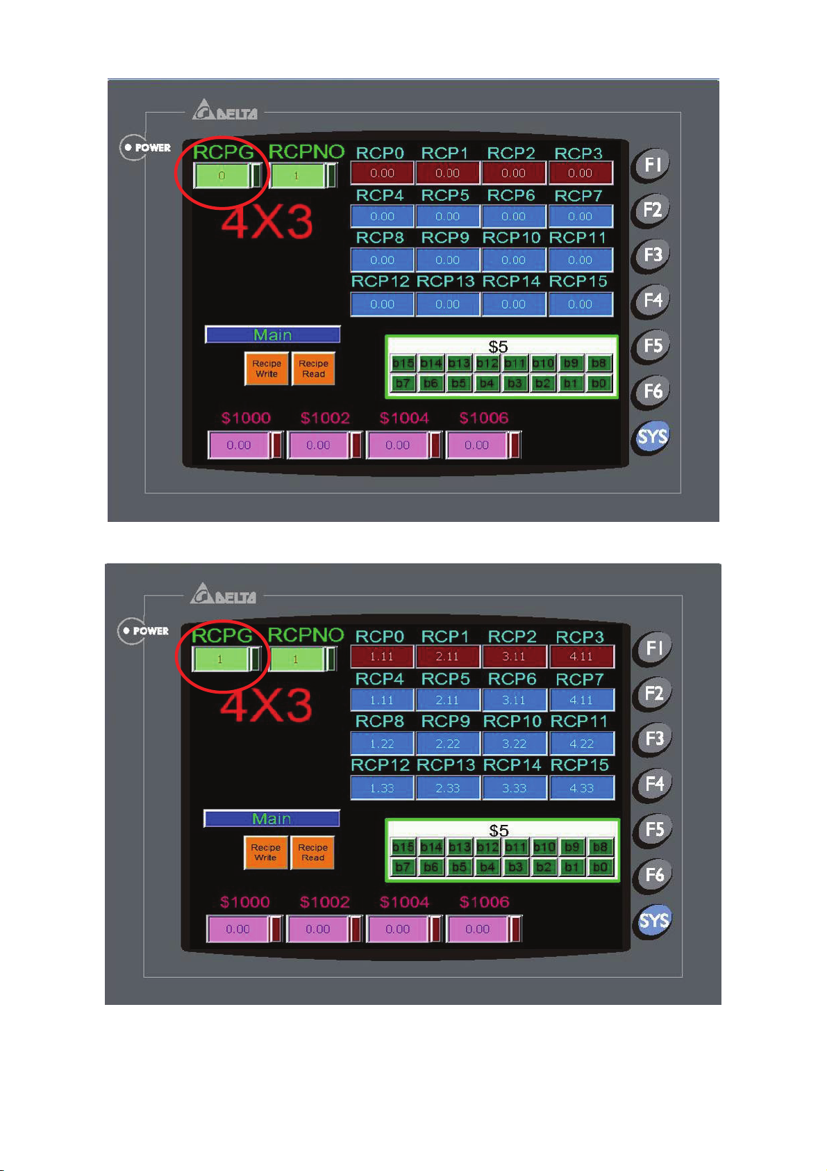
Chapter 2 Creating and Editing Screens|ScrEdit Software User Manual
Fig. 2.8.35
Fig. 2.8.36
Revision Apr. 30th, 2007, 2007PDD23000002 2-85
Page 97
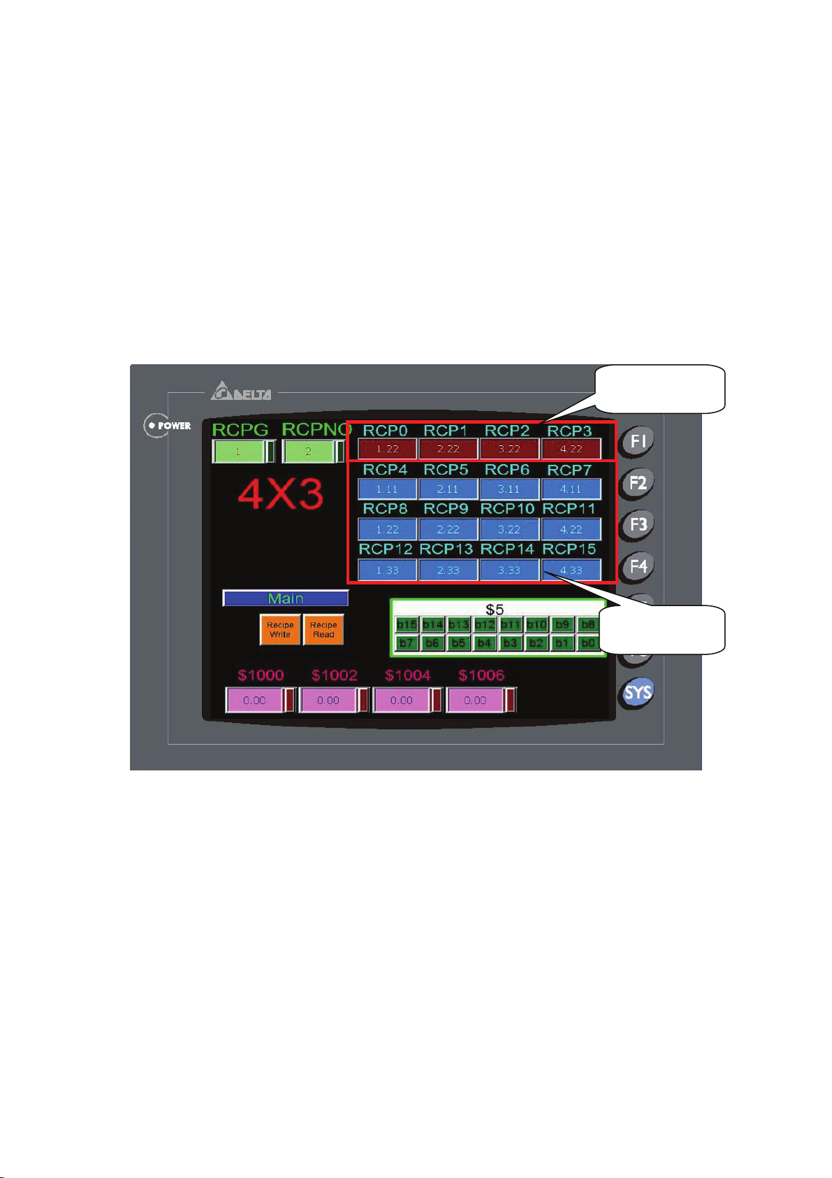
Chapter 2 Creating and Editing Screens|ScrEdit Software User Manual
A
A
The definition of Delta HMI recipe register RCP is described as follows. In Fig. 2.8.31, the length of B1
recipe data is set to 4 and the group of B1 recipe data is set to 3. However, HMI actually create recipe
registers (RCP0 ~ RCP15) which the length is 4 but the group is 4. As the user can see in the Fig.
2.8.37 below, RCP0 ~ RCP3 is defined as recipe buffer area and RCP4 ~ RCP15 is the actual recipe
storage area. The function of recipe buffer area is for the user to put the desired change recipe data no
matter execute Recipe Write or Recipe Read operation. When the user want to change recipe data, the
user have to use RCPNO or RBIR these two registers. In the example shown in Fig. 2.8.37 below,
when RCPNO is set to 2, it means that the using recipe group is 2
time, HMI will move the data of 2
nd
group of B1 recipe data and put them in the recipe buffer area
nd
group of B1 recipe data. At this
(RCP0 ~ RCP3).
Recipe Buffer
rea
Recipe Storage
rea
Fig. 2.8.37
As Fig. 2.8.38 shown on next page, when Recipe Write ($5.2) button is pressed, write recipe operation
will be enabled. HMI will write the recipe data from HMI recipe register RCP into the designated recipe
storage address. The example in Fig. 2.8.38 just displays the screen when HMI write the recipe data
into $1000 ~ $1006. Recipe Read ($5.1) button is used to execute recipe read operation. When this
button is pressed, HMI will read recipe data of recipe storage address ($1000 ~ $1006) back to HMI
recipe register RCP.
2-86 Revision Apr. 30th, 2007, 2007PDD23000002
Page 98
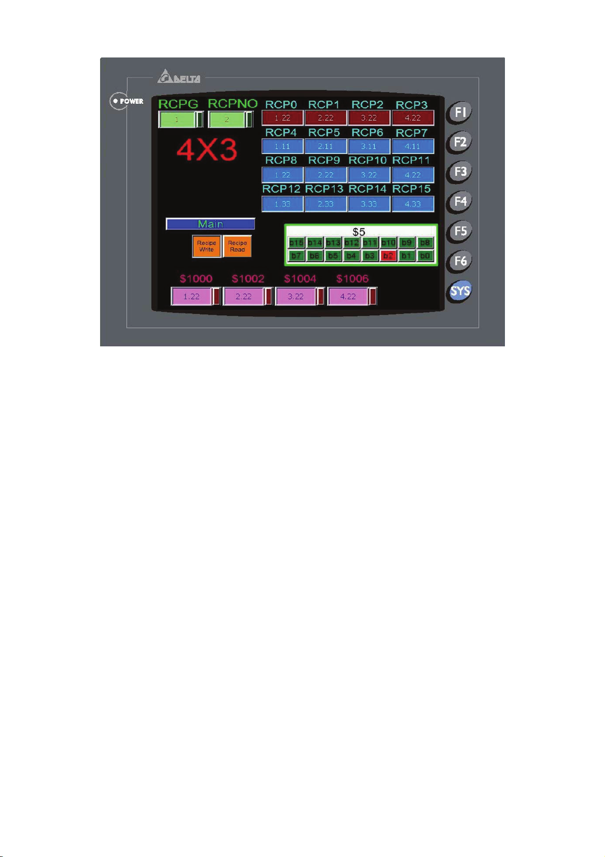
Chapter 2 Creating and Editing Screens|ScrEdit Software User Manual
Fig. 2.8.38
Besides using internal memory address (RCPG and RCPNO), the user also can enter into
Configuration dialog box and change the address value of recipe register directly. In Fig. 2.8.34,
pressing Control Block button is to switch the recipe data through the settings of the Control Block and
the example display will be shown as Fig, 2.8.39. In Fig. 2.8.39, $500 is used to set the desired change
recipe group number. But there is a After Execute Macro set in this register. The macro explanation is
described as follows:
SWAP($501, $500, 1) Exchange the high and low byte of $500 and store the result in
$501
$5 = $501 Move the value of $501 to $5
Since the example control block address is set to $0, $5 is set to the Recipe Control Register (RECR )
and bit 8 ~bit 15 is defined and used for setting recipe group number. There, the user should set the
designated recipe group, exchange the high and low byte and move the value to $5. After recipe group
number is set, press Block Change ($5.3) button to change recipe group. After the recipe group is
changed, the user should use $6 RBIR, i.e. Designated Recipe Group Number Register to designate
recipe group and press Change Group ($5.0) button to designate the desired using recipe group. When
Recipe Write ($5.2) button is pressed, recipe write operation will be enabled. HMI will write the recipe
data from HMI recipe register RCP into the designated recipe storage address ($1000 ~ $1006). The
example in Fig. 2.8.39 just displays the screen when HMI write the recipe data into $1000 ~ $1006.
Recipe Read ($5.1) button is used to execute read recipe operation. When this button is pressed, HMI
will read recipe data of recipe storage address ($1000 ~ $1006) back to HMI recipe register RCP
Revision Apr. 30th, 2007, 2007PDD23000002 2-87
Page 99
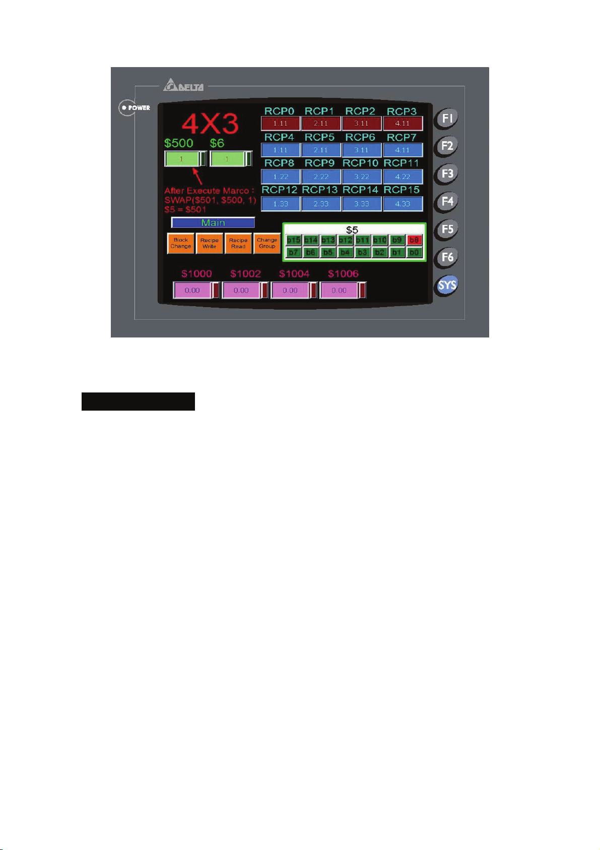
Chapter 2 Creating and Editing Screens|ScrEdit Software User Manual
Fig. 2.8.39
Recipe CSV File Editing
There are two recipe file types provided in Delta DOP series HMI, one is 16bits recipe file (*.rcp) that
only can be edited in ScrEdit software environment and the other is 32 bits recipe file (*.csv) that can
be opened and edited in Windows® Excel environment. The following section will describe how to edit
a Excel CSV File (*.csv) in Microsoft Excel. The definition of CSV file of general recipe and 32 bits
recipe file are not the same. Both of them will be introduced in the following.
General Recipe Example
The layout of its csv file is shown as Fig. 2.8.40 on next page. The first row shows the length and group
number. The other data are the actual recipe value.
2-88 Revision Apr. 30th, 2007, 2007PDD23000002
Page 100
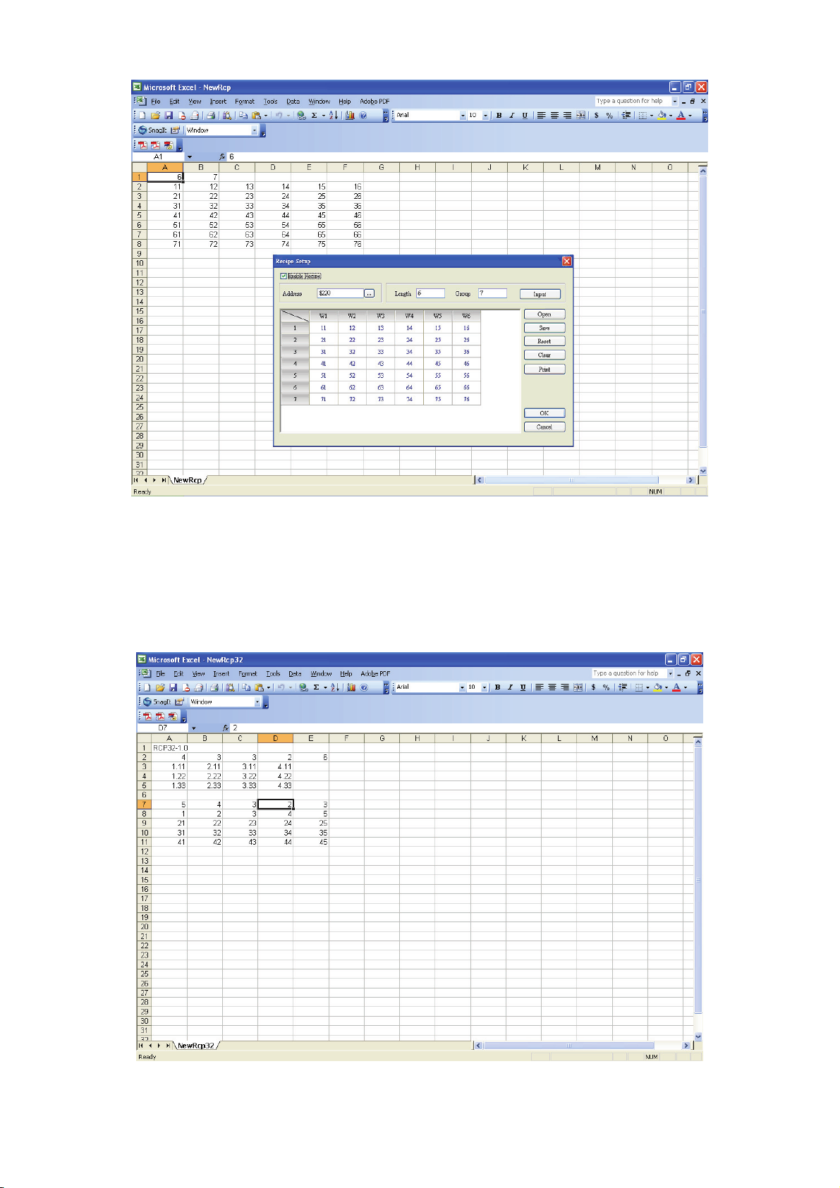
Chapter 2 Creating and Editing Screens|ScrEdit Software User Manual
Fig. 2.8.40
32 bits Recipe Example
The layout of its csv file is shown as Fig. 2.8.41 below. The first row shows RCP32-1.0. This is the
version of this 32 bits recipe and the user should not change it.
Fig. 2.8.41
Revision Apr. 30th, 2007, 2007PDD23000002 2-89
 Loading...