

Page 1
INSTRUCTIONS
30" Fence and Rail System
(Model 36-648)
PART NO. 912859 - 10-20-03
Copyright © 2003 Delta Machinery
To learn more about DELTA MACHINERY
visit our website at: www.deltamachinery.com.
For Parts, Service, Warranty or other Assistance,
please call
1-800-223-7278 (In Canada call 1-800-463-3582).
SHOWN ASSEMBLED
TO MODEL 36-649
Page 2
2
Indicates an imminently hazardous situation which, if not avoided, will result in death or serious injury.
Indicates a potentially hazardous situation which, if not avoided, could result in death or serious injury.
Indicates a potentially hazardous situation which, if not avoided, may result in minor or moderate injury.
Used without the safety alert symbol indicates potentially hazardous situation which, if not avoided, may
result in property damage.
This manual contains information that is important for you to know and understand. This information relates to protecting YOUR SAFETY and PREVENTING EQUIPMENT PROBLEMS. To help you recognize this information, we use the
symbols to the right. Please read the manual and pay attention to these sections.
SAFETY GUIDELINES - DEFINITIONS
INTRODUCTION
The Delta Model 36-648 30" Fence and Rail System can be assembled to the Delta Model 36-649 10" Professional
Table Saw. The Model 36-648 is a heavy duty fence that has a rip capacity of 30" to the right side of the blade.
NOTICE: THE MANUAL COVER PHOTO ILLUSTRATES THE CURRENT
PRODUCTION MODEL. ALL OTHER ILLUSTRATIONS ARE REPRESENTATIVE
ONLY AND MAY NOT DEPICT THE ACTUAL COLOR, LABELING OR
ACCESSORIES AND MAY BE INTENDED TO ILLUSTRATE TECHNIQUE ONLY.
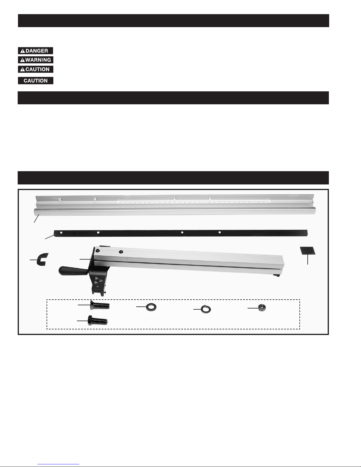
CARTON CONTENTS
Fig. 2
1. Front Guide Rail
2. Rear Rail
3. Guide Rail End Cap (2)
4. Fence
5. Fence End Cap
6. 3/8-16x1½" Flat Head Screw (4)
7. 3/8-16x1" Hex Head Screw (4)
8. 3/8" Flat Washer (8)
9. 3/8" Lockwasher (8)
10. 3/8-16 Hex Nut (8)
1
2
3
4
5
6
7
8
9
10
Page 3
3
ASSEMBLY
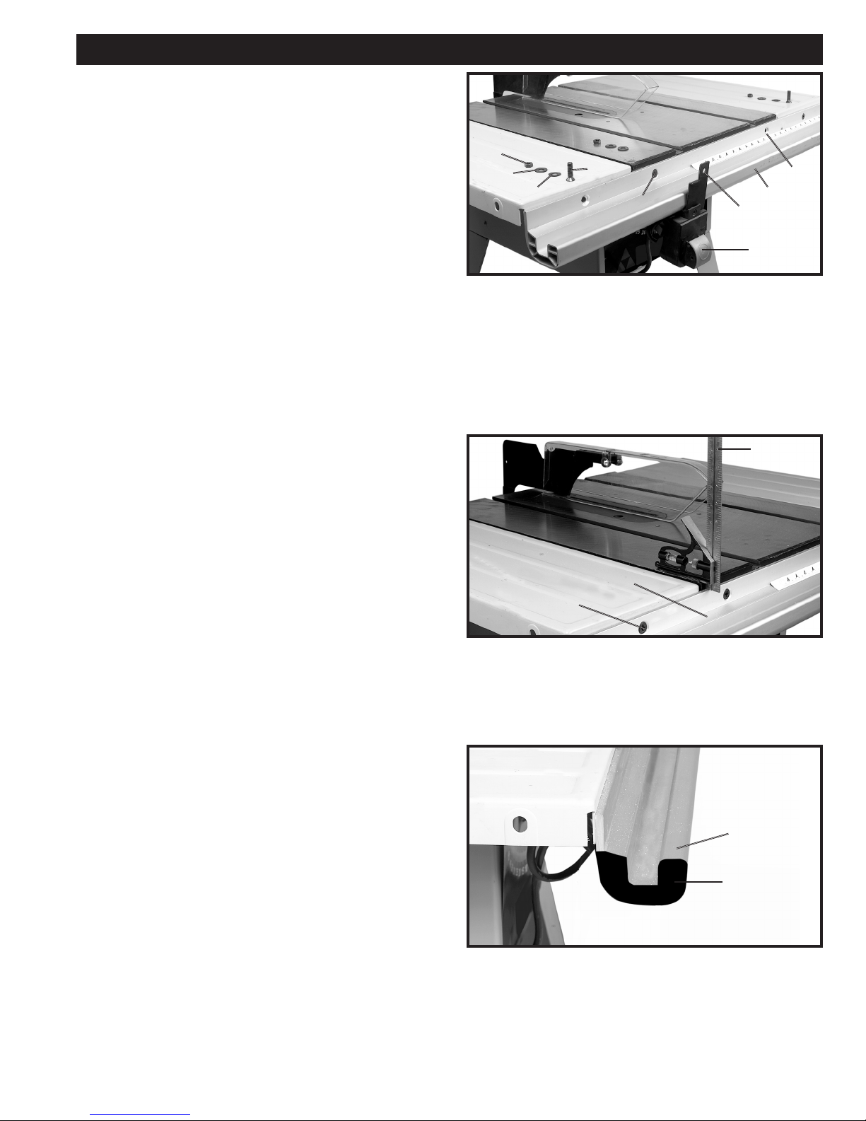
FRONT GUIDE RAIL AND
SWITCH ASSEMBLY
1. Loosely assemble front guide rail (A) Fig. 3, to the
front of the saw table. Align the two holes (B) and (C)
with the two holes in the saw table. Insert a 3/8-16x11/2" flat head screw (F) Fig. 3, through holes (B) and (C)
in the front guide rail (A) and the holes in the front of the
saw table. Place hole in switch bracket (E) Fig. 3, on
screw (B) located behind the inner lip of the saw table.
Place a 3/8" flat washer (G) and a 3/8 lockwasher (H),
onto the flat head screw (F). Thread a 3/8-16 hex nut (J),
onto the flat head screw (F). Repeat this process for the
remaining hole (C) in the guide rail and the saw table.
Fig. 3
J
H
G
F
B
E
D
A
C
2. Loosely fasten guide rail (A) Fig. 4, to the left and
right extension wings. Align the the hole (B) Fig. 4, in the
left side of the guide rail with the hole on the left
extension wing. Insert a 3/8-16x1-1/2" flat head screw
through the hole (B) in the front guide rail (A) and the hole
in the front of the left extension wing. Place a 3/8" flat
washer and a 3/8 lockwasher onto the flat head screw.
Thread a 3/8-16 hex nut onto the flat head screw.
Repeat this process for the remaining hole in the guide
rail and the right extension wing.
Fig. 4
F
A
B
3. Before tightening the hardware holding the guide rail
to the saw table, proceed as follows: Beginning at the
two sides of the saw table and using an adjustable
square (F) Fig. 4, or a ruler, check to make certain the
guide rail (A) is parallel with the saw table and extension
wings. Tighten all guide rail mounting hardware.
4. Insert end cap (G) Fig. 5, onto each end of the guide
rail (D) as shown. Using a block of wood and
hammer, gently tap end caps until they are completely
seated into each end of the guide rail. NOTE: Do not use
a hammer directly against the end caps, this could
cause damage to the aluminum rail.
Fig. 5
G
D
Page 4
4
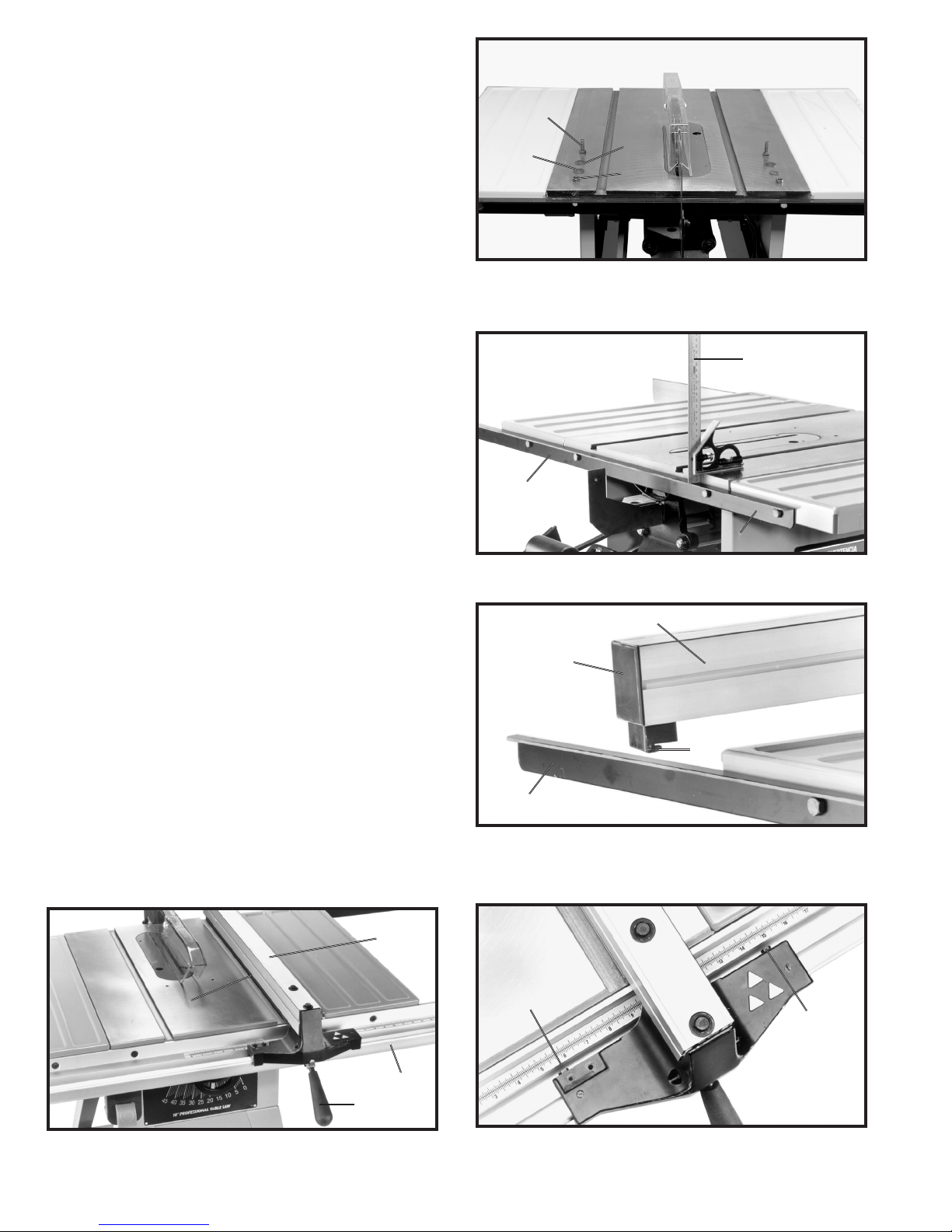
REAR RAIL
1. Align holes in saw table and extension wings with
four holes in rear guide rail (J) Fig. 6. NOTE: Flat edge of
rear guide rail (J) will face upward. Insert a 3/8-16x1" hex
head screw (A) Fig. 43, through hole in rear guide rail and
hole in saw table. Place a 3/8" flat washer (B) Fig. 6, and
a 3/8" lock washer (C), onto the hex head screw. Thread
a 3/8-16 hex nut (D), onto the hex head screw. Repeat
this process for the three remaining holes in the rear
guide rail and the saw table and extension wings.
Fig. 6
A
B
C
D
2. Before tightening mounting hardware, using an
adjustable square (F) Fig. 7, or a ruler, check to make
certain the rear guide rail (J) is parallel with the saw table
and extension tables.
Fig. 7
F
J
J
RIP FENCE TO GUIDE RAILS
1. Insert end cap (A) Fig. 8, into back of rip fence (B).
2. With the fence handle (A) Fig. 9, in the raised
position, place the rip fence (B) onto the rear guide rail
(C) so the hooked end (D) Fig. 8, fits over the top ledge
of the guide rail as shown.
Fig. 8
B
A
C
D
Fig. 9
B
C
A
L
3. Lower the front of rip fence (B) Fig. 9, onto the front
guide rail (L).
4. Lock the rip fence (B) Fig. 9, on the guide rails by
pushing down handle (A).
5. Slide rip fence (B) Fig. 9, against one edge of the
miter gage slot (C) as shown. Clamp the fence onto the
guide rail by pushing down on lock handle (A). The edge
of the fence (B) Fig. 9, should line up so it is parallel with
the edge of the miter gage slot. If an adjustment is
necessary, pull up on lock handle (A) to loosen fence,
tighten or loosen either of two screws (D)
Fig. 10, as necessary until rip fence (B) Fig. 9, lines up
with the miter gage slot. NOTE: Cursor has been
removed for clarity.
Fig. 10
D
D
Page 5

5
6. Once the rip fence is aligned with the miter gage
slot, raise the saw blade (E) Fig. 11, to its highest
position, as shown. Slide rip fence (B) against the saw
blade (E) and lock the fence in that position by pushing
down on handle (A).
Fig. 11
A
B
E
7. The cursor witness line (F) Fig. 12, should line up
with the “zero” mark on scale (G). If the witness line does
not line up with the “zero” line on the scale, loosen two
screws (H) and adjust cursor (K).
Fig. 12
H
K
F
G
ADJUSTMENTS
RIP FENCE
To move the rip fence, raise the lock handle (A) Fig. 13,
as far as it will go and move the fence to the desired
position on the table. When the lock handle (A) Fig. 13,
is pushed down, clamping action on the rip fence (B)
should be adequate. However, if the clamping action is
too loose or too tight, an adjustment can be made by
equally tightening or loosening two screws (C) as
necessary, see the section “RIP FENCE TO GUIDE
RAIL” for detailed instructions. NOTE: It will be
necessary to remove the cursor (D) Fig. 15, to make this
adjustment.
THE BLADE FLANGE (FOR DELTA
TABLE SAW MODEL 36-649) IS SET PARALLEL TO
THE MITER GAGE SLOT AT THE FACTORY AND THE
RIP FENCE MUST BE PROPERLY ALIGNED TO THE
MITER GAGE SLOT IN ORDER TO PREVENT
“KICKBACK” WHEN RIPPING.
Fig. 13
C
C
F
B
A
THE RIP FENCE MUST BE
PERPENDICULAR TO AND LEVEL WITH THE SAW
TABLE.
The rip fence can be used on either side of the saw blade. The most common location is on the right side and is guided
by means of guide rails which are fastened to the front and rear of the table.
Page 6

6
Fig. 14
K
K
A
G
B
4. Using a square (G) Fig. 14, check to see if the rip
fence (B) is perpendicular to the saw table and that the
rip fence body is level with the saw table. If an
adjustment is necessary, tighten or loosen either of two
screws (K), until the fence is perpendicular and level with
the saw table.
5. Depending on the type of saw blade being used, the
cursor (D) Fig. 15, may need adjustment to compensate
for the blade thickness.To adjust the cursor, make a test
cut on a piece of lumber and measure the finished cut,
or you can place the rip fence against the blade as
shown earlier in the manual. If a minor adjustment is
necessary, loosen two screws (E) Fig. 15, and move the
cursor (D) as necessary.
Fig. 15
D
E
E
OPERATIONS
Common sawing operations include ripping and crosscutting plus a few other standard operations of a fundamental
nature. As with all power machines, there is a certain amount of hazard involved with the operation and use of the
machine. Using the machine with the respect and caution demanded as far as safety precautions are concerned, will
considerably lessen the possibility of personal injury. However, if normal safety precautions are overlooked or completely
ignored, personal injury to the operator can result. The following information describes the safe and proper method for
performing the most common sawing operations. NOTICE: THE PICTURES IN THIS SECTION ARE INTENDED TO
ILLUSTRATE TECHNIQUE ONLY.
THE USE OF ATTACHMENTS AND ACCESSORIES NOT RECOMMENDED BY DELTA MAY RESULT
IN THE RISK OF INJURY TO PERSONS.
NEVER USE THE FENCE AS A CUT-OFF
GAGE WHEN CROSS-CUTTING.
When using the block (B) Fig. 16, as a cutoff gage, it is very important that the rear end of the block
be positioned so the work piece is clear of the block
before it enters the blade.
When cross-cutting a number of pieces to the same
length, a block of wood (B), can be clamped to the fence
and used as a cut-off gage as shown in Fig. 16. It is
important that this block of wood always be positioned in
front of the saw blade as shown. Once the cut-off length
is determined, secure the fence and use the miter gage
to feed the work into the cut.
This block of wood allows the cut-off piece to move
freely along the table surface without binding between
the fence and the saw blade, thereby lessening the
possibility of kickback and injury to the operator.
CUT-OFF
Fig. 16
B
Page 7

7
RIPPING
A RIP FENCE SHOULD ALWAYS BE
USED FOR RIPPING OPERATIONS. NEVER
PERFORM A RIPPING OPERATION FREE-HAND.
Ripping is the operation of making a lengthwise cut
through a board, as shown in Fig. 17, and the rip fence
(A) is used to position and guide the work. One edge of
the work rides against the rip fence while the flat side of
the board rests on the table. Since the work is pushed
along the fence, it must have a straight edge and make
solid contact with the table. The saw guard must be
used. The guard has anti-kickback fingers to prevent
wood kickback, and a splitter to prevent the wood kerf
from closing and binding the blade.
Start the motor and advance the work holding it down
and against the fence. Never stand in the line of the saw
cut when ripping. Hold the work with both hands and
push it along the fence and into the saw blade as shown
in Fig. 17. The work can then be fed through the saw
blade with one or two hands. After the work is beyond
the saw blade and anti-kickback fingers, the hand is
removed from the work. When this is done the work will
either stay on the table, tilt up slightly and be caught by
the rear end of the guard or slide off the table to the floor.
Alternately, the feed can continue to the end of the table,
after which the work is lifted and brought back along the
outside edge of the fence. The cut-off stock remains on
the table and is not touched with the hands until the saw
blade is stopped, unless it is a large piece allowing safe
removal. When ripping boards longer than three feet, it is
recommended that a work support be used at the rear of
the saw to keep the workpiece from falling off the saw
table.
If the ripped work is less than 4 inches
wide, a push stick should always be used to complete
the feed, as shown in Fig. 18. The push stick can easily
be made from scrap material as explained in the section
“CONSTRUCTING A PUSH STICK.” When ripping
material under 2 inches in width, a flat pushboard is a
valuable accessory since ordinary push sticks may
interfere with the blade guard. The flat pushboard can be
made as shown in Fig. 19.
Fig. 17
Fig. 18
A
Fig. 19
USING AUXILIARY WOOD
FACING ON RIP FENCE
It is necessary when performing special
operations such as moulding to add wood facing (A) Fig.
20, to one or both sides of the rip fence, as shown. The
wood facing is attached to the fence with two clamps (B).
3/4 inch stock is suitable for most work although an
occasional job may require 1 inch facing.
A wood facing should be used when ripping thin material
such as paneling to prevent the material from catching
between the bottom of the rip fence and the saw table
surface.
Fig. 20
A
B
B
Page 8

8
MAINTENANCE
FENCE LUBRICATION
1. Apply paste wax to fence and guide tube sliding surfaces weekly.
2. Apply grease to cam lock (A) Fig. 21, and cam foot (B)
occasionally to prevent wear.
Fig. 21
A
B
CONSTRUCTING A
FEATHERBOARD
Fig. 23, illustrates dimensions for making a typical
featherboard. The material which the featherboard is
constructed of, should be a straight piece of wood that
is free of knots and cracks. Featherboards are used to
keep the work in contact with the fence and table and
help prevent kickbacks. Clamp the featherboards to the
fence and table so that the leading edge of the
featherboards will support the workpiece until the cut is
completed.
Use featherboar
ds for all non “thrusawing” operations where the guard and spreader
assembly cannot be used (see Fig. 22). Always replace
the guard and spreader assembly when the non thrusawing operation is completed.
Fig. 23
Fig. 22
FEATHERBOARDS AND PUSH STICKS
Page 9

9
PUSH STICK
MAKE FROM 1/2" OR 3/4"
WOOD OR THICKNESS
LESS THAN WIDTH OF
MAT’L. TO BE CUT
CUT OFF HERE TO
PUSH 1/4" WOOD
CUT OFF HERE TO
PUSH 1/2" WOOD
NOTCH TO HELP
PREVENT HAND
FROM SLIPPING
1/2" SQUARES
CONSTRUCTING A PUSH STICK
When ripping work less than 4 inches wide, a push stick should be used to complete the feed and could be made from
scrap material by following the pattern shown.
Page 10

10
NOTES
Page 11

11
PARTS, SERVICE OR WARRANTY ASSISTANCE
All Delta Machines and accessories are manufactured to high quality standards and are serviced by a network
of Porter-Cable • Delta Factory Service Centers and Delta Authorized Service Stations. To obtain additional
information regarding your Delta quality product or to obtain parts, service, warranty assistance, or the location
of the nearest service outlet, please call 1-800-223-7278 (In Canada call 1-800-463-3582).
A complete line of accessories is available from your Delta Supplier, Porter-Cable • Delta Factory Service Centers,
and Delta Authorized Service Stations. Please visit our Web Site
www.deltamachinery.com for a catalog or
for the name of your nearest supplier.
Since accessories other than those offered by Delta have not been tested with this
product, use of such accessories could be hazardous. For
safest operation, only Delta
recommended accessories should be used with this product.
Two Year Limited New Product Warranty
Delta will repair or replace, at its expense and at its option, any new Delta machine, machine part, or machine accessory
which in normal use has proven to be defective in workmanship or material, provided that the customer returns the product
prepaid to a Delta factory service center or authorized service station with proof of purchase of the product within two
years and provides Delta with reasonable opportunity to verify the alleged defect by inspection. For all refurbished Delta
product, the warranty period is 180 days. Delta may require that electric motors be returned prepaid to a motor
manufacturer’s authorized station for inspection and repair or replacement. Delta will not be responsible for any asserted
defect which has resulted from normal wear, misuse, abuse or repair or alteration made or specifically authorized by
anyone other than an authorized Delta service facility or representative. Under no circumstances will Delta be liable for
incidental or consequential damages resulting from defective products. This warranty is Delta’s sole warranty and sets
forth the customer’s exclusive remedy, with respect to defective products; all other warranties, express or implied, whether
of merchantability, fitness for purpose, or otherwise, are expressly disclaimed by Delta.
ACCESSORIES
Page 12

The following are trademarks of PORTER-CABLE·DELTA (Las siguientes son marcas registradas de PORTER-CABLE S.A.): Auto-Set®,
BAMMER®, B.O.S.S.®, Builder’s Saw®, Contractor’s Saw®, Contractor’s Saw II™, Delta®, DELTACRAFT®, DELTAGRAM™, Delta Series
2000™, DURATRONIC™, Emc²™, FLEX®, Flying Chips™, FRAME SAW®, Homecraft®, INNOVATION THAT WORKS®, Jet-Lock®,
JETSTREAM®, ‘kickstand®, LASERLOC®, MICRO-SET®, Micro-Set®, MIDI LATHE®, MORTEN™, NETWORK™, OMNIJIG®, POCKET
CUTTER®, PORTA-BAND®, PORTA-PLANE®, PORTER-CABLE®&(design), PORTER-CABLE®PROFESSIONAL POWER TOOLS, Posi-Matic®,
Q-3®&(design), QUICKSAND®&(design), QUICKSET™, QUICKSET II®, QUICKSET PLUS™, RIPTIDE™&(design), SAFE GUARD II®, SAFELOC®, Sanding Center®, SANDTRAP®&(design), SAW BOSS®, Sawbuck™, Sidekick®, SPEED-BLOC®, SPEEDMATIC®, SPEEDTRONIC®,
STAIR EASE®, The American Woodshop®&(design), The Lumber Company®&(design), THE PROFESSIONAL EDGE®, THE PROFESSIONAL
SELECT®, THIN-LINE™, TIGER®, TIGER CUB®, TIGER SAW®, TORQBUSTER®, TORQ-BUSTER®, TRU-MATCH™, TWIN-LITE®,
UNIGUARD®, Unifence®, UNIFEEDER™, Unihead®, Uniplane™, Unirip®, Unisaw®, Univise®, Versa-Feeder®, VERSA-PLANE®, WHISPER
SERIES®, WOODWORKER’S CHOICE™.
Trademarks noted with ™ and ® are registered in the United States Patent and Trademark Office and may also be registered in other
countries. Las Marcas Registradas con el signo de ™ y ® son registradas por la Oficina de Registros y Patentes de los Estados Unidos y
también pueden estar registradas en otros países.
PORTER-CABLE • DELTA SERVICE CENTERS
(CENTROS DE SERVICIO DE PORTER-CABLE
• DELTA)
Parts and Repair Service for Porter-Cable •Delta Machinery are Available at These Locations
(Obtenga Refaccion de Partes o Servicio para su Herramienta en los Siguientes Centros de Porter-Cable
•
Delta)
Authorized Service Stations are located in many large cities. Telephone 800-438-2486 or 731-541-6042 for assistance locating one.
Parts and accessories for Porter-Cable
·
Delta products should be obtained by contacting any Porter-Cable·Delta Distributor, Authorized
Service Center, or Porter-Cable
·
Delta Factory Service Center. If you do not have access to any of these, call 800-223-7278 and you will
be directed to the nearest Porter-Cable
·
Delta Factory Service Center. Las Estaciones de Servicio Autorizadas están ubicadas en muchas
grandes ciudades. Llame al 800-438-2486 ó al 731-541-6042 para obtener asistencia a fin de localizar una. Las piezas y los accesorios
para los productos Porter-Cable
·
Delta deben obtenerse poniéndose en contacto con cualquier distribuidor Porter-Cable·Delta, Centro
de Servicio Autorizado o Centro de Servicio de Fábrica Porter-Cable
·
Delta. Si no tiene acceso a ninguna de estas opciones, llame al
800-223-7278 y le dirigirán al Centro de Servicio de Fábrica Porter-Cable
·
Delta más cercano.
ARIZONA
Tempe 85282 (Phoenix)
2400 West Southern Avenue
Suite 105
Phone: (602) 437-1200
Fax: (602) 437-2200
CALIFORNIA
Ontario 91761 (Los Angeles)
3949A East Guasti Road
Phone: (909) 390-5555
Fax: (909) 390-5554
San Leandro 94577 (Oakland)
3039 Teagarden Street
Phone: (510) 357-9762
Fax: (510) 357-7939
COLORADO
Arvada 80003 (Denver)
8175 Sheridan Blvd., Unit S
Phone: (303) 487-1809
Fax: (303) 487-1868
FLORIDA
Davie 33314 (Miami)
4343 South State Rd. 7 (441)
Unit #107
Phone: (954) 321-6635
Fax: (954) 321-6638
Tampa 33609
4538 W. Kennedy Boulevard
Phone: (813) 877-9585
Fax: (813) 289-7948
GEORGIA
Forest Park 30297 (Atlanta)
5442 Frontage Road,
Suite 112
Phone: (404) 608-0006
Fax: (404) 608-1123
ILLINOIS
Addison 60101 (Chicago)
400 South Rohlwing Rd.
Phone: (630) 424-8805
Fax: (630) 424-8895
Woodridge 60517 (Chicago)
2033 West 75th Street
Phone: (630) 910-9200
Fax: (630) 910-0360
MARYLAND
Elkridge 21075 (Baltimore)
7397-102 Washington Blvd.
Phone: (410) 799-9394
Fax: (410) 799-9398
MASSACHUSETTS
Braintree 02185 (Boston)
719 Granite Street
Phone: (781) 848-9810
Fax: (781) 848-6759
Franklin 02038 (Boston)
Franklin Industrial Park
101E Constitution Blvd.
Phone: (508) 520-8802
Fax: (508) 528-8089
MICHIGAN
Madison Heights 48071 (Detroit)
30475 Stephenson Highway
Phone: (248) 597-5000
Fax: (248) 597-5004
MINNESOTA
Minneapolis 55429
5522 Lakeland Avenue North
Phone: (763) 561-9080
Fax: (763) 561-0653
MISSOURI
North Kansas City 64116
1141 Swift Avenue
Phone: (816) 221-2070
Fax: (816) 221-2897
St. Louis 63119
7574 Watson Road
Phone: (314) 968-8950
Fax: (314) 968-2790
NEW YORK
Flushing 11365-1595 (N.Y.C.)
175-25 Horace Harding Expwy.
Phone: (718) 225-2040
Fax: (718) 423-9619
NORTH CAROLINA
Charlotte 28270
9129 Monroe Road, Suite 115
Phone: (704) 841-1176
Fax: (704) 708-4625
OHIO
Columbus 43214
4560 Indianola Avenue
Phone: (614) 263-0929
Fax: (614) 263-1238
Cleveland 44125
8001 Sweet Valley Drive
Unit #19
Phone: (216) 447-9030
Fax: (216) 447-3097
OREGON
Portland 97230
4916 NE 122 nd Ave.
Phone: (503) 252-0107
Fax: (503) 252-2123
PENNSYLVANIA
Willow Grove 19090
520 North York Road
Phone: (215) 658-1430
Fax: (215) 658-1433
TEXAS
Carrollton 75006 (Dallas)
1300 Interstate 35 N, Suite 112
Phone: (972) 446-2996
Fax: (972) 446-8157
Houston 77038
4321 Sam Houston Parkway,
West
Suite 180
Phone: (281) 260-8887
Fax: (281) 260-9989
WASHINGTON
Auburn 98001(Seattle)
3320 West Valley HWY, North
Building D, Suite 111
Phone: (253) 333-8353
Fax: (253) 333-9613
Printed in U.S.A
CANADIAN PORTER-CABLE • DELTA SERVICE CENTERS
ALBERTA
Bay 6, 2520-23rd St. N.E.
Calgary, Alberta
T2E 8L2
Phone: (403) 735-6166
Fax: (403) 735-6144
BRITISH COLUMBIA
8520 Baxter Place
Burnaby, B.C.
V5A 4T8
Phone: (604) 420-0102
Fax: (604) 420-3522
MANITOBA
1699 Dublin Avenue
Winnipeg, Manitoba
R3H 0H2
Phone: (204) 633-9259
Fax: (204) 632-1976
ONTARIO
505 Southgate Drive
Guelph, Ontario
N1H 6M7
Phone: (519) 767-4132
Fax: (519) 767-4131
QUÉBEC
1515 ave.
St-Jean Baptiste, Suite 160
Québec, Québec
G2E 5E2
Phone: (418) 877-7112
Fax: (418) 877-7123
1447, Begin
St-Laurent, (Montréal),
Québec
H4R 1V8
Phone: (514) 336-8772
Fax: (514) 336-3505
 Loading...