

Page 1

10-INCH PORTABLE CONTRACTOR
TABLE SAW
SCIE SUR TABLE PORTABLE CONTRACTOR DE 10 PO
SIERRA DE MESA DE CONTRATISTA PORTÁTIL DE 10
PULGADAS
Français (36)
Español (70)
www.DeltaMachinery.com
Instruction Manual
To reduce the risk of serious injury, thoroughly read and comply with all warnings and instructions in this manual and on product.
KEEP THIS MANUAL NEAR YOUR PRODUCT FOR EASY REFERENCE AND TO INSTRUCT OTHERS
36-6022
Page 2

TABLE OF CONTENTS
FUNCTIONAL DESCRIPTION .................................................. 2
IMPORTANT SAFETY INSTRUCTIONS ................................... 3
SAFETY-SYMBOLS-DEFINITIONS .......................................... 3
GENERAL SAFETY RULES ...................................................... 3
PROPOSITION 65 WARNING ................................................... 4
TABLE SAW SAFETY RULES ................................................... 5
TERMINOLOGY ................................................................... 5
GENERAL POWER TOOL SAFETY..................................... 5
SAW BLADE GUARD, ANTI-KICKBACK PAWLS AND .......
RIVING KNIFE ASSEMBLY..................................................6
MAKING A PUSH STICK ..................................................... 6
KICKBACKS ........................................................................ 7
POWER CONNECTIONS .......................................................... 8
POWER SOURCE ............................................................... 8
EXTENSION CORDS ........................................................... 8
UNPACKING ..............................................................................9
PACKAGE CONTENTS .......................................................9
CONTENTS OF HARDWARE BAGS ................................. 10
ASSMEBLY ............................................................................... 10
ASSEMBLING UPPER STAND .......................................... 11
ASSEMBLING THE STAND ............................................... 12
WHEELS ............................................................................ 13
PEDAL ASSEMBLY ........................................................... 14
UPPER STAND ASSEMBLY .............................................. 16
ATTACH SAW TO STAND ASSEMBLY ..............................18
HEIGHT ADJUSTMENT KNOB INSTALLATION ............... 19
BLADE AND GUARDS ...................................................... 19
ATTACH THE BLADE ........................................................ 19
INSERT THROAT PLATE ...................................................21
ANTI-KICKBACKS PAWLS AND BLADE GUARD ............ 23
OUTFEED SUPPORT STOPS ........................................... 24
ONBOARD STORAGE ....................................................... 26
OPERATION ............................................................................. 27
TURNING THE SAW ON/OFF ........................................... 28
TRANSPORTING THE SAW .............................................. 28
MAKING CUTS ........................................................................ 29
RIP CUTS .......................................................................... 30
BEVEL RIPPING ................................................................ 30
CROSSCUTTING .............................................................. 31
BEVEL CROSSCUTTING .................................................. 31
MITER CUTS ..................................................................... 31
COMPOUND MITER CUTS............................................... 32
LARGE PANEL CUTS ........................................................ 32
NON-THROUGH CUTS ..................................................... 32
MAKING A NON-THROUGH CUT .................................... 32
MAKING A DADO CUT ..................................................... 33
CUTTING AIDS AND ACCESSORIES .................................... 33
PUSH STICK ..................................................................... 33
AUXILIARY MITER GAUGE FACING ................................. 34
PUSH BLOCK .................................................................... 34
FEATHERBOARD .............................................................. 35
CUT OFF GAUGE .............................................................. 35
JIGS ................................................................................... 35
MAKING ADJUSTMENTS ....................................................... 36
LEVELING THE THROAT PLATE ....................................... 36
SQUARING THE BLADE VERTICALLY TO THE TABLE ... 36
ADJUSTING THE BEVEL STOPS ..................................... 37
ADJUSTING THE BLADE HEIGHT.................................... 38
CHANGING THE BEVEL ................................................... 38
USING THE MITER GAUGE .............................................. 39
USING THE OUTFEED SUPPORT .................................... 39
USING THE RIGHT HAND TABLE EXTENSION ............... 40
RIP FENCE ADJUSTMENTS ............................................. 40
RIVING KNIFE POSITION AND ALIGNMENT ....................... 42
LOWERING RIVING KNIFE ............................................... 42
RIVING KNIFE ALIGNMENT .............................................. 43
MAINTENANCE ....................................................................... 45
TROUBLESHOOTING ............................................................. 45
ACCESSORIES ........................................................................ 45
WARRANTY ............................................................................. 46
FRENCH ................................................................................... 47
SPANISH ...................................................................................93
FUNCTIONAL DESCRIPTION
The DELTA® #36-6022 series 10-inch Contractor
Table Saw is designed for portability and high quality
performance. It includes: basic machine, sturdy tubular
steel stand, integral 2 1/2” dust chute, a T-squared fence
system, T-slot miter gauge, 15-amp motor, on/off switch,
cast aluminum table, extension wing, see-through blade
guard with anti-kickback fingers, and 10-inch carbide
blade.
NOTICE: The manual cover illustrates the current production model. All other illustrations contained in the manual are
representative only and may not be exact depictions of the actual labeling or accessories included. They are intended for
illustrative purposes only.
SPECIFICATIONS
Max depth of cut at 90 degrees: 3-1/2”
Max depth of cut at 45 degrees: 2-1/2”
Max rip to right of blade: 30”
Max rip to left of blade: 12”
Max width of dado: 13/16” x 8 dia.
MOTOR SPECIFICATIONS
Amps 15 Amps
VOLTAGE
2 3
120 Volts
Page 3

IMPORTANT SAFETY INSTRUCTIONS
CAREFULLY READ AND FOLLOW ALL WARNINGS AND INSTRUCTIONS ON YOUR
PRODUCT AND IN THIS MANUAL. SAVE THIS MANUAL. MAKE SURE ALL USERS ARE
FAMILIAR WITH ITS WARNINGS AND INSTRUCTIONS WHEN USING THE TOOL. Improper operation, maintenance
or modification of tools or equipment could result in serious injury and/or property damage.
SAFETY SYMBOLS- DEFINITIONS
This manual contains information that is important for you to know and understand. This information relates to protecting
YOUR SAFETY and PREVENTING EQUIPMENT PROBLEMS. To help you recognize this information, we use the
symbols below. Please read the manual and pay attention to these sections.
Indicates an imminently hazardous situation which, if not avoided, will result in death or serious injury.
Indicates a potentially hazardous situation which, if not avoided, could result in death or serious injury.
Indicates a potentially hazardous situation which, if not avoided, may result in minor or moderate injury.
Used without the safety alert symbol indicates potentially hazardous situation which, if not avoided, may
result in property damage.
GENERAL SAFETY RULES
FAILURE TO FOLLOW THESE RULES MAY RESULT IN SERIOUS PERSONAL INJURY.
• READ INSTRUCTION MANUAL AND KNOW
YOUR TOOL. Read and familiarize yourself with
the entire instruction manual. Learning the tool’s
proper applications, limitation, and specific potential
hazards will greatly minimize the possibility of
accidents and injury. Make sure all users are familiar
with its warnings and instructions before using.
• MAINTAIN TOOLS WITH CARE. Keep tools sharp
and clean for best and safest performance. Follow
instructions for lubricating and changing accessories.
• KEEP GUARDS AND SAFETY DEVICES IN PLACE
and working properly.
• CHECK TOOLS FOR DAMAGE. Before using,
and after tool or accessory has been dropped or
damaged, check guards and affected parts,
for alignment, breakage and any other condition
that may affect its operation to make sure tool will
operate properly and all parts will perform their
intended function. Do not use a damaged product.
A guard or any other part that is damaged should be
properly repaired or replaced using factory approved
service parts.
• NEVER STAND ON TOOL. Serious injury could
occur if the tool tips or if you unintentionally contact
the cutting surface.
• WEAR PROPER APPAREL. Do not wear loose
clothing, gloves, neckties, rings, bracelets, or other
jewelry which may get caught in moving parts.
Nonslip protective footwear is recommended. Wear
protective hair covering to contain long hair.
• WEAR PROPER EYE PROTECTION. All persons
in work area should wear safety glasses with side
shields. Everyday eye glasses with impact resistant
lenses are not safety glasses. Eye equipment should
comply with ANSI Z87.1 standards.
• WEAR PROPER HEARING PROTECTION. All
people in work area should wear proper hearing
protection consistent with noise levels and exposure.
Hearing equipment should comply with ANSI S3.19
standards.
• DUST PROTECTION. Use of power tools can
generate and/or disburse dust, which may cause
serious or permanent respiratory or other injury,
including silicosis (a serious lung disease), cancer,
and death. Direct particles away from face and body.
Always operate tool in a well-ventilated area and
provide for proper dust removal. Use dust collection
system whenever possible. Avoid breathing dust and
avoid prolonged contact with dust. Allowing dust to
get into your mouth or eyes, or lay on your skin may
promote absorption of harmful material. Use properly
fitting NIOSH/OSHA approved respiratory protection
appropriate for the dust exposure and wash exposed
areas with soap and water.
• LOCK TOOLS AND WORK AREA. Use padlocks,
and master switches, or remove and store starter
keys to prevent operation by children and other
unauthorized users.
• DO NOT USE OR STORE TOOL IN DANGEROUS
ENVIRONMENTS. Exposure to rain and damp or
wet locations can result in shock or electrocution,
or damage the tool. Do not operate electric tools
near flammable liquids or in gaseous or explosive
atmospheres. Motors and switches in these tools
may spark and ignite fumes.
• KEEP WORK AREA CLEAN AND WELL LIT.
Cluttered and poorly-lit work areas, surfaces and
benches can lead to accidents.
3
Page 4

GENERAL SAFETY RULES (CONTINUED)
• KEEP CHILDREN AND BYSTANDERS AWAY from
work area.
• USE RECOMMENDED ACCESSORIES. Consult
manual for recommended accessories. Use of
inappropriate accessories may cause personal injury
or property damage.
• DISCONNECT TOOL from power source before
servicing, adjusting or changing set-ups or blades,
bits, cutters and other accessories.
• TO REDUCE RISK OF ACCIDENTAL STARTING
make sure power switches are in “OFF” position
before plugging tool in.
• TO REDUCE THE RISK OF ELECTRIC SHOCK,
this equipment has a polarized plug (one blade is
wider than the other). This plug will fit in a polarized
outlet only one way. If the plug does not fit fully in the
outlet, reverse the plug. If it still does not fit, contact
a qualified electrician to install the proper outlet. Do
not change the plug in any way.
• DO NOT touch the plug’s metal prongs when
unplugging or plugging in the cord.
• USE PROPER EXTENSION CORD. If you use an
extension cord, make sure it is in good condition and
heavy enough to carry the current your product will
draw. An undersized cord will cause a drop in line
voltage, resulting in loss of power and overheating.
See Extension Cord Chart for correct size depending
on cord length and data plate ampere rating. If in
doubt, use the next smaller gauge number. The
smaller the gauge number, the heavier the cord.
When working outside, make sure the extension cord
is rated for outdoor use. Consult power connection
section of this manual for Extension Cord Chart and
power connection safety.
• DO NOT ABUSE POWER CORDS. NEVER yank
cord to disconnect from receptacle, crush cord, or
expose it to heat, oil or sharp objects.
• USE PROPER TOOL. Do not force tool to do a task
for which it was not designed.
• SECURE WORKPIECE. Use clamps or a vise to
hold the workpiece when practical. It is safer than
using your hands and frees both hands to operate
tool.
• REMOVE ADJUSTING KEYS AND WRENCHES.
Form habit of checking to see that all adjusting keys
and wrenches are removed before starting tool.
• STAY ALERT, WATCH WHAT YOU ARE DOING,
AND USE COMMON SENSE. Do not use power
tools when tired or under the influence of drugs,
alcohol, or medication. A moment of inattention while
operating power tools may result in injury.
• USE PROPER FEED DIRECTION. Feed workpiece
against the direction of rotation of the tool’s blade,
cutter, or abrasive surface. Feeding in the other
direction may cause the workpiece to be thrown at
high speed.
• DO NOT OVERREACH. Keep proper footing and
balance to maintain control.
• DO NOT FORCE TOOL OR WORKPIECE. Operate
tool at intended speed and feed rate for better and
safer operation.
• NEVER LEAVE TOOL RUNNING UNATTENDED.
TURN POWER OFF. Do not leave tool until it comes
to a complete stop. In the event of a power failure,
move switch to “OFF” position.
• SERVICE PARTS. Use only identical replacement
parts when servicing your tool.
PROPOSITION 65 WARNING:
Dust created by power sanding, sawing, grinding, drilling, and other construction activities may contain
chemicals known to the state of California to cause cancer, birth defects or other reproductive harm.
Some examples are:
– Lead from lead-based paints
– Crystalline silica from bricks and cement and other masonry products
– Asbestos dust
– Arsenic and chromium from chemically-treated lumber
• Your risk from these exposures varies depending on how often you do this type of work. To reduce your exposure to
these chemicals: work in a well-ventilated area and work with approved safety equipment, such as dust masks that
are specifically designed to filter out microscopic particles.
• Avoid prolonged contact with dust from power sanding, sawing, grinding, drilling, and other construction activities.
Wear protective clothing and wash exposed areas with soap and water
If you have any questions or concerns relative to the use of your tool or the contents of this manual, stop using the tool
and call DELTA® Customer Care at 1-800-223-7278.
SAVE THESE INSTRUCTIONS.
Refer to them often and use them to instruct others.
If tool is loaned to someone, also loan them these instructions.
4 5
Page 5

TABLE SAW SAFETY RULES
TERMINOLOGY
The following terms will be used throughout the manual and you should become familiar with them.
— Through-cut - any cut that completely cuts through
the workpiece.
— Non-through cut - any cut that does not completely
cut through the workpiece.
— Push stick - a wooden or plastic stick, usually
homemade, that is used to push a small workpiece
through the saw and keeps the operator’s hands
clear of the blade.
— Kickback - when the saw blade binds in the cut or
the workpiece binds between the blade and the
fence and the workpiece is thrust back toward the
FAILURE TO FOLLOW THESE RULES MAY RESULT IN SERIOUS PERSONAL INJURY.
• SEE GENERAL POWER TOOL SAFETY SECTION OF THIS MANUAL. Read entire instruction manual before
operating saw. Learning the saw’s proper applications, limitations, and specific potential hazards will greatly
minimize the possibility of accidents and injury. Make sure all users are familiar with its warnings and instructions
before using saw.
• SEE POWER CONNECTION SECTION OF THIS MANUAL for instructions and warnings regarding power
cords and connections.
operator.
— Freehand - cutting without the use of a miter gauge
or rip fence or any other means of guiding or holding
the workpiece other than the operator’s hand.
— Plunge cutting - blind cuts in the workpiece made
by either raising the blade through the workpiece or
lowering the workpiece down to the blade.
— Re-sawing - flipping the workpiece to complete a cut
the saw is not capable of making in one pass.
— Cove cutting - an operation where the work is fed at
an angle across the blade. (Also known as “coving”)
GENERAL POWER TOOL SAFETY
• AVOID KICKBACK. Pay particular attention to the
instructions (below) for reducing risk of kickback.
• OBTAIN ADVICE from your supervisor, instructor,
or another qualified person if you are not thoroughly
familiar with the operation of this machine.
Knowledge is safety.
• DRESS PROPERLY. Wear appropriate apparel, eye
protection, hearing protection and dust protection as
specified in the General Power Tool Safety Section of
this manual.
• PROPER ASSEMBLY. Do not operate this saw until
it is completely assembled and installed according to
the instructions.
• STABILITY. Make sure table saw is properly
assembled and located on a stable surface before
use to keep saw from moving during cut. Do not
attempt the subsitute a table or other surface for the
leg assembly.
• USE CORRECT BLADE AND RIVING KNIFE for the
intended operation. The blade must be installed so
the points of the teeth are pointing toward the front
of the saw. Do not use oversized blade or blade with
incorrect arbor opening. Always tighten the blade
arbor nut securely. Before use, inspect the blade for
cracks or missing teeth. Do not use a damaged or
dull blade. Always use blade within the thickness
range for which the riving knife is designed.
• USE PROPER THROAT PLATE. The proper throat
plate must be in place and properly secured at all
times to reduce the risk of a thrown workpiece and
possible injury.
• USE SAW BLADE GUARD, RIVING KNIFE AND
ANTI-KICKBACK PAWLS. Your saw is equipped
with a modular blade guard, riving knife and antikickback pawl assembly, each component of
which should be used for every possible operation,
including all through cuts. This assembly is
discussed in more detail below. Make sure
components are securely installed prior to operation.
• NEVER CUT METALS, CEMENT BOARD OR
MASONRY. Certain man-made materials have
special instructions for cutting on table saws. Follow
the manufacturer’s recommendations at all times.
• SUPPORT YOUR WORKPIECE based on its size
and the type of operation to be performed. Hold the
workpiece firmly against the fence and down against
the table surface. Do not leave a wide panel or long
board (or other large workpiece) unsupported – the
weight of the workpiece may causes it to shift on the
table resulting in loss of control.
• NEVER PERFORM LAYOUT, ASSEMBLY OR SETUP WORK ON THE TABLE/WORK AREA when the
saw is running.
• USE A PUSH STICK that is appropriate to the
application to push and hold down a workpiece
through the completion of the cut. A push stick is
a wooden or plastic stick, usually homemade, that
should be used whenever the size or shape of the
workpiece would cause you to place your hands
within 6 in. (152 mm) of the blade. Instructions for
making a push stick are included in this manual. A
push stick is also provided with this saw.
• NEVER Perform freehand cutting, plunge cutting,
re-sawing, or cove cutting.
• CHECK WORKPIECE AND SET-UP before each
operation. Knots, irregularities, or nails in workpiece
and positioning mistakes or incomplete set-up may
interfere with or affect saw performance and personal
safety.
• NO FREEHAND CUTS. Always use a rip fence,
miter gauge, or other appropriate devices to guide
or hold down the workpiece. Use hold-downs, jigs,
fixtures or feather boards to help guide and control
The workpiece. Accessories for use with your saw
5
Page 6

TABLE SAW SAFETY RULES
are available at extra cost from your local dealer or
authorized service center.
• DO NOT USE RIP FENCE AND MITER GAUGE AT
THE SAME TIME.
• AVOID AWKWARD OPERATIONS AND HAND
POSITIONS where a sudden slip could cause a
hand to move into a saw blade. Operate with table
at or near waist level for maximum balance and
control. Anticipate effect of workpiece size on your
ability to adjust position and maintain control through
completion of cut.
• KEEP ARMS, HANDS AND FINGERS AT LEAST
SIX INCHES AWAY FROM THE BLADE.
• KEEP HANDS AND OTHER BODY PARTS OUT OF
THE BLADE PATH. NEVER have any part of your
body in line with the path of the saw blade.
• NEVER START THE MACHINE WITH THE
WORKPIECE AGAINST THE BLADE to reduce the
risk of a thrown workpiece.
• DO NOT REACH OVER/REACH AROUND. Never
reach over, in back of, or around the cutting tool with
either hand while the blade is in motion.
• NEVER ATTEMPT TO FREE A STALLED BLADE
OR TRAPPED WORKPIECE without first turning
the machine off and disconnecting the saw from the
power source.
• BEFORE LEAVING THE SAW, wait for the blade to
come to a complete stop, then disconnect from the
power source, clean the table and work area, and
lock out switch to prevent unauthorized use.
• AN UNFAMILIAR NOISE OR EXCESSIVE
VIBRATION may indicate a problem with your saw.
If this happens, turn it off and disconnect it from the
power source until the problem has been located and
corrected. Contact customer service for assistance if
the problem cannot be solved.
SAW BLADE GUARD, ANTI-KICKBACK PAWLS AND RIVING KNIFE
ASSEMBLY
Your table saw is equipped with a blade guard, antikickback pawls and riving knife assembly that covers
the blade and reduces the possibility of accidental blade
contact. The riving knife is a flat plate that fits into the cut
made by the saw blade and effectively Figurehts kickback
by lessening the tendency of the blade to bind in the cut.
Two anti-kickback pawls are located on the sides of the
riving knife that allow the wood to pass through the blade
in the cutting direction but reduce the possibility of the
material being thrown backwards toward the operator.
The blade guard and anti-kickback pawls can only be
used when making through cuts that sever the wood.
When making rabbets and other non-through cuts, the
blade guard and anti-kickback pawls must be removed
and riving knife lowered to the non-through cut position
marked on the riving knife.
Use all components of the guarding system (blade
guard assembly, riving knife and anti-kickback pawls)
for every operation for which they can be used including
all through-cutting. If you elect not to use any of these
components for a particular application, exercise
additional caution regarding control of the workpiece, the
use of push sticks, the position of your hands relative to
the blade, the use of safety glasses, the means to avoid
kickback and all other warnings contained in this manual
and on the saw itself. Replace the guarding systems as
soon as you return to through-cutting operations. Keep
the guard assembly in working order.
MAKING A PUSH STICK
In order to operate your table saw safely, you must use a
push stick whenever the size or shape of the workpiece
would otherwise cause your hands to be within 6 inches
(152 mm) of the saw blade or other cutter. A push stick is
included with this saw.
No special wood is needed to make additional push
sticks as long as they are sturdy and long enough and
the wood is free of knots, checks and cracks. A length
of 16 inches (400 mm) is recommended with a notch that
fits against the edge of the workpiece to prevent slipping.
It’s a good idea to have several push sticks of the same
minimum length, 16 inches (400 mm), with different size
notches for different workpiece thicknesses.
The shape can vary to suit your own needs as long as
it performs its intended function of keeping your hands
away from the blade. Angling the notch so the push stick
can be held at a 20- to 30-degree angle from the saw’s
table will help you to hold down the workpiece while also
moving it through the saw. Refer to diagram in cutting
aids section on page 26 of this manual.
6 7
Page 7

KICKBACKS
TABLE SAW SAFETY RULES
Kickbacks can cause serious injury. A kickback occurs
when a part of the workpiece binds between the saw
blade and the rip fence, or other fixed object, and rises
from the table and is thrown toward the operator. The
risk of kickback can be minimized by attention to the
following instructions.
HOW TO REDUCE THE RISK OF
KICKBACKS AND PROTECT YOURSELF
FROM POSSIBLE INJURY:
• Be certain that the rip fence is parallel to the saw
blade.
• DO NOT rip by applying the feed force to the section
of the workpiece that will become the cut-off (free)
piece. Feed force when ripping should always be
applied between the saw blade and the fence; use
a push stick for all narrow work that is 6 inches (152
mm) wide or less.
• Keep saw blade guard, riving knife and anti-kickback
assembly in place and operating properly. The riving
knife must be in alignment with the saw blade and
the anti-kickback assembly must stop a kickback
once it has started. Check their action before ripping
by pushing the wood under the anti-kickback
assembly. The teeth must prevent the wood from
being pulled toward the front of the saw. If any part
of assembly is not operational, return to the nearest
authorized service center for repair.
• Plastic and composite materials (like hardboard) may
be cut on your saw. However, since these are usually
quite hard and slippery, the anti-kickback pawls
may not stop a kickback. Therefore, be especially
attentive to following proper set up and cutting
procedures for ripping.
• Use saw blade guard, anti-kickback pawls, and riving
knife assembly for every possible operation, including
all through-cut sawing.
• Push the workpiece past the saw blade prior to
releasing control.
• NEVER rip a workpiece that is twisted or warped,
or does not have a straight edge to guide along the
fence.
• NEVER saw a large workpiece that cannot be
controlled.
• NEVER use the fence as a guide or length stop when
crosscutting.
• NEVER saw a workpiece with loose knots, flaws,
nails or other foreign objects.
• NEVER rip a workpiece shorter than 10 inches (254
mm).
• NEVER use a dull blade. A dull blade should be
replaced or re-sharpened.
7
Page 8

POWER CONNECTIONS
POWER SOURCE
This saw is equipped with a 15-amp motor for use with
a 120-volt, 60-HZ alternating current. See instructions
below regarding proper connections for your saw.
For voltage, the wiring in a shop is as important as the
motor’s rating. A line intended only for lights may not be
able to properly carry the current needed for a power tool
motor; wire that is heavy enough for a short distance may
be too light for a greater distance; and a line that can
support one power tool may not be able to support two
or three.
DO NOT EXPOSE THE MACHINE TO RAIN OR OPERATE THE MACHINE IN DAMP LOCATIONS.
EXTENSION CORDS
A separate electrical circuit should be used for your
machines. This circuit should not be less than #12 wire
and should be protected with a 20-amp time lag fuse.
Before connecting the machine to the power line, make
sure the switch is in the “OFF” position and be sure that
the electric current is of the same characteristics as
indicated on the machine. A substantial voltage drop will
cause a loss of power and overheat the motor. It may
also damage the machine.
Never use a damaged extension cord.
Check extension cords before each use.
If damaged, replace immediately. Touching the damaged
area could case electrical shock resulting in serious injury.
Keep the extension cord clear of the
work area. Position the cord so it will not
get caught on lumber, tools or other obstructions.
• Use proper extension cords. When using an
extension cord, be sure to use one heavy enough to
carry the current machine. An undersized cord will
cause a drop in line voltage, resulting in loss of power
and overheating. The table shows the maximum
gauge to use depending on the cord length. If in
doubt, use the next heavier gauge. The smaller the
gauge number, the heavier the cord. Only round,
jacketed cords listed by Underwriter’s Laboratories
(UL) should be used.
• When working with the tool outdoors, use an
extension cord designed for outside use.
MINIMUM GAUGE EXTENSION CORD
RECOMMENDED SIZES FOR USE WITH STATIONARY ELECTRIC
MACHINES
AMPERE
RATING
0-6
0-6
0-6
0-6
6-10
6-10
6-10
6-10
10-12
10-12
10-12
10-12
VOLTS TOTAL LENGTH
OF CORD IN
FEET
120
120
120
120
120
120
120
120
120
120
120
120
Up to 25
25-50
50-100
100-150
Up to 25
25-50
50-100
100-150
Up to 25
25-50
50-100
100-150
GAUGE OF
EXTENSION CORD
18 AWG
16 AWG
16 AWG
14 AWG
18 AWG
16 AWG
14 AWG
12 AWG
16 AWG
16 AWG
14 AWG
12 AWG
12-16 120 Up to 25 14 AWG
12-16 120 25-50 12 AWG
12-16 120
GREATER THAN 50 FEET NOT
RECOMMENDED
8 9
Page 9
UNPACKING
materials around motors and moving parts. Do not
discard shipping carton and packing materials until you
• The machine is heavy, two people are required to
unpack and lift.
• Prior to tool assembly and use, read this manual
thoroughly to familiarize yourself with proper
assembly, maintenance and safety procedures.
Check shipping carton for damage before unpacking.
Carefully remove components in top foam layer. Remove
the top layer of foam then remove all components in
the bottom layer of foam. Lay out all parts on a piece
of cardboard or other clean, flat surface. Two or more
people are needed to lift the saw out of the carton.
Always check for and remove protective shipping
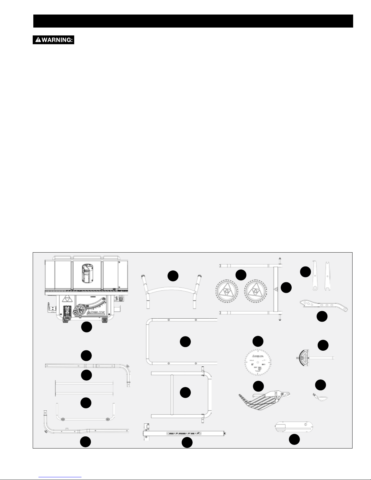
PACKAGE CONTENTS DESCRIPTION (QTY)
have carefully inspected the contents, assembled the
machine and are satisfied that it operates correctly.
Compare package contents to Component Parts List and
Hardware Package List prior to assembly to make sure
all items are present. Carefully inspect parts to make sure
no damage occurred during shipping. If any parts are
missing, damaged or preassembled, do not assemble.
Instead call DELTA® Customer Care at 1-800-223-7278
for assistance.
After assembly remove any protective materials and
coatings from all the parts and the table saw.
A. Saw
B. Stand Handle
C. Wheels
D. Pedal Assembly
E. Right Support Rod
F. Left Support Rod
G. Support Rod Connection Tube
A
H. Cross Connect Assembly
I1. Upper Stand Assembly Part 1
I2. Upper Stand Assembly Part 2
J. T-Square Fence
K. 10 in. Carbide Tipped Blade
L. Miter Gauge
M. Blade Guard Assembly
B
I1
N. Anti-Kickback Pawls
O. Throat Plate
The following items can be found
in their respective storage areas
located on the saw:
a. Blade wrenches (2)
b. Push Stick
C
a
D
K
b
L
E
H
G
F
I2
9
M
J
O
N
Page 10
UNPACKING
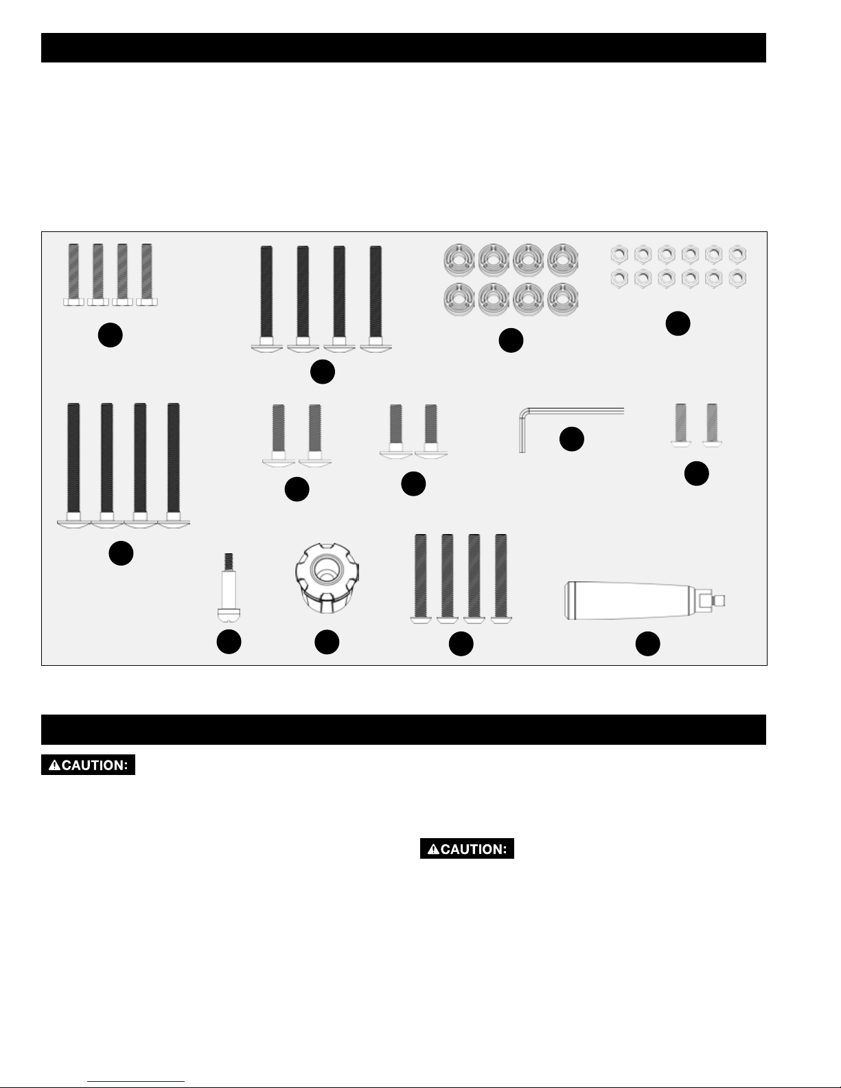
CONTENTS OF HARDWARE BAGS
aa. M6 x 30 Hex Bolt (4)
bb. M8 x 67 Carriage Screw (4)
cc. Plastic Spacer (8)
dd. M8 Locknut (12)
ee. M8 x 75 Carriage Screw (4)
ff. M8 x 35 Carriage Screw (2)
gg. M8 x 30 Carriage Screw (2)
hh. 5mm Allen Wrench (1)
ii. M6 x 20 Button Head Hex Socket Screw (2)
jj. Wheel Handle Shoulder Screw (1)
kk. Height Adjustment Wheel Knob
ll. M8 x 55 Button Head Socket Screw (4)
mm. Fence Handle
aa
bb
ff
ee
jj
To measure fastener length, refer to page 7 of Parts List.
kk
gg
dd
cc
hh
ii
ll
mm
• Do not lift saw without help. Hold it close to your
body while lifting. Keep knees bent and lift with you
legs, not your back.
• Fully assemble saw with stand prior to use.
• Stand assembly is an integral and necessary part of
the support structure for this saw.
• Do not modify saw, or create accessories not
ASSEMBLY
recommended for use with this saw.
• Make sure power switch is in “OFF” position before
connecting to power supply. Do not connect ti power
supply until assembly is complete.
• Avoid contact with blade teeth. Keep blade stored or
lowered when possible.
10 11
Page 11
ASSEMBLY
I1
dd
I2
FIGURE 1
ee
TUBE INSERTS
SHOULDER
ON BOTTOM
TUBE INSERTS
SHOULDER
ON BOTTOM
cc
a
I
ASSEMBLING UPPER STAND
Assemble upper half (I1) of upper stand assembly to lower half (I2) of upper stand assembly as shown in Figure 1 using
M8 x 75mm carriage screw (ee), spacer (cc) and M8 locknut (dd) to each side of upper stand assembly.
NOTE: I1 is attached to saw table assembly and secured with cable ties. Remove cable ties prior to assembling I1 and
I2.
NOTE: Orientation of I2 lock pin is on the right side of the assembly and orientation of I1 will have shoulder of tube
inserts on bottom as shown in Figure 2.
Finished upper stand assembly will appear as shown in Figure 2.
IMPORTANT: Tube insert shoulder on bottom.
LOCK PIN
FIGURE 2
a
11
Page 12
FOOT
PADS
ASSEMBLY
G
F
H
E
FIGURE 3
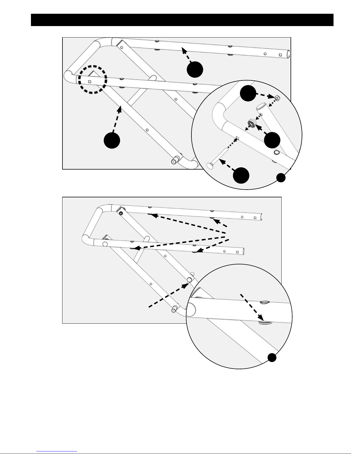
ASSEMBLING THE STAND
Layout the left and right support rod assemblies (E & F).
Place the cross connect assembly (H) between the support rod assemblies and connect the support rod connection tube
(G) to the ends of the support rod assembly tubes as shown in Figure 3.
NOTE: Ensure foot pads are oriented as shown in Figure 3.
dd
I
a
gg
FIGURE 4
Secure the support rod assemblies to the support rod connect tube using two M8 x 30 Carriage bolts (gg) and M8 lock
nuts. (dd)
See Figure 4 & 4a.
12 13
Page 13
aa
ASSEMBLY
a
H
FIGURE 5
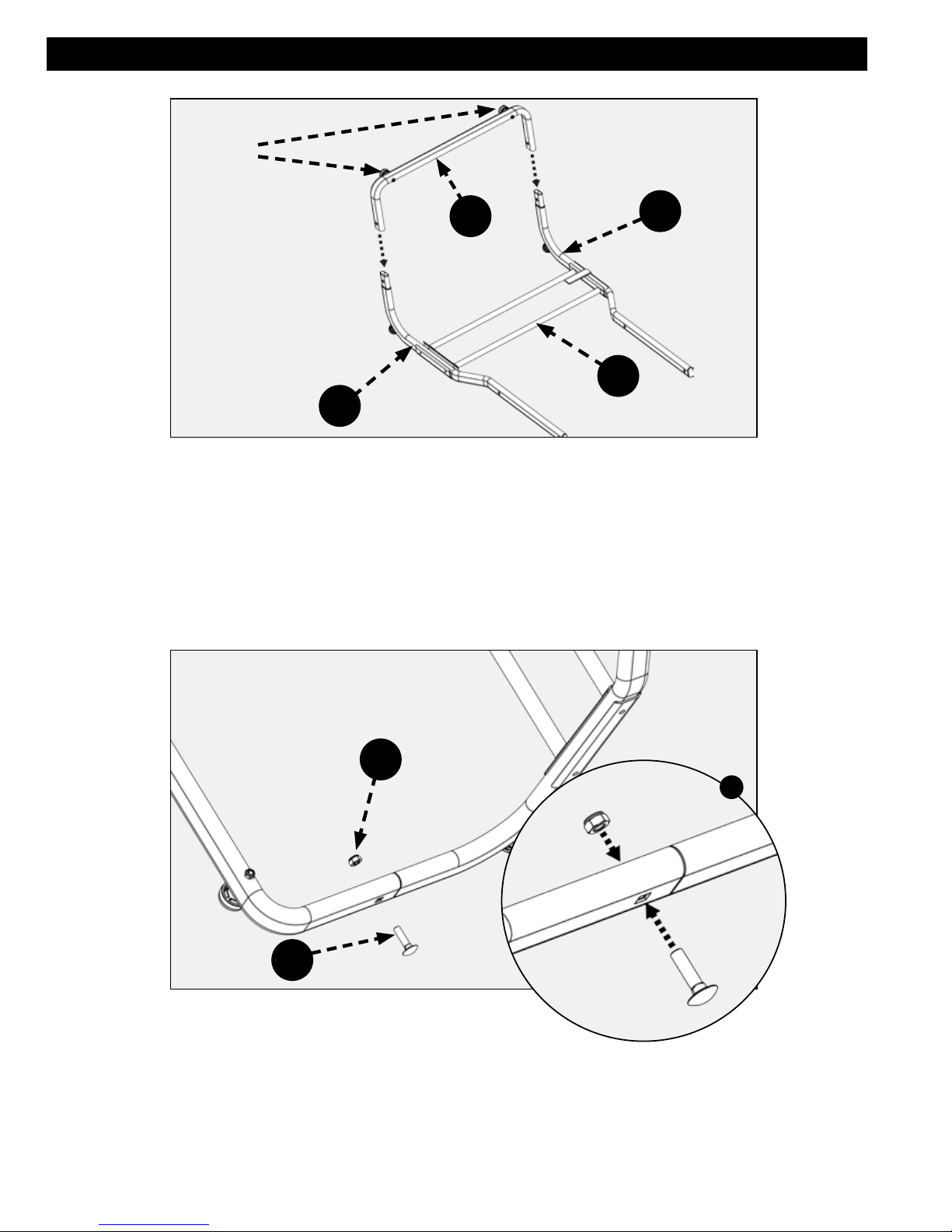
Secure the cross connect assembly (H) to the support rod assembly tubes using four M6 x 30 hex bolts. (aa)
See Figure 5 & 5a.
D
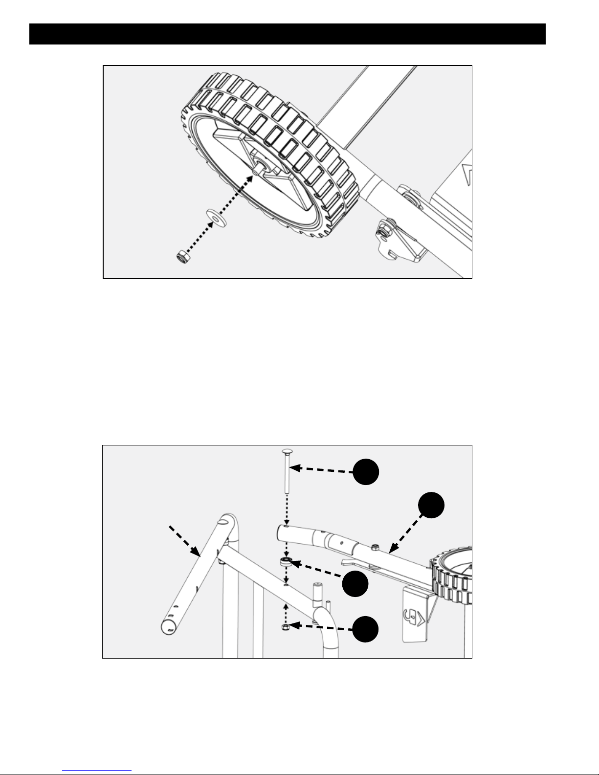
WHEELS
Remove the lock nut and washer from each axle on the pedal assembly (D) as shown in Figure 6.
FIGURE 6
13
Page 14
ASSEMBLY
FIGURE 7
Slide the wheels over axles and secure using the two washers and M8 lock nuts.
See Figure 7.
PEDAL ASSEMBLY
Attach the pedal assembly (D) to the upper stand assembly using two M8 x 75 Carriage screws (ee), spacers (cc)
and M8 lock nuts (dd). See Figures 8 & 9 to verify the correct orientation of the pedal assembly (C) to the upper stand
assembly.
ee
UPPER
STAND
ASSEMBLY
D
cc
dd
FIGURE 8
14 15
Page 15
D
ASSEMBLY
UPPER
STAND
ASSEMBLY
SEE FIGURE
8
FIGURE 9
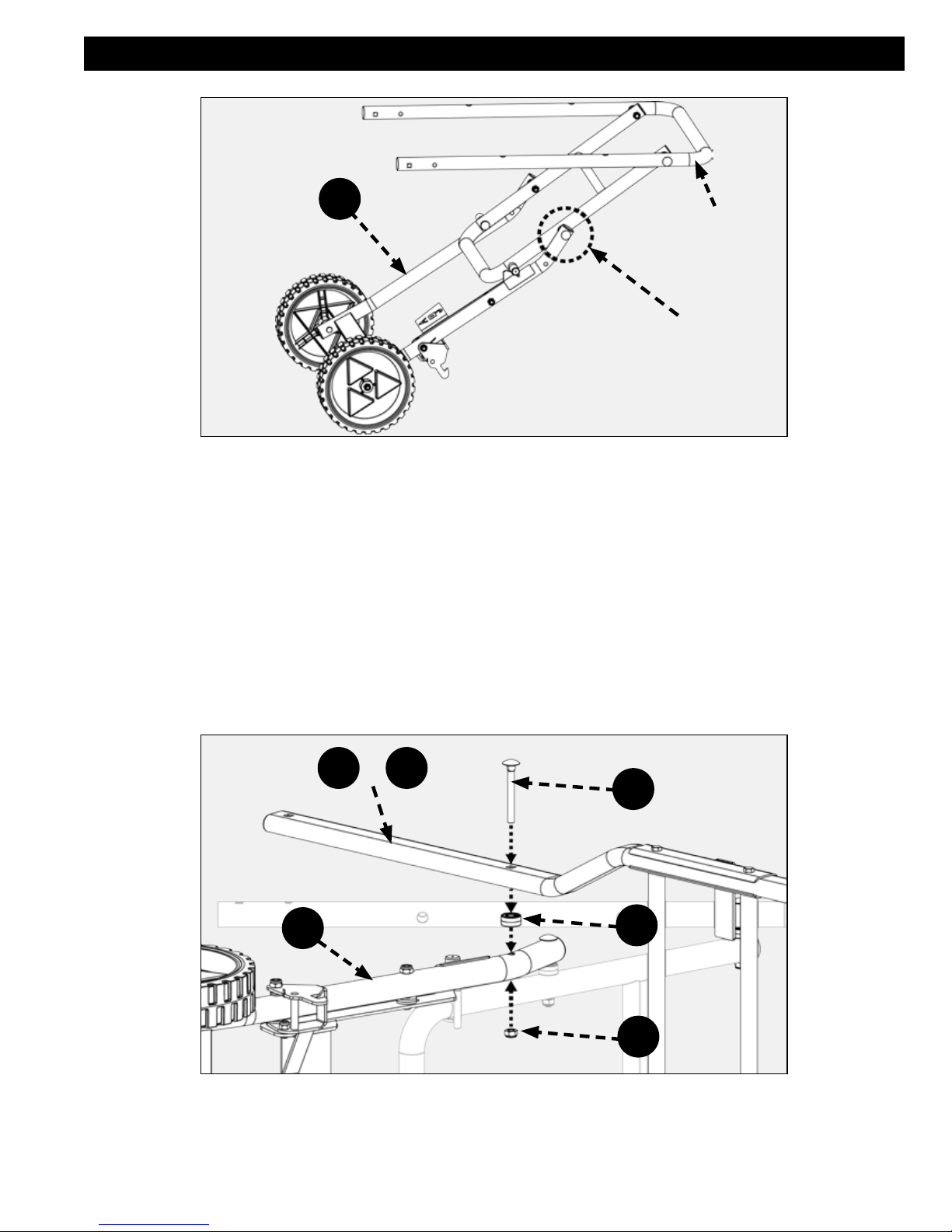
Place the sides of the support rod assembly (E & F) so they are outside of the pedal assembly (D) and the feet are
pointing down. See Figure 11 for correct position of the feet.
Align the hole in the support rod assembly with the hole in the pedal assembly. See Figure 10.
Secure each side of the support rod assembly using two M8 x 67 carriage bolts (bb), spacers (cc) and M8 lock nuts (dd).
See Figures 10 & 11.
NOTE: At any time, to aid in assembly, refer to front cover of this manual for completed saw.
+
E F
bb
D
cc
dd
FIGURE 10
15
Page 16

ASSEMBLY
SEE
FIGURE
10
E
FIGURE 11
FEET
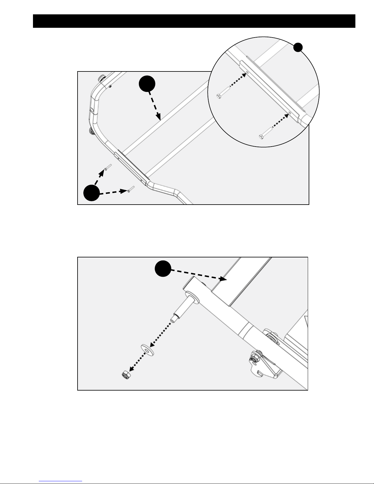
UPPER STAND ASSEMBLY
Insert the stand handle (B) into the upper stand assembly as shown in Figure 12.
Insert M8 x 35 carriage screw (ff) into the square hole at the end of the upper stand assembly (square hole at end of tube
see Figure 12a) secure carriage screw (ff) with M8 Locknut (dd). Repeat this step on the other side of the handle.
B
UPPER
STAND
ASSEMBLY
dd
ff
a
FIGURE 12
16 17
Page 17

ASSEMBLY
+
E F
bb
UPPER
STAND
ASSEMBLY
cc
dd
FIGURE 13
Attach the right and left support rod assemblies (E & F)as shown in Figure 13 to the upper stand assembly with two M8 x
67 carriage screws (bb), spacer (cc) and M8 locknuts (dd) as shown in Figures 13 & 14.
NOTE: Ensure the spacer (cc) is between the support rod assembly and the upper stand assembly as shown in Figure
13.
NOTE: Make sure all hardware is tight but not overtight. The amount of tightening applied to pivoting joints will affect the
stand operation.
SEE
FIGURE
13
+
E F
Correct stand assembly will appear as shown in Figure 14.
FIGURE 14
17
Page 18

1
ASSEMBLY
2
FIGURE 15
ATTACH SAW TO STAND ASSEMBLY
Unlock the bevel lock tilt and rotate the motor assembly enough to remove the shipping foam protecting the saw motor
as shown in Figure 15.
Do NOT turn the handwheel during this step.
SAW
STAND
ASSEMBLY
ll
FIGURE 16
Place saw on stand and align threaded holes in saw with through holes on stand secure with four M8 x 55 button head
socket screws (ll).
See Figure 16.
18 19
Page 19

jj
ASSEMBLY
kk
FIGURE 17
Height Adjustment Knob Installation
1. Insert wheel handle shoulder screw (jj) into height adjustment wheel knob (kk) as shown in Figure. 17.
2. Tighten shoulder screw with Phillips Screw Driver into the Hand Wheel. Height adjustment wheel knob should rotate
freely around shoulder screw when raising or lowering the blade with the Height Adjustment Hand Wheel.
a
UNLOCK
POSITION
CLOSED END
WRENCH
BLADE AND GUARDS
Attach the Blade
After installing height adjustment knob as shown in Figure. 17, raise motor/arbor assembly to the upper
most position to provide easy access to riving knife lock lever and arbor assembly.
Ensure riving knife lock lever is in unlock position. See Figure. 18.
Detach the on-board wrenches located on the right side of the saw by loosening and removing M8 wing
nut.
Place the open-ended wrench (a) on the spindle shoulder between the arbor flange and inner flange.
Place the closed end wrench (a) over the arbor nut. Holding the spindle shaft in place, loosen and remove
the arbor nut and arbor flange.
See Figure 18.
FIGURE 18
19
Page 20

TOOTH
DIRECTION
FRONT OF
SAW
ASSEMBLY
K
ARBOR
SHAFT
FIGURE 19
a
FIGURE 20
Place blade (K) on the arbor shaft with the teeth on the blade pointing toward the front of the saw. Place flanged washer
on the shaft with the large side of the washer against the blade, then secure blade assembly with nut. (Figure. 19)
Tighten nut with blade wrenches (a). Open end wrench will fit on the arbor shaft between the inner flange washer and the
motor assembly (if neccessary, turn arbor shaft to align flats on the arbor shaft to the wrench). Closed end wrench will fit
on the nut. See Figure 20.
Return wrenches (a) to onboard storage location. Position the riving knife in the “Thru-cut” position prior to installation of
thoat plate.
Details for positioning the riving knife are on page 32 RIVING KNIFE POSITION AND ALIGNMENT Section.
See Figure 21.
20 21
Page 21

ASSEMBLY
THRU CUT
POSITION
FIGURE 21
RIVING
KNIFE
LOCK
POSITION
WEAR
O
FIGURE 22
To reduce the risk of serious injury,
• the riving knife must be installed for every through cut and for every non-through cut unless the riving knife would
interfere with the cut.
• always use a blade with the correct thickness to match the riving knife. (0.10” (2.6mm) min. kerf width and 0.073”
(1.85mm) max body thickness)
• The riving knife must be securely positioned in the “up” or “through cut” position when using the antikickback pawls
and blade guard.
• Make sure the riving knife is properly aligned to the blade. (See Riving Knife Position and Alignment, Page 33.
PLATE
Insert Throat Plate
Refer to Figure 22.
Place the throat plate (O) in place with the wear plate on the rear.
Engage the rear tab on the throat plate under the table and press the front end down until the front tab snaps into place
on the table.
21
Page 22

ASSEMBLY
FIGURE 23
a
SCREW UNDER
THROAT PLATE
FIGURE 24
Level the throat plate to the table top using (4) flat head screws. See Figure 23 and 24. For more details about leveling
throat plate, see page 29.
NOTE: There is a fifth flat head screw under the throat plate that is adjusted to provide support under the wear plate.
Adjust this screw as needed to provide support.
To reduce risk of serious injury, do not attempt to secure the throat plate to the table using the throat
plate leveling screws.
22 23
Page 23

ASSEMBLY
PRESS
PIN
M
N
RIVING
KNIFE
FIGURE 25
LOCK
TAB
SUPPORT
ARMS
Anti-Kickback Pawls and Blade Guard
Press spring loaded pin on the right side of the anti-kickback pawl assembly (N) insert over the middle slot on the riving
knife.
Once inserted, release the spring-loaded pin so that it pops back into place. Ensure it is locked in place by gently pulling
up on the anti-kickback pawl assembly (N).
Hold the blade guard assembly (M) as shown in Figure 26 and engage the pin with the slot in the riving knife. Pull blade
guard assembly up into place.
Rotate the blade guard so that the support arms are parallel to the table. Then lock the blade guard in place by
depressing the lock tab.
Verify the Blade Guard Assembly is properly locked in place. Do this by gently lifting up on the support arms after the
lock tab has been depressed. If blade guard is not properly locked onto the riving knife, support arms will raise up and
lock tab will spring up to the unlocked position.
See Figure 27.
To reduce risk of serious injury. It is important that you do not use the table saw if blade guard assembly
is not locked into place on the riving knife.
FIGURE 26
FIGURE 27
23
Page 24

ASSEMBLY
FIGURE 28
ii
Outfeed Support Stops
Refer to Figure 28.
Extend the rear table support to expose the two holes. Insert an M6 x 20 button head hex socket screw (ii) from
underneath, tighten with the supplied allen wrench.
Repeat on other side of outfeed suport.
J
mm
Assemble handle (mm) to fence assembly (J) as shown in Figure 29.
FIGURE 29
24 25
Page 25

J
LOCKED
POSITION
ASSEMBLY
FIGURE 30
Position the T-square fence (J) over the front and rear rails. Ensure the fence lock is in the unlocked (up) position.
Lower T-square fence (J) on to both front and rear rails. Position T-square fence (J) on the table as desired and lock into
place.
See Figure 30.
25
Page 26

ASSEMBLY
a
b
CORD
WRAP
N
M
FIGURE 31
L
J
FIGURE 32
NOTE: Prior to placing the rip fence in the storage position you must temporally remove the miter gauge from the
storage position.
ON-BOARD STORAGE
Storage is located on the left panel, right panel and back side of the tool as shown in Figures 31 & 32.
b. Push Stick
N. Anti-kickback assembly
a. Wrenches
M. Blade guard assembly
J. Fence
L. Miter gauge
Electrical Cord wrap
26 27
Page 27

OPERATION
Failure to follow these rules may result in serious personal injury.
READ ENTIRE MANUAL. In addition to reading these operating instructions, it is important to read and understand
the entire manual before operating this saw. Follow all applicable instructions regarding assembly, preparation, and
adjustment prior to making any cuts and comply with all safety rules and warnings in this section and elsewhere
throughout this manual.
1. Each time you use the saw, run through the
following checklist:
• Are the power source and power connections
adequate for the saw?
• Are the saw and work area free of clutter and
by-standers?
• Is the blade tight and properly aligned?
• Does the riving knife thickness match the blade?
• Are the blade and riving knife properly aligned?
• Is the operator qualified to make the cut and familiar
with all of the relevant safety rules, warnings and
instructions included in this manual?
• Is the operator and everyone in proximity to the saw
wearing appropriate eye, hearing and respiratory
equipment?
• Are the bevel angle and height adjustment knobs
locked in the proper position?
• Is the blade set at the proper height?
• If ripping, is the rip fence parallel to the blade and
securely locked in place?
• If crosscutting, is the miter gauge knob too tight?
• If making through cuts with a standard blade, are
the blade guard riving knife and anti-kickback pawls
properly attached and properly functioning with both
guards contacting the table surface?
• Is there proper clearance and support for the
workpiece as it leaves the blade?
• Are any cutting aids needed? If so, are they in place,
or within reach for proper use?
2. The use of attachments and accessories not
recommended by DELTA® Power Equipment
Corporation may result in injury.
3. Replace or sharpen the anti-kickback fingers
when the points become dull.
4. Make sure saw is stable and cutting can be
accomplished without tipping the saw.
5. Never use the fence and miter gauge together
without using a cutoff block as previously
described.
6. The proper throat plate must be in place at all
times.
7. If your saw makes an unfamiliar noise or if it
vibrates excessively, cease operating immediately
until the source has been located and the
problem corrected.
8. Never perform freehand cutting, plunge cutting,
re-sawing or cove-cutting.
AVOID KICKBACK
A kickback can occur when the workpiece pinches the
blade, or binds between the saw blade and the rip fence
or other fixed object. This can cause the workpiece
to rise from the table and/or be thrown back toward
the operator. See instructions for reducing the risk of
kickback in page 7 of this manual.
IF KICKBACK OCCURS, turn the saw “OFF” and verify
proper alignment of the blade, riving knife and miter
gauge or rip fence, and the proper functioning of the
riving knife, anti-kickback assembly and blade guard
before resuming work.
27
Page 28

OPERATION
LOCK
OUT
FIGURE 33
TURNING THE SAW ON AND OFF
ON
OFF
The ON/OFF paddle switch is located on the left side of the front panel of the saw.
To turn the saw ON lift the switch. Press the switch down to turn the saw OFF.
When not in use, the saw should be turned off and the power switch locked out to prevent unauthorized use. To lock out
power switch, use a standard long shackle lock, with a shackle posts no larger than 9/32-inch (7mm) thick.
See Figure 33.
FIGURE 34 FIGURE 35
TRANSPORTING THE SAW
To fold stand for moving, return side and rear extension tables to inner position lock side extension into place. Stow rip
fence and miter gauge. Grasping handle bar, push the stand release pedal with foot and tilt up and forward until the saw
rests on the wheels and stand feet.
See Figures 34 & 35.
28 29
Page 29

MAKING CUTS
Failure to comply with the following
warnings may result in serious
personal injury.
• Never touch the free end of the workpiece or a free
piece that is cut off, while the power is on and/or the
saw blade is rotating. Blade contact or binding may
occur, resulting in a thrown workpiece.
• When sawing a long workpiece or a panel, use a
work support, such as a sawhorse, rollers or outfeed
table at the same height as the table surface of the
saw.
• Never try to pull the workpiece back or lift it off the
table, turn the switch off, allow the blade to stop,
raise the anti-kickback teeth on each side of the
riving knife if necessary, and slide the workpiece out.
• Before connecting the table saw to the power source
or operating the saw, always inspect the blade guard
assembly and riving knife for proper alignment and
clearance with the saw blade. Check alignment after
each change of beveling angle.
• A rip fence should ALWAYS be used for ripping
operations to prevent loss of control and personal
injury. Always lock the fence to the rail. NEVER
perform a ripping operation freehand.
• When making bevel cuts, place the fence on the right
side of the blade so that the blade is tilted away from
the fence and hands. Keep hands clear of the blade
and use a push stick to feed the workpiece unless
the workpiece is large enough to allow you to hold it
more than 6 inches (152 mm) from the table.
• Before leaving the saw unattended, lock out power
switch, or take other appropriate measures to
prevent unauthorized use of the saw.
Cross Cut
Beveled Cross Cut Beveled Rip Cut
Mitered CrosscutRip Cut
Compound Miter Cut
29
Page 30

RIP CUTS
MAKING CUTS
1. Remove miter gauge.
2. Make sure bevel angle is set to 0º.
3. Set blade to correct height for workpiece.
4. Install rip fence and lock it down parallel with and at
desired distance from blade.
5. Keep fingers at least 6 inches from the blade at
all times. When the hand cannot be safely out
between the blade and the rip fence, select a larger
workpiece, or use a push stick and other cutting
aids, as needed, to control the workpiece.
6. Make sure the workpiece is clear of the blade (at
least 1 inch or 25 mm away) before starting the saw.
7. Turn saw on.
8. Hold the workpiece flat on the table and against the
fence (A). The workpiece must have a straight edge
against the fence and must not be warped, twisted
or bowed. See proper hand position in Figure 36.
9. Let blade build up to full speed before moving
workpiece into the blade.
10. Both hands can be used while starting the cut as
long as hands remain 6 inches from the blade.
11. Keep the workpiece against the table and fence
and slowly feed the workpiece rearward all the way
through the saw blade. Do not overload the motor by
forcing the workpiece into the blade.
12. Use the push stick and any other cutting aids, as
needed, to hold the workpiece against the table and
fence, and push the workpiece past the blade. A
push stick is included with this saw, and instructions
are included to make additional push sticks and
other cutting aids.
13. Do not push or hold onto the free or cut-off side of
the workpiece.
14. Continue pushing the workpiece until it is clear of
the blade. Do not overload the motor by forcing the
workpiece into the blade.
15. When cut is complete, turn saw off. Wait for blade to
come to a complete stop before removing workpiece
from table.
A
BEVEL RIPPING
Bevel ripping is the same as ripping except the bevel
angle (A) is set to an angle other than 0. When making
a bevel rip cut, place the fence on the right side of the
blade so that the blade is tilted away from the fence and
hands.
See Figure 37.
FIGURE 36
A
FIGURE 37
30 31
Page 31

MAKING CUTS (CONTINUED)
CROSSCUTTING
• NEVER use the fence as a guide or length stop
when crosscutting, unless you are using the fence as
described on page 28 Figure 46 of this manual.
• The cut-off piece must never be confined in any
through-sawing (cutting completely through the
workpiece) operation—to prevent pinching blade
which may result in a thrown workpiece and possibly
injury.
• When using a block as a cut-off gauge, the block
must be at least 3/4-inch (19mm) thick. It is very
important that the rear end of the block be secured in
a position where the workpiece is clear of the block
before it enters the blade to prevent binding of the
workpiece.
You can use the miter gauge in either table slot on nonbevel cuts. To increase surface area of miter gauge face,
add an auxiliary face (See Cutting Aids section on page
27 of this manual.)
To make a crosscut, refer to Figure 38 and follow this
process:
1. Remove rip fence.
2. Make sure bevel angle is set to 0°.
3. Set blade to correct height for workpiece.
4. Place miter gauge in either miter slot.
5. Set miter gauge to 90° and tighten miter gauge lock
knob
6. Hands must remain at least 6 inches from blade
throughout entire cut. If workpiece is too small to
keep hands at least 6 inches away from the blade,
select a larger workpiece, or attach an auxiliary face
to the miter gauge and attach workpiece to auxiliary
face, For instructions about making auxiliary faces,
see Cutting Aids section on page 27 of this manual.
7. Make sure the workpiece is clear of the blade - at
least 1 inch or 25mm away - before starting the saw.
8. Turn saw on.
9. Let blade build up to full speed before moving
workpiece into the blade.
10. Hand closest to blade should be placed on miter
gauge lock knob and hand farthest from blade
should hold workpiece firmly against the miter gauge
face. Do not push or hold onto the free or cut-off side
of the workpiece.
11. Slowly feed the workpiece rearward all the way
through the saw blade. Do not overload the motor by
forcing the workpiece into the blade.
12. When cut is complete, turn saw off. Wait for blade
to come to a complete stop before removing cut off
piece from table.
FIGURE 38
BEVEL CROSSCUTTING
Bevel crosscutting is the same as crosscutting except
the bevel angle (A) is set to an angle other than 0°. When
making a bevel crosscut, place the miter gauge in the
right miter slot so that the blade is tilted away from the
gauge and hands. See Figure 39.
MITER CUTS
Miter cuts are cross cuts with the miter gauge set at an
angle other than 90°. Miter gauge can be adjusted to one
of the 8 positive stop angles or as desired to an individual
angle increment.
• Miter angles more than 45˚ may force the blade
guard assembly into the saw blade causing damage
to the blade guard assembly and personal injury.
Before starting the motor, test the operation by
feeding the workpiece into the blade guard assembly.
If the blade guard assembly contacts the blade,
place the workpiece under the blade guard assembly
but not touching the blade - before starting the
motor.
A
FIGURE 39
• Certain workpiece shapes, such as molding may
not lift the blade guard assembly properly. With
the power off, feed the workpiece slowly into the
blade guard area and until the workpiece touches
the blade. If the blade guard assembly contacts the
blade, place the workpiece under the blade guard
assembly - but not touching the blade - before
starting the motor.
31
Page 32

MAKING CUTS (CONTINUED)
COMPOUND MITER CUTS
This is a combination of bevel crosscutting and mitering.
Refer to Figure 40 and follow the instructions for both
bevel crosscutting and mitering. Remember to use the
right miter slot on the right side of the blade for all bevel
cuts.
5
LARGE PANEL CUTS
Place workpiece supports at the same height as the
saw table behind saw to support the cut workpiece, and
alongside (s) of saw, as needed. Depending on shape of
panel, use rip fence or miter gauge to control workpiece.
If a workpiece is too large to use either a rip fence or a
miter gauge, it is too large for this saw.
NON-THROUGH CUTS
The use of a non-through cut is essential to cutting
grooves, and rabbets. Non-through cuts can be made
using a standard blade having a diameter of 10 inches.
Non-through cuts are the only type of cuts that should
be made without the blade guard assembly installed.
Make sure the blade guard assembly is reinstalled upon
completion of this type of cut.
• When making non-through cuts, follow all applicable
warnings and instructions listed below in addition to
those listed above for the relevant through cut.
• When making a non-through cut, blade is covered by
workpiece during most of cut. Be alert to exposed
blade at start and finish of every cut.
9
FIGURE 40
• Never feed wood with hands when making any nonthrough cuts such as rabbets or grooves. Always
use miter gauge, push blocks or push sticks, and
featherboards where appropriate.
• In addition to this section, read the appropriate
section which describes the type of through or cut.
For example, if your non-through cut is a straight
cross cut, read and understand the section on
straight cross cuts before proceeding.
• Once all non-through cuts are completed, unplug
saw and return riving knife to through cut position.
Install anti-kickback pawls and blade guard.
• Carefully follow the instructions accompanying any
specialized blades for proper installation, set up and
operation.
MAKING A NON-THROUGH CUT
1. Unplug saw.
2. Unlock bevel lock.
3. Adjust bevel angle to 0°.
4. Lock bevel lock.
5. Remove blade guard and anti-kickback pawls.
6. Place riving knife in “lowered” position. See RIVING
KNIFE POSITION AND ALIGNMENT Section on page
32.
7. Set blade to correct depth for workpiece.
8. Depending on shape and size of wood, use either rip
fence or miter gauge.
9. Plug saw into power source and turn saw on.
10. Let blade build up to full speed before moving
workpiece into blade.
11. Always use push blocks, push sticks, and/or
featherboards when making non-through cuts to
reduce the risk of serious injury.
12. When cut is made, turn saw off. Wait for blade to
come to a complete stop before removing workpiece.
32 33
Page 33

MAKING CUTS
MAKING A DADO CUT
Dado blades are stacked blades that can be used when
making non-through cuts including through cut slots.
Dado blades require a special throat plate. Dado blades
and throat plates are all sold separately.
• Carefully follow the instructions accompanying
the dado blade for proper installation, set up
and operation. Additional guides can be found
in woodworking and carpentry websites and
publications.
• Do not attempt to stack dado blades thicker than
13/16 inch (20.64 mm). Do not use dado blades
larger than 8-inches (200 mm) in diameter.
• The riving knife and blade guard assemblies cannot
be used when dadoing. They must be removed
as described in Riving Knife and Blade Guard
Operations section. Use EXTREME care when using
the dado without the blade guard assembly and
riving knife.
• Use push sticks, hold-downs, jigs, fixtures or feather
boards to help guide and control the workpiece when
the guard cannot be used.
• Be sure to reinstall the riving knife, anti-kickback
pawls blade guard and standard throat plate,
and check adjustments when the dado cuts are
complete.
• The accessory dado head set throat plate, shown in
FIGURE 41
Figure 41, must be used in place of the standard
throat plate. Be sure the throat plate is level to the
table before you proceed.
• Always check the dado blade clearance with other
components before plugging in the saw.
• Never attempt to use the dado head in a bevel
position.
NOTE: The standard outer arbor flange cannot be used
with certain dado blade combinations. In those cases,
tighten the arbor nut directly against the dado blade set.
Save the outer arbor flange for use with other blades and
dado combinations.
CUTTING AIDS AND ACCESSORIES
PUSH STICK
In order to operate your table saw safely, you must use a
push stick whenever the size or shape of the workpiece
would otherwise cause your hands to be within 6-inches
(152mm) of the saw blade or other cutter. A push stick is
included with this saw.
No special wood is needed to make additional
pushsticks as long as it is sturdy and long enough with
no knots, checks or cracks. A length of approximately 16
inches (400mm) is recommended with a notch that fits
against the edge of the workpiece to prevent slipping.
It’s a good idea to have several push sticks of the same
minimum length, 16 inches (400mm), with different size
notches for different workpiece thicknesses.
The shape can vary to suit your own needs as long as
it performs its intended function of keeping your hands
away from the blade. Angling the notch so the push stick
can be held at a 20 to 30-degree angle from the saw’s
table will help you to hold down the workplace while also
moving the saw.
FIGURE 42
To construct a push stick, refer to the layout shown in
Figure 42.
33
Page 34

CUTTING AIDS AND ACCESSORIES (CONTINUED)
AUXILIARY MITER GAUGE
FACING
An auxiliary miter gauge facing is used to increase the
surface area of the miter gauge face.
If desired, you can fit the miter gauge with an auxiliary
wood facing that should be at least 1-inch (25mm) higher
than the maximum depth of cut, and at least as wide as
the miter gauge.
This auxiliary wood facing can be fastened to the front
of the miter gauge by using (2) M6 or 1/4-20 flat head
screws and nuts, placing the nuts into the slots provided
in the face of the miter gauge body.
See Figure 43.
Make sure the screws are long enough to secure the
facing.
Flat head must be recessed into face of
board.
PUSH BLOCK
1. Select a piece of wood about 4-inches wide,
6-inches long and 1- to 2-inches thick (a cutoff from
a 2 by 4 makes a good blank for a push block).
2. Drill a hole in the block and glue in a dowel to use as
a handle (you can angle the hole to provide a more
comfortable grip on the handle).
3. Glue a piece of rough or soft material such as
sandpaper or rubber to the bottom of the block to
grip the workpiece (old mouse pads work well).
See Figure 44.
FIGURE 43
FIGURE 44
34 35
Page 35

CUTTING AIDS AND ACCESSORIES (CONTINUED)
FEATHERBOARD
Featherboards are used to keep the workpiece in contact
with the fence and table (Figure 45), and help prevent
kickback. Featherboards are especially useful when
ripping small workpieces and for completing non-through
cuts. The end is angled with a series of narrow slots to
give a friction hold on the workpiece, It is locked in place
on the table or fence with a c-clamp.
To avoid binding between the
workpiece and the blade, make sure
a horizontal feather board presses only on the uncut
portion of the workpiece in front of the blade.
Dimensions for making a typical featherboard are shown
in Figure 45 . Make your featherboard from a straight
piece of wood that is free of knots and cracks. Clamp
featherboards to the fence and/or table so that the
featherboard will hold the workpiece against the fence or
table.
1. Select a solid piece of lumber approximately 3/4-inch
thick, 2 1/2-inches wide and 12-inches long.
2. Mark the center width on one end of stock. Miter
width to 70° (see miter cut section for information on
miter cuts).
3. Set rip fence to allow approximately a 1/4-inch
“finger” to be cut in the stock.
4. Feed stock only to mark previously made at 6 inches.
5. Turn saw off and allow blade to completely stop
rotating before removing stock.
6. Reset rip fence and cut spaced rips into workpiece
to allow approximately 1/4-inch fingers and 1/8-inch
spaces between fingers.
FIGURE 45
CUT OFF GAUGE
When crosscutting a number of pieces to the same
length, you can clamp a block of wood (A) (See Figure 46)
to the fence and use it as a cut-off gauge. The block (A)
must be at least 3/4-inch (19 mm) thick to prevent the cut
off piece from binding between the blade and the fence.
Once the cut-off length is determined, lock the fence and
use the miter gauge to feed the workpiece into the blade.
Always position the entire cut-off
gauge in front of the saw blade.
JIGS
Jigs may be created with a variety of special set-ups
to control particular workpiece shapes for particular
cuts. Guidance on how to make specialized jigs can
be found in woodworking and carpentry websites and
publications.
A
FIGURE 46
Do not attempt to create or use a jig
unless you are thoroughly familiar with
table saw safety. Do not use any jig that could result
in pinching a kerf or jamming the workpiece between
the jig and the blade. Incorrect setups may cause
kickback which could result in serious injury.
35
Page 36

MAKING ADJUSTMENTS
SCREW UNDER
THROAT PLATE
a
FIGURE 47
LEVELING THE THROAT PLATE
The front, rear and sides of the throat plate must be level with the surface of the table.
There are four screws pre-assembled to the table that are used to level the throat plate.
If the throat plate is not flush with the surface of the table, adjust these screws to ensure the entire throat plate is flush
with the table. They can be accessed and adjusted without removing the throat plate. Do not attempt to mount the throat
plate down using the throat plate leveling screws.
See Figures 47 & 47a.
FIGURE 48
SQUARING THE BLADE VERTICALLY TO THE TABLE
Place a framing square (B) on the table surface and against both blade and riving knife. The framing square should be in
full contact with the blade face and riving knife.
See Figure 48.
If it is not square, adjust the 0-degree stop as shown in “Adjusting The Bevel Stops” below.
See Figures 49, 49a, 50 and 50a.
36 37
Page 37

MAKING ADJUSTMENTS
45°
UNLOCK
LOCK
FIGURE.
a
ADJUSTING THE BEVEL STOPS
If the blade is not vertically square with the table, you must adjust the 0-degree positive stop located on the inside of
the bevel track at the left end of the bevel track opening as shown in Figures 50 and 50a.
Unlock the bevel/height adjustment locking lever and position the adjustment wheel to the right in order to gain easy
access to the 0-degree positive stop. Then lock the adjustment lever.
Turn the 0-degree positive stop set screw to right or left to adjust stop location.
Unlock the adjustment wheel, return the blade to the 0-degree position, making sure it makes contact with the
positive stop, and re-lock the adjustment wheel in place.
Recheck the position of the blade to the table surface using a framing square (See “SQUARING THE BLADE
VERTICALLY TO THE TABLE” ON THIS PAGE).
Continue repeating previous two steps until the blade is vertically square to the table.
You can use this same procedure in order to check the 45-degree positive stop, located at the far right end of the
bevel track, just inside the bevel track opening as shown in Figures 49 & 49a.
UNLOCK
LOCK
FIGURE 49
FIGURE.
FIGURE 50
37
a
0°
Page 38

MAKING ADJUSTMENTS
ADJUSTMENT
WHEEL
LOCKING
LEVER
UNLOCK
LOCK
FIGURE 51
ADJUSTING THE BLADE HEIGHT
For all through cuts, the top of the blade points should be above the workpiece and the bottom of the blade gullets are
below the top surface of workpiece.
For non-through cuts, the top of the blade points should be set to the depth of the cut.
To adjust the height of the blade, refer to Figure 51 and do the following:
Make sure the bevel/height adjustment locking lever is in the locked position.
Adjust the blade height by turning the bevel/height adjustment wheel. Clockwise will raise the blade and
counterclockwise lowers it.
CHANGING THE BEVEL
Unlock the bevel/height adjustment locking lever by pulling it into the unlock position.
Holding knob/wheel, slide the bevel indicator to the desired angle.
When the blade is at desired angle, lock the bevel/height adjustment locking lever by pushing it down to the lock
position.
See Figure 51.
38 39
Page 39

MAKING ADJUSTMENTS
LOCK
KNOB
USING THE MITER GAUGE
FIGURE 52
There are two miter gauge grooves. one on either side of the blade. When making a 90º cross cut, use either groove. For
beveled cross cut use the groove on right so that the blade is tilted away from miter gauge and hands.
Loosen the miter gauge lock knob. Rotate the gauge until desired angle on scale is reached. Retighten lock knob.
See Figure 52.
USING THE REAR OUTFEED SUPPORT
The out-feed support slides out to provide additional support for cutting long work pieces.
Ensure the power switch is in the OFF position. From the rear of the saw, grasp the out-feed support with both hands
until it is fully extended.
See Figure 53.
FIGURE 53
39
Page 40

POINTER
MAKING ADJUSTMENTS
UNLOCK
EXTENSION
TABLE
LOCK
B
FIGURE 54
USING THE RIGHT HAND TABLE EXTENSION
The table extension, located on the right side of the table, enables you to increase the width of the saw table to
accommodate oversized workpieces.
To use the table extension, refer to Figure 54 and do the following:
Release the table extension lock (B) by moving it up. Slide side table extension out to the right. Use the blue pointer on
the top scale to determine desired distance. When extension table is set to desired width, push lock lever to the lock
position.
SET SCREW
HEX
WRENCH
FIGURE 55
RIP FENCE ADJUSTMENTS
To adjust rip fence so it is parallel to the blade, make adjustments to the set screws on the front of the fence as shown in
Figure 55.
40 41
Page 41

MAKING ADJUSTMENTS
FIGURE 56
To adjust the rip fence so it is perpendicular to the table, make adjustments to the nylons screws on the top of the rip
fence “T” as shown in Figure 56.
a
To make adjustments to clamping pressure for rip fence, adjust screw on back of fence to the right to tighten and to the
left to loosen clamping pressure.
See Figures 57 & 57a.
FIGURE 57
41
Page 42

RIVING KNIFE POSITION AND ALIGNMENT
UNLOCK
LOCK
FIGURE 58
LOWERING THE RIVING KNIFE
Remove throat plate.
1. With the blade assembly to the highest possible position, carefully reach alongside the blade and raise the riving
knife locking lever up to unlock the riving knife.
2. Gently move the riving knife to the right to release it from the lock pins in the riving knife assembly.
3. Slide the riving knife down and backward until you feel the lock pins engage the riving knife in the “Non-Thru
Cut” position. When properly aligned in this position, the “Non-Thru Cut” line on the riving knife will be parallel to
and level with the table. See Figure 59 on page 33.
4. Return the riving knife lock lever to the lock position.
5. Make sure the riving knife is securely installed and properly aligned with the blade.
To raise riving knife to “Thru-Cut” position repeat steps 1-5 and on step 3 raise riving knife up and forward.
Reinstall throat plate.
42 43
Page 43

RIVING KNIFE POSITION AND ALIGNMENT
NON-THRU
CUT
THRU-CUT
BB2
BB3
AA
AA
BB1
Location point for NON-THRU CUT POSITION
NOTE: Riving knife is located in this position for “NON-THRU” cuts and is also in this position when packaged for
shipment.
Location point for THRU CUT POSITION as shown in Figure 59. (Operator should adjust the riving knife to this position
when making “THRU” cuts.)
(NOTE: You must locate the riving in THRU CUT position prior to making any alignment adjustments to the riving knife
alignment to the blade.)
FIGURE 59
RIVING KNIFE ALIGNMENT
Parallel Alignment
The plane of the riving knife is parallel to the plane of the blade but the riving knife and the blade are not in line with
each other.
If a parallel adjustment is required use Figure 59 and Figure 60 to make the following adjustments:
1. Loosen the two hex socket head screws (AA)
2. Tighten or loosen the adjustment screw (BB1) to adjust the datum line of the riving knife to be aligned with the
blade.
3. Adjust set screw (BB2) and (BB3), to assist with the alignment of the riving knife to be parallel to the blade.
4. Tighten hex socket head screws (AA).
FIGURE 60
43
Page 44

RIVING KNIFE POSITION AND ALIGNMENT
FIGURE 61
Horizontal Alignment
The plane of the riving knife appears to be twisted in comparison to the plane of the blade. (Can be seen looking straight
down on the blade and riving knife.)
If the riving knife has horizontal misalignment, adjust as follows using Figure 59 and Figure 61.
1. Loosen the two hex socket head screws (AA)
2. Adjust screw (BB2) to align the riving knife to the blade, if still out of alignment then adjust (BB3) until proper
alignment is achieved. Do not adjust (BB1).
3. Tighten screws (AA).
a
FIGURE 62
Vertical Alignment
The plane of the riving knife appears to be twisted in comparison to the plane of the blade from the bottom of the riving
knife to top of the riving knife. (Can be seen looking from the front of the saw.)
If the riving knife has vertical misalignment, adjust as follows using Figure 59 and Figure 62.
1. Loosen the two hex socket head screws (AA)
2. Make adjustments to (BB2) and (BB3), to align riving knife to the blade. No adjustment is needed for (BB1).
3. Tighten screws (AA).
44 45
Page 45

MAINTENANCE
To reduce the risk of injury, turn unit off and disconnect it from power source before cleaning or
servicing, before installing and removing accessories, before adjusting and when making repairs. An
accidental start-up can cause injury.
KEEP MACHINE CLEAN
Periodically blow out all air passages with dry compressed air. All plastic parts should be cleaned with a soft damp cloth.
NEVER use solvents to clean plastic parts. They could possibly dissolve or otherwise damage the material.
Wear certified safety equipment for eye, hearing and respiratory protection while using compressed air.
MAINTENANCE REMINDERS
Wear certified safety equipment for eye, hearing and respiratory protection while using compressed air.
Specific areas which require regular maintenance include:
RIVING KNIFE CLAMP PLATE: Keep this area free of dust and debris buildup. Blow out area regularly with compressed
air.
NOTE: If the riving knife clamp can’t move freely, have the saw serviced by authorized D ELTA® Power Equipment
Corporation service center personnel.
WORM GEARS: Keep the bevel gears free of dust and debris buildup. Blow out area regularly with compressed air. Use
a lithium-based multipurpose grease as needed on these gears.
CLEAN SAWDUST BUILDUP OUT OF CABINET PERIODICALLY: NOTE: Debris can also be removed from the saw
from below the throat plate, inside the dust port.
TROUBLESHOOTING
For assistance with your machine, visit our website at www.DeltaMachinery.com for a list of service centers or call
DELTA® Power Equipment Corporation Customer Care at 1-800-223-7278.
FAILURE TO START
If your machine fails to start, check to make sure the prongs on the cord plug are making good contact in the receptacle,
and check reset button on power switch housing. Also, check for blown fuses or open circuit breakers in your power
line.
ACCESSORIES
A complete line of accessories is available from your DELTA® Supplier, DELTA® Factory Service Centers and Delta®
Authorized Service Centers. Please visit our web site at www.DeltaMachinery.com for an online catalog or for the name
or your nearest supplier.
Since accessories other than those offered by DELTA® have not been tested with this product, use of
such accessories could be hazardous. For safest operation, only DELTA® recommended accessories
should be used with this product.
45
Page 46

WARRANTY
To register your tool for warranty service visit our website at www.DeltaMachinery.com.
Five Year Limited New Product Warranty
DELTA® will repair or replace, at its expense and at its option, any new DELTA® machine, machine part, or machine accessory which in
normal use has proven to be defective in workmanship or material, provided that the customer returns the product prepaid to a DELTA
factory service center or authorized service station with proof of purchase of the product within ve years and provides DELTA
reasonable opportunity to verify the alleged defect by inspection. For all refurbished DELTA
®
DELTA
will not be responsible for any asserted defect which has resulted from normal wear, misuse, abuse or repair or alteration made
or specically authorized by anyone other than an authorized DELTA
®
DELTA
be liable for incidental or consequential damages resulting from defective products. Some states do not allow the exclusion or
limitation of incidental or consequential damages, so the above limitation or exclusion may not apply to you. This warranty is DELTA
sole warranty and sets forth the customer’s exclusive remedy, with respect to defective products; all other warranties, express or im-
plied, whether of merchantability, tness for purpose, or otherwise, are expressly disclaimed by DELTA
coverage and warranty repair information, visit www.DeltaMachinery.com or call 1-800-223-7278. This warranty gives you specic legal
rights and you may have other rights which vary in certain states or provinces.
®
service facility or representative. Under no circumstances will
®
product, the warranty period is 180 days.
®
. For further detail of warranty
LATIN AMERICA: This warranty does not apply to products sold in Latin America. For products sold in Latin America, call the local
company or see website for warranty information.
PARTS,SERVICE AND WARRANTY ASSISTANCE
All DELTA® machines and accessories are manufactured to high quality standards and are serviced by a network of
DELTA® Authorized Service Centers. To obtain additional information regarding your DELTA® quality product or to obtain
parts, service, warranty assistance, or the location of the nearest service center, please call 1-800-223-7278.
®
with
®
®
’s
REPLACEMENT PARTS
Use only identical replacement parts. For a parts list or to order parts, visit our website at www.DeltaMachinery.com. You
can also order parts from your Authorized Warranty Service Center or by calling Customer Support at 1-800-223-7278 to
receive personalized support from one of our highly-trained representatives.
FREE WARNING LABEL REPLACEMENT
If your warning labels become illegible or are missing, call 1-800-223-7278 for a free replacement.
46 47
Page 47

2651 New Cut Road
Spartanburg, SC 29303
(800) 223-7278
www.DeltaMachinery.com
Copyright © 2016 DELTA® Power Equipment Corporation DPEC004331 - 03-28-16
Rev Date: 06-06-16
 Loading...