

Page 1

FOLDING MITER SAW STAND
www.DeltaMachinery.com
Instruction Manual
To reduce risk of serious
injury, thoroughly read and comply with all warnings
and instructions inthis manual and on product.
KEEP THIS MANUAL NEAR YOUR STAND FOR EASY
REFERENCE AND TO INSTRUCT OTHERS
36-267
Page 2
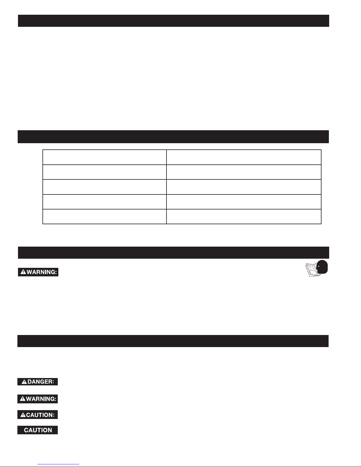
TABLE OF CONTENTS
PRODUCT SPECIFICATIONS ...................................................2
SAFETY INFORMATION ........................................................... 2
UNPACKING ..............................................................................4
Package Contents ............................................................... 5
Hardware ............................................................................ 5
ASSEMBLY .................................................................................6
Pivot Bolt ........................................................
Vertical Stabilizer and Rubber Feet ..................................... 6
Front Handle and Wheels .................................................... 7
Mounting Brackets and Workpiece Supports ..................... 7
Attaching Miter Saw to the Stand ....................................... 8
Using a Mounting Platform ................................................. 8
....
................ 6
PRODUCT SPECIFICATIONS
DESCRIPTION SPECIFICATIONS
Height (with mounting brackets) 36.06" (916mm)
Dimensions (folded for transport) 56.3”X 25.4” X 23.67” (1430mm X 645mm X 601mm)
Dimensions (extended for use) 57.83” X 25.4” X 36.1” (1469mm X 645mm X 916mm)
ADJUSTMENTS .........................................................................9
Workpiece Supports and Stop Plates ....................................... 9
Rail Extensions ........................................................................... 9
Collapsing the stand for transport
Mounting bracket clamping pressure
PARTS, SE
THREE-YEAR LIMITED WARRANTY ...................................... 10
REPLACEMENT PARTS ............................................................10
SERVICE AND REPAIRS ...........................................................10
RVICE OR WARRANTY ASSISTANCE ..................10
..............................................
..............................................99
Total Width with Fully Extended (114") (2896mm)
IMPORTANT SAFETY INSTRUCTIONS
CAREFULLY READ AND FOLLOW ALL WARNINGS AND INSTRUCTIONS ON YOUR
PRODUCT AND IN THIS MANUAL. SAVE THIS MANUAL. MAKE SURE ALL USERS
ARE FAMILIAR WITH ITS WARNINGS AND INSTRUCTIONS WHEN USING THE TOOL. Improper operation,
maintenance or modification of tools or equipment could result in serious injury and/or property damage.
DEFINITIONS – SAFETY SYMBOLS
This manual contains information that is important for you to know and understand. This information relates to
protecting YOUR SAFETY and PREVENTING EQUIPMENT PROBLEMS. To help you recognize this information, we
use the symbols below. Please read the manual and pay attention to these sections.
Indicates an imminently hazardous situation which, if not avoided, will result in death or
serious injury.
Indicates a potentially hazardous situation which, if not avoided, could result in death or
serious injury.
Indicates a potentially hazardous situation which, if not avoided, may result in minor or
moderate injury.
Used without the safety alert symbol indicates potentially hazardous situation which, if not avoided,
may result in property damage.
2
Page 3

GENERAL SAFETY RULES
WARNING FAILURE TO FOLLOW THESE RULES MAY RESULT IN SERIOUS PERSONAL INJURY.
FOR YOUR OWN SAFETY, READ AND UNDERSTAND THE INSTRUCTION MANUAL BEFORE OPERATING THE
•
PRODUCT STAND. KEEP WORK AREA CLEAN AND WELL LIT. Cluttered or poorly-lit work areas, surfaces and
benches can lead to accidents. Do not leave anything on stand when machine is in use. Allow enough room and
provide proper support for work piece and operation of the machine.
KEEP CHILDREN AND BYSTANDERS AWAY from work area.
•
WEAR PROPER APPAREL. DO NOT wear loose clothing, gloves, neckties, rings, bracelets, or other jewelry which
•
may get caught in moving parts. Nonslip protective footwear is recommended. Wear protective hair covering to
contain long hair.
EYE PROTECTION. All persons in work area should wear safety glasses with side shields. Everyday eyeglasses
•
with impact resistant lenses are not safety glasses. Eye equipment should comply with ANSI Z87.1 or CAN/CSA
Z94.3 standards.
HEARING PROTECTION. All people in work area should wear proper hearing protection consistent with noise
•
levels and exposure. Hearing equipment should comply with ANSI S3.19 standards.
DUST PROTECTION. Use of power tools can generate and/or disburse dust, which may cause serious and
•
permanent respiratory damage. Direct particles away from face and body. Always operate machines in well-
ventilated area and provide for proper dust removal. Use dust collection system whenever possible. Exposure
to dust may cause serious and permanent respiratory or other injury, including silicosis (a serious lung disease),
cancer, and death. Avoid breathing dust and avoid prolonged contact with dust. Allowing dust to get into your
mouth or eyes, or lay on your skin may promote absorption of harmful material. Use properly fitting NIOSH/
OSHA/MSHA approved respiratory protection appropriate for the dust exposure and wash exposed areas with
soap and water.
THIS PRODUCT WAS DESIGNED TO BE USED PRIMARILY AS A STAND FOR MITER SAWS. IT MAY BE USED
•
WITH PORTABLE PLANERS. DO NOT alter the stand, use it with other products, or for other purposes. The stand
will support 400 lbs., including both machine and work piece. Any misuse or abuse can result in product damage
or personal injury.
USE CARE WHEN ASSEMBLING, MOVING, RAISING OR LOWERING THE STAND to avoid the risk of pinching
•
hands and fingers.
PLACE THE STAND ON A FLAT AND LEVEL SURFACE to prevent rocking or tipping. Do not use the stand on an
•
uneven, unstable or slippery surface. Always check the stability of the stand before connecting machine to power
source.
DO NOT STAND ON THIS PRODUCT or use the support extensions as a ladder or scaffolding. It is unsafe to
•
climb, sit or stand on this product.
CHECK PRODUCT FOR DAMAGE. Before using stand, and after it has been dropped or damaged, check moving
•
and affected components of stand and any attached machines FOR ALIGNMENT, BINDING, BREAKAGE AND
ANY OTHER CONDITION THAT MAY AFFECT THE MACHINE’S PERFORMANCE AND THE STAND’S ABILITY
TO PROPERLY SUPPORT AND SECURE THE MACHINE. DO NOT USE A DAMAGED PRODUCT. A DAMAGED
PRODUCT SHOULD BE PROPERLY REPAIRED USING ONLY IDENTICAL REPLACEMENT PARTS.
CHECK ALL SUPPORTS TO CONFIRM THAT THEY ARE PROPERLY LOCKED IN PLACE BEFORE CONNECTING
•
MACHINE TO POWER SOURCE.
DISCONNECT MACHINE FROM POWER SOURCE BEFORE ATTACHING IT TO STAND, AND WHEN MACHINE IS
•
NOT IN USE.
PROPERLY MOUNT MACHINE AND ADJUST WORK PIECE SUPPORTS SO THE WORK PIECE(S) WILL BE
•
LEVEL WITH MACHINE TABLE.
PROPERLY SECURE THE MACHINE TO THE STAND BEFORE CONNECTING IT TO POWER SOURCE.
•
DO NOT ATTEMPT TO USE STAND FOR OPERATIONS INVOLVING AN AWKWARD OR OVERSIZED WORK PIECE
•
THAT COULD CAUSE THE STAND TO TIP OVER.
WHEN TRANSPORTING STAND, MAKE SURE IT IS PROPERLY SECURED TO PREVENT MOVEMENT AND
•
POSSIBLE DAMAGE.
SAVE THESE INSTRUCTIONS.
Refer to them often and use them to instruct others.
If stand is loaned to someone, also loan them these instructions.
3
Page 4

PROPOSITION 65 WARNING:
Dust created by power sanding, sawing, grinding, drilling, and other
construction activities may contain chemicals known to the state of California to cause cancer, birth
defects or other reproductive harm. Some examples are:
– Lead from lead-based paints
– Crystalline silica from bricks and cement and other masonry products
– Asbestos dust
– Arsenic and chromium from chemically-treated lumber
• Your risk from these exposures varies depending on how often you do this type of work. To reduce your exposure to
these chemicals: work in a well-ventilated area and work with approved safety equipment, such as dust masks that
are specially designed to filter out microscopic particles.
• Avoid prolonged contact with dust from power sanding, sawing, grinding, drilling, and other construction activities.
Wear protective clothing and wash exposed areas with soap and water
If you have any questions or concerns relative to the use of your tool or the contents of this manual,
stop using the tool and call DELTA® Power Equipment Corporation Customer Care at 1-800-223-7278.
UNPACKING
1. Remove all contents from the shipping carton.
2. Set aside the packing material; place the stand on the ground and lay out all loose parts and hardware.
3. Using the illustration below, locate and identify all parts and hardware to make sure they are all accounted for
before discarding packing material or beginning to assemble.
NOTE: If any part is missing or damaged, DO NOT attempt to assemble the product and call DELTA® Power
Equipment Corporation Customer Care at 1-800-223-7278.
4
Page 5
UNPACKING
PACKAGE CONTENTS DESCRIPTION (QTY)
1. Miter saw stand (1)
2. Handle (1)
3. Mounting bracket (2)
4. Workpiece support w/stop plate (2)
5. Vertical stabilizer (1)
6. Wheel (2)
7. Rubber Feet (2 Small and 2 Large)
8. Knob – Large (2)
HARDWARE DESCRIPTION (QTY)
1
3
2
4
• M6 Hex Locknut (2)
• M8 Locknut (2)
• M10 Locknut (2)
• M12 Hex Locknut (2)
• M6 x 50mm Slot Pan-Head
Screw (2)
• M8 x 20mm Self-Tapping
Screw (2)
• M10 X 55mm Hex Screw (2)
• M12 x 110mm Hex Head
Screw (2)
• M8 (ID) x 25mm (OD) X
3mm (thick) Flat Washer (2)
• M12 (ID) x 20mm (OD) x
2mm (thick) Flat Washer (2)
• M13 (ID) x 28mm (OD) x
2.8mm (thick) Flat Washer
(2)
• Wheel shaft M8*93L Hex
shoulder screw (2)
• M8 x 55mm hex bolt (4)
• M8 washer (4)
• M8 hex nut (4)
NOTE: All hardware uses
right-handed threads.
5
6
7 8
5
Page 6
ASSEMBLY
Tools Required for Assembly (not included):
Phillips screwdriver, socket set, and an
adjustable wrench.
C
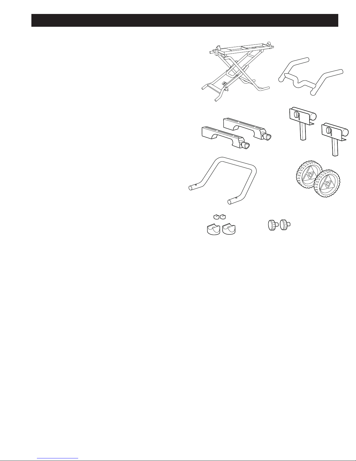
PIVOT BOLT
1. Lay the stand on its side.
2. Pull the rear folding support (A) toward the
handle tube openings (B) in order to align the
holes in the rear folding support and front
folding support.
3. Insert an M12 x 110mm hex bolt (C) through
the front folding leg. Place an M12 washer (D)
between the front and rear supports and feed
the bolt through the washer and rear support.
4. Secure with an M12 hex nut. The nut should be
snug but not over-tight.
5. Place the stand upright. The holes in the
supports on the opposite side should be nearly
aligned. Repeat Steps 3 and 4 to secure other
side.
D
Align holes
A
B
VERTICAL STABILIZER AND
RUBBER FEET
1. Place the stand on its side.
2. Insert the vertical stabilizer (A) into the ends
of the rear folding supports (B) with the end of
the stabilizer angling up. Align the holes in the
stabilizer and supports.
3. Attach the larger rubber feet (C) to the bottom of
the vertical stabilizer by feeding an M10 x 55mm
hex bolt through the bottom of the feet. Secure
with an M10 hex nut, remembering to rotate it
clockwise to tighten.
4. Attach the smaller rubber pads (D) to the end of
the vertical stabilizer using two M6 x 50mm pan
head bolts and M6 locknuts.
A
D
C
B
6
Page 7
ASSEMBLY
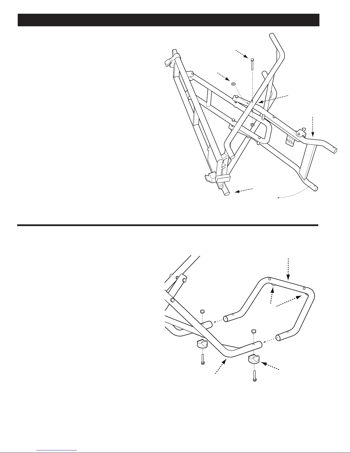
FRONT HANDLE AND WHEELS
1. Attach handle (A) by inserting the tubes into the
top of the front folding supports. The handle
should be angled down.
2. Align holes and secure using two M8 x 20mm
self-tapping screws (B) and Phillips head
screwdriver.
3. Place a M13 (ID) x 28mm (OD) washer on each of
the fixed axles (C).
4. Slide the wheels (D) onto the axle with the wheel
collar facing in. Place a M8.2 (ID) x 25mm (OD)
washer onto the end of each axle.
5. Secure with an M8 lock nut. Rotate the nut
clockwise to tighten. Do not over-tighten.
B
B
A
C
D
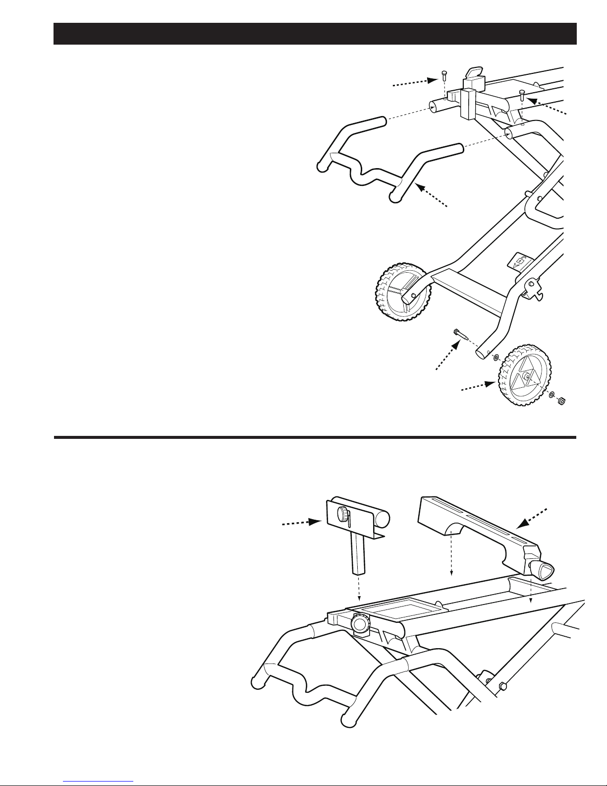
MOUNTING BRACKETS AND WORKPIECE SUPPORTS
1. Place the mounting brackets (A) onto
the front and rear rails by engaging
the front end of the bracket on the
rail first, then lowering the rear end
over the rail.
2. Insert the workpiece supports (B)
as shown with the clamping knobs
facing out.
B
A
7
Page 8
ASSEMBLY
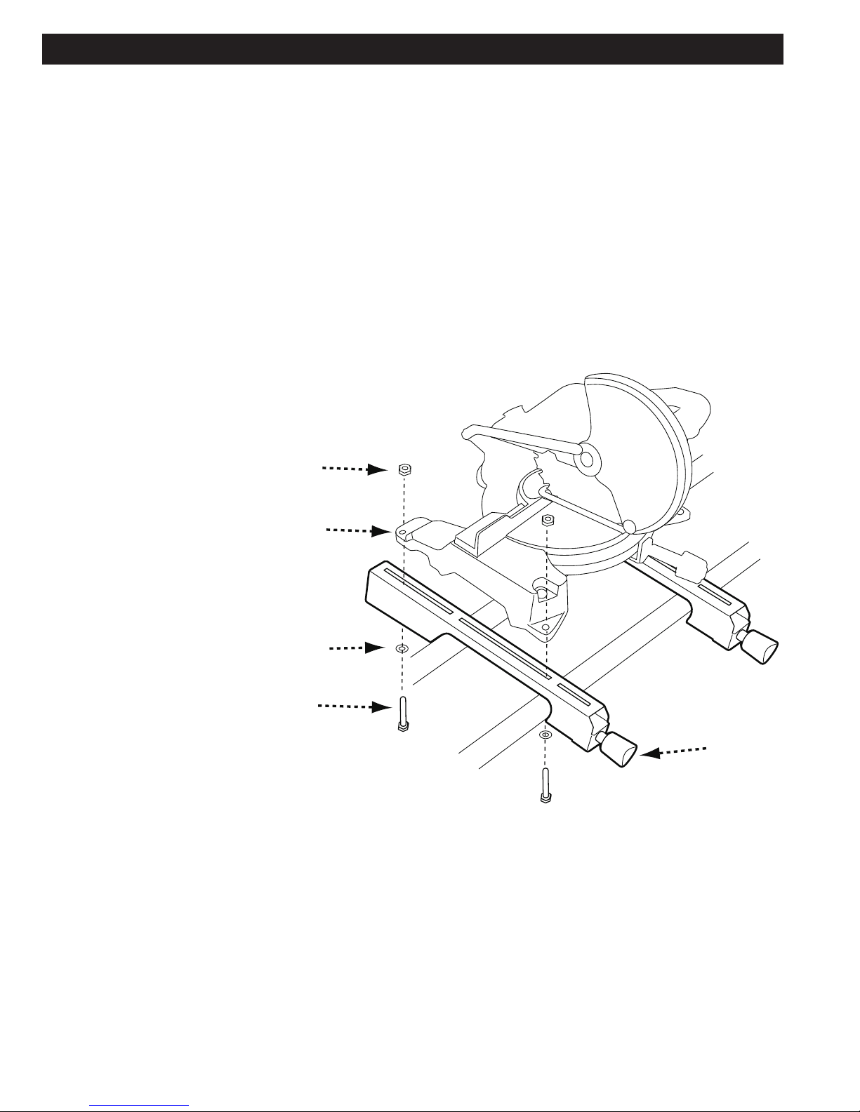
ATTACHING THE MITER SAW TO THE STAND
NOTE: This stand comes with four M8 x 55mm bolts
with M8 washers and hex nuts. If your saw requires a
different number or size of mounting bolt, use hardware
that will properly secure your saw. Make sure bolt ends
do not extend above the saw table.
NOTE: The DELTA 36-267 miter saw stand is designed
to work with virtually all miter saws. In the event that
the mounting holes on the saw do not line up with the
slots in the mounting brackets, skip to the next section,
“Using a Mounting Platform”
1. Ensure the saw is disconnected from the power
source and the blade and arm are locked in the
down position.
2. With both mounting brackets attached to the rails,
lock one of the mounting brackets in position by
turning the lock knob (A) clockwise.
3. Place the saw on top of the mounting brackets so
that the mounting holes in the saw (B) align with the
slots in the stationary bracket.
NOTE: The exact location of the mounting holes may
vary from saw to saw. Figure 6 is given as an example.
4. Feed an M8 x 55mm hex bolt (C) fitted with an M8
washer (D) up through the slots in the bracket and
through the mounting holes in the saw. Secure
with an M8 hex nut (E).
5. Adjust the other bracket under the saw so that
the brackets slots align with the saw’s mounting
holes. Lock bracket in place by turning lock knob
clockwise.
6. Repeat Step 4 to secure saw to second mounting
bracket.
E
B
D
C
USING A MOUNTING PLATFORM
Should the existing mounting holes in your saw not fit
the slots in the mounting brackets, it will be necessary
to mount a wooden platform to the brackets then mount
the saw to the platform.
The platform can be made from any rectangular or
square piece of wood scrap that is at least ½-inch thick
and large enough to extend beyond the saw’s base by at
least an inch.
1. Unlock and remove mounting brackets from the rails.
Place them upside down on the top of board so that
they are centered top to bottom and aligned with the
edge of the board.
2. Use a pencil to mark the midpoint in the top and
bottom slots on each bracket.
A
3. Remove the brackets and drill a ¼-inch hole at each
mark.
4. Place the saw on the platform so that it is centered
on the board. Mark the mounting holes with a pencil.
5. Remove the saw and use a 5/16 - inch drill bit to drill
the holes in the platform.
6. Mount the saw to the board using bolts, washers and
nuts (not provided).
7. Follow Steps 4-6 in above section (Attaching the
Miter Saw to the Stand) to secure the platform to the
brackets.
8
Page 9
ADJUSTMENTS
WORKPIECE SUPPORTS AND
STOP PLATES
The workpiece supports hold the workpiece level with the stop
plates, preventing it from moving side to side. To raise or lower the
1.
Loosen the support lock knob (A).
2.
Position the supports so they are level and at the
desired height and re-tighten the lock knob.
To position the stop plate on the workpiece supports:
1.
Loosen the stop plate lock knob (B).
2.
Position the stop plate at the desired height and
re-tighten the lock knob.
RAIL EXTENSIONS
The DELTA 36-267 Miter Saw Stand features left and right rail
extensions to accomodate longer work pieces. To extend the right or
left extensions:
1.
Depress the rail lock (A) and pull the rail out to
the desired length.
2.
Release the lock.
B
A
A
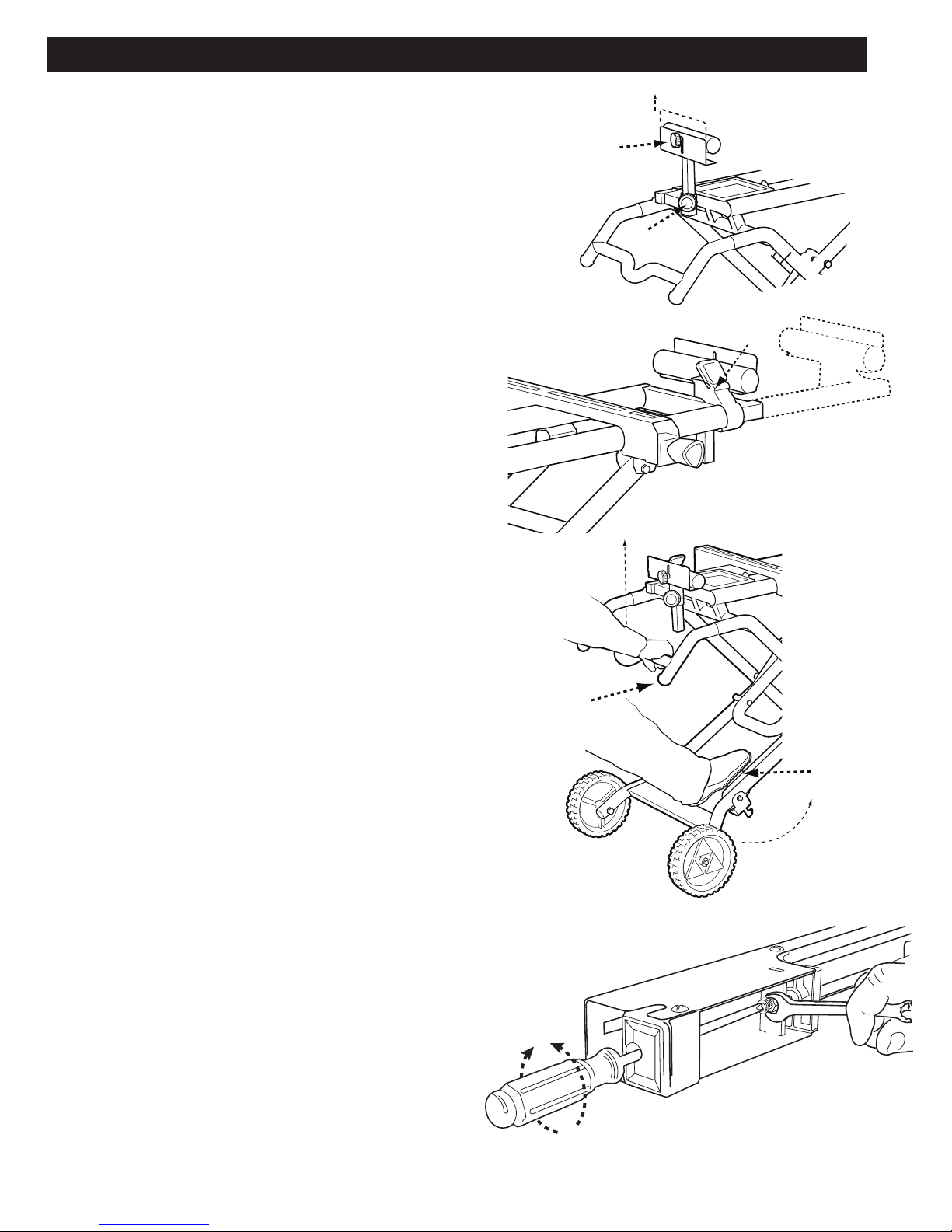
COLLAPSING THE STAND FOR
TRANSPORT
The stand folds down for easy transport and can be collapsed
and moved with the saw mounted. To fold the stand for
transport:
1.
Ensure the saw is unplugged and cord wrapped and the
mounting brackets are secured on the rails and locked down.
2.
Grasping the handle (A) from underneath, depress the foo
pedal lock (B) and slowly lift up on the handle.
3.
Continue to raise the handle, guiding the stand forward and
up, until the support legs click into place.
4.
You can now lower the folded stand to a comfortable position
for transport.
5.
To redeploy the stand and saw, grasp the handle, depress
the foot pedal and slowly guide the handle end of the stand
down and back until you hear the support legs click into
place. Make sure the lock has clicked into place before using
it for any cutting operation.
MOUNTING BRACKET CLAMPING
PRESSURE
t
A
B
Adjust mounting bracket pressure as shown.
9
Page 10

PARTS, SERVICE OR WARRANTY ASSISTANCE
All DELTA® machines and accessories are manufactured to high quality standards and are serviced by a network
of Authorized Service Centers. To obtain additional information regarding your DELTA® quality product or to obtain
parts, service, warranty assistance, or the location of the nearest service center, please call 1-800-223-7278.
Two Year Limited New Accessories Warranty
DELTA will repair or replace, at its expense and at its option, any machine accessory which in normal use
has proven to be defective in workmanship or material, provided that the customer returns the product
prepaid to a DELTA factory service center or authorized service station with proof of purchase of the
product within two years and provides DELTA with reasonable opportunity to verify the alleged defect by
inspection. For all refurbished DELTA product, the warranty period is 180 days. DELTA may require that
electric motors be returned prepaid to a motor manufacturer’s authorized station for inspection and repair
or replacement. DELTA will not be responsible for any asserted defect which has resulted from normal wear,
misuse, abuse or repair or alteration made or specifically authorized by anyone other than an authorized
DELTA service facility or representative. Under no circumstances will DELTA be liable for incidental or
consequential damages resulting from defective products. This warranty is DELTA ’s sole warranty and sets
forth the customer’s exclusive remedy, with respect to defective products; all other warranties, express or
implied, whether of merchantability, fitness for purpose, or otherwise, are expressly disclaimed by DELTA.
For further detail of warranty coverage and warranty repair information, visit www.DeltaMachinery.com or
call 1-800-223-7278. This warranty gives you specific legal rights and you may have other rights which vary
in certain states or provinces.
REPLACEMENT PARTS
Use only identical replacement parts. For a parts list or to order parts, visit our website at www.DeltaMachinery.com/service. You
can also order parts from your nearest Authorized Warranty Service Center or by calling Technical Service Manager at 1-800-2237278 to receive personalized support from one of our highly-trained representatives.
FREE WARNING LABEL REPLACEMENT
If your warning labels become illegible or are missing, call
1-800-223-7278
for a free replacement.
SERVICE AND REPAIRS
All quality tools will eventually require servicing and/or replacement of parts. For information about DELTA®
Power Equipment Corporation, its factory-owned branches, or to locate an Authorized Warranty Service Center,
visit our website at www.DeltaMachinery.com/service or call Customer Care at 1-800-223-7278. All repairs
made by our service centers are fully guaranteed against defective material and workmanship. We cannot
guarantee repairs made or attempted by others. By calling this number you can also find answers to most
frequently asked questions 24 hours/day.
You can also write to us for information at DELTA® Power Equipment Corporation, 99 Roush St., Anderson, SC
29625-3113 - Attention: Technical Service Manager.
10
Page 11

SOMMAIRE
:
:
MISE EN GARDE:
MISE EN GARDE:
SPECIFICATIONS DU PRODUIT ............................................ 11
INSTRUCTIONS DE SECURITE IMPORTANTES ..................11
DEBALLAGE ............................................................................13
Contenu des cartons ......................................................... 14
Accessoires de montage .................................................. 14
ASSEMBLAGE ...................
Boulon de pivot ................................................................ 15
Stabilisateur vertical et pieds en caoutchouc ................... 15
Poignées avant et roues .................................................... 16
Fixations de montage et supports de pièces de travail .... 16
Fixer la scie à onglet sur l'établi .............................
Utiliser une plateforme de montage .................................. 17
......................................................15
........... 17
SPECIFICATIONS DU PRODUIT
DESCRIPTION SPECIFICATION
Hauteur (avec les
Dimensions (plié pour le transport) 54.3”X 25.4” X 23.67” (1380mm X 645mm X 601mm)
Dimensions (déplié pour l'utilisation) 57.83” X 25.4” X 36.1” (1469mm X 645mm X 916mm)
ns de montage) 36.06" (916mm)
REGLAGES ..............................................................................18
Supports et plaques de butée des pièces de travail ............... 18
Rallonges de rail ....................................................................... 18
Plier l'établi pour le transporter
Pression de support de montage
ASSISTANCE PIECES DETACHEES, SERVICE APRES-
VENTE OU GARANTIE ............................................................20
GARANTIE LIMITEE DE TROIS ANS .....................................20
PIECES DE RECHANGE .........................................................20
SERVICE APRES-VENTE ET REPARATION ..........................20
................................................. 19
...
.................................... 19
Largeur totale quand totalement déplié (114") (2896mm)
INSTRUCTIONS DE SECURITE IMPORTANTES
AVERTISSEMENT
UTILISATEURS LES CONNAISSENT LORS DE L'UTILISATION DE CE PRODUIT. Une utilisation, un entretien ou une
modification impropre des outils ou équipements pourrait entraîner de graves blessures ou des dommages
matériels.
LIRE TOUS LES AVERTISSEMENTS ET INSTRUCTIONS D'UTILISATION PRESENTS
SUR VOTRE PRODUIT ET DANS CE MANUEL. S'ASSURER QUE TOUS LES
SYMBOLES DE SECURITE – DEFINITIONS
Ce manuel contient des informations importantes que vous devriez bien assimiler. Ces informations portent
sur VOTRE SECURITE et LA PREVENTION DES PROBLEMES D’EQUIPEMENT. Pour vous aider à identifier ces
informations, nous utilisons les symboles ci-dessous. Veuillez lire attentivement ce manuel en portant une attention
particulière à ces sections.
Indique une situation dangereuse imminente qui, si elle n’est pas évitée, causera la mort ou des
blessures graves.
AVERTISSEMENT
Indique une situation potentiellement dangereuse qui, si elle n’est pas évitée, pourrait causer la mort
ou des blessures graves.
Indique une situation potentiellement dangereuse qui, si elle n’est pas évitée, pourrait causer des
blessures mineures ou modérées.
utilisé sans le triangle de sécurité, indique une situation potentiellement dangereuse qui, si elle n'est
pas évitée, pourrait causer des dommages matériels.
11
Page 12

REGLES GENERALES DE SECURITE
AVERTISSEMENT:
LE NON RESPECT DE CES REGLES PEUT CAUSER DES BLESSURES SERIEUSES.
POUR SA SECURITE PERSONNELLE, LIRE LE MANUEL D’UTILISATION AVANT D'UTILISER L'ETABLI. GARDER
•
L'AIRE DE TRAVAIL PROPRE ET BIEN ECLAIREE. Des zones, surfaces ou bancs de travail encombrés et mal
éclairés favorisent les accidents. Débarrasser l'établi lors de l'utilisation de la machine. Conserver suffisamment
d'espace libre lors de l'utilisation de la machine et supporter de manière appropriée les pièces de travail.
GARDER LES ENFANTS ET LES VISITEURS A DISTANCE de l'aire de travail.
•
PORTER UNE TENUE APPROPRIEE. PAS DE cravates, gants, vêtements amples, bagues, bracelets ni autres
•
bijoux qui peuvent être pris dans les pièces mobiles. L'usage de chaussures antidérapantes est recommandé.
Placer les cheveux longs sous une protection.
PROTECTIONS OCULAIRES. Toutes les personnes situées dans la zone de travail doivent porter des lunettes
•
de sécurité pourvues de protections latérales. Les lunettes ordinaires NE sont PAS des lunettes de sécurité. Les
dispositifs de protection oculaires doivent être conformes aux normes ANSI Z87.1 ou CAN/CSA Z94.3.
PROTECTIONS AUDITIVES. Toutes les personnes situées dans la zone de travail doivent porter des protections
•
auditives appropriées au niveau du bruit et à l'exposition à celui-ci. Les protection auditives doivent être
conformes aux normes ANSI S3.19.
PROTECTION CONTRE LA POUSSIERE. L'utilisation d'outils électriques peut produire et/ou disperser de la
•
poussière ce qui peut entraîner des troubles respiratoires. Diriger les particules loin du visage et du corps.
Toujours utiliser l'outil dans un espace bien ventilé et prévoir l'évacuation de la poussière. Utiliser un système
de dépoussiérage si possible. L'exposition à la poussière peut causer des problèmes de santé graves et
permanents, respiratoires ou autres, tels que la silicose (maladie pulmonaire grave) et le cancer, et même la mort
de la personne affectée. Éviter de respirer de la poussière et de laisser la peau en contact prolongé avec celleci. En laissant la poussière pénétrer dans les yeux ou la bouche, ou en la laissant reposer sur la peau, il existe
un risque de promouvoir l'absorption de substances toxiques. Toujours porter des dispositifs de protection
respiratoire de taille appropriée homologués NIOSH/OSHA, conçus pour l'exposition à la poussière et laver à
l'eau et au savon les surfaces corporelles exposées.
CE PRODUIT A ETE CONCU POUR ETRE TOUT D'ABORD UTILISE COMME ETABLI POUR UNE SCIE A ONGLET.
•
IL PEUT ETRE UTILISE AVEC DES RABOTS PORTATIFS. NE PAS modifier l'établi, l'utiliser avec d'autres produits,
ou pour d'autres buts. L'établi peut supporter jusqu'à 400 livres, y compris la machine et la pièce de travail. Tout
excès ou mauvaise utilisation peut endommager le produit ou blesser.
FAIRE ATTENTION LORS DU MONTAGE, DEPLACEMENT, ELEVATION OU ABAISSEMENT DE L'ETABLI pour
•
éviter de vous pincer les mains et les doigts.
PLACER L'ETABLI SUR UNE SURFACE PLANE ET D'APLOMB pour l'empêcher de vaciller ou de basculer. Ne
•
pas utiliser l'établi sur une surface glissante, non plane ou pas d'aplomb. Toujours vérifier la stabilité de l'établi
avant de brancher la machine à l'alimentation électrique.
NE PAS SE TENIR DEBOUT SUR CE PRODUIT ou utiliser les rallonges de support comme échelle ou
•
échafaudage. Il est dangereux de monter, s'asseoir ou se tenir debout sur produit.
INSPECTER LE PRODUIT POUR DECELER TOUT DOMMAGE. Avant d'utiliser l'établi et après son éventuel chute
•
ou endommagement, vérifier les éléments mobiles et ceux endommagés de l'établi et toute machine en contact
POUR VERIFIER LES ALIGNEMENTS, ATTACHES, BRIS OU TOUTE AUTRE CONDITION PREJUDICIABLE
POUVANT AFFECTER LES PERFORMANCES DE LA MACHINE ET LA CAPACITE DE L'ETABLI A SUPPORTER
DE FACON SURE LA MACHINE. NE PAS UTILISER UN PRODUIT ENDOMMAGE. TOUT PRODUIT ENDOMMAGE
DOIT ETRE REPARE EN N'UTILISANT QUE DES PIECES DE RECHANGE IDENTIQUES.
VERIFIER QUE LES FIXATIONS SONT BIEN EN PLACE AVANT DE BRANCHER LA MACHINE.
•
DEBRANCHER LA MACHINE AVANT DE LA FIXER SUR SON ETABLI OU SI ELLE N'EST PAS UTILISEE.
•
INSTALLER LA MACHINE ET REGLER LES SUPPORT DE PIECES DE TRAVAIL DE MANIERE APPROPRIEE DE
•
SORTE QUE LES PIECES DE TRAVAIL SOIENT D'APLOMB AVEC L'ETABLI DE MACHINE.
BIEN FIXER LA MACHINE SUR L'ETABLI AVANT DE LA BRANCHER SUR L'ALIMENTATION ELECTRIQUE.
•
NE PAS ESSAYER D'UTILISER L'ETABLI AVEC DES PIECES DE TRAVAIL INHABITUELLES OU DE TROP
•
GRANDE TAILLE POUVANT ENTRAINER LE BASCULEMENT DE L'ETABLI.
LORS DU TRANSPORT DE L'ETABLI, S'ASSURER QU'IL EST BIEN ATTACHE POUR EVITER TOUT
•
DEPLOIEMENT ET POSSIBLE DOMMAGE.
CONSERVER CES INSTRUCTIONS.
Les consulter souvent et les partager avec les autres utilisateurs.
Joindre ces instructions à l'établi en cas de prêt de celui-ci.
12
Page 13

PROPOSITION 65 DE LA CALIFORNIE
:
AVERTISSEMENT
reproductrices. Voici quelques exemples de ces produits chimiques:
– Le plomb contenu dans les peintures à base de plomb
– La silice cristalline de la brique, du ciment et d'autres produits de maçonnerie
– La poussière d'amiante
– L'arséniate de cuivre et de chrome provenant du bois traité chimiquement (CCA)
• Les risques reliés à l'exposition à ces poussières varient selon la fréquence à laquelle l'utilisateur travaille avec
ce type de matériaux. Pour réduire l'exposition à ces produits chimiques, travailler dans un endroit bien ventilé et
porter un équipement de sécurité approuvé comme un masque anti poussières conçu spécialement pour filtrer les
particules microscopiques.
• Éviter tout contact prolongé avec les poussières produites par des activités de ponçage, sciage, meulage, perçage
et autres activités de construction. Porter des vêtements de protection et laver à l'eau et au savon les surfaces
corporelles exposées.
Pour toute question relative à l'utilisation de cet outil ou au contenu de ce manuel, veuillez tout d'abord arrêter
d'utiliser l'outil et appeler le Service Clientèle de DELTA® Power Equipment Corporation au 1-800-223-7278.
Certaines poussières produites par les activités de ponçage, sciage, meulage, perçage et
autres activités de construction contiennent des produits chimiques connus de l'État de Californie
pour causer le cancer, des anomalies congénitales ou d'autres problèmes liés aux fonctions
DEBALLAGE
1. Retirer tous le contenu des cartons de transport.
2. Mettre de côté les cartons d'emballage. Placer l'établi sur le sol et étaler sur le sol tous les accessoires de
montage et les pièces détachées.
3. En s'aidant du dessin ci-dessous, localiser, identifier et s'assurer de la présence de tous les accessoires de
montage et les pièces détachées avant de jeter les emballages ou de commencer l'assemblage.
NOTE: Si un élément manque ou est endommagé, NE PAS essayer d'assembler le produit et appeler le Service
Clientèle de DELTA® Power Equipment Corporation au 1-800-223-7278.
13
Page 14

DESCRIPTION DU CONTENU DES
CARTONS (QTE)
1. Établi pour scie à onglet (1)
2. Poignée (1)
3. Fixations de montage (2)
4. Supports de pièce de travail avec plaque de
butée (2)
5. Stabilisateur vertical (1)
6. Roues (2)
7. Pieds en caoutchouc (2 petits et 2 grands)
8. Boutons (2)
DESCRIPTION DE LA VISSERIE
D'ASSEMBLAGE
DEBALLAGE
1
3
2
4
• Écrou de blocage
hexagonal M6 (2)
• Écrou de blocage M8 (2)
• Écrou de blocage M10 (2)
• Écrou de blocage
hexagonal M12 (2)
• Vis à tête cylindrique
fendue M6 x 50mm (2)
• Vis auto taraudeuse M8 x
20mm (2)
• Vis hexagonale M10 x
55mm (2)
• Vis à tête hexagonale M12
x 110mm (2)
• Rondelle plate M8 (ID)
x 25mm (OD) x 3mm
(épaisseur) (2)
• M12 (ID) x 20mm (OD) x
2mm (Rondelle plate M12
(ID) x 20mm (OD) x 2mm
(épaisseur) (2)
• Rondelle plate M13 (ID)
x 28mm (OD) x 2,8mm
(épaisseur) (2)
• Vis à épaulement
hexagonale M8*93L axe de
roue (2)
• boulon hexagonal M8 x
55mm (4)
• rondelle M8 (4)
• écrou hexagonal M8 (4)
NOTE: Tous ces éléments
utilisent des filetages à droite.
5
6
7 8
14
Page 15

ASSEMBLAGE
Outils (non inclus) nécessaires pour
l'assemblage : un tournevis Phillips, un jeu de
douille, et une clé réglable.
C
BOULON DE PIVOT
1. Coucher l'établi sur son côté.
2. Tirer le support pliable arrière (A) vers les
ouvertures des tubes de la poignée (B) de
façon à aligner les trous du support pliable
arrière et du support pliable avant.
3. Insérer un boulon hexagonal M12 x 110 (C)
au travers du pied pliable avant. Placer une
rondelle M12 (D) entre les supports avant et
arrière et engager le boulon au travers de la
rondelle et du support arrière.
4. Fixer avec un écrou hexagonal M12. Le serrer
mais pas trop.
5. Placer l'établi debout. Les trous du support du
côté opposé devraient être presque alignés.
Répéter les étapes 3 et 4 pour fixer l'autre
côté.
D
Aligner les trous
A
B
STABILISATEUR VERTICAL ET
PIEDS EN CAOUTCHOUC
1. Coucher l'établi sur son côté.
2. Insérer le stabilisateur vertical (A) dans les
extrémités des supports pliables arrières (B)
avec les extrémités du stabilisateur formant
un angle vers le haut. Aligner les trous du
stabilisateur et des supports.
3. Attacher les pieds en caoutchouc les plus
grands (C) à la base du stabilisateur vertical
en faisant passer un boulon hexagonal M10 x
55mm au travers de la base du pied. Fixer avec
un écrou hexagonal M10, en se rappelant de le
tourner dans le sens horaire pour le serrer.
4. Attacher les pieds en caoutchouc les plus petits
(D) à l'extrémité du stabilisateur vertical à l'aide
de deux vis à tête cylindrique fendue M6 x 50mm
et écrous de blocage M6.
A
D
C
B
15
Page 16

ASSEMBLAGE
POIGNEE AVANT ET ROUES
1. Attacher la poignée (A) en insérant les tubes
dans le sommet des supports pliables avant. La
poignée devrait former un angle vers le bas.
2. Aligner les trous et fixer à l'aide de deux vis auto
taraudeuse M8 x 20mm (B) et d'un tournevis à
tête Phillips.
3. Placer une rondelle M13 (ID) x 28mm (OD) sur
chaque axe fixe (C).
4. Faire glisser les roues (D) sur les axes avec
l'intérieur des roues se faisant face. Placer une
rondelle M8,2 (ID) x 25mm (OD) sur l'extrémité de
chaque axe.
5. Fixer avec un écrou de blocage M8. Tourner
l'écrou dans le sens horaire pour le serrer. Ne pas
trop le serrer.
B
B
A
C
D
SUPPORTS DE MONTAGE ET SUPPORTS DE PIECE DE TRAVAIL
1. Placer les fixations de montage
(A) sur les rails avant et arrière en
engageant d'abord l'extrémité
avant du support sur le rail, puis en
abaissant l'extrémité arrière sur le
rail.
2. Insérer les supports de pièce de
travail (B) tel illustré avant les
boutons de serrage vers l'extérieur.
B
A
16
Page 17

ASSEMBLAGE
FIXER LA SCIE À ONGLET SUR L'ÉTABLI
NOTE: Cet établi est livré avec quatre boulons M8 x
55mm, des rondelles M8 et des écrous hexagonaux. Si
votre scie nécessite un nombre différent de boulons de
montage, utilisez du matériel qui fixera la scie de façon
appropriée. S'assurer que les extrémités des boulons ne
dépassent pas de l'établi de scie.
NOTE: L'établi pour scie à onglet DELTA 36-267 est
conçu pour recevoir théoriquement toutes scies
à onglet. Dans le cas où les trous de montage ne
s'alignent pas sur les rainures des fixations de montage,
passer à la section suivante, 'Utiliser une plateforme de
montage'
1. S'assurer que la scie est débranchée de
l'alimentation électrique et que la lame et le bras
sont verrouillés en position basse.
2. Avec les deux fixations de montage attachés aux
rails, verrouiller l'une des fixations de montage en
position en tournant le bouton de verrouillage (A)
dans le sens horaire.
3. Placer la scie sur les fixations de montage de sorte
que les trous de montage (B) s'alignent avec les
rainures de la fixation fixe.
NOTE : L'emplacement des trous de montage peut
varier en fonction de la scie. La Figure 6 est un
exemple.
4. Engager vers le haut un boulon hexagonal M8 x
55mm (C) muni d'une rondelle M8 (D) au travers
des rainures dans la fixation et du trou de montage
dans la scie. Fixer avec un écrou hexagonal M8
(E).
5. Ajuster l'autre fixation sous la scie de sorte que les
rainures des fixations s'alignent sur les trous de
montage de la scie.
Verrouiller la fixation en position en tournant le bouton
de verrouillage dans le sens horaire.
6. Répéter l'étape 4 pour fixer la scie à la seconde
fixation de montage.
E
B
D
C
UTILISER UNE PLATEFORME DE MONTAGE
Si les trous de montage existants de votre scie
ne correspondent pas aux rainures des fixations
de montage, il sera alors nécessaire de monter une
plateforme en bois sur les fixations et de monter votre
scie sur la plateforme.
La plateforme peut être réalisée à partir de n'importe
quel morceau de rebut de bois rectangulaire ou
carré d'une épaisseur minimale de ½'' (13mm) et
suffisamment large pour s'étendre au-delà de la base de
la scie d'au moins un pouce (26mm)..
1. Déverrouiller et retirer les fixations de montage
des rails. Les placer sens dessus dessous sur le
sommet de la planche de sorte qu'ils soient centrés
du sommet à la base et alignés sur le bord de la
planche.
A
17
Page 18

ASSEMBLAGE
2. Marquer le milieu dans les rainures du sommet et de
la base de chaque fixation à l'aide d'un crayon.
3. Retirer les fixations et percer un trou de ¼'' sur
chaque marque.
4. Placer la scie sur la plateforme de sorte qu'elle
soit centrée sur la planche. Marquer les trous de
montage à l'aide d'un crayon.
REGLAGES
SUPPORTS ET PLAQUES DE
BUTÉE DES PIÈCES DE TRAVAIL
Les supports de pièces de travail maintiennent le
niveau de la pièce de travail à l'aide des plaques de
butées en l'empêchant de bouger. Pour monter ou
abaisser les supports:
1. Desserrer le bouton de verrouillage du support (A).
2. Placer les supports de sorte qu'ils soient de niveau
et à la hauteur désirée, puis resserrer le bouton de
verrouillage.
Pour placer la plaque de butée sur les supports de
pièce de travail:
1. Desserrer le bouton de verrouillage de la plaque de
butée (B).
2. Placer la plaque de butée à la hauteur désirée, puis
resserrer le bouton de verrouillag.
5. Retirer la scie et percer les trous dans la plateforme à
l'aide d'une mèche de 5/16''.
6. Fixer la scie sur la planche à l'aide de boulons,
rondelles et écrous (non inclus).
7. Suivre les étapes 4-6 de la section précédente (Fixer
la scie à onglet sur l'établi) pour fixer la plateforme
aux fixations.
B
A
RALLONGES DE RAIL
L'établi pour scie à onglet DELTA 36-267 comprend
des rallonges gauche et droite de rail pour permettre
le travail de pièces plus longues. Pour étendre les
rallonges gauche et droite:
1. Depress the rail lock (A) and pull the rail out to the
Appuyer sur le dispositif de verrouillage du rail (A) et
tirer le rail jusqu'à la longueur désirée.
2. Relâcher le dispositif de verrouillage.
A
18
Page 19

REGLAGES
PLIER L'ÉTABLI POUR LE
TRANSPORTER
L'établ i se repli e pour être tra nsporté f acileme nt e t ce
éventuellement avec la scie installée dessus. Pour plier l'établi pour
le transporter:
1. S'assurer que la scie est débranchée et le fil électrique enroulé,
et que les fixations de montage sont fixées sur les rails et
verrouillées.
2. Saisir la poignée (A) par en dessous et appuyer sur le dispositif
de verrouillage de la pédale (B), puis élever doucement la
poignée.
3. Continuer à élever la poignée en guidant l'établi vers l'avant et le
haut jusqu'à ce que les pieds de support s'enclenchent.
4. Vous pouvez maintenant abaisser l'établi plié jusqu'à une
position confortable pour le transport.
5. Pour déplier l'établi et la scie, saisir la poignée, appuyer
pédale à pied et guider doucement l'extrémité de la poignée
de l'établi vers le bas et l'arrière jusqu'à entendre les pieds de
support s'enclencher. S'assurer que le dispositif de verrouillage
soit enclenché avant d'utiliser l'établi avec la scie.
sur la
A
B
PRESSION DE SUPPORT DE MONTAGE
Ajustez la pres sion de su pport de m ontage comm e indiq ué .
19
Page 20

ASSISTANCE PIECES DETACHEES, SERVICE APRES-VENTE OU GARANTIE
Tous les accessoires et machines DELTA® sont fabriqués en respectant de hauts standards de qualité et le service
après-vente est effectué par un réseau de Centres SAV Agréés. Pour obtenir des informations supplémentaires sur
vos produits DELTA® ou obtenir des pièces, bénéficier du SAV ou de la garantie, ou connaître le centre SAV le plus
proche, appeler le 1-800-223-7278.
Garantie Nouveau Accessoires Limitée à Deux Ans
Delta réparera ou remplacera, à ses frais et à sa discrétion, tout accessoire de machine qui, dans des
circonstances d'utilisation normale, s'est avéré défectueux en raison de défauts de matériau ou de
fabrication, à condition que le client retourne le produit (transport payé d'avance) à un centre de réparation
d'usine DELTA ou à un centre de réparation agréé accompagné d'une preuve d'achat et dans les deux
ans de la date d'achat du produit, et fournisse à DELTA une opportunité raisonnable de vérifier le défaut
présumé par une inspection. La période de garantie des produits DELTA remis à neuf est de 180 jours.
DELTA peut demander que les moteurs électriques soient retournés (transport payé d'avance) a un
centre de réparation agréé du fabricant du moteur en vue d'une inspection, d'une réparation ou d'un
remplacement. DELTA ne peut être tenu pour responsable des défauts résultants d'une usure normale,
d'une mauvaise utilisation, d'un abus, d'une réparation ou d'une modification du produit, sauf en cas
d'autorisation spécifique d'un centre de réparation ou d'un représentant DELTA agréé. DELTA ne peut être
en aucune circonstance tenu pour responsable des dommages accidentels ou indirects résultant d'un
produit défectueux. Cette garantie constitue la seule garantie de DELTA et le recours exclusif des clients en
ce qui concerne les produits défectueux ; toutes les autres garanties, expresses ou implicites, de qualité
marchande, d'adéquation a un usage particulier, ou autre, sont expressément déclinées par DELTA. Pour
obtenir de plus amples renseignements sur les pièces ou les réparations couvertes par la présente garantie,
visiter le site www.DeltaMachinery.com ou appeler le 1-800-223-7278. Cette garantie confère des droits
légaux particuliers à l’acheteur, mais celui-ci pourrait aussi bénéficier d’autres droits variant d’un état ou
d’une province à l’autre.
PIECES DE RECHANGE
Utiliser seulement des pièces de rechange identiques. Pour obtenir une liste des pièces de rechange ou pour en commander,
consulter notre site Web www.DeltaMachinery.com. Il est aussi possible de commander des pièces auprès d’un Centre de
Réparation sous Garantie Agréé ou en appelant le Directeur du Service Technique au 800-223-7278 pour recevoir un soutien
personnalise de l’un de nos représentants hautement qualifiés.
REMPLACEMENT GRATUIT D'ETIQUETTES D'AVERTISSEMENT
Si vos étiquettes d'avertissement deviennent illisibles ou sont manquantes, appelez le 1-800-223-7278 pour obtenir une
étiquette de remplacement gratuite.
SERVICE APRES-VENTE ET REPARATION
All quality tools will eventually require servicing and/or replacement of parts. For information about DELTA®
Tous les outils de qualité finissent par demander un entretien ou un changement de pièce. Pour de plus
amples renseignements sur nos Centres de Réparation sous Garantie Agréés, consulter notre site Web www.
DeltaMachinery.com ou appeler le Directeur du Service Technique au 800-223-7278. Toutes les réparations
effectuées dans nos centres de réparation sont entièrement garanties contre les défauts de matériaux et de
main-d'œuvre. Nous ne pouvons garantir les réparations effectuées en partie ou totalement par d’autres.
Pour de plus amples renseignements, écrire à Delta® Power Equipment Corporation, 99 Roush Street,
Anderson, SC 29625-3113, E.-U., à l'attention du Directeur du Service Technique/Technical Service Manager.
20
Page 21

TABLA DE CONTENIDO
ESPECIFICACIONES DEL PRODUCTO ................................21
INFORMACIÓN DE SEGURIDAD ..........................................21
DESEMBALAJE .......................................................................23
Contenido de la caja ......................................................... 24
Tornillería ........................................................................... 24
ENSAMBLAJE ..................
Perno de pivote ................................................................ 25
Estabilizador vertical y pies de goma ............................... 25
Asa frontal y ruedas .......................................................... 26
Montando las
Acoplando la sierra ingletadora a la base ......................... 27
Usando una plataforma de montaje ................................. 27
.......................................................25
s y soportes para piezas .............. 26
ESPECIFICACIONES DEL PRODUCTO
DESCRIPCIÓN ESPECIFICACIONES
Altura (con soportes de montaje) 36,06 pulg. (916mm)
Medidas (plegada para transporte) 54,3 x 25,4 x 23,67 pulg. (1380 x 645 x 601mm)
Medidas (extendida para usarse) 57,83 x 25,4 x 36,1 pulg. (1469 x 645 x 916mm)
AJUSTES ..................................................................................28
Soportes para piezas y placas de detención .......................... 28
Extensiones
Plegando la base para transporte
Presión de soporte de montaje
PIEZAS, REVISIÓN O ASISTENCIA EN GARANTÍA ............. 30
GARANTÍA LIMITADA DE TRES AÑOS ................................. 30
PIEZAS DE RECAMBIO ..........................................................30
REVISIÓN Y REPARACIÓN ................................
......................................................... 28
............................................ 29
............................................ 29
....................30
Anchura total al desplegarse totalmente (114 pulg.) (2896mm)
INSTRUCCIONES IMPORTANTES DE SEGURIDAD
LEA ATENTAMENTE Y SIGA TODOS LOS AVISOS E INSTRUCCIONES EN SU
PRODUCTO Y EN ESTE MANUAL. GUARDE ESTE MANUAL. ASEGÚRESE QUE
TODOS LOS USUARIOS ESTÁN FAMILIARIZADOS CON SUS AVISOS E INSTRUCCIONES CUANDO USEN LA
HERRAMIENTA. El manejo, mantenimiento o modificación incorrectos de herramientas y equipos podría resultar en
heridas graves y/o daños a la propiedad.
DEFINICIONES – SÍMBOLOS DE SEGURIDAD
Este manual contiene información que es importante que usted comprenda y conozca. Esta información es referente
a la protección de SU SEGURIDAD y para PREVENIR PROBLEMAS CON EL EQUIPO. Para ayudarle a reconocer
esta información, utilizamos los símbolos indicados más adelante. Por favor, lea el manual y preste atención a estas
secciones.
Indica una situación de riesgo inminente que, de no evitarse, puede resultar en heridas graves o
incluso la muerte.
Indica una situación de riesgo potencial que, de no evitarse, podría resultar en heridas graves o
incluso la muerte.
Indica una situación de riesgo potencial que, de no evitarse, puede resultar en heridas leves o
moderadas.
Cuando se usa sin el símbolo de alerta de seguridad, indica una situación de peligro potencial que,
de no evitarse, podría resultar en daños materiales.
21
Page 22

NORMAS GENERALES DE SEGURIDAD
NO SEGUIR ESTAS NORMAS PUEDE RESULTAR EN HERIDAS PERSONALES GRAVES.
POR SU PROPIA SEGURIDAD, LEA EL MANUAL DE INSTRUCCIONES ANTES DE USAR LA BASE DEL
•
PRODUCTO. CONSERVE EL ÁREA DE TRABAJO LIMPIA Y BIEN ILUMINADA. Áreas y mesas abarrotadas o
mal iluminadas inducen a accidentes. No deje nada en la base cuando la máquina está en uso. Deje suficiente
espacio y proporcione suficiente apoyo para las piezas y para operar la máquina.
MANTENGA LEJOS del área de trabajo A NIÑOS Y A TERCEROS.
•
LLEVE INDUMENTARIA APROPIADA. NO use ropa suelta, guantes, corbatas, anillos, brazaletes u otra joyería
•
que pueda quedar atrapada por las partes móviles. Se recomienda utilizar calzado de protección antideslizante.
Lleve siempre una red de protección para recoger el pelo largo.
EPROTECCIÓN OCULAR. Todas las personas del área de trabajo deben llevar gafas de seguridad con
•
protección lateral. Las gafas de uso cotidiano NO son gafas de seguridad. El equipo de protección ocular debe
cumplir con los estándares ANSI Z87.1 o CAN/CSA Z94.3.
PROTECCIÓN AUDITIVA. Todo el personal del área de trabajo debe utilizar protección auditiva de acuerdo a los
•
niveles y exposición al ruido. El equipo auditivo debe cumplir con los estándares ANSI S3.19.
PROTECCIÓN CONTRA EL POLVO. El uso de herramientas eléctricas puede generar y desalojar polvo, que
•
puede producir daños respiratorios graves y permanentes. Dirija las partículas lejos de su cara y cuerpo. Opere
siempre las herramientas en una área bien ventilada y disponga de un sistema de eliminación de polvo. Utilice
un sistema extractor para reunir el polvo siempre que sea posible. La exposición al polvo puede causar heridas
o enfermedades respiratorias graves y permanentes, incluyendo silicosis (una enfermedad grave del sistema
respiratorio), cáncer, y la muerte. Evite respirar el polvo, y también el contacto prolongado con el mismo. El
contacto del polvo con su boca, ojos o piel puede favorecer la absorción de material nocivo. Utilice siempre
protección adecuada de la medida correcta que esté homologada por la NIOSH/OHSA contra la exposición al
polvo, y lave las áreas expuestas con agua y jabón.
ESTE PRODUCTO FUE DISEÑADO PARA USARSE PRINCIPALMENTE COMO BASE PARA SIERRAS
•
INGLETADORAS. PUEDE USARSE TAMBIÉN CON CEPILLADORAS PORTÁTILES. NO altere la base, ni la use con
otros productos o para otros propósitos. La base soporta 400 libras, incluyendo el peso de la máquina y la pieza
de trabajo. Cualquier mal uso o abuso puede dañar el producto o producir heridas personales.
UCUANDO MONTE, MUEVA, ELEVE O BAJE LA BASE PONGA ESPECIAL CUIDADO para evitar pellizcarse las
•
manos y dedos.
COLOQUE LA BASE EN UNA SUPERFICIE PLANA Y A NIVEL para evitar que se tumbe o balancee. No utilice la
•
base en una superficie irregular, inestable o resbaladiza. Compruebe siempre la estabilidad de la base antes de
connectar la máquina a la red eléctrica.
NO SE PONGA DE PIE EN ESTE PRODUCTO o utilice las extensiones de soporte como escalera o andamio.
•
Sentarse, ponerse de pie o subirse a este producto no es seguro.
COMPRUEBE LA INTEGRIDAD DEL PRODUCTO. Antes de usar la base, y después que haya sido dañada
•
o sufrido una caída, compruebe los componentes móviles y los afectados, y cualquier máquina acoplada:
ALINEAMIENTO, SUJECIÓN, ROTURAS Y CUALQUIER OTRA CONDICIÓN QUE PUEDA AFECTAR AL
DESEMPEÑO DE LA MÁQUINA Y LA CAPACIDAD DE LA BASE PARA DAR UN SOPORTE ADECUADO Y
ASEGURAR LA MÁQUINA. NO UTILICE UN PRODUCTO DAÑADO. UN PRODUCTO DAÑADO DEBE SER
REPARADO ADECUADAMENTE UTILIZANDO SÓLO PIEZAS DE RECAMBIO IDÉNTICAS A LAS ORIGINALES.
COMPRUEBE TODOS LOS SOPORTES PARA CONFIRMAR QUE ESTÁN FIJOS EN SU SITIO ANTES DE
•
CONECTAR LA MÁQUINA A LA RED ELÉCTRICA.
DESCONECTE LA MÁQUINA DE LA RED ELÉCTRICA ANTES DE ACOPLARLA A LA BASE, Y CUANDO LA
•
MÁQUINA NO ESTÉ EN USO.
MONTE LA MÁQUINA EN LA BASE DE LA FORMA CORRECTA Y AJUSTE LOS SOPORTES DE LAS PIEZAS DE
•
TRABAJO PARA QUE ÉSTAS ESTÉN A NIVEL CON LA MESA DE LA MÁQUINA.
ASEGURE CORRECTAMENTE LA MÁQUINA A LA BASE ANTES DE CONECTARLA A LA RED ELÉCTRICA.
•
NO INTENTE USAR LA BASE PARA TRABAJAR CON PIEZAS EXTRAÑAS O DEMASIADO GRANDES QUE
•
PUDIERAN HACER QUE LA BASE SE TUMBARA.
CUANDO TRANSPORTE LA BASE, ASEGÚRESE QUE ESTÁ FIJADA CORRECTAMENTE PARA EVITAR
•
MOVIMIENTOS Y POSIBLES DAÑOS.
GUARDE ESTAS INSTRUCCIONES.
Consúltelas a menudo y úselas para instruir a otros.
Si presta la base a alguien, préstele también estas instrucciones.
22
Page 23

AVISO RELATIVO AL PROYECTO DE LEY 65 :
El polvo producido por el lijado, corte, afilado, taladrado y otras actividades de la construcción
puede contener productos químicos que el estado de California ha determinado como carcinógenos
y capaces de producir defectos en el nacimiento y daño reproductivo. Algunos ejemplos:
– Plomo de pinturas basadas en plomo
– Sílice cristalina procedente de ladrillos, cemento y otros productos de masonería
– Polvo de amianto, y
– Arsénico y cromo procedente de madera tratada químicamente
• Su nivel de riesgo a estas exposiciones varía dependiendo de la frecuencia con la que usted realice este tipo
de trabajo. Para reducir su exposición a estos productos, trabaje en un área bien ventilada y utilice equipo de
protección regulado, como las mascarillas para polvo especialmente diseñadas para filtrar partículas microscópicas.
• Evite el contacto prolongado con polvo originado por el lijado, corte, afilado, taladrado y otras actividades de la
construcción. Lleve ropa de protección y lave las áreas expuestas con agua y jabón.
Si tiene cualquier duda o pregunta relativas al uso de su herramienta o los contenidos de este manual, no utilice la
herramienta y llame al Centro de Atención al Cliente de DELTA® Power Equipment Corporation al 1-800-223-7278.
DESEMBALAJE
1. Extraiga todo el contenido de la caja.
2. Separe el material de embalaje; coloque la base en el suelo y disponga ordenadamente todas las piezas sueltas y
tornillería.
3. Usando la ilustración que hay más abajo, localice e identifique todas las piezas y tornillería para comprobar que
no falte ninguna antes de tirar el material de embalaje o empezar a montar.
NOTA: si falta cualquier pieza o hay alguna dañada, NO intente montar el producto y llame al Centro de Atención al
Cliente de DELTA® Power Equipment Corporation al 1-800-223-7278.
23
Page 24

DESEMBALAJE
DESCRIPCIÓN DEL CONTENIDO (CANT.)
1. Base de sierra ingletadora (1)
2. Asa (1)
3. Fijaciones (2)
4. Soportes para piezas con placa de detención (2)
5. Estabilizador vertical (1)
6. Ruedas (2)
7. Pies de goma (2 grandes y 2 pequeños)
8. Pomos – grandes (2)
DESCRIPCIÓN DE LA TORNILLERÍA (CANT.)
uerca de seguridad M6 (2)
• T
• Tuerca de seguridad M8 (2)
• Tuerca de seguridad M10
(2)
• Tuerca de seguridad
hexagonal M12 (2)
• Tornillo de cabeza
redondeada con ranura
M6x50mm (2)
• Tornillo autorroscante
M8x20mm (2)
• Tornillo hexagonal
M10x55mm (2)
• Tornillo de cabeza
hexagonal M12x110mm (2)
• Arandela plana M8(int)
x25mm(ext)x3mm(grosor)
(2)
• Arandela plana M12(int)
x20mm(ext)x2mm(grosor)
(2)
• Arandela plana M13(int)
x28mm(ext)x2,8mm(grosor)
(2)
• Tornillos de eje para rueda
con reborde hexagonal M8
x 93L (2)
• perno hexagonal M8x55mm
(4)
• arandela M8 (4)
• tuerca hexagonal M8 (4)
NOTA: toda la tornillería usa
roscas a derechas.
1
3
5
7 8
2
4
6
24
Page 25

ENSAMBLAJE
Herramientas necesarias para el montaje (no
incluidas): Destornillador Phillips, llaves de
tubo, llave inglesa graduable.
C
PERNO DE PIVOTE
1. Ponga la base sobre su lateral.
2. Tire del soporte plegable trasero (A) hacia las
aberturas de los tubos para el asa (B) para
alinear los orificios de los soportes plegables
trasero y delantero.
3. Introduzca un perno hexagonal M12x110mm
(C) a través de la pata plegable frontal. Ponga
una arandela M12 (D) entre los soportes
delantero y trasero y pase el perno a través de
la arandela y soporte trasero.
4. Asegure con una tuerca hexagonal de M12. La
tuerca debe estar ajustada pero no demasiado
apretada.
5. Ponga la base en posición vertical. Los orificios
de los soportes del lado contrario deberían
estar casi alineados. Repita los pasos 3 y 4
para asegurar ese lado.
D
Alinee los
oricios
A
B
ESTABILIZADOR VERTICAL Y
PIES DE GOMA
1. Coloque la base sobre su lateral.
2. Inserte el estabilizador vertical (A) en los tubos
que hay al final del soporte plegable trasero
(B) con el ángulo del estabilizador hacia el lado
superior. Alinee los orificios del estabilizador y
soportes.
3. Monte los pies de goma grandes (C) al lado
inferior del estabilizador vertical colocando un
perno hexagonal M10x55mm a través de la
parte inferior del pie. Asegure con una tuerca
M10, recordando girarla en sentido horario para
apretar.
4. Monte las zapatas de goma más pequeñas (d) al
final del estabilizador vertical usando dos pernos
de cabeza redondeada M6x50mm y tuercas de
seguridad M6.
A
D
C
B
25
Page 26

ENSAMBLAJE
ASA DELANTERA Y RUEDAS
1. Monte el asa (A) insertando los tubos en la parte
superior del soporte plegable frontal. El ángulo
del asa debe ir hacia abajo.
2. Alinee los orificios y asegure usando dos tornillos
autorroscantes M8x20mm (B) y un destornillador
Phillips.
3. Coloque una arandela M13(int)x28mm(ext) en cada
uno de los ejes fijos (C).
4. Deslice las ruedas (D) en cada eje con el collar
de rueda hacia el interior. Coloque una arandela
M8,2(int)x25mm(ext) al final de cada eje.
5. Asegure con una tuerca de M8. Gire la tuerca
en sentido horario para apretar. No la apriete
demasiado.
B
B
A
FIJACIONES Y SOPORTES PARA PIEZAS
1. Coloque las fijaciones (A) en el perfil
frontal y posterior colocando primero
la parte delantera en el perfil, y luego
bajando la parte trasera sobre el
perfil.
2. Inserte los soportes para piezas (B) tal
y como se muestra, con los pomos
de sujeción hacia el exterior.
B
C
D
A
26
Page 27

ENSAMBLAJE
ACOPLANDO LA SIERRA INGLETADORA A LA BASE
NOTA: Esta base viene con cuatro pernos M8x55mm
con arandelas M8 y tuercas hexagonales. Si su sierra
requiriera un número o tamaño de perno diferentes,
utilice tornillería que le asegure un montaje adecuado.
Asegúrese que los extremos de los pernos no
sobresalgan por encima de la mesa de la sierra.
NOTA: La base para sierra ingletadora DELTA 36-267
está diseñada para poder funcionar con prácticamente
todas las sierras de ingletes. En caso que los orificios
de montaje en la sierra no se puedan alinear con los de
las fijaciones, pase a la siguiente sección, "usando una
plataforma de montaje".
1. Asegúrese que la sierra no está conectada a la red
eléctrica y que el disco de corte y brazo están fijos
en su posición inferior.
2. Con ambas fijaciones en los perfiles, fije una de ellas
en posición girando el pomo (A) en sentido horario.
3. Coloque la sierra encima de las fijaciones para que
los orificios de la sierra (B) coincidan con las
ranuras de la fijación estática.
NOTA: la localización exacta de los orificios de
montaje puede variar de sierra a sierra. La Figura 6
se da como ejemplo.
4. Introduzca un perno hexagonal M8x55mm (C) con
una arandela M8 (D) en sentido ascendente a
través de lasranuras de la fijación y a través de los
orificios de montaje de la sierra. Asegure con una
tuerca hexagonal M8 (E).
5. Ajuste la otra fijación bajo la sierra de forma que
sus ranuras se alineen con los orificios de montaje
de la sierra. Fíjela en su sitio girando el pomo en
sentido horario.
6. Repita el paso 4 para asegurar la sierra a la
segunda fijación.
E
B
D
C
USANDO UNA PLATAFORMA DE MONTAJE
En caso que los orificios de montaje de su sierra no
coincidiesen con las ranuras de las fijaciones, será
necesario montar una plataforma de madera en las
fijaciones y luego montar la sierra a esta plataforma.
Dicha plataforma puede hacerse de cualquier pieza de
madera rectangular o cuadrada que tenga al menos
1/2 pulgada de grosor y suficientemente grande para
abarcar toda la base de la sierra y dejar un margen de 1
pulgada alrededor de la misma.
1. Desbloquee y retire las fijaciones de los perfiles.
Colóquelas boca abajo en la parte superior del
tablero para que estén centradas verticalmente y
alineadas con los bordes del mismo.
2. Utilice un lápiz para marcar el punto medio en las
ranuras superior e inferior de cada fijación.
3. Retire las fijaciones y taladre un agujero de 1/4 de
pulgada en cada marca.
A
27
Page 28

ENSAMBLAJE
4. Coloque la sierra en la plataforma de manera que
esté centrada en el tablero. Marque los orificios de
montaje con un lápiz.
5. Retire la sierra y utilice una broca de 5/16 para
taladrar los agujeros en la plataforma.
AJUSTES
SOPORTE PARA PIEZAS Y
PLACAS DE DETENCIÓN
Los soportes para piezas mantienen la pieza en
la que usted trabaja a nivel con las placas de
detención, evitando que se mueva lateralmente.
Para subir o bajar los soportes:
1. Afloje el pomo de fijación (A).
2. Coloque los soportes de forma que estén al
mismo nivel y a la altura deseada y vuelva a
apretar los pomos de fijación.
Para colocar la placa de detención en los soportes
para piezas:
1. Afloje el pomo de fijación de la placa de
detención (B).
2. Coloque la placa de detención a la altura
deseada y vuelva a apretar el pomo.
6. monte la sierra al tablero usando pernos, arandelas y
tuercas (no incluidos).
7. Siga los pasos 4-6 de la sección superior (acoplando
la sierra ingletadora a la base) para asegurar la
plataforma a las fijaciones.
B
A
EXTENSIONES DE LOS
PERFILES
La base para sierra ingletadora DELTA 36-267 tiene
extensiones para los perfiles derecho e izquierdo que
permiten acomodar piezas de trabajo más largas. Para
prolongar las extensiones derecha o izquierda:
1. Presione la fijación de perfil (A) y tire del perfil hasta
alcanzar la longitud deseada.
2. Suelte la fijación.
A
28
Page 29

AJUSTES
PLEGANDO LA BASE PARA SU
TRANSPORTE
La base se pliega para un transporte más fácil y puede plegarse
y moverse aún con la sierra montada. Para plegar la base para su
transporte:
1. Ensure the saw is unplugged and cord wrapped and the
Asegúrese que la sierra está desenchufada, su cable enrollado,
las fijaciones aseguradas en los perfiles y fijas en su sitio.
2. Agarrando el asa (A) desde abajo, pise el pedal
levante lentamente el asa.
3. Continúe levantando el asa, guiando la base adelante y hacia
arriba, hasta que las patas de soporte se bloqueen en su sitio
haciendo "clic".
4. Ahora usted puede bajar la base ya plegada a una posición
cómoda para su transporte.
5. Para volver a plantar la base y la sierra, agarre el asa, pise
el pedal de bloqueo y guíe lentamente el extremo donde se
halla el asa hacia abajo y atrás ha
bloqueo de las patas de soporte. Asegúrese que el cierre está
efectivamente bloqueado antes de usar la sierra para cualquier
operación de corte.
sta que oiga el "clic" de
de bloqueo (B) y
A
B
PRESIÓN DE SOPORTE DE MONTAJE
Ajuste la presión de soporte de montaje como se muestra.
29
Page 30

PIEZAS, REVISIÓN O ASISTENCIA EN GARANTÍA
Todas las máquinas y accesorios DELTA® se fabrican con estándares de alta calidad y se revisan y reparan en
una red de Centros de Servicio Autorizados. Para obtener más información con respecto a si producto de calidad
DELTA® o para obtener recambios, mantenimiento, asistencia en garantía, o la localización del centro de servicio
más cercano, llame por favor al 1-800-223-7278.
Garantía limitada de dos años para nuevos accesorios
DELTA reparará o sustituirá, según considere necesario, cualquier accesorio que, sometido a un uso
normal, haya sido objeto de fallos de fabricación o materiales, siempre que el cliente devuelva el producto
ya pagado a un centro de cervicio de fábrica DELTA o centro de servicio autorizado junto con la prueba
de compra del producto dentro de un plazo de dos años, y que proporcione a DELTA la posibilidad de
realizar una inspección para comprobar los supuestos fallos. Para todos los productos restaurados DELTA,
el periodo de garantía es de 180 días. DELTA puede exigir que los motores eléctricos se devuelvan, ya
pagados, a un centro de servicio autorizado del fabricante del motor para su inspección, reparación o
reemplazo. DELTA no se hace responsable de cualquier defecto comprobado que resulte del desgaste
natural, mal uso, abuso, reparación o alteración hechas por cualquiera que no sea un Centro de Servicio
Autorizado o representante de DELTA. Bajo ninguna circunstancia se hará responsable a DELTA por
daños accidentales o resultantes debidos a productos defectuosos. Esta garantía es la única que
proporciona DELTA y establece el único recurso del cliente con respecto a productos defectuosos;
cualquier otra garantía, expresa o implícita, ya sea de comerciabilidad, adecuación de uso o cualquier
otra, son expresamente rechazadas por la Compañía, excepto en los casos mencionados anteriormente.
Para cualquier otro detalle sobre la cobertura de la garantía y para información sobre las reparaciones en
periodo de garantía, visite http://www.deltamachinery.com/ o llame al 1-800-223-7278. Esta garantía le da a
usted derechos legales específicos, usted puede tener otros derechos que varían en según qué estados o
provincias.
RECAMBIOS
Utilice sólo recambios idénticos a las piezas originales. Para una lista de piezas o para pedir piezas, visite nuestro sitio web
www.DeltaMachinery.com. También puede encargar las piezas a su Centro Autorizado de Servicio en Garantía o llamando al
Responsable de Servicio Técnico al 1-800-223-7278 para recibir soporte personalizado de uno de nuestros especialistas.
REEMPLAZO GRATUITO DE ETIQUETAS DE ADVERTENCIA
Si sus etiquetas de advertencia se han vuelto ilegibles o se han extraviado, llame al 1-800-223-7278 para conseguir otras
de forma gratuita.
REVISIÓN Y REPARACIONES
Todas las herramientas de calidad acaban necesitando revisiones y/o sustitución de piezas. Para información
sobre DELTA® Power Equipment Corporation, sus franquicias, o para localizar un Centro Autorizado de Servicio
en Garantía visite nuestro sitio web en www.DeltaMachinery.com/service o llame a nuestro Centro de Atención
al Cliente en el 1-800-223-7278. Todas las reparaciones realizadas por nuestros centros de servicio tienen
completa garantía contra materiales defectuosos y mano de obra. No podemos garantizarle reparaciones
hechas o intentadas por terceros. Llamando al número indicado también encontrará respuesta a las preguntas
más frecuentes durante 24 horas al día.
También puede escribirnos pidiendo información a DELTA® Power Equipment Corporation, 99 Rousch Street,
Anderson, SC 29625, Estados Unidos, A/At: Responsable del Servicio Técnico.
30
Page 31

31
Page 32

99 ROUSH ST
ANDERSON, SC 29625-3113
(800) 223-7278
www.DeltaMachinery.com
Copyright © 2014 DELTA® Power Equipment Corporation DPEC002900 03-19-14
 Loading...