How it Works
Log In / Sign Up
Buy Points
How it Works
FAQ
Contact Us
Questions and Suggestions
Users
Dell
Loading...
X
XPS 1340
XPS 14
38
XPS 14 L401X
57
XPS 14 L421X
21
XPS 14Z
7
XPS 14Z L412Z
52
XPS 15
55
XPS 15 7590
6
XPS 15 9500
5
XPS 15 9530
29
XPS 15 9550
62
XPS 15 9560
51
XPS 15 9570
50
XPS 15-9575
XPS 15 L501X
72
XPS 15 L502X
64
XPS 15 L521X
21
XPS 15z
6
XPS 16
3
XPS 1640
XPS 1645
3
XPS 1647
2
XPS 17
17
XPS 1730
XPS 17 9700
4
XPS 17 L701X
74
XPS 17 L702X
63
XPS 18
8
XPS 18 1810
30
XPS 18 1820
25
XPS 200
3
XPS 210
14
XPS 27
XPS 2720
5
XPS 27 7760
52
XPS 400
5
XPS 410
3
XPS 420
24
XPS 430
44
XPS 430 DC01L
XPS 435
XPS 435 MT
4
XPS 600
9
XPS 625
7
XPS 630
5
XPS 630i
19
XPS 630 XP
5
XPS 700
5
XPS 700 Jet
XPS 700 Jet Black
9
XPS 710
14
XPS 7100
3
XPS 710 H2C
7
XPS 720
15
XPS 720 H2C
17
XPS 730
38
XPS 730 H2C
62
XPS 730x
59
XPS 730x H2C
63
XPS 7760
4
XPS 8000
4
XPS 8100
4
XPS 8300
59
XPS 8500
49
XPS 8700
37
XPS 8700-7145
XPS 8900
51
XPS 8910
79
XPS 8920
53
XPS 8930
XPS 9000
2
XPS 9250-9525
XPS 9333
XPS 9350
XPS 9360
XPS 9360-9838
XPS 9365
XPS 9380
3
XPS 9530
XPS 9550
XPS 9550-1370
XPS 9560
XPS 9560-5570
XPS 9575
XPS 9Q23
4
XPS 9Q33
XPS 9Q34
XPS Gen 2
XPS GEN 3
2
XPS Gen 4
XPS H233
2
XPS H266
XPS L321x
XPS L412Z
29
XPS L501
XPS L501X
28
XPS L502X
35
XPS L511Z
24
XPS L521X
2
XPS L701X
28
Loading...
Loading...
Nothing found
XPS 710
User Manual [fr]
108 pgs
3.21 Mb
0
User Manual
105 pgs
3.06 Mb
0
User Manual [zh]
98 pgs
4.01 Mb
0
User Manual [ko]
99 pgs
3.34 Mb
0
Quick Start Manual
2 pgs
3.19 Mb
0
User Manual [ja]
98 pgs
3.86 Mb
0
User Manual [es]
108 pgs
3.23 Mb
0
User Manual [de]
108 pgs
3.22 Mb
0
Service Manual
66 pgs
2.61 Mb
0
User Manual
88 pgs
3.98 Mb
0
User Manual [en, es]
2 pgs
3.15 Mb
0
User Manual [zh]
99 pgs
3.73 Mb
0
User Manual [zh]
2 pgs
4.71 Mb
0
User Manual [fr]
2 pgs
3.17 Mb
0
Table of contents
Loading...
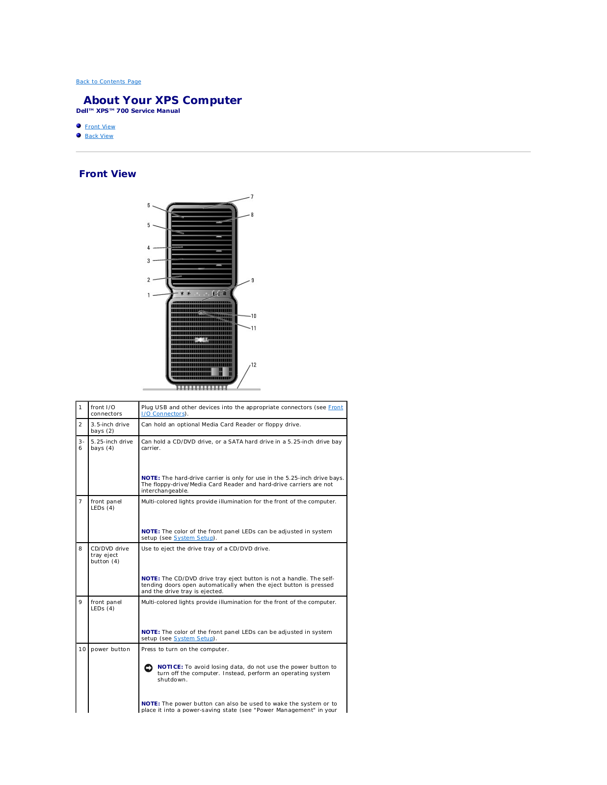
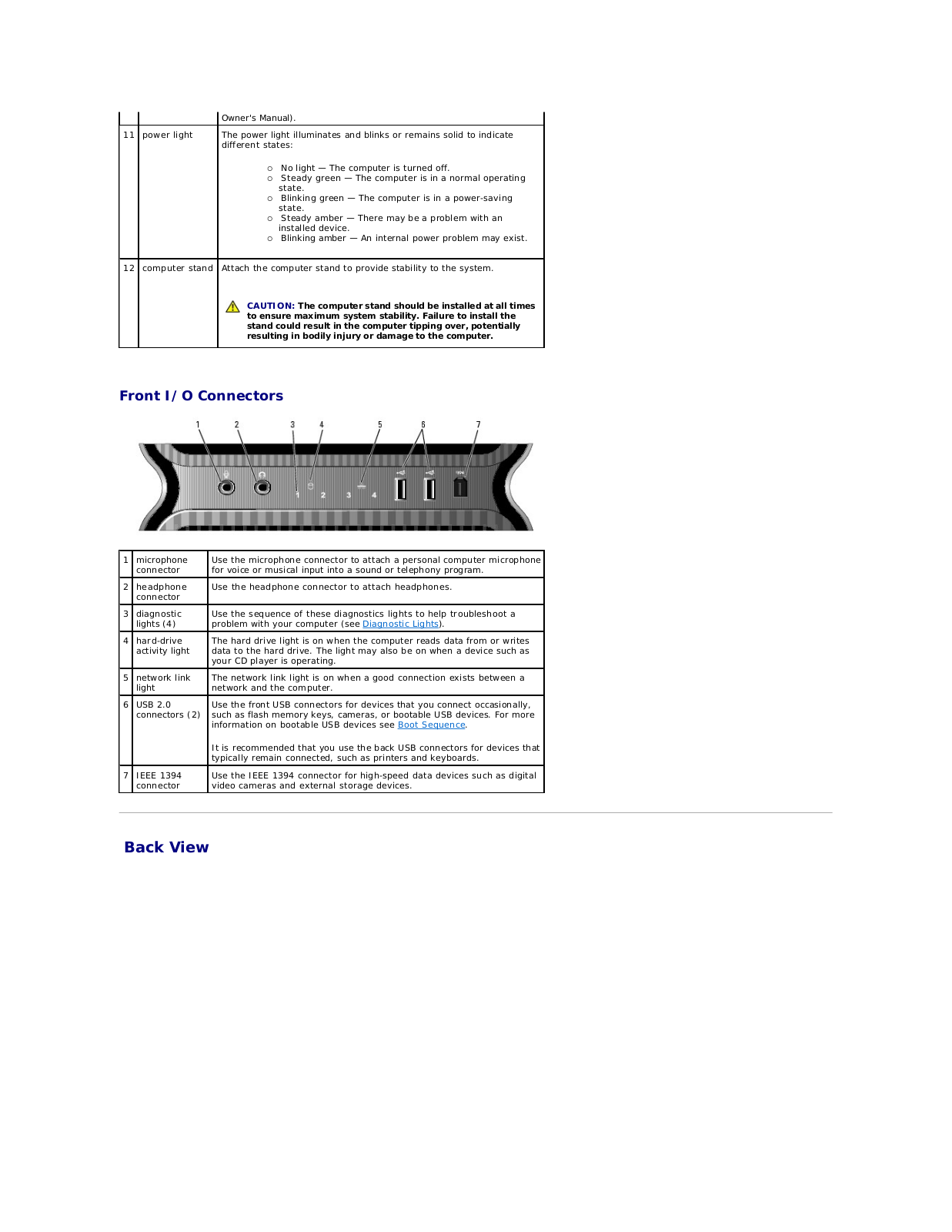
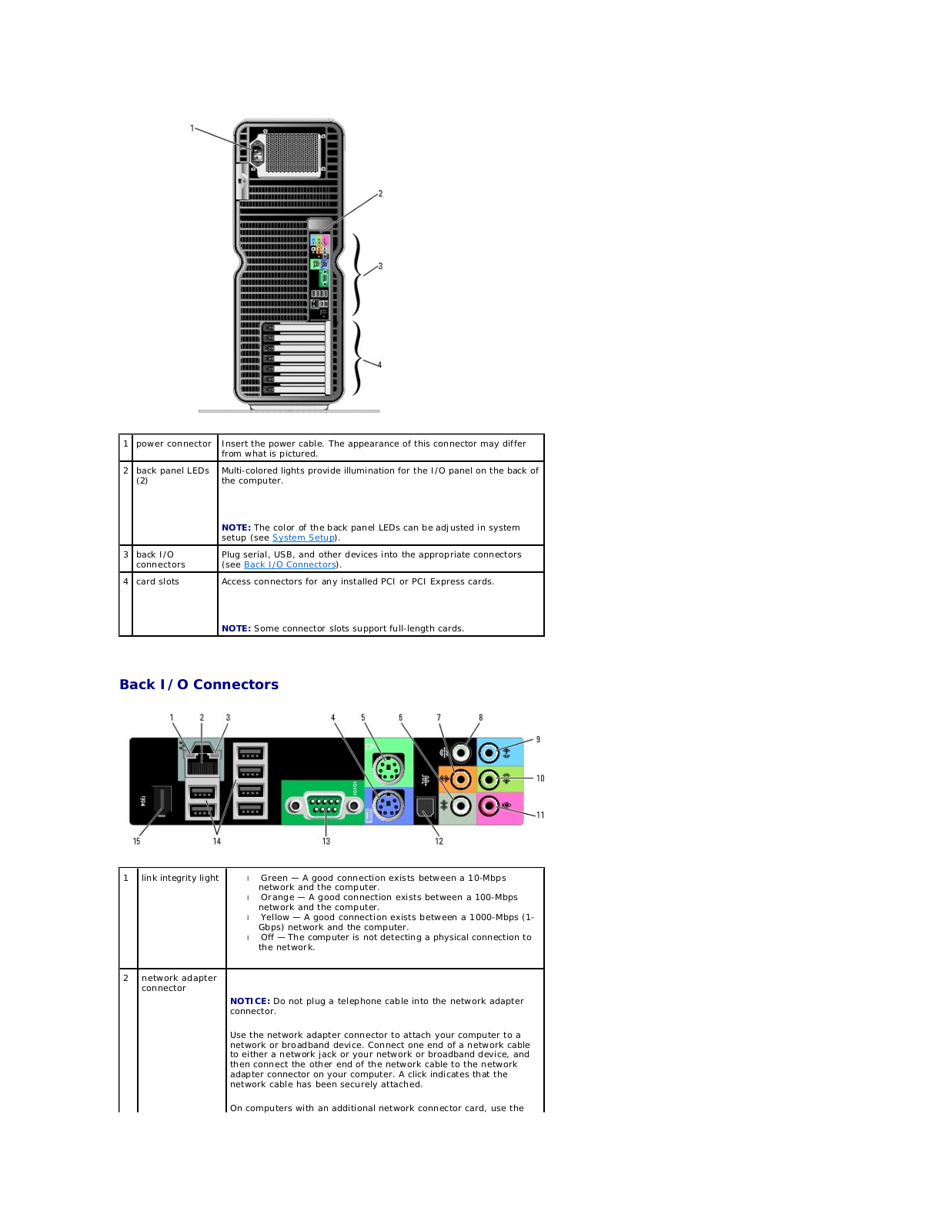
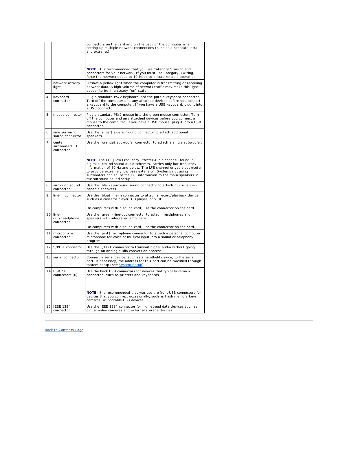
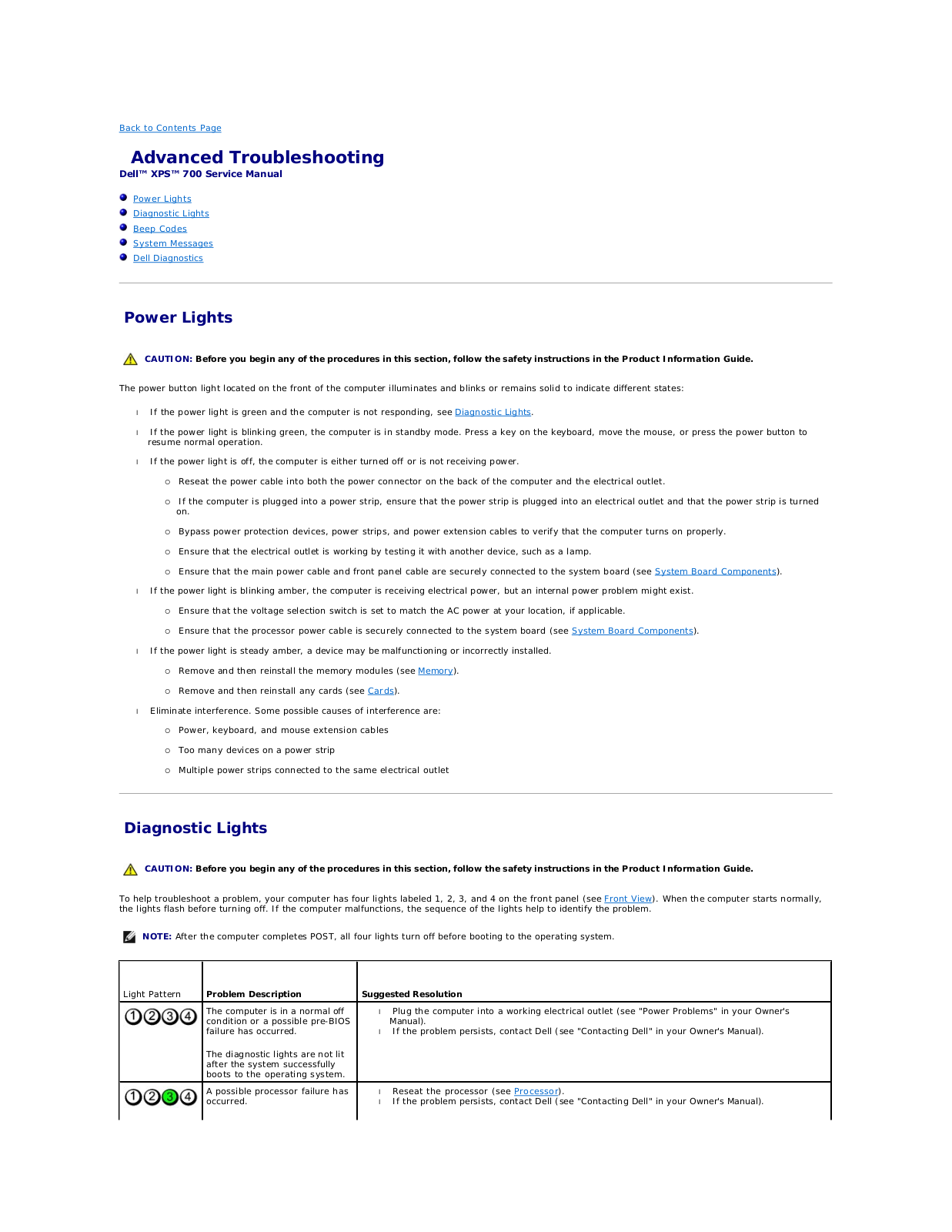
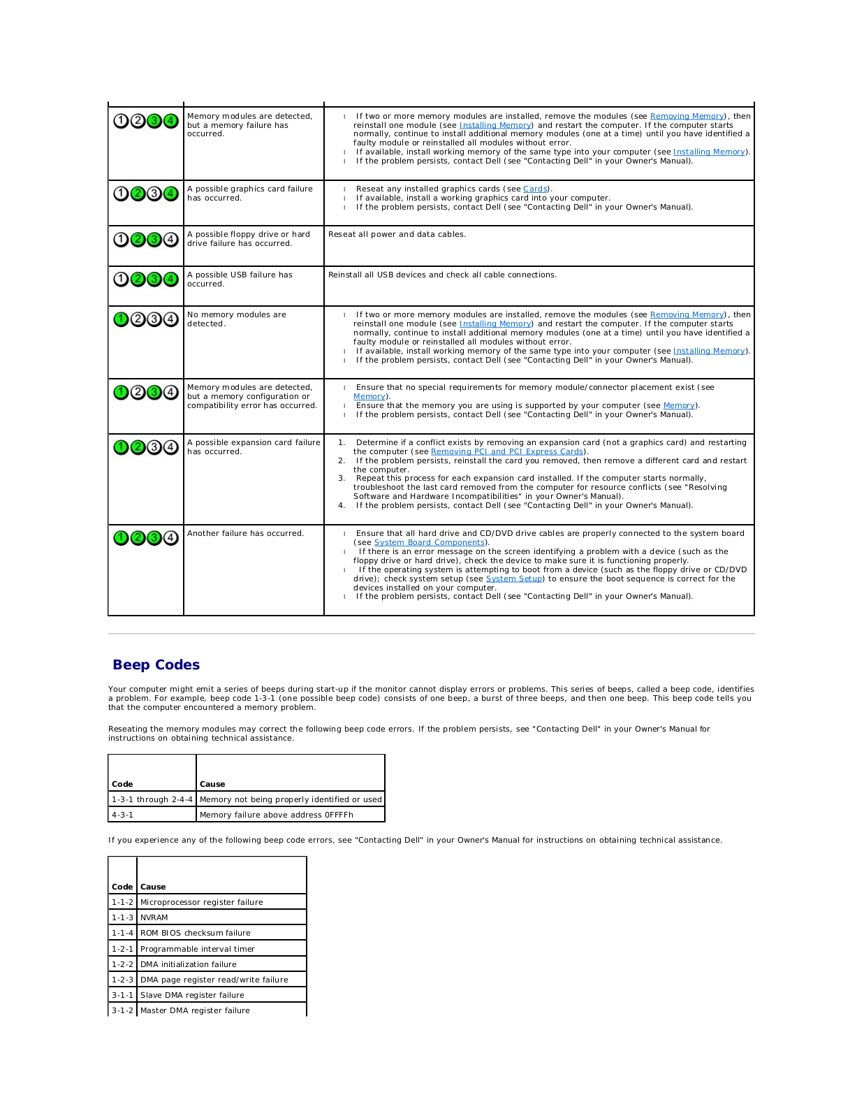
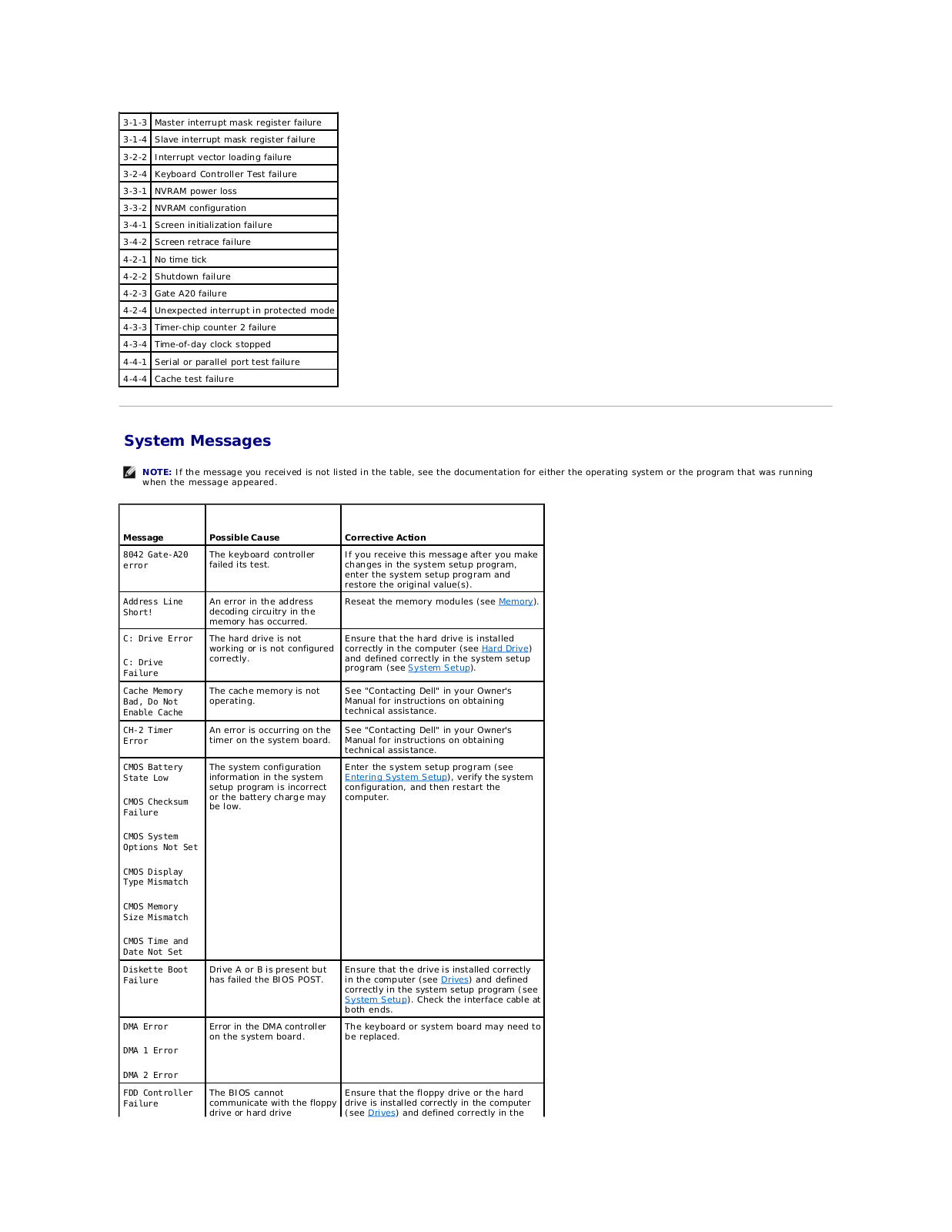
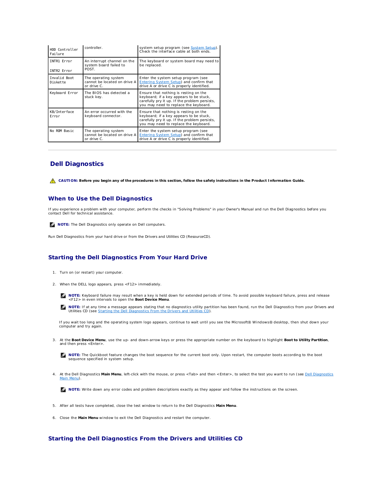
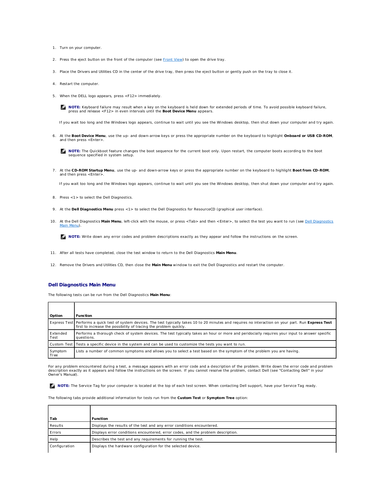
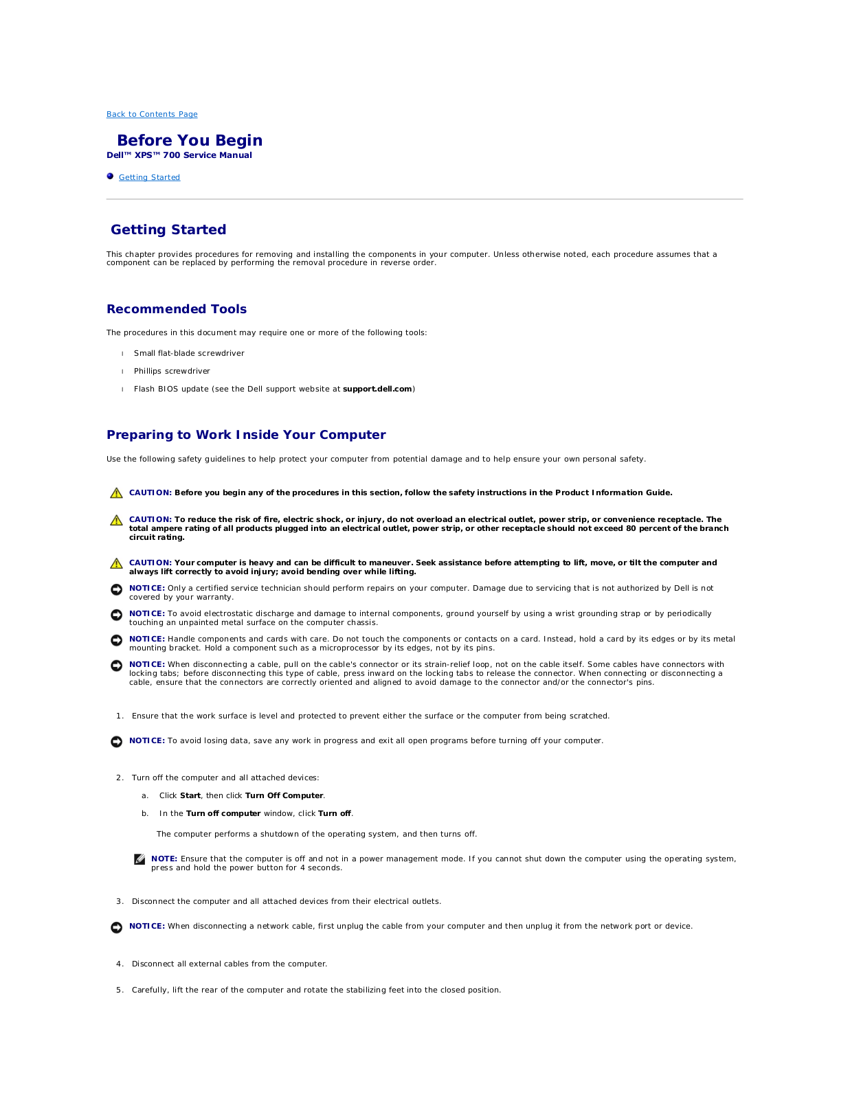
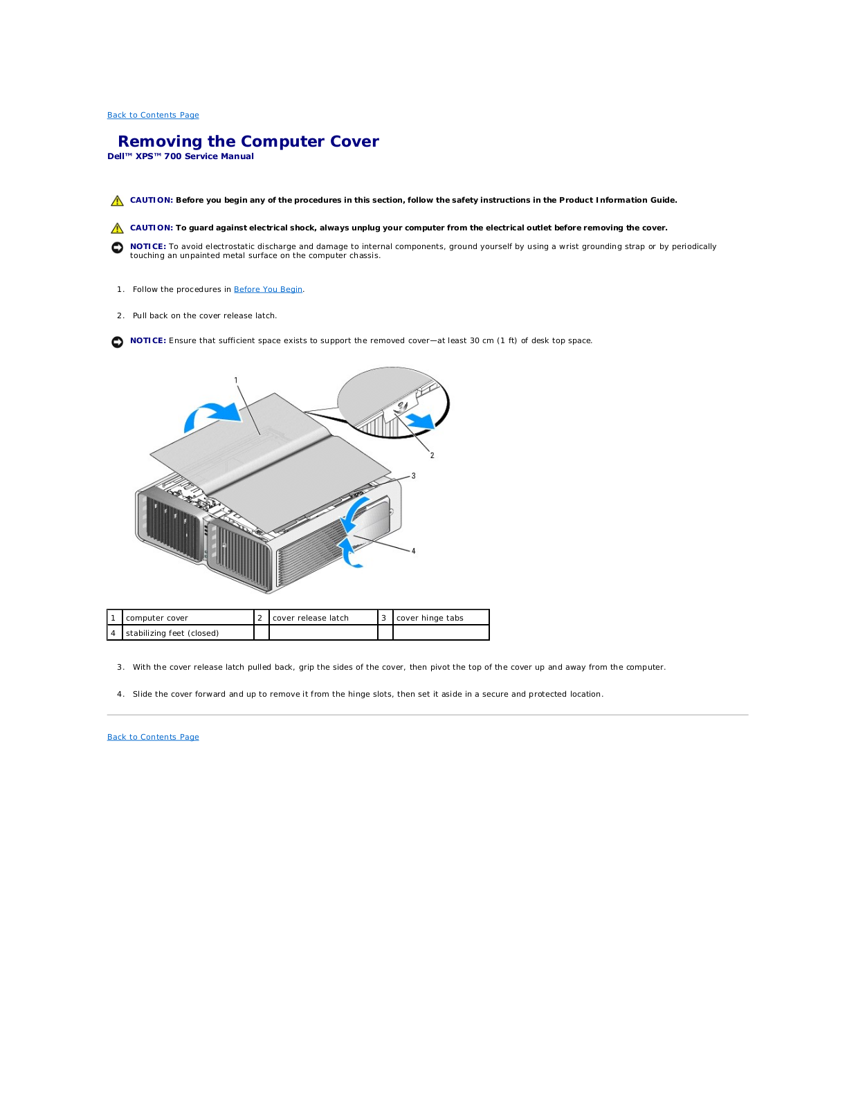
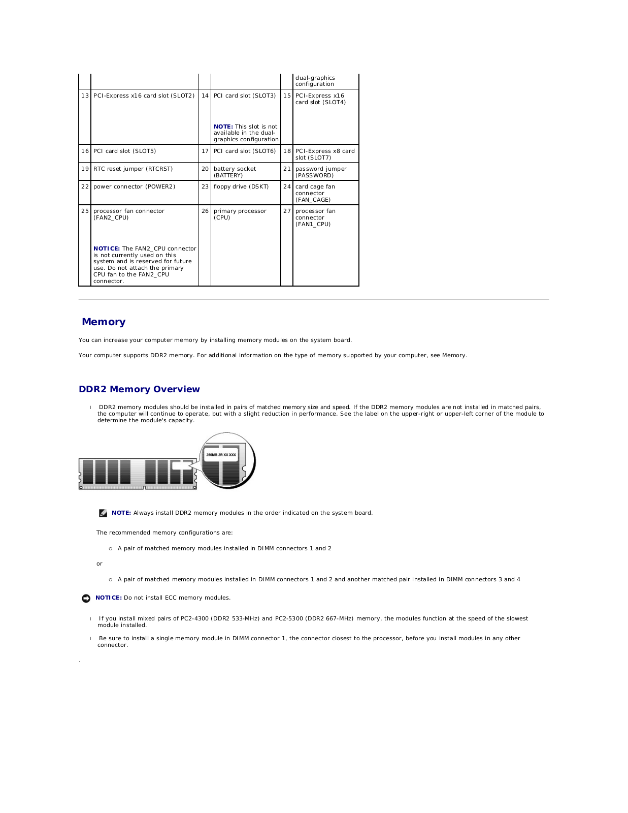
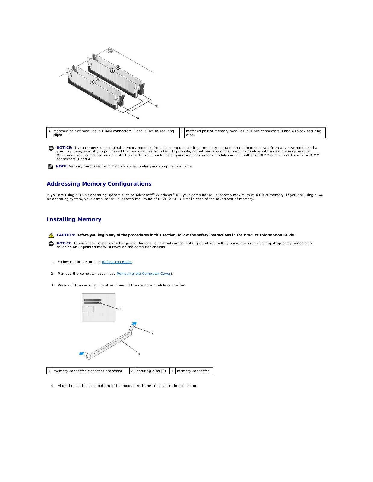
Dell XPS 710 Service Manual
...
Dell Service Manual
Download
Specifications and Main Features
Frequently Asked Questions
User Manual
Download
Loading...
+
46
hidden pages
Unhide
You need points to download manuals.
1 point = 1 manual.
You can buy points or you can get point for every manual you upload.
Buy points
Upload your manuals
 Loading...