

Page 1

Dell™ PowerEdge™ R900 Systems
Hardware Owner’s Manual
Page 2

Notes, Notices, and Cautions
NOTE: A NOTE indicates important information that helps you make better use of
your computer.
NOTICE: A NOTICE indicates either potential damage to hardware or loss of data
and tells you how to avoid the problem.
CAUTION: A CAUTION indicates a potential for property damage, personal injury,
or death.
Information in this document is subject to change without notice.
© 2007 Dell Inc. All rights reserved.
Reproduction in any manner whatsoever without the written permission of Dell Inc. is strictly
forbidden.
Trademarks used in this text: Dell and the DELL logo are trademarks of Dell Inc.; Intel and Xeon are
registered trademarks of Intel Corporation; Microsoft and Windows are registered trademarks and
Windows Server is a trademark of Microsoft Corporation; Novell and NetWare are registered
trademarks of Novell, Inc.; Red Hat is a registered trademark of Red Hat, Inc.; SUSE is a registered
trademark of SUSE LINUX Products GmbH.
Other trademarks and trade names may be used in this document to refer to either the entities claiming
the marks and names or their products. Dell Inc. disclaims any proprietary interest in trademarks and
trade names other than its own.
September 2007 P/N XK946 Rev. A00
Page 3

Contents
1 About Your System . . . . . . . . . . . . . . . . . 11
Other Information You May Need . . . . . . . . . . . . 11
Accessing System Features During Startup . . . . . . 12
Front Panel Features and Indicators
Hard Drive Indicator Codes
Connecting External Devices
Back Panel Features and Indicators
Connecting External Devices
Power Indicator Codes
. . . . . . . . . . . . . . . . . 20
. . . . . . . . . . 13
. . . . . . . . . . . . 15
. . . . . . . . . . . 18
. . . . . . . . . . 19
. . . . . . . . . . . 20
NIC Indications . . . . . . . . . . . . . . . . . . . . . 22
LCD Status Messages
. . . . . . . . . . . . . . . . . . 22
Solving Problems Described by LCD Status Messages
Removing LCD Status Messages
System Messages
Warning Messages
. . . . . . . . . . . . . . . . . . . . 34
. . . . . . . . . . . . . . . . . . . 39
. . . . . . . . . 33
Diagnostics Messages . . . . . . . . . . . . . . . . . 39
Alert Messages
. . . . . . . . . . . . . . . . . . . . . 39
2 Using the System Setup Program . . . . . . 41
33
Entering the System Setup Program . . . . . . . . . . 41
Contents 3
Page 4

Responding to Error Messages . . . . . . . . . . 41
Using the System Setup Program
. . . . . . . . . 42
System Setup Options
Main Screen
Memory Information Screen
. . . . . . . . . . . . . . . . . . 43
. . . . . . . . . . . . . . . . . . . . 43
. . . . . . . . . . . . 45
CPU Information Screen . . . . . . . . . . . . . . 45
Integrated Devices Screen
PCI IRQ Screen
. . . . . . . . . . . . . . . . . . . 47
. . . . . . . . . . . . . 46
Serial Communication Screen . . . . . . . . . . . 47
Embedded Server Management Screen
System Security Screen
. . . . . . . . . . . . . . 48
. . . . . . 48
Trusted Platform Module (TPM) Security Screen . 49
Exit Screen
System and Setup Password Features
Using the System Password
Using the Setup Password
Disabling a Forgotten Password
. . . . . . . . . . . . . . . . . . . . . 49
. . . . . . . . . 49
. . . . . . . . . . . . 50
. . . . . . . . . . . . . 53
. . . . . . . . . . . . 54
Baseboard Management Controller Configuration . . . 54
Entering the BMC Setup Module
. . . . . . . . . . 55
BMC Setup Module Options . . . . . . . . . . . . 55
3 Installing System Components . . . . . . . . 57
4 Contents
Recommended Tools . . . . . . . . . . . . . . . . . . 58
Inside the System
Removing and Installing the Top Cover
Removing the Top Cover
Installing the Top Cover
Hard Drives
. . . . . . . . . . . . . . . . . . . . 58
. . . . . . . . . 59
. . . . . . . . . . . . . . 60
. . . . . . . . . . . . . . 60
. . . . . . . . . . . . . . . . . . . . . . . 62
Page 5

Before You Begin . . . . . . . . . . . . . . . . . . 62
Removing a Drive Blank
. . . . . . . . . . . . . . 62
Installing a Drive Blank . . . . . . . . . . . . . . 63
Removing a Hot-Plug Hard Drive
Installing a Hot-Plug Hard Drive
. . . . . . . . . 64
. . . . . . . . . . 65
Replacing a Hard Drive Carrier
Removing a Hard Drive From a Hard Drive Carrier
. . . . . . . . . . . . . 66
66
Installing a SAS Hard Drive Into a SATAu Drive Carrier
Installing a SATA Hard Drive Into a SATAu Hard Drive Carrier 67
Power Supplies . . . . . . . . . . . . . . . . . . . . . 68
Removing a Power Supply
. . . . . . . . . . . . . 68
Installing a Power Supply . . . . . . . . . . . . . 69
System Fans . . . . . . . . . . . . . . . . . . . . . . . 70
Removing a Front System Fan
. . . . . . . . . . . 70
Hot-plugging a Front System Fan . . . . . . . . . 71
Removing a Back System Fan
Installing a Back System Fan
. . . . . . . . . . . 72
. . . . . . . . . . . 73
Hot-plugging a Back System Fan . . . . . . . . . 73
Removing a Back System Fan Housing
Installing a Back System Fan Housing
Cooling Shroud
. . . . . . . . . . . . . . . . . . . . . 76
Removing the Cooling Shroud
Installing the Cooling Shroud
SAS Controller Card
. . . . . . . . . . . . . . . . . . . 78
Removing a SAS Controller Card
Installing an SAS Controller Card
. . . . . . . . . . . 77
. . . . . . 74
. . . . . . . 75
. . . . . . . . . . . 76
. . . . . . . . . 80
. . . . . . . . . 80
SAS and SAS RAID Controller Card Cabling Guidelines 80
66
RAID Battery . . . . . . . . . . . . . . . . . . . . . . . 84
Installing a RAID Battery
. . . . . . . . . . . . . . 84
Contents 5
Page 6

Removing a RAID Battery . . . . . . . . . . . . . 85
Configuring the Boot Device
. . . . . . . . . . . . . . 86
PCI Express Add-in Cards . . . . . . . . . . . . . . . . 86
Installing a PCI Express Card
. . . . . . . . . . . . 86
Removing a PCI Express Card . . . . . . . . . . . 88
Optical Drive . . . . . . . . . . . . . . . . . . . . . . . 88
Removing the Optical Drive
. . . . . . . . . . . . 88
Installing the Optical Drive . . . . . . . . . . . . . 89
Replacing an Optical Drive Mounting Tray . . . . . . . 90
Removing an Optical Drive From an Optical Drive Mounting Tray
90
Installing an Optical Drive Into an Optical Drive Mounting Tray
92
System Memory
General Memory Module Installation Guidelines
Non-Optimal Memory Configurations
. . . . . . . . . . . . . . . . . . . . . 92
. 92
. . . . . . . 93
Memory Sparing Support . . . . . . . . . . . . . 93
Memory Mirroring Support
Removing a Memory Riser
. . . . . . . . . . . . . 94
. . . . . . . . . . . . . 96
Installing a Memory Riser . . . . . . . . . . . . . 98
Memory Population Rules
Removing the Memory Riser Cover
. . . . . . . . . . . . . 98
. . . . . . . . 99
Installing Memory Modules . . . . . . . . . . . . 99
Removing Memory Modules
. . . . . . . . . . . . 101
6 Contents
Processors
. . . . . . . . . . . . . . . . . . . . . . . . 101
Removing a Processor Heat Sink
Installing a Processor Heat Sink
Removing a Processor
. . . . . . . . . . . . . . . 104
. . . . . . . . . 101
. . . . . . . . . . 104
Installing a Processor . . . . . . . . . . . . . . . 105
Page 7

System Battery . . . . . . . . . . . . . . . . . . . . . . 108
Replacing the System Battery
. . . . . . . . . . . 108
Activating the NIC TOE
. . . . . . . . . . . . . . . . . 110
I/O Riser . . . . . . . . . . . . . . . . . . . . . . . . . 110
Removing the I/O Riser
. . . . . . . . . . . . . . . 110
Installing the I/O Riser . . . . . . . . . . . . . . . 111
Installing a DRAC . . . . . . . . . . . . . . . . . . . . 112
SAS Backplane (Service-only Procedure)
Removing the SAS Backplane (3.5" Hard Drives)
Installing the SAS Backplane (3.5-inch Hard Drives)
. . . . . . . 114
. 114
116
Removing the SAS Backplane (2.5-inch Hard Drives) 116
Installing the SAS Backplane (2.5" Hard Drives)
Power Interposer Board (Service-only Procedure)
Removing the Power Interposer Board
Installing the Power Interposer Board
System Board (Service-only Procedure)
Removing the System Board
Installing the System Board
. . . . . . . . . . . . 122
. . . . . . . . . . . . 124
. . . . . . . 121
. . . . . . . . 122
. . 119
. . 119
. . . . . . 119
4 Troubleshooting Your System . . . . . . . . 127
Safety First—For You and Your System . . . . . . . . . 127
Start-Up Routine . . . . . . . . . . . . . . . . . . . . . 127
Checking the Equipment
Troubleshooting IRQ Assignment Conflicts
Troubleshooting External Connections
Troubleshooting the Video Subsystem . . . . . . . 129
Troubleshooting the Keyboard
. . . . . . . . . . . . . . . . 128
. . . . 128
. . . . . . 129
. . . . . . . . . . . 130
Contents 7
Page 8

Troubleshooting the Mouse . . . . . . . . . . . . 131
Troubleshooting Basic I/O Functions
Troubleshooting a Serial I/O Device
Troubleshooting a USB Device
Troubleshooting a NIC
. . . . . . . . . . . . . . . . . . 133
. . . . . . . . . . 131
. . . . . . . . 132
. . . . . . . . . . . 132
Troubleshooting a Wet System . . . . . . . . . . . . . 134
Troubleshooting a Damaged System
Troubleshooting the System Battery
. . . . . . . . . . 135
. . . . . . . . . . 136
Troubleshooting Power Supplies . . . . . . . . . . . . 137
Troubleshooting System Cooling
Troubleshooting a Fan
Troubleshooting System Memory
. . . . . . . . . . . . 138
. . . . . . . . . . . . . . . 138
. . . . . . . . . . . . 139
Troubleshooting an Optical Drive . . . . . . . . . . . . 141
Troubleshooting a Hard Drive
Troubleshooting a SAS or SAS RAID Controller Card
. . . . . . . . . . . . . . 142
. 144
Troubleshooting Expansion Cards . . . . . . . . . . . 145
5 Running the System Diagnostics . . . . . . 149
8 Contents
Troubleshooting Processors
. . . . . . . . . . . . . . 147
Using PowerEdge Diagnostics . . . . . . . . . . . . . 149
System Diagnostics Features . . . . . . . . . . . . . . 149
When to Use the System Diagnostics
Executing System Diagnostics
. . . . . . . . . . 150
. . . . . . . . . . . . . 150
Page 9

System Diagnostics Testing Options . . . . . . . . . . 150
Using the Custom Test Options
Selecting Devices for Testing
Selecting Diagnostics Options
Viewing Information and Results
. . . . . . . . . . . . . 151
. . . . . . . . . . . 151
. . . . . . . . . . . 151
. . . . . . . . . 152
6 Jumpers and Connectors . . . . . . . . . . . 153
System Board Jumpers and Connectors . . . . . . . . 153
System Board Connectors
. . . . . . . . . . . . . . . . 154
SAS Backplane Connectors . . . . . . . . . . . . . . . 156
Power Interposer Connectors
Disabling a Forgotten Password
. . . . . . . . . . . . . . 160
. . . . . . . . . . . . 162
7 Getting Help . . . . . . . . . . . . . . . . . . . . . 165
Obtaining Assistance . . . . . . . . . . . . . . . . . . 165
Online Services
Automated Order-Status Service . . . . . . . . . 167
Support Service
. . . . . . . . . . . . . . . . . . 166
. . . . . . . . . . . . . . . . . . 167
Dell Enterprise Training and Certification
. . . . . . . 167
Problems With Your Order . . . . . . . . . . . . . . . 167
Product Information
Returning Items for Warranty Repair or Credit
. . . . . . . . . . . . . . . . . . . 167
. . . . . 167
Before You Call . . . . . . . . . . . . . . . . . . . . . 168
Contacting Dell
. . . . . . . . . . . . . . . . . . . . . 170
Contents 9
Page 10

Glossary . . . . . . . . . . . . . . . . . . . . . . . . . 171
10 Contents
Page 11

1
About Your System
This section describes the physical, firmware, and software interface features
that provide and ensure the essential functioning of your system. The
physical connectors on your system’s front and back panels provide
convenient connectivity and system expansion capability. The system
firmware, applications, and operating systems monitor the system and
component status and alert you when a problem arises. System conditions
can be reported by any of the following:
• Front or back panel indicators
• System messages
• Warning messages
• Diagnostics messages
•Alert messages
This section describes each type of message, lists the possible causes, and
provides steps to resolve any problems indicated by a message. The system
indicators and features are illustrated in this section.
Other Information You May Need
CAUTION: The Product Information Guide provides important safety and
regulatory information. Warranty information may be included within this
document or as a separate document.
•The
•The
• CDs included with your system provide documentation and tools for
Rack Installation Guide or Rack Installation Instructions
with your rack solution describes how to install your system into a rack.
Getting Started Guide
setting up your system, and technical specifications.
configuring and managing your system.
provides an overview of system features,
About Your System 11
included
Page 12

• Systems management software documentation describes the features,
requirements, installation, and basic operation of the software.
• Operating system documentation describes how to install (if necessary),
configure, and use the operating system software.
• Documentation for any components you purchased separately provides
information to configure and install these options.
• Updates are sometimes included with the system to describe changes to
the system, software, and/or documentation.
NOTE: Always check for updates on support.dell.com and read the updates first
because they often supersede information in other documents.
• Release notes or readme files may be included to provide last-minute
updates to the system or documentation or advanced technical reference
material intended for experienced users or technicians.
Accessing System Features During Startup
Table 1-1 describes keystrokes that may be entered during startup to access
system features. If your operating system begins to load before you enter the
keystroke, allow the system to finish booting, and then restart your system
and try again.
Table 1-1. Keystrokes for Accessing System Functions
Keystroke Description
<F2> Enters the System Setup program. See "Using the System Setup
Program" on page 41.
<F10> Opens the utility partition, allowing you to run the system
diagnostics. See
<F11> Enters the boot menu.
<F12> Enters the PXE boot.
<Ctrl><c> Enters the SAS Configuration Utility. See your
for more information.
Guide
<Ctrl><e> Enters the Baseboard Management Controller (BMC) Management
Utility, which allows access to the system event log (SEL). See the
BMC User’s Guide
"Running the System Diagnostics
for more information on setup and use of BMC.
" on page 149
SAS adapter User’s
.
12 About Your System
Page 13
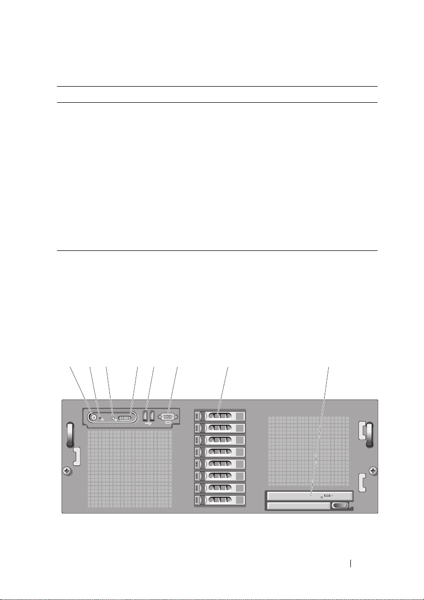
Table 1-1. Keystrokes for Accessing System Functions
123 45 6 87
Keystroke Description
<Ctrl><r> Enters the RAID configuration utility, which allows you to configure
an optional RAID card. For more information, see the documentation
for your RAID card.
<Ctrl><s> Option is displayed only if you have PXE support enabled through the
System Setup Program (see "Using the System Setup Program" on
page 41). This keystroke allows you to configure NIC settings for PXE
boot. For more information, see the documentation for your
integrated NIC.
<Ctrl><d> If you have the optional Dell Remote Assistant Card (DRAC), this
keystroke allows access to selected DRAC configuration settings. See
DRAC User’s Guide
the
DRAC.
for more information on setup and use of
Front Panel Features and Indicators
Figure 1-1 shows the controls, indicators, connectors, and drives on the
system's front panel.
Figure 1-1. Front Panel Features and Indicators
About Your System 13
Page 14

1 Power button/indicator. The power-on indicator lights when the
system power is on.
The power button controls the DC
power supply output to the system.
NOTE: If you turn off the system using the
power button and the system is running an
ACPI-compliant operating system, the
system performs a graceful shutdown
before the power is turned off. If the
system is not running an ACPI-compliant
operating system, the power is turned off
immediately after the power button is
pressed.
2 NMI button. Used to troubleshoot software and
device driver errors when using certain
operating systems. This button can be
pressed using the end of a paper clip.
Use this button only if directed to do so
by qualified support personnel or by the
operating system's documentation.
3 System identification button. The identification buttons on the front
and back panels can be used to locate a
particular system within a rack. When
one of these buttons is pushed, the LCD
panel on the front and the blue system
status indicator on the back blink until
one of the buttons is pushed again.
14 About Your System
Page 15

4 LCD panel. Provides system ID, status information,
and system error messages.
The LCD lights during normal system
operation. Both the systems
management software and the
identification buttons located on the
front and back of the system can cause
the LCD to flash blue to identify a
particular system.
The LCD lights amber when the system
needs attention, and the LCD panel
displays an error code followed by
descriptive text.
If the system is connected to AC power
and an error has been detected, the LCD
lights amber regardless of whether the
system has been powered on.
5 USB connectors (2). Connects USB 2.0-compliant devices to
the system.
6 Video connector. Connects a monitor to the system.
7 Hard drives. Eight 2.5-inch hot-plug or five 3.5-inch
hot-plug.
8 Optical drive. One slimline optical drive.
Hard Drive Indicator Codes
The hard drive carriers have two indicators—the drive-activity indicator and
the drive-status indicator.
About Your System 15
Page 16
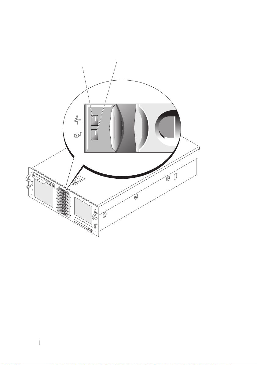
Figure 1-2. Hard Drive Indicators
1
2
1 green and amber drive-status
indicator
2 green drive-activity indicator
The Activity LED indicates command activity between the hard disk drives
and storage controller.
The Status LED is a bi-color (Green/Amber) LED that indicates the state of a
drive in a slot. The color and blink rate of the LED indicates the state of the
drive as shown in Table 1-2.
16 About Your System
Page 17

Table 1-2. Hard Drive Indicators
Pattern Green element Amber eLement Drive/slot state
Slot empty Off Off The slot is empty, an
unsupported drive is
present, the drive has
been spun down for
removal (Ready for
Removal), or a new
drive has been inserted,
and the state has not
been updated by the
RAID controller.
Drive online On Off The drive is either
online, ready, a hotspare
or a foreign drive.
Drive identify
(prep for removal)
Drive rebuilding On ~400mS
Drive failed Off On ~150mS
Predicted Failure
(SMART)
On ~250mS
Off ~250mS
Off ~100mS
On ~500mS
Off ~500mS
Off ~1000S
Off The slot is being
identified because of a
user request (either a
drive identify or a
preparing for removal
was requested).
Off The drive is being
written to, to make a
virtual disk redundant.
The RAID controller
Off ~150mS
Off ~500mS
On ~500mS
can no longer access or
control (read/write to)
the drive because it has
detected an
unrecoverable fault
(after it has completed
its error handling) on
the drive.
Predictive failure event
has been reported by
the drive.
About Your System 17
Page 18

Table 1-2. Hard Drive Indicators
Pattern Green element Amber eLement Drive/slot state
Rebuild Abort On ~3000mS
Off ~9000mS
Off ~6000mS
On ~3000mS
Off ~3000mS
The drive has been
spun down by a user
request (Prepare to
Remove operation), or
had a rebuild operation
on it aborted by a user
action or due to any
reason other than a
drive failure.
In RAID configurations, the drive-status indicator lights to indicate the status
of the drive.
NOTE: For non-RAID configurations, only the drive-activity indicator is active. The
drive-status indicator is off.
Table 1-2 lists the drive indicator patterns for RAID hard drives. Different
patterns are displayed as drive events occur in the system. For example, if a
hard drive fails, the "drive failed" pattern appears. After the drive is selected
for removal, the "drive being prepared for removal" pattern appears, followed
by the "drive ready for insertion or removal" pattern. After the replacement
drive is installed, the "drive being prepared for operation" pattern appears,
followed by the "drive online" pattern.
Connecting External Devices
When connecting external devices to your system, follow these guidelines:
• Most devices must be connected to a specific connector and device drives
must be installed before the device operates properly. (Device drivers are
normally included with your operating system software or with the device
itself.) See the documentation that accompanied the device for specific
installation and configuration instructions.
• Always attach external devices while your system and the device are turned
off. Next, turn on any external devices before turning on the system
(unless the documentation for the device specifies otherwise).
18 About Your System
Page 19
For information about individual connectors, see "Jumpers and Connectors"
1234 78
12 11 10 9
56
on page 153. For information about enabling, disabling, and configuring I/O
ports and connectors, see "Using the System Setup Program" on page 41.
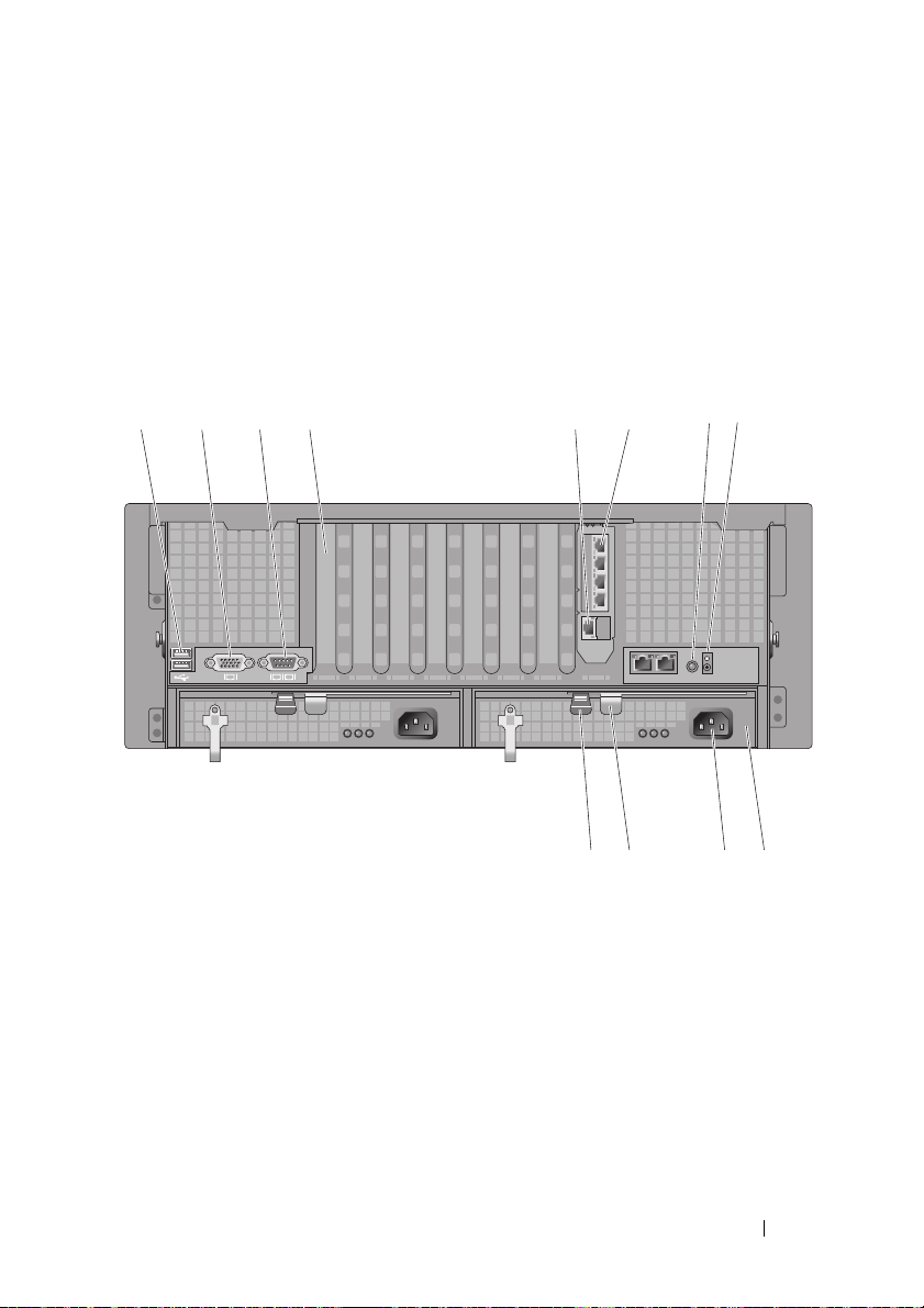
Back Panel Features and Indicators
Figure 1-3 shows the controls, indicators, and connectors located on the
system's back panel.
Figure 1-3. Back Panel Features and Indicators
1 USB connectors (2) 2 Video connector
3 Serial connector 4 Expansion card filler bracket
5 DRAC network connector 6 Network connectors (4)
7 System identification button 8 Intrusion LED
9 Power supply 10 Power connector
11 Power supply lever 12 Power supply latch
About Your System 19
Page 20

Connecting External Devices
When connecting external devices to your system, follow these guidelines:
• Most devices must be connected to a specific connector and device drivers
must be installed before the device operates properly. (Device drivers are
normally included with your operating system software or with the device
itself.) See the documentation that accompanied the device for specific
installation and configuration instructions.
• Always attach external devices while your system and the device are turned
off. Next, turn on any external devices before turning on the system
(unless the documentation for the device specifies otherwise).
For information about individual connectors, see "Jumpers and Connectors"
on page 153. For information about enabling, disabling, and configuring I/O
ports and connectors, see "Using the System Setup Program" on page 41.
Power Indicator Codes
The power button on the front panel controls the power input to the system's
power supplies. The power indicator lights green when the system is on.
The indicators on the redundant power supplies show whether power is
present or whether a power fault has occurred (see Figure 1-4). Table 1-3 lists
the power supply indicator codes.
20 About Your System
Page 21
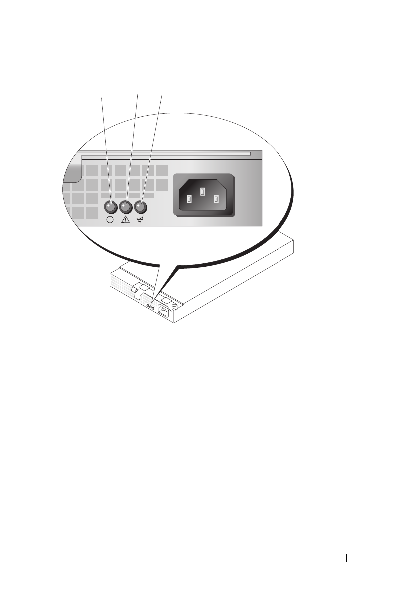
Figure 1-4. Redundant Power Supply Indicators
1
2
3
1 power supply status 2 power supply fault
3 AC line status
Table 1-3. Redundant Power Supply Indicators
Indicator Function
Power supply status Green indicates that the power supply is
operational.
Power supply fault Amber indicates a problem with the power supply.
AC line status Green indicates that a valid AC source is connected
to the power supply.
About Your System 21
Page 22
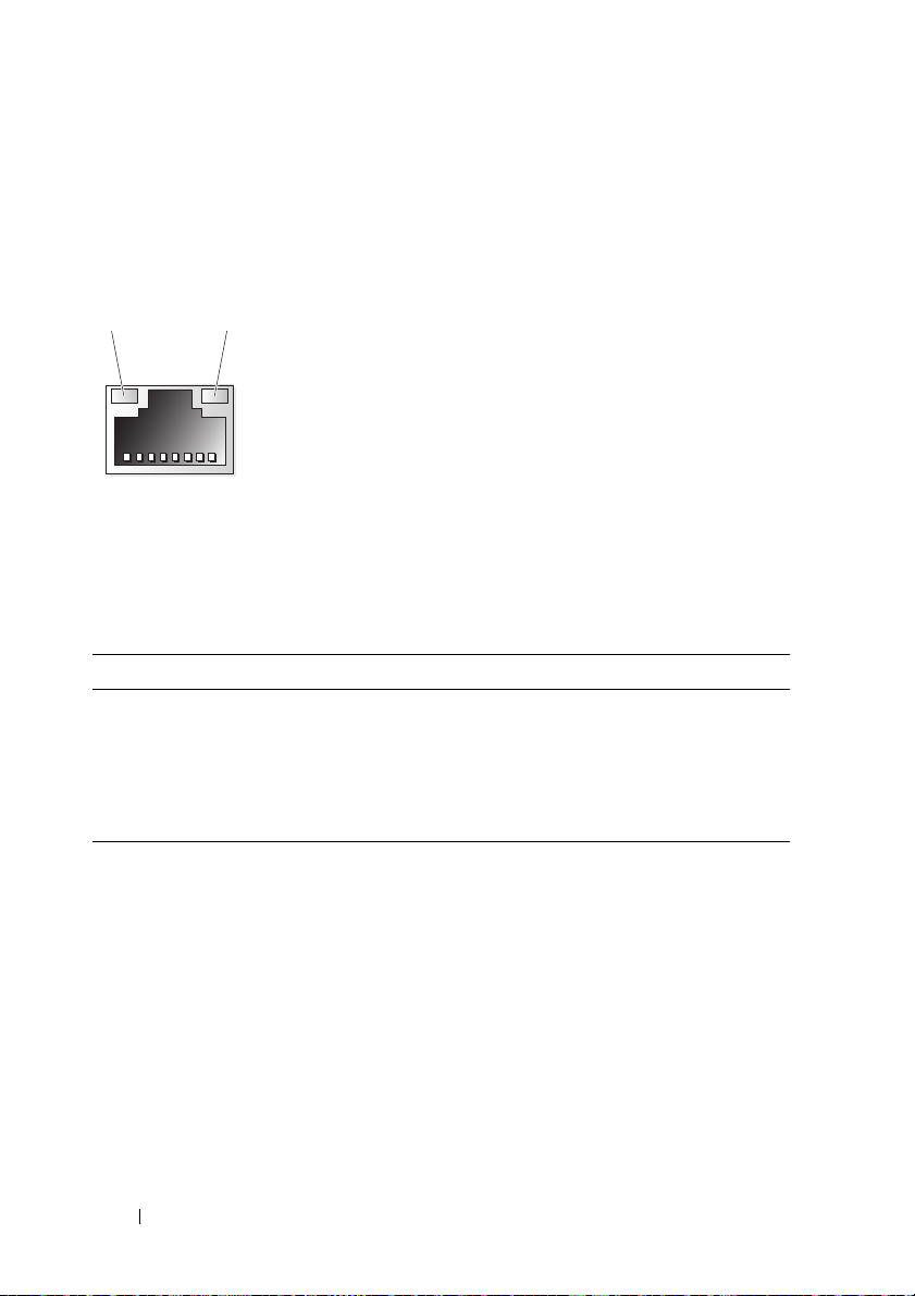
NIC Indications
Each NIC has two indicators that provides information on network activity
and link status. See Figure 1-5. Table 1-4 lists the NIC indications.
Figure 1-5. NIC Indicators
1 2
1 link indicator (green) 2 activity indicator (amber)
Table 1-4. NIC Indications
Indicators Illumination Meaning
Link and activity indicators are
off.
Link indicator is on. The NIC is connected to a valid link partner on the
Activity indicator is blinking. Network data is being transmitted.
The NIC is not connected to the network.
network.
LCD Status Messages
The system's control panel LCD provides status messages to signify when the
system is operating correctly or when the system needs attention.
The LCD lights blue to indicate a normal operating condition, and lights
amber to indicate an error condition. The LCD scrolls a message that
includes a status code followed by descriptive text. Table 1-5 lists the LCD
status messages that can occur and the probable cause for each message. The
LCD messages refer to events recorded in the System Event Log (SEL). For
information on the SEL and configuring system management settings, see
the systems management software documentation.
22 About Your System
Page 23
CAUTION: Only trained service technicians are authorized to remove the system
cover and access any of the components inside the system. See your Product
Information Guide for complete information about safety precautions, working
inside the computer, and protecting against electrostatic discharge.
NOTE: If your system fails to boot, press the System ID button for at least five
seconds until an error code appears on the LCD. Record the code, then see "Getting
Help" on page 165.
Table 1-5. LCD Status Messages
Code Test Causes Corrective Actions
N/A
E1000 FAILSAFE,
SYSTEM NAME
CALL
A 62-character string that
can be defined by the user
in the System Setup
program.
SYSTEM NAME
The
displays under the
following conditions:
• The system is powered
on.
• The power is off and
active POST errors are
displayed.
This message is for
information only.
You can change the system
ID and name in the
System Setup program.
See "Using the System
Setup Program" on
page 41.
See "Getting Help" on
page 165.
SUPPORT
E1114 Temp
Ambient
E1116 Temp Memory
E12nn xx PwrGd
Ambient system
temperature is out of
acceptable range.
Memory has exceeded
acceptable temperature
and has been disabled to
prevent damage to the
components.
Specified voltage regulator
has failed.
See "Troubleshooting
System Cooling" on
page 138.
See "Troubleshooting
System Cooling" on
page 138.
See "Getting Help" on
page 165.
About Your System 23
Page 24

Table 1-5. LCD Status Messages
Code Test Causes Corrective Actions
E1210 CMOS Batt
E1211 ROMB Batt
E1229 CPU # VCORE
E1310 RPM Fan ##
E1313 Fan
Redundancy
E1410 CPU # IERR
CMOS battery is missing,
or the voltage is out of
acceptable range.
RAID battery is either
missing, bad, or unable to
recharge due to thermal
issues.
Processor # VCORE
voltage regulator has failed.
RPM of specified cooling
fan is out of acceptable
operating range.
The system is no longer
fan-redundant. Another
fan failure will put the
system at risk of
overheating.
Specified microprocessor is
reporting an internal error.
See "Troubleshooting the
System Battery" on
page 136.
Reseat the RAID battery
connector. See "Installing a
RAID Battery" on page 84,
and "Troubleshooting the
System Battery" on
page 136.
See "Getting Help" on
page 165.
See "Troubleshooting
System Cooling" on
page 138.
Check control panel LCD
for additional scrolling
messages. See
"Troubleshooting System
Cooling" on page 138.
See your system’s
Information Update Tech
Sheet located on
support.dell.com for the
most current system
information. If problem
persists, see "Getting Help"
on page 165.
24 About Your System
Page 25

Table 1-5. LCD Status Messages
Code Test Causes Corrective Actions
E1414 CPU #
Thermtrip
Specified microprocessor is
out of acceptable
temperature range and has
halted operation.
See "Troubleshooting
System Cooling" on
page 138. If the problem
persists, ensure that the
processor heat sinks are
properly installed. See
"Troubleshooting
Processors" on page 147.
NOTE: The LCD continues
to display this message until
the system’s power cord is
disconnected and
reconnected to the AC
power source, or the SEL is
cleared using either Server
Assistant or the BMC
Management Utility. See the
Dell OpenManage
Baseboard Management
Controller User’s Guide for
information about these
utilities.
E1418 CPU #
Presence
E141C CPU
Mismatch
Specified processor is
missing or bad, and the
system is in an
unsupported
configuration.
Processors are in a
configuration unsupported
by Dell.
See "Troubleshooting
Processors" on page 147.
Ensure that your
processors match and
conform to the type
described in the
Microprocessor Technical
Specifications outlined in
your system’s
Started Guide
Getting
.
About Your System 25
Page 26

Table 1-5. LCD Status Messages
Code Test Causes Corrective Actions
E141F CPU
Protocol
E1420 CPU Bus
PERR
E1421 CPU Init
E1422 CPU Machine
Chk
E1610 PS #
Missing
E1614 PS # Status
E1618 PS #
Predictive
E161C PS # Input
Lost
The system BIOS has
reported a processor
protocol error.
The system BIOS has
reported a processor
protocol error.
The system BIOS has
reported a processor
initialization error.
The system BIOS has
reported a machine check
error.
No power is available from
the specified power supply;
specified power supply is
improperly installed or
faulty.
No power is available from
the specified power supply;
specified power supply is
improperly installed or
faulty.
Power supply voltage is out
of acceptable range;
specified power supply is
improperly installed or
faulty.
Power source for specified
power supply is
unavailable, or out of
acceptable range.
See "Getting Help" on
page 165.
See "Getting Help" on
page 165.
See "Getting Help" on
page 165.
See "Getting Help" on
page 165.
See "Troubleshooting
Power Supplies" on
page 137.
See "Troubleshooting
Power Supplies" on
page 137.
See "Troubleshooting
Power Supplies" on
page 137.
Check the AC power
source for the specified
power supply. If problem
persists, see
"Troubleshooting Power
Supplies" on page 137.
26 About Your System
Page 27

Table 1-5. LCD Status Messages
Code Test Causes Corrective Actions
E1620 PS # Input
Range
E1624 PS
Redundancy
E1710 I/O Channel
Chk
E1711 PCI PERR
B## D## F##
PCI PERR
Slot #
PCI PERR
Slot #
Power source for specified
power supply is
unavailable, or out of
acceptable range.
The power supply
subsystem is no longer
redundant. If the last
supply fails, the system will
go down.
The system BIOS has
reported an I/O channel
check.
The system BIOS has
reported a PCI parity error
on a component that
resides in PCI
configuration space at bus
##, device ##, function
##.
The system BIOS has
reported a PCI parity error
on a component that
resides in the specified PCI
slot.
The system BIOS has
reported a PCI parity error
on a component that
resides in the specified PCI
slot.
Check the AC power
source for the specified
power supply. If problem
persists, see
"Troubleshooting Power
Supplies" on page 137.
See "Troubleshooting
Power Supplies" on
page 137.
See "Getting Help" on
page 165.
Remove and reseat the PCI
expansion cards. If the
problem persists, see
"Troubleshooting
Expansion Cards" on
page 145.
If the problem persists, the
riser card or system board
is faulty. See "Getting
Help" on page 165.
Remove and reseat the PCI
expansion cards. If the
problem persists, see
"Troubleshooting
Expansion Cards" on
page 145.
If the problem persists, the
riser card or system board
is faulty. See "Getting
Help" on page 165.
About Your System 27
Page 28

Table 1-5. LCD Status Messages
Code Test Causes Corrective Actions
E1712 PCI SERR
B## D## F##
PCI SERR
Slot #
E1714 Unknown Err
E171F PCIE Fatal
Err B## D##
F##
PCIE Fatal
Err Slot #
E1810 HDD ##
Fault
The system BIOS has
reported a PCI system
error on a component that
resides in PCI
configuration space at bus
##, device ##, function
##.
The system BIOS has
reported a PCI system
error on a component that
resides in the specified
slot.
The system BIOS has
determined that there has
been an error in the
system, but is unable to
determine its origin.
The system BIOS has
reported a PCIe fatal error
on a component that
resides in PCI
configuration space at bus
##, device ##, function
##.
The system BIOS has
reported a PCIe fatal error
on a component that
resides in the specified
slot.
The SAS subsystem has
determined that hard drive
## has experienced a
fault.
Remove and reseat the PCI
expansion cards. If the
problem persists, see
"Troubleshooting
Expansion Cards" on
page 145.
If the problem persists, the
riser card or system board
is faulty. See "Getting
Help" on page 165.
See "Getting Help" on
page 165.
Remove and reseat the PCI
expansion cards. If the
problem persists, see
"Troubleshooting
Expansion Cards" on
page 145.
If the problem persists, the
riser card or system board
is faulty. See "Getting
Help" on page 165.
See "Troubleshooting a
Hard Drive" on page 142.
28 About Your System
Page 29

Table 1-5. LCD Status Messages
Code Test Causes Corrective Actions
E1811 HDD ## Rbld
Abrt
E1812 HDD ##
Removed
E1913 CPU &
Firmware
Mismatch
E1A14 SAS Cable A
E1A15 SAS Cable B
E2010 No Memory
E2011 Mem Config
Error
E2012 Unusable
Memory
E2013 Shadow BIOS
Fail
The specified hard drive
has experienced a rebuild
abort.
The specified hard drive
has been removed from the
system.
The BMC firmware does
not support the processor.
SAS cable A is missing or
bad.
SAS cable B is missing or
bad.
No memory is installed in
the system.
Memory detected, but is
not configurable. Error
detected during memory
configuration.
Memory is configured, but
not usable. Memory
subsystem failure.
The system BIOS failed to
copy its flash image into
memory.
See "Troubleshooting a
Hard Drive" on page 142. If
the problem persists, see
your RAID
documentation.
Information only.
Update to the latest BMC
firmware. See the
User’s Guide
information on setup and
use of BMC.
Reseat the cable. If
problem persists, replace
cable. See "SAS Controller
Card" on page 78.
Reseat the cable. If
problem persists, replace
cable. See "SAS Controller
Card" on page 78.
Install memory. See
"General Memory Module
Installation Guidelines" on
page 92.
See "Troubleshooting
System Memory" on
page 139.
See "Troubleshooting
System Memory" on
page 139.
See "Troubleshooting
System Memory" on
page 139.
for more
BMC
About Your System 29
Page 30

Table 1-5. LCD Status Messages
Code Test Causes Corrective Actions
E2014 CMOS Fail
E2015 DMA
Controller
E2016 Int
Controller
E2017 Timer Fail
E2018 Prog Timer
E2019 Parity
Error
E201A SIO Err
E201B Kybd
Controller
E201C SMI Init
E201D Shutdown
Test
E201E POST Mem
Test
CMOS failure. CMOS
RAM not functioning
properly.
DMA controller failure. See "Getting Help" on
Interrupt controller failure. See "Getting Help" on
Timer refresh failure. See "Getting Help" on
Programmable interval
timer error.
Parity error. See "Getting Help" on
SIO failure. See "Getting Help" on
Keyboard controller failure. See "Getting Help" on
System management
interrupt (SMI)
initialization failure.
BIOS shutdown test
failure.
BIOS POST memory test
failure.
See "Getting Help" on
page 165.
page 165.
page 165.
page 165.
See "Getting Help" on
page 165.
page 165.
page 165.
page 165.
See "Getting Help" on
page 165.
See "Getting Help" on
page 165.
See "Troubleshooting
System Memory" on
page 139. If problem
persists, see "Getting Help"
on page 165.
30 About Your System
Page 31

Table 1-5. LCD Status Messages
Code Test Causes Corrective Actions
E201F DRAC Config
E2020 CPU Config
E2021 Memory
Population
E2022 POST Fail
E2110 MBE Crd #
DIMM ## &
##
E2111 SBE Log
Disable Crd
# DIMM ##
Dell Remote Assistant
Card (DRAC)
configuration failure.
processor configuration
failure.
Incorrect memory
configuration. Memory
population order incorrect.
General failure after video. Check screen for specific
One of the DIMMs in the
set implicated by "## &
##" has had a memory
multi-bit error (MBE). If
no memory card is present,
the "Crd #" string is left
out of the message.
The system BIOS has
disabled memory single-bit
error (SBE) logging, and
will not resume logging
further SBEs until the
system is rebooted. "##"
represents the DIMM
implicated by the BIOS. If
no memory riser card is
present, the "Crd #" string
is left out of the message.
Check screen for specific
error messages.
Ensure that DRAC cables
and connectors are
properly seated. If problem
persists, see your DRAC
documentation.
Check screen for specific
error messages.
Check screen for specific
error messages. See
"Troubleshooting System
Memory" on page 139.
error messages.
See "Troubleshooting
System Memory" on
page 139.
See "Troubleshooting
System Memory" on
page 139.
About Your System 31
Page 32

Table 1-5. LCD Status Messages
Code Test Causes Corrective Actions
E2112 Mem Spare
Crd # DIMM
##
E2113 Mem Mirror
Crd # DIMM
## & ##
E2118 Fatal NB
Mem CRC
E2119 Fatal SB
Mem CRC
I1910 Intrusion
The system BIOS has
spared the memory
because it has determined
that the memory had too
many errors. "## & ##"
represents the DIMM pair
implicated by the BIOS. If
no memory card is present,
the "Crd #" string is left
out of the message.
The system BIOS has
disabled memory mirroring
because it has determined
that one half of the mirror
has had too many errors.
"## & ##" represents the
DIMM pair implicated by
the BIOS. If no memory
card is present, the "Crd #"
string is left out of the
message.
One of the connections in
the Fully Buffered DIMM
(FBDIMM) memory
subsystem link on the
Northbound side has
failed.
One of the connections in
the FBDIMM memory
subsystem link on the
Southbound side has
failed.
System cover has been
removed.
See "Troubleshooting
System Memory" on
page 139.
See "Troubleshooting
System Memory" on
page 139.
See "Troubleshooting
System Memory" on
page 139.
See "Troubleshooting
System Memory" on
page 139.
Information only.
32 About Your System
Page 33

Table 1-5. LCD Status Messages
Code Test Causes Corrective Actions
I1911 >3 ERRs Chk
Log
I1912 SEL Full
W1228 ROMB Batt <
24hr
LCD overflow message.
A maximum of three error
messages can display
sequentially on the LCD.
The fourth message
displays as the standard
overflow message.
System Event Log is full of
events, and is unable to log
any more events.
Warns predictively that the
RAID battery has less than
24 hours of charge left.
Check the SEL for details
on the events.
Clear the log by deleting
event entries.
Replace RAID battery. See
"RAID Battery" on page 84.
NOTE: For the full name of an abbreviation or acronym used in this table, see "Glossary"
on page 171.
Solving Problems Described by LCD Status Messages
The code and text of the status messages on the LCD (see Table 1-5) can
often specify a very precise fault condition that is easily corrected. For
example, if the code E1418 CPU_1_Presence appears, you know that a
microprocessor is not installed in socket 1.
In contrast, you might be able to determine the problem if multiple related
errors occur. For example, if you receive a series of messages indicating
multiple voltage faults, you might determine that the problem is a failing
power supply.
Removing LCD Status Messages
For faults associated with sensors, such as temperature, voltage, fans, and so
on, the LCD message is automatically removed when that sensor returns to a
normal state. For example, if temperature for a component goes out of range,
the LCD displays the fault; when the temperature returns to the acceptable
range, the message is removed from the LCD. For other faults, you must take
action to remove the message from the display:
About Your System 33
Page 34

• Clear the SEL — You can perform this task remotely, but you will lose the
event history for the system.
• Power cycle — Turn off the system and disconnect it from the electrical
outlet; wait approximately ten seconds, reconnect the power cable, and
restart the system.
Any of these actions will remove fault messages, and return the status
indicators and LCD colors to the normal state. Messages will reappear under
the following conditions:
• The sensor returns to a normal state but fails again, resulting in a new SEL
entry.
• The system is reset and new error events are detected.
• A failure is recorded from another source that maps to the same display
entry.
System Messages
System messages appear on the screen to notify you of a possible problem
with the system. Table 1-6 lists the system messages that can occur and a brief
description of each message.
NOTE: If you receive a system message that is not listed in Table 1-6, check the
documentation for the application that is running when the message appears or the
operating system's documentation for an explanation of the message and
recommended action.
CAUTION: Only trained service technicians are authorized to remove the system
cover and access any of the components inside the system. See your Product
Information Guide for complete information about safety precautions, working
inside the computer, and protecting against electrostatic discharge.
Table 1-6. System Messages
System Message Corrective Action
Error: Incorrect memory
configuration.
This error message will be displayed when
any memory error which causes memory
loss happens during memory
configuration.
34 About Your System
Page 35

Table 1-6. System Messages
System Message Corrective Action
Warning: The current memory
configuration is not
validated. Change it to the
recommended memory
configuration or press any
key to continue.
Alert! Redundant memory
disabled! Memory
configuration does not
support redundant memory.
Attempting to update Remote
Configuration. Please wait…
Caution! NVRAM_CLR jumper is
installed on system board
CPUs with different cache
sizes detected
Decreasing available Memory One or more DIMMs improperly seated
Diskette drive 0 seek failure Faulty or improperly inserted diskette,
Diskette read failure Faulty diskette, faulty or improperly
Diskette subsystem reset
failed
Drive not ready Diskette missing from or improperly
This warning message will be displayed
when there is no any memory
configuration error, but the memory
configuration is not recommended by
Dell.
Redundant memory was set to enabled in
CMOS, but the current configuration
does not support redundant memory.
Remote Configuration request has been
detected and is being processed.
NVRAM_CLR jumper is installed.
CMOS has been cleared. NVRAM_CLR
jumper should be removed.
The system does not support running
with processors with mismatched cache
sizes
or faulty
incorrect configuration settings in System
Setup program, loose diskette/tape drive
interface cable, or loose power cable
Replace the diskette.
connected diskette/tape drive interface
cable, or loose power cable
Faulty diskette/tape drive controller
inserted in diskette drive
About Your System 35
Page 36

Table 1-6. System Messages
System Message Corrective Action
Error: Remote Access
Controller initialization
failure
More than one RAC detected,
system halted
Error 8602 – Auxiliary Device
Failure
Verify that mouse and
keyboard are securely
attached to correct
connectors.
Gate A20 failure Faulty keyboard controller
General failure Operating system corrupted or not
Keyboard controller failure Defective keyboard/mouse controller
Keyboard data line failure
Keyboard stuck key failure
Keyboard fuse has failed. Overcurrent detected at Keyboard
Manufacturing mode detected System is in manufacturing mode. Clear
Remote Access Controller initialization
failure
More than one RAC detected
Mouse cable connector loose or
improperly connected, defective mouse
installed properly
Keyboard cable connector loose or
improperly connected, defective
keyboard, or defective keyboard/mouse
controller
connector
CMOS via NVRAM_CLR jumper to take
system out of manufacturing mode.
36 About Your System
Page 37

Table 1-6. System Messages
System Message Corrective Action
Memory address line failure
at address, read value
expecting value
Memory double word logic
failure at address, read
value expecting value
Memory odd/even logic failure
at address, read value
expecting value
Memory write/read failure at
address, read value expecting
value
Memory tests terminated by
keystroke
No boot device available Faulty diskette, diskette/tape drive
No boot sector on hard-disk
drive
No timer tick interrupt Defective system board
Not a boot diskette No operating system on diskette
PCI BIOS failed to installed PCI device BIOS (Option ROM)
Plug & Play Configuration
error
Read fault
Requested sector not found
Remote Configuration update
attempt failed
Faulty or improperly seated DIMMs or
defective system board
POST memory test terminated by
pressing the <spacebar>
subsystem, hard-disk drive, hard-disk
drive subsystem, or no boot disk in drive
A
Incorrect configuration settings in System
Setup program, or no operating system on
hard-disk drive
checksum failure is detected during
shadowing
Plug & Play Configuration error is
detected during PCI device scan
Faulty diskette, diskette/tape drive
subsystem, or hard-disk drive subsystem
System was unable to process Remote
Configuration request.
About Your System 37
Page 38

Table 1-6. System Messages
System Message Corrective Action
ROM bad checksum = address Expansion card improperly installed or
faulty
Sector not found Defective sectors on diskette or hard-disk
drive
Seek error Defective sectors on diskette or hard-disk
drive
Seek operation failed Faulty diskette or hard-disk drive
Shutdown failure Defective system board
Spare bank enabled DIMM sparing has been enabled
The amount of system memory
has changed
Time-of-day clock stopped Defective battery or faulty chip
Time-of-day not set – please
run SETUP program
Timer chip counter 2 failed Defective system board
Unexpected interrupt in
protected mode
Unsupported CPU combination The installed processors cannot be
Unsupported CPU stepping
detected
Unsupported DIMM detected in
the RAID DIMM slot!
Utility partition not
available
Write fault
Write fault on selected drive
BIOS Update Attempt Failed BIOS remote update failed
Warning! No micro code update
loaded for processor n
DIMMs have been added or removed
Incorrect Time or Date settings or
defective system battery
Improperly seated DIMMs or faulty
keyboard/mouse controller chip
installed at the same time.
Invalid processor stepping is detected
DIMM installed in RAID DIMM slot is
not supported.
Utility partition is not available on the
hard disk
Faulty diskette or hard-disk drive
Micro code update failed
38 About Your System
Page 39

Table 1-6. System Messages
System Message Corrective Action
NOTE:
For the full name of an abbreviation or acronym used in this table, see the
"Glossary" on page 171.
Warning Messages
A warning message alerts you to a possible problem and prompts you to
respond before the system continues a task. For example, before you format a
hard drive, a message will warn you that you may lose all data on the hard
drive. Warning messages usually interrupt the task and require you to respond
by typing y (yes) or n (no).
NOTE: Warning messages are generated by either the application or the operating
system. For more information, see the documentation that accompanied the
operating system or application.
Diagnostics Messages
When you run system diagnostics, an error message may result. Diagnostic
error messages are not covered in this section. Record the message on a copy
of the Diagnostics Checklist in "Getting Help" on page 165, and then follow
the instructions in that section for obtaining technical assistance.
Alert Messages
Systems management software generates alert messages for your system. Alert
messages include information, status, warning, and failure messages for drive,
temperature, fan, and power conditions. For more information, see the
systems management software documentation.
About Your System 39
Page 40

40 About Your System
Page 41

2
Using the System Setup Program
After you set up your system, run the System Setup program to familiarize
yourself with your system configuration and optional settings. Record the
information for future reference.
You can use the System Setup program to:
• Change the system configuration stored in NVRAM after you add, change,
or remove hardware
• Set or change user-selectable options—for example, the time or date
• Enable or disable integrated devices
• Correct discrepancies between the installed hardware and configuration
settings
Entering the System Setup Program
1
Turn on or restart your system.
2
Press <F2> immediately after you see the following message:
<F2> = System Setup
If your operating system begins to load before you press <F2>, allow the
system to finish booting, and then restart your system and try again.
NOTE: To ensure an orderly system shutdown, see the documentation that
accompanied your operating system.
Responding to Error Messages
You can enter the System Setup program by responding to certain error
messages. If an error message appears while the system is booting, make a
note of the message. Before entering the System Setup program, see "System
Messages" on page 34 for an explanation of the message and suggestions for
correcting errors.
Using the System Setup Program 41
Page 42

NOTE: After installing a memory upgrade, it is normal for your system to send a
message the first time you start your system.
Using the System Setup Program
Table 2-1 lists the keys that you use to view or change information on the
System Setup program screens and to exit the program.
Table 2-1. Setup Menu Key Use
Key Function Description
<Enter> Execute
Command
<Esc> Exit <Esc> provides a way to back out of any field.
Up arrow Select item up The up arrow is used to select the previous value
Down arrow Select item down The down arrow is used to select the next value
Left and right
arrows
<-> Change value The minus key scrolls backward through the
<+> Change value The plus key scrolls forward through the selected
Select menu The left and right arrow keys are used to select
<Enter> activates and closes sub-menus, and
selects sub-fields for time/date only.
When the <Esc> key is pressed while editing
any field or selecting features of a menu, the
parent menu is re-entered. When <Esc> is
pressed in a submenu, the parent menu is reentered. When <Esc> is pressed in a major
menu, the exit confirmation window is displayed
and the user is asked whether changes should be
saved or discarded.
in a menu item's option list. Press <Enter> to
activate the selected item.
in a menu item's option list. Press <Enter> to
activate the selected item.
values for a setup item.
selected item's values.
item's values. On 106-key Japanese keyboards,
the plus key has a different scan code than the
plus key on keyboards from other regions, but it
performs the same function.
42 Using the System Setup Program
Page 43

Table 2-1. Setup Menu Key Use
Key Function Description
<Alt><b> Immediate save
and reboot
<Alt><d> Load selected
item default
<Alt><f> Load all defaults Loads all setup defaults.
NOTE: For most of the options, any changes that you make are recorded but do not
take effect until you restart the system.
Immediately saves any changed setup items and
reboots the server. The user will NOT be
prompted for confirmation.
Loads default for the currently selected setup
item.
System Setup Options
Main Screen
When you enter the System Setup program, the main System Setup program
screen appears (see Figure 2-1).
Figure 2-1. Main System Setup Program Screen
Table 2-2 lists the options and descriptions for the information fields that
appear on the main System Setup program screen.
Using the System Setup Program 43
Page 44

NOTE: The options for the System Setup program change based on the system
configuration.
NOTE: The System Setup program defaults are listed under their respective
options, where applicable.
Table 2-2. System Setup Program Options
Option Description
System Time Set up the system time
System Date Set up the system date
Memory Information Set up the memory configuration. See
"Memory Information Screen" on page 45.
CPU Information Set up the processor configuration. See
"CPU Information Screen" on page 45.
Boot Sequence Set up the boot device sequence
USB Flash Drive Emulation Type Set up Virtual Floppy as Auto / Floppy /
Hard disk
Boot Sequence Retry Enabled / Disabled
Integrated Devices Set up Integrated Devices. See "Integrated
Devices Screen" on page 46.
PCI IRQ Assigment View IRQ assignments. See "PCI IRQ
Screen" on page 47.
Serial Communication Set up Serial Communication parameters.
See "Serial Communication Screen" on
page 47.
Embedded Server Management Set up Embedded Server Management.
See "Embedded Server Management
Screen" on page 48.
System Security Set up the system security. See "System
Security Screen" on page 48.
Keyboard NumLock Enabled / Disabled
Report Keyboard Errors Report / No Report
44 Using the System Setup Program
Page 45

Memory Information Screen
Table 2-3 lists the options and descriptions for the information fields that
appear on the Memory Information screen.
Table 2-3. Memory Information Screen
Option Description
System Memory Size Displays memory size
System Memory Speed Displays memory speed
System Memory Testing Enabled / Disabled
Redundant Memory Disabled / Spare Mode / Mirror Mode
Snoop Filter Enabled / Disabled
Low Power Mode Enabled / Disabled
Memory Population Information Displays size, speed, and rank
High-Bandwidth Mode Enabled / Disabled
CPU Information Screen
Table 2-4 lists the options and descriptions for the information fields that
appear on the CPU Information screen.
Table 2-4. CPU Information Screen
Option Description
64-bit
Core Speed
Bus Speed
Virtualization Technology
Information Only (Yes/No)
Information Only
Information Only
Enable/Disable virtualization capabilities
of the processor(s)
NOTE: If Virtualization Technology is set to
ENABLED, the system will perform a power
cycle (power off then back on) immediately
after saving/exiting BIOS Setup.
Using the System Setup Program 45
Page 46

Table 2-4. CPU Information Screen
Option Description
Adjacent Cache Line Prefetch
Hardware Prefetcher
Demand-Based Power Management
Processor x ID
Processor ID String
Level 2 Cache
Number of cores
Enable/Disable system optimization for
sequential memory access
Enable/Disable the hardware prefetcher
Enable/Disable advanced power
management for processors (if supported).
Information Only (Displayed for each
physical processor detected)
Information Only (Displayed for each
physical processor detected)
Information Only (Displayed for each
physical processor detected)
Information Only (Displayed for each
physical processor detected)
Integrated Devices Screen
Table 2-5 lists the options and descriptions for the information fields that
appear on the Integrated Devices screen.
Table 2-5. Integrated Devices Screen Options
Option Description
Integrated RAID Controller
Optical Drive Controller
User Accessible USB Ports
Internal USB Port
Embedded Gb NIC#
MAC Address (Displayed for each NIC) Information
Capability Detected (Displayed for each NIC) Information
Enabled / Disabled
Enabled / Disabled
All Ports On / Only Back Ports On / All
Ports Off
Enabled / Disabled
(Displayed for each NIC) Enabled without
PXE / Enabled with PXE / Disabled
Only
Only
46 Using the System Setup Program
Page 47

Table 2-5. Integrated Devices Screen Options
Option Description
I/OAT DMA Engine
Disabled / Enabled
PCI IRQ Screen
Table 2-6 lists the options and descriptions for the information fields that
appear on the PCI IRQ screen.
Table 2-6. PCI IRQ Screen Options
Option Description
Embedded NIC # (for each NIC) IRQ #
Integrated Dell Inc RAID Adapter IRQ #
Embedded USB UHCI Controller # (for
each controller)
Embedded USB EHCI Controller IRQ #
Embedded Video IRQ #
Embedded IDE IRQ #
Embedded SATA IRQ #
IRQ #
Serial Communication Screen
Table 2-7 lists the options and descriptions for the information fields that
appear on the Serial Communication screen.
Table 2-7. Serial Communication Screen Options
Option Description
Serial Communication On without Console Redirection /
On with Console Redirection via COM 1 /
On with Console Redirection via COM 2 /
Off
External Serial Connector Remote Access Device / COM 1 / COM 2
Using the System Setup Program 47
Page 48

Table 2-7. Serial Communication Screen Options
Option Description
Failsafe Baud Rate 15200 / 57600 / 19200 / 9600
Remote Terminal Type VT100/VT220 / ANSI
Redirection After Boot Enabled / Disabled
Embedded Server Management Screen
Table 2-8 lists the options and descriptions for the information fields that
appear on the Embedded Server Management screen.
Table 2-8. Embedded Server Management Options
Option Description
Front-Panel LCD Options Default / None / User-Defined String
Default / None / User-Defined String Press <Enter> to input the string
System Security Screen
Table 2-9 lists the options and descriptions for the information fields that
appear on the System Security screen.
Table 2-9. System Security Screen Options
Option Description
System Password Disabled / Enabled
Setup Password Disabled / Enabled
Password Status Unlocked / Locked
TPM Security See "Trusted Platform Module (TPM)
Security Screen" on page 49.
Power Button Enabled / Disabled
NMI Button Enabled / Disabled
AC Power Recovery Last /On /Off
48 Using the System Setup Program
Page 49

Trusted Platform Module (TPM) Security Screen
Table 2-10 lists the options and descriptions for the information fields that
appear on the TPM Security screen.
Table 2-10. TPM Security Screen Options
Option Description
TPM Security Off (default)/
On with pre-boot measurements/
On without pre-boot measurements
TPM Clear Yes/No (default)
Exit Screen
After you press <Esc> to exit the System Setup program, the Exit screen
displays the following options to select from:
• Save Changes and Exit
• Discard Changes and Exit
• Return to Setup
System and Setup Password Features
NOTICE: The password features provide a basic level of security for the data on
your system. If your data requires more security, use additional forms of protection,
such as data encryption programs.
NOTICE: Anyone can access the data stored on your system if you leave the
system running and unattended without having a system password assigned or if
you leave your system unlocked so that someone can disable the password by
changing a jumper setting.
Your system is shipped to you without the system password feature enabled. If
system security is a concern, operate your system only with system password
protection.
To change an existing password, you must know the password (see "Changing
the System Password" on page 52). If you forget your password, you cannot
operate your system or change settings in the System Setup program until a
Using the System Setup Program 49
Page 50

trained service technician changes the password jumper setting to disable the
passwords, and erases the existing passwords. This procedure is described in
"Disabling a Forgotten Password" on page 162.
Using the System Password
After a system password is assigned, only those who know the password have
full use of the system. When the System Password option is set to Enabled,
the system prompts you for the system password after the system starts.
Assigning a System Password
Before you assign a system password, enter the System Setup program and
check the System Password option.
When a system password is assigned, the setting shown for the System
Password option is Enabled. If the setting shown for the Password Status is
Unlocked, you can change the system password. If the Password Status option
is Locked, you cannot change the system password. When the system
password feature is disabled by a jumper setting, the system password is
Disabled, and you cannot change or enter a new system password.
When a system password is not assigned and the password jumper on the
system board is in the enabled position, the setting shown for the System
Password option is Not Enabled and the Password Status field is Unlocked. To
assign a system password:
1
Verify that the
2
Highlight the
3
Type your new system password.
You can use up to 32 characters in your password.
Password Status
System Password
option is set to
Unlocked
.
option and then press <Enter>.
As you press each character key (or the spacebar for a blank space), a
placeholder appears in the field.
The password assignment is not case-sensitive. Uppercase letters,
lowercase letters, numbers and special ASCII characters
`~!@#$%^&*()_-+=[{}]\|;:’”,<.>/? are all valid for password use.
NOTE: Numbers and symbols typed from the keypad are different from
numbers and symbols typed from along the top of the keyboard.
50 Using the System Setup Program
Page 51

To erase a character when entering your password, press <Backspace> or
the left-arrow key.
NOTE: To escape from the field without assigning a system password, press
<Enter> to move to another field, or press <Esc> at any time prior to
completing step 5.
4
Press <Enter>.
5
To confirm your password, type it a second time and press <Enter>.
The setting shown for the System Password changes to Enabled. Exit
the System Setup program and begin using your system.
6
Either reboot your system now for your password protection to take effect
or continue working.
NOTE: Password protection does not take effect until you reboot the system.
Using Your System Password to Secure Your System
NOTE: If you have assigned a setup password (see "Using the Setup Password" on
page 53), the system accepts your setup password as an alternate system
password.
When the Password Status option is set to Unlocked, you have the option to
leave the password security enabled or to disable the password security. To
leave the password security enabled:
1
Turn on or reboot your system by pressing <Ctrl><Alt><Del>.
2
Type your password and press <Enter>.
To disable the password security:
1
Turn on or reboot your system by pressing <Ctrl><Alt><Del>.
2
Type your password and press <Ctrl><Enter>.
When the Password Status in BIOS Setup is set to Locked, and you turn on
or reboot your system, you will only be able to enter your system password
without the ability to disable it using <Ctrl><Enter>. You must enter BIOS
Setup and change the Password Status item to Unlocked to regain this
functionality.
After you type the correct system password and press <Enter>, your system
operates as usual.
Using the System Setup Program 51
Page 52

If an incorrect system password is entered, the system displays a message and
prompts you to re-enter your password. You have three attempts to enter the
correct password. After the third unsuccessful attempt, the system displays
"Number of Unsuccessful Password Attempts" and then displays "System
Halted! Must Power Down." This message can alert you to an unauthorized
person attempting to use your system.
Even after you shut down and restart the system, the error message continues
to be displayed until the correct password is entered.
NOTE: You can use the Password Status option in conjunction with the System
Password and Setup Password options to further protect your system from
unauthorized changes.
Disabling an Existing System Password
There are several methods of disabling the password such that the password
can be deleted or changed.
Method 1: Disabling/Deleting the System Password from POST
1
If the
Password S tatus
item in BIOS Setup is set to
Unlocked
, then enter
your system password and press <Ctrl><Enter> to disable the password.
Method 2: Disabling/Deleting the System Password from BIOS Setup
1
Enter the System Setup program by pressing <F2> during POST.
2
When prompted, type the correct system password and press <Enter>.
3
In the Setup Program, open the System Security Screen and verify that the
Password Status
4
Highlight the
is set to
Unlocked
Setup Password
.
option, press <Enter> to access the setup
password window, and press <Enter> twice to clear the existing setup
password. The setting changes to
5
Verif y the
6
Press <ESC> to exit Setup and continue or press <Alt><b> to
System Password
Not Enabled
is now set to
.
Not Enabled
.
immediately save and reboot.
Changing the System Password
1
Enter the System Setup program by pressing <F2> during POST.
2
When prompted, type the correct system password and press <Enter>.
52 Using the System Setup Program
Page 53

3
In the Setup Program, open the System Security Screen and verify that the
Pas sword Status
4
Select
System Password
is set to
Unlocked
.
and press <Enter>. Enter a new password for
both "Enter Password" and "Confirm Password."
5
Veri fy t he
6
Press <ESC> to exit Setup and continue or press <Alt><b> to
System Password
is still set to
Enabled
.
immediately save and reboot.
Using the Setup Password
Assigning a Setup Password
You can assign (or change) a setup password only when the Setup Password
option is set to Not Enabled. To assign a setup password, highlight the Setup
Password option and press the <+>,<–>, or <Enter> key. The system
prompts you to enter and verify the password.
NOTE: The setup password can be the same as the system password. If the two
passwords are different, the setup password can be used as an alternate system
password. However, the system password cannot be used in place of the setup
password.
You can use up to 32 characters in your password.
As you press each character key (or the spacebar for a blank space), a
placeholder appears in the field.
The password assignment is not case-sensitive. Uppercase letters, lowercase
letters, numbers and special ASCII characters `~!@#$%^&*()_-+=
[{}]\|;:’”,<.>/? are all valid for password use.
NOTE: Numbers and symbols typed from the keypad are different from numbers
and symbols typed from along the top of the keyboard.
To erase a character when entering your password, press <Backspace> or the
left-arrow key.
After you verify the password, the Setup Password setting changes to Enabled.
The next time you enter the System Setup program, the system prompts you
for the setup password.
A change to the Setup Password option becomes effective immediately
(restarting the system is not required).
Using the System Setup Program 53
Page 54

Operating With a Setup Password Enabled
If Setup Password is set to Enabled, you must enter the correct setup
password before you can modify most of the System Setup options. When
you start the System Setup program, the program prompts you to enter a
password.
If you do not enter the correct password in three attempts, the system lets you
view, but not modify, the System Setup screens—with the following
exception: If System Password is not set to Enabled and is not locked through
the Password Status option, you can assign a system password (however, you
cannot disable or change an existing system password).
NOTE: You can use the Password Status option in conjunction with the Setup
Password option to protect the system password from unauthorized changes.
Disabling the System Password
1
Enter the System Setup program and select the
2
Highlight the
password window, and press <Enter> twice to clear the existing setup
password. The setting changes to
3
If you want to assign a new setup password, perform the steps in
"Assigning a Setup Password
Setup Password
option, press <Enter> to access the setup
Not Enabled
" on page 53
.
.
System Security
option.
Disabling a Forgotten Password
A jumper on the system board enables the password. See "Disabling a
Forgotten Password" on page 162.
Baseboard Management Controller Configuration
The Baseboard Management Controller (BMC) enables configuring,
monitoring, and recovery of systems remotely. BMC enables configuring the
following features:
•IPMI Over LAN
•NIC Selection
• LAN Parameters
• Advanced LAN Parameters
54 Using the System Setup Program
Page 55

• Virtual Media Configuration
• LAN User Configuration
• Reset To Default
• System Event Log Menu
NOTE: To remotely access the BMC through the integrated NIC, you must connect
the network connection to integrated NIC1.
For additional information on using BMC, see the documentation for the
BMC and systems management applications.
Entering the BMC Setup Module
1
Turn on or restart your system.
2
Press <Ctrl><e> when prompted after POST.
If your operating system begins to load before you press <Crtl><e>,
allow the system to finish booting, and then restart your system and try
again.
BMC Setup Module Options
For information about the BMC Setup Module options and how to configure
the emergency management port (EMP), see the
BMC User’s Guide
.
Using the System Setup Program 55
Page 56

56 Using the System Setup Program
Page 57

Installing System Components
This section describes how gain access to the system and to install the
following system components:
• Hard drives
• Replacing a hard drive carrier
• Power supplies
• System fans
• Cooling shroud
• SAS controller card
• RAID battery
• Configuring the boot device
•PCI Express add-in cards
• Optical drive
• System memory
• Processors
• System battery
• Activating the NIC TOE
•I/O riser
•DRAC
• SAS backplane (Service-only Procedure)
• Power Interposer Board (Service-only Procedure)
• System board (Service-only Procedure)
3
Installing System Components 57
Page 58

Recommended Tools
You may need the following items to perform the procedures in this section:
• Key to the system keylock
• #2 Phillips screwdriver
• Common screwdriver
• Wrist grounding strap
• Conductive foam pad (recommended)
Inside the System
CAUTION: Only trained service technicians are authorized to remove the system
cover and access any of the components inside the system. See your Product
Information Guide for complete information about safety precautions, working
inside the computer, and protecting against electrostatic discharge.
Figure 3-1 shows the interior of the system with the cover removed.
58 Installing System Components
Page 59
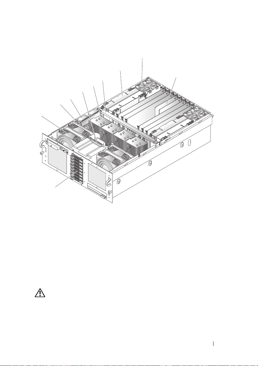
Figure 3-1. Inside the System
1
10
2
8
7
6
5
3
4
9
1 Front fan 2 Intrusion switch
3 RAID controller 4 SAS backplane
5 Processor heat sink 6 Center brace
7 Memory riser 8 Back fan
9 PCI Express card 10 Hard drives
Removing and Installing the Top Cover
CAUTION: If the system is rack mounted, make sure the rack is anchored
securely so it will not tilt forward when the server is extended. A crush hazard
exists if the rack tilts forward. This could cause serious injury and/or death.
Installing System Components 59
Page 60

CAUTION: Only trained service technicians are authorized to remove the system
cover and access any of the components inside the system. See your Product
Information Guide for complete information about safety precautions, working
inside the computer, and protecting against electrostatic discharge.
NOTICE: For proper cooling and airflow, do not operate the server with the cover
removed for more than four minutes. Do not leave the chassis cover open or a
system fan removed any longer than necessary; system cooling could be reduced.
NOTICE: The server comes with a removable top cover that allows the system fans
to be hot-plugged and other system components to be serviced. Except for
components described in this chapter, all servicing must be done by a qualified
service technician.
NOTICE: Provide ElectroStatic Discharge (ESD) protection at all times by wearing
an antistatic wrist strap attached to the any unpainted chassis surface (chassis
ground) when handling electronic components.
Removing the Top Cover
To upgrade or troubleshoot the system, remove the system cover to gain
access to internal components.
1
Unless you are installing a hot-plug component such as a cooling fan or
power supply, remove power from the system and attached peripherals,
and disconnect the system from the electrical outlet and peripherals.
2
To remove the system cover, turn the latch release lock counter-clockwise
to the unlocked position. See Figure 3-2.
3
Lift the latch on top of the system. The cover will slide back as you lift the
latch. See Figure 3-2.
4
Grasp the cover on both sides and carefully lift the cover away from the
system.
Installing the Top Cover
1
Lift up the latch on the cover.
2
Place the cover on top of the system and offset the cover slightly back so
that it clears the chassis J hooks and lays flush on the system chassis. See
Figure 3-2.
3
Push down the latch to lever the cover into the closed position.
4
Rotate the latch release lock in a clockwise direction to secure the cover.
60 Installing System Components
Page 61

Figure 3-2. Removing the Top Cover
3
1
2
1 Latch 2 Latch release lock
3 Alignment J hooks
Installing System Components 61
Page 62

Hard Drives
This subsection describes how to install and configure SAS or SATA hard
drives in the system's internal hard drive bays. Your system features up to five
3.5-inch hard drives, or eight 2.5-inch hard drives. All drives connect to the
system board through one of several optional SAS backplanes. See "Power
Interposer Connectors" on page 160 for information on these backplane
options.
NOTE: Depending on the hard drive configuration you ordered, your hard drive(s)
may come with a drive interposer that allows your SATA drive to attach to the SAS
connector on the backplane.
Before You Begin
Hard drives are supplied in special hot-pluggable SATA drive carriers that fit
in the hard drive bays.
NOTICE: Before attempting to remove or install a drive while the system is running,
see the documentation for the optional SAS RAID controller card to ensure that the
host adapter is configured correctly to support hot-plug drive removal and
insertion.
NOTE: It is recommended that you use only drives that have been tested and
approved for use with the SAS backplane.
You may need to use different programs than those provided with the
operating system to partition and format SAS or SATA hard drives.
NOTICE: Do not turn off or reboot your system while the drive is being formatted.
Doing so can cause a drive failure.
When you format a high-capacity hard drive, allow enough time for the
formatting to be completed. Long format times for these drives are normal.
Removing a Drive Blank
NOTICE: To maintain proper system cooling, all empty hard drive bays must have
drive blanks installed. If you remove a hard drive carrier from the system and do not
reinstall it, you must replace the carrier with a drive blank.
The process for removing a drive blank depends on whether your system is
configured with 3.5-inch or 2.5-inch hard drives.
For 3.5-inch hard drive configurations:
62 Installing System Components
Page 63

1
1
Press the drive blank release in the direction of the arrow.
2
Pry the ends of the blank outward until the blank is free.
For 2.5-inch hard drive configurations, remove the blank as you would the
2.5-inch hard drive carrier:
1
Open the drive blank release handle to release the blank. See Figure 3-3.
2
Slide the drive blank out until it is free of the drive bay.
Figure 3-3. Removing a Drive Blank
1 Release handle
Installing a Drive Blank
The process for installing a drive blank depends on whether your system is
configured with 3.5-inch or 2.5-inch hard drives.
Installing System Components 63
Page 64

For 3.5-inch hard drive configurations, the drive blank is keyed to ensure
correct insertion into the drive bay. To install a 3.5-inch drive blank, insert
and rotate in the keyed side of the blank into the drive bay and press evenly
on the other end of the blank until it is fully inserted and latched.
For 2.5-inch hard drive configurations, install the hard drive blank as a 2.5inch hard drive carrier:
1
Open the handle on the drive blank.
2
Insert the drive blank into the drive bay until the blank is fully seated.
3
Close the handle to lock the blank in place.
Removing a Hot-Plug Hard Drive
NOTICE: To maintain proper system cooling, all empty hard drive bays must have
drive blanks installed.
1
From the RAID management software, prepare the drive for removal and
wait until the hard drive indicators on the drive carrier signal that the drive
can be removed safely. See your SAS RAID controller documentation for
information about hot-plug drive removal.
If the drive has been online, the green activity/fault indicator will flash as
the drive is powered down. When both drive indicators are off, the drive is
ready for removal.
2
Squeeze the carrier handle to unlatch the carrier from the system.
3
Pull the carrier handle away from the system to extract the carrier. See
Figure 3-4.
64 Installing System Components
Page 65

Figure 3-4. Removing a Hot-Plug Hard Drive
2
3
1
1 activity and fault indicators 2 drive carrier release handle
3 hard drive
4
Slide the hard drive out until it is free of the drive bay.
5
If you do not replace the hard drive, insert a drive blank in the vacated
drive bay. See "Installing a Drive Blank" on page 63".
Installing a Hot-Plug Hard Drive
NOTICE: When installing a hard drive, ensure that the adjacent drives are fully
installed. Inserting a hard drive carrier and attempting to lock its handle next to a
partially installed carrier can damage the partially installed carrier's shield spring
and make it unusable.
NOTICE: Not all operating systems support hot-plug drive installation. See the
documentation supplied with your operating system.
Installing System Components 65
Page 66

1
If a drive blank is present in the bay, remove it. See "Removing a Drive
Blank" on page 62.
2
Open the handle on the hard drive carrier.
3
Insert the hard drive carrier into the drive bay until the carrier contacts the
backplane.
4
Close the handle to lock the drive in place.
Replacing a Hard Drive Carrier
Removing a Hard Drive From a Hard Drive Carrier
1
Remove the four screws from the slide rails on the hard drive carrier.
2
Separate the hard drive from the carrier.
Installing a SAS Hard Drive Into a SATAu Drive Carrier
NOTE: SAS hard drives must be installed only in SATAu drive carriers. The SATAu
drive carrier is labeled "SATAu" and also has marks indicating the SAS and SATA
mounting screws.
1
Insert the SAS hard drive into the hard drive carrier with the connector
end of the drive at the back. See Figure 3-5.
2
Viewing the assembly as shown in Figure 3-5, align the bottom back screw
hole on the hard drive with the hole labeled "SAS" on the hard drive carrier.
When aligned correctly, the back of the hard drive will be flush with the
back of the hard drive carrier.
3
Attach the four screws to secure the hard drive to the hard drive carrier. See
Figure 3-5.
66 Installing System Components
Page 67

Figure 3-5. Installing a SAS Hard Drive Into a SATAu Drive Carrier
SATAu SAS
1
2
3
1 Screw (4) 2 Drive carrier
3 Hard drive
Installing a SATA Hard Drive Into a SATAu Hard Drive Carrier
NOTE: The SATAu drive carrier is labeled "SATAu" and also has marks indicating
the SAS and SATA mounting screws.
1
Insert the SATA hard drive into the SATAu hard drive carrier with the
connector end of the drive at the back. See Figure 3-5.
2
Viewing the assembly as shown in Figure 3-5, align the bottom back screw
hole on the hard drive with the hole labeled "SATAu" on the hard drive
carrier.
3
Attach the four screws to secure the hard drive to the hard drive carrier. See
Figure 3-5.
Installing System Components 67
Page 68

Power Supplies
Two p o w e r s u p p li e s power your system.
NOTE: Your system can operate using only one power supply, but with severely
degraded performance.
Removing a Power Supply
NOTICE: The system requires one power supply for the system to operate normally.
The system is in the redundant mode when two power supplies are installed and
both power supplies are connected to an AC power source. Remove and replace
only one power supply at a time in a system that is powered on. Operating the
system with only one power supply installed and without a power supply blank
installed for extended periods of time can cause the system to overheat.
NOTICE: If only one power supply is installed, it must be installed in power supply
bay (1).
NOTICE: If you connect the system to a power source in the range of 120 to 220
VAC, and if two power supplies are installed, the second power supply serves as a
redundant, hot-plug power source.
1
If your system has a single power supply, remove power from the system
and all attached peripherals. For a redundant system, you can leave the
system running and proceed to the next step.
2
Disconnect the power cable from the power source.
3
Disconnect the power cable from the power supply.
4
Depress the power supply latch and then pull the power supply lever to
extract the power supply out of the chassis. See Figure 3-6.
5
Pull the power supply straight out to clear the chassis.
68 Installing System Components
Page 69
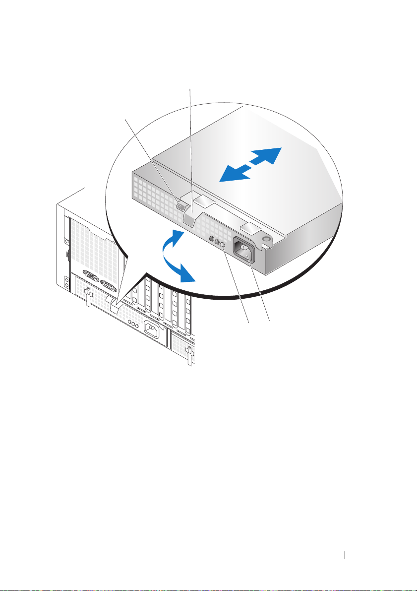
Figure 3-6. Removing a Power Supply
1
2
4
3
1 Power supply latch 2 Power supply lever
3 Power connector 4 Power supply status indicators
Installing a Power Supply
1
With the power-supply lever in the extended position, slide the new power
supply into the chassis. See Figure 3-6.
2
Rotate the lever toward the power supply until it is completely flush with
the power-supply faceplate and the power supply latch engages. See
Figure 3-6.
Installing System Components 69
Page 70

3
Connect the power cable to the power supply, and plug the cable into a
power outlet.
NOTE: After installing a new power supply, allow several seconds for the
system to recognize the power supply and determine whether it is working
properly. The power supply status indicator will turn green to signify that the
power supply is functioning properly. See Figure 3-6.
System Fans
The system includes eight hot-pluggable cooling fans, four in the front and
four in the back.
Four cooling fan are located at the front of the chassis.You can replace each
fan.
Two cooling fan housings are located in the back of the chassis. Each housing
contains two fans. You can replace each fan and each fan housing.
You can replace a failed cooling fan without turning off the power to the
server only if the remaining fans are fully functional.
Removing a Front System Fan
CAUTION: Only trained service technicians are authorized to remove the system
cover and access any of the components inside the system. See your Product
Information Guide for complete information about safety precautions, working
inside the computer, and protecting against electrostatic discharge.
1
Open the system. See "Removing the Top Cover" on page 60.
2
Locate the fan you are removing.
3
Squeeze the fan loop handles to unlatch the fan from the chassis.
4
Pull the fan straight up from the fan cage to clear the chassis.
Installing a Front System Fan
CAUTION: Only trained service technicians are authorized to remove the system
cover and access any of the components inside the system. See your Product
Information Guide for complete information about safety precautions, working
inside the computer, and protecting against electrostatic discharge.
1
Open the system. See "Removing the Top Cover" on page 60.
2
Position the connector on the fan to mate with the connector on the
chassis.
70 Installing System Components
Page 71

3
Position the fan between the chassis guides.
4
Lower the replacement fan into the chassis until it snaps into place.
Hot-plugging a Front System Fan
CAUTION: Only trained service technicians are authorized to remove the system
cover and access any of the components inside the system. See your Product
Information Guide for complete information about safety precautions, working
inside the computer, and protecting against electrostatic discharge.
CAUTION: Use caution when handling the fan until the fan blades stop spinning.
NOTICE: For proper cooling and airflow, do not operate the server with the cover
removed for more than four minutes. Do not leave the chassis cover open or a
system fan removed any longer than necessary; system cooling could be reduced.
NOTICE: The system fans are hot-pluggable. To maintain proper cooling while the
system is on, replace only one fan at a time.
1
Open the system. See "Removing the Top Cover" on page 60.
2
Locate the fan you are replacing.
3
Squeeze the fan loop handles to unlatch the fan from the chassis.
4
Pull the fan straight up from the fan cage to clear the chassis.
5
Position the connector on the replacement fan to mate with the connector
on the chassis.
6
Position the fan between the chassis guides.
7
Lower the replacement fan into the chassis until it snaps into place.
8
Reinstall the top cover.
Installing System Components 71
Page 72

Figure 3-7. Hot-plugging a Front System Fan
2
1
3
4
1 Brace 2 Fan
3 Loop handle 4 Fan connector
Removing a Back System Fan
CAUTION: Only trained service technicians are authorized to remove the system
cover and access any of the components inside the system. See your Product
Information Guide for complete information about safety precautions, working
inside the computer, and protecting against electrostatic discharge.
1
Open the system. See "Removing the Top Cover" on page 60.
2
Locate the fan you are removing.
72 Installing System Components
Page 73

3
Squeeze the fan loop handles to unlatch the fan from the back system fan
housing.
4
Pull the fan straight up from the fan cage to clear the back system fan
housing.
Installing a Back System Fan
CAUTION: Only trained service technicians are authorized to remove the system
cover and access any of the components inside the system. See your Product
Information Guide for complete information about safety precautions, working
inside the computer, and protecting against electrostatic discharge.
1
Open the system. See "Removing the Top Cover" on page 60.
2
Position the connector on the fan to mate with the connector on the
chassis.
3
Position the fan in the fan housing.
4
Lower the replacement fan into the back system fan housing until it snaps
into place.
Hot-plugging a Back System Fan
CAUTION: Only trained service technicians are authorized to remove the system
cover and access any of the components inside the system. See your Product
Information Guide for complete information about safety precautions, working
inside the computer, and protecting against electrostatic discharge.
CAUTION: Use caution when handling the fan until the fan blades stop spinning.
NOTICE: For proper cooling and airflow, do not operate the server with the cover
removed for more than four minutes. Do not leave the chassis cover open or a
system fan removed any longer than necessary; system cooling could be reduced.
NOTICE: The system fans are hot-pluggable. To maintain proper cooling while the
system is on, replace only one fan at a time.
1
Open the system. See "Removing the Top Cover" on page 60.
2
Locate the fan you are replacing.
3
Squeeze the fan loop handles to unlatch the fan from the chassis.
4
Pull the fan straight up from the fan housing to clear the fan housing.
5
Position the connector on the fan to mate with the connector on the
chassis.
Installing System Components 73
Page 74

6
Position the fan in the fan housing.
7
Lower the replacement fan into the housing until it snaps into place.
Removing a Back System Fan Housing
CAUTION: Only trained service technicians are authorized to remove the system
cover and access any of the components inside the system. See your Product
Information Guide for complete information about safety precautions, working
inside the computer, and protecting against electrostatic discharge.
1
Ensure power is removed.
2
Open the system. See "Removing the Top Cover" on page 60.
3
Remove memory risers. See "Removing a Memory Riser" on page 96.
4
Remove applicable back system fans. See "Removing a Back System Fan"
on page 72.
5
Pull the fan housing latch forward and lift back system fan housing clear of
the chassis.
74 Installing System Components
Page 75

Figure 3-8. Removing a Back System Fan Housing
3
2
1
4
1 Fan housing latch 2 Fan housing
3 Fan loop handle 4 Location of fan housing
Installing a Back System Fan Housing
CAUTION: Only trained service technicians are authorized to remove the system
cover and access any of the components inside the system. See your Product
Information Guide for complete information about safety precautions, working
inside the computer, and protecting against electrostatic discharge.
1
Ensure power is removed.
2
Open the system. See "Removing the Top Cover" on page 60.
3
Align fan housing guides with frame.
Installing System Components 75
Page 76

4
Lower the replacement fan housing into the chassis until it snaps into
place.
Cooling Shroud
The cooling shroud directs airflow over the processors.
NOTICE: Never operate your system with the cooling shroud removed. The system
can overheat quickly resulting in a shutdown of the system and the loss of data.
Removing the Cooling Shroud
1
Ensure power is removed.
2
Open the system. See "Removing the Top Cover" on page 60.
3
Grasp the finger holds and lift the cooling shroud straight up. You might
have to lift the corners of the shroud up to disengage the shroud guides
from the chassis.
76 Installing System Components
Page 77
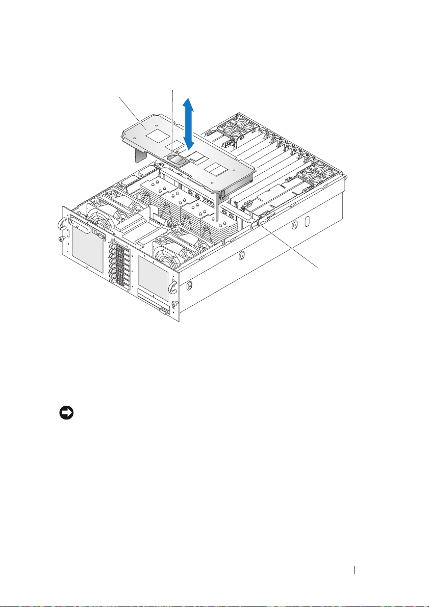
Figure 3-9. Removing the Cooling Shroud
1
3
2
1 Cooling shroud 2 Finger holds
3 Chassis slot
Installing the Cooling Shroud
NOTICE: When installing the cooling shroud, ensure that the shroud does not
damage system cabling.
1
Ensure power is removed.
2
Open the system. See "Removing the Top Cover" on page 60.
3
Position the shroud guides above the slots in the chassis.
4
Gently press the cooling shroud down into place.
Installing System Components 77
Page 78

SAS Controller Card
Your system includes a dedicated slot for a SAS controller card. The SAS
controller card provides the SAS storage subsystem for your system’s internal
hard drives. The optional SAS RAID controller card allows you to set up any
internal hard drives in a RAID configuration. Although the cabling for the
two types of cards is different (the SAS controller card has only one connector,
while the SAS RAID controller card has two), both cards install into the
dedicated slot as described below. The SAS RAID controller card is shown in
Figure 3-10.
78 Installing System Components
Page 79

Figure 3-10. SAS RAID Controller Card
2
4
3
1
1 RAID battery connector 2 Controller connector (2)
3 RAID DIMM 4 Card latch
Installing System Components 79
Page 80

Removing a SAS Controller Card
NOTICE: See "Protecting Against Electrostatic Discharge" in the safety instructions
in your Product Information Guide.
1
Ensure power is removed.
2
Open the system. See "Removing the Top Cover" on page 60.
3
Remove the cooling shroud. See "Removing the Cooling Shroud" on
page 76.
4
Disconnect each controller connector by squeezing the connector latches
and lifting the connector straight up.
NOTICE: Do not lift on SAS RAID DIMM card attached to the SAS controller
card, lift the SAS controller card itself.
5
Push the card latch away from the card and lift on the card out of the
system.
6 Disconnect the RAID battery from the SAS controller card.
Installing an SAS Controller Card
1
Ensure power is removed.
2
Open the system. See "Removing the Top Cover" on page 60.
3
Remove the cooling shroud. See "Removing the Cooling Shroud" on
page 76.
4
Connect the RAID battery to the SAS controller card.
5
Position the SAS controller card between the card guides above the SAS
controller card connector on the system board.
6
Lower the SAS controller card into the chassis until the card is seated on
the system board.
CAUTION: Ensure the RAID battery cabling does not touch the processor
heat sink.
7
Connect each controller connector.
SAS and SAS RAID Controller Card Cabling Guidelines
Ensure that the cabling for the SAS and SAS RAID controller is routed as
shown in Figure 3-11 for 2.5-inch systems and in Figure 3-12 for 3.5-inch
systems.
80 Installing System Components
Page 81

Figure 3-11. 2.5-Inch SAS / SAS RAID Cabling
10
7
6
5
8
9
2
1
4
3
Installing System Components 81
Page 82

1 SAS backplane 2 SAS A connector
3 GND/12V connector 4 Controller 0 connector
5 Controller 1 connector 6 SATA_A connector (on system board)
7 SATA_A connector (on Power
Interposer Board)
9 PIB power connector 10 SAS B connector
8 Power Interposer Board (PIB)
82 Installing System Components
Page 83

Figure 3-12. 3.5-Inch SAS / SAS RAID Cabling
8
4
2
5
6
3
7
1
9
10
Installing System Components 83
Page 84

1 SAS A connector 2 GND/+12V connector
3 SAS backplane 4 SAS B connector
5 Controller 0 connector 6 Controller 1 connector
7 System board 8 SATA_A connector (on system board)
9 SATA_A connector (on SAS
backplane)
10 Control panel connector
RAID Battery
Installing a RAID Battery
1
Insert the RAID battery into the battery carrier. See Figure 3-13.
2
Locate the battery carrier slots at the left of the processors.
3
Place the controller cabling harnesses between the battery carrier clips and
the chassis.
4
Insert the battery carrier and RAID battery into the chassis battery carrier
slots ensuring that the battery carrier is aligned and fully seated in the
slots.
5
Connect the battery cable to the SAS controller card.
84 Installing System Components
Page 85

Figure 3-13. Installing a RAID Battery
1
2
3
1 Mounting hole (2) 2 RAID battery latch
3 Battery carrier guide
Removing a RAID Battery
1
Remove the SAS controller card. See "Removing a SAS Controller Card"
on page 80
2
Pull the RAID battery carrier latch away from the chassis.
3
Lift the RAID battery carrier out of the system.
4
Gently pulling back the two guides holding the RAID battery into the
battery carrier, remove the RAID battery from the battery carrier.
Installing System Components 85
Page 86

Configuring the Boot Device
NOTE: System boot is not supported from an external device attached to a SAS or
SCSI adapter. See support.dell.com for the latest support information about booting
from external devices.
If you plan to boot the system from a hard drive, the drive must be attached
to the primary (or boot) controller. The device that the system boots from is
determined by the boot order specified in the System Setup program.
The System Setup program provides options that the system uses to scan for
installed boot devices. See "Using the System Setup Program" on page 41 for
information about the System Setup program.
PCI Express Add-in Cards
NOTICE: The server must be powered down to install or remove a card from a PCI
Express slot.
CAUTION: Expansion slot covers must be installed over all vacant slots to
maintain the electromagnetic emission characteristics of the server and to ensure
proper system cooling.
Installing a PCI Express Card
CAUTION: Many repairs may only be done by a certified service technician. You
should only perform troubleshooting and simple repairs as authorized in your
product documentation, or as directed by the online or telephone service and
support team. Damage due to servicing that is not authorized by Dell is not covered
by your warranty. Read and follow the safety instructions that came with the
product.
To install a expansion card, perform the following steps:
1
Remove power from the system and attached peripherals, and then
disconnect the system from the electrical outlet.
2
Open the system. See "Removing the Top Cover" on page 60.
3
Open the plastic expansion-card retainer above the filler bracket of the
empty slot. See Figure 3-14.
86 Installing System Components
Page 87

Figure 3-14. Installing and Removing PCI Express Cards
2
1
3
1 Expansion card retainer 2 Card latch
3 Filler bracket
4
Remove the filler bracket on the slot that you are using.
NOTE: Keep the filler bracket if you need to remove the expansion card. Filler
brackets must be installed over empty expansion-card slots to maintain
Federal Communications Commission (FCC) certification of the system. The
brackets also keep dust and dirt out of the system and aid in proper cooling
and airflow inside the system.
5
Insert the expansion card firmly into the expansion-card connector until
the card is fully seated.
Installing System Components 87
Page 88

NOTE: Ensure that the expansion-card bracket is also inserted into the
securing slot at the bottom of the bracket slot.
6
Close the expansion-card retainer. See Figure 3-14.
7
Connect any internal or external cable(s) to the expansion card.
8
Close the system. See "Installing the Top Cover" on page 60.
Removing a PCI Express Card
CAUTION: Many repairs may only be done by a certified service technician. You
should only perform troubleshooting and simple repairs as authorized in your
product documentation, or as directed by the online or telephone service and
support team. Damage due to servicing that is not authorized by Dell is not covered
by your warranty. Read and follow the safety instructions that came with the
product.
1
Remove power from the system and attached peripherals, and disconnect
the system from the electrical outlet.
2
Open the system. See "Removing the Top Cover" on page 60.
3
Disconnect any internal or external cable(s) that are connected to the
expansion card.
4
Open the expansion-card retainer adjacent to the slot. See Figure 3-14.
5
Press the card latch away from the expansion card, grasp the card, and
carefully lift it from the system-board connector.
6
If you are permanently removing the card, replace the metal filler bracket
over the empty card-slot opening.
7
Close the expansion-card retainer. See Figure 3-14.
8
Close the system. See "Installing the Top Cover" on page 60.
Optical Drive
The system accommodates one optical drive. The device is not hot-pluggable,
so the system must be powered down and the power cords removed from the
chassis before installing or removing this drive.
Removing the Optical Drive
1
Remove power from the system and attached peripherals, and then
disconnect the system from the electrical outlet.
88 Installing System Components
Page 89

2
1
2
Pull the locking handle until the drive releases from the chassis. See
Figure 3-15.
3
Remove the drive from the chassis.
Figure 3-15. Removing the Optical Drive
1 Optical drive 2 Locking handle
Installing the Optical Drive
1
Insert the drive fully into the chassis until it snaps into place.
2
Push the locking handle into the drive to lock the drive into the chassis.
Installing System Components 89
Page 90

Replacing an Optical Drive Mounting Tray
Removing an Optical Drive From an Optical Drive Mounting Tray
1
Remove the optical drive from the system. See "Removing the Optical
Drive" on page 88.
2
Disconnect the ribbon cable from the back of the optical drive. See
Figure 3-16.
90 Installing System Components
Page 91

Figure 3-16. Optical Drive and Optical Drive Mounting Tray
10
1
2
5
4
8
7
9
6
3
1 Optical drive 2 Ribbon cable
3 Hole in optical drive 4 Retaining screw
5 Retaining bracket 6 Alignment pin
7 Retaining bracket tab 8 Mounting tray notch
9 Alignment pin (left side) 10 Mounting tray
3
4
5
Unscrew the optical drive retaining screw.
Pull the retaining bracket away from the optical drive.
Remove the optical drive from the optical drive mounting tray.
Installing System Components 91
Page 92

Installing an Optical Drive Into an Optical Drive Mounting Tray
1
Slide the optical drive onto the left side alignment pins of the optical drive
mounting tray.
2
Angle the retaining bracket tab into the optical drive mounting tray notch.
3
Press the retaining bracket against the optical drive, ensuring the
alignment pin engages the optical drive hole.
NOTE: The alignment pin on the
drive.
4
Screw the optical drive retaining screw into the optical drive mounting
tray.
5
Connect the ribbon cable to the back of the optical drive.
retaining bracket must engage a hole in the optical
System Memory
The system supports x4 or x8, single- or dual-rank fully buffered 667 MT/s (55-5 latency) DDR2 DIMMs in 512 MB, 1 GB, 2 GB, or 4 GB packages.
Four memory risers must be installed at all times. The risers connect to the
main board through x16 PCI Express connectors.
General Memory Module Installation Guidelines
AC power must be removed from the system before servicing the memory
risers.
NOTICE: For proper cooling, each memory riser must be fully populated with
DIMMs or blanks or a combination thereof.
Four memory risers with one DIMM per riser must be installed for the server
to function.
Supported memory riser configurations are as follows:
• All DIMMs must be FBD using DDR2 DRAMs (FBD Generation 1).
• In all cases, DIMMs must be installed starting with the lowest number slot
in a given channel (i.e., install DIMM1 first).
• In non-Mirrored Mode, all DIMMs with the same slot number within a
given branch must match (size, technology, etc.). It is not required to
match DIMMs between different slot numbers.
92 Installing System Components
Page 93

• Mirrored mode requires the same DIMM type across and up-and-down
channels.
• In Single Channel Mode, a DIMM must be populated in the Branch 0,
Channel A, DIMM 1 slot first, then you can populate the Channel A up to
all 8 DIMMs.
• For the Dual Channel Mode, the memory capacity upgrade path would be
to populate Branch 0 of Channel A and Channel B with the same DIMM
number and type, or Branch 1 of Channel C and Channel D with the same
DIMM number and type.
Non-Optimal Memory Configurations
System performance can be affected if your memory configuration does not
conform to the preceding installation guidelines. Your system may issue an
error message during startup stating that your memory configuration is nonoptimal.
The server will support a population of DIMMs with different speed ratings.
The overall system memory speed will be determined by the slowest DIMM
populated.
The server will support population of mixed memory suppliers, provided all
other rules above are followed.
Memory Sparing Support
The system supports memory sparing if eight identical memory modules are
installed in the system. The memory sparing feature must be enabled in the
System Setup program and can be used only if memory mirroring is not
enabled.
Memory sparing allocates four ranks of DIMM memory to the spare bank.
These four ranks consist of the first rank of memory in DIMM sockets 1
through 4. For single-rank DIMMs, the entire capacity of the four DIMMs is
allocated to sparing whereas for dual-rank DIMMs, only half of the fourDIMM capacity is allocated to sparing. Table 3-1 shows how memory sparing
splits the available and spared memory in each of the single- and dual-ranked
memory module combinations.
Installing System Components 93
Page 94

Memory Mirroring Support
The system supports memory mirroring if 16 identical memory modules are
installed in the system. Mirroring must be enabled in the System Setup
program and can be used only if memory sparing is not enabled. In a mirrored
configuration, the total available system memory is one-half of the total
installed memory.
Table 3-1. Valid Memory Configurations
Branch 0 Branch 1
Number of
DIMMS
1 DIMM A1 (riser only) (riser only) (riser only) None
4 DIMM A1 DIMM B1 DIMM C1 DIMM D1 None
8 DIMM A1
12 DIMM A1
16 DIMM A1
20 DIMM A1
Channel 0
(Riser A)
DIMM A2
DIMM A2
DIMM A3
DIMM A2
DIMM A3
DIMM A4
DIMM A2
DIMM A3
DIMM A4
DIMM A5
Channel 1
(Riser B)
DIMM B1
DIMM B2
DIMM B1
DIMM B2
DIMM B3
DIMM B1
DIMM B2
DIMM B3
DIMM B4
DIMM B1
DIMM B2
DIMM B3
DIMM B4
DIMM B5
Channel 2
(Riser C)
DIMM C1
DIMM C2
DIMM C1
DIMM C2
DIMM C3
DIMM C1
DIMM C2
DIMM C3
DIMM C4
DIMM C1
DIMM C2
DIMM C3
DIMM C4
DIMM C5
Channel 3
(Riser D)
DIMM D1
DIMM D2
DIMM D1
DIMM D2
DIMM D3
DIMM D1
DIMM D2
DIMM D3
DIMM D4
DIMM D1
DIMM D2
DIMM D3
DIMM D4
DIMM D5
Available Redundant
Memory Modes
None
None
Spare Mode / Mirror
Mode
Spare Mode / Mirror
Mode
94 Installing System Components
Page 95

Table 3-1. Valid Memory Configurations
Branch 0 Branch 1
Number of
DIMMS
24 DIMM A1
28 DIMM A1
32 DIMM A1
Channel 0
(Riser A)
DIMM A2
DIMM A3
DIMM A4
DIMM A5
DIMM A6
DIMM A2
DIMM A3
DIMM A4
DIMM A5
DIMM A6
DIMM A7
DIMM A2
DIMM A3
DIMM A4
DIMM A5
DIMM A6
DIMM A7
DIMM A8
Channel 1
(Riser B)
DIMM B1
DIMM B2
DIMM B3
DIMM B4
DIMM B5
DIMM B6
DIMM B1
DIMM B2
DIMM B3
DIMM B4
DIMM B5
DIMM B6
DIMM B7
DIMM B1
DIMM B2
DIMM B3
DIMM B4
DIMM B5
DIMM B6
DIMM B7
DIMM B8
Channel 2
(Riser C)
DIMM C1
DIMM C2
DIMM C3
DIMM C4
DIMM C5
DIMM C6
DIMM C1
DIMM C2
DIMM C3
DIMM C4
DIMM C5
DIMM C6
DIMM C7
DIMM C1
DIMM C2
DIMM C3
DIMM C4
DIMM C5
DIMM C6
DIMM C7
DIMM C8
Channel 3
(Riser D)
DIMM D1
DIMM D2
DIMM D3
DIMM D4
DIMM D5
DIMM D6
DIMM D1
DIMM D2
DIMM D3
DIMM D4
DIMM D5
DIMM D6
DIMM D7
DIMM D1
DIMM D2
DIMM D3
DIMM D4
DIMM D5
DIMM D6
DIMM D7
DIMM D8
Available Redundant
Memory Modes
Spare Mode / Mirror
Mode
Spare Mode / Mirror
Mode
Spare Mode / Mirror
Mode
NOTE: The single DIMM configuration is for troubleshooting.
Installing System Components 95
Page 96

Removing a Memory Riser
CAUTION: Only trained service technicians are authorized to remove the system
cover and access any of the components inside the system. See your Product
Information Guide for complete information about safety precautions, working
inside the computer, and protecting against electrostatic discharge.
1
Ensure power is removed.
2
Open the system. See "Removing the Top Cover" on page 60.
3
Push the memory riser latches toward the ends of the memory riser. See
Figure 3-17.
4
Lift the memory riser latches to raise the memory riser away from the
system board.
5
Lift the memory riser out of the system.
96 Installing System Components
Page 97

Figure 3-17. Removing a Memory Riser
1
2
3
4
5
1 Memory riser cover 2 System board connector
3 Memory riser card 4 Memory riser latch
5 Back fan housing
Installing System Components 97
Page 98

Installing a Memory Riser
CAUTION: Only trained service technicians are authorized to remove the system
cover and access any of the components inside the system. See your Product
Information Guide for complete information about safety precautions, working
inside the computer, and protecting against electrostatic discharge.
1
Ensure power is removed.
2
Open the system. See "Removing the Top Cover" on page 60.
3
Ensure the memory riser latches are rotated away from the memory riser.
4
Align the memory riser connector with the connector on the system board.
5
Lower the memory riser until the memory riser latches engage the chassis
(in front) and the back fan housing.
6
Press down on the memory riser latches to lever the memory riser onto the
system board.
Memory Population Rules
• Memory must be populated beginning with Memory Riser_A, slot 1. This
is DIMM slot A1. Memory Riser_A is at the right side of the system.
• To increase memory capacity, additional memory can be added to Memory
Riser_A beginning with slot A2, and followed by slot A3 and then slot A4.
• Additional memory can be added by installing identical pairs of DIMMs in
the lowest numbered available slots.
• Identically numbered FBDIMM sockets for both memory risers in a
branch must be populated with FBDIMMs identical in terms of timing,
technology, and size. For example, DIMM A1 and B1 must be identical,
and DIMM C1 and D1 must be identical.
• FBDIMMs installed in different socket positions (numbers) on a memory
riser do not need to be identical. For example, DIMMs A1 and B1 can be
different from DIMMs A2 and B2.
• If memory mirroring is not required, FBDIMMs installed in the same
socket positions (numbers) across the two branches do not need to be
identical. For example, DIMMs A1 and B1 can be different from DIMMs
C1 and D1.
98 Installing System Components
Page 99

• If memory mirroring is required, FBDIMMs installed in the same socket
positions (numbers) across the two branches must be identical. For
example, DIMMs A1 and B1 must be identical to DIMMs C1 and D1.
• Additional memory can be added by installing identical pairs of DIMMs in
the lowest numbered available slots.
Removing the Memory Riser Cover
1
Ensure power is removed.
2
Remove the top cover. See "Removing the Top Cover" on page 60.
3
Remove the memory riser. See "Removing a Memory Riser" on page 96.
4
Press down on the memory board cover hooks, straddling the memory
board slot connector on the underside of the memory board.
5
Pull the cover away from the memory riser.
6
Lift the memory riser DIMM cover from the memory riser.
NOTE: To install a Memory Riser cover, reverse the removal steps.
Installing Memory Modules
CAUTION: Use extreme care when installing a DIMM. Applying too much
pressure can damage the connector. DIMMs are keyed and can be inserted in only
one way.
CAUTION: Hold DIMMs only by the edges. Do not touch the components or gold
edge connectors.
CAUTION: Install DIMMs with gold-plated edge connectors only.
CAUTION: The maximum DIMM height is 4.445 cm (1.75 inches). Do not install
DIMMs that exceed this height.
1
Open the plastic levers on each end of the DIMM socket(s). Remove the
DIMM from its antistatic container. Hold the DIMM only by the edges.
Do not touch the components or gold edge connectors.
2
Install DIMMs in the correct order. See "Memory Population Rules" on
page 98.
3
Position the DIMM above the socket. Align the notch on the bottom edge
of the DIMM with the key in the DIMM socket.
Installing System Components 99
Page 100

Figure 3-18. Installing Memory Modules
2
1
3
4
5
6
1 Memory riser latch 2 Memory riser
3 DIMM socket lever 4 DIMM socket
5 Memory riser tab 6 Memory riser cover
4
Insert the bottom edge of the DIMM into the socket.
5
Push down on the top edge of the DIMM. The levers at each end of the
DIMM socket will close. Make sure the levers close securely.
6
Lower the memory riser DIMM cover over the DIMM slots.
7
Line up the hooks in the memory riser cover with the notches on the
bottom edge of the memory riser.
8
Lift the memory riser cover over the DIMMs and let the cover latch snap
100 Installing System Components
into place.
9
Install the memory riser. See "Installing a Memory Riser" on page 98.
 Loading...