


TM
Dell
Notes, Notices, and Cautions
NOTE: A NOTE indicates important information that helps you make better use of your computer.
XFR630 with Touch
Fully Rugged Notebook
Quick Reference Guide
NOTICE: A NOTICE indicates either potential damage to hardware or loss of data and tells you how to avoid the
problem.
CAUTION: A CAUTION indicates a potential for property damage, personal injury, or death.
WARNING: A WARNING indicates a potentially hazardous situation which, if not avoided, could result
in death or serious injury.
Information in this document is subject to change without notice.
© 2007 Dell Incorporated. All rights reserved.
Reproduction in any manner whatsoever without the written permission of Dell Incorporated is strictly forbidden.
This document is provided for informational purposes only, and may contain typographical errors and technical inaccuracies. The content is
provided as is, without express or implied warranties of any kind.
Trademarks used in this text: Dell, the DELL logo, Latitude, Wi - Fi Catcher, and ExpressCharge are registered trademarks of Dell Inc.;
Augmentix and the Augmentix logo are registered trademarks of Augmentix Corporation; Xtreme Terrain Grade (XTG), Rugged Redefined,
QuadCool, Armored Protection System (APS), and DirectVue are trademarks of Augmentix Corporation; Microsoft, Windows and Windows Vista
are registered trademarks of Microsoft Corporation; Touchkit is a trademark of eGalax_eMPIA Technology Inc. (EETI).
Other trademarks and trade names may be used in this document to refer to either the entities claiming the marks and names or their
products. Dell Incorporated disclaims any proprietary interest in trademarks and trade names other than its own.
Table of Contents
1 FINDING INFORMATION
2 SETTING UP YOUR COMPUTER
2.1 PROTECTIVE DOORS
2.1.1 Compartment Door
2.1.2 Hinged Door
2.1.3 Friction Fit Door
2.2 INITIAL COMPUTER SETUP
3 ABOUT YOUR COMPUTER
3.1 FRONT VIEW
3.2 LEFT SIDE VIEW

3.3
FIGURE 3 12 XFR630 DOCKING DEVICE CONNECTOR DOOR IN OPEN/SECURED POSITION
RIGHT SIDE VIEW
3.4 BACK VIEW
3.5 BOTTOM VIEW
3.5.1 Accessing the Battery Compartment
3.5.2 Accessing the Docking Device Connector
3.5.3 Accessing the Hard Disk Drive Compartment
4 DIRECTVUETM TOUCH DISPLAY INFORMATION
4.1.1 Touchkit Configuration Utility
5 USING A BATTERY
5.1 BATTERY PERFORMANCE
5.2 CHECKING THE BATTERY CHARGE
5.2.1 Dell™ QuickSet Battery Meter
5.2.2 Microsoft® Windows® Power Meter
5.2.3 Charge Gauge
5.3 LOW-BATTERY WARNING
5.4 CHARGING THE BATTERY
5.5 STORING A BATTERY
6 TROUBLESHOOTING
6.1 LOCKUPS AND SOFTWARE PROBLEMS
6.1.1 The Computer Does Not Start Up
6.1.2 The Computer Stops Responding
6.1.3 A Program Stops Responding or Crashes Repeatedly
6.1.4 A Program is Designed for an Earlier Microsoft® Windows® Operating System
6.1.5 A Solid Blue Screen Appears
6.1.6 Other Software Problems
6.2 DELL DIAGNOSTICS
6.2.1 When to Use the Dell Diagnostics
6.2.2 Starting the Dell Diagnostics From Your Hard Drive
6.2.3 Starting the Dell Diagnostics From the Drivers and Utilities CD
6.2.4 Dell Diagnostics Main Menu
Table of Figures
FIGURE 2 1 REMOVING A COMPARTMENT DOOR
FIGURE 2 2 SAMPLE HINGED DOOR
FIGURE 2 3 SAMPLE FRICTION FIT DOOR
FIGURE 2 4 CONNECTING THE AC ADAPTER
FIGURE 3 1 FRONT VIEW OF XFR630
FIGURE 3 2 XFR LEFT SIDE WITH CONNECTORS/DEVICES PROTECTED
FIGURE 3 3 XFR LEFT PANEL WITH CONNECTORS/DEVICES REVEALED
FIGURE 3 4 XFR RIGHT SIDE WITH CONNECTORS/DEVICES PROTECTED
FIGURE 3 5 XFR RIGHT SIDE WITH CONNECTORS/DEVICES REVEALED
FIGURE 3 6 XFR BACK VIEW WITH CONNECTORS PROTECTED
FIGURE 3 7 XFR BACK VIEW WITH CONNECTORS REVEALED
FIGURE 3 8 XFR BOTTOM VIEW WITH CONNECTORS/DEVICES PROTECTED
FIGURE 3 9 ACCESSING THE BATTERY COMPARTMENT
FIGURE 3 10 OPENING THE XFR630 DOCKING DEVICE CONNECTOR DOOR – STEP 1
FIGURE 3 11 OPENING THE XFR630 DOCKING DEVICE CONNECTOR DOOR – STEP 2
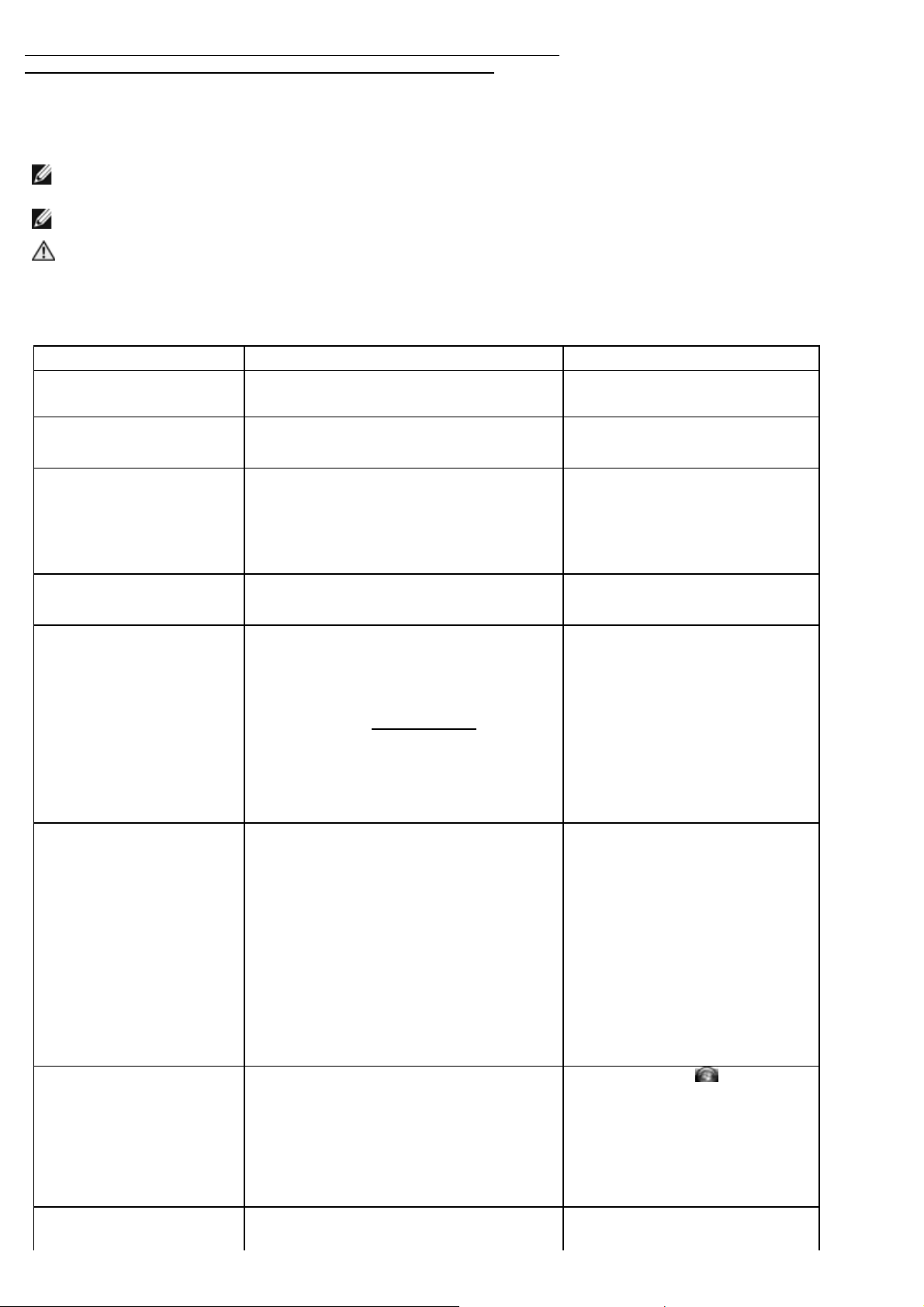
FIGURE 3 13 CLOSING THE XFR630 DOCKING DEVICE CONNECTOR DOOR
FIGURE 3 14 ACCESSING THE HARD DISK DRIVE COMPARTMENT
1 Finding Information
NOTE: Some features or media may be optional and may not ship with your computer. Some features or media
may not be available in certain countries.
NOTE: Additional information may ship with your computer.
CAUTION: The XFR630 with Touch Fully Rugged Notebook User’s Guide provides important safety and
regulatory information. The XFR630 with Touch Fully Rugged Notebook User’s Guide is located in the
‘Open Me First’ envelope provided in your ship container, and can also be located on the Documentation
and Drivers CD.
Documentation Purpose Document Location
‘Open Me First’ Envelope
XFR630 with Touch Fully
Rugged Notebook Quick
Reference Guide
XFR630 with Touch Fully
Rugged Notebook User’s
Guide
Documentation and Drivers
CD
Dell Drivers and Utilities CD
(optional)
Operating System CD
(optional)
Windows Help and Support
Center
Service Tag
Provides a single location where the
documentation and CDs shipped with the
XFR630 Notebook can be located
Guides you through your initial XFR630 with
Touch Notebook setup
·
How to configure your system settings
How to troubleshoot and solve problems
·
How to remove/replace parts
·
Specifications
·
Safety and regulatory information
·
Customer Care Program information
·
The Documentation and Drivers CD contains:
Product documentation
·
Supplemental Dell documentation
·
NOTE: The Drivers and Utilities CD is
optional and may not ship with your
computer.
Documentation and drivers are already
installed on your computer. You can use the
media to reinstall drivers and to run Dell
Diagnostics (see "Dell Diagnostics
").
Readme files may be included on your media
to provide last-minute updates about
technical changes to your computer
or advanced technical reference
material for technicians or experienced
users.
NOTE: The Operating System CD is optional
and may not ship with your computer.
How to reinstall your operating system
How to use Windows operating system
·
How to work with programs and files
·
How to personalize your desktop
·
The Service Tag is located on the bottom of
your computer. Use the Serial Number on
In the ship container
·
In the ship container
·
Available on the Documentation
·
and Driver CD
· Available in the ‘Open Me First’
envelope
Available on the Documentation
·
and Driver CD
Available online
·
Available in the ‘Open Me First’
·
envelope
Optionally available in the
·
‘Open Me First’ envelope
Optionally available in the ‘Open Me
First’ envelope.
The operating system is already
installed on your computer. To
reinstall your operating system, use
the Operating System CD. See
"Restoring Your Operating System"
in your XFR630 with Touch Fully
Rugged Notebook User’s Guide.
After you reinstall your operating
system, use the optional Drivers
and Utilities media to reinstall
drivers for the devices that came
with your computer. Your operating
system product key label is located
in the ‘Open Me First’ envelope.
1. Click Start or à Help and
Support
Type a word or phrase that
2.
describes your problem and
click the arrow icon
Click the topic that describes
3.
you problem
Follow the instructions on the
4.
screen
This label is located on your
computer.
1
your Service Tag to identify your computer
Microsoft Windows License
Label
Dell Support Utility
Dell Quickset Help
Warranty Document Limited Warranty for the XFR630 with Touch
when you contact Customer Support
This label contains your Microsoft Windows
License information.
Software upgrades and troubleshooting hints,
frequently asked questions, hot topics, and
general health of your computer
Information on network activity, the Power
Management Wizard, hotkeys, and other
items controlled by Dell QuickSet
This label is located on your
computer.
The Dell Support Utility automated
upgrade and notification system is
installed on your computer. This
utility provides real -time health
scans of your computing
environment, software updates, and
relevant self-support information.
Access the Dell Support Utility from
icon in the taskbar. For more
the
information, see "Dell Support
Utility" in your XFR630 with Touch
Fully Rugged Notebook User’s
Guide.
To view Dell QuickSet Help , rightclock the QuickSet icon in the
Microsoft Windows taskbar.
For more information on Dell
QuickSet, see “Dell QuickSet in your
XFR630 with Touch Fully Rugged
Notebook User’s Guide .
Available in the ‘Open Me First’
·
envelope
Available on the Documentation
·
and Driver CD
2 Setting Up Your Computer
CAUTION: Before you begin any of the procedures in this section, follow the Safety Information in the
XFR630 with Touch Fully Rugged Notebook User’s Guide.
2.1 Protective Doors
The XFR630 utilizes 3 types of doors to provide a secure and protected environment for the connectors and devices of the
notebook. The 3 types of doors are:
Compartment Door
·
·
Hinged Door
·
Friction Fit Door
For further information regarding replacing a door, refer to the XFR630 with Touch Fully Rugged Notebook User’s Guide.
2.1.1 Compartment Door
Compartment doors are utilized to protect devices located on the bottom of the computer, such as those used for the
battery and hard disk drive.
Figure 2 1 Removing a Compartment Door
The figure above shows the sequence to remove a compartment door. Two quarter-turn latches are used to secure each
compartment door to the computer. The removal of both the battery and disk compartment doors is shown.
To remove a compartment door follow these steps:
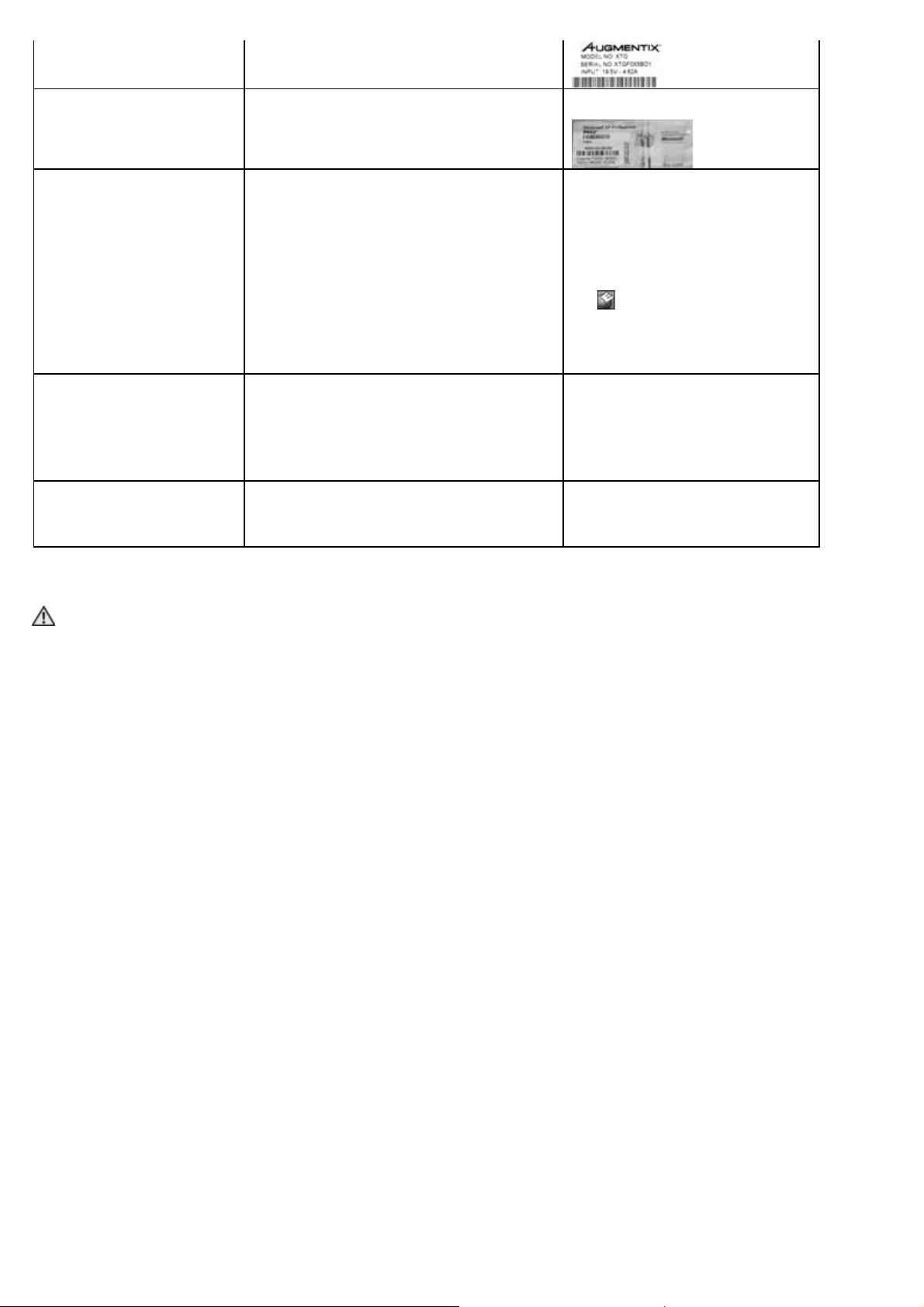
The two quarter-turn latches on the compartment door can be secured with optional M2 screws. If the screws
1.
are present, remove them using a #1 Philips screw driver. If not, proceed to step 2.
2. Lift the handle on the latch.
Turn the latch a quarter-turn in the direction of the ‘unlock’ icon.
3.
Lift the compartment door away from the system.
4.
Reverse this procedure to replace and secure the compartment door.
5.
2.1.2 Hinged Door
Figure 2 2 Sample Hinged Door
1 Hinged door 2 Latch locking mechanism 3
The hinged door is utilized on doors on the back and side panels of the computer. The hinged door is secured by a sliding
latch
The devices and/or connectors protected by these doors can be accessed by pushing the latch in the direction indicated by
the arrow and then rotating the door away from the computer along its hinge. The door can be closed by rotating the
door back along its hinge toward the computer, and pushing the latch until it is secured.
The latch on the hinged door can also be locked by sliding the lock on the latch up to the locked position as shown in the
figure above.
Arrow shows latch release
direction
2.1.3 Friction Fit Door
Figure 2 3 Sample Friction Fit Door
This type of door is utilized on connectors and devices on the back and side panels of the computer.
The devices and/or connectors protected by these doors can be accessed by lifting the door away from the system and
rotating it along the seam. Reverse this procedure to close and secure the friction fit door.
2.2 Initial Computer Setup
Unpack the accessories box and the ‘Open Me First’ envelope.
1.
Set aside the contents of the accessories box and the ‘Open Me First’ envelope, which you will need to complete
2.
the setup of your computer.
The accessories box and ‘Open Me First’ envelope also contain user documentation and any software or additional
hardware (such as PC Cards, drives, or batteries) that you have ordered.
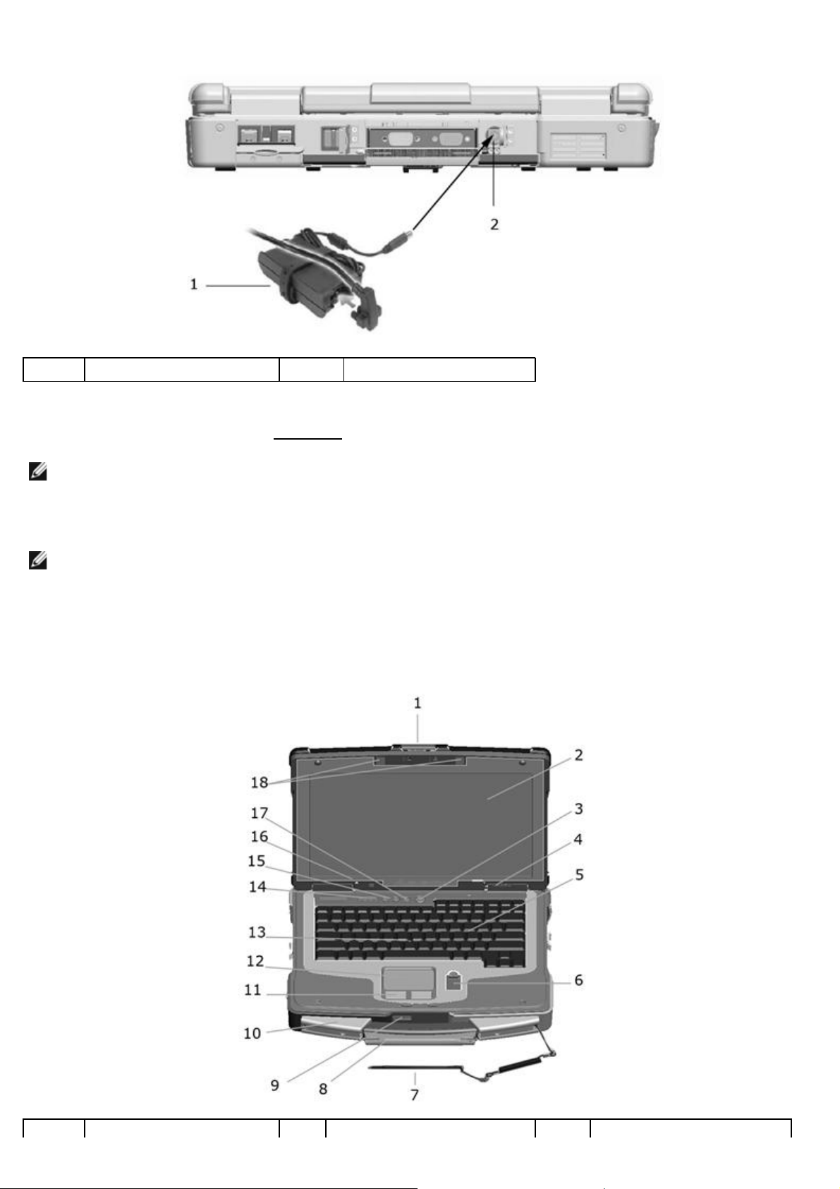
Connect the AC adapter to the AC adapter connector on the back of the computer and to the electrical outlet. To
3.
access the AC adapter connector on the back of the computer, the cover over the connector will need to be
rotated away from the connector. See the figure below for the location of the AC adapter connector.
Figure 2 4 Connecting the AC Adapter
DirectVueTM Display or
1 AC adapter 2 AC adapter connector
Open the computer display by pressing on the display latch and lifting the display. Then press the power button
4.
to turn on the computer. See "Front View
NOTE: It is recommended that you turn on and shut down your computer at least once before you install any cards
or connect the computer to a docking device or other external device, such as a printer.
" for the power button’s location.
3 About Your Computer
NOTE: For additional information about the functions and use of the features identified in this section, see the
XFR630 with Touch Fully Rugged Notebook User’s Guide.
3.1 Front View
Figure 3 1 Front View of XFR630

1 Display latch 2
DirectVue
3 Power button
4 Device status lights 5 Keyboard 6
7
10 Handle 11
13 Track stick 14 Keyboard status lights 15 Volume control buttons
16 Ambient light sensor (ALS) 17 Mute button 18 Keyboard illumination lights
Stylus and stylus tether
(with Touch Display option)
CAUTION: The optional DirectVueTM Touch Display has been designed to accept finger touch as well as
passive stylus input directly onto the screen. With the optional DirectVueTM Touch Display, a stylus is
included with the XFR630 for use in selecting items on the touch screen. Other pointing devices can be
used with the touch screen such as any non -abrasive, smooth or blunt object that will not damage the
touch screen display. The touch screen surface can be damaged by ink pens, marker pens or other
pointed or abrasive objects. The use of non -approved input devices that cause damage to the digitizer
or LCD may not be covered by the limited warranty.
NOTE: For further information on the use and configuration of the DirectVue Touch Display, please refer to the
XFR630 with Touch Fully Rugged Notebook User’s Guide.
8
Stylus housing (with Touch
Display option)
Touch pad/Track stick
buttons
TM
Touch Display
Biometric (fingerprint)
9 Speaker
12 Touch pad
reader - optional
3.2 Left Side View
CAUTION: Do not block, push objects into, or allow dust to accumulate in the air vents. Do not store
your computer in a low-airflow environment, such as a closed briefcase, while it is running. Restricting
the airflow can damage the computer or cause a fire.
The Air Vents are part of the QuadCoolTM Thermal Management System. They provide external venting
of internal heat via the enhanced convection cooling system.
Figure 3 2 XFR630 Left Side with Connectors/Devices Protected
The connectors and devices on the computer are protected from ingress by dense magnesium hinged and friction fit
doors. This protection is a component of the Armored Protection SystemTM (APS).

Figure 3 3 XFR630 Left Panel with Connectors/Devices Revealed
1
4
7 PC card/ExpressCard slot
The following is applicable to UL 1604 and CSA C22.2 No. 213 compliant systems:
Air vents (protected from
ingress)
Smart card slot (with
blank)
WARNING - Explosion Hazard - Do not disconnect equipment unless power has been removed or the
area is known to be non-hazardous
WARNING - Explosion Hazard - Do not utilize any of the connectors/hubs unless area is known to be
non-hazardous
2 Security cable slot 3 Audio connectors (2)
5 1394 connector 6 Wireless switch
3.3 Right Side View
Figure 3 4 XFR630 Right Side with Connectors/Devices Protected

The connectors and devices on the computer are protected from ingress by dense magnesium hinged and friction fit
doors. This protection is a component of the Armored Protection System (APS).
Figure 3 5 XFR630 Right Side with Connectors/Devices Revealed
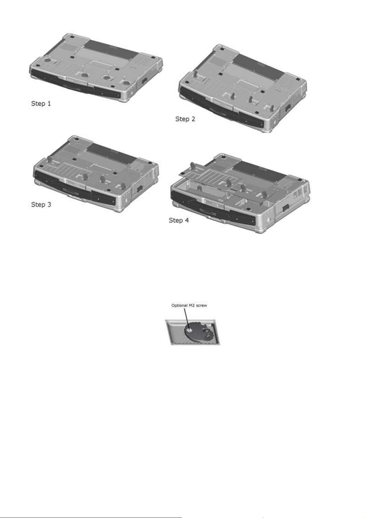
1 XBay expansion bay 2 XBay device latch release 3 USB connectors (2)
The following is applicable to UL 1604 and CSA C22.2 No. 213 compliant systems:
WARNING - Explosion Hazard - Do not disconnect equipment unless power has been removed or the
area is known to be non-hazardous
WARNING - Explosion Hazard - Do not utilize any of the connectors/hubs unless area is known to be
non-hazardous
3.4 Back View
CAUTION: Do not block, push objects into, or allow dust to accumulate in the air vents. Do not store
your computer in a low-airflow environment, such as a closed briefcase, while it is running. Restricting
the airflow can damage the computer or cause a fire.
The Air Vents are part of the QuadCoolTM Thermal Management System. They provide external venting of
internal heat via the enhanced convection cooling system.
Figure 3 6 XFR630 Back View with Connectors Protected

The connectors and devices on the computer are protected from ingress by dense magnesium hinged and friction fit
doors. This protection is a component of the Armored Protection SystemTM (APS).
Figure 3 7 XFR630 Back View with Connectors Revealed
1
4 Serial connector 5 Video connector 6 AC adapter connector
7
The following is applicable to UL 1604 and CSA C22.2 No. 213 compliant systems:
Network connector
(RJ-45)
Air vents (protected from
ingress)
WARNING - Explosion Hazard - Do not disconnect equipment unless power has been removed or the
area is known to be non-hazardous
WARNING - Explosion Hazard - Do not utilize any of the connectors/hubs unless area is known to be
non-hazardous
2
Modem connector
(RJ-11)
3 USB connectors (2)
3.5 Bottom View
Figure 3 8 XFR630 Bottom View with Connectors/Devices Protected

1
4 Battery compartment cover
The compartments on the bottom of the computer are protected from ingress by dense magnesium compartment doors.
This protection is a component of the Armored Protection System.
The following is applicable to UL 1604 and CSA C22.2 No. 213 compliant systems:
Docking device connector
door
WARNING - Explosion Hazard - Do not disconnect equipment unless power has been removed or the
area is known to be non-hazardous
WARNING - Explosion Hazard - Do not utilize any of the connectors/hubs unless area is known to be
non-hazardous
2 Memory module cover 3
Hard disk drive
compartment cover
3.5.1 Accessing the Battery Compartment
Figure 3 9 Accessing the Battery Compartment

3.5.1.1 Removing the Battery
CAUTION: Before performing these procedures, turn off the computer, disconnect the AC adapter from
the electrical outlet and the computer, disconnect the modem from the wall connector and computer,
and remove any other external cables from the computer.
CAUTION: Using an incompatible battery may increase the risk of fire or explosion. Replace the battery
only with a compatible battery purchased from Dell. The battery is designed to work with your
computer. Do not use a battery from other computers with your computer.
NOTICE: You must remove all external cables from the computer to avoid possible connector damage. For
information about replacing the second battery, if applicable, see "XBay" in your XFR630 with Touch Fully Rugged
Notebook User’s Guide.
The following is applicable to UL 1604 and CSA C22.2 No. 213 compliant systems:
WARNING - Explosion Hazard - Do not disconnect equipment unless power has been removed or the
area is known to be non-hazardous
WARNING - To prevent ignition of a hazardous atmosphere, batteries must only be changed or charged
an area known to be non-hazardous
To remove the battery:
If the computer is connected to a docking device (docked), undock it. See the documentation that came with your
1.
docking device for instructions.
Ensure that the computer is turned off.
2.
If the 2 screws that secure the quarter-turn latches are installed, remove the 2 screws on the latches on the
3.
battery compartment utilizing a #1 Philips screw driver. See “Bottom View
compartment. If the 2 security screws are not installed, proceed to step 4.
Lift each latch and turn each a quarter-turn, toward the ‘unlock’ icon, to release the latching mechanism. Remove
4.
the compartment cover from the computer.
To remove the battery from the compartment, utilize the tab on the battery to assist in lifting the battery from the
5.
compartment.
To replace the battery, follow the removal procedure in the reverse order.
For additional information regarding battery operation, see the section ‘Using a Battery
” for the location of the battery
’.
3.5.2 Accessing the Docking Device Connector
You must prepare your XFR630 with Touch Notebook to be docked by exposing the docking device connector located on
the bottom of the notebook.
Please note that the XFR630 docking door can remain in the open position exposing the docking connector for applications
that require ongoing docking/undocking activity on an ongoing (daily) basis. See below for instructions on opening and
closing the XFR630 docking door latch.
Figure 3 10 Opening the XFR630 Docking Device Connector Door – Step 1

1
Docking device connector
cover
2 Door Latch
The following steps provide instructions on how to open the docking device connector door:
While sliding the door latch (2) to the open position, lift and push back the door.
1.
Figure 3 11 Opening the XFR630 Docking Device Connector Door – Step 2
2. Push the door backwards until it locks in place in the open position, flush with the bottom of the notebook. The
door will remain in the open position, locked securely in place until disengaged or closed.
With the XFR630 docking door open and secure, the docking device connector is available for safe and secure
3.
docking.
Follow these steps to close the XFR630 Notebook’s docking device connector door:
Figure 3 12 XFR630 Docking Device Connector Door in Open/Secured Position

1. The locking mechanism that secures the XFR630 Notebook’s docking device connector is disengaged by sliding the
mechanism to the left.
As the locking mechanism is moved to the left, the door must be lifted and the door pulled forward until it
2.
securely latches back into its closed position.
Figure 3 13 Closing the XFR630 Docking Device Connector Door
3.5.3 Accessing the Hard Disk Drive Compartment
CAUTION: Before performing these procedures, turn off the computer, disconnect the AC adapter from
the electrical outlet and the computer, disconnect the modem from the wall connector and computer,
remove the battery (see “Removing the Battery
computer.
NOTICE: You must remove all external cables from the computer to avoid possible connector damage.
Figure 3 14 Accessing the Hard Disk Drive Compartment
”) and remove any other external cables from the

To remove the hard disk drive:
application.
If the computer is connected to a docking device (docked), undock it. See the documentation that came with your
1.
docking device for instructions.
Ensure that the computer is turned off.
2.
See “Bottom View” for the location of the hard disk drive compartment. If the 2 optional screws that secure the
3.
quarter-turn latches are installed, remove the 2 screws on the latches on the hard disk drive compartment using a
#1 Philips screw driver. If the 2 security screws are not installed, proceed to step 4.
Lift each latch and turn each a quarter-turn, towards the ‘unlock’ icon, to release the latching mechanism.
4.
Remove the compartment cover from the computer.
Locate the tab on the hard disk drive and pull it back to disconnect the hard disk drive from the motherboard.
5.
Continue to utilize the tab to assist in removing the hard disk drive from the compartment.
6.
To replace the hard disk drive, follow the removal procedure in the reverse order.
For additional information regarding the hard disk drive, see the XFR630 with Touch Fully Rugged Notebook User’s Guide.
4 DirectVue
The XFR630 provides an optional touch screen display for entering and selecting data using an approved pointing device
such as your finger, a passive stylus or any non-abrasive smooth blunt object that will not damage the touch display.
NOTICE: For more detailed instructions on the use, care and configuration of your touch display, please refer to
the XFR630 with Touch User’s Guide.
CAUTION: The optional DirectVueTM Touch Display has been designed to accept finger touch as well
as passive stylus input directly onto the screen. With the optional DirectVueTM Touch Display, a
stylus is included with the XFR630 for use in selecting items on the touch screen. Other pointing
devices can be used with the touch screen such as any non-abrasive, smooth or blunt object that will
not damage the touch screen display. The touch screen surface can be damaged by ink pens, marker
pens or other pointed or abrasive objects. The use of non-approved input devices that cause damage
to the digitizer or LCD may not be covered by the limited warranty.
The touch screen is pre-configured and pre-calibrated at the factory, but may require further calibration to improve
accuracy for entering or selecting data on the touch display. Please refer to the 4 Points Calibration information provided
below regarding calibrating your XFR630 Touch Display and using your stylus.
TM
Touch Display Information
4.1.1 Touchkit Configuration Utility
Touchkit is a software utility tool that allows you to configure various touch features. You can launch Touchkit by clicking
Start -> Programs -> Touchkit -> Configure Utility.
NOTE: The touch screen is pre-configured and pre-calibrated at the factory, but may require further calibration to
improve accuracy for entering or selecting data on the touch display, or to further configure it to your specific

The Touchkit software utility consists of tabs that allow you to determine the best settings for your touch screen
configuration.
The Tools tab provides access to calibration and touch position tools.
NOTE: Your touch screen is configured and calibrated at the factory. However, if you notice that the calibration is not as
precise as you would like, you can use the 4 Points Calibration tool to align the touch screen. For further details on
providing more accurate calibration using the Linearization Tool, please refer to the XFR630 with Touch User’s Guide.
4 Points Calibration – Calibration aligns the touch panel with the video screen. The touch screen must be
calibrated to allow for positional accuracy of the stylus or finger touch inputs.
The 4 Points Calibration tool pops up a new window to guide you through the 4 points calibration. You should
follow the guide to touch and hold the blinking X symbol in the calibration window until it does not blink to make
sure that the utility can gather enough data for computation. In addition, a time line bar is shown in the bottom of
the window to indicate time elapsed. If the touch screen is not touched before the time line bar reaches the right
end, the calibration task will be terminated automatically.
5 Using a Battery
5.1 Battery Performance
NOTE: For information about the warranty for your computer, see the Limited Warranty document.
For optimal computer performance and to help preserve BIOS settings, operate your portable computer with the main
battery installed at all times. One battery is supplied as standard equipment in the battery bay.
NOTE: Because the battery may not be fully charged, use the AC adapter to connect your new computer to an
electrical outlet the first time you use the computer. For best results, operate the computer with the AC adapter
until the battery is fully charged. To view the battery charge status, see ‘Accessing Power Options Properties’ in the
XFR630 with Touch Fully Rugged Notebook User’s Guide.
NOTE: Battery operating time (the time the battery can hold a charge) decreases over time. Depending on how
often the battery is used and the conditions under which it is used, you may need to purchase a new battery during
the life of your computer.
Battery operating time varies depending on operating conditions. You can install an optional second battery in the XBay to
significantly increase operating time.
Operating time is significantly reduced when you perform operations including, but not limited to, the following:
Using optical drives
·
· Using wireless communications devices, PC Cards, ExpressCards, media memory cards, or USB devices
· Using high-brightness display settings, 3D screen savers, or other power-intensive programs such as complex 3D
graphics applications

·
Running the computer in maximum performance mode See "Configuring Power Management
Settings" in the XFR630 with Touch Fully Rugged Notebook User’s Guide for information about accessing Windows
Power Options Properties or Dell QuickSet, which you can use to configure power management settings.
NOTE: It is recommended that you connect your computer to an electrical outlet when writing to a CD or DVD.
You can check the battery charge (see "Checking the Battery Charge
You can also set power management options to alert you when the battery charge is low.
CAUTION: Using an incompatible battery may increase the risk of fire or explosion. Replace the battery
only with a compatible battery purchased from Dell. The battery is designed to work with your
computer. Do not use a battery from other computers with your computer.
CAUTION: Do not dispose of batteries with household waste. When your battery no longer holds a
charge, call your local waste disposal or environmental agency for advice on disposing of a lithium-ion
battery. See "Battery Disposal" in the XFR630 with Touch Fully Rugged Notebook User’s Guide.
CAUTION: Misuse of the battery may increase the risk of fire or chemical burn. Do not puncture,
incinerate, disassemble, or expose the battery to temperatures above 650C (1490F). Keep the battery
away from children. Handle damaged or leaking batteries with extreme care. Damaged batteries may
leak and cause personal injury or equipment damage. Maximum system storage temperature is 71
0
(160
F) without the battery installed.
") before you insert the battery into the computer.
5.2 Checking the Battery Charge
0
C
The Dell QuickSet Battery Meter, the Microsoft Windows Power Meter window and icon, the battery charge gauge and
health gauge, and the low-battery warning provide information on the battery charge.
5.2.1 Dell™ QuickSet Battery Meter
If Dell QuickSet is installed, press <Fn><F3> to display the QuickSet Battery Meter. The Battery Meter displays status,
battery health, charge level, and charge completion time for the battery in your computer.
For more information about QuickSet, right-click the Quickset icon in the taskbar, and click Help.
5.2.2 Microsoft® Windows® Power Meter
The Windows Power Meter indicates the remaining battery charge. To check the Power Meter, double-click the icon on
the taskbar. If the computer is connected to an electrical outlet, a
icon appears.
5.2.3 Charge Gauge
NOTE: The battery on the XFR630 is housed behind a protected magnesium cover. To access the battery to access
the charge gauge the protective cover will need to be removed. See “Accessing the Battery Compartment
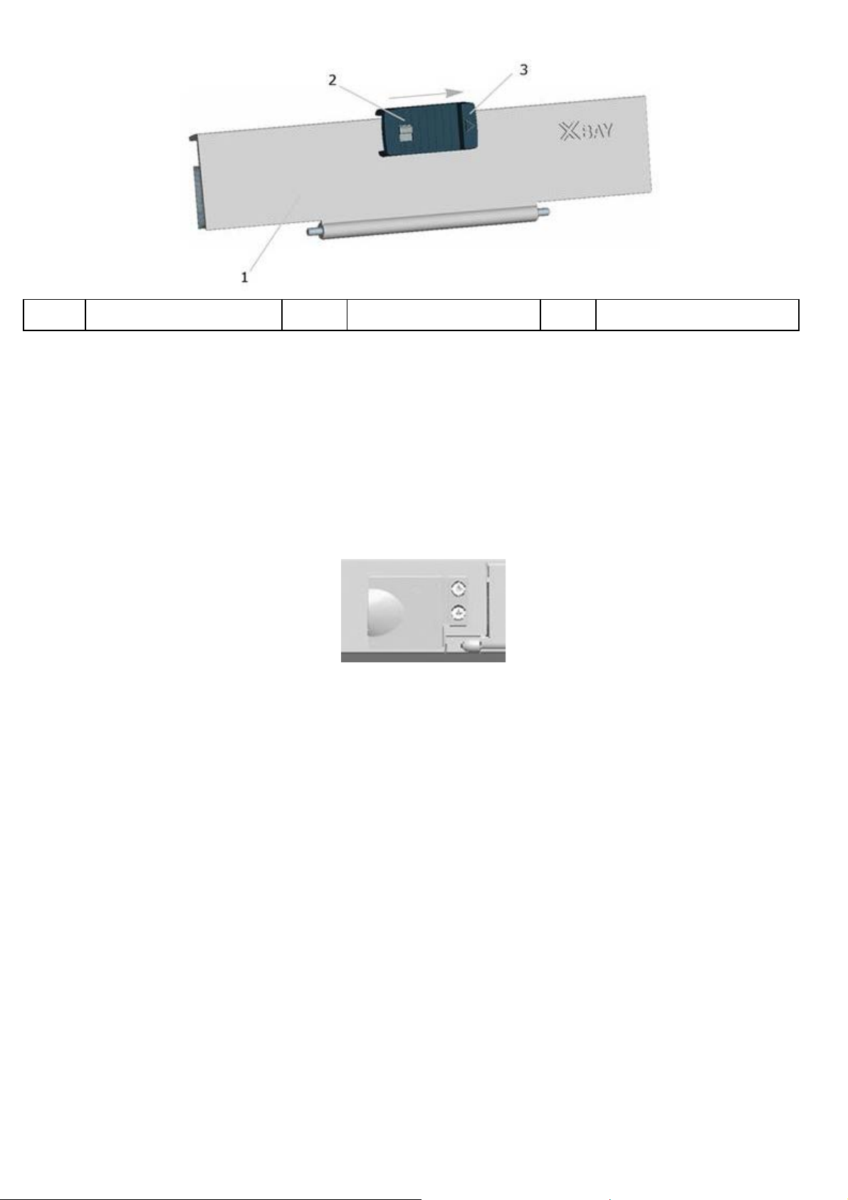
By either pressing once or pressing and holding the status button on the charge gauge on the battery, you can check:
Battery charge (check by pressing and releasing the status button)
·
· Battery health (check by pressing and holding the status button)
”.

1 Battery 2 Status button 3 Charge gauge
The battery operating time is largely determined by the number of times it is charged. After hundreds of charge and
discharge cycles, batteries lose some charge capacity — or battery health. That is, a battery can show a status of
"charged" but maintain a reduced charge capacity (health).
5.2.3.1 Check the Battery Charge
To check the battery charge, press and release the status button on the battery charge gauge to illuminate the chargelevel lights. Each light represents approximately 20 percent of the total battery charge. For example, if the battery has 80
percent of its charge remaining, four of the lights are on. If no lights appear, the battery has no charge.
5.2.3.2 Check the Battery Health
NOTE: You can check battery health in one of two ways: by using the charge gauge on the battery as described
below or by using the Battery Meter in Dell QuickSet. For information about QuickSet, right -click the icon in the
taskbar, and click Help.
To check the battery health using the charge gauge, press and hold the status button on the battery charge gauge for at
least 3 seconds. If no lights appear, the battery is in good condition, and more than 80 percent of its original charge
capacity remains. Each light represents incremental degradation. If five lights appear, less than 60 percent of the charge
capacity remains, and you should consider replacing the battery. See "Specifications" in your XFR630 with Touch Fully
Rugged Notebook User’s Guide for more information about the battery operating time.
5.3 Low-Battery Warning
NOTICE: To avoid losing or corrupting data, save your work immediately after a low-battery warning. Then
connect the computer to an electrical outlet, or install a second battery in the XBay. If the battery runs completely
out of power, hibernate mode begins automatically.
A pop-up window warns you when the battery charge is approximately 90 percent depleted. If two batteries are installed,
the low-battery warning means that the combined charge of both batteries is approximately 90 percent depleted. The
computer enters hibernate mode when the battery charge is at a critically low level.
You can change the settings for the battery alarms in QuickSet or the Power Options Properties window. See
"Configuring Power Management Settings" in the XFR630 with Touch Fully Rugged Notebook User’s Guide for information about
accessing QuickSet or the Power Options Properties window.
5.4 Charging the Battery
NOTICE: The battery temperature must be between 00C and 550C (320F and 1310F) to charge. If the battery is
not in this temperature range when a charge is attempted, the light flashes alternately green and orange. This
may happen when the battery has gotten hot from being used in your computer or in a hot environment.
Disconnect the computer from the electrical outlet and allow the computer and the battery to cool to the charging
temperature range. Then connect the computer to an electrical outlet to continue charging the battery.
NOTE: With Dell™ ExpressCharge™, when the computer is turned off, the AC adapter charges a completely
discharged battery to 80 percent in approximately 1 hour and to 100 percent in approximately 2 hours. Charge time
is longer with the computer turned on. You can leave the battery in the computer as long as you like. The battery’s
internal circuitry prevents the battery from overcharging. Battery charge times may vary dependent upon the
ambient temperature.

When you connect the computer to an electrical outlet or install a battery while the computer is connected to an electrical
outlet, the computer checks the battery charge and temperature. If necessary, the AC adapter then charges the battery
CHECK THE SOFTWARE DOCUMENTATION OR CONTACT THE SOFTWARE MANUFACTURER FOR TROUBLESHOOTING
and maintains the battery charge.
For more information about resolving problems with a battery, see "Power Problems" in your XFR630 with Touch Fully
Rugged Notebook User’s Guide.
5.5 Storing a Battery
Remove the battery when you store your computer for an extended period of time. A battery discharges during prolonged
storage. After a long storage period, recharge the battery fully (see "Charging the Battery
") before you use it.
6 Troubleshooting
6.1 Lockups and Software Problems
CAUTION: Before you begin any of the procedures in this section, follow the Safety Information in the
XFR630 with Touch Fully Rugged Notebook User’s Guide.
6.1.1 The Computer Does Not Start Up
ENSURE THAT THE AC ADAPTER IS FIRMLY CONNECTED TO THE COMPUTER AND TO THE ELECTRICAL OUTLET.
6.1.2 The Computer Stops Responding
NOTICE: You might lose data if you are unable to perform an operating system shutdown.
TURN THE COMPUTER OFF — If you are unable to get a response by pressing a key on your keyboard or moving your
mouse, press and hold the power button for at least 8 to 10 seconds until the computer turns off. Then restart your
computer.
6.1.3 A Program Stops Responding or Crashes Repeatedly
NOTE: Software usually includes installation instructions in its documentation or on a floppy disk or CD.
END THE PROGRAM —
Press <Ctrl><Alt><Del> simultaneously.
1.
Click Task Manager.
2.
Click the program that is no longer responding.
3.
Click End Task.
4.
CHECK THE SOFTWARE DOCUMENTATION — If necessary, uninstall and then reinstall the program.
6.1.4 A Program is Designed for an Earlier Microsoft® Windows
®
Operating System
RUN THE PROGRAM COMPATIBILITY WIZARD — The Program Compatibility Wizard configures a program so it runs in an
environment similar to non-Windows XP operating system environments.
Click the Start à All Programs → Accessories à Program Compatibility Wizard à Next.
1.
2. Follow the instructions on the screen.
6.1.5 A Solid Blue Screen Appears
TURN THE COMPUTER OFF — If you are unable to get a response by pressing a key on your keyboard or moving your
mouse, press and hold the power button for at least 8 to 10 seconds until the computer turns off. Then restart your
computer.
6.1.6 Other Software Problems

INFORMATION —
· Ensure that the program is compatible with the operating system installed on your computer.
·
Ensure that your computer meets the minimum hardware requirements needed to run the software. See the
software documentation for information.
· Ensure that the program is installed and configured properly.
·
Verify that the device drivers do not conflict with the program.
·
If necessary, uninstall and then reinstall the program.
BACK UP YOUR FILES IMMEDIATELY.
USE A VIRUS-SCANNING PROGRAM TO CHECK THE HARD DRIVE, FLOPPY DISKS, OR CDs.
SAVE AND CLOSE ANY OPEN FILES OR PROGRAMS AND SHUT DOWN YOUR COMPUTER THROUGH THE START MENU.
SCAN THE COMPUTER FOR SPYWARE — If you are experiencing slow computer performance, you frequently receive pop-
up advertisements, or you are having problems connecting to the Internet, your computer might be infected with
spyware. Use an anti-virus program that includes anti-spyware protection (your program may require an upgrade) to scan
the computer and remove spyware.
RUN THE DELL DIAGNOSTICS — See "Dell Diagnostics
software problem.
". If all tests run successfully, the error condition is related to a
6.2 Dell Diagnostics
CAUTION: Before you begin any of the procedures in this section, follow the Safety Information in the
XFR630 with Touch Fully Rugged Notebook User’s Guide.
6.2.1 When to Use the Dell Diagnostics
If you experience a problem with your computer, perform the checks in "Lockups and Software Problems
Diagnostics before you contact Dell for technical assistance. It is recommended that you print these procedures before you
begin.
NOTICE: The Dell Diagnostics work only on Dell™ computers.
NOTE: The Drivers and Utilities CD is optional and may not ship with your computer.
See “System Setup Program” in your XFR630 with Touch Fully Rugged Notebook User’s Guide to review your computer’s
configuration information, and ensure that the device you want to test displays in system setup and is active.
Start the Dell Diagnostics from either your hard drive or from the optional Drivers and Utilities CD.
" and run the Dell
6.2.2 Starting the Dell Diagnostics From Your Hard Drive
The Dell Diagnostics is located on a hidden diagnostic utility partition on your hard drive.
NOTE: If your computer does not display a screen image, contact Dell.
NOTE: If the computer is connected to a docking device (docked), undock it. See the documentation that came
with your docking device for instructions.
Ensure that the computer is connected to an electrical outlet that is known to be working properly.
1.
Turn on (or restart) your computer.
2.
Start the Dell Diagnostics in one of the following two ways:
3.
NOTE: If you wait too long and the operating system logo appears, continue to wait until you
see the Microsoft® Windows® desktop; then shut down your computer and try again.
When the DELL™ logo appears, press <F12> immediately. Select Diagnostics from the boot menu and press
1.
<Enter>.
NOTE: Before attempting option ‘b’, the computer must be powered down completely.

2. Press and hold the <Fn> key while powering the computer on.
NOTE: If you see a message stating that no diagnostics utility partition has been found, run the
Dell Diagnostics from the optional Drivers and Utilities CD.
The computer runs the Pre-boot System Assessment (PSA), a series of initial tests of your system board,
keyboard, hard drive, and display.
During the assessment, answer any questions that appear.
·
· If a failure is detected, the computer stops and beeps. To stop the assessment and restart the
computer, press <N>; to continue to the next test, press <Y>; to retest the component that failed,
press <R>.
If failures are detected during the Pre-boot System Assessment, write down the error code(s) and
·
contact Dell.
If the Pre-boot System Assessment completes successfully, the following message appears: “Booting Dell
Diagnostic Utility Partition. Press any key to continue”.
Press any key to start the Dell Diagnostics from the diagnostics utility partition on your hard drive.
4.
6.2.3 Starting the Dell Diagnostics From the Drivers and Utilities
CD
1. Insert the Drivers and Utilities CD.
Shut down and restart the computer.
2.
When the DELL logo appears, press <F12> immediately.
NOTE: If you wait too long and the operating system logo appears, continue to wait until you
see the Microsoft® Windows® desktop; then shut down your computer and try again.
NOTE: The next steps change the boot sequence for one time only. On the next start-up, the
computer boots according to the devices specified in the system setup program.
When the boot device list appears, highlight CD/DVD/CD-RW Drive and press <Enter>.
3.
Select the Boot from CD-ROM option from the menu that appears and press <Enter>.
4.
Type 1 to start the CD menu and press <Enter> to proceed.
5.
Select “Run the 32 Bit Dell Diagnostics” from the numbered list. If multiple versions are listed, select the
6.
version appropriate for your computer.
When the Dell Diagnostics Main Menu appears, select the test you want to run.
7.
6.2.4 Dell Diagnostics Main Menu
1. After the Dell Diagnostics loads and the Main Menu screen appears, click the button for the option you want.
NOTE: It is recommended that you select Test System to run a complete test on your
computer.
Option Function
Test Memory Run the stand-alone memory test
Test System Run the System Diagnostics
Exit Exit the Diagnostics
After you have selected the Test System option from the main menu the following menu appears:
2.
NOTE: It is recommended that you select Extended Test from the menu below to run a more
thorough check of the devices in your computer.
Option Function
Express Test Performs a quick test of devices in the system. This typically can

take 10 to 20 minutes
Extended Test Performs a thorough check of devices in the system. This typically
can take an hour or more.
Custom Test Use to test a specific device or customize the tests to be run.
Symptom Tree This option allows you to select tests based on a symptom of the
problem you are having. This option lists the most common
symptoms.
If a problem is encountered during a test, a message appears with an error code and a description of the problem.
3.
Write down the error code and problem description and contact Dell.
NOTE: The Service Tag for your computer is located on the bottom of your system. When you
contact Dell, technical support will ask for your Service Tag.
If you run a test from the Custom Test or Symptom Tree option, click the applicable tab described in the
4.
following table for more information.
Tab Function
Results Displays the results of the test and any error conditions
encountered
Errors Displays error conditions encountered, error codes, and the
problem description.
Help Describes the test and may indicate requirements for running the
test.
Configuration Displays your hardware configuration for the selected device.
The Dell Diagnostics obtains configuration information for all
devices from the system setup program, memory, and various
internal tests, and it displays the information in the device list in
the left pane of the screen. The device list may not display the
names of all the components installed on your computer or all
devices attached to your computer.
Parameters Allows you to customize the test by changing the test settings.
When the tests are completed, close the test screen to return to the Main Menu screen. To exit the Dell
5.
Diagnostics and restart the computer, close the Main Menu screen.
Remove the Dell Drivers and Utilities CD (if applicable).
6.
 Loading...