

Dell XCXR2 User Manual

Dell EMC XC XR2
Installation and Service Manual
Regulatory Model: E48S Series
Regulatory Type: E48S001

Notes, cautions, and warnings
NOTE: A NOTE indicates important information that helps you make better use of your product.
CAUTION: A CAUTION indicates either potential damage to hardware or loss of data and tells you how to avoid the
problem.
WARNING: A WARNING indicates a potential for property damage, personal injury, or death.
© 2019 Dell Inc. or its subsidiaries. All rights reserved. Dell, EMC, and other trademarks are trademarks of Dell Inc. or its subsidiaries.
Other trademarks may be trademarks of their respective owners.
2019 - 09
Rev. A00

Contents
1 Dell EMC XC XR2 overview............................................................................................................ 7
Front view of the system......................................................................................................................................................7
Left control panel view....................................................................................................................................................8
Right control panel view.................................................................................................................................................11
Drive indicator codes..................................................................................................................................................... 12
Back view of the system.....................................................................................................................................................13
NIC indicator codes........................................................................................................................................................14
Power supply unit indicator codes............................................................................................................................... 14
LCD panel..............................................................................................................................................................................16
Viewing Home screen.......................................................................................................................................................... 17
Setup menu...........................................................................................................................................................................17
View menu.............................................................................................................................................................................18
Locating the Service Tag of your system......................................................................................................................... 18
System Label Information................................................................................................................................................... 19
2 Documentation resources............................................................................................................ 21
3 Technical specifications..............................................................................................................23
System dimensions..............................................................................................................................................................23
Chassis weight.....................................................................................................................................................................24
Processor specifications.....................................................................................................................................................24
Supported Operating Systems.......................................................................................................................................... 24
PSU specifications...............................................................................................................................................................24
System battery specifications............................................................................................................................................24
Expansion bus specifications..............................................................................................................................................24
Memory specifications........................................................................................................................................................25
Storage controller specifications.......................................................................................................................................25
Drive specifications............................................................................................................................................................. 25
Drives.............................................................................................................................................................................. 25
Ports and connectors specifications.................................................................................................................................25
Common Access Card (CAC)......................................................................................................................................25
USB ports....................................................................................................................................................................... 25
eSATA port.....................................................................................................................................................................26
NIC ports........................................................................................................................................................................ 26
Serial connector.............................................................................................................................................................26
VGA ports.......................................................................................................................................................................26
Internal Dual MicroSD Module..................................................................................................................................... 26
Video specifications.............................................................................................................................................................26
Environmental specifications............................................................................................................................................. 26
Standard operating temperature................................................................................................................................. 27
Expanded operating temperature................................................................................................................................27
Particulate and gaseous contamination specifications ............................................................................................ 28
4 Initial system setup and configuration..........................................................................................30
Contents 3

Setting up your system.......................................................................................................................................................30
iDRAC configuration............................................................................................................................................................30
Options to set up iDRAC IP address........................................................................................................................... 30
Log in to iDRAC.............................................................................................................................................................. 31
Options to install the operating system.............................................................................................................................31
Methods to download firmware and drivers...............................................................................................................31
Downloading drivers and firmware...............................................................................................................................31
5 Pre-operating system management applications........................................................................... 33
Options to manage the pre-operating system applications........................................................................................... 33
System Setup.......................................................................................................................................................................33
Viewing System Setup..................................................................................................................................................33
System Setup details.....................................................................................................................................................33
System BIOS.................................................................................................................................................................. 34
iDRAC Settings utility....................................................................................................................................................49
Device Settings..............................................................................................................................................................50
Dell Lifecycle Controller......................................................................................................................................................50
Embedded system management.................................................................................................................................50
Boot Manager......................................................................................................................................................................50
Viewing Boot Manager................................................................................................................................................. 50
Boot Manager main menu............................................................................................................................................ 50
One-shot UEFI boot menu............................................................................................................................................51
System Utilities...............................................................................................................................................................51
PXE boot............................................................................................................................................................................... 51
6 Installing and removing system components.................................................................................52
Safety instructions.............................................................................................................................................................. 52
Before working inside your system................................................................................................................................... 52
After working inside your system......................................................................................................................................52
Recommended tools........................................................................................................................................................... 53
Optional front bezel.............................................................................................................................................................53
Removing the front bezel.............................................................................................................................................53
Installing the front bezel............................................................................................................................................... 53
Removing the bezel filter..............................................................................................................................................54
Installing the bezel filter................................................................................................................................................56
System cover.......................................................................................................................................................................58
Removing the system cover........................................................................................................................................ 58
Installing the system cover...........................................................................................................................................59
Inside the system.................................................................................................................................................................60
Air shroud.............................................................................................................................................................................. 61
Removing the air shroud............................................................................................................................................... 61
Installing the air shroud................................................................................................................................................. 62
Cooling fans..........................................................................................................................................................................63
Removing the cooling fan.............................................................................................................................................63
Installing the cooling fan............................................................................................................................................... 64
Front IO board..................................................................................................................................................................... 65
Removing the front IO board.......................................................................................................................................65
Installing the front IO board......................................................................................................................................... 66
Common Access Card (CAC) Or Smart Card Reader....................................................................................................67
4
Contents

Removing the Smart Card Reader.............................................................................................................................. 67
Installing the Smart Card Reader.................................................................................................................................69
Intrusion switch....................................................................................................................................................................70
Removing the intrusion switch.....................................................................................................................................70
Installing the intrusion switch........................................................................................................................................71
Drives.................................................................................................................................................................................... 72
Removing a drive blank................................................................................................................................................. 72
Installing a drive blank....................................................................................................................................................73
Removing a drive........................................................................................................................................................... 74
Installing a drive..............................................................................................................................................................74
Removing the drive from the drive carrier................................................................................................................. 75
Installing a drive into the drive carrier......................................................................................................................... 76
System memory................................................................................................................................................................... 77
System memory guidelines........................................................................................................................................... 77
General memory module installation guidelines..........................................................................................................78
Mode-specific guidelines.............................................................................................................................................. 79
Removing a memory module........................................................................................................................................82
Installing a memory module.......................................................................................................................................... 82
Processors and heat sinks..................................................................................................................................................84
Removing a processor and heat sink module.............................................................................................................84
Removing processor from the processor and heat sink module.............................................................................85
Installing the processor into a processor and heat sink module.............................................................................. 86
Installing a processor and heat sink module...............................................................................................................89
Internal PERC riser..............................................................................................................................................................90
Removing internal MiniPERC riser.............................................................................................................................. 90
Installing the internal MiniPERC riser..........................................................................................................................92
Expansion cards and expansion card risers......................................................................................................................93
Removing an expansion card riser...............................................................................................................................93
Installing an expansion card riser................................................................................................................................. 94
Removing the expansion card from the expansion card riser..................................................................................96
Installing an expansion card into the expansion card riser........................................................................................97
M.2 SSD module..................................................................................................................................................................99
Removing the M.2 SSD module...................................................................................................................................99
Installing the M.2 SSD module.....................................................................................................................................99
Optional IDSDM or vFlash module...................................................................................................................................100
Removing the optional IDSDM or vFlash card......................................................................................................... 100
Installing the IDSDM or vFlash module...................................................................................................................... 101
Removing the MicroSD card...................................................................................................................................... 102
Installing the MicroSD card.........................................................................................................................................102
LOM riser card................................................................................................................................................................... 103
Removing the LOM riser card.................................................................................................................................... 103
Installing the LOM riser card.......................................................................................................................................104
Hard drive backplane.........................................................................................................................................................105
Hard drive backplane details.......................................................................................................................................105
Removing the hard drive backplane.......................................................................................................................... 106
Installing the hard drive backplane.............................................................................................................................106
Cable routing...................................................................................................................................................................... 108
System battery...................................................................................................................................................................109
Replacing the system battery.....................................................................................................................................109
Optional internal USB memory key...................................................................................................................................110
Contents
5

Replacing the optional internal USB memory key.....................................................................................................110
Power supply units.............................................................................................................................................................. 111
Removing a power supply unit.....................................................................................................................................111
Installing a power supply unit.......................................................................................................................................112
Power interposer board..................................................................................................................................................... 113
Removing power interposer board............................................................................................................................. 113
Installing power interposer board................................................................................................................................113
Control panel....................................................................................................................................................................... 114
Removing the left control panel..................................................................................................................................114
Installing the left control panel.................................................................................................................................... 115
Removing the right control panel............................................................................................................................... 116
Installing the right control panel.................................................................................................................................. 117
System board...................................................................................................................................................................... 118
Removing the system board........................................................................................................................................118
Installing the system board......................................................................................................................................... 120
Trusted Platform Module..................................................................................................................................................122
Upgrading the Trusted Platform Module.................................................................................................................. 122
Initializing TPM for BitLocker users........................................................................................................................... 123
Initializing the TPM 1.2 for TXT users........................................................................................................................123
Initializing the TPM 2.0 for TXT users.......................................................................................................................124
901D rugged kit.................................................................................................................................................................. 124
Installing the 901D kit...................................................................................................................................................124
Installing the 901D rugged brackets...........................................................................................................................129
7 Using system diagnostics........................................................................................................... 131
Dell Embedded System Diagnostics................................................................................................................................. 131
Running the Embedded System Diagnostics from Boot Manager.........................................................................131
Running the Embedded System Diagnostics from the Dell Lifecycle Controller..................................................131
System diagnostic controls.........................................................................................................................................132
8 Jumpers and connectors ...........................................................................................................133
System board jumpers and connectors...........................................................................................................................133
System board jumper settings..........................................................................................................................................134
Disabling forgotten password...........................................................................................................................................135
9 Getting help............................................................................................................................. 136
Contacting Dell...................................................................................................................................................................136
Accessing system information by using QRL................................................................................................................. 136
Quick Resource Locator for XC XR2.........................................................................................................................137
Receiving automated support with SupportAssist ................................................................................................. 137
Recycling or End-of-Life service information........................................................................................................... 137
6
Contents
Dell EMC XC XR2 overview
The XC XR2 is a 1U, dual socket rack system with 8 x 2.5 inch drives system and supports up to:
• Two Intel Xeon Processor Scalable Family processors
• 16 DIMM slots
• Integrated M.2 module
• Two redundant power supply units (PSU)
NOTE: All instances of SAS, SATA hard drives and SSDs are referred to as drives in this document, unless specified
otherwise.
Topics:
• Front view of the system
• Back view of the system
• LCD panel
• Viewing Home screen
• Setup menu
• View menu
• Locating the Service Tag of your system
• System Label Information
1
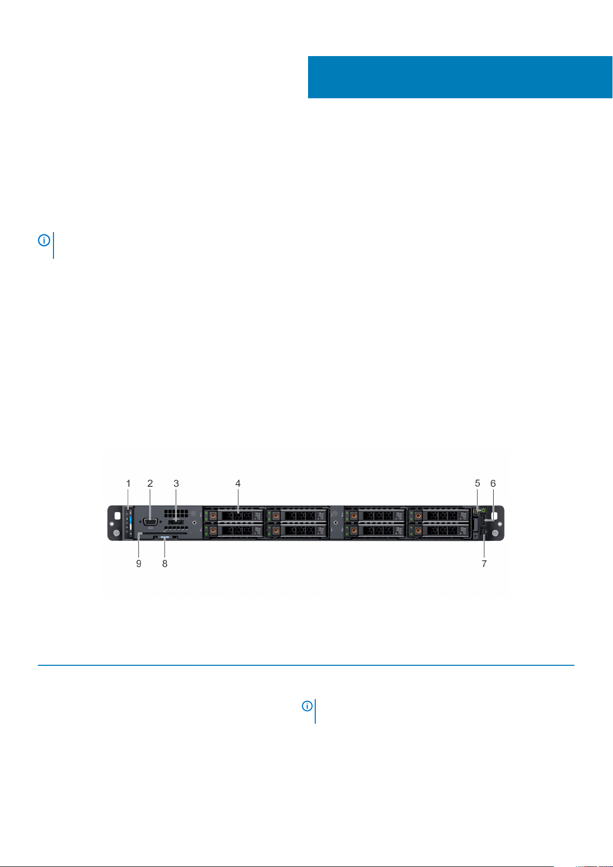
Front view of the system
The front view of the system displays the features available on the front of the system.
Figure 1. Front view of the system
Table 1. Features available on the front of the system
Item Ports, panels, and slots Icon Description
1 Left control panel N/A
Contains the system health and system ID, status LED, and the
iDRAC Quick Sync 2 (wireless) indicator.
NOTE: The iDRAC Quick Sync 2 indicator is available only
on certain configurations.
• Status LED: Enables you to identify any failed hardware
components. There are up to five status LEDs and an overall
system health LED (Chassis health and system ID) bar. For more
information, see the
LED indicators section.
Dell EMC XC XR2 overview 7
Item Ports, panels, and slots Icon Description
• Quick Sync 2 (wireless): Indicates a Quick Sync enabled system.
The Quick Sync feature is optional. This feature allows
management of the system by using mobile devices. This feature
aggregates hardware or firmware inventory and various system
level diagnostic and error information that can be used in
troubleshooting the system. For more information, see the
Integrated Dell Remote Access Controller User’s Guide at
www.dell.com/idracmanuals.
2 VGA port Use the VGA port to connect a display to the system. For more
information about the supported VGA port, see the Technical
specifications section.
3 eSATA port The port enables you to connect external storage devices to the
system.
4 Drive slots N/A
Enable you to install drives that are supported on your system. For
more information about drives, see the Technical specifications
section.
5 Power button
6 USB port The USB port is 4-pin, 2.0-compliant. The port enables you to
7 iDRAC Direct port
8 Information tag N/A
9 Common Access Card
(CAC) Or Smart Card
Reader
N/A Allows for an additional form of authentication for data encryption.
Indicates if the system is turned on or off. Press the power button to
manually turn on or off the system.
NOTE: Press the power button to gracefully shut down an
ACPI-compliant operating system.
connect USB devices to the system.
The iDRAC Direct port is micro USB 2.0-compliant. This port enables
you to access the iDRAC Direct features. For more information, see
the Integrated Dell Remote Access Controller User's Guide at
www.dell.com/poweredgemanuals.
The Information tag is a slide-out label panel that contains system
information such as Service Tag, NIC, MAC address, and so on. If you
have opted for the secure default access to iDRAC, the Information
tag also contains the iDRAC secure default password.
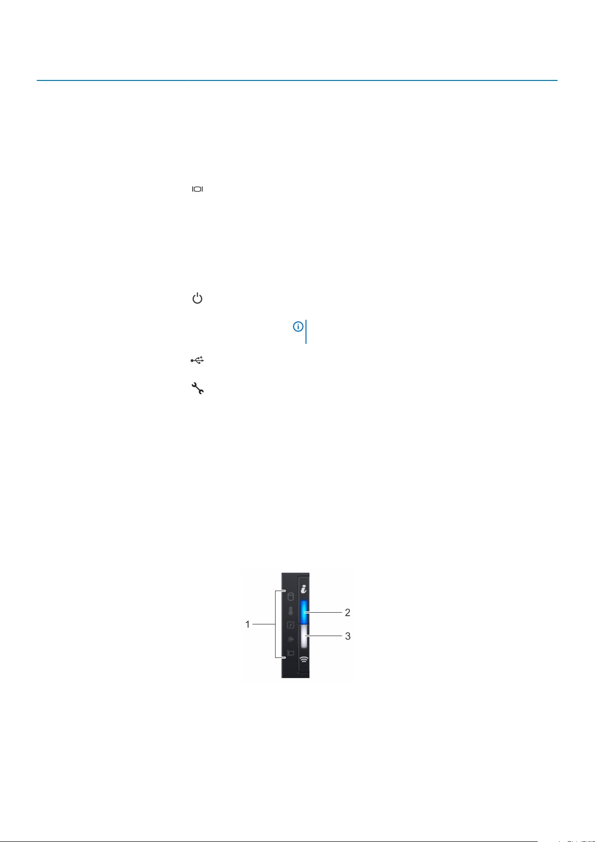
Left control panel view
Figure 2. Left control panel with optional iDRAC Quick Sync 2.0 indicator
8
Dell EMC XC XR2 overview
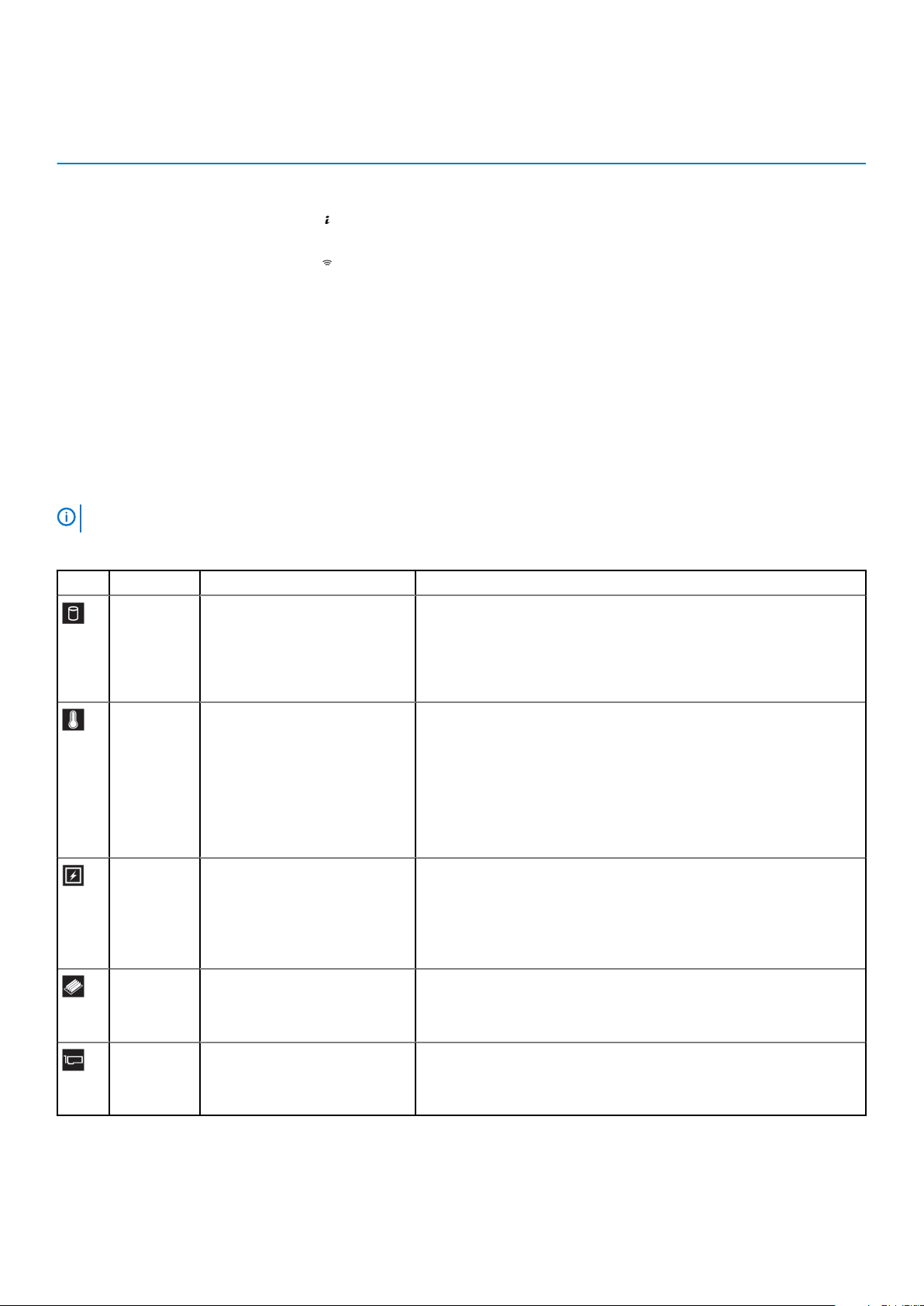
Table 2. Left control panel
Item Indicator, button, or
connector
1 Status LED indicators N/A Indicate the status of the system. For more information, see the
2 System health and system
ID indicator
3 iDRAC Quick Sync 2
wireless indicator (optional)
Icon Description
Status LED indicators section.
Indicates the system health.
Indicates if the iDRAC Quick Sync 2 wireless option is activated. The
Quick Sync 2 feature allows management of the system using mobile
devices. This feature aggregates hardware/firmware inventory and
various system level diagnostic/error information that can be used in
troubleshooting the system. You can access system inventory, Dell
Lifecycle Controller logs or system logs, system health status, and
also configure iDRAC, BIOS, and networking parameters. You can
also launch the virtual Keyboard, Video, and Mouse (KVM) viewer
and virtual Kernel based Virtual Machine (KVM), on a supported
mobile device. For more information, see the Integrated Dell Remote
Access Controller User's Guide at
www.dell.com/poweredgemanuals
Status LED indicators
NOTE:
The indicators display solid amber if any error occurs.
Table 3. Status LED indicators and descriptions
Icon Description Condition Corrective action
Drive
indicator
The indicator turns solid amber if
there is a drive error.
• Check the System Event Log to determine if the drive has an error.
• Run the appropriate Online Diagnostics test. Restart the system and
run embedded diagnostics (ePSA).
• If the drives are configured in a RAID array, restart the system, and
enter the host adapter configuration utility program.
Temperature
indicator
Electrical
indicator
Memory
indicator
PCIe
indicator
The indicator turns solid amber if
the system experiences a thermal
error (for example, the ambient
temperature is out of range or
there is a fan failure).
The indicator turns solid amber if
the system experiences an
electrical error (for example,
voltage out of range, or a failed
power supply unit (PSU) or
voltage regulator).
The indicator turns solid amber if a
memory error occurs.
The indicator turns solid amber if a
PCIe card experiences an error.
Ensure that none of the following conditions exist:
• A cooling fan has been removed or has failed.
• System cover, air shroud, memory module blank, or back filler bracket
is removed.
• Ambient temperature is too high.
• External airflow is obstructed.
If the problem persists, see Getting help.
Check the System Event Log or system messages for the specific issue. If
it is due to a problem with the PSU, check the LED on the PSU. Reseat the
PSU.
If the problem persists, see Getting help.
Check the System Event Log or system messages for the location of the
failed memory. Reseat the memory module.
If the problem persists, see Getting help.
Restart the system. Update any required drivers for the PCIe card.
Reinstall the card.
If the problem persists, see Getting help.
Dell EMC XC XR2 overview 9

System health and system ID indicator codes
The system health and system ID indicator is located on the left control panel of your system.
Figure 3. System health and system ID indicators
Table 4. System health and system ID indicator codes
System health and system ID indicator code Condition
Solid blue Indicates that the system is turned on, system is healthy, and system
ID mode is not active. Press the system health and system ID button
to switch to system ID mode.
Blinking blue Indicates that the system ID mode is active. Press the system health
and system ID button to switch to system health mode.
Solid amber Indicates that the system is in fail-safe mode. If the problem persists,
see the Getting help section.
Blinking amber Indicates that the system is experiencing a fault. Check the System
Event Log or the LCD panel, if available on the bezel, for specific error
messages.
For more information about error messages, see the Event and Error
Message Reference Guide for 14th Generation Dell EMC PowerEdge
Servers at www.dell.com/qrl.
iDRAC Quick Sync 2 indicator codes
iDRAC Quick Sync 2 module (optional) is located on the left control panel of your system.
Figure 4. iDRAC Quick Sync 2 indicators
Table 5. iDRAC Quick Sync 2 indicators and descriptions
iDRAC Quick Sync 2 indicator
code
Off (default state) Indicates that the iDRAC Quick Sync 2
Solid white Indicates that iDRAC Quick Sync 2 is ready
Blinks white rapidly Indicates data transfer activity.
Blinks white slowly Indicates that firmware update is in
Condition Corrective action
If the LED fails to turn on, reseat the left control
feature is turned off. Press the iDRAC
Quick Sync 2 button to turn on the iDRAC
Quick Sync 2 feature.
to communicate. Press the iDRAC Quick
Sync 2 button to turn off.
progress.
panel flex cable and check. If the problem persists,
see the Getting help section.
If the LED fails to turn off, restart the system. If the
problem persists, see the Getting help section.
If the indicator continues to blink indefinitely, see the
Getting help section.
If the indicator continues to blink indefinitely, see the
Getting help section.
Blinks white five times rapidly and
then turns off
10 Dell EMC XC XR2 overview
Indicates that the iDRAC Quick Sync 2
feature is disabled.
Check if iDRAC Quick Sync 2 feature is configured to
be disabled by iDRAC. If the problem persists, see the
Getting help section. For more information, see
iDRAC Quick Sync 2 indicator
code
Solid amber Indicates that the system is in fail-safe
Blinking amber Indicates that the iDRAC Quick Sync 2
Condition Corrective action
mode.
hardware is not responding properly.
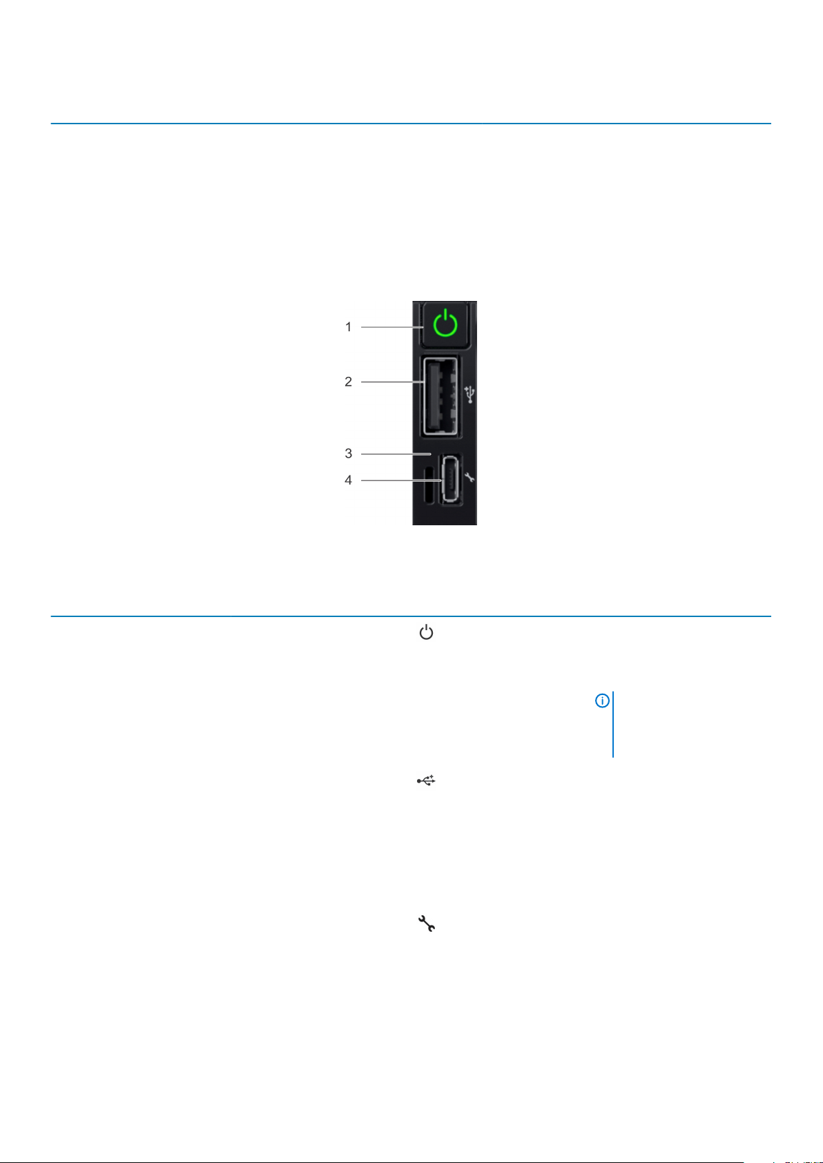
Right control panel view
Integrated Dell Remote Access Controller User's
Guide at www.dell.com/idracmanuals .
Restart the system. If the problem persists, see the
Getting help section.
Restart the system. If the problem persists, see the
Getting help section.
Figure 5. Right control panel
Table 6. Right control panel
Item Indicator or button Icon Description
1 Power button
2 USB port
3 iDRAC Direct LED N/A The iDRAC Direct LED indicator
4 iDRAC Direct port (Micro-AB
USB)
Indicates if the system is turned
on or off. Press the power
button to manually turn on or off
the system.
NOTE: Press the power
button to gracefully shut
down an ACPI-compliant
operating system.
The USB ports are 4-pin, 2.0compliant. This port enables you
to connect USB devices to the
system.
lights up to indicate that the
iDRAC Direct port is actively
connected to a device.
The iDRAC Direct (Micro-AB
USB) port enables you to access
the iDRAC Direct (Micro-AB)
features. For more information,
see the iDRAC User’s Guide at
www.dell.com/idracmanuals.
Dell EMC XC XR2 overview 11
Drive indicator codes
The LEDs on the drive carrier indicates the state of each drive. Each drive carrier in your system has two LEDs: an activity LED (green)
and a status LED (bicolor, green or amber). The activity LED flashes whenever the drive is accessed.
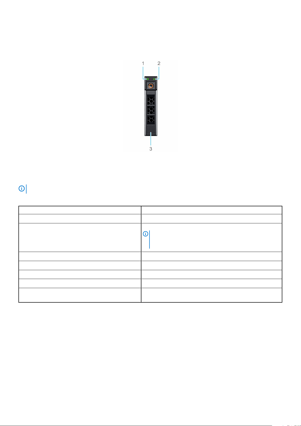
Figure 6. Drive indicators on the drive and the mid drive tray backplane
1. Drive activity LED indicator
2. Drive status LED indicator
3. Drive capacity label
If the drive is in the Advanced Host Controller Interface (AHCI) mode, the status LED indicator does not turn on.
NOTE:
Table 7. Drive indicator codes
Drive status indicator code Condition
Flashes green twice per second Identifying drive or preparing for removal.
Off Drive ready for removal.
NOTE: The drive status indicator remains off until all drives
are initialized after the system is turned on. Drives are not
ready for removal during this time.
Flashes green, amber, and then turns off Predicted drive failure.
Flashes amber four times per second Drive failed.
Flashes green slowly Drive rebuilding.
Solid green Drive online.
Flashes green for three seconds, amber for three seconds,
and then turns off after six seconds
Rebuild stopped.
12 Dell EMC XC XR2 overview
Back view of the system
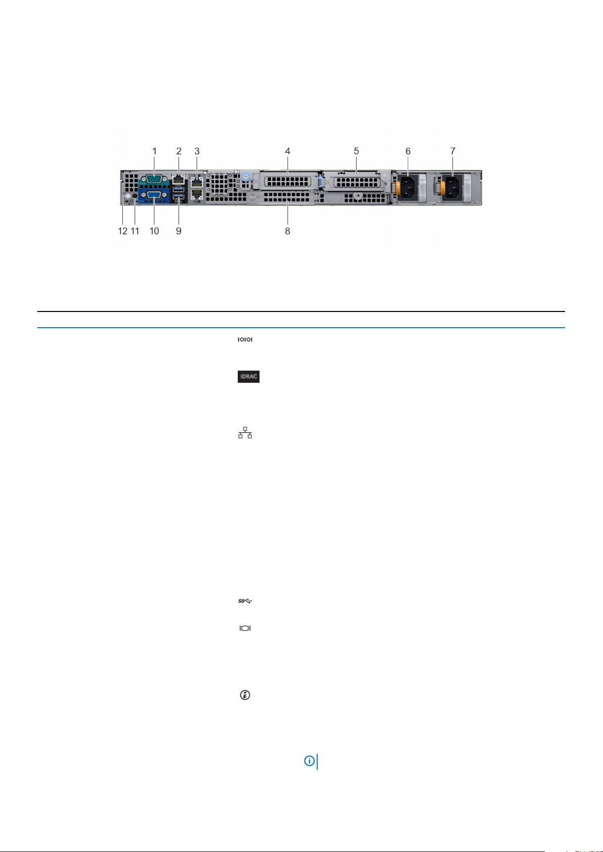
The back view of the system displays the features available on the back of the system.
Figure 7. Back view of the system
Table 8. Back panel features of XC XR2
Item Features Icon Description
1 Serial port Use the serial port to connect a serial device to the system. For
more information about the supported serial port, see the Technical
specifications section.
2 iDRAC9 Enterprise port
Use the iDRAC9 dedicated network port to securely access the
embedded iDRAC on a separate management network, see the
Integrated Dell Remote Access Controller User's Guide at
www.dell.com/idracmanuals.
3 Ethernet ports (2) Use the Ethernet ports to connect Local Area Networks (LANs) to
the system. For more information about the supported Ethernet
ports, see the Technical specifications section.
4 Low profile riser right slot N/A Use the card slot to connect half-height PCIe expansion card on
low profile riser.
5 Low profile riser left slot N/A Use the card slot to connect half-height PCIe expansion card on
low profile riser.
6 Power supply unit (PSU) N/A For more information about the PSU configurations, see the
Technical specifications section.
7 Power supply unit (PSU) N/A For more information about the PSU configurations, see the
Technical specifications section.
8 LOM riser slot N/A Use the LOM riser slot to connect additional NIC.
9 USB 3.0 port (2) Use the USB 3.0 port to connect USB devices to the system.
These ports are 4-pin, USB 3.0-compliant.
10 VGA port Use the VGA port to connect a display to the system. For more
information about the supported VGA port, see the Technical
specifications section.
11 System status indicator cable
port
12 System identification button Press the system ID button:
N/A Enables you to connect the status indicator cable and view system
status when the CMA is installed.
• To locate a particular system within a rack.
• To turn the system ID on or off.
To reset iDRAC, press and hold the button for more than 15
seconds.
NOTE:
Dell EMC XC XR2 overview 13
Item Features Icon Description
• To reset iDRAC using system ID, ensure that the
system ID button is enabled in the iDRAC setup.
• If the system stops responding during POST, press
and hold the system ID button (for more than five
seconds) to enter the BIOS progress mode.
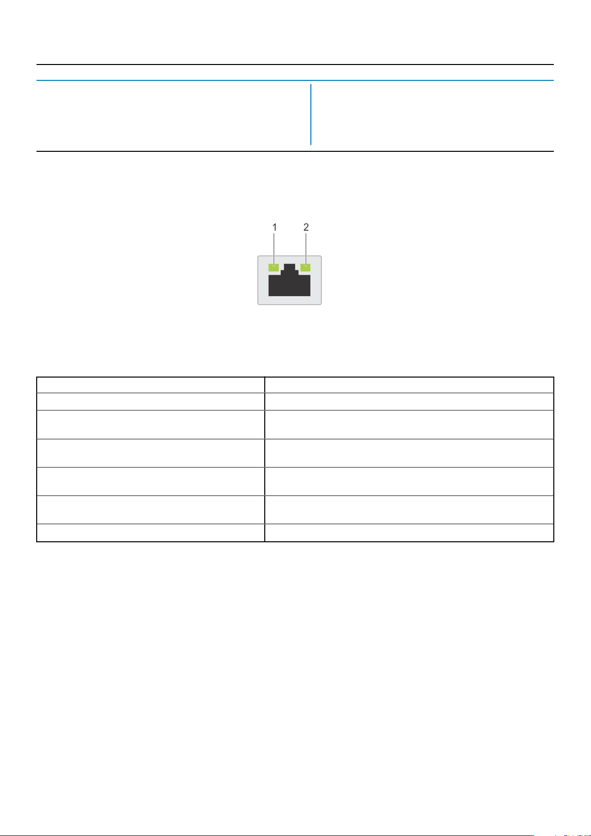
NIC indicator codes
Each NIC on the back of the system has indicators that provide information about the activity and link status. The activity LED indicator
indicates if data is flowing through the NIC, and the link LED indicator indicates the speed of the connected network.
Figure 8. NIC indicator codes
1. Link LED indicator
2. Activity LED indicator
Table 9. NIC indicator codes
Status Condition
Link and activity indicators are off. The NIC is not connected to the network.
Link indicator is green, and activity indicator is blinking
green.
Link indicator is amber, and activity indicator is blinking
green.
Link indicator is green, and activity indicator is off. The NIC is connected to a valid network at its maximum port speed, and
Link indicator is amber, and activity indicator is off. The NIC is connected to a valid network at less than its maximum port
Link indicator is blinking green, and activity is off. NIC identify is enabled through the NIC configuration utility.
The NIC is connected to a valid network at its maximum port speed, and
data is being sent or received.
The NIC is connected to a valid network at less than its maximum port
speed, and data is being sent or received.
data is not being sent or received.
speed, and data is not being sent or received.
Power supply unit indicator codes
AC power supply units (PSUs) have an illuminated translucent handle that serves as an indicator.
The indicator shows whether power is present or if a power fault has occurred.
14
Dell EMC XC XR2 overview

Figure 9. AC PSU status indicator
1. AC PSU status indicator/handle
Table 10. AC PSU status indicator codes
Power indicator codes Condition
Green A valid power source is connected to the PSU and the PSU is operational.
Blinking amber Indicates a problem with the PSU.
Not illuminated Power is not connected to the PSU.
Blinking green When the firmware of the PSU is being updated, the PSU handle blinks green.
CAUTION: Do not disconnect the power cord or unplug the PSU when updating firmware. If
firmware update is interrupted, the PSUs do not function.
Blinking green and turns off When hot-plugging a PSU, the PSU handle blinks green five times at a rate of 4 Hz and turns off. This
indicates a PSU mismatch with respect to efficiency, feature set, health status, or supported voltage.
CAUTION: If two PSUs are installed, both the PSUs must have the same type of label; for
example, Extended Power Performance (EPP) label. Mixing PSUs from previous generations
of XC XR2 servers is not supported, even if the PSUs have the same power rating. This
results in a PSU mismatch condition or failure to turn the system on.
CAUTION: When correcting a PSU mismatch, replace only the PSU with the blinking
indicator. Swapping the PSU to make a matched pair can result in an error condition and
unexpected system shutdown. To change from a high output configuration to a low output
configuration or vice versa, you must turn off the system.
CAUTION: AC PSUs support both 240 V and 120 V input voltages with the exception of
Titanium PSUs, which support only 240 V. When two identical PSUs receive different input
voltages, they can output different wattages, and trigger a mismatch.
CAUTION: If two PSUs are used, they must be of the same type, and have the same
maximum output power.
CAUTION: Combining AC and DC PSUs is not supported and triggers a mismatch.
Dell EMC XC XR2 overview 15
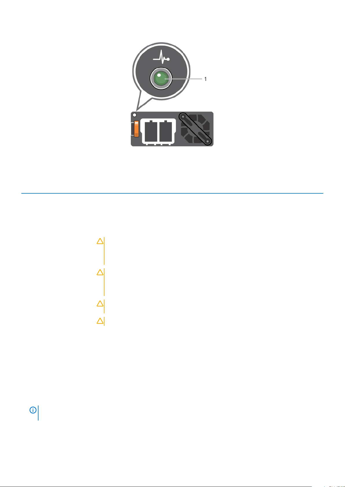
Figure 10. DC PSU status indicator
1. DC PSU status indicator
Table 11. DC PSU status indicator codes
Power indicator codes Condition
Green A valid power source is connected to the PSU and the PSU is operational.
Blinking amber Indicates a problem with the PSU.
Not illuminated Power is not connected to the PSU.
Blinking green When hot-plugging a PSU, the PSU indicator blinks green. This indicates that there is a PSU mismatch
with respect to efficiency, feature set, health status, or supported voltage.
CAUTION: If two PSUs are installed, both the PSUs must have the same type of label;
for example, Extended Power Performance (EPP) label. Mixing PSUs from previous
generations of XC XR2 servers is not supported, even if the PSUs have the same power
rating. This results in a PSU mismatch condition or failure to turn the system on.
CAUTION: When correcting a PSU mismatch, replace only the PSU with the blinking
indicator. Swapping the PSU to make a matched pair can result in an error condition and
unexpected system shutdown. To change from a High Output configuration to a Low
Output configuration or vice versa, you must turn off the system.
CAUTION: If two PSUs are used, they must be of the same type and have the same
maximum output power.
CAUTION: Combining AC and DC PSUs is not supported and triggers a mismatch.
LCD panel
The LCD panel provides system information, status, and error messages to indicate if the system is functioning correctly or requires
attention. The LCD panel can also be used to configure or view the system’s iDRAC IP address. For information about the event and error
messages generated by the system firmware and agents that monitor system components, see the Error Code Lookup page at
qrl.dell.com.
The statuses and conditions of the LCD panel are outlined here:
• The LCD backlight is white during normal operating conditions.
• When the system needs attention, the LCD backlight turns amber, and displays an error code followed by descriptive text.
NOTE:
whether the system is turned on or off.
• When the system turns off and there are no errors, LCD enters the standby mode after five minutes of inactivity. Press any button on
the LCD to turn it on.
• If the LCD panel stops responding, remove the bezel and reinstall it.
16
If the system is connected to a power source and an error is detected, the LCD turns amber regardless of
Dell EMC XC XR2 overview
If the problem persists, see Getting help.
• The LCD backlight remains off if LCD messaging is turned off using the iDRAC utility, the LCD panel, or other tools.
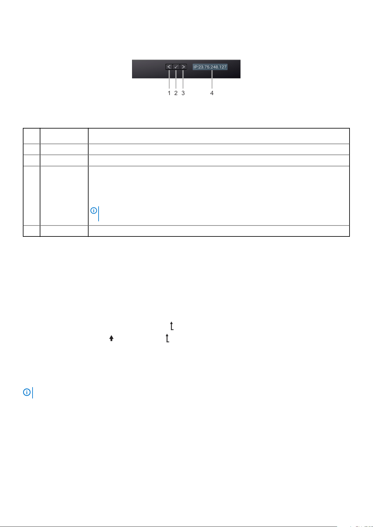
Figure 11. LCD panel features
Table 12. LCD panel features
Item Button or
display
1 Left Moves the cursor back in one-step increments.
2 Select Selects the menu item highlighted by the cursor.
3 Right Moves the cursor forward in one-step increments.
4 LCD display Displays system information, status, and error messages or iDRAC IP address.
Description
During message scrolling:
• Press and hold the right button to increase scrolling speed.
• Release the button to stop.
NOTE: The display stops scrolling when the button is released. After 45 seconds of inactivity,
the display starts scrolling.
Viewing Home screen
The Home screen displays user-configurable information about the system. This screen is displayed during normal system operation when
there are no status messages or errors. When the system turns off and there are no errors, LCD enters the standby mode after five
minutes of inactivity. Press any button on the LCD to turn it on.
Steps
1. To view the Home screen, press one of the three navigation buttons (Select, Left, or Right).
2. To navigate to the Home screen from another menu, complete the following steps:
a) Press and hold the navigation button till the up arrow is displayed.
b) Navigate to the Home icon using the up arrow .
c) Select the Home icon.
d) On the Home screen, press the Select button to enter the main menu.
Setup menu
When you select an option in the Setup menu, you must confirm the option before proceeding to the next action.
NOTE:
Option Description
iDRAC Select DHCP or Static IP to configure the network mode. If Static IP is selected, the available fields are IP,
Subnet (Sub), and Gateway (Gtw). Select Setup DNS to enable DNS and to view domain addresses. Two
separate DNS entries are available.
Set error Select SEL to view LCD error messages in a format that matches the IPMI description in the SEL. This enables
you to match an LCD message with an SEL entry.
Dell EMC XC XR2 overview 17
Option Description
Select Simple to view LCD error messages in a simplified user-friendly description. For information about the
event and error messages generated by the system firmware and agents that monitor system components, see
the Error Code Lookup page at qrl.dell.com
Set home Select the default information to be displayed on the Home screen. See View menu section for the options and
option items that can be set as the default on the Home screen.
View menu
NOTE: When you select an option in the View menu, you must confirm the option before proceeding to the next action.
Option Description
iDRAC IP Displays the IPv4 or IPv6 addresses for iDRAC9. Addresses include DNS (Primary and Secondary), Gateway,
IP, and Subnet (IPv6 does not have Subnet).
MAC Displays the MAC addresses for iDRAC, iSCSI, or Network devices.
Name Displays the name of the Host, Model, or User String for the system.
Number Displays the Asset tag or the Service tag for the system.
Power Displays the power output of the system in BTU/hr or Watts. The display format can be configured in the Set
home submenu of the Setup menu.
Temperature Displays the temperature of the system in Celsius or Fahrenheit. The display format can be configured in the Set
home submenu of the Setup menu.
Locating the Service Tag of your system
You can identify your system using the unique Express Service Code and Service Tag. Pull out the information tag in front of the system
to view the Express Service Code and Service Tag. Alternatively, the information may be on a sticker on the chassis of the system. The
mini Enterprise Service Tag (EST) is found on the back of the system. This information is used by Dell to route support calls to the
appropriate personnel.
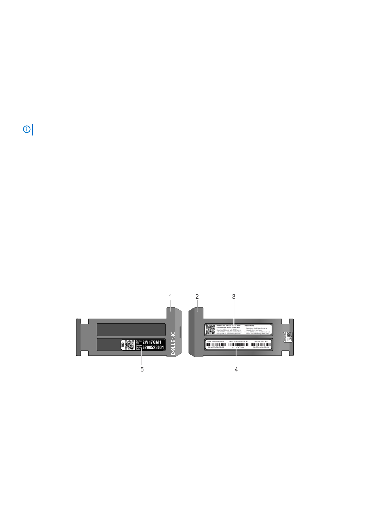
Figure 12. Locating Service Tag of your system
1.
information tag (front view) 2. information tag (back view)
3. OpenManage Mobile (OMM) label 4. iDRAC MAC address and iDRAC secure password label
5. Service Tag
18 Dell EMC XC XR2 overview

System Label Information
Figure 13. Service and Memory Information Label
Figure 14. Smart Card Reader label
Dell EMC XC XR2 overview
19
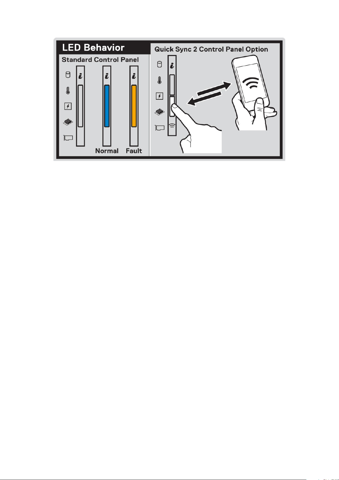
Figure 15. LED behavior and Quick sync 2 control panel label
20 Dell EMC XC XR2 overview

Documentation resources
This section provides information about the documentation resources for your system.
To view the document that is listed in the documentation resources table:
• From the Dell EMC support site:
1. Click the documentation link that is provided in the Location column in the table.
2. Click the required product or product version.
NOTE:
3. On the Product Support page, click Manuals & documents.
• Using search engines:
• Type the name and version of the document in the search box.
Table 13. Additional documentation resources for your system
Task Document Location
Setting up your system
To locate the product name and model, see the front of your system.
For more information about installing and securing
the system into a rack, see the Rail Installation
Guide included with your rack solution.
For information about setting up your system, see
the Getting Started Guide document that is
shipped with your system.
www.dell.com/poweredgemanuals
2
Configuring your system For information about the iDRAC features,
configuring and logging in to iDRAC, and managing
your system remotely, see the Integrated Dell
Remote Access Controller User's Guide.
For information about understanding Remote
Access Controller Admin (RACADM)
subcommands and supported RACADM
interfaces, see the RACADM CLI Guide for iDRAC.
For information about Redfish and its protocol,
supported schema, and Redfish Eventing
implemented in iDRAC, see the Redfish API Guide.
For information about iDRAC property database
group and object descriptions, see the Attribute
Registry Guide.
For information about earlier versions of the
iDRAC documents.
To identify the version of iDRAC available on your
system, on the iDRAC web interface, click
About.
For information about installing the operating
system, see the op erating system documentation.
For information about updating drivers and
firmware, see the Methods to download firmware
and drivers section in this document.
www.dell.com/poweredgemanuals
www.dell.com/idracmanuals
? >
www.dell.com/operatingsystemmanuals
www.dell.com/support/drivers
Managing your system For information about systems management
software offered by Dell, see the Dell
www.dell.com/poweredgemanuals
Documentation resources 21

Task Document Location
OpenManage Systems Management Overview
Guide.
For information about installing and using Dell
SupportAssist, see the Dell EMC SupportAssist
Enterprise User’s Guide.
For information about partner programs enterprise
systems management, see the OpenManage
Connections Enterprise Systems Management
documents.
Working with the Dell
PowerEdge RAID controllers
Understanding event and error
messages
Troubleshooting your system For information about identifying and
For information about understanding the features
of the BOSS card and deploying the cards, see the
Storage controller documentation.
For information about the event and error
messages generated by the system firmware and
agents that monitor system components, see the
Error Code Lookup.
troubleshooting the PowerEdge server issues, see
the Server Troubleshooting Guide.
www.dell.com/serviceabilitytools
www.dell.com/openmanagemanuals
www.dell.com/storagecontrollermanuals
www.dell.com/qrl
www.dell.com/poweredgemanuals
22 Documentation resources
Technical specifications
The technical and environmental specifications of your system are outlined in this section.
Topics:
• System dimensions
• Chassis weight
• Processor specifications
• Supported Operating Systems
• PSU specifications
• System battery specifications
• Expansion bus specifications
• Memory specifications
• Storage controller specifications
• Drive specifications
• Ports and connectors specifications
• Video specifications
• Environmental specifications
System dimensions
3
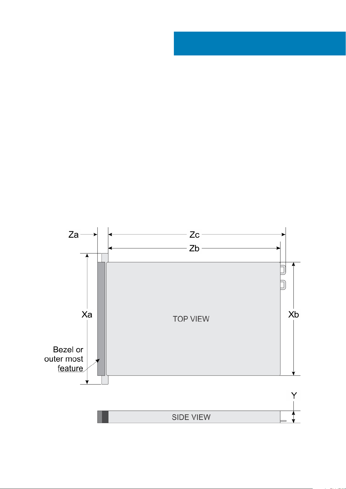
Figure 16. Dimensions of the XC XR2 system
Technical specifications 23

Table 14. Dimensions of the XC XR2 system
Xa Xb Y Za (with bezel) Za (without
482.6 mm (19
inches)
434.0 mm (17.08
inches)
42.8 mm (1.68
inches)
63.15 mm (2.46
inches)
bezel)
33.9 mm (1.32
inches)
Zb Zc
514.35 mm
(20.06 inches)
Chassis weight
Table 15. Chassis weight
System Maximum weight (with all drives/SSDs)
8 x 2.5 inch drive system 13.00 Kg (28 lb)
Processor specifications
The XC XR2 system supports up to two Intel Xeon Processor Scalable Family processors.
Supported Operating Systems
For information about supported operating systems, see the Support Matrix at www.dell.com/xcseriesmanuals.
PSU specifications
547.4 mm (21.35
inches)
The XC XR2 system supports the following AC power supply units (PSU).
Table 16. PSU specifications
PSU Class Heat dissipation
(maximum)
550 W AC Platinum 2891 BTU/hr 50/60 Hz 115–230 V AC, autoranging
NOTE: Heat dissipation is calculated using the PSU wattage rating.
NOTE: This system is also designed to connect to the IT power systems with a phase-to-phase voltage not exceeding
230 V.
Frequency Voltage
System battery specifications
The XC XR2 system supports CR 2032 3.0-V lithium coin cell system battery.
Expansion bus specifications
The XC XR2 system supports PCI express (PCIe) generation three expansion cards, which must be installed on the system board using
expansion card risers. The XR2 system supports two types of expansion card risers.
Table 17. Expansion card riser configurations
Expansion card riser PCIe slots on the riser Processor
connection
Riser 1 Slot 1 Processor 1 Full Height Half Length x16
Riser 2 Slot 1 Processor 1 Low Profile Half Length x16
Slot 2 Processor 2 Low Profile Half Length x16
Height Length Slot width
24 Technical specifications

Memory specifications
The XC XR2 system supports 16 DDR4 registered DIMM (RDIMMs) slots. Supported memory bus frequencies are 2666 MT/s, 2400
MT/s, 2133 MT/s, and 1866 MT/s.
Table 18. Memory specifications
DIMM
type
RDIMM Dual rank 16 GB 16 GB 160 GB 32 GB 256 GB
RDIMM Dual rank 32 GB 32 GB 320 GB 64 GB 512 GB
LRDIMM Quad rank 64 GB 64 GB 640 GB 128 GB 1024 GB
DIMM rank
DIMM
capacity
Minimum RAM Maximum RAM Minimum RAM Maximum RAM
Single processor Dual processors
Storage controller specifications
The Dell EMC XC XR2 system supports:
• Internal controllers: PowerEdge Expandable RAID Controller (PERC) HBA330
• HBAs (non-RAID): 12 Gbps SAS HBA
• Boot Optimized Storage Subsystem (BOSS): HWRAID 2 x M.2 SSDs 120GB, 240 GB with 6Gbps
• x8 connector using PCIe gen 2.0 x2 lanes, available only in the low-profile and half-height form factor
Drive specifications
Drives
The XC XR2 system supports:
• Up to 8 x 2.5 inch drives with drive adapter, internal, hot swappable SATA, SAS SSDs, and SAS HDDs
Ports and connectors specifications
Common Access Card (CAC)
The integrated Common Access Card (CAC) reader or Smart card reader allows for an additional form of authentication for data
encryption. The XC XR2 system supports one CAC on the front panel.
USB ports
The XC XR2 system supports:
• USB 2.0-compliant port on the front panel
• USB 3.0-compliant port on the back panel
The following table provides more information about the USB specifications:
Table 19. USB specifications
Front panel Back panel Internal USB
• One USB 2.0-compliant port
• One iDRAC Direct (Micro-AB USB)
port
• Two USB 3.0-compliant port • One internal USB 2.0 port on the FIO board
Technical specifications 25

eSATA port
The XC XR2 system supports one eSATA port on the front panel of the system.
NIC ports
The XC XR2 system supports two Network Interface Controller (NIC) ports on the back panel, which have two 1 Gbps configuration.
Serial connector
The serial connector connects a serial device to the system. The XC XR2 system supports one serial connector on the back panel, which
is a 9-pin connector, Data Terminal Equipment (DTE), 16550-compliant.
VGA ports
The Video Graphic Array (VGA) port enables you to connect the system to a VGA display. The XC XR2 system supports two 15-pin VGA
ports on the front and back panels .
Internal Dual MicroSD Module
The XC XR2 system supports two optional flash memory card slots with an internal dual MicroSD module.
One card slot is dedicated for redundancy.
NOTE:
Video specifications
The XC XR2 system supports Matrox G200eR2 graphics card with 16 MB capacity.
Table 20. Supported video resolution options
Resolution Refresh rate (Hz) Color depth (bits)
640 x 480 60, 70 8, 16, 32
800 x 600 60, 75, 85 8, 16, 32
1024 x 768 60, 75, 85 8, 16, 32
1152 x 864 60, 75, 85 8, 16, 32
1280 x 1024 60, 75 8, 16, 32
1440 x 900 60 8, 16, 32
Environmental specifications
For additional information about environmental certifications, please refer to the Product Environmental
NOTE:
Datasheet located with the Manuals & Documents on www.dell.com/poweredgemanuals
Table 21. Temperature specifications
Temperature Specifications
Storage –40°C to 70°C (–40°F to 158°F) per Mil-Std 810G Method 501.5, Proc 1
Continuous operation (for altitude less than 950 m or 3117
ft)
Fresh air For information about fresh air, see Expanded operating temperature
Excursion temperature 55°C per Mil-Std 810G
5°C to 45°C (41°F to 104°F), with no direct sunlight on the equipment
section.
26 Technical specifications

Temperature Specifications
Maximum temperature gradient (operating and storage) 20°C/h (68°F/h)
Table 22. Relative humidity specifications
Relative humidity Specifications
Storage 5% to 95% RH with 33°C (91°F) maximum dew point. Atmosphere must be
non-condensing at all times.
Operating 5% to 85% relative humidity with 29°C (84.2°F) maximum dew point.
Table 23. Maximum vibration specifications
Maximum vibration Specifications
2
Operating Random vibration per Mil-Std 810G method 514.6, 0.00220783
Hz to 500 Hz (overall 1.04
Storage Mil-Std 810G Procedure I, Cat 4, Fig 514.6C-1 (US highway truck vibration),
1 hour per axes
Table 24. Maximum shock specifications
Maximum shock Specifications
Operating Mil-Std 810G method 516.6, Proc I, 40G, 11 ms, 3 shocks in +/- directions in
3 axes (total 18 shocks)
Storage Mil-Std 810G method 516.6, Proc I, 40G, 11 ms, 3 shocks in +/- directions in
3 axes (total 18 shocks)
), all 3 axes, 1 hour per axis
rms
g
/Hz at 10
Table 25. Maximum altitude specifications
Maximum altitude Specifications
Operating Mil-Std 810G method 500.5, Proc. II, air carriage, 15,000 ft for 1 hour after
stabilization
Storage Mil-Std 810G method 500.5, Proc. I, 40,000 ft for 1 hour after stabilization
Standard operating temperature
Table 26. Standard operating temperature specifications
Standard operating temperature Specifications
Continuous operation (for altitude less than 950 m or 3117
ft)
+5°C to 45°C (41°F to 113°F) with no direct sunlight on the equipment.
NOTE: The chassis supports a maximum of 140 W processors.
Expanded operating temperature
Table 27. Expanded operating temperature specifications
Expanded operating temperature Specifications
Continuous operation 5°C to 45°C at 5% to 85% RH with 29°C dew point.
NOTE: Outside the standard operating temperature (10°C to
35°C), the system can operate continuously in temperatures as
low as 5°C and as high as 45°C.
For temperatures between 35°C and 45°C, de-rate maximum allowable
temperature by 1°C per 175 m above 950 m (1°F per 319 ft).
≤ 1% of annual operating hours –5°C to 55°C at 5% to 90% RH with 29°C dew point.
Technical specifications 27

Expanded operating temperature Specifications
NOTE: Outside the standard operating temperature (10°C to
35°C), the system can operate down to –5°C or up to 55°C for a
maximum of 1% of its annual operating hours.
For temperatures between 45°C and 55°C, de-rate maximum allowable
temperature by 1°C per 125 m above 950 m (1°F per 228 ft).
NOTE: When operating in the expanded temperature range, system performance may be impacted.
NOTE: When operating in the expanded temperature range, ambient temperature warnings may be reported on the LCD
panel and in the System Event Log.
Expanded operating temperature restrictions
• Do not perform cold start below -15C Per IEC 60945.
• The operating temperature specified is for a maximum altitude of 950 m.
• Redundant power supplies are required.
• Non-Dell qualified peripheral cards and/or peripheral cards greater than 25 W are not supported.
Particulate and gaseous contamination specifications
The following table defines the limitations that help avoid any equipment damage or failure from particulates and gaseous contamination. If
the levels of particulates or gaseous pollution exceed the specified limitations and result in equipment damage or failure, you may need to
rectify the environmental conditions. Re-mediation of environmental conditions is the responsibility of the customer.
Table 28. Particulate contamination specifications
Particulate contamination Specifications
Air filtration Data center air filtration as defined by ISO Class 8 per ISO 14644-1 with a
95% upper confidence limit.
NOTE: This condition applies to data center environments only.
Air filtration requirements do not apply to IT equipment designed
to be used outside a data center, in environments such as an
office or factory floor.
NOTE: Air entering the data center must have MERV11 or
MERV13 filtration.
Conductive dust Air must be free of conductive dust, zinc whiskers, or other conductive
particles.
NOTE: This condition applies to data center and non-data center
environments.
Corrosive dust
NOTE: XC XR2 offers an optional kit to meet the dust and sand requirements per MIL-STD-810G, Method 510.5,
Procedure I.
• Air must be free of corrosive dust.
• Residual dust present in the air must have a deliquescent point less than
60% relative humidity.
NOTE: This condition applies to data center and non-data center
environments.
Table 29. Gaseous contamination specifications
Gaseous contamination Specifications
Copper coupon corrosion rate <300 Å/month per Class G1 as defined by ANSI/ISA71.04-1985.
Silver coupon corrosion rate <200 Å/month as defined by AHSRAE TC9.9.
28 Technical specifications

NOTE: Maximum corrosive contaminant levels measured at ≤50% relative humidity.
Technical specifications 29

Initial system setup and configuration
Setting up your system
Perform the following steps to set up your system:
Steps
1. Unpack the system.
2. Install the system into the rack. For more information about installing the system into the rack, see the Rail Installation Guide at
www.dell.com/poweredgemanuals.
3. Connect the peripherals to the system.
4. Connect the system to its electrical outlet.
5. Power on the system by pressing the power button or by using iDRAC.
6. Power on the attached peripherals.
For more information about setting up your system, see the Getting Started Guide that shipped with your system.
iDRAC configuration
4
The Integrated Dell Remote Access Controller (iDRAC) is designed to make system administrators more productive and improve the
overall availability of Dell systems. iDRAC alerts administrators about system issues and enables them to perform remote system
management. This reduces the need for physical access to the system.
Options to set up iDRAC IP address
To enable communication between your system and iDRAC, you must first configure the network settings based on your network
infrastructure.
For static IP configuration, you must request for it at the time of purchase.
NOTE:
This option is set to DHCP by Default. You can set up the IP address by using one of the following interfaces:
Interfaces
iDRAC Settings
utility
Dell Deployment
Toolkit
Dell Lifecycle
Controller
CMC Web
interface
Server LCD panel LCD panel section.
iDRAC Direct and
Quick Sync 2
(optional)
Document/Section
Dell Integrated Dell Remote Access Controller User's Guide at www.dell.com/poweredgemanuals
Dell Deployment Toolkit User’s Guide at www.dell.com/openmanagemanuals > OpenManage Deployment Toolkit
Dell Lifecycle Controller User’s Guide at www.dell.com/poweredgemanuals
Dell Chassis Management Controller Firmware User’s Guide at www.dell.com/openmanagemanuals > Chassis
Management Controllers
See Dell Integrated Dell Remote Access Controller User's Guide at www.dell.com/poweredgemanuals
NOTE: To access iDRAC, ensure that you connect the ethernet cable to the iDRAC9 dedicated network port. You can
also access iDRAC through the shared LOM mode, if you have opted for a system that has the shared LOM mode
enabled.
30 Initial system setup and configuration
 Loading...