


Dell EMC XC740xd2
Installation and Service Manual
Regulatory Model: E56S Series
Regulatory Type: E56S001

Notes, cautions, and warnings
NOTE: A NOTE indicates important information that helps you make better use of your product.
CAUTION: A CAUTION indicates either potential damage to hardware or loss of data and tells you how to avoid the
problem.
WARNING: A WARNING indicates a potential for property damage, personal injury, or death.
© 2019 Dell Inc. or its subsidiaries. All rights reserved. Dell, EMC, and other trademarks are trademarks of Dell Inc. or its subsidiaries.
Other trademarks may be trademarks of their respective owners.
2019 - 12
Rev. A00

Contents
1 About this document.....................................................................................................................6
2 Dell EMC XC740xd2 system overview.............................................................................................7
Front view of the system......................................................................................................................................................7
Control panels.................................................................................................................................................................. 8
Rear view of the system.................................................................................................................................................8
Inside the system............................................................................................................................................................. 9
Locating the information tag of your system...............................................................................................................9
System Information Label.............................................................................................................................................. 11
3 Initial system setup and configuration.......................................................................................... 14
Setting up your system........................................................................................................................................................14
iDRAC configuration............................................................................................................................................................ 14
Options to set up iDRAC IP address............................................................................................................................14
Log in to iDRAC.............................................................................................................................................................. 15
Options to install the operating system.............................................................................................................................15
Methods to download firmware and drivers...............................................................................................................15
Downloading drivers and firmware...............................................................................................................................15
4 Pre-operating system management applications............................................................................17
Options to manage the pre-operating system applications............................................................................................17
System Setup........................................................................................................................................................................17
Viewing System Setup...................................................................................................................................................17
System Setup details......................................................................................................................................................17
System BIOS...................................................................................................................................................................18
iDRAC Settings utility....................................................................................................................................................33
Device Settings..............................................................................................................................................................34
Dell Lifecycle Controller...................................................................................................................................................... 34
Embedded system management................................................................................................................................. 34
Boot Manager...................................................................................................................................................................... 34
Viewing Boot Manager..................................................................................................................................................34
Boot Manager main menu............................................................................................................................................ 34
One-shot UEFI boot menu........................................................................................................................................... 35
System Utilities.............................................................................................................................................................. 35
PXE boot.............................................................................................................................................................................. 35
5 Installing and removing system components.................................................................................36
Installing and removing system components...................................................................................................................36
Safety instructions........................................................................................................................................................ 36
Before working inside your system............................................................................................................................. 36
After working inside your system................................................................................................................................ 37
Recommended tools......................................................................................................................................................37
Front bezel......................................................................................................................................................................37
System cover................................................................................................................................................................. 39
Contents 3

Air shroud........................................................................................................................................................................ 41
Internal PERC riser........................................................................................................................................................ 43
Cooling fans....................................................................................................................................................................48
Intrusion switch..............................................................................................................................................................52
Drive bay.........................................................................................................................................................................54
Drives.............................................................................................................................................................................. 55
Drive backplane bracket............................................................................................................................................... 62
Bay intrusion switch...................................................................................................................................................... 65
Drive backplane..............................................................................................................................................................67
Cable routing.................................................................................................................................................................. 72
System memory............................................................................................................................................................. 73
Processor and heat sink................................................................................................................................................79
Expansion cards and expansion card risers................................................................................................................86
M.2 SSD module........................................................................................................................................................... 101
IDSDM / vFlash module.............................................................................................................................................. 103
LOM riser card..............................................................................................................................................................107
System battery ............................................................................................................................................................109
Power supply unit.......................................................................................................................................................... 111
Power interposer board................................................................................................................................................114
System board................................................................................................................................................................ 116
Trusted Platform Module............................................................................................................................................120
Upgrading the Trusted Platform Module..................................................................................................................120
Initializing TPM for BitLocker users............................................................................................................................121
Initializing the TPM 1.2 for TXT users........................................................................................................................122
Initializing the TPM 2.0 for TXT users.......................................................................................................................122
Cable chain assembly...................................................................................................................................................122
Control panel.................................................................................................................................................................128
6 Jumpers and connectors ...........................................................................................................135
System board connectors.................................................................................................................................................135
System board jumper settings..........................................................................................................................................136
Disabling forgotten password...........................................................................................................................................137
7 Technical specifications.............................................................................................................138
Chassis dimensions............................................................................................................................................................ 138
System weight....................................................................................................................................................................139
Processor specifications................................................................................................................................................... 139
Supported operating systems.......................................................................................................................................... 139
PSU specifications.............................................................................................................................................................139
Cooling fans specifications............................................................................................................................................... 140
System battery specifications..........................................................................................................................................140
PCIe Expansion card riser specifications........................................................................................................................ 140
Memory specifications...................................................................................................................................................... 142
Storage controller specifications......................................................................................................................................143
Drives...................................................................................................................................................................................143
Ports and connectors specifications............................................................................................................................... 143
USB ports specifications............................................................................................................................................. 143
NIC ports specifications.............................................................................................................................................. 143
Serial connector specifications...................................................................................................................................144
4
Contents

VGA ports specifications.............................................................................................................................................144
IDSDM module..............................................................................................................................................................144
Video specifications........................................................................................................................................................... 144
Environmental specifications............................................................................................................................................145
Standard operating temperature................................................................................................................................146
Thermal restrictions..................................................................................................................................................... 146
Particulate and gaseous contamination specifications ...........................................................................................146
8 Enhanced Preboot System Assessment.......................................................................................148
9 Getting help..............................................................................................................................151
Recycling or End-of-Life service information................................................................................................................. 151
Contacting Dell....................................................................................................................................................................151
Accessing system information by using QRL..................................................................................................................151
Receiving automated support with SupportAssist .......................................................................................................152
10 Documentation resources.........................................................................................................153
Contents 5

About this document
This document provides an overview about the system, information about installing and replacing components, technical specifications,
diagnostic tools, and guidelines to be followed while installing certain components.
1
6 About this document
Dell EMC XC740xd2 system overview
The Dell EMC XC740xd2 system is a 2U rack server that supports up to:
• Two Intel Xeon Scalable Processor
• 16 DIMM slots
• Two redundant power supply units
• 24 SAS, SATA, Nearline SAS hard drives or SSDs
For more information about supported drives, see the Drive specifications section.
NOTE: All instances of SAS, SATA hard drives, and SSDs are referred to as drives in this document, unless specified
otherwise.
Topics:
• Front view of the system
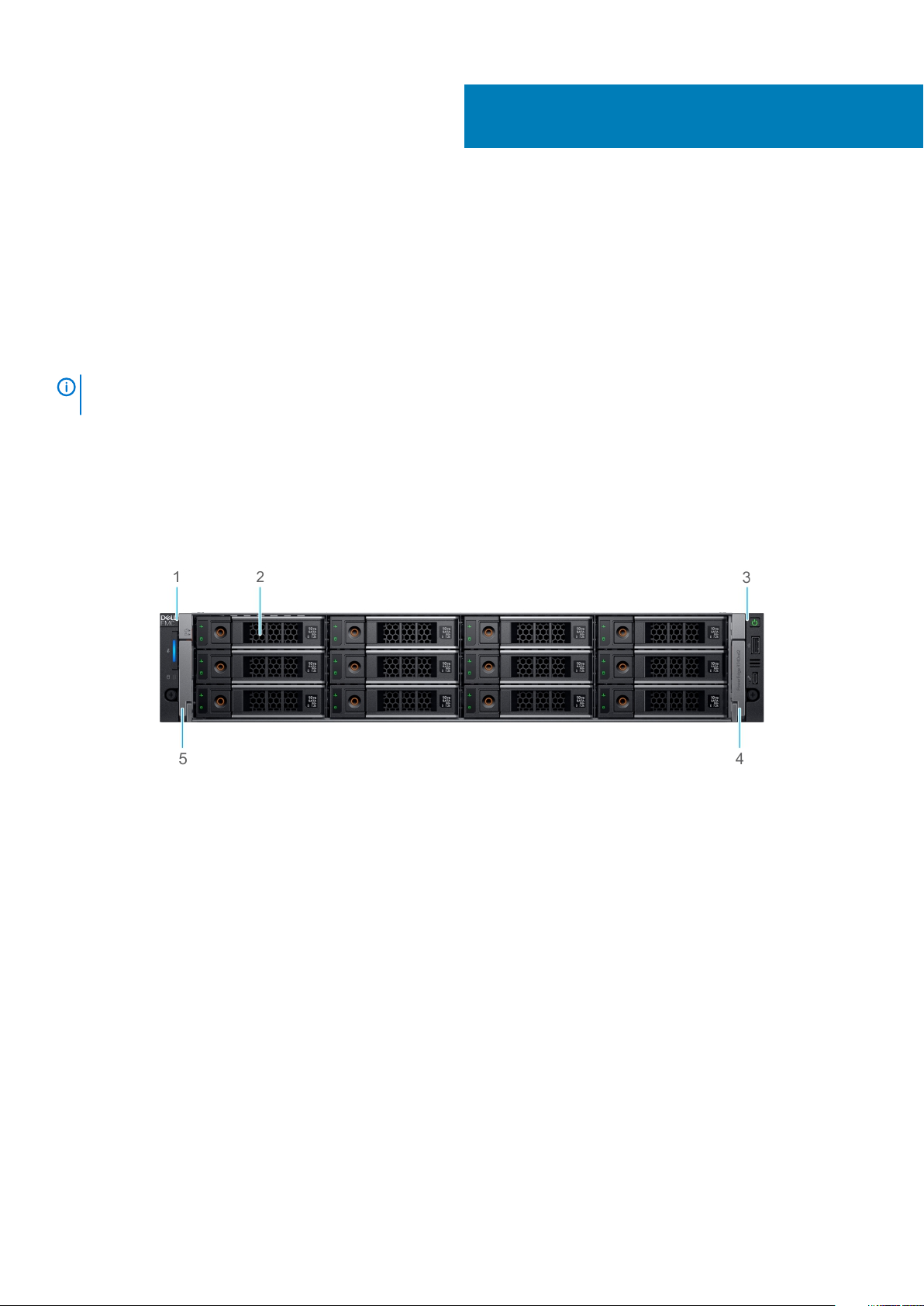
Front view of the system
2
Figure 1. Front view of 24 x 3.5-inch drive system
Left control panel 2. Drives (12)
1.
3. Right control panel 4. Right release latch
5. Left release latch
Dell EMC XC740xd2 system overview 7
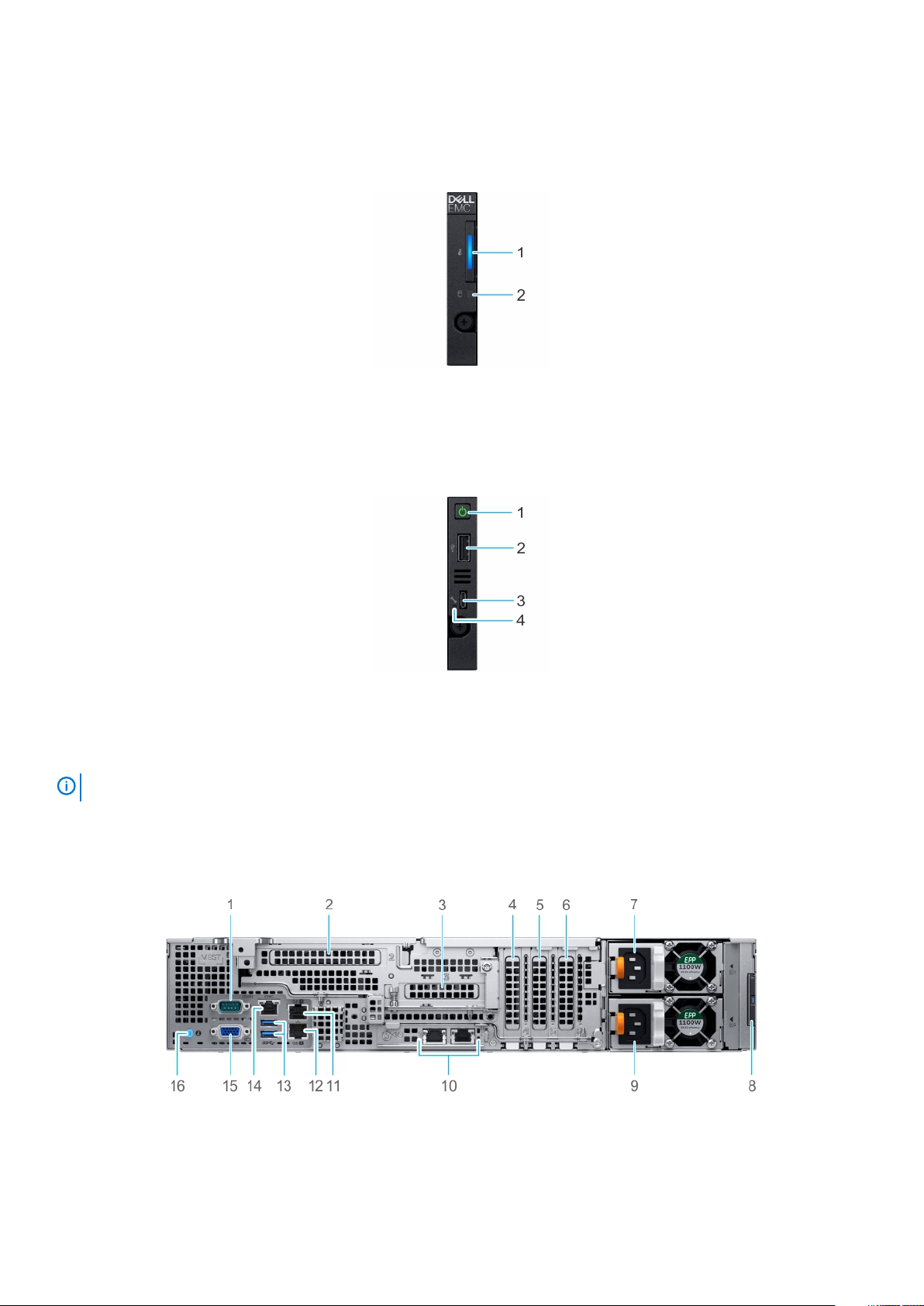
Control panels
Left control panel
Figure 2. Left control panel view
1. System health and system ID indicator
2. Drive indicator
Right control panel
Figure 3. Right control panel view
Power button 2. USB 2.0-compliant port
1.
3. Micro USB 2.0-compliant port for iDRAC Direct 4. iDRAC LED indicator
NOTE: For more information on the ports, see the ports and connectors specifications section.
Rear view of the system
Figure 4. Back panel features of system with butterfly riser
1.
Serial port 2. Butterfly riser full-height (slot 2)
8 Dell EMC XC740xd2 system overview
3. Butterfly riser low-profile (slot 3) 4. Low-profile PCIe expansion card (slot 4)
5. Low-profile PCIe expansion card (slot 5) 6. Low-profile PCIe expansion card (slot 6)
7. Power supply unit (PSU 1) 8. Information tag
9. Power supply unit (PSU 2) 10. LOM ethernet port (2)
11. Ethernet port (Gb1) 12. Ethernet port (Gb2)
13. USB 3.0 port (2) 14. iDRAC9 dedicated network port
15. VGA port 16. System identification button
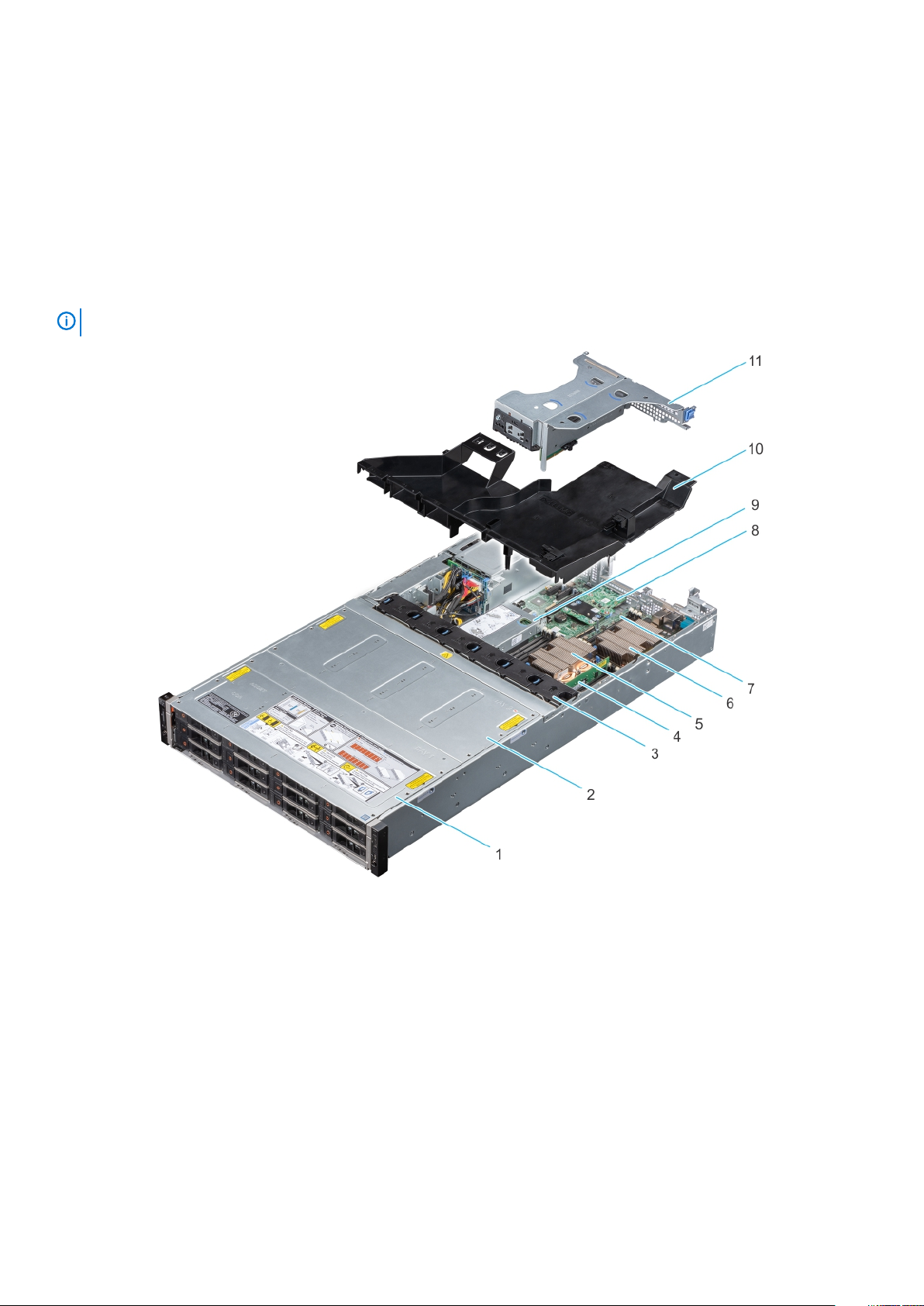
Inside the system
NOTE: Components that are hot swappable are marked orange and touch points on the components are marked blue.
Figure 5. Inside the system with butterfly riser
1.
Drive bay 1 2. Drive bay 2
3. Fans (6) 4. Memory module
5. Processor and heatsink module 1 6. Processor and heatsink module 2
7. System board 8. LOM riser card
9. Internal PERC riser 10. Air shroud
11. Butterfly riser
Locating the information tag of your system
Your system is identified by a unique Express Service Code and Service Tag number. You can view the Express Service Code and Service
Tag by pulling out the information tag located on the rear of the system. Alternatively, the information may be on a sticker on the chassis
of the system. Alternatively, the information may be on the Mini Enterprise Service Tag (MEST) label on the chassis, on the rear of the
system. This information is used by Dell to route support calls to the appropriate personnel.
Dell EMC XC740xd2 system overview
9

Figure 6. Locating the information tag of your system
1. Information tag (Top view)
2. iDRAC MAC address and iDRAC secure password label
3. Express Service Tag
4. QRL label
5. Information tag (back view)
10 Dell EMC XC740xd2 system overview
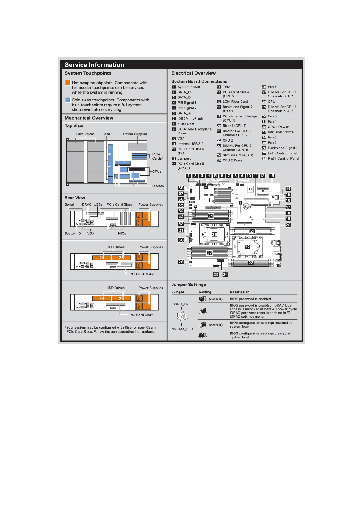
System Information Label
Figure 7. XC740xd2 – Service information
Dell EMC XC740xd2 system overview
11
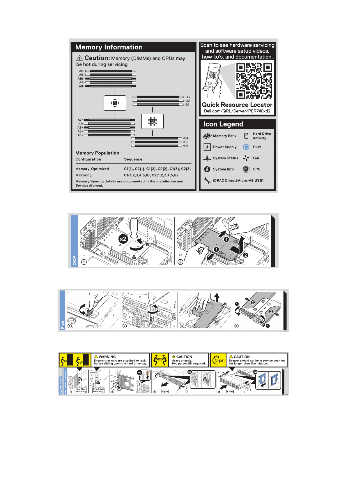
Figure 8. Memory information
Figure 9. OCP installation
Figure 10. Riser installation
Figure 11. Drive Bays Operation
12
Dell EMC XC740xd2 system overview
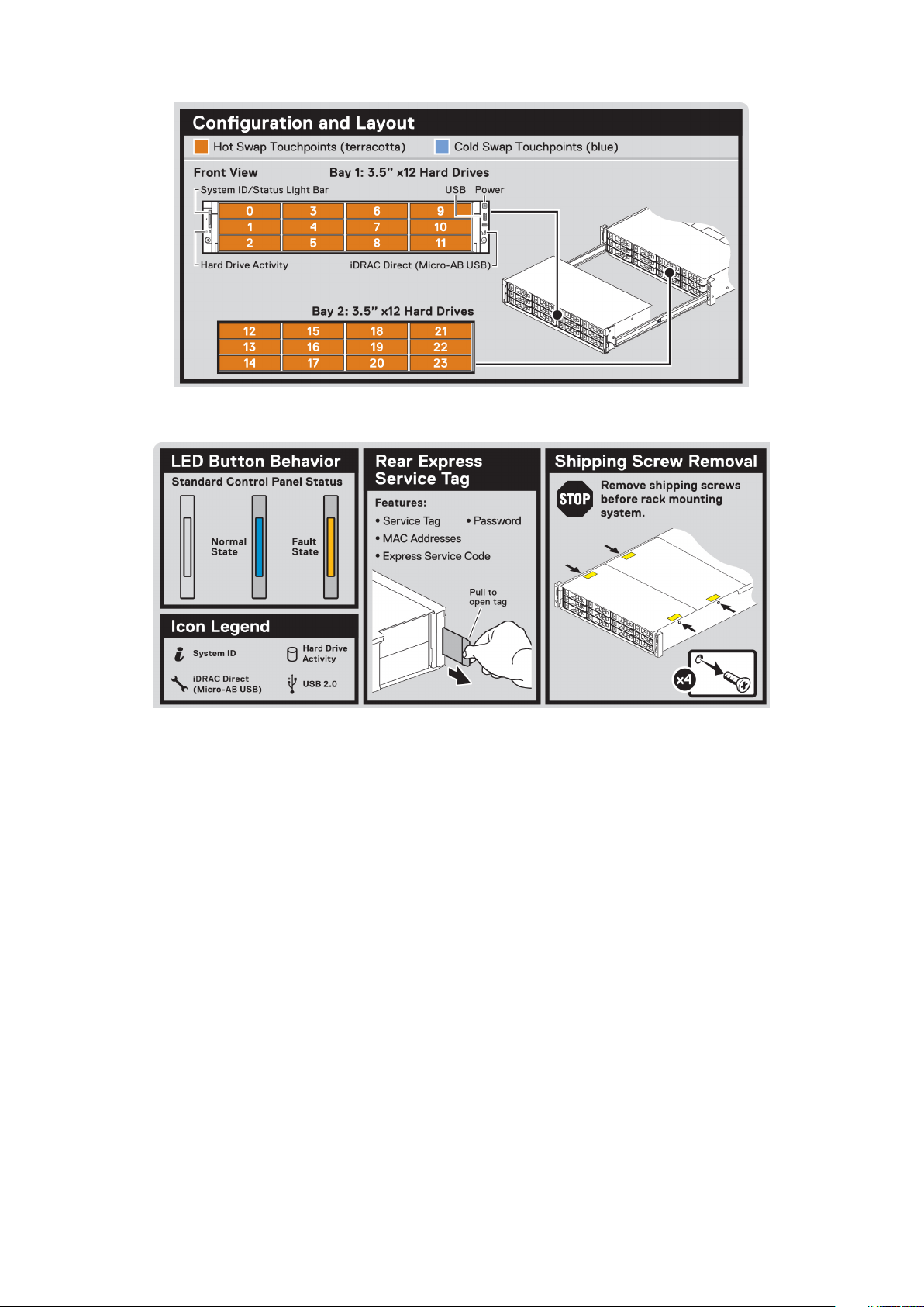
Figure 12. Drive configuration and layout
Figure 13. System LED indicator and Express Service Tag
Dell EMC XC740xd2 system overview
13

Initial system setup and configuration
Setting up your system
Perform the following steps to set up your system:
Steps
1. Unpack the system.
2. Remove the shipping screws from the sides of the system, before installing it in the rack.
CAUTION: Do not attempt to lift the system by yourself to avoid potential injury. Do not apply uneven force to either
end of the system to prevent the chassis from distorting or bending. Keep the system parallel to the ground when
lifting and moving it.
3. Install the system into the rack. For more information about installing the system into the rack, see the Rail Installation Guide at
www.dell.com/xcseriesmanuals.
4. Connect the peripherals to the system.
5. Connect the system to its electrical outlet.
6. Power on the system by pressing the power button or by using iDRAC.
7. Power on the attached peripherals.
For more information about setting up your system, see the Getting Started Guide that shipped with your system.
3
iDRAC configuration
The Integrated Dell Remote Access Controller (iDRAC) is designed to make system administrators more productive and improve the
overall availability of Dell systems. iDRAC alerts administrators about system issues and enables them to perform remote system
management. This reduces the need for physical access to the system.
Options to set up iDRAC IP address
To enable communication between your system and iDRAC, you must first configure the network settings based on your network
infrastructure.
NOTE:
This option is set to DHCP by Default. You can set up the IP address by using one of the following interfaces:
Interfaces
iDRAC Settings
utility
Dell Deployment
Toolkit
Dell Lifecycle
Controller
iDRAC Direct and
Quick Sync 2
(optional)
For static IP configuration, you must request for it at the time of purchase.
Document/Section
Dell Integrated Dell Remote Access Controller User's Guide at www.dell.com/xcseriesmanuals
Dell Deployment Toolkit User’s Guide at www.dell.com/openmanagemanuals > OpenManage Deployment Toolkit
Dell Lifecycle Controller User’s Guide at www.dell.com/xcseriesmanuals
See Dell Integrated Dell Remote Access Controller User's Guide at www.dell.com/xcseriesmanuals
NOTE: To access iDRAC, ensure that you connect the ethernet cable to the iDRAC9 dedicated network port. You can
also access iDRAC through the shared LOM mode, if you have opted for a system that has the shared LOM mode
enabled.
14 Initial system setup and configuration

Log in to iDRAC
You can log in to iDRAC as:
• iDRAC user
• Microsoft Active Directory user
• Lightweight Directory Access Protocol (LDAP) user
If you have opted for secure default access to iDRAC, you must use the iDRAC secure default password available on the system
Information tag. If you have not opted for secure default access to iDRAC, then use the default user name and password –
calvin. You can also log in by using your Single Sign-On or Smart Card.
NOTE: You must have the iDRAC credentials to log in to iDRAC.
NOTE: Ensure that you change the default user name and password after setting up the iDRAC IP address.
NOTE: The Intel Quick Assist Technology (QAT) on the Dell EMC XC740xd2 is supported with chipset integration and is
enabled through an optional license. The license files are enabled on the sleds through iDRAC.
For more information about drivers, documentation, and white papers on the Intel QAT, see https://01.org/intel-quickassist-technology.
For more information about logging in to the iDRAC and iDRAC licenses, see the latest Integrated Dell Remote Access Controller User's
Guide at www.dell.com/xcseriesmanuals.
You can also access iDRAC by using RACADM. For more information, see the RACADM Command Line Interface Reference Guide at
www.dell.com/xcseriesmanuals.
root and
Options to install the operating system
If the system is shipped without an operating system, install a supported operating system by using one of the following resources:
Table 1. Resources to install the operating system
Resources Location
iDRAC www.dell.com/idracmanuals
Lifecycle Controller www.dell.com/idracmanuals > Lifecycle Controller
OpenManage Deployment Toolkit www.dell.com/openmanagemanuals > OpenManage Deployment
Toolkit
Dell certified VMware ESXi www.dell.com/virtualizationsolutions
Methods to download firmware and drivers
You can download the firmware and drivers by using any of the following methods:
Table 2. Firmware and drivers
Methods Location
From the Dell EMC support site www.dell.com/support/home
Using Dell Remote Access Controller Lifecycle Controller (iDRAC
with LC)
Using iDRAC virtual media www.dell.com/idracmanuals
www.dell.com/idracmanuals
Downloading drivers and firmware
Dell EMC recommends that you download and install the latest BIOS, drivers, and systems management firmware on your system.
Prerequisites
Ensure that you clear the web browser cache before downloading the drivers and firmware.
Initial system setup and configuration
15

Steps
1. Go to www.dell.com/support/home.
2. In the Drivers & Downloads section, type the Service Tag of your system in the Enter a Service Tag or product ID box, and then
click
Submit.
NOTE: If you do not have the Service Tag, select Detect Product to allow the system to automatically detect the
Service Tag, or click View products, and navigate to your product.
Click Drivers & Downloads.
3.
The drivers that are applicable to your system are displayed.
4. Download the drivers to a USB drive, CD, or DVD.
16 Initial system setup and configuration

Pre-operating system management
applications
You can manage basic settings and features of a system without booting to the operating system by using the system firmware.
Topics:
• Options to manage the pre-operating system applications
• System Setup
• Dell Lifecycle Controller
• Boot Manager
• PXE boot
Options to manage the pre-operating system applications
Your system has the following options to manage the pre-operating system applications:
• System Setup
• Dell Lifecycle Controller
• Boot Manager
• Preboot Execution Environment (PXE)
4
System Setup
By using the System Setup screen, you can configure the BIOS settings, iDRAC settings, and device settings of your system.
NOTE:
browser, press F1.
You can access system setup by one of the following:
• Standard graphical browser—The browser is enabled by default.
• Text browser—The browser is enabled by using Console Redirection.
Viewing System Setup
To view the System Setup screen, perform the following steps:
Steps
1. Power on or restart your system.
2. Press F2 immediately after you see the following message:
Help text for the selected field is displayed in the graphical browser by default. To view the help text in the text
F2 = System Setup
NOTE:
restart your system and try again.
If your operating system begins to load before you press F2, wait for the system to finish booting, and then
System Setup details
The System Setup Main Menu screen details are explained as follows:
Pre-operating system management applications 17

Option Description
System BIOS Enables you to configure BIOS settings.
iDRAC Settings Enables you to configure the iDRAC settings.
The iDRAC settings utility is an interface to set up and configure the iDRAC parameters by using UEFI (Unified
Extensible Firmware Interface). You can enable or disable various iDRAC parameters by using the iDRAC settings
utility. For more information about this utility, see
www.dell.com/xcseriesmanuals.
Device Settings Enables you to configure device settings.
Integrated Dell Remote Access Controller User’s Guide at
System BIOS
You can use the System BIOS screen to edit specific functions such as boot order, system password, and setup password, set the SATA
and PCIe NVMe RAID mode, and enable or disable USB ports.
Viewing System BIOS
To view the System BIOS screen, perform the following steps:
Steps
1. Power on or restart your system.
2. Press F2 immediately after you see the following message:
F2 = System Setup
NOTE:
restart the system and try again.
3. On the System Setup Main Menu screen, click System BIOS.
If the operating system begins to load before you press F2, wait for the system to finish booting, and then
System BIOS Settings details
About this task
The System BIOS Settings screen details are explained as follows:
Option
System
Information
Memory Settings Provides information and options related to the installed memory.
Processor
Settings
SATA Settings Provides options to enable or disable the integrated SATA controller and ports.
Boot Settings Provides options to specify the Boot mode (BIOS or UEFI). Enables you to modify UEFI and BIOS boot settings.
Network Settings Provides options to manage the UEFI network settings and boot protocols.
Description
Provides information about the system such as the system model name, BIOS version, and Service Tag.
Provides information and options related to the processor such as speed and cache size.
Legacy network settings are managed from the Device Settings menu.
Integrated Devices Provides options to manage integrated device controllers and ports, specifies related features and options.
Serial
Communication
System Profile
Settings
System Security Provides options to configure the system security settings, such as system password, setup password, Trusted
18 Pre-operating system management applications
Provides options to manage the serial ports, their related features and options.
Provides options to change the processor power management settings, and memory frequency.
Platform Module (TPM) security, and UEFI secure boot. It also manages the power button on the system.

Option Description
Redundant OS
Control
Miscellaneous
Settings
Sets the redundant OS information for redundant OS control.
Provides options to change the system date and time.
System Information
You can use the System Information screen to view system properties such as Service Tag, system model name, and BIOS version.
Viewing System Information
To view the System Information screen, perform the following steps:
Steps
1. Power on or restart your system.
2. Press F2 immediately after you see the following message:
F2 = System Setup
NOTE: If your operating system begins to load before you press F2, wait for the system to finish booting, and then
restart your system and try again.
3. On the System Setup Main Menu screen, click System BIOS.
4. On the System BIOS screen, click System Information.
System Information details
About this task
The System Information screen details are explained as follows:
Option
System Model
Name
System BIOS
Version
System
Management
Engine Version
System Service
Tag
System
Manufacturer
System
Manufacturer
Contact
Information
System CPLD
Version
Secondary System
CPLD Version
UEFI Compliance
Version
Description
Specifies the system model name.
Specifies the BIOS version installed on the system.
Specifies the current version of the Management Engine firmware.
Specifies the system Service Tag.
Specifies the name of the system manufacturer.
Specifies the contact information of the system manufacturer.
Specifies the current version of the system complex programmable logic device (CPLD) firmware.
Specifies the current version of the system complex programmable logic device (CPLD) firmware.
Specifies the UEFI compliance level of the system firmware.
Pre-operating system management applications 19

Memory Settings
You can use the Memory Settings screen to view all the memory settings and enable or disable specific memory functions, such as
system memory testing and node interleaving.
Viewing Memory Settings
To view the Memory Settings screen, perform the following steps:
Steps
1. Power on or restart your system.
2. Press F2 immediately after you see the following message:
F2 = System Setup
NOTE: If the operating system begins to load before you press F2, wait for the system to finish booting, and then
restart the system and try again.
3. On the System Setup Main Menu screen, click System BIOS.
4. On the System BIOS screen, click Memory Settings.
Memory Settings details
About this task
The Memory Settings screen details are explained as follows:
Option
System Memory
Size
System Memory
Type
System Memory
Speed
System Memory
Voltage
Video Memory Specifies the amount of video memory.
System Memory
Testing
Current State of
Memory Operating
Mode
Node Interleaving Specifies if Non-Uniform Memory Architecture (NUMA) is supported. If this field is set to Enabled, memory
ADDDC Setting Enables or disables ADDDC Setting feature. When Adaptive Double DRAM Device Correction (ADDDC) is
Opportunistic
Self-Refresh
Description
Specifies the memory size in the system.
Specifies the type of memory installed in the system.
Specifies the system memory speed.
Specifies the system memory voltage.
Specifies whether the system memory tests are run during system boot. Options are Enabled and Disabled. This
option is set to Disabled by default.
Specifies the current state of the memory operating mode.
interleaving is supported if a symmetric memory configuration is installed. If this field is set to Disabled, the
system supports NUMA (asymmetric) memory configurations. This option is set to Disabled by default.
enabled, failing DRAM's are dynamically mapped out. When set to Enabled it can have some impact to system
performance under certain workloads. This feature is applicable for x4 DIMMs only. This option is set to Enabled
by default.
Enables or disables opportunistic self-refresh feature. This option is set to Disabled by default.
20 Pre-operating system management applications

Processor Settings
You can use the Processor Settings screen to view the processor settings and perform specific functions such as enabling virtualization
technology, hardware prefetcher, logical processor idling.
Viewing Processor Settings
To view the Processor Settings screen, perform the following steps:
Steps
1. Power on or restart your system.
2. Press F2 immediately after you see the following message:
F2 = System Setup
NOTE: If your operating system begins to load before you press F2, wait for the system to finish booting, and then
restart your system and try again.
3. On the System Setup Main Menu screen, click System BIOS.
4. On the System BIOS screen, click Processor Settings.
Processor Settings details
About this task
The Processor Settings screen details are explained as follows:
Option
Logical Processor
Virtualization
Technology
Adjacent Cache
Line Prefetch
Hardware
Prefetcher
Software
Prefetcher
DCU Streamer
Prefetcher
DCU IP Prefetcher Enables or disables the Data Cache Unit (DCU) IP prefetcher. This option is set to Enabled by default.
Sub NUMA Cluster Enables or disables the Sub NUMA Cluster. This option is set to Disabled by default.
UPI Prefetch Enables you to get the memory read started early on DDR bus. The Ultra Path Interconnect (UPI) Rx path will
Logical Processor
Idling
Configurable TDP Enables you to configure the TDP level. The available options are Nominal, Level 1, and Level 2. This option is set
Description
Enables or disables the logical processors and displays the number of logical processors. If this option is set to
Enabled, the BIOS displays all the logical processors. If this option is set to Disabled, the BIOS displays only one
logical processor per core. This option is set to Enabled by default.
Enables or disables the virtualization technology for the processor. This option is set to Enabled by default.
Optimizes the system for applications that need high utilization of sequential memory access. This option is set to
Enabled by default. You can disable this option for applications that need high utilization of random memory
access.
Enables or disables the hardware prefetcher. This option is set to Enabled by default.
Enables or disables the software prefetcher. This option is set to Enabled by default.
Enables or disables the Data Cache Unit (DCU) streamer prefetcher. This option is set to Enabled by default.
spawn the speculative memory read to Integrated Memory Controller (iMC) directly. This option is set to Enabled
by default.
Enables you to improve the energy efficiency of a system. It uses the operating system core parking algorithm and
parks some of the logical processors in the system which in turn allows the corresponding processor cores to
transition into a lower power idle state. This option can only be enabled if the operating system supports it. It is set
to Disabled by default.
to Nominal by default.
NOTE: This option is only available on certain stock keeping units (SKUs) of the processors.
Pre-operating system management applications 21

Option Description
SST-Performance
Profile
x2APIC Mode Enables or disables the x2APIC mode. This option is set to Disabled by default.
Number of Cores
per Processor
Processor Core
Speed
Processor n
Enables you to reconfigure the processor using Speed Select Technology.
Controls the number of enabled cores in each processor. This option is set to All by default.
Specifies the maximum core frequency of the processor.
NOTE: Depending on the number of processors, there might be up to n processors listed.
The following settings are displayed for each processor installed in the system:
Option Description
Family-ModelStepping
Brand Specifies the brand name.
Level 2 Cache Specifies the total L2 cache.
Level 3 Cache Specifies the total L3 cache.
Number of Cores Specifies the number of cores per processor.
Maximum Memory
Capacity
Microcode Specifies the microcode.
Specifies the family, model, and stepping of the processor as defined by Intel.
Specifies the maximum memory capacity per processor.
SATA Settings
NOTE:
You can use the SATA Settings screen to view the settings of SATA devices and enable SATA and PCIe NVMe RAID mode on your
system.
XC series does not support SATA settings.
Viewing SATA Settings
To view the SATA Settings screen, perform the following steps:
Steps
1. Power on or restart your system.
2. Press F2 immediately after you see the following message:
F2 = System Setup
NOTE:
restart your system and try again.
3. On the System Setup Main Menu screen, click System BIOS.
4. On the System BIOS screen, click SATA Settings.
If your operating system begins to load before you press F2, wait for the system to finish booting, and then
SATA Settings details
About this task
The SATA Settings screen details are explained as follows:
22
Pre-operating system management applications

Option Description
Embedded SATA Enables the embedded SATA option to be set to AHCI Mode, or RAID Mode. This option is set to AHCI Mode
by default.
Security Freeze
Lock
Write Cache Enables or disables the command for the embedded SATA drives during POST. This option is set to Disabled by
Port n Enables you to set the drive type of the selected device.
Enables you to send Security Freeze Lock command to the embedded SATA drives during POST. This option is
applicable only for AHCI mode. This option is set to Enabled by default.
default.
For AHCI Mode or RAID Mode, BIOS support is always enabled.
Option Description
Model Specifies the drive model of the selected device.
Drive Type Specifies the type of drive attached to the SATA port.
Capacity Specifies the total capacity of the drive. This field is undefined for removable media
devices such as optical drives.
Boot Settings
You can use the Boot Settings screen to set the boot mode to either BIOS or UEFI. It also enables you to specify the boot order.
• UEFI: The Unified Extensible Firmware Interface (UEFI) is a new interface between operating systems and platform firmware. The
interface consists of data tables with platform related information, boot and runtime service calls that are available to the operating
system and its loader. The following benefits are available when the Boot Mode is set to UEFI:
• Support for drive partitions larger than 2 TB.
• Enhanced security (e.g., UEFI Secure Boot).
• Faster boot time.
• BIOS: The BIOS Boot Mode is the legacy boot mode. It is maintained for backward compatibility.
Viewing Boot Settings
To view the Boot Settings screen, perform the following steps:
Steps
1. Power on or restart your system.
2. Press F2 immediately after you see the following message:
F2 = System Setup
NOTE:
restart your system and try again.
3. On the System Setup Main Menu screen, click System BIOS.
4. On the System BIOS screen, click Boot Settings.
If your operating system begins to load before you press F2, wait for the system to finish booting, and then
Boot Settings details
About this task
The Boot Settings screen details are explained as follows:
Option
Boot Mode Enables you to set the boot mode of the system.
Description
CAUTION: Switching the boot mode may prevent the system from booting if the operating system
is not installed in the same boot mode.
Pre-operating system management applications 23

Option Description
If the operating system supports UEFI, you can set this option to UEFI. Setting this field to BIOS enables
compatibility with non-UEFI operating systems. This option is set to UEFI by default.
NOTE: Setting this field to UEFI disables the BIOS Boot Settings menu.
Boot Sequence
Retry
Hard-Disk Failover Specifies the drive that is booted in the event of a drive failure. The devices are selected in the Hard-Disk Drive
Generic USB Boot Enables or disables the USB boot option. This option is set to Disabled by default.
Hard-disk Drive
Placeholder
BIOS Boot
Settings
UEFI Boot
Settings
UEFI Boot
Sequence
Boot Options
Enable/Disable
Enables or disables the Boot Sequence Retry feature. If this option is set to Enabled and the system fails to
boot, the system re-attempts the boot sequence after 30 seconds. This option is set to Enabled by default.
Sequence on the Boot Option Setting menu. When this option is set to Disabled, only the first drive in the list
is attempted to boot. When this option is set to Enabled, all drives are attempted to boot in the order selected in
the Hard-Disk Drive Sequence. This option is not enabled for UEFI Boot Mode. This option is set to Disabled
by default.
Enables or disables the Hard-disk drive placeholder option. This option is set to Disabled by default.
Enables or disables BIOS boot options.
NOTE: This option is enabled only if the boot mode is BIOS.
Enables or disables UEFI Boot options.
The Boot options include IPv4 PXE and IPv6 PXE. This option is set to IPv4 by default.
NOTE: This option is enabled only if the boot mode is UEFI.
Enables you to change the boot device order.
Enables you to select the enabled or disabled boot devices.
Choosing system boot mode
System Setup enables you to specify one of the following boot modes for installing your operating system:
• BIOS boot mode (the default) is the standard BIOS-level boot interface.
• UEFI boot mode (the default), is an enhanced 64-bit boot interface.
If you have configured your system to boot to UEFI mode, it replaces the system BIOS.
1. From the System Setup Main Menu, click Boot Settings, and select Boot Mode.
2. Select the UEFI boot mode you want the system to boot into.
CAUTION:
the same boot mode.
3. After the system boots in the specified boot mode, proceed to install your operating system from that mode.
NOTE:
systems do not support UEFI and can only be installed from the BIOS boot mode.
NOTE: For the latest information about supported operating systems, go to www.dell.com/ossupport.
Switching the boot mode may prevent the system from booting if the operating system is not installed in
Operating systems must be UEFI-compatible to be installed from the UEFI boot mode. DOS and 32-bit operating
Changing boot order
About this task
You may have to change the boot order if you want to boot from a USB key or an optical drive. The following instructions may vary if you
have selected BIOS for Boot Mode.
NOTE:
Ensure that you do not alter the boot order.
24 Pre-operating system management applications

Steps
1. On the System Setup Main Menu screen, click System BIOS > Boot Settings > UEFI/BIOS Boot Settings > UEFI/BIOS Boot
Sequence.
2. Click Exit, and then click Yes to save the settings on exit.
Network Settings
You can use the Network Settings screen to modify UEFI PXE, iSCSI, and HTTP boot settings. The network settings option is available
only in the UEFI mode.
NOTE: BIOS does not control network settings in the BIOS mode. For the BIOS boot mode, the optional Boot ROM of
the network controllers handles the network settings.
Viewing Network Settings
To view the Network Settings screen, perform the following steps:
Steps
1. Power on or restart your system.
2. Press F2 immediately after you see the following message:
F2 = System Setup
NOTE: If your operating system begins to load before you press F2, wait for the system to finish booting, and then
restart your system and try again.
3. On the System Setup Main Menu screen, click System BIOS.
4. On the System BIOS screen, click Network Settings.
Network Settings screen details
The Network Settings screen details are explained as follows:
About this task
Option
UEFI PXE Settings
PXE Device n
Settings (n = 1 to
4)
UEFI HTTP
Settings
HTTP Device n
Settings (n = 1 to
4)
Description
Options Description
PXE Device n (n =
1 to 4)
Enables you to control the configuration of the PXE device.
Enables or disables the device. When enabled, a UEFI PXE boot option is created for the
device.
Options Description
HTTP Device (n =
1 to 4)
Enables you to control the configuration of the HTTP device.
Enables or disables the device. When enabled, a UEFI HTTP boot option is created for the
device.
Pre-operating system management applications 25

Integrated Devices
You can use the Integrated Devices screen to view and configure the settings of all integrated devices including the video controller,
integrated RAID controller, and the USB ports.
Viewing Integrated Devices
To view the Integrated Devices screen, perform the following steps:
Steps
1. Power on or restart your system.
2. Press F2 immediately after you see the following message:
F2 = System Setup
NOTE: If your operating system begins to load before you press F2, wait for the system to finish booting, and then
restart your system and try again.
3. On the System Setup Main Menu screen, click System BIOS.
4. On the System BIOS screen, click Integrated Devices.
Integrated Devices details
About this task
The Integrated Devices screen details are explained as follows:
Option
iDRAC Direct USB
Port
I/OAT DMA
Engine
Embedded Video
Controller
Current State of
Embedded Video
Controller
SR-IOV Global
Enable
OS Watchdog
Timer
Empty Slot Unhide Enables or disables the root ports of all the empty slots that are accessible to the BIOS and OS. This option is set
Memory Mapped
I/O above 4 GB
Description
The iDRAC Direct USB port is managed by iDRAC exclusively with no host visibility. This option is set to ON or
OFF. When set to OFF, iDRAC does not detect any USB devices installed in this managed port. This option is set
to On by default.
Enables or disables the I/O Acceleration Technology (I/OAT) option. I/OAT is a set of DMA features designed to
accelerate network traffic and lower CPU utilization. Enable only if the hardware and software support the
feature.This option is set to Disabled by default.
Enables or disables the use of Embedded Video Controller as the primary display. When set to Enabled, the
Embedded Video Controller is used as the primary display even if add-in graphic cards are installed. When set to
Disabled, an add-in graphics card is used as the primary display. BIOS will output displays to both the primary
add-in video and the embedded video during POST and pre-boot environment. The embedded video is disabled
before the operating system boots. This option is set to
NOTE: When there are multiple add-in graphic cards installed in the system, the first card
discovered during PCI enumeration is selected as the primary video. You might have to re-arrange
the cards in the slots in order to control which card is the primary video.
Displays the current state of the embedded video controller. The Current State of Embedded Video
Controller option is a read-only field. If the Embedded Video Controller is the only display capability in the system
(that is, no add-in graphics card is installed), then the Embedded Video Controller is automatically used as the
primary display even if the Embedded Video Controller setting is set to Disabled.
Enables or disables the BIOS configuration of Single Root I/O Virtualization (SR-IOV) devices. This option is set to
Disabled by default.
If your system stops responding, this watchdog timer aids in the recovery of your operating system. When this
option is set to Enabled, the operating system initializes the timer. When this option is set to Disabled (the
default), the timer does not have any effect on the system.
to Enabled by default.
Enables or disables the support for the PCIe devices that need large amounts of memory. Enable this option only
for 64-bit operating systems. This option is set to Enabled by default.
Enabled by default.
26 Pre-operating system management applications

Serial Communication
You can use the Serial Communication screen to view the properties of the serial communication port.
Viewing Serial Communication
To view the Serial Communication screen, perform the following steps:
Steps
1. Power on or restart your system.
2. Press F2 immediately after you see the following message:
F2 = System Setup
NOTE: If your operating system begins to load before you press F2, wait for the system to finish booting, and then
restart your system and try again.
3. On the System Setup Main Menu screen, click System BIOS.
4. On the System BIOS screen, click Serial Communication.
Serial Communication details
About this task
The Serial Communication screen details are explained as follows:
Option
Serial Port
Address
Failsafe Baud Rate Specifies the failsafe baud rate for console redirection. The BIOS attempts to determine the baud rate
Remote Terminal
Type
Redirection After
Boot
Description
Enables you to set the port address for serial device. This field sets the serial port address to either COM1 or
COM2 (COM1=0x3F8, COM2=0x2F8).
NOTE: You can use only Serial Device 2 for the Serial Over LAN (SOL) feature. To use console
redirection by SOL, configure the same port address for console redirection and the serial device.
NOTE: Every time the system boots, the BIOS syncs the serial MUX setting saved in iDRAC. The
serial MUX setting can independently be changed in iDRAC. Loading the BIOS default settings
from within the BIOS setup utility may not always revert the serial MUX setting to the default
setting of Serial Device 1.
automatically. This failsafe baud rate is used only if the attempt fails, and the value must not be changed. This
option is set to 115200 by default.
Enables you to set the remote console terminal type. This option is set to VT100/VT220 by default.
Enables or disables the BIOS console redirection when the operating system is loaded. This option is set to
Enabled by default.
System Profile Settings
You can use the System Profile Settings screen to enable specific system performance settings such as power management.
Viewing System Profile Settings
To view the System Profile Settings screen, perform the following steps:
Steps
1. Power on or restart your system.
2. Press F2 immediately after you see the following message:
F2 = System Setup
Pre-operating system management applications
27

NOTE: If your operating system begins to load before you press F2, wait for the system to finish booting, and then
restart your system and try again.
3. On the System Setup Main Menu screen, click System BIOS.
4. On the System BIOS screen, click System Profile Settings.
System Profile Settings details
About this task
The System Profile Settings screen details are explained as follows:
Option Description
System Profile Sets the system profile. If you set the System Profile option to a mode other than Custom, the BIOS
automatically sets the rest of the options. You can only change the rest of the options if the mode is set to
Custom.This option is set to Performance Per Watt Optimized (DAPC) by default. DAPC is Dell Active
Power Controller.
NOTE: All the parameters on the system profile setting screen are available only when the System
Profile option is set to Custom.
CPU Power
Management
Memory
Frequency
Turbo Boost Enables or disables the processor to operate in the turbo boost mode. This option is set to Enabled by default.
C1E Enables or disables the processor to switch to a minimum performance state when it is idle. This option is set to
Write Data CRC Enables or disables the Write Data CRC. This option is set to Disabled by default.
Memory Patrol
Scrub
Memory Refresh
Rate
Uncore Frequency Enables you to select the Processor Uncore Frequency option.Dynamic mode enables the processor to
Energy Efficient
Policy
Number of Turbo
Boost Enabled
Cores for
Processor 1
Monitor/Mwait Enables the Monitor/Mwait instructions in the processor. This option is set to Enabled for all system profiles,
Sets the CPU power management. This option is set to System DBPM (DAPC) by default. DBPM is DemandBased Power Management.
Sets the speed of the system memory. You can select Maximum Performance, Maximum Reliability, or a
specific speed. This option is set to Maximum Performance by default.
Enabled by default.
Sets the memory patrol scrub frequency. This option is set to Standard by default.
Sets the memory refresh rate to either 1x or 2x. This option is set to 1x by default.
optimize power resources across cores and uncores during runtime. The optimization of the uncore frequency to
either save power or optimize performance is influenced by the setting of the Energy Efficiency Policy option.
Enables you to select the Energy Efficient Policy option.
The CPU uses the setting to manipulate the internal behavior of the processor and determines whether to target
higher performance or better power savings. This option is set to Balanced Performance by default.
NOTE: If there are two processors installed in the system, you will see an entry for Number of
Turbo Boost Enabled Cores for Processor 2.
Controls the number of turbo boost enabled cores for Processor 1. The maximum number of cores is enabled by
default.
except Custom by default.
NOTE: This option can be disabled only if the C States option in the Custom mode is set to
disabled.
NOTE: When C States is set to Enabled in the Custom mode, changing the Monitor/Mwait setting
does not impact the system power or performance.
CPU Interconnect
Bus Link Power
Management
28 Pre-operating system management applications
Enables or disables the CPU Interconnect Bus Link Power Management. This option is set to Enabled by default.

Option Description
PCI ASPM L1 Link
Power
Management
Enables or disables the PCI ASPM L1 Link Power Management. This option is set to Enabled by default.
System Security
You can use the System Security screen to perform specific functions such as setting the system password, setup password and
disabling the power button.
Viewing System Security
To view the System Security screen, perform the following steps:
Steps
1. Power on or restart your system.
2. Press F2 immediately after you see the following message:
F2 = System Setup
NOTE: If your operating system begins to load before you press F2, wait for the system to finish booting, and then
restart your system and try again.
3. On the System Setup Main Menu screen, click System BIOS.
4. On the System BIOS screen, click System Security.
System Security Settings details
About this task
The System Security Settings screen details are explained as follows:
Option
CPU AES-NI Improves the speed of applications by performing encryption and decryption by using the Advanced Encryption
Setup Password Enables you to set the system setup password. This option is read-only if the password jumper is not installed in
Password Status Enables you to lock the system password. This option is set to Unlocked by default.
TPM Security
Intel(R) TXT Enables you to set the Intel Trusted Execution Technology (TXT) option. To enable the Intel TXT option,
Power Button Enables you to set the power button on the front of the system. This option is set to Enabled by default.
AC Power
Recovery
UEFI Variable
Access
Secure Boot Enables Secure Boot, where the BIOS authenticates each pre-boot image by using the certificates in the Secure
Description
Standard Instruction Set (AES-NI). This option is set to Enabled by default.
the system.
NOTE: The TPM menu is available only when the TPM module is installed.
Enables you to control the reporting mode of the TPM. The TPM Security option is set to Off by default. You
can only modify the TPM Status, TPM Activation, and the Intel TXT fields if the TPM Status field is set to either
On with Pre-boot Measurements or On without Pre-boot Measurements.
virtualization technology and TPM Security must be enabled with Pre-boot measurements. This option is set to
Off by default.
Sets how the system behaves after AC power is restored to the system. This option is set to Last by default.
Provides varying degrees of securing UEFI variables. When set to Standard (the default), UEFI variables are
accessible in the operating system per the UEFI specification. When set to Controlled, selected UEFI variables
are protected in the environment, and new UEFI boot entries are forced to be at the end of the current boot
order.
Boot Policy. Secure Boot is set to Disabled by default.
Pre-operating system management applications 29

Option Description
Secure Boot
Policy
Secure Boot Mode Enables you to configure how the BIOS uses the Secure Boot Policy Objects (PK, KEK, db, dbx).
When Secure Boot policy is set to Standard, the BIOS uses the system manufacturer key and certificates to
authenticate pre-boot images. When Secure Boot policy is set to Custom, the BIOS uses the user-defined key
and certificates. Secure Boot policy is set to Standard by default.
If the current mode is set to Deployed Mode, the available options are User Mode and Deployed Mode. If the
current mode is set to User Mode, the available options are User Mode, Audit Mode, and Deployed Mode.
Options Description
User Mode
Audit Mode
Deployed Mode
In User Mode, PK must be installed, and BIOS performs signature verification on
programmatic attempts to update policy objects.
BIOS allows unauthenticated programmatic transitions between modes.
In Audit mode, PK is not present. BIOS does not authenticate programmatic updates to
the policy objects, and transitions between modes.
Audit Mode is useful for programmatically determining a working set of policy objects.
BIOS performs signature verification on pre-boot images and logs the results in the image
Execution Information Table, but approves the images whether they pass or fail
verification.
Deployed Mode is the most secure mode. In Deployed Mode, PK must be installed and
the BIOS performs signature verification on programmatic attempts to update policy
objects.
Deployed Mode restricts the programmatic mode transitions.
Secure Boot
Policy Summary
Secure Boot
Custom Policy
Settings
Specifies the list of certificates and hashes that secure boot uses to authenticate images.
Configures the Secure Boot Custom Policy. To enable this option, set the Secure Boot Policy to Custom.
Creating a system and setup password
Prerequisites
Ensure that the password jumper is enabled. The password jumper enables or disables the system password and setup password features.
For more information, see the System board jumper settings section.
NOTE:
you need not provide the system password to boot the system.
Steps
1. To enter System Setup, press F2 immediately after turning on or rebooting your system.
2. On the System Setup Main Menu screen, click System BIOS > System Security.
3. On the System Security screen, verify that Password Status is set to Unlocked.
4. In the System Password field, type your system password, and press Enter or Tab.
Use the following guidelines to assign the system password:
• A password can have up to 32 characters.
• The password can contain the numbers 0 through 9.
• Only the following special characters are allowed: space, (”), (+), (,), (-), (.), (/), (;), ([), (\), (]), (`).
A message prompts you to reenter the system password.
5. Reenter the system password, and click OK.
6. In the Setup Password field, type your setup password and press Enter or Tab.
A message prompts you to reenter the setup password.
If the password jumper setting is disabled, the existing system password and setup password are deleted and
30
Pre-operating system management applications
 Loading...