

Page 1

Dell XC6320 Web-Scaled Hyperconverged
Appliance
Owner's Manual
Page 2

Notes, cautions, and warnings
NOTE: A NOTE indicates important information that helps you make better use of your computer.
CAUTION: A CAUTION indicates either potential damage to hardware or loss of data and tells you
how to avoid the problem.
WARNING: A WARNING indicates a potential for property damage, personal injury, or death.
© 2016 Dell Inc. All rights reserved. This product is protected by U.S. and international copyright and intellectual
property laws. Dell and the Dell logo are trademarks of Dell Inc. in the United States and/or other jurisdictions. All other
marks and names mentioned herein may be trademarks of their respective companies.
2016 - 05
Rev. A02
Page 3

Contents
1 About the Dell XC6320.........................................................................................7
About your system.................................................................................................................................7
Accessing system features during startup............................................................................................ 7
Front panel features and indicators......................................................................................................8
Hard drive indicator patterns.............................................................................................................. 10
Back panel features and indicators.....................................................................................................10
System-board assembly configurations.............................................................................................12
LAN indicator codes............................................................................................................................ 12
Power and system board indicator codes..........................................................................................14
Power Supply Unit indicator codes.....................................................................................................15
1600 W AC/1600 W HVDC PSU....................................................................................................15
iDRAC heart beat LED......................................................................................................................... 16
Documentation references.................................................................................................................16
2 Performing initial system configuration ........................................................17
Setting up your system........................................................................................................................17
Setting up and configuring the iDRAC IP address..............................................................................17
Logging in to iDRAC............................................................................................................................18
Methods of installing the operating system....................................................................................... 18
Managing your system remotely........................................................................................................ 18
Downloading drivers and firmware.................................................................................................... 18
3 Pre-operating system management applications........................................20
Navigation keys................................................................................................................................... 20
System Setup.......................................................................................................................................20
Entering System Setup...................................................................................................................21
System Setup details......................................................................................................................21
System BIOS Settings details.........................................................................................................21
System Information details........................................................................................................... 22
Memory Settings details................................................................................................................22
Processor Settings details............................................................................................................. 23
SATA Settings details..................................................................................................................... 24
Boot Settings details......................................................................................................................27
Network Settings screen details....................................................................................................27
Integrated Devices details............................................................................................................. 27
Serial Communication details.......................................................................................................29
System Profile Settings details...................................................................................................... 29
System Security Settings details................................................................................................... 30
3
Page 4

Miscellaneous Settings details...................................................................................................... 32
System setup options at boot.............................................................................................................32
About Boot Manager...........................................................................................................................33
Viewing Boot Manager..................................................................................................................33
Boot Manager main menu............................................................................................................ 33
Changing the boot order....................................................................................................................33
Choosing the system boot mode.......................................................................................................33
Assigning a system and setup password ...........................................................................................34
Deleting or changing system and setup password............................................................................35
4 Installing and removing system components...............................................36
Safety instructions...............................................................................................................................36
Recommended tools.......................................................................................................................... 36
Opening and closing the system ....................................................................................................... 37
Removing the system cover..........................................................................................................37
Installing the system cover........................................................................................................... 38
Inside the system................................................................................................................................ 38
Cooling fans........................................................................................................................................ 38
Removing a cooling fan................................................................................................................38
Installing a cooling fan..................................................................................................................40
Hard drives...........................................................................................................................................41
Removing a 2.5-inch hard drive blank..........................................................................................41
Installing a 2.5-inch hard drive blank........................................................................................... 42
Removing a hard drive.................................................................................................................. 42
Installing a hard drive.................................................................................................................... 43
Removing a hard drive from a hard drive carrier.........................................................................44
Installing a hard drive into a hard drive carrier.............................................................................45
SATADOM............................................................................................................................................45
Important information about SATADOM..................................................................................... 45
Removing the SATADOM..............................................................................................................46
Installing the SATADOM................................................................................................................47
Cable routing for SATADOM and LSI 2008..................................................................................48
Power supply units..............................................................................................................................48
Removing a power supply unit.....................................................................................................49
Installing a power supply unit.......................................................................................................50
System board assembly...................................................................................................................... 50
Removing the system board tray .................................................................................................50
Installing the system board tray ................................................................................................... 51
Removing the system board assembly ........................................................................................ 51
Installing the system board assembly ..........................................................................................52
Air baffle ..............................................................................................................................................53
Removing the cooling shroud ..................................................................................................... 53
4
Page 5

Installing the cooling shroud ....................................................................................................... 54
Heat sinks............................................................................................................................................ 54
Removing the heat sink ................................................................................................................55
Installing the heat sink ..................................................................................................................56
Processors .......................................................................................................................................... 56
Removing a processor ................................................................................................................. 56
Installing a processor ....................................................................................................................57
Expansion card assembly and expansion card ................................................................................. 58
Removing the expansion card...................................................................................................... 58
Installing the expansion card........................................................................................................60
Riser card ............................................................................................................................................ 61
Removing the riser card................................................................................................................ 61
Installing the riser card..................................................................................................................62
LSI 2008 Mezzanine Card...................................................................................................................62
Removing the LSI 2008 SAS mezzanine card.............................................................................. 63
Installing the LSI 2008 SAS mezzanine card ...............................................................................64
Mezzanine card bridge board ............................................................................................................64
Removing the mezzanine card bridge board ............................................................................. 64
Installing the mezzanine card bridge board ................................................................................65
System memory.................................................................................................................................. 65
Memory slot features ................................................................................................................... 66
Supported memory module configuration .................................................................................66
Removing the memory modules .................................................................................................67
Installing the memory modules....................................................................................................68
System battery ....................................................................................................................................69
Replacing the system battery ...................................................................................................... 69
System board ...................................................................................................................................... 71
Removing a system board ............................................................................................................ 71
Installing a system board ..............................................................................................................72
Entering the system Service Tag using System Setup .................................................................73
5 Troubleshooting your system.......................................................................... 75
Safety first—for you and your system.................................................................................................75
Minimum configuration to POST .......................................................................................................75
Safety first – for you and your system ...............................................................................................75
Installation-related issues................................................................................................................... 75
Troubleshooting system startup failure .............................................................................................76
Troubleshooting external connections..............................................................................................76
Troubleshooting the video subsystem ..............................................................................................76
Troubleshooting a USB device........................................................................................................... 76
Troubleshooting a serial I/O device....................................................................................................77
Troubleshooting a NIC .......................................................................................................................77
5
Page 6

Troubleshooting a wet system............................................................................................................77
Troubleshooting a damaged system .................................................................................................78
Troubleshooting the system battery.................................................................................................. 78
Troubleshooting PSUs.........................................................................................................................79
Troubleshooting system cooling issues.............................................................................................79
Troubleshooting a fan........................................................................................................................ 80
Troubleshooting system memory......................................................................................................80
Troubleshooting a hard drive .............................................................................................................81
Troubleshooting a storage controller ................................................................................................81
Troubleshooting expansion cards......................................................................................................82
Troubleshooting processors...............................................................................................................82
IRQ assignment conflicts....................................................................................................................83
6 Jumpers and connectors ................................................................................. 85
Dell XC6320 system board connectors............................................................................................. 85
LSI 2008 SAS mezzanine card connectors........................................................................................ 87
Jumper settings...................................................................................................................................87
System configuration jumper settings on the Dell XC6320 system board................................ 88
7 Getting help.........................................................................................................89
Contacting Dell................................................................................................................................... 89
Dell SupportAssist............................................................................................................................... 89
Locating your system Service Tag......................................................................................................89
Quick Resource Locator..................................................................................................................... 91
6
Page 7

About the Dell XC6320
About your system
The Dell XC6320 system is a web-scale converged appliance based on the Dell PowerEdge C6320 and
supports 512 GB memory (with 32 GB RDIMMs), six hard drives per node, and up to four nodes per
chassis.
Accessing system features during startup
The following keystrokes provide access to system features during startup.
NOTE: The hot keys of SAS or SATA card or PXE support are available in BIOS boot mode only.
There is no hot key to boot in the the UEFI mode.
F2 Enters the System Setup program.
F11 Enters the BIOS Boot Manager.
F12 Starts Preboot eXecution Environment (PXE)/iSCSI boot.
Ctrl +C Enters the LSI 2008 SAS Mezzanine Card Configuration Utility. For more
information, see the SAS adapter documentation.
1
Ctrl+R Enters the PERC 9 Card Configuration Utility. For more information, see the
documentation for your SAS RAID card.
Ctrl+Y Enters the MegaPCLI SAS RAID Management Tool.
Ctrl+S Enters the utility to configure onboard LAN settings for PXE boot. For more
information, see the documentation for your integrated LAN.
Ctrl+I Enters onboard SATA Controller’s Configuration Utility.
Ctrl+D Enters the Intel iSCSI setup menu.
7
Page 8
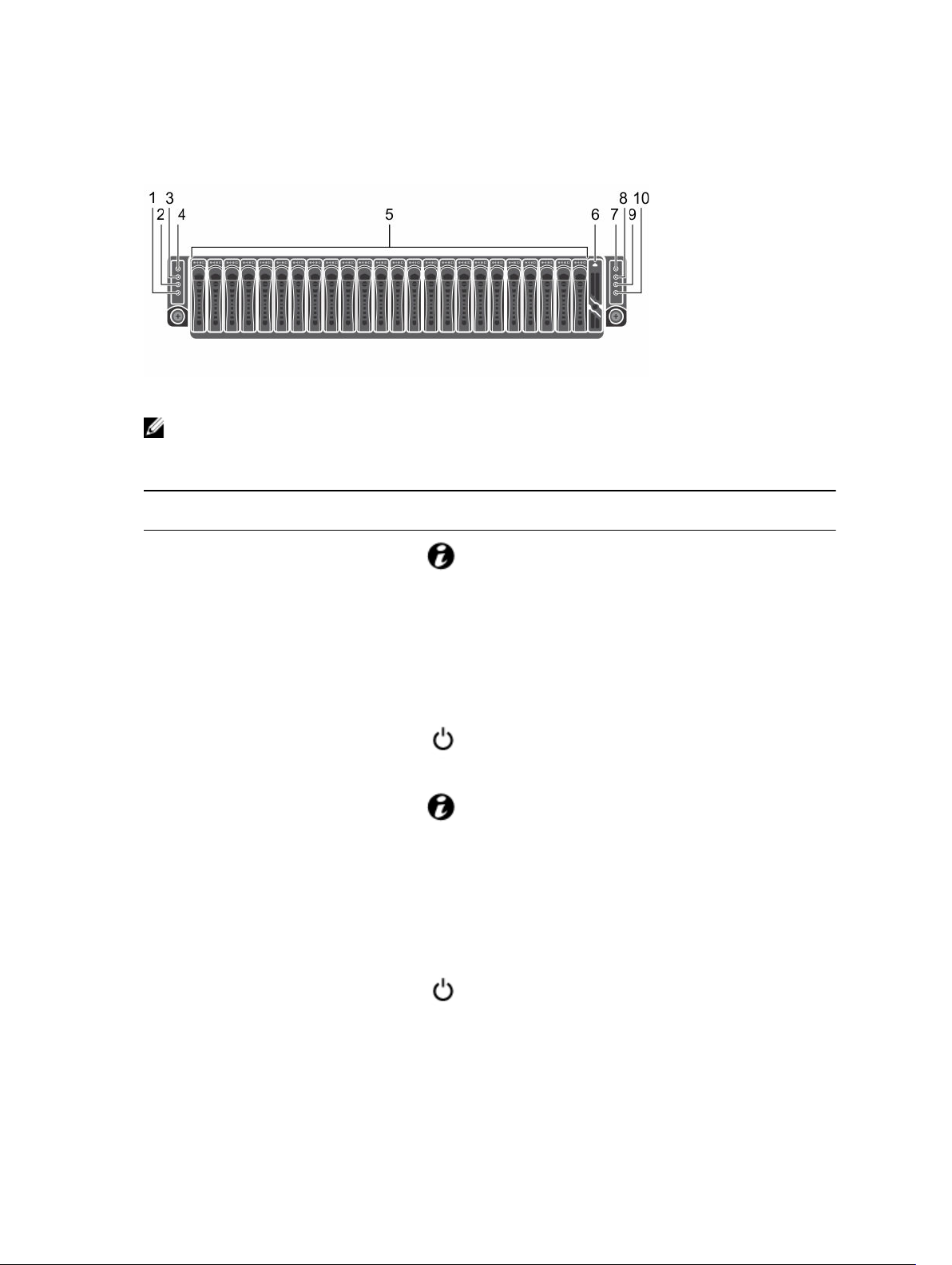
Front panel features and indicators
Figure 1. Front panel features and indicators
NOTE: For more information about the direction details of the 2.5-inch hard drive expander
configuration support, see the HDD Zoning configuration tool at Dell.com/support.
Table 1. Front-panel features and indicators
Item Indicator, button or
connector
1 System identification indicator
or button for system board 2
2 Power-on indicator or system
state indicator or power button
for system board 2
3 System identification indicator
or button for system board 1
4 Power-on indicator or system
state indicator or power button
for system board 1
Icon Description
The identification button can
be used to locate a particular
system and system board
within a chassis. When the
button is pushed, the blue
status indicator of the system
on the front and rear blinks
until the button is pushed
again.
The power-on indicator turns
to green when the system
power is on.
The identification button can
be used to locate a particular
system and system board
within a chassis. When the
button is pushed, the blue
status indicator of the system
on the front and rear blinks
until the button is pushed
again.
The power-on indicator turns
to amber when the system
critical event occurs.
5 Hard drives Up to 24, hot-swappable, 2.5--
inch hard drives.
8
Page 9

Item Indicator, button or
connector
6 Drive cover This is not a usable drive slot.
Icon Description
7 Power-on indicator or system
state indicator or power button
for system board 3
8 System identification indicator
or button for system board 3
9 Power-on indicator or system
state indicator or power button
for system board 4
NOTE: When turning on
the system, the video
monitor can take from
several seconds to over
two minutes to display an
image, depending on the
amount of DIMM installed
in the system.
NOTE: On ACPIcompliant operating
systems (OSs), turning off
the system by using the
power button causes the
system to perform a
graceful shutdown before
the system is turned off.
NOTE: To force an
ungraceful shutdown,
press and hold the power
button for five seconds.
The identification button can
be used to locate a particular
system and system board
within a chassis. When the
button is pushed, the blue
status indicator of the system
on the front and rear blinks
until the button is pushed
again.
The power button controls the
DC power supply unit (PSU)
output to the system.
10 System identification indicator
or button for system board 4
The identification button can
be used to locate a particular
system and system board
within a chassis. When the
button is pushed, the blue
status indicator of the system
on the front and rear blinks
until the button is pushed
again.
9
Page 10
Hard drive indicator patterns
Figure 2. Hard drive front view
1. hard drive status indicator (green and amber) 2. hard drive activity indicator (green)
Table 2. Hard drive indicator patterns
Controller Hard drive type Function Activity LED Status LED
Green Green
Onboard
Controller
SATA2 Drive on-line Off/Blinking when
Fail Off On
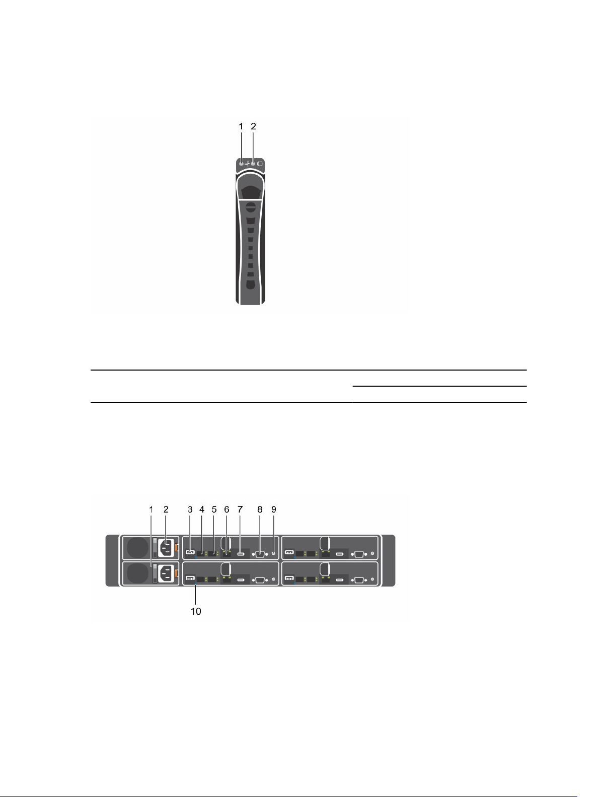
Back panel features and indicators
Figure 3. Back panel features and indicators
On
active
10
Page 11
Table 3. Back panel features and indicators
Item Indicator, button, or
Icon Description
connector
1 PSU 2 1600 W AC PSUs.
2 PSU 1 1600 W AC PSUs.
3 USB port Enables you to connect USB
devices to the system. The
ports are USB 3.0-compliant.
4 Ethernet connector 10G NIC 1 connector.
5 Ethernet connector 10G NIC 2 connector.
6 Management port Dedicated management port.
7 USB to serial port Connects the system to a host.
8 VGA port Connects a VGA display to the
system.
9 Power button/power and
system LED
The power-on indicator glows
green when the system power
is on.
The power-on indicator turns
amber when the system critical
event occurs.
The power button controls the
DC PSU output to the system.
NOTE: When turning on
the system, the video
monitor can take from
several seconds to over
two minutes to display an
image, on the basis of the
disk space available in the
system.
NOTE: On ACPIcompliant operating
systems, turning off the
system by using the
power button causes the
system to perform a
graceful shutdown before
the system is turned off.
11
Page 12
Item Indicator, button, or
connector
10 System identification indicator The management software of
Icon Description
NOTE: To force an
ungraceful shutdown,
press and hold the power
button for five seconds.
both the systems and the
identification buttons on the
front can cause the indicator
to flash blue to identify a
particular system and system
board. Indicators turn amber
when the system requires
attention because of an issue.
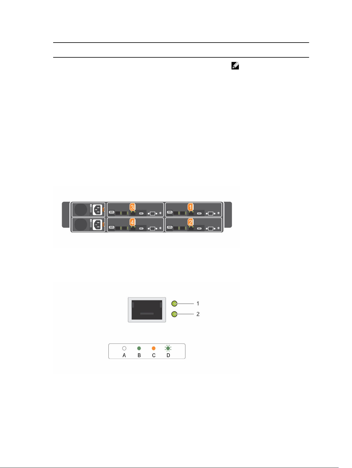
System-board assembly configurations
Figure 4. Enumeration four system boards for 1U node
LAN indicator codes
Figure 5. LAN indicators
1. activity indicator 2. link and network speed indicator
12
Page 13
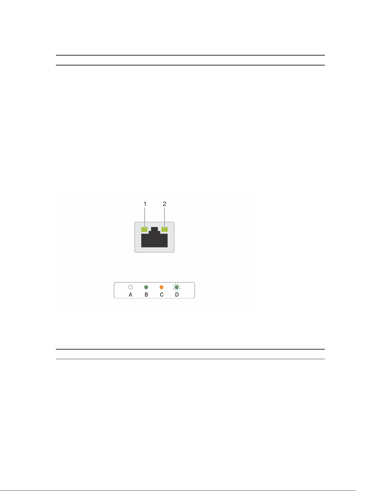
Table 4. LAN indicator codes
Component Indicator Condition
Link and network speed indicator Solid amber Linking at 1 Gbps speed
Solid green Linking at 10 Gbps speed
Activity indicator Blinking green Activity is present:
• Pre OS POST
• OS without driver
• OS with driver
Blinking at speed relative to
packet density.
Off No link/activity present
• D0 (uninitialized)
• D3 (cold)
• S4 (hibernation)
Figure 6. LAN indicators (management port)
1. speed indicator 2. link and activity indicator
Table 5. LAN indicators (management port)
Component Indicator Condition
Speed indicator Solid green Linking at 1 Gbps speed
Solid amber Linking at 10/100 Mbps speed
Link and activity indicator Off No access or Idle
Blinking green LAN access or Link up
13
Page 14

Power and system board indicator codes
The LEDs on the system front panel and back panel display status codes during system startup. For
location of the LEDs on the front panel, see the Front panel features and indicators section. For location
of the LEDs on the back panel, see the Back panel features and indicators section.
Table 6. Status indicator codes
Component Indicator Condition
Power-on indicator (A
bicolor LED on power
button)
System identification
indicator
Green Solid Power On (S0)
Amber Off
Green Off iDRAC critical condition event in Power Off mode
Amber Blinking
Green Off iDRAC critical condition event in Power On mode
Amber Blinking
Steady blue IPMI using Chassis Identify Command On or ID
Blinking blue Only IPMI using Chassis Identify Command Blink
Off IPMI using Chassis Identify Command Off or ID
(S4/S5)
(S0)
Button Press ID On
On
Button Press ID Off
14
Page 15
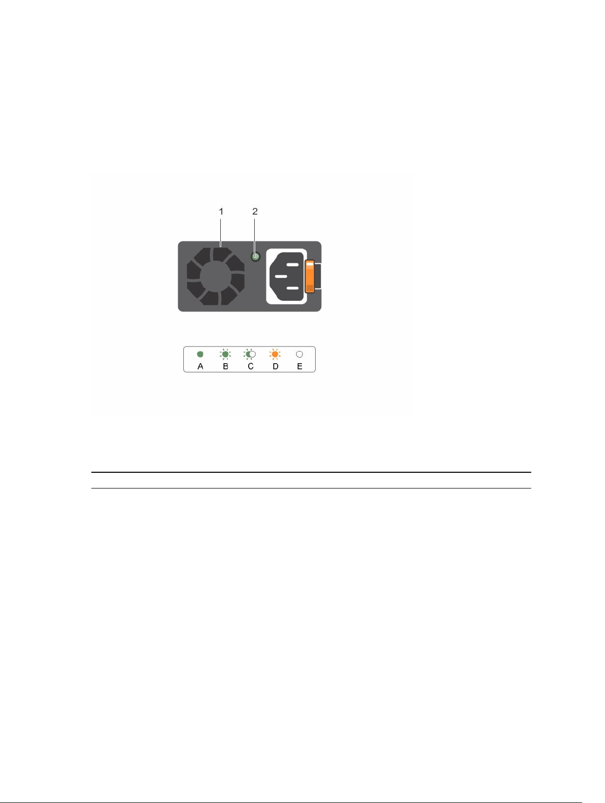
Power Supply Unit indicator codes
Each AC power supply unit (PSU) has an illuminated translucent handle that indicates whether power is
present or whether a power fault has occurred.
1600 W AC/1600 W HVDC PSU
Figure 7. PSU status indicator
1. PSU 2. AC power indicator
Table 7. 1600 W AC/1600 W HVDC PSU indicators
Component Indicator Condition
AC power indicator Solid amber
Solid green DC_OK (power good)
Blinking green Standby mode normal
Off Unit without AC power
Standby mode with Fan Lock for
15 seconds.
Standby mode with OTP range
Active mode with +12 V DC Fault
Active mode with Fan Lock for 15
seconds.
15
Page 16
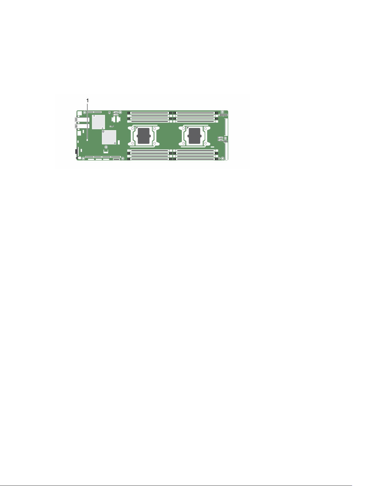
iDRAC heart beat LED
The system board provides iDRAC heart beat LED (CR17) for iDRAC debugs. The iDRAC heart beat LED is
green. When the system AC power is connected, the LED glows. When iDRAC firmware is ready, the
iDRAC heart beat LED blinks.
Figure 8. iDRAC heart beat LED on the Dell XC6320 system board
1. iDRAC heart beat LED
Documentation references
For information about the Dell documents, see the Support Matrix specific for your product.
For information about the Nutanix documents that applies to a specific release of Nutanix solution
software, see the Support Matrix specific for your product.
16
Page 17

Performing initial system configuration
After you receive your system, you must set up your system, install the operating system if it is not preinstalled, and set up and configure the system iDRAC IP address.
Setting up your system
1. Unpack the system.
2. Install the system into the rack. For more information about installing the system into the rack, see
your system Rack Installation Placemat.
3. Connect the peripheral devices to the system.
4. Connect the system to its electrical outlet.
5. Turn on the system by pressing the power button or by using iDRAC.
6. Turn on the attached peripheral devices.
Setting up and configuring the iDRAC IP address
You can set up the Integrated Dell Remote Access Controller (iDRAC) IP address by using one of the
following interfaces:
• Dell iDRAC Settings utility
• Dell Lifecycle Controller
• Dell OpenManage Deployment Toolkit
2
You can use the default iDRAC IP address 192.168.0.120 to configure the initial network settings,
including setting up DHCP or a static IP for iDRAC.
You can configure iDRAC IP address by using the following interfaces:
NOTE: Ensure that you change the default user name and password after setting up the iDRAC IP
address.
• iDRAC Web interface: For more information, see the Integrated Dell Remote Access Controller User's
Guide.
• Remote Access Controller ADMin (RACADM): For more information, see the RACADM Command Line
Interface Reference Guide and the Integrated Dell Remote Access Controller User's Guide.
• Remote Services that include Web Services Management (WS-Man): For more information, see the
Dell Lifecycle Controller Remote Services Quick Start Guide.
For more information about setting up and configuring iDRAC, see the Integrated Dell Remote Access
Controller User's Guide available at Dell.com/esmmanuals.
17
Page 18

Logging in to iDRAC
You can log in to iDRAC as an iDRAC local user, a Microsoft Active Directory user, or a Lightweight
Directory Access Protocol (LDAP) user. You can also log in by using Single Sign-On or a Smart Card. The
default user name is root and password is calvin. For more information about logging in to iDRAC and
iDRAC licenses, see the Integrated Dell Remote Access Controller User's Guide available at Dell.com/
idracmanuals.
You can also access iDRAC by using RACADM. For more information, see the RACADM Command Line
Interface Reference Guide and the Integrated Dell Remote Access Controller User's Guide available at
Dell.com/idracmanuals.
Methods of installing the operating system
If the system is shipped without an operating system, install the supported OS on the system by using one
of the following methods:
• Dell Systems Management Tools and Documentation media — see the operating system
documentation available at Dell.com/operatingsystemmanuals.
• Dell Lifecycle Controller — see the Dell Lifecycle Controller documentation available at Dell.com/
idracmanuals.
• Dell OpenManage Deployment Toolkit — see the Dell OpenManage documentation available at
Dell.com/openmanagemanuals → OpenManage software.
For information about supported operating systems, see the operating systems support matrix available at
Dell.com/ossupport.
Managing your system remotely
To perform out-of-band systems management by using iDRAC, configure iDRAC for remote accessibility,
set up the management station and managed system, and configure the supported web browsers. For
more information, see the Integrated Dell Remote Access Controller User’s Guide at Dell.com/
idracmanuals.
You can also remotely monitor and manage the server by using the Dell OpenManage Server
Administrator (OMSA) software and OpenManage Essentials (OME) systems management console. For
more information, see Dell.com/openmanagemanuals → OpenManage Server Administrator or
Dell.com/openmanagemanuals → OpenManage Essentials.
Downloading drivers and firmware
Dell recommends you to download and install the latest BIOS, drivers, and systems management
firmware on your system.
Ensure that you clear the web browser cache.
1. Go to Dell.com/support/drivers.
2. In the Identify your product section, enter the Service Tag of your system in Enter a Service Tag or
Express Service Code.
18
Page 19

NOTE: If you do not have the Service Tag, you can do one of the following:
• Select Auto-detect your product to allow the system to automatically detect your Service
Tag
• Select Browse for a product to select your product from the Select a product page.
3. Click Drivers and downloads.
The drivers that are applicable to your selection are displayed.
4. Repeat steps 1 through 3 to download the HDD zoning configuration utility.
5. Search on the basis of Category, and then click System Utilities.
HDD zoning configuration utility is displayed.
19
Page 20

Pre-operating system management applications
You can manage basic settings and features of a system without booting to the operating system by
using the system firmware.
Navigation keys
The navigation keys can help you access the pre-operating system management applications.
Page Up Moves to the previous screen.
Page Down Moves to the next screen.
Up arrow Moves to the previous field.
Down arrow Moves to the next field.
Enter Enables you to type a value in the selected field (if applicable) or follow the link in
the field.
Spacebar Expands or collapses a drop-down list, if applicable.
Tab Moves to the next focus area.
3
NOTE: This feature is applicable for the standard graphical browser only.
Esc Moves to the previous page until you view the main screen. Pressing Esc in the
main screen exits System BIOS/iDRAC Settings/Device Settings/Service Tag
Settings and proceeds with system boot.
F1 Displays the System Setup help information.
F2 Enables you to enter System Setup.
F10 Enables you to enter Lifecycle Controller.
F11 Enables you to enter Boot Manager.
F12 Enables you to enter PXE boot.
System Setup
By using the System Setup screen, you can configure the BIOS settings, iDRAC settings, and device
settings of your system.
These settings have already been preconfigured per solution requirements. Contact Dell before you
change these settings.
20
Page 21

NOTE: Help text for the selected field is displayed in the graphical browser by default. To view the
help text in the text browser, press F1.
You can access system setup by using two methods:
• Standard graphical browser—The browser is enabled by default.
• Text browser—The browser is enabled by using Console Redirection.
Entering System Setup
1. Turn on, or restart your system.
2. Press F2 immediately after you see the following message:
F2 = System Setup
If your operating system begins to load before you press F2, wait for the system to finish booting,
and then restart your system and try again.
System Setup details
The System Setup Main Menu screen details are explained as follows:
System BIOS Enables you to configure BIOS settings.
iDRAC Settings Enables you to configure iDRAC settings.
The iDRAC settings utility is an interface to set up and configure the iDRAC
parameters by using UEFI (Unified Extensible Firmware Interface). You can enable
or disable various iDRAC parameters by using the iDRAC settings utility. For more
information about this utility, see Integrated Dell Remote Access Controller User’s
Guide at Dell.com/idracmanuals.
Device Settings Enables you to configure device settings.
System BIOS Settings details
The System BIOS Settings screen details are explained as follows:
System
Information
Memory Settings Specifies information and options related to the installed memory.
Processor Settings Specifies information and options related to the processor such as speed and
SATA Settings Specifies options to enable or disable the integrated SATA controller and ports.
Boot Settings Specifies options to specify the boot mode (BIOS or UEFI). Enables you to modify
Network Settings Specifies options to change the network settings.
Integrated
Devices
Specifies information about the system such as the system model name, BIOS
version, and Service Tag.
cache size.
UEFI and BIOS boot settings.
Specifies options to manage integrated device controllers and ports and specify
related features and options.
21
Page 22

Serial
Communication
System Profile
Settings
System Security Specifies options to configure the system security settings, such as system
Miscellaneous
Settings
Specifies options to manage the serial ports and specify related features and
options.
Specifies options to change the processor power management settings, memory
frequency, and so on.
password, setup password, Trusted Platform Module (TPM) security. It also
manages the power and NMI buttons on the system.
Specifies options to change the system date, time, and so on.
System Information details
The System Information screen details are explained as follows:
System Model
Name
System BIOS
Version
System
Management
Engine Version
System Service
Tag
System
Manufacturer
System
Manufacturer
Contact
Information
System CPLD
Version
UEFI Compliance
Version
Specifies the system model name.
Specifies the BIOS version installed on the system.
Specifies the current version of the Management Engine firmware.
Specifies the system Service Tag.
Specifies the name of the system manufacturer.
Specifies the contact information of the system manufacturer.
Specifies the current version of the system complex programmable logic device
(CPLD) firmware.
Specifies the UEFI compliance level of the system firmware.
Memory Settings details
The Memory Settings screen details are explained as follows:
System Memory
Size
System Memory
Type
System Memory
Speed
System Memory
Voltage
Video Memory Specifies the amount of video memory.
22
Specifies the memory size in the system.
Specifies the type of memory installed in the system.
Specifies the system memory speed.
Specifies the system memory voltage.
Page 23

System Memory
Testing
Memory
Operating Mode
Node Interleaving Specifies if Non-Uniform Memory architecture (NUMA) is supported. If this field is
Snoop Mode Specifies the Snoop Mode options. The Snoop Mode options available are Home
Specifies whether the system memory tests are run during system boot. Options
are Enabled and Disabled. This option is set to Disabled by default.
Specifies the memory operating mode. The options available are Optimizer Mode,
Advanced ECC Mode, Mirror Mode, Spare Mode, Spare with Advanced ECC Mode,
Dell Fault Resilient Mode and Dell NUMA Fault Resilient Mode. This option is set
to Optimizer Mode by default.
NOTE: The Memory Operating Mode option can have different default and
available options based on the memory configuration of your system.
NOTE: The Dell Fault Resilient Mode option establishes an area of memory
that is fault resilient. This mode can be used by an operating system that
supports the feature to load critical applications or enables the operating
system kernel to maximize system availability.
set to Enabled, memory interleaving is supported if a symmetric memory
configuration is installed. If the field is set to Disabled, the system supports NUMA
(asymmetric) memory configurations. This option is set to Disabled by default.
Snoop, Early Snoop, and Cluster on Die. This option is set to Early Snoop by
default. This field is available only when the Node Interleaving is set to Disabled.
Processor Settings details
The Processor Settings screen details are explained as follows:
Logical Processor
QPI Speed Enables you to control QuickPath Interconnect data rate settings.
Alternate RTID
(Requestor
Transaction ID)
Setting
Virtualization
Technology
Address
Translation
Service (ATS)
Adjacent Cache
Line Prefetch
Hardware
Prefetcher
DCU Streamer
Prefetcher
Enables or disables the logical processors and displays the number of logical
processors. If this option is set to Enabled, the BIOS displays all the logical
processors. If this option is set to Disabled, the BIOS displays only one logical
processor per core. This option is set to Enabled by default.
Modifies Requestor Transaction IDs, which are QPI resources. This option is set to
Disabled by default.
NOTE: Enabling this option may negatively impact the overall system
performance.
Enables or disables the additional hardware capabilities provided for virtualization.
This option is set to Enabled by default.
Defines the Address Translation Cache (ATC) for devices to cache the DMA
transactions. This option provides an interface between CPU and DMA Memory
Management to a chipset's Address Translation and Protection Table to translate
DMA addresses to host addresses. This option is set to Enabled by default.
Optimizes the system for applications that need high utilization of sequential
memory access. This option is set to Enabled by default. You can disable this
option for applications that need high utilization of random memory access.
Enables or disables the hardware prefetcher. This option is set to Enabled by
default.
Enables or disables the Data Cache Unit (DCU) streamer prefetcher. This option is
set to Enabled by default.
23
Page 24

DCU IP Prefetcher Enables or disables the Data Cache Unit (DCU) IP prefetcher. This option is set to
Enabled by default.
Execute Disable Enables you to run the disable memory protection technology. This option is set to
Enabled by default.
Logical Processor
Idling
Configurable TDP Enables you to reconfigure the processor Thermal Design Power (TDP) levels
X2Apic Mode Enables or disables the X2Apic mode.
Dell Controlled
Turbo
Enables you to improve the energy efficiency of a system. It uses the operating
system core parking algorithm and parks some of the logical processors in the
system which in turn allows the corresponding processor cores to transition into a
lower power idle state. This option can only be enabled if the operating system
supports it. It is set to
during POST based on the power and thermal delivery capabilities of the system.
TDP verifies the maximum heat the cooling system is needed to dissipate. This
option is set to Nominal by default.
NOTE: This option is only available on certain stock keeping units (SKUs) of the
processors.
Controls the turbo engagement. Enable this option only when System Profile is set
to Performance.
NOTE: Depending on the number of installed CPUs, there may be up to four
processor listings.
Disabled by default.
Number of Cores
per Processor
Processor 64-bit
Support
Processor Core
Speed
Processor 1
Controls the number of enabled cores in each processor. This option is set to All
by default.
Specifies if the processor(s) support 64-bit extensions.
Specifies the maximum core frequency of the processor.
NOTE: Depending on the number of CPUs, there may be up to four
processors listed.
The following settings are displayed for each processor installed in the system:
Family-ModelStepping
Brand Specifies the brand name.
Level 2 Cache Specifies the total L2 cache.
Level 3 Cache Specifies the total L3 cache.
Number of Cores Specifies the number of cores per processor.
Specifies the family, model, and stepping of the processor
as defined by Intel.
SATA Settings details
The SATA Settings screen details are explained as follows:
Embedded SATA
24
Enables the embedded SATA option to be set to Off, ATA, AHCI, or RAID modes.
This option is set to AHCI by default.
Page 25

Security Freeze
Lock
Write Cache Enables or disables the command for Embedded SATA drives during POST.
Port A Sets the drive type of the selected device. For Embedded SATA settings in ATA
Port B Sets the drive type of the selected device. For Embedded SATA settings in ATA
Sends Security Freeze Lock command to the Embedded SATA drives during POST.
This option is applicable only for ATA and AHCI modes.
mode, set this field to Auto to enable BIOS support. Set it to OFF to turn off BIOS
support.
For AHCI or RAID mode, BIOS support is always enabled.
Model Specifies the drive model of the selected device.
Drive Type Specifies the type of drive attached to the SATA port.
Capacity Specifies the total capacity of the hard drive. This field is
undefined for removable media devices such as optical
drives.
Port C Sets the drive type of the selected device. For Embedded SATA settings in ATA
mode, set this field to Auto to enable BIOS support. Set it to OFF to turn off BIOS
support.
For AHCI or RAID mode, BIOS support is always enabled.
Model Specifies the drive model of the selected device.
Drive Type Specifies the type of drive attached to the SATA port.
Capacity Specifies the total capacity of the hard drive. This field is
undefined for removable media devices such as optical
drives.
Port D Sets the drive type of the selected device. For Embedded SATA settings in ATA
mode, set this field to Auto to enable BIOS support. Set it to OFF to turn off BIOS
support.
For AHCI or RAID mode, BIOS support is always enabled.
Port E Sets the drive type of the selected device. For Embedded SATA settings in ATA
mode, set this field to Auto to enable BIOS support. Set it to OFF to turn off BIOS
support.
For AHCI or RAID mode, BIOS support is always enabled.
25
Page 26

Port F Sets the drive type of the selected device. For Embedded SATA settings in ATA
mode, set this field to Auto to enable BIOS support. Set it to OFF to turn off BIOS
support.
For AHCI or RAID mode, BIOS support is always enabled.
Port G Sets the drive type of the selected device. For Embedded SATA settings in ATA
mode, set this field to Auto to enable BIOS support. Set it to OFF to turn off BIOS
support.
For AHCI or RAID mode, BIOS support is always enabled.
Model Specifies the drive model of the selected device.
Drive Type Specifies the type of drive attached to the SATA port.
Capacity Specifies the total capacity of the hard drive. This field is
undefined for removable media devices such as optical
drives.
Port H Sets the drive type of the selected device. For Embedded SATA settings in ATA
mode, set this field to Auto to enable BIOS support. Set it to OFF to turn off BIOS
support.
For AHCI or RAID mode, BIOS support is always enabled.
Model Specifies the drive model of the selected device.
Drive Type Specifies the type of drive attached to the SATA port.
Capacity Specifies the total capacity of the hard drive. This field is
undefined for removable media devices such as optical
drives.
Port I Sets the drive type of the selected device. For Embedded SATA settings in ATA
mode, set this field to Auto to enable BIOS support. Set it to OFF to turn off BIOS
support.
For AHCI or RAID mode, BIOS support is always enabled.
Model Specifies the drive model of the selected device.
Drive Type Specifies the type of drive attached to the SATA port.
Capacity Specifies the total capacity of the hard drive. This field is
undefined for removable media devices such as optical
drives.
Port J Sets the drive type of the selected device. For Embedded SATA settings in ATA
mode, set this field to Auto to enable BIOS support. Set it to OFF to turn off BIOS
support.
For AHCI or RAID mode, BIOS support is always enabled.
Model Specifies the drive model of the selected device.
Drive Type Specifies the type of drive attached to the SATA port.
26
Page 27

Capacity Specifies the total capacity of the hard drive. This field is
undefined for removable media devices such as optical
drives.
Boot Settings details
The Boot Settings screen details are explained as follows:
Boot Mode Enables you to set the boot mode of the system.
CAUTION: Switching the boot mode may prevent the system from booting if
the operating system is not installed in the same boot mode.
If the operating system supports UEFI, you can set this option to UEFI. Setting this
field to BIOS allows compatibility with non-UEFI operating systems. This option is
set to BIOS by default.
NOTE: Setting this field to UEFI disables the BIOS Boot Settings menu. Setting
this field to
BIOS disables the UEFI Boot Settings menu.
Boot Sequence
Retry
Hard-Disk Failover Specifies the hard drive that is booted in the event of a hard drive failure. The
Boot Option
Settings
BIOS Boot
Settings
UEFI Boot Settings Enables or disables UEFI Boot options. The Boot options include IPv4 PXE and IPv6
Enables or disables the Boot Sequence Retry feature. If this option is set to Enabled
and the system fails to boot, the system reattempts the boot sequence after 30
seconds. This option is set to Enabled by default.
devices are selected in the Hard-Disk Drive Sequence on the Boot Option Setting
menu. When this option is set to Disabled, only the first hard drive in the list is
attempted to boot. When this option is set to Enabled, all hard drives are attempted
to boot in the order selected in the
enabled for UEFI Boot Mode.
Configures the boot sequence and the boot devices.
Enables or disables BIOS boot options.
NOTE: This option is enabled only if the boot mode is BIOS.
PXE. This option is set to IPv4 by default.
NOTE: This option is enabled only if the boot mode is UEFI.
Hard-Disk Drive Sequence. This option is not
Network Settings screen details
The Network Settings screen details are explained as follows:
PXE Device n
1 to 4)
PXE Device n
Settings (n = 1 to
4)
(n =
Enables or disables the device. When enabled, a UEFI boot option is created for the
device.
Enables you to control the configuration of the PXE device.
Integrated Devices details
The Integrated Devices screen details are explained as follows:
27
Page 28

USB 3.0 Setting Enables or disables the USB 3.0 support. Enable this option only if your operating
system supports USB 3.0. If you disable this option, devices operate at USB 2.0
speed. USB 3.0 is enabled by default.
User Accessible
USB Ports
Internal USB Port Enables or disables the internal USB port. This option is set to Enabled by default.
Integrated RAID
Controller
Integrated
Network Card 1
Embedded NIC1
and NIC2
I/OAT DMA Engine Enables or disables the I/OAT option. Enable only if the hardware and software
Embedded Video
Controller
Current State of
Embedded Video
Controller
SR-IOV Global
Enable
OS Watchdog
Timer
Memory Mapped
I/O above 4 GB
Slot Disablement Enables or disables the available PCIe slots on your system. The slot disablement
Enables or disables the USB ports. Selecting Only Back Ports On disables the front
USB ports, selecting All Ports Off disables all USB ports. The USB keyboard and
mouse operate during boot process in certain operating systems. After the boot
process is complete, the USB keyboard and mouse do not work if the ports are
disabled.
NOTE: Selecting Only Back Ports On and All Ports Off disables the USB
management port and also restricts access to iDRAC features.
Enables or disables the integrated RAID controller. This option is set to Enabled by
default.
Enables or disables the integrated network card.
NOTE: The Embedded NIC1 and NIC2 options are only available on systems
that do not have Integrated Network Card 1.
Enables or disables the Embedded NIC1 and NIC2 options. If set to Disabled, the
NIC may still be available for shared network access by the embedded
management controller. The embedded NIC1 and NIC2 options are only available
on systems that do not have Network Daughter Cards (NDCs). The Embedded NIC1
and NIC2 option is mutually exclusive with the Integrated Network Card 1 option.
Configure the Embedded NIC1 and NIC2 option by using the NIC management
utilities of the system.
support the feature.
Enables or disables the Embedded Video Controller option. This option is set to
Enabled by default.
Displays the current state of the embedded video controller. The Current State of
Embedded Video Controller option is a read-only field. If the Embedded Video
Controller is the only display capability in the system (that is, no add-in graphics
card is installed), then the Embedded Video Controller is automatically used as the
primary display even if the
Enables or disables the BIOS configuration of Single Root I/O Virtualization (SRIOV) devices. This option is set to Enabled by default.
If your system stops responding, this watchdog timer aids in the recovery of your
operating system. When this option is set to Enabled, the operating system
initializes the timer. When this option is set to Disabled (the default), the timer does
not have any effect on the system.
Enables or disables the support for PCIe devices that need large amounts of
memory. This option is set to Enabled by default.
feature controls the configuration of PCIe cards installed in the specified slot. Slots
must be disabled only when the installed peripheral card prevents booting into the
operating system or causes delays in system startup. If the slot is disabled, both the
Option ROM and UEFI drivers are disabled.
Embedded Video Controller setting is set to Disabled.
28
Page 29

Serial Communication details
The Serial Communication screen details are explained as follows:
Serial
Communication
Serial Port
Address
External Serial
Connector
Selects serial communication devices (Serial Device 1 and Serial Device 2) in BIOS.
BIOS console redirection can also be enabled and the port address can be
specified. This option is set to Auto by default.
Enables you to set the port address for serial devices. This option is set to Serial
Device 1=COM2, Serial Device 2=COM1 by default.
NOTE: You can use only Serial Device 2 for the Serial Over LAN (SOL) feature.
To use console redirection by SOL, configure the same port address for
console redirection and the serial device.
NOTE: Every time the system boots, the BIOS syncs the serial MUX setting
saved in iDRAC. The serial MUX setting can independently be changed in
iDRAC. Loading the BIOS default settings from within the BIOS setup utility
may not always revert the serial MUX setting to the default setting of Serial
Device 1.
Enables you to associate the External Serial Connector to Serial Device 1, Serial
Device 2, or the Remote Access Device by using this option.
NOTE: Only Serial Device 2 can be used for Serial Over LAN (SOL). To use
console redirection by SOL, configure the same port address for console
redirection and the serial device.
NOTE: Every time the system boots, the BIOS syncs the serial MUX setting
saved in iDRAC. The serial MUX setting can independently be changed in
iDRAC. Loading the BIOS default settings from within the BIOS setup utility
may not always revert this setting to the default setting of Serial Device 1.
Failsafe Baud Rate Specifies the failsafe baud rate for console redirection. The BIOS attempts to
determine the baud rate automatically. This failsafe baud rate is used only if the
attempt fails, and the value must not be changed. This option is set to 115200 by
default.
Remote Terminal
Type
Redirection After
Boot
Sets the remote console terminal type. This option is set to VT 100/VT 220 by
default.
Enables or disables the BIOS console redirection when the operating system is
loaded. This option is set to Enabled by default.
System Profile Settings details
The System Profile Settings screen details are explained as follows:
System Profile
Sets the system profile. If you set the System Profile option to a mode other than
Custom, the BIOS automatically sets the rest of the options. You can only change
the rest of the options if the mode is set to Custom. This option is set to
Performance Per Watt Optimized (DAPC) by default. DAPC is Dell Active Power
Controller.
NOTE: All the parameters on the system profile setting screen are available
only when the System Profile option is set to Custom.
29
Page 30

CPU Power
Management
Memory
Frequency
Turbo Boost Enables or disables the processor to operate in the turbo boost mode. This option
Energy Efficient
Turbo
C1E Enables or disables the processor to switch to a minimum performance state when
C States Enables or disables the processor to operate in all available power states. This
Collaborative CPU
Performance
Control
Memory Patrol
Scrub
Memory Refresh
Rate
Uncore Frequency Enables you to select the Processor Uncore Frequency option.
Sets the CPU power management. This option is set to System DBPM (DAPC) by
default. DBPM is Demand-Based Power Management.
Sets the speed of the system memory. You can select Maximum Performance,
Maximum Reliability, or a specific speed.
is set to Enabled by default.
Enables or disables the Energy Efficient Turbo option.
Energy Efficient Turbo (EET) is a mode of operation where a processor’s core
frequency is adjusted to be within the turbo range based on workload.
it is idle. This option is set to Enabled by default.
option is set to Enabled by default.
Enables or disables the CPU power management option. When set to Enabled, the
CPU power management is controlled by the OS DBPM and the System DBPM
(DAPC). This option is set to Disabled by default.
Sets the memory patrol scrub frequency. This option is set to Standard by default.
Sets the memory refresh rate to either 1x or 2x. This option is set to 1x by default.
Dynamic mode enables the processor to optimize power resources across the
cores and uncore during runtime. The optimization of the uncore frequency to
either save power or optimize performance is influenced by the setting of the
Energy Efficiency Policy option.
Energy Efficient
Policy
Number of Turbo
Boot Enabled
Cores for
Processor 1
Monitor/Mwait Enables the Monitor/Mwait instructions in the processor. This option is set to
Enables you to select the Energy Efficient Policy option.
The CPU uses the setting to manipulate the internal behavior of the processor and
determines whether to target higher performance or better power savings.
NOTE: If there are two processors installed in the system, you see an entry for
Number of Turbo Boost Enabled Cores for Processor 2.
Controls the number of turbo boost enabled cores for processor 1. The maximum
number of cores is enabled by default.
Enabled for all system profiles, except Custom by default.
NOTE: This option can be disabled only if the C States option in the Custom
mode is set to disabled.
NOTE: When C States is set to Enabled in the Custom mode, changing the
Monitor/Mwait setting does not impact the system power or performance.
System Security Settings details
The System Security Settings screen details are explained as follows:
30
Page 31

Intel AES-NI Improves the speed of applications by performing encryption and decryption by
using the Advanced Encryption Standard Instruction Set (AES-NI). This option is set
to Enabled by default.
System Password Sets the system password. This option is set to Enabled by default and is read-only
if the password jumper is not installed in the system.
Setup Password Sets the setup password. This option is read-only if the password jumper is not
installed in the system.
Password Status Locks the system password. This option is set to Unlocked by default.
TPM Security
TPM Information Changes the operational state of the TPM. This option is set to No Change by
TPM Status Specifies the TPM status.
TPM Command
Intel TXT Enables or disables the Intel Trusted Execution Technology (TXT) option. To enable
Power Button Enables or disables the power button on the front of the system. This option is set
NMI Button Enables or disables the NMI button on the front of the system. This option is set to
AC Power
Recovery
AC Power
Recovery Delay
User Defined
Delay (60s to
240s)
UEFI Variable
Access
Secure Boot Enables Secure Boot, where the BIOS authenticates each pre-boot image by using
Secure Boot
Policy
NOTE: The TPM menu is available only when the TPM module is installed.
Enables you to control the reporting mode of the TPM. The TPM Security option is
set to Off by default. You can only modify the TPM Status, TPM Activation, and Intel
TXT fields if the TPM Status field is set to either On with Pre-boot Measurements
or On without Pre-boot Measurements.
default.
CAUTION: Clearing the TPM results in the loss of all keys in the TPM. The
loss of TPM keys may affect booting to the operating system.
Clears all the contents of the TPM. The TPM Clear option is set to No by default.
the Intel TXT option, virtualization technology and TPM Security must be enabled
with Pre-boot measurements. This option is set to Off by default.
to Enabled by default.
Disabled by default.
Sets how the system behaves after AC power is restored to the system. This option
is set to Last by default.
Sets the time delay for the system to power up after AC power is restored to the
system. This option is set to Immediate by default.
Sets the User Defined Delay option when the User Defined option for AC Power
Recovery Delay is selected.
Provides varying degrees of securing UEFI variables. When set to Standard (the
default), UEFI variables are accessible in the operating system per the UEFI
specification. When set to Controlled, selected UEFI variables are protected in the
environment and new UEFI boot entries are forced to be at the end of the current
boot order.
the certificates in the Secure Boot Policy. Secure Boot is disabled by default.
When Secure Boot policy is set to Standard, the BIOS uses the system
manufacturer’s key and certificates to authenticate pre-boot images. When Secure
Boot policy is set to Custom, the BIOS uses the user-defined key and certificates.
Secure Boot policy is set to Standard by default.
31
Page 32

Secure Boot
Policy Summary
Specifies the list of certificates and hashes that secure boot uses to authenticate
images.
Miscellaneous Settings details
The Miscellaneous Settings screen details are explained as follows:
System Time Enables you to set the time on the system.
System Date Enables you to set the date on the system.
Asset Tag Specifies the asset tag and enables you to modify it for security and tracking
purposes.
Keyboard
NumLock
Enables you to set whether the system boots with the NumLock enabled or
disabled. This option is set to On by default.
NOTE: This option does not apply to 84-key keyboards.
F1/F2 Prompt on
Error
Load Legacy
Video Option
ROM
In-System
Characterization
Enables or disables the F1/F2 prompt on error. This option is set to Enabled by
default. The F1/F2 prompt also includes keyboard errors.
Enables you to determine whether the system BIOS loads the legacy video (INT
10H) option ROM from the video controller. Selecting Enabled in the operating
system does not support UEFI video output standards. This field is available only for
UEFI boot mode. You cannot set the option to Enabled if UEFI Secure Boot mode
is enabled.
Enables or disables In-System Characterization. This option is set to Disabled by
default. The two other options are Enabled and Enabled - No Reboot.
NOTE: The default setting for In-System Characterization is subject to change
in future BIOS releases.
When enabled, In-System Characterization (ISC) executes during POST upon
detecting relevant change(s) in system configuration to optimize system power and
performance. ISC takes about 20 seconds to execute, and system reset is needed
for ISC results to be applied. The Enabled - No Reboot option executes ISC and
continues without applying ISC results until the next time system reset occurs. The
Enabled option executes ISC and forces an immediate system reset so that ISC
results can be applied. It takes the system longer to be ready due to the forced
system reset. When disabled, ISC does not execute.
System setup options at boot
F2 Initiate Setup during POST
Alt+F Load optimal default properties in Setup menu.
32
Page 33

About Boot Manager
Boot manager enables you to add, delete, and arrange boot options. You can also access System Setup
and boot options without restarting the system.
Viewing Boot Manager
To enter Boot Manager:
1. Turn on, or restart your system.
2. Press F11 when you see the following message:
F11 = Boot Manager
If your operating system begins to load before you press F11, allow the system to complete the
booting, and then restart your system and try again.
Boot Manager main menu
Continue Normal
Boot
One Shot Boot
Menu
Launch System
Setup
Launch Lifecycle
Controller
System Utilities Opens system utilities menu such as system diagnostics and UEFI shell.
The system attempts to boot to devices starting with the first item in the boot
order. If the boot attempt fails, the system continues with the next item in the boot
order until the boot is successful or no more boot options are found.
Displays the boot menu where you can select a one time boot device to boot from.
Allows you to access the System Setup.
Closes the Boot Manager and invokes the Dell Lifecycle Controller program.
Changing the boot order
You may have to change the boot order if you want to boot from a USB key or an optical drive. The
following instructions may vary if you have selected BIOS for Boot Mode.
1. On the System Setup Main Menu screen, click System BIOS → Boot Settings.
2. Click Boot Option Settings → Boot Sequence.
3. Use the arrow keys to select a boot device, and use the plus (+) and minus (-) sign keys to move the
device down or up in the order.
4. Click Exit, and then click Yes to save the settings on exit.
Choosing the system boot mode
System Setup enables you to specify one of the following boot modes for installing your operating
system:
• BIOS boot mode (the default) is the standard BIOS-level boot interface.
• Unified Extensible Firmware Interface (UEFI) boot mode is an enhanced 64-bit boot interface. If you
have configured your system to boot to UEFI mode, it replaces the system BIOS.
33
Page 34

1. From the System Setup Main Menu, click Boot Settings, and select Boot Mode.
2. Select the boot mode you want the system to boot into.
CAUTION: Switching the boot mode may prevent the system from booting if the operating
system is not installed in the same boot mode.
3. After the system boots in the specified boot mode, proceed to install your operating system from
that mode.
NOTE: Operating systems must be UEFI-compatible to be installed from the UEFI boot mode. DOS
and 32-bit operating systems do not support UEFI and can only be installed from the BIOS boot
mode.
NOTE: For the latest information about supported operating systems, go to Dell.com/ossupport.
Assigning a system and setup password
NOTE: The password jumper enables or disables the System Password and Setup Password
features. For more information about the password jumper settings, see Dell XC6320 system board
connectors.
You can assign a new System Password and Setup Password or change an existing System Password
and Setup Password only when the password jumper setting is Enabled and Password Status is
Unlocked. If the password jumper setting is disabled, the existing System Password and Setup Password
are deleted and you need not provide the system password to boot the system.
1. To enter System Setup, press F2 immediately after a power-on or reboot.
2. From the System Setup Main Menu, select System BIOS and press Enter.
3. On the System BIOS screen, select System Security and press Enter.
4. On the System Security screen, ensure that password status is unlocked.
5. Select System Password, enter your system password, and press Enter or Tab.
Use the following guidelines to assign the system password:
• A password can have up to 32 characters.
• The password can contain the numbers 0 through 9.
• Only the following special characters are allowed: space, (”), (+), (,), (-), (.), (/), (;), ([), (\), (]), (`).
A message prompts you to re-enter the system password.
6. Re-enter the system password, and then click OK.
7. Select Setup Password, enter your system password and press Enter or Tab.
A message prompts you to re-enter the setup password.
8. Re-enter the setup password, and click OK.
9. Press Esc to return to the System BIOS screen. Press Esc.
A message prompts you to save the changes.
NOTE: Password protection does not take effect until the system reboots.
34
Page 35

Deleting or changing system and setup password
NOTE: You cannot delete or change an existing system or setup password if the Password Status is
set to Locked.
1. To enter System Setup, press F2 immediately after turning on or restarting your system.
2. On the System Setup Main Menu screen, click System BIOS → System Security.
3. On the System Security screen, ensure that Password Status is set to Unlocked.
4. In the System Password field, alter or delete the existing system password, and then press Enter or
Tab.
5. In the Setup Password field, alter or delete the existing setup password, and then press Enter or Tab.
If you change the system and setup password, a message prompts you to reenter the new password.
If you delete the system and setup password, a message prompts you to confirm the deletion.
6. Press Esc to return to the System BIOS screen. Press Esc again, and a message prompts you to save
the changes.
35
Page 36

Installing and removing system components
Safety instructions
WARNING: Whenever you lift the system, get others to assist you. To avoid injury, do not attempt
to lift the system by yourself.
WARNING: Working on systems that are still connected to a PSU can be dangerous.
CAUTION: This system must be operated with the system cover installed to ensure proper
cooling.
CAUTION: System components and electronic circuit boards can be damaged by discharge of
static electricity.
CAUTION: Many repairs may only be done by a certified service technician. You should only
perform troubleshooting and simple repairs as authorized in your product documentation, or as
directed by the online or telephone service and support team. Damage due to servicing that is
not authorized by Dell is not covered by your warranty. Read and follow the safety instructions
that are shipped with your product.
To avoid injury to yourself or damage to the system, follow these guidelines:
4
• Always disconnect the system from the power outlet whenever you are working inside the system.
• If possible, wear a grounded wrist strap as you work inside the system. Or discharge any static
electricity by touching the bare metal chassis of system case, or the bare metal body of any other
grounded appliance.
• Hold electronic circuit boards by the edges only. Do not touch the components on the board unless it
is necessary to do so. Do not flex or stress the circuit board.
• Leave all components inside the static-proof packaging until you are ready to use the component for
the installation.
Recommended tools
• #1 Phillips screwdriver
• #2 Phillips screwdriver
• Torx #T20 screwdriver
36
Page 37

Opening and closing the system
CAUTION: Many repairs may only be done by a certified service technician. You should only
perform troubleshooting and simple repairs as authorized in your product documentation, or as
directed by the online or telephone service and support team. Damage due to servicing that is
not authorized by Dell is not covered by your warranty. Read and follow the safety instructions
that are shipped with your product.
Removing the system cover
CAUTION: Many repairs may only be done by a certified service technician. You should only
perform troubleshooting and simple repairs as authorized in your product documentation, or as
directed by the online or telephone service and support team. Damage due to servicing that is
not authorized by Dell is not covered by your warranty. Read and follow the safety instructions
that are shipped with your product.
1. Follow the safety guidelines listed in the Safety instructions section.
2. Turn off the system, including any attached peripherals.
3. Disconnect the system from the electrical outlet and disconnect the peripherals.
1. Remove the securing screw from the system cover.
2. Press the cover release latch lock.
3. Hold the system cover on both the sides with your palm on the traction pad, and slide out the system
cover.
4. Lift the cover away from the system.
Figure 9. Opening and closing the system
1. system cover 2. securing screw
3. traction pad 4. cover release latch lock
Install the system cover.
37
Page 38

Installing the system cover
CAUTION: Many repairs may only be done by a certified service technician. You should only
perform troubleshooting and simple repairs as authorized in your product documentation, or as
directed by the online or telephone service and support team. Damage due to servicing that is
not authorized by Dell is not covered by your warranty. Read and follow the safety instructions
that are shipped with your product.
Follow the safety guidelines listed in the Safety instructions section.
1. Place the system cover on the chassis and slide it to the front of the chassis until it snaps into place.
2. Secure the cover with the securing screw.
1. Reconnect the system to the electrical outlet.
2. Turn on the system, including any attached peripherals.
Inside the system
CAUTION: Many repairs may only be done by a certified service technician. You should only
perform troubleshooting and simple repairs as authorized in your product documentation, or as
directed by the online or telephone service and support team. Damage due to servicing that is
not authorized by Dell is not covered by your warranty. Read and follow the safety instructions
that are shipped with your product.
CAUTION: This system must be operated with the system cover installed to ensure proper
cooling.
Cooling fans
Servers use a lot of power to function, and that in turn generates a lot of heat. That heat, without a
system in place to dissipate it, can destroy the mechanical parts and damage the server. In most cases,
the simplest and most efficient way to dissipate this heat is through the use of fans.
Removing a cooling fan
WARNING: Do not attempt to operate the system without the cooling fans.
WARNING: The cooling fan can continue to spin for some time after the system has been
powered down. Allow time for the fan to stop spinning before removing it from the system.
CAUTION: Many repairs may only be done by a certified service technician. You should only
perform troubleshooting and simple repairs as authorized in your product documentation, or as
directed by the online or telephone service and support team. Damage due to servicing that is
not authorized by Dell is not covered by your warranty. Read and follow the safety instructions
that are shipped with your product.
NOTE: Observe the routing of the cable through the cable tie as you remove them from the system.
You must route these cables properly when you replace them to prevent the cables from being
pinched or crimped.
1. Follow the safety guidelines listed in the Safety instructions section.
38
Page 39

2. Follow the procedure listed in the Before working inside your system section.
1. Disconnect the fan’s power cable from the power distribution board 1.
2. Lift the cooling fan cage out of the chassis.
Figure 10. Removing and installing a cooling fan cage
1. locking clips (2) 2. cooling fan cage
3. power connector 4. locating pin (6)
3. Disconnect the fan cable from the fan connector on the cooling fan cage.
4. Lift the cooling fan with the sponge out of the cooling fan cage.
39
Page 40

Figure 11. Removing and installing a cooling fan
1. cooling fan 1 2. cooling fan 2
3. cooling fan 3 4. sponge
5. cooling fan 4 6. fan cable
7. cooling fan cage
Related Links
Removing the system cover
Installing a cooling fan
CAUTION: Many repairs may only be done by a certified service technician. You should only
perform troubleshooting and simple repairs as authorized in your product documentation, or as
directed by the online or telephone service and support team. Damage due to servicing that is
not authorized by Dell is not covered by your warranty. Read and follow the safety instructions
that are shipped with your product.
Follow the safety guidelines listed in the Safety instructions section.
1. Align the cooling fan with the sponge and slide it in the cooling-fan cage until the cooling fan is
firmly seated.
40
Page 41

NOTE: The fan blades should face the control panel of the system.
2. Connect the fan cable to the connector on the cooling-fan cage.
3. Align the cooling-fan cage with the locating pins on the chassis and place it into the chassis until it is
firmly seated in place.
4. Connect the fan’s power cable to the connector on the power distribution board 1.
You must route these cables properly through the ties to prevent them from being pinched or
crimped.
1. Follow the procedure listed in the After working inside your system section.
2. Check the management software to see if the fan is rotating at the optimal speed.
Related Links
Installing the system cover
Hard drives
A hard drive is a data storage device used for storing and retrieving digital information by using one or
more rigid rapidly rotating disks (platters) coated with magnetic material.
CAUTION: Use only hard drives that have been tested and approved for use with the SAS/SATA
backplane.
The following are the recommended guidelines for installing a mix of SAS hard drives, SATA hard drives,
and SSDs:
• Only two drive types can be mixed per node.
• Drives 0 and 1 must be of same type.
• The remaining drives must all be the same type.
• SAS hard drive support is based on the add-on card and the onboard configuration supports SATA
hard drive only.
Removing a 2.5-inch hard drive blank
CAUTION: Many repairs may only be done by a certified service technician. You should only
perform troubleshooting and simple repairs as authorized in your product documentation, or as
directed by the online or telephone service and support team. Damage due to servicing that is
not authorized by Dell is not covered by your warranty. Read and follow the safety instructions
that are shipped with your product.
CAUTION: To maintain proper system cooling, all empty hard drive bays must have drive blanks
installed.
NOTE: This section is applicable to systems with hot swappable hard drives only.
Follow the safety guidelines listed in the Safety instructions section.
Pull the handle to remove the 2.5-inch hard drive blank out of the hard drive bay.
41
Page 42

Figure 12. Removing or installing a 2.5-inch hard drive blank
1. handle 2. latch
3. 2.5-inch hard drive blank
Installing a 2.5-inch hard drive blank
CAUTION: Many repairs may only be done by a certified service technician. You should only
perform troubleshooting and simple repairs as authorized in your product documentation, or as
directed by the online or telephone service and support team. Damage due to servicing that is
not authorized by Dell is not covered by your warranty. Read and follow the safety instructions
that are shipped with your product.
Follow the safety guidelines listed in the Safety instructions section.
1. With the latch facing up, slide the latch into the hard drive bay.
2. Push the 2.5-inch hard drive with a slight inclination into the hard drive bay until the hard drive blank
is seated in place.
Removing a hard drive
CAUTION: Many repairs may only be done by a certified service technician. You should only
perform troubleshooting and simple repairs as authorized in your product documentation, or as
directed by the online or telephone service and support team. Damage due to servicing that is
not authorized by Dell is not covered by your warranty. Read and follow the safety instructions
that are shipped with your product.
CAUTION: To maintain proper system cooling, all empty hard drive bays must have drive blanks
installed.
Follow the safety guidelines listed in the Safety instructions section.
1. Turn the lock lever counterclockwise until it points to the unlock symbol.
2. Slide the release button to open the release handle.
3. Using the release handle, pull the hard drive carrier out of the hard drive bay.
42
Page 43

Figure 13. Removing and installing a hard drive
1. lock lever 2. hard driver carrier
3. hard drive slot
Installing a hard drive
CAUTION: Many repairs may only be done by a certified service technician. You should only
perform troubleshooting and simple repairs as authorized in your product documentation, or as
directed by the online or telephone service and support team. Damage due to servicing that is
not authorized by Dell is not covered by your warranty. Read and follow the safety instructions
that are shipped with your product.
CAUTION: To maintain proper system cooling, all empty hard drive bays must have drive blanks
installed.
43
Page 44

Follow the safety guidelines listed in the Safety instructions section.
1. With the lever on the hard drive carrier open, slide the hard drive carrier into the drive bay until the
hard drive connector engages with the backplane.
2. Close the release handle to lock the hard drive in place.
3. Turn the lock lever clockwise to the lock symbol.
1. To check the status of the hard drive, see the hard drive activity and status indicators. For more
information, see the Hard drive indicator patterns section.
2. Check the management software to verify the status of the installed hard drive.
Removing a hard drive from a hard drive carrier
CAUTION: Many repairs may only be done by a certified service technician. You should only
perform troubleshooting and simple repairs as authorized in your product documentation, or as
directed by the online or telephone service and support team. Damage due to servicing that is
not authorized by Dell is not covered by your warranty. Read and follow the safety instructions
that are shipped with your product.
CAUTION: When installing a hard drive carrier, ensure that the adjacent drives are fully installed.
Inserting a hard drive carrier and attempting to lock its handle next to a partially installed carrier
can damage the partially installed carrier's shield spring and make it unusable.
CAUTION: To prevent data loss, ensure that your operating system supports hot-swappable drive
installation. See the documentation supplied with the operating system.
Follow the safety guidelines listed in the Safety instructions section.
1. Remove the screws.
2. Lift the hard drive out of the hard drive carrier.
44
Page 45

Figure 14. Removing and installing a hard drive from the hard drive carrier
1. hard drive carrier 2. screw (4)
3. hard drive
Installing a hard drive into a hard drive carrier
CAUTION: Many repairs may only be done by a certified service technician. You should only
perform troubleshooting and simple repairs as authorized in your product documentation, or as
directed by the online or telephone service and support team. Damage due to servicing that is
not authorized by Dell is not covered by your warranty. Read and follow the safety instructions
that are shipped with your product.
Follow the safety guidelines listed in the Safety instructions section.
1. Place the hard drive into the hard drive carrier.
2. Secure the hard drive to the hard drive carrier with screws.
SATADOM
Important information about SATADOM
The SATA Disk‐On‐Motherboard (SATADOM) shipped with XC Series appliances is intended as an
appliance boot device.
45
Page 46

NOTE: Write intensive activities and processes leveraged by XC appliances, are intended to take
place on the SSDs and HDDs and not the boot device.
The hypervisor boot device is not intended for application use.
WARNING: Adding additional write intensive software to the SATADOM boot disk results in heavy
wear on the device beyond design specifications resulting in premature hardware failure.
You should not run applications on the hypervisor operating system.
Examples of write intensive applications
Following are the examples of write intensive applications:
• System Center Agents.
– System Center Configuration Manager (CCMExec.exe).
– System Center Operations Manager (MonitoringHost.exe).
• Write‐intensive Agents.
• Databases.
• Disk management utilities (third-party disk defragmentation or partitioning tools).
• Additional roles outside of the appliance’s intended use (web server, domain controller, RDS, and so
on.).
• Client‐based Antivirus.
• Run Virtual Machines directly on the SATADOM. Ensure that the Virtual Machines run on Solid State
Drives (SSDs) and Hard Disk Drives (HDDs).
Removing the SATADOM
CAUTION: Many repairs may only be done by a certified service technician. You should only
perform troubleshooting and simple repairs as authorized in your product documentation, or as
directed by the online or telephone service and support team. Damage due to servicing that is
not authorized by Dell is not covered by your warranty. Read and follow the safety instructions
that are shipped with your product.
1. Follow the safety guidelines listed in the Safety instructions section.
2. Turn off the system, including any attached peripherals.
3. Disconnect the system from the electrical outlet and disconnect the peripherals.
1. Disconnect the power cable from the SATADOM and the system board.
2. Using a screwdriver, press the metal latch to release the SATADOM.
3. Holding the SATADOM by its edges, pull the SATADOM until the card edge connector disengages
from the onboard SATA connector 5 on the system board.
46
Page 47

Figure 15. Removing the SATADOM
1. SATADOM 2. SATA connector SATA5
3. power cable 4. system board power connector
Installing the SATADOM
CAUTION: Many repairs may only be done by a certified service technician. You should only
perform troubleshooting and simple repairs as authorized in your product documentation, or as
directed by the online or telephone service and support team. Damage due to servicing that is
not authorized by Dell is not covered by your warranty. Read and follow the safety instructions
that are shipped with your product.
Follow the safety guidelines listed in the Safety instructions section.
1. Holding the SATADOM by its edges, position it so that the card edge connector aligns with the
onboard SATA connector 5 on the system board.
2. Press the SATADOM with your thumbs until it is fully seated.
3. Reconnect all the cables.
1. Reconnect the peripherals and connect the system to the electrical outlet.
2. Turn on the system, including any attached peripherals.
47
Page 48

Cable routing for SATADOM and LSI 2008
Figure 16. Cable Routing for SATADOM and LSI 2008
Table 8. Cable Routing for SATADOM and LSI 2008
Item Cable From (LSI 2008 SAS Mezzanine
1 LSI 2008 SAS
Mezzanine card
2 Mini-SAS cable
3
4 Mini-SAS
5 System board
SATADOM
power cable
connector 0-3
(J3)
Card)
Mini-SAS connector 4-7 (J4)
On LSI 2008 SAS Mezzanine Card
SATADOM HDD Power Connector on the
On LSI 2008 SAS Mezzanine Card Mini-SAS HD Connector 0-3
To (System Board)
SAS/SATA connectors 4 and 5
system board
Power supply units
NOTE: Configurations higher than indicated in the table may change the PSU mode to nonredundant. In non-redundant mode if the power requirement exceeds the installed system power
capacity, the BIOS will throttle the processors. Also, since Processor Power Capping is enabled,
processor throttling occurs on configurations that exceed the cap value.
NOTE: Both the PSUs are hot swappable, and they can support hot swap in any condition if the
system has power throttling feature.
The following table lists the maximum supported configuration where power supply unit (PSU)
redundancy is guaranteed:
48
Page 49

Table 9. PSUs configuration
PSU System boards
1600 W Up to two 120 W processor per system board, six hard drivesper system board, and 16
memory modulesper system board
Removing a power supply unit
CAUTION: Many repairs may only be done by a certified service technician. You should only
perform troubleshooting and simple repairs as authorized in your product documentation, or as
directed by the online or telephone service and support team. Damage due to servicing that is
not authorized by Dell is not covered by your warranty. Read and follow the safety instructions
that are shipped with your product.
CAUTION: The system requires at least one power supply unit (PSU) to operate normally.
1. Follow the safety guidelines listed in the Safety instructions section.
2. Turn off the system, including any attached peripherals.
3. Disconnect the power cable from the power source and the PSU, and disconnect the peripherals.
Press the release lever and by using the handle, slide the PSU out of the system.
NOTE: Removing the PSU may require considerable force.
Figure 17. Removing and installing a PSU
1. fan 2. PSU
49
Page 50

3. PSU connector 4. handle
Installing a power supply unit
CAUTION: Many repairs may only be done by a certified service technician. You should only
perform troubleshooting and simple repairs as authorized in your product documentation, or as
directed by the online or telephone service and support team. Damage due to servicing that is
not authorized by Dell is not covered by your warranty. Read and follow the safety instructions
that are shipped with your product.
CAUTION: The system requires at least one power supply unit (PSU) to operate normally.
Verify that both PSUs are of the same type and have the same maximum output power.
NOTE: The maximum output power is printed on the PSU label.
Follow the safety guidelines listed in the Safety instructions section.
Slide the new PSU into the chassis until the PSU until is fully seated and the release lever snaps into
place.
Connect the power cable to the PSU and plug the cable into a power outlet.
NOTE: When installing a new PSU in a system with two PSUs, allow several seconds for the system
to recognize the PSU and determine its status.
System board assembly
Removing the system board tray
CAUTION: Many repairs may only be done by a certified service technician. You should only
perform troubleshooting and simple repairs as authorized in your product documentation, or as
directed by the online or telephone service and support team. Damage due to servicing that is
not authorized by Dell is not covered by your warranty. Read and follow the safety instructions
that are shipped with your product.
Follow the safety guidelines listed in the Safety instructions section.
1. Remove the screw that secures the retaining latch.
2. Press the retaining latch and slide the system board tray out of the chassis.
50
Page 51

Figure 18. Removing and installing a system board tray
1. retaining latch 2. screw
3. system board tray
Installing the system board tray
CAUTION: Many repairs may only be done by a certified service technician. You should only
perform troubleshooting and simple repairs as authorized in your product documentation, or as
directed by the online or telephone service and support team. Damage due to servicing that is
not authorized by Dell is not covered by your warranty. Read and follow the safety instructions
that are shipped with your product.
Follow the safety guidelines listed in the Safety instructions section.
1. Slide the system board tray into the chassis until it snaps into place.
2. Replace the screw that secures the retaining latch.
Removing the system board assembly
CAUTION: Many repairs may only be done by a certified service technician. You should only
perform troubleshooting and simple repairs as authorized in your product documentation, or as
directed by the online or telephone service and support team. Damage due to servicing that is
not authorized by Dell is not covered by your warranty. Read and follow the safety instructions
that are shipped with your product.
1. Follow the safety guidelines listed in the Safety instructions section.
2. Turn off the system, including any attached peripherals.
3. Disconnect the system from the electrical outlet and disconnect the peripherals.
51
Page 52

4. Disconnect all the external cables from the system board.
1. Remove the screw that secures the retaining latch.
2. Press the retaining latch and by using the handle, slide the system board assembly out of the chassis.
Figure 19. Removing and installing a system board assembly
1. retaining latch 2. screw
3. system board assembly
Installing the system board assembly
CAUTION: Many repairs may only be done by a certified service technician. You should only
perform troubleshooting and simple repairs as authorized in your product documentation, or as
directed by the online or telephone service and support team. Damage due to servicing that is
not authorized by Dell is not covered by your warranty. Read and follow the safety instructions
that are shipped with your product.
Follow the safety guidelines listed in the Safety instructions section.
1. Slide the system board assembly into the chassis until it snaps into place.
2. Replace the screw that secures the retaining latch.
1. Reconnect all the external cables to the system board.
2. Reconnect the peripherals and connect the system to the electrical outlet.
3. Turn on the system, including any attached peripherals.
NOTE: To add the service tag of the system board to match the service tag of the physical
node, contact technical support.
52
Page 53

Air baffle
Removing the cooling shroud
CAUTION: Many repairs may only be done by a certified service technician. You should only
perform troubleshooting and simple repairs as authorized in your product documentation, or as
directed by the online or telephone service and support team. Damage due to servicing that is
not authorized by Dell is not covered by your warranty. Read and follow the safety instructions
that are shipped with your product.
1. Follow the safety guidelines listed in the Safety instructions section.
2. Turn off the system, including any attached peripherals.
3. Disconnect the system from the electrical outlet and disconnect the peripherals.
4. Remove the system board assembly.
Press the four latches along the direction of the arrows, and then lift the cooling shroud out of the
system board assembly.
Figure 20. Removing the cooling shroud
1. cooling shroud 2. CPU 1 heatsink
Related Links
Removing the system board assembly
53
Page 54

Installing the cooling shroud
CAUTION: Many repairs may only be done by a certified service technician. You should only
perform troubleshooting and simple repairs as authorized in your product documentation, or as
directed by the online or telephone service and support team. Damage due to servicing that is
not authorized by Dell is not covered by your warranty. Read and follow the safety instructions
that are shipped with your product.
Follow the safety guidelines listed in the Safety instructions section.
Replace the cooling shroud into the system board assembly. Make sure that the four latches are
properly engaged with the heat sink bases and the latches click in place.
NOTE: When installing the cooling shroud, make sure the arrow of the mark on the cooling
shroud points to processor 1, and keep the flat surface of the cooling shroud horizontal.
Figure 21. Top view of the installed cooling shroud
1. Install the system board assembly.
2. Reconnect the peripherals and connect the system to the electrical outlet.
3. Turn on the system, including any attached peripherals.
Related Links
Installing the system board assembly
Heat sinks
The heat sink transfers heat away form the processor as the processor is unable to dissipate sufficient
heat to moderate this temperature. The heat sink is designed to maximize its surface area in contact with
the cooling medium surrounding it, such as the air. Thermal grease improve the heat sink's performance
by filling air gaps between the heat sink and the heat spreader on the processor.
54
Page 55

Removing the heat sink
CAUTION: Many repairs may only be done by a certified service technician. You should only
perform troubleshooting and simple repairs as authorized in your product documentation, or as
directed by the online or telephone service and support team. Damage due to servicing that is
not authorized by Dell is not covered by your warranty. Read and follow the safety instructions
that are shipped with your product.
NOTE: Place the foolproof pins of two processor heat sinks facing inside.
1. Follow the safety guidelines listed in the Safety instructions section.
2. Turn off the system, including any attached peripherals.
3. Disconnect the system from the electrical outlet and disconnect the peripherals.
4. Remove the system board assembly.
WARNING: The heat sink may be hot to touch for some time after the system has been
powered down. Allow the heat sink to cool before removing it.
CAUTION: Never remove the heat sink from a processor unless you intend to remove the
processor. The heat sink is necessary to maintain proper thermal conditions.
1. Using a Phillips screwdriver, loosen one of the heat sink retention screws.
Wait for 30 seconds for the heat sink to loosen from the processor.
2. Remove the other heat sink retention screws.
3. Lift the heat sink off the processor and set the heat sink aside with thermal grease side facing up.
Figure 22. Removing and installing the heat sink
1. heat sink 2. captive screws (4)
3. processor socket 4. slot (4)
Related Links
Removing the system board assembly
55
Page 56

Installing the heat sink
CAUTION: Many repairs may only be done by a certified service technician. You should only
perform troubleshooting and simple repairs as authorized in your product documentation, or as
directed by the online or telephone service and support team. Damage due to servicing that is
not authorized by Dell is not covered by your warranty. Read and follow the safety instructions
that are shipped with your product.
Follow the safety guidelines listed in the Safety instructions section.
1. Using a clean lint-free cloth, remove the thermal grease from the heat sink.
2. Apply new thermal grease evenly to the center of the top of the new processor.
CAUTION: Using excess thermal grease can cause grease to contact the processor shield,
which can cause contamination of the processor socket.
3. Place the heat sink on the processor.
4. Using a Phillips screwdriver, tighten the heat sink retention screws.
Replace the system board assembly.
Related Links
Installing the system board assembly
Processors
This system board supports Intel E5-2600 v3 processor series, which is up to 145 W, 3.5 GHz, and 12
cores based on Intel Wellsburg PCH chipset.
Removing a processor
CAUTION: Many repairs may only be done by a certified service technician. You should only
perform troubleshooting and simple repairs as authorized in your product documentation, or as
directed by the online or telephone service and support team. Damage due to servicing that is
not authorized by Dell is not covered by your warranty. Read and follow the safety instructions
that are shipped with your product.
1. Follow the safety guidelines listed in the Safety instructions section.
2. Remove the system board assembly.
3. Remove the heat sink.
CAUTION: The processor is held in its socket under strong pressure. The release lever can
spring up suddenly if not firmly grasped.
1. Position your thumbs firmly over the processor socket release levers and release the levers from the
locked position. Rotate the levers 90 degrees upward until the processor is released from the socket.
2. Rotate the processor shield upward and out of the way.
3. Lift the processor out of the socket and leave the socket release levers up so that the socket is ready
for the new processor.
CAUTION: Be careful not to bend any of the pins on the CPU socket when removing the
processor. Bending the pins can permanently damage the system board. Be sure to properly
align the process or notch to the socket and insert straight down. Do not move from side to
side.
56
Page 57

Figure 23. Removing and installing a processor
1. socket release lever 2. orientation arrow
3. processor 4. notch in processor (4)
5. processor shield 6. socket release lever (2)
7. socket pin array 8. notch
Related Links
Removing the system board assembly
Removing the heat sink
Installing a processor
CAUTION: Many repairs may only be done by a certified service technician. You should only
perform troubleshooting and simple repairs as authorized in your product documentation, or as
directed by the online or telephone service and support team. Damage due to servicing that is
not authorized by Dell is not covered by your warranty. Read and follow the safety instructions
that are shipped with your product.
NOTE: When installing only one processor, the processor must be installed in the processor 0 (for
the socket location, see the System board connectors section).
NOTE: If you are upgrading your processors, prior to upgrading your system, download and install
the latest system BIOS version from Dell.com/support/home. Follow the instructions included in
the file download to install the update on your system.
57
Page 58

1. Follow the safety guidelines listed in the Safety instructions section.
2. Unpack the processor if it has not been used previously.
NOTE: If the processor has already been used, remove any thermal grease from the top of the
processor by using a lint-free cloth.
3. Remove the system board assembly.
1. Align the processor with the socket keys on the CPU socket.
CAUTION: Positioning the processor incorrectly can permanently damage the system board
or the processor. Be careful not to bend the pins in the CPU socket.
2. With the release lever on the processor socket in the open position, align the processor with the
socket keys and set the processor lightly in the socket.
CAUTION: Do not use force to seat the processor. When the processor is positioned
correctly, it engages easily into the socket.
3. Close the processor shield.
4. Rotate the socket release lever down until it snaps into place.
5. Using a clean lint-free cloth, remove the thermal grease from the heat sink.
6. Apply thermal grease evenly to the center of the top of the new processor.
CAUTION: Using excess thermal grease can cause grease to contact the processor shield,
which can cause contamination of the processor socket.
7. Place the heat sink on the processor.
8. Using a Phillips screwdriver, tighten the heat sink retention screws.
1. Replace the system board assembly.
2. Reconnect the system to its electrical outlet and turn on the system, including any attached
peripheral devices.
3. Press F2 to enter the System Setup program, and check that the processor information matches the
new system configuration. See the System setup options at boot section.
Related Links
Installing the system board assembly
Expansion card assembly and expansion card
The expansion card in computer is a printed circuit board that can be inserted into an expansion slot on
the computer system board riser card to add functionality to the computer system through the expansion
bus.
NOTE: A missing or an unsupported expansion card riser logs an SEL event. It does not prevent your
system from powering on and no BIOS POST message or F1/F2 pause is displayed.
Removing the expansion card
CAUTION: Many repairs may only be done by a certified service technician. You should only
perform troubleshooting and simple repairs as authorized in your product documentation, or as
directed by the online or telephone service and support team. Damage due to servicing that is
not authorized by Dell is not covered by your warranty. Read and follow the safety instructions
that are shipped with your product.
1. Follow the safety guidelines listed in the Safety instructions section.
2. Turn off the system, including any attached peripherals.
58
Page 59

3. Disconnect the system from the electrical outlet and disconnect the peripherals.
4. Remove the system board assembly.
1. Remove the screws that secure the expansion card assembly.
2. Lift the expansion card assembly out of the system board assembly.
Figure 24. Removing the expansion card assembly for 1U node
1. expansion card assembly 2. screw (4)
3. system board assembly
3. Remove the screw that secures the expansion card.
4. Hold the expansion card by its edges, and carefully remove it from the riser card.
NOTE: If you are removing the card permanently, install an expansion card slot cover over the
empty expansion slot opening, and close the expansion card latch.
NOTE: You must install a filler bracket over an empty expansion slot to maintain Federal
Communications Commission (FCC) certification of the system. The brackets also keep dust
and dirt out of the system and aid in proper cooling and airflow inside the system.
59
Page 60

Figure 25. Removing the expansion card for 1U node
1. expansion card slot cover 2. screw
3. expansion card
Related Links
Installing the system board assembly
Installing the expansion card
CAUTION: Many repairs may only be done by a certified service technician. You should only
perform troubleshooting and simple repairs as authorized in your product documentation, or as
directed by the online or telephone service and support team. Damage due to servicing that is
not authorized by Dell is not covered by your warranty. Read and follow the safety instructions
that are shipped with your product.
CAUTION: Expansion cards can only be installed in the slots on the expansion card riser. Do not
attempt to install expansion cards directly into the riser connector on the system board.
1. Follow the safety guidelines listed in the Safety instructions section.
2. Unpack the expansion card and prepare it for installation. For instructions, see the documentation
accompanying the card.
1. Remove the screws that secure the expansion card assembly.
2. Lift the expansion card assembly away from the system board assembly.
3. Remove the screw that secures the filler bracket.
4. Hold the filler bracket by its edges, and carefully remove it from the riser card.
NOTE: Retain this bracket in case you need to remove the expansion card. Filler brackets must
be installed over empty expansion cards slots to maintain FCC certification of the system. The
brackets also keep dust and dirt out of the system and aid in proper cooling and airflow inside
the system.
5. Holding the card by its edges, position the card so that the card edge connector aligns with the riser
card on the riser card.
60
Page 61

6. Insert the card edge connector firmly into the riser card until the card is fully seated.
7. Replace the screw that secures the expansion card.
8. Place the expansion card assembly into the system board assembly.
9. Install the screws that secure the expansion card assembly.
1. Install the system board assembly.
2. Reconnect the peripherals and connect the system to the electrical outlet.
3. Turn on the system, including any attached peripherals.
Related Links
Removing the system board assembly
Installing the system board assembly
Riser card
Figure 26. 1U riser card for 1U node
1. PCI-E Gen 3 x16 2. micro SD card socket
Removing the riser card
CAUTION: Many repairs may only be done by a certified service technician. You should only
perform troubleshooting and simple repairs as authorized in your product documentation, or as
directed by the online or telephone service and support team. Damage due to servicing that is
not authorized by Dell is not covered by your warranty. Read and follow the safety instructions
that are shipped with your product.
1. Follow the safety guidelines listed in the Safety instructions section.
2. Turn off the system, including any attached peripherals.
3. Disconnect the system from the electrical outlet and disconnect the peripherals.
4. Remove the system board assembly.
5. Remove the expansion card.
1. Remove the screws that secure the riser card to the expansion card bracket.
2. Pull the riser card away from the expansion card bracket.
61
Page 62

Figure 27. Removing and installing the riser card
1. expansion card bracket 2. screw (2)
3. riser card
Related Links
Removing the system board assembly
Removing the expansion card
Installing the riser card
CAUTION: Many repairs may only be done by a certified service technician. You should only
perform troubleshooting and simple repairs as authorized in your product documentation, or as
directed by the online or telephone service and support team. Damage due to servicing that is
not authorized by Dell is not covered by your warranty. Read and follow the safety instructions
that are shipped with your product.
Follow the safety guidelines listed in the Safety instructions section.
1. Place the riser card into the expansion card bracket.
2. Replace the screws that secure the riser card to the expansion card bracket.
1. Install the expansion card.
2. Install the system board assembly.
3. Reconnect the peripherals and connect the system to the electrical outlet.
4. Turn on the system, including any attached peripherals.
Related Links
Installing the expansion card
Installing the system board assembly
LSI 2008 Mezzanine Card
62
Page 63

Removing the LSI 2008 SAS mezzanine card
CAUTION: Many repairs may only be done by a certified service technician. You should only
perform troubleshooting and simple repairs as authorized in your product documentation, or as
directed by the online or telephone service and support team. Damage due to servicing that is
not authorized by Dell is not covered by your warranty. Read and follow the safety instructions
that are shipped with your product.
NOTE: The LSI 2008 SAS mezzanine card is seated in PCI-E Gen3 x8 mezzanine slot 3 on the
system board, which is not active in 1-processor configuration.
1. Follow the safety guidelines listed in the Safety instructions section.
2. Turn off the system, including any attached peripherals.
3. Disconnect the system from the electrical outlet and disconnect the peripherals.
4. Remove the system board assembly.
1. Disconnect all the cables from the mezzanine card.
2. Remove the screws that secure the LSI 2008 SAS mezzanine card.
3. Lift the mezzanine card out of the system-board assembly.
Figure 28. Removing and installing the LSI 2008 SAS mezzanine card
1. LSI 2008 SAS mezzanine card 2. screw (3)
3. bridge card
63
Page 64

Installing the LSI 2008 SAS mezzanine card
CAUTION: Many repairs may only be done by a certified service technician. You should only
perform troubleshooting and simple repairs as authorized in your product documentation, or as
directed by the online or telephone service and support team. Damage due to servicing that is
not authorized by Dell is not covered by your warranty. Read and follow the safety instructions
that are shipped with your product.
Follow the safety guidelines listed in the Safety instructions section.
1. Place the LSI 2008 SAS mezzanine card on the system board assembly.
2. Install the screws that secure the LSI 2008 SAS mezzanine card.
3. Reconnect all the cables to the LSI 2008 SAS mezzanine card.
1. Install the system board assembly.
2. Reconnect the peripherals and connect the system to the electrical outlet.
3. Turn on the system, including any attached peripherals.
Related Links
Installing the system board assembly
Mezzanine card bridge board
Removing the mezzanine card bridge board
CAUTION: Many repairs may only be done by a certified service technician. You should only
perform troubleshooting and simple repairs as authorized in your product documentation, or as
directed by the online or telephone service and support team. Damage due to servicing that is
not authorized by Dell is not covered by your warranty. Read and follow the safety instructions
that are shipped with your product.
1. Follow the safety guidelines listed in the Safety instructions section.
2. Turn off the system, including any attached peripherals.
3. Disconnect the system from the electrical outlet and disconnect the peripherals.
4. Remove the system board assembly.
5. Remove the mezzanine card.
Pull the mezzanine card bridge board away from the mezzanine slot on the system board.
64
Page 65

Figure 29. Removing and installing the mezzanine card bridge board
1. PCI slot 2. mezzanine card bridge
Related Links
Removing the system board assembly
Removing the LSI 2008 SAS mezzanine card
Installing the mezzanine card bridge board
CAUTION: Many repairs may only be done by a certified service technician. You should only
perform troubleshooting and simple repairs as authorized in your product documentation, or as
directed by the online or telephone service and support team. Damage due to servicing that is
not authorized by Dell is not covered by your warranty. Read and follow the safety instructions
that are shipped with your product.
Follow the safety guidelines listed in the Safety instructions section.
Install the mezzanine card bridge board into the mezzanine slot on the system board.
1. Install the mezzanine card.
2. Install the system board assembly.
3. Reconnect the peripherals and connect the system to the electrical outlet.
4. Turn on the system, including any attached peripherals.
Related Links
Installing the LSI 2008 SAS mezzanine card
Installing a system board
System memory
System memory holds the instructions that the processor executes. Each system board has sixteen DDR4
memory module sockets for the installation of up to sixteen registered DDR4-2400 MHz (2400 MHz at 2
memory modules per channel) memory modules to support processor 1 and processor 2. For the
location of the memory modules, see the C6320 system board connectors section.
65
Page 66

Memory slot features
• Support 8 channels, 16 DDR4 registered DIMMs (RDIMMs)
• Speed up to 2400 MT/s
• Max. capacities:
512 GB with 32 GB RDIMM
• Supports DDR4
• Supports Error Correction Code (ECC)
NOTE: Linux operating system does not support the S4 (hibernation) mode.
Supported memory module configuration
For the sequence of the 16 memory-module sockets, the system requires at least one memory module
installed on processor 1’s DIMM slot 1 in order to boot up. When you insert the memory modules, always
start with CHA_A1. The optimized memory module installation sequence is 1, 2, 3, 4, 5, 6, 7, and 8.
Figure 30. DIMM slot locations
Table 10. Memory module configurations for dual processors
Processor 1
Memory
modules
2 √ ‒ ‒ ‒ ‒ ‒ ‒ ‒
66
CHA CHB CHC CHD
A1 A5 A2 A6 A3 A7 A4 A8
Page 67

Processor 1
6 √ ‒ √ ‒ √ ‒ ‒ ‒
8 √ ‒ √ ‒ √ ‒ √ ‒
12 √ √ √ √ √ ‒ √ ‒
16 √ √ √ √ √ √ √ √
Table 11. Memory module configurations for dual processors
Processor 2
Memory
modules
2 √ ‒ ‒ ‒ ‒ ‒ ‒ ‒
6 √ ‒ √ ‒ √ ‒ ‒ ‒
8 √ ‒ √ ‒ √ ‒ √ ‒
12 √ √ √ √ √ ‒ √ ‒
16 √ √ √ √ √ √ √ √
CHA CHB CHC CHD
B1 B5 B2 B6 B3 B7 B4 B8
Removing the memory modules
WARNING: The memory modules are hot to the touch for some time after the system has been
powered down. Allow time for the memory modules to cool before handling them. Handle the
memory modules by the card edges and avoid touching the components on the memory module.
CAUTION: Many repairs may only be done by a certified service technician. You should only
perform troubleshooting and simple repairs as authorized in your product documentation, or as
directed by the online or telephone service and support team. Damage due to servicing that is
not authorized by Dell is not covered by your warranty. Read and follow the safety instructions
that are shipped with your product.
1. Follow the safety guidelines listed in the Safety instructions section.
2. Turn off the system, including any attached peripherals.
3. Disconnect the system from the electrical outlet and disconnect the peripherals.
4. Remove the system board assembly.
5. Remove the cooling shroud.
1. Locate the memory module sockets.
CAUTION: Handle each memory module only on either card edge, ensuring not to touch the
middle of the memory module. To avoid damaging components on the memory module,
remove only one memory module at a time.
2. Simultaneously press down and out on the ejectors at both ends of the memory module socket until
the memory module is released from the socket.
3. Lift the memory module out of the socket by holding the memory module only by its edges.
67
Page 68

Figure 31. Removing a memory module
1. memory module 2. alignment key
3. memory module socket ejector (2)
Related Links
Removing the system board assembly
Removing the cooling shroud
Installing the memory modules
WARNING: The memory modules are hot to the touch for some time after the system has been
powered down. Allow time for the memory modules to cool before handling them. Handle the
memory modules by the card edges and avoid touching the components on the memory module.
CAUTION: Many repairs may only be done by a certified service technician. You should only
perform troubleshooting and simple repairs as authorized in your product documentation, or as
directed by the online or telephone service and support team. Damage due to servicing that is
not authorized by Dell is not covered by your warranty. Read and follow the safety instructions
that are shipped with your product.
Follow the safety guidelines listed in the Safety instructions section.
1. Press down and out on the ejectors on each end of the memory module socket.
2. Align the memory module correctly with the alignment key of the memory module socket.
3. Press down firmly on the memory module with your thumbs until the module snaps into place.
CAUTION: Even pressure during insertion must be applied at both ends of the module
simultaneously to prevent damage to the socket. No pressure should be applied to the center
of the module.
4. Complete the latching of the module into the socket by applying inward pressure to the socket
ejectors to ensure that the ejectors are in a locked position. When the memory module is properly
seated in the socket, the ejectors on the memory module socket align with the ejectors on other
identical sockets that have memory modules installed.
68
Page 69

Figure 32. Installing a memory module
1. memory module 2. alignment key
3. memory module socket ejector (2)
1. Install the cooling shroud.
2. Install the system board assembly.
3. Press F2 to enter System Setup, and check the System Memory setting.
4. If the value is incorrect, one or more of the memory modules may not be installed properly. Ensure
that the memory modules are firmly seated in the sockets.
5. Run the system memory test in the system diagnostics.
Related Links
Installing the cooling shroud
Installing the system board assembly
System battery
Replacing the system battery
WARNING: There is a danger of a new battery exploding if it is incorrectly installed. Replace the
battery only with the same or equivalent type recommended by the manufacturer. See your
safety information for additional information.
CAUTION: Many repairs may only be done by a certified service technician. You should only
perform troubleshooting and simple repairs as authorized in your product documentation, or as
directed by the online or telephone service and support team. Damage due to servicing that is
not authorized by Dell is not covered by your warranty. Read and follow the safety instructions
that are shipped with your product.
1. Follow the safety guidelines listed in the Safety instructions section.
69
Page 70

2. Turn off the system, including any attached peripherals.
3. Disconnect the system from the electrical outlet and peripherals.
4. Remove the system board assembly.
5. Remove the cooling shroud.
6. Remove the expansion card assembly.
1. Push the battery latch and lift the battery out of the connector.
CAUTION: To avoid damage to the battery connector, you must firmly support the connector
while installing or removing a battery.
2. Hold the new battery with the "+" facing the positive side of battery connector.
3. Insert the battery into the battery holder until it is seated in place.
Figure 33. Replacing the system battery
1. battery socket 2. battery
1. Replace the system board assembly.
2. Reconnect the system to the electrical outlet.
3. Turn on the system, including any attached peripherals.
4. Enter System Setup to confirm that the battery is operating properly. See the System setup section.
5. In System Setup, enter correct time and date in the Time and Date fields.
6. Exit System Setup.
Related Links
Removing the system board assembly
Removing the cooling shroud
Removing the expansion card
Installing the system board assembly
70
Page 71

System board
Removing a system board
CAUTION: Many repairs may only be done by a certified service technician. You should only
perform troubleshooting and simple repairs as authorized in your product documentation, or as
directed by the online or telephone service and support team. Damage due to servicing that is
not authorized by Dell is not covered by your warranty. Read and follow the safety instructions
that are shipped with your product.
1. Follow the safety guidelines listed in the Safety instructions section.
2. Turn off the system, including any attached peripherals.
3. Disconnect the system from the electrical outlet and disconnect the peripherals.
4. Remove the system board assembly.
5. Remove the cooling shroud.
6. Remove the expansion card assembly.
7. Remove the heat sinks.
8. Remove the memory modules.
9. If installed, remove the SAS mezzanine card, 1 GbE mezzanine card, or 10 GbE mezzanine card.
10. Disconnect all the cables from the system board.
1. Remove the screws that secure the system board to the system board assembly and then slide the
system board.
CAUTION: Do not lift the system board by holding a memory module, processor, or other
components.
2. Hold the system board by the edges and lift the system board away from the system board assembly.
71
Page 72

Figure 34. Removing and installing the system board
1. system board assembly 2. system board
3. screw (8)
Related Links
Removing the system board assembly
Removing the cooling shroud
Removing the expansion card
Removing the heat sink
Removing the memory modules
Removing the LSI 2008 SAS mezzanine card
Installing a system board
CAUTION: Many repairs may only be done by a certified service technician. You should only
perform troubleshooting and simple repairs as authorized in your product documentation, or as
directed by the online or telephone service and support team. Damage due to servicing that is
not authorized by Dell is not covered by your warranty. Read and follow the safety instructions
that are shipped with your product.
72
Page 73

Follow the safety guidelines listed in the Safety instructions section.
1. Holding the system board by the edges, slide the system board into the system board assembly.
2. Install the screws to secure the system board to the system board assembly.
1. Install the Trusted Platform Module (TPM). For information how to install the TPM, see the Installing
the Trusted Platform Module section. For more information on the TPM, see the Trusted Platform
Module section.
NOTE: The TPM plug-in module is attached to the system board and cannot be removed. A
replacement TPM plug-in module will be provided for all system board replacements where a
TPM plug-in module was installed.
2. Transfer the processors to the new system board.
3. Remove the memory modules and transfer them to the same locations on the new board.
4. Replace the heat sinks.
5. Install the expansion card assembly.
6. If applicable, install the SAS mezzanine card, 1 GbE mezzanine card, or 10 GbE mezzanine card.
7. Connect all the cables to the system board.
8. Install the cooling shroud.
9. Follow the procedure listed in the After working inside your system section.
10. Import your new or existing iDRAC Enterprise license. For more information, see Integrated Dell
Remote Access Controller User's Guide, at Dell.com/esmmanuals.
11. Ensure that you:
a. Use the Easy Restore feature to restore the Service Tag. For more information, see the Easy
restore section.
b. If the Service Tag is not backed up in the backup flash device, enter the system Service Tag
manually. For more information, see the Entering the system Service Tag section.
c. Update the BIOS and iDRAC versions.
d. Re-enable the Trusted Platform Module (TPM). For more information, see the Re-enabling the
Trusted Platform Module (TPM) section.
Related Links
Removing a processor
Installing a processor
Removing the memory modules
Installing the memory modules
Installing the heat sink
Installing the expansion card
Installing the LSI 2008 SAS mezzanine card
Installing the cooling shroud
Installing the system board assembly
Entering the system Service Tag using System Setup
1. If you know the system Service Tag, use the System Setup menu to enter the Service Tag.
2. Turn on the system.
3. To enter System Setup, press F2.
4. Click Service Tag Settings.
5. Enter the Service Tag.
73
Page 74

NOTE: You can enter the Service Tag only when the Service Tag field is empty.
6. Ensure that you enter the correct Service Tag. After entering the Service Tag, it cannot be updated or
changed.
7. Click OK.
74
Page 75

Troubleshooting your system
Safety first—for you and your system
CAUTION: Many repairs may only be done by a certified service technician. You should only
perform troubleshooting and simple repairs as authorized in your product documentation, or as
directed by the online or telephone service and support team. Damage due to servicing that is
not authorized by Dell is not covered by your warranty. Read and follow the safety instructions
that are shipped with your product.
Minimum configuration to POST
The three components mentioned below are the minimum configuration to POST:
• One power supply unit
• One Processor (CPU) in socket CPU1 (minimum for troubleshooting)
• One Memory Module (DIMM) installed in the socket A1
NOTE: When PCI-E slot 1 and Mezzanine slot are to be used, processor 1 must be installed; when
PCI-E slot 3 is to be used, both processor 1 and processor 2 must be installed.
5
Safety first – for you and your system
WARNING: Whenever you need to lift the system, get others to assist you. To avoid injury, do not
attempt to lift the system by yourself.
WARNING: Before removing the system cover, disconnect all power, then unplug the AC power
cord, and then disconnect all peripheral devices, and all LAN lines.
CAUTION: Many repairs may only be done by a certified service technician. You should only
perform troubleshooting and simple repairs as authorized in your product documentation, or as
directed by the online or telephone service and support team. Damage due to servicing that is
not authorized by Dell is not covered by your warranty. Read and follow the safety instructions
that are shipped with your product.
Installation-related issues
Perform the following checks when you troubleshoot installation issues:
• Check all cable and power connections (including all rack cable connections).
• Unplug the power cord and wait for one minute. Then reconnect the power cord and try again.
• If the network is reporting an error, verify that the system has enough memory and disk space.
75
Page 76

• Remove all added peripheral devices, one at a time, and try to turn on the system. If after removing a
peripheral device, the system works, it may be an issue with the peripheral device or a configuration
issue between the peripheral device and the system. Contact the peripheral device vendor for
assistance.
• If the system does not turn on, check the LED display. If the power LED is not on, you may not be
receiving AC power. Check the AC power cord to ensure that it is securely connected.
Troubleshooting system startup failure
If your system halts during startup, especially after installing an OS or reconfiguring your system’s
hardware, check for invalid memory configurations. These could cause the system to halt at startup
without any video output.
For all other startup issues, note any system messages that are displayed on the screen. For more
information, see Pre-operating system management applications.
Troubleshooting external connections
Ensure that all external cables are securely attached to the external connectors on your system before
troubleshooting any external devices. See Front panel features and indicators and Back panel features
and indicators.
Troubleshooting the video subsystem
1. Check the system and power connections to the monitor.
2. Check the video interface cabling from the system to the monitor.
Troubleshooting a USB device
To troubleshoot a USB keyboard and/or mouse for other USB devices, go to step 5. Use the following
steps .
1. Disconnect the keyboard and mouse cables from the system briefly and reconnect them.
2. Connect the keyboard or mouse to the USB ports on the opposite side of the system.
3. If the issue is resolved, restart the system, enter the System Setup program, and check if the
nonfunctioning USB ports are enabled.
4. Replace the keyboard or mouse with another working keyboard or mouse.
If the issue is resolved, replace the faulty keyboard or mouse.
If the issue is not resolved, proceed to the next step to begin troubleshooting the other USB devices
attached to the system.
5. Disable all the attached USB devices and disconnect them from the system.
6. Restart the system and, if your keyboard is functioning, enter the system setup program. Ensure that
all USB ports are enabled.
If your keyboard is not functioning, you can also use remote access. If the system is not accessible,
see Jumper settings for instructions on setting the NVRAM_CLR jumper inside your system and
restoring the BIOS to the default settings.
7. Reconnect and enable each USB device one at a time.
8. If a device causes the same issue, turn off the device, replace the USB cable, and turn on the device.
76
Page 77

If the issue persists, replace the device.
If all troubleshooting fails, see Getting help.
Troubleshooting a serial I/O device
1. Turn off the system and any peripheral devices connected to the serial port.
2. Swap the serial interface cable with another working cable, and turn on the system and the serial
device.
If the issue is resolved, replace the interface cable.
3. Turn off the system and the serial device, and then swap the device with a comparable device.
4. Turn on the system and the serial device.
If the issue is resolved, replace the serial device.
If the issue persists, see Getting help.
Troubleshooting a NIC
1. Restart the system and check for any system messages pertaining to the NIC controller.
2. Check the appropriate indicator on the NIC connector. See LAN indicator codes.
• If the link indicator does not glow, check all cable connections.
• If the activity indicator does not glow, the network driver files might be damaged or missing.
Remove and reinstall the drivers if applicable. See the NIC’s documentation.
• Change the auto-negotiation setting, if possible.
• Use another connector on the switch or hub.
If you are using a NIC card instead of an integrated NIC, see the documentation for the NIC card.
3. Ensure that the appropriate drivers are installed and the protocols are bound. See the NIC’s
documentation.
4. Enter the System Setup program and confirm that the NIC ports are enabled. For more information,
see Pre-operating system management applications.
5. Ensure that the NICs, hubs, and switches on the network are all set to the same data transmission
speed. See the documentation for each network device.
6. Ensure that all network cables are of the proper type and do not exceed the maximum length.
If all troubleshooting fails, see Getting help.
Troubleshooting a wet system
CAUTION: Many repairs may only be done by a certified service technician. You should only
perform troubleshooting and simple repairs as authorized in your product documentation, or as
directed by the online or telephone service and support team. Damage due to servicing that is
not authorized by Dell is not covered by your warranty. Read and follow the safety instructions
that are shipped with your product.
1. Turn off the system and attached peripheral devices, and disconnect the system from the electrical
outlet.
2. Open the system.
3. Disassemble components from the system.
77
Page 78

• Hard drives
• SAS backplane
• Expansion-card
• PSUs
• Fans
• Processors and heat sinks
• Memory modules
4. Let the system dry thoroughly for minimum 24 hours.
5. Reinstall the components you removed in step 3.
6. Close the system.
7. Reconnect the system to the electrical outlet, and turn on the system and attached peripheral
devices.
If the system does not start properly, see Getting help.
8. If the system starts properly, turn off the system and reinstall the expansion card that you removed, if
any.
9. If the system fails to start, see Getting help.
Troubleshooting a damaged system
CAUTION: Many repairs may only be done by a certified service technician. You should only
perform troubleshooting and simple repairs as authorized in your product documentation, or as
directed by the online or telephone service and support team. Damage due to servicing that is
not authorized by Dell is not covered by your warranty. Read and follow the safety instructions
that are shipped with your product.
1. Turn off the system and attached peripheral devices, and disconnect the system from the electrical
outlet.
2. Open the system.
3. Ensure that the following components are properly installed:
• Expansion-card assembly
• PSUs
• Fans
• Processors and heat sinks
• Memory modules
• hard drive carriers
4. Ensure that all cables are properly connected.
5. Close the system.
6. If the system fails to start, see Getting help.
Troubleshooting the system battery
NOTE: If the system is turned off for long periods of time (for weeks or months), the NVRAM may
lose its system configuration information. This situation is caused by a defective battery.
1. Re-enter the time and date through the System Setup program. See System setup options at boot.
2. Turn off the system and disconnect it from the electrical outlet for at least one hour.
3. Reconnect the system to the electrical outlet and turn on the system.
78
Page 79

4. Enter the System Setup program.
If the date and time are not correct in the System Setup program, replace the battery.
CAUTION: Many repairs may only be done by a certified service technician. You should only
perform troubleshooting and simple repairs as authorized in your product documentation, or
as directed by the online or telephone service and support team. Damage due to servicing
that is not authorized by Dell is not covered by your warranty. Read and follow the safety
instructions that are shipped with your product.
If the problem is not resolved by replacing the battery, see Getting help.
NOTE: Some software may cause the system time to speed up or slow down. If the system
seems to operate normally except for the time kept in the System Setup program, the problem
may be caused by software rather than by a defective battery.
Troubleshooting PSUs
1. Identify the faulty PSU by the PSU’s fault indicator. See Power and system board indicator codes.
CAUTION: At least one PSU must be installed for the system to operate. Operating the system
with only one PSU installed for extended period can cause the system to overheat.
2. Reseat the PSU by removing and reinstalling it.
NOTE: After installing a PSU, allow several seconds for the system to recognize the PSU and to
determine if it is working properly. The power indicator glows green to signify that the PSU is
functioning properly.
If the issue persists, replace the faulty PSU.
3. If all troubleshooting fails, see Getting help.
Troubleshooting system cooling issues
CAUTION: Many repairs may only be done by a certified service technician. You should only
perform troubleshooting and simple repairs as authorized in your product documentation, or as
directed by the online or telephone service and support team. Damage due to servicing that is
not authorized by Dell is not covered by your warranty. Read and follow the safety instructions
that are shipped with your product.
Ensure that none of the following conditions exist:
• System cover, cooling shroud, drive blank, PSU blank, or front or back filler panel is removed.
• Ambient temperature is too high.
• External airflow is obstructed.
• Cables inside the system obstruct airflow.
• An individual cooling fan is removed or has failed.
79
Page 80

Troubleshooting a fan
CAUTION: Many repairs may only be done by a certified service technician. You should only
perform troubleshooting and simple repairs as authorized in your product documentation, or as
directed by the online or telephone service and support team. Damage due to servicing that is
not authorized by Dell is not covered by your warranty. Read and follow the safety instructions
that are shipped with your product.
1. Locate the faulty fan indicated by the diagnostic software.
2. Turn off the system and all attached peripheral devices.
3. Open the system.
4. Reseat the fan’s power cable.
5. Restart the system.
If the fan functions properly, close the system.
6. If the fan does not function, turn off the system and install a new fan.
7. Restart the system.
If the issue is resolved, close the system.
8. If the replacement fan does not operate, see Getting help.
Troubleshooting system memory
CAUTION: Many repairs may only be done by a certified service technician. You should only
perform troubleshooting and simple repairs as authorized in your product documentation, or as
directed by the online or telephone service and support team. Damage due to servicing that is
not authorized by Dell is not covered by your warranty. Read and follow the safety instructions
that are shipped with your product.
NOTE: Invalid memory configurations can cause your system to halt at startup without video
output. See System memory, and verify that your memory configuration complies with all applicable
guidelines.
1. If the system is not operational, turn off the system and attached peripheral devices, and unplug the
system from the power source. Wait at least 10 seconds and then reconnect the system to power.
2. Turn on the system and attached peripheral devices and note the messages on the screen.
Go to step 10 if an error message appears indicating a fault with a specific memory module.
3. Enter the System Setup program and check the system memory settings. Make any changes to the
memory settings, if needed.
If the memory settings match the installed memory but a problem is still indicated, go to step 10.
4. Turn off the system and attached peripheral devices, and disconnect the system from the electrical
outlet.
5. Remove the system-board assembly.
6. Reseat the memory modules in their sockets.
7. Install the system-board assembly.
8. Reconnect the system to its electrical outlet, and turn on the system and attached peripheral devices.
Enter the System Setup program and check the system memory settings.
If the problem is not resolved, proceed with the next step.
80
Page 81

9. Turn off the system and attached peripheral devices, and disconnect the system from the power
source.
10. Remove the system-board assembly.
11. If a diagnostic test or error message indicates a specific memory module as faulty, swap or replace
the module.
12. To troubleshoot an unspecified faulty memory module, replace the memory module in the first
memory module socket with a module of the same type and capacity.
13. Install the system-board assembly.
14. Reconnect the system to its electrical outlet, and turn on the system and attached peripheral devices.
15. As the system boots, observe any error message that appears and the diagnostic indicators on the
front of the system.
16. If the memory problem is still indicated, repeat step 10 through step 16 for each memory module
installed.
If the problem persists after all memory modules have been checked, see Getting help.
Troubleshooting a hard drive
CAUTION: Many repairs may only be done by a certified service technician. You should only
perform troubleshooting and simple repairs as authorized in your product documentation, or as
directed by the online or telephone service and support team. Damage due to servicing that is
not authorized by Dell is not covered by your warranty. Read and follow the safety instructions
that are shipped with your product.
1. If your system has a RAID controller and your hard drives are configured in a RAID array, perform the
following steps:
a. Restart the system and enter the host adapter configuration utility program by pressing Ctrl+C for
a LSI SAS 2008 mezzanine card.
See the documentation supplied with the host adapter for information about the configuration
utility.
b. Ensure that the hard drive(s) have been configured correctly for the RAID array.
c. Take the hard drive offline and reseat the drive.
d. Exit the configuration utility and allow the system to boot to the operating system.
2. Ensure that the required device drivers for your controller card are installed and are configured
correctly. See the operating system documentation for more information.
3. Restart the system, enter the System Setup program, and verify that the controller is enabled and the
drives appear in the System Setup program.
For more information, see Pre-operating system management applications.
If the problem persists, see Getting help.
Troubleshooting a storage controller
NOTE: When troubleshooting a SAS RAID controller, also see the documentation for your operating
system and the controller.
1. Enter the System Setup program and ensure that the SAS controller is enabled. For more information,
see Pre-operating system management applications.
2. Restart the system and press the applicable key sequence to enter the configuration utility program.
• Ctrl+C for a LSI SAS 2008 mezzanine card
81
Page 82

See the controller’s documentation for information about configuration settings.
3. Check the configuration settings, make any necessary corrections, and restart the system.
CAUTION: Many repairs may only be done by a certified service technician. You should only
perform troubleshooting and simple repairs as authorized in your product documentation, or
as directed by the online or telephone service and support team. Damage due to servicing
that is not authorized by Dell is not covered by your warranty. Read and follow the safety
instructions that are shipped with your product.
4. Turn off the system and attached peripheral devices, and disconnect the system from its electrical
outlet.
5. Remove the system-board assembly.
6. Ensure that the controller card is firmly seated into the system board connector.
7. If you have a battery-cached SAS RAID controller, ensure that the RAID battery is properly connected
and, if applicable, the memory module on the RAID card is properly seated.
8. Ensure that the cables are firmly connected to the storage controller and the SAS backplane board.
9. Install the system-board assembly.
10. Reconnect the system to its electrical outlet, and turn on the system and attached peripheral devices.
If the problem persists, see Getting help.
Troubleshooting expansion cards
NOTE: When troubleshooting an expansion card, see the documentation for your operating system
and the expansion card.
CAUTION: Many repairs may only be done by a certified service technician. You should only
perform troubleshooting and simple repairs as authorized in your product documentation, or as
directed by the online or telephone service and support team. Damage due to servicing that is
not authorized by Dell is not covered by your warranty. Read and follow the safety instructions
that are shipped with your product.
1. Turn off the system and attached peripheral devices, and disconnect the system from the electrical
outlet.
2. Remove the system-board assembly.
3. Ensure that each expansion card is firmly seated in its connector.
4. Install the system-board assembly.
5. Reconnect the system to the electrical outlet, and turn on the system and attached peripheral
devices.
6. If the problem is not resolved, see Getting help.
Troubleshooting processors
CAUTION: Many repairs may only be done by a certified service technician. You should only
perform troubleshooting and simple repairs as authorized in your product documentation, or as
directed by the online or telephone service and support team. Damage due to servicing that is
not authorized by Dell is not covered by your warranty. Read and follow the safety instructions
that are shipped with your product.
1. Turn off the system and attached peripheral devices, and disconnect the system from the electrical
outlet.
2. Remove the system-board assembly.
82
Page 83

3. Ensure that each processor and heat sink is properly installed.
4. Install the system-board assembly.
5. Reconnect the system to the electrical outlet, and turn on the system and attached peripheral
devices.
6. If the problem persists, turn off the system and attached peripheral devices, and disconnect the
system from the electrical outlet.
7. Remove the system-board assembly.
8. Remove processor 2.
9. Install the system-board assembly.
10. Reconnect the system to the electrical outlet, and turn on the system and attached peripheral
devices.
If the problem persists, the processor is faulty. See Getting help.
11. Turn off the system and attached peripheral devices, and disconnect the system from the electrical
outlet.
12. Remove the system-board assembly.
13. Replace processor 1 with processor 2.
14. Repeat step 9 through step 11.
If you have tested both the processors and the problem persists, the system board is faulty. See
Getting help.
IRQ assignment conflicts
Most PCI devices can share an IRQ with another device, but they cannot use an IRQ simultaneously. To
avoid this type of conflict, see the documentation for each PCI device for specific IRQ requirements.
Table 12. Assignment specific IRQ requirements
IRQ Line Assignment
IRQ0
IRQ1
IRQ2
IRQ3
IRQ4
IRQ5
IRQ6
IRQ7
IRQ8
IRQ9
8254 timer
Keyboard controller
Cascade for IRQ9
Serial port (COM2) or PCI_IRQ_POOL_DEFINITION
Serial port (COM1) or PCI_IRQ_POOL_DEFINITION
PCI_IRQ_POOL_DEFINITION
PCI_IRQ_POOL_DEFINITION
RESERVE
RTC
PCI_IRQ_POOL_DEFINITION
83
Page 84

IRQ Line Assignment
IRQ10
PCI_IRQ_POOL_DEFINITION
IRQ11
IRQ12
IRQ13
IRQ14
IRQ15
NOTE: PCI_IRQ_POOL_DEFINITION means BIOS code assigns at runtime.
PCI_IRQ_POOL_DEFINITION
Mouse controller
Processor
Primary IDE controller
Secondary IDE controller
84
Page 85

6
Jumpers and connectors
This topic provides specific information about the system jumpers. It also provides some basic
information about jumpers and switches and describes the connectors on the various boards in the
system. Jumpers on the system board help to disable system and setup passwords. You must know the
connectors on the system board to install components and cables correctly.
Dell XC6320 system board connectors
Figure 35. Dell XC6320 system board connectors
1. rear USB Connector 1 2. PCI-E Gen3 x8 Mezzanine Slot 3 (Processor
3. mini-SAS Connector 0-3 4. HDD Power Connector
5. onboard SATA Connector 4 6. onboard SATA Connector 5
7. mini-SAS Connector 6-9 8. processor 1
9. DIMM sockets for processor 1 10. processor 2
11. DIMM sockets for processor 2 12. main power connector
13. middle plane connector 14. SAS/SATA connector 5
15. mini-SAS HD connector 0-3 16. control panel connector
17. SAS/SATA connector 4 18. PCIE_G3_X16 Slot 4 (Processor 2)
19. high-power connector 20. SGPIO connector
21. DIMM sockets for processor 2 22. DIMM sockets for processor 1
23. internal USB connector 2 (Left) and USB
connector 3(Right)
25. system battery 26. PCI-E Gen3 x16 slot 1 (processor 1)
27. CPLD debug connector 28. UART connector
1)
24. TPM connector
85
Page 86

29. CPLD JTAG connector 30. PCI-E Gen3 x16 Slot 2 (processor 1)
31. Power button 32. VGA port
33. Internal TTL COM Connector 34. USB to Serial Port
35. LAN Management Connector 36. Management Port
37. LAN 2 LED 38. LAN 2 Port
39. LAN 1 LED 40. LAN 1 Port
41. UID LED
Table 13. System board connectors
Item Connector Description
1 USB1 Rear USB connector 1
2 PCIE_G3_X8 (CPU1) PCI-E Gen3 x8 mezzanine slot 3 (processor
1)
3 miniSAS0-3 Mini-SAS connector 0-3
4 HDD POWER CON Hard drive power connector
5 SATA4 Onboard SATA connector 4
6 SATA5 Onboard SATA connector 5
7 miniSAS6-9 Mini-SAS connector 6-9
8 CPU1 Processor 1
9 DIMM_A1, DIMM_A5, DIMM_A2, DIMM_A6 DIMM sockets for processor 1
10 CPU2 Processor 2
11 DIMM_B1, DIMM_B5, DIMM_B2, DIMM_B6 DIMM sockets for processor 2
12 SATA5 SAS/SATA connector 5
13 SATA4 SAS/SATA connector 4
14 CONTROL_PANEL Middle plane connector
15 miniSAS0-3 Mini-SAS HD connector 0-3
16 HI_PWR_CONN High-power connector
17 SGPIO Serial General Purpose Input/Output (SGPIO)
connector
18 DIMM_B8, DIMM_B4, DIMM_B7, DIMM_B3 DIMM sockets for processor 2
19 DIMM_A8, DIMM_A4, DIMM_A7, DIMM_A3 DIMM sockets for processor 1
20 J106 Internal USB connector 2 (left) and USB
connector 3 (right)
21 TPM Trusted Platform Module (TPM) connector
22 BHI System battery
23 PCIE_G3_X16 (CPU1) PCI-e Gen3 x16 slot 1 (processor 1)
24 CPLD_DBG CPLD debug connector
86
Page 87

Item Connector Description
25 UART Universal Asynchronous Receiver/
Transmitter (UART) connector
26 CPLD_JTAG Complex Programmable Logic Device
(CPLD) JTAG connector
27 PCIE_G3_X16 (CPU1) PCI-E Gen3 x16 Slot 2 (processor 1)
28 SW2 Power button
29 VGA1 VGA port
30 INT_TTL Internal TTL COM connector
31 USB_DBG1 USB to serial port
32 MGMT LAN management connector
33 LAN3(BMC) Management port
34 CR21 LAN 2 LED
35 LAN2 LAN 2 port
36 CR20 LAN 1 LED
37 LAN1 LAN 1 port
38 CR3 UID LED
LSI 2008 SAS mezzanine card connectors
Figure 36. LSI 2008 SAS mezzanine card connectors
1. mini-SAS connector (port 0-3) 2. mini-SAS connector (port 4-7)
3. LSI 2008 mezzanine card 4. mezzanine card connectors
Jumper settings
87
Page 88

System configuration jumper settings on the Dell XC6320 system board
The function of system configuration jumper installed on each Dell XC6320 system board is shown
below:
Figure 37. System configuration jumpers on the Dell XC6320 system board
Table 14. System configuration jumper on the Dell XC6320 system board
Jumpers Function Disabled (Default state) Enabled
1
BIOS Recovery
No pin Pin 1-2
2
3
4
NVRAM Clear
PWRD_EN
ME_FM Recovery
No pin Pin 1-2
Pin 1-2 Pin 2-3
No pin Pin 1-2
88
Page 89

7
Getting help
Contacting Dell
Dell provides several online and telephone-based support and service options. If you do not have an
active internet connection, you can find contact information on your purchase invoice, packing slip, bill,
or Dell product catalog. Availability varies by country and product, and some services may not be
available in your area. To contact Dell for sales, technical assistance, or customer-service issues:
1. Go to Dell.com/support.
2. Select your country from the drop-down menu on the bottom right corner of the page.
3. For customized support:
a. Enter your system Service Tag in the Enter your Service Tag field.
b. Click Submit.
The support page that lists the various support categories is displayed.
4. For general support:
a. Select your product category.
b. Select your product segment.
c. Select your product.
The support page that lists the various support categories is displayed.
5. For contact details of Dell Global Technical Support:
a. Click Global Technical Support.
b. The Technical Support page is displayed with details to call, chat, or e-mail the Dell Global
Technical Support team.
Dell SupportAssist
For an enhanced Support Experience, Dell recommends installing and configuring Dell SupportAssist.
Dell SupportAssist is a software application that transparently collects information about your system and
automatically creates support cases when issues are detected. Dell SupportAssist helps Dell to provide
you an enhanced, personalized, and efficient support experience. Dell uses the data to solve common
problem, designs and markets the products.
For more information about installing and configuring Dell SupportAssist, see: http://www.dell.com/en-
us/work/learn/supportassist-servers-storage-networking.
Locating your system Service Tag
Your system is identified by a unique Express Service Code and Service Tag number. The Express Service
Code is found on the front of the system and Service Tag is found on the front of the system.
Alternatively, the information may be on a sticker on the chassis of the system. This information is used
89
Page 90

by Dell to route support calls to the appropriate personnel. The Service Tag locations on the chassis are
as follows:
Figure 38. Service Tag location
Figure 39. Service Tag location on the left front panel
Figure 40. Service Tag location on the chassis
The linkage of 24 hard drives for four system boards is shown here. For information about other
configurations, see theFront panel features and indicators Front panel features and indicators section of
the Dell XC6320 Web-Scaled Converged Appliance Owner’s Manual.
90
Page 91

Figure 41. Service Tag linkage
NOTE: Hard drives that are under warranty are linked to the appropriate Service Tag of the node.
Quick Resource Locator
Use the Quick Resource Locator (QRL) to get immediate access to system information and how-to
videos. This can be done by visiting Dell.com/QRL or by using your smartphone and a model specific
Quick Resource (QR) code located on your Dell PowerEdge system. To try out the QR code, scan the
following image.
Figure 42. Quick Resource Locator
91
 Loading...