

Page 1

Latitude 3410
Setup and specifications guide
1
Regulatory Model: P129G
Regulatory Type: P129G001/P129G002
May 2020
Rev. A00
Page 2

Notes, cautions, and warnings
NOTE: A NOTE indicates important information that helps you make better use of your product.
CAUTION: A CAUTION indicates either potential damage to hardware or loss of data and tells you how to avoid the
problem.
WARNING: A WARNING indicates a potential for property damage, personal injury, or death.
© 2020 Dell Inc. or its subsidiaries. All rights reserved. Dell, EMC, and other trademarks are trademarks of Dell Inc. or its
subsidiaries. Other trademarks may be trademarks of their respective owners.
Page 3

Notes, cautions, and warnings
NOTE: A NOTE indicates important information that helps you make better use of your product.
CAUTION: A CAUTION indicates either potential damage to hardware or loss of data and tells you how to avoid the
problem.
WARNING: A WARNING indicates a potential for property damage, personal injury, or death.
© 2020 Dell Inc. or its subsidiaries. All rights reserved. Dell, EMC, and other trademarks are trademarks of Dell Inc. or its
subsidiaries. Other trademarks may be trademarks of their respective owners.
Page 4

Contents
1 Set up your computer................................................................................................................... 6
2 Create a USB recovery drive for Windows...................................................................................... 8
3 Chassis overview..........................................................................................................................9
Display view............................................................................................................................................................................9
Left view............................................................................................................................................................................... 10
Right view............................................................................................................................................................................. 10
Palmrest view........................................................................................................................................................................ 11
Bottom view..........................................................................................................................................................................12
Keyboard shortcuts..............................................................................................................................................................12
4 Technical specifications.............................................................................................................. 14
Processors.............................................................................................................................................................................14
Chipset...................................................................................................................................................................................14
Operating system................................................................................................................................................................. 14
Memory................................................................................................................................................................................. 15
Storage.................................................................................................................................................................................. 15
Intel UHD Graphics.............................................................................................................................................................. 15
Ports and connectors.......................................................................................................................................................... 16
Audio...................................................................................................................................................................................... 17
Video...................................................................................................................................................................................... 17
Camera.................................................................................................................................................................................. 18
Communications...................................................................................................................................................................19
Media-card reader................................................................................................................................................................19
Power adapter...................................................................................................................................................................... 19
Battery.................................................................................................................................................................................. 20
Dimensions and weight........................................................................................................................................................21
Display....................................................................................................................................................................................21
Fingerprint reader................................................................................................................................................................22
Security.................................................................................................................................................................................22
Security Software................................................................................................................................................................22
Computer environment.......................................................................................................................................................23
5 Software................................................................................................................................... 24
Downloading Windows drivers...........................................................................................................................................24
6 System setup.............................................................................................................................25
Boot menu............................................................................................................................................................................25
Navigation keys....................................................................................................................................................................26
Overview.............................................................................................................................................................................. 26
Boot Configuration.............................................................................................................................................................. 28
Integrated Devices.............................................................................................................................................................. 29
Storage................................................................................................................................................................................. 29
4 Contents
Page 5

Connection........................................................................................................................................................................... 30
Power.....................................................................................................................................................................................31
Security.................................................................................................................................................................................32
Passwords............................................................................................................................................................................ 33
Update Recovery.................................................................................................................................................................34
System Management..........................................................................................................................................................35
Keyboard...............................................................................................................................................................................36
Pre-boot Behavior............................................................................................................................................................... 37
Virtualization.........................................................................................................................................................................38
Performance........................................................................................................................................................................ 38
System Logs.........................................................................................................................................................................39
Updating the BIOS in Windows ........................................................................................................................................ 39
Updating BIOS on systems with BitLocker enabled................................................................................................. 40
Updating your system BIOS using a USB flash drive................................................................................................40
System and setup password...............................................................................................................................................41
Assigning a system setup password............................................................................................................................ 41
Deleting or changing an existing system setup password........................................................................................42
7 Getting help...............................................................................................................................43
Contacting Dell.....................................................................................................................................................................43
Contents
5
Page 6
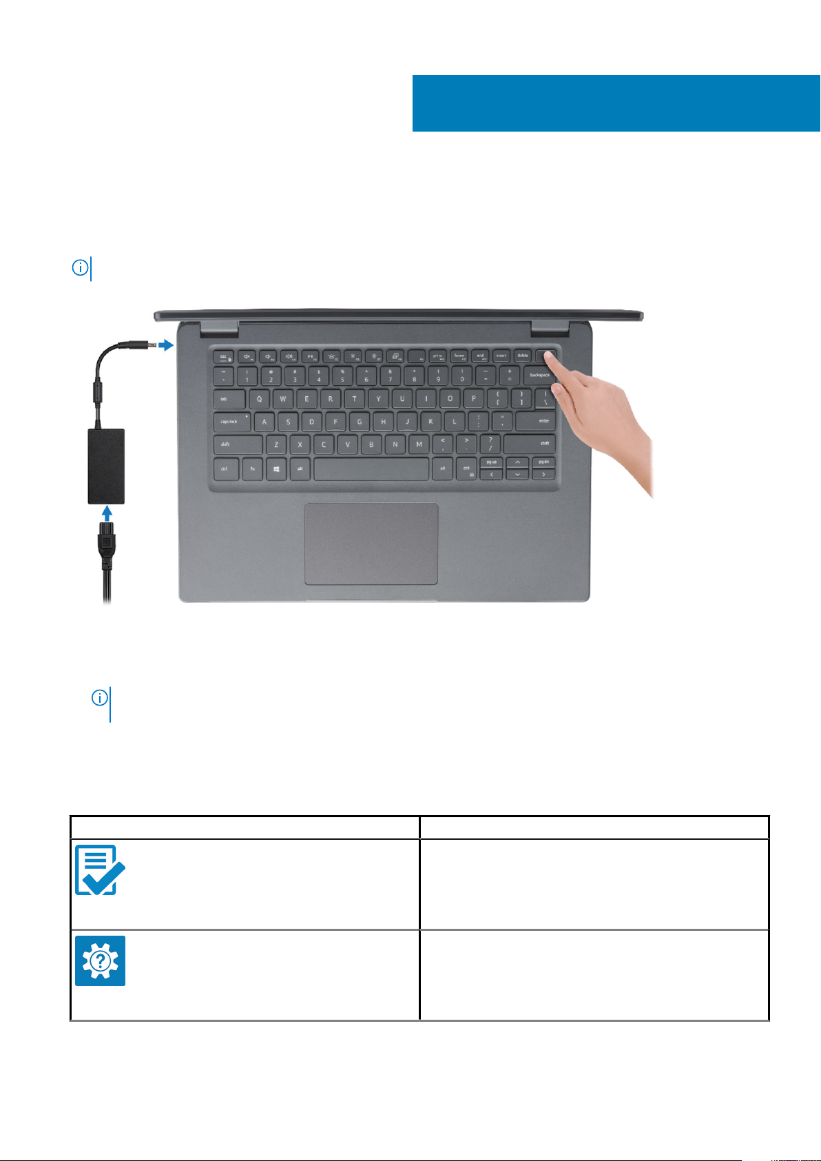
Steps
1. Connect the power adapter and press the power button.
NOTE: To conserve battery power, the battery might enter power saving mode.
1
Set up your computer
2. Finish Windows system setup.
Follow the on-screen instructions to complete the setup. When setting up, Dell recommends that you:
• Connect to a network for Windows updates.
NOTE:
If connecting to a secured wireless network, enter the password for the wireless network access when
prompted.
• If connected to the internet, sign-in with or create a Microsoft account. If not connected to the internet, create an offline account.
• On the Support and Protection screen, enter your contact details.
3. Locate and use Dell apps from the Windows Start menu—Recommended
Table 1. Locate Dell apps
Dell apps Details
Dell Product Registration
Register your computer with Dell.
Dell Help & Support
Access help and support for your computer.
6 Set up your computer
Page 7
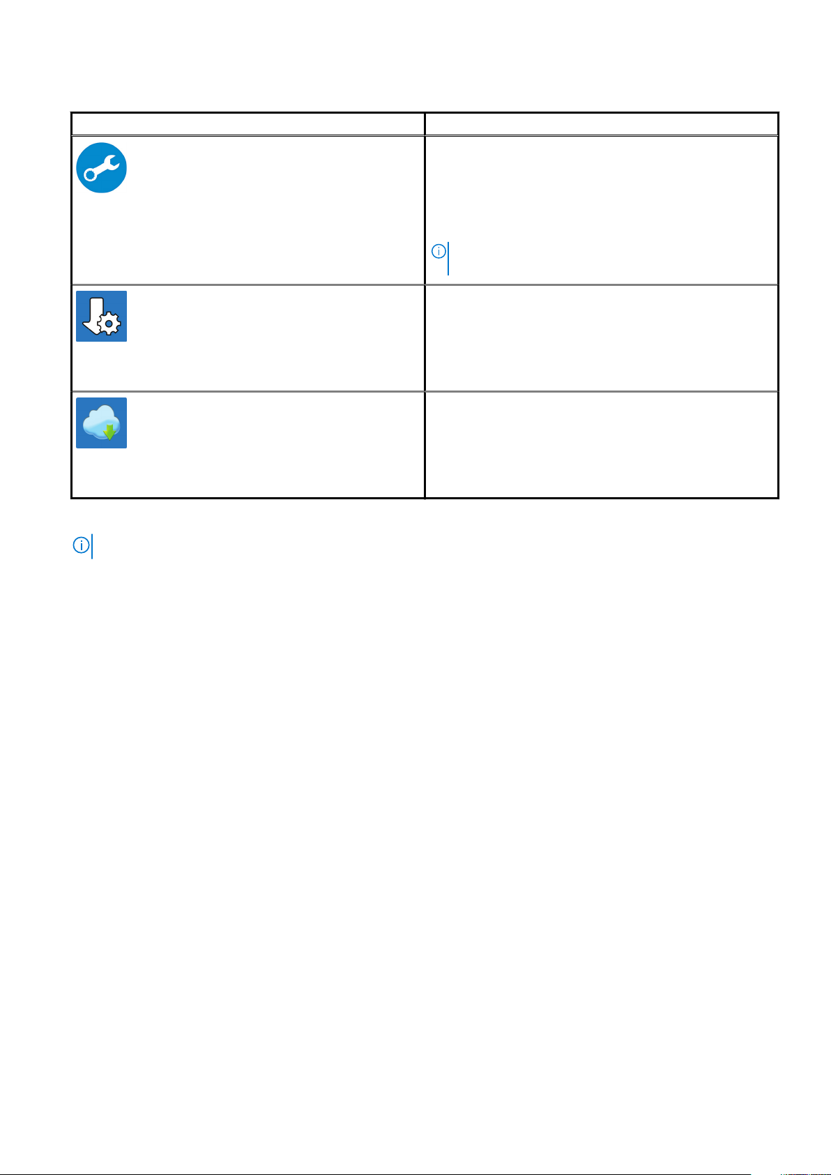
Table 1. Locate Dell apps(continued)
Dell apps Details
SupportAssist
Proactively checks the health of your computer’s hardware and
software.
Dell Update
Updates your computer with critical fixes and important device
drivers as they become available.
Dell Digital Delivery
Download software applications including software that is
purchased but not preinstalled on your computer.
NOTE: Renew or upgrade your warranty by clicking the
warranty expiry date in SupportAssist.
4. Create recovery drive for Windows.
NOTE: It is recommended to create a recovery drive to troubleshoot and fix problems that may occur with Windows.
For more information, see Create a USB recovery drive for Windows.
Set up your computer
7
Page 8

Create a USB recovery drive for Windows
Create a recovery drive to troubleshoot and fix problems that may occur with Windows. An empty USB flash drive with a minimum
capacity of 16 GB is required to create the recovery drive.
Prerequisites
NOTE: This process may take up to an hour to complete.
NOTE: The following steps may vary depending on the version of Windows installed. Refer to the Microsoft support site
for latest instructions.
Steps
1. Connect the USB flash drive to your computer.
2. In Windows search, type Recovery.
3. In the search results, click Create a recovery drive.
The User Account Control window is displayed.
4. Click Yes to continue.
The Recovery Drive window is displayed.
5. Select Back up system files to the recovery drive and click Next.
6. Select the USB flash drive and click Next.
A message appears, indicating that all data in the USB flash drive will be deleted.
7. Click Create.
8. Click Finish.
For more information about reinstalling Windows using the USB recovery drive, see the Troubleshooting section of your product's
Service Manual at www.dell.com/support/manuals.
2
8 Create a USB recovery drive for Windows
Page 9
Topics:
• Display view
• Left view
• Right view
• Palmrest view
• Bottom view
• Keyboard shortcuts
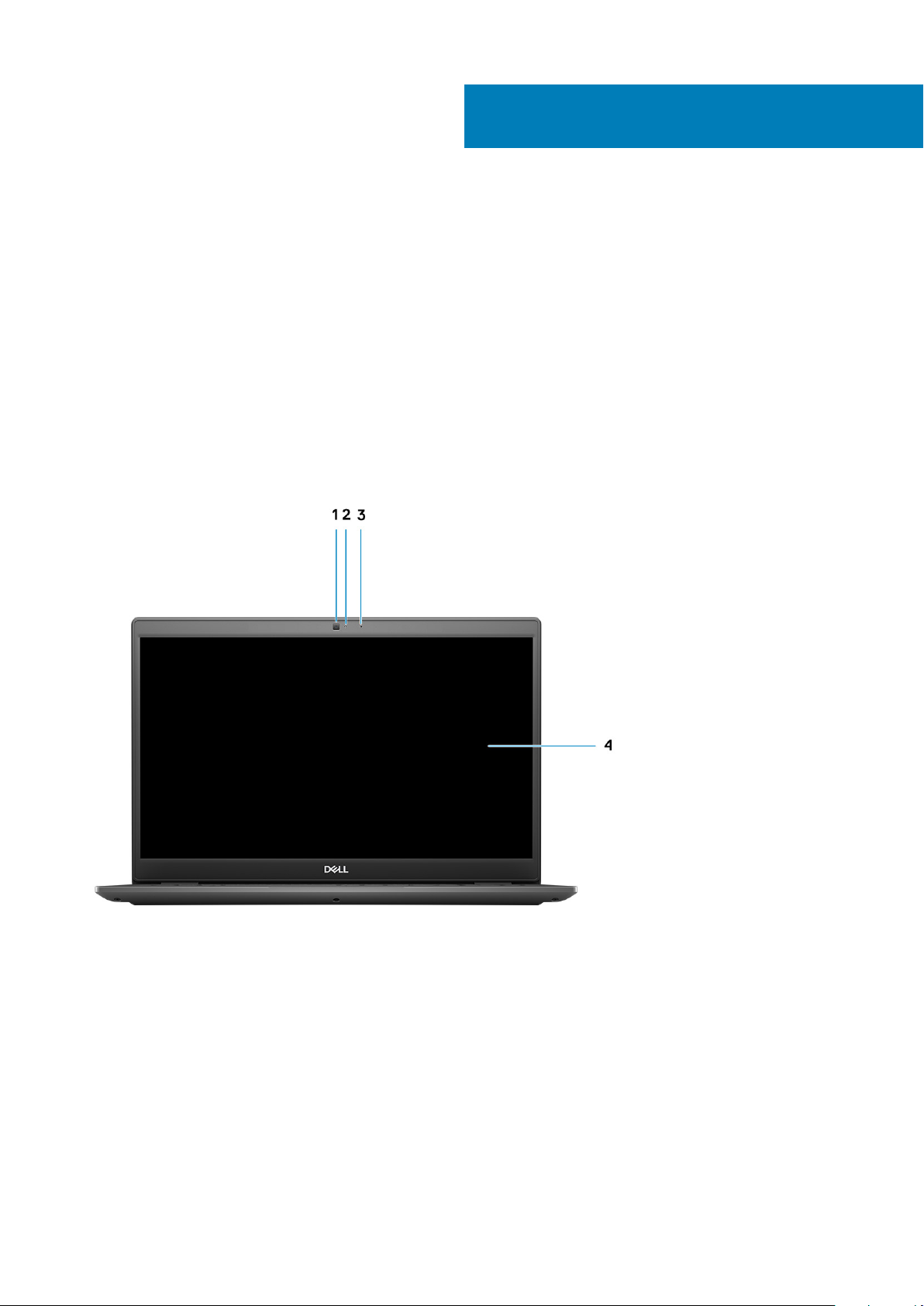
Display view
Latitude 3410 display
3
Chassis overview
1. Camera
2. Camera status light
3. Microphone
4. LCD Panel
Chassis overview 9
Page 10
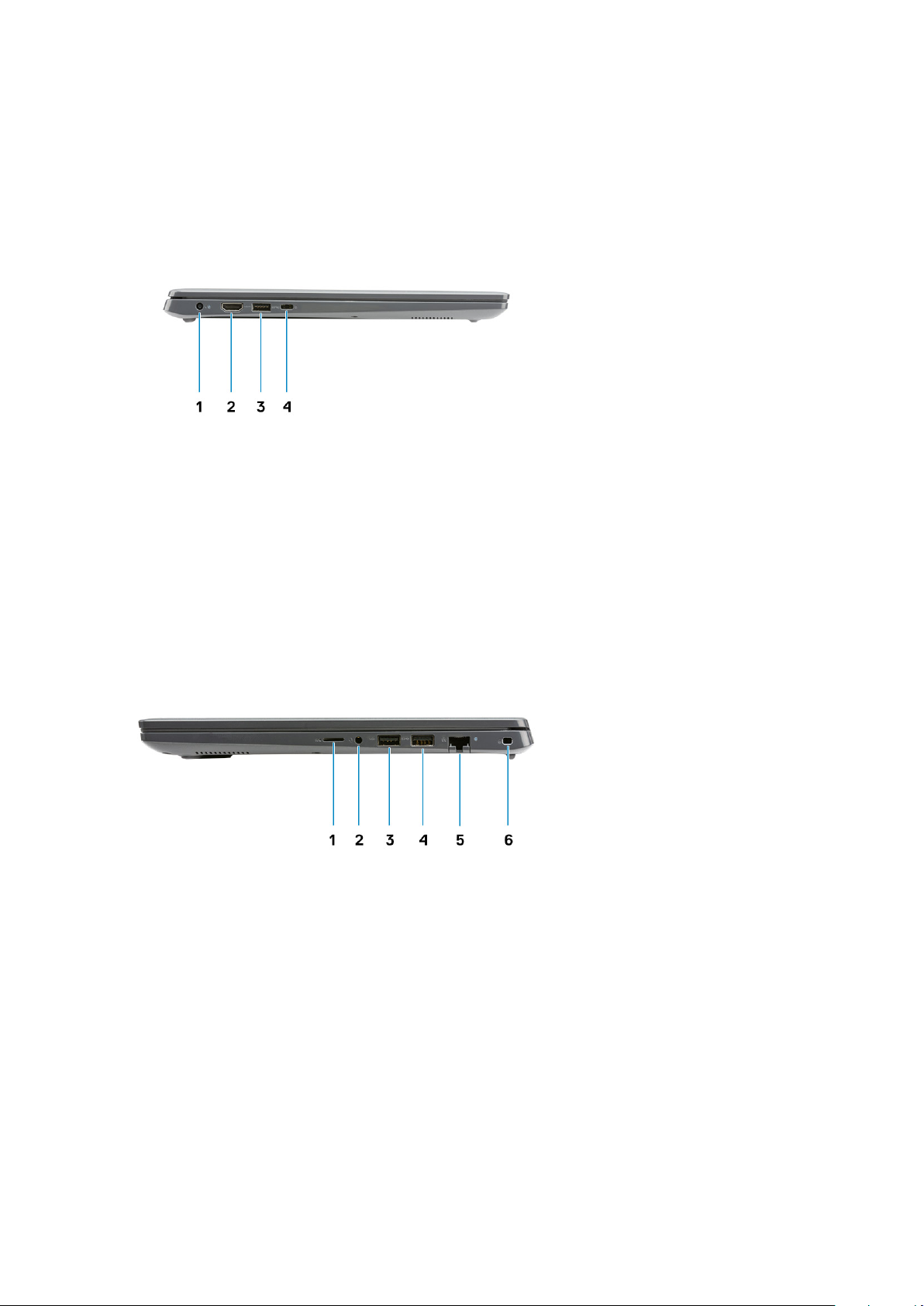
Left view
1. DC-in port 2. HDMI 1.4 port
3. USB 3.2 Gen 1 PowerShare 4. USB 3.2 Gen 1 Type-C port with DisplayPort 1.2 Alt mode
Right view
1. MicroSD 3.0 card reader slot
2. Universal audio jack
3. USB 2.0 Type-A port
4. USB 3.2 Gen 1 Type-A port
5. Network port
6. Wedge-shaped security slot
10
Chassis overview
Page 11
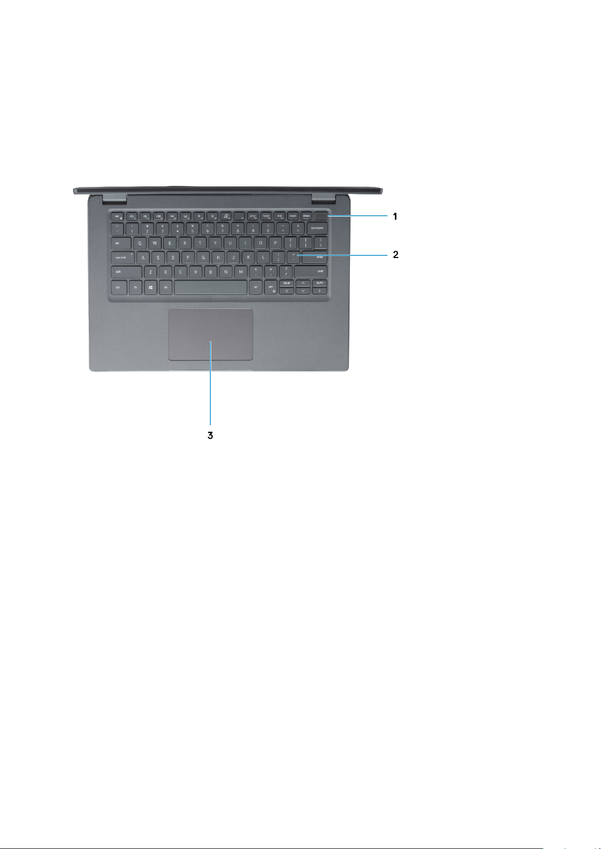
Palmrest view
1.
Power button with optional fingerprint reader
2. Keyboard
3. Touchpad
Chassis overview
11
Page 12
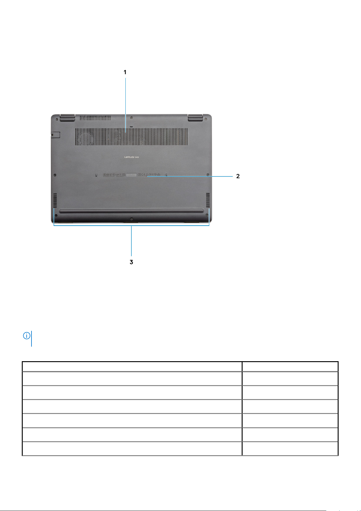
Bottom view
1.
Air vent
2. Service tag location
3. Speakers
Keyboard shortcuts
NOTE:
Keyboard characters may differ depending on the keyboard language configuration. Keys that are used for
shortcuts remain the same across all language configurations.
Table 2. List of keyboard shortcuts
Keys Primary behavior
Fn + Esc
Fn + F1
Fn + F2
Fn + F3
Fn + F4
Fn + F5
Toggle Fn-key lock
Mute audio
Decrease volume
Increase volume
Play/Pause
Turn on/off keyboard backlight
12 Chassis overview
Page 13

Table 2. List of keyboard shortcuts(continued)
Keys Primary behavior
Fn + F6
Fn + F7
Fn + F8
Fn + F10
Fn + F11
Fn + 12
Fn + Ctrl
Decrease brightness
Increase brightness
Switch to external display
Print screen
Home
End
Open application menu
Chassis overview 13
Page 14

Technical specifications
Processors
Table 3. Processors
Description Values
4
Processors
Wattage
Core count
Thread count
Speed
Cache
Integrated graphics
Intel Celeron 5205U
Processors
15 W 15 W 15 W 15 W 15 W
2 2 4 4 4
2 4 8 8 8
Up to 1.9 GHz Up to 4.1 GHz Up to 4.2 GHz Up to 4.4 GHz Up to 4.9 GHz
2 MB 4 MB 6 MB 6 MB 8 MB
Intel UHD Graphics Intel UHD Graphics Intel UHD Graphics Intel UHD Graphics Intel UHD Graphics
10th Generation
Intel Core i3
Processors,
i3-10110U
10th Generation
Intel Core i5
Processors,
i5-10210U
Chipset
Table 4. Chipset
Description Values
Processor
Intel 10th Generation Core i3 / i5 / i7 Intel Celeron 5000 Series
10th Generation
Intel Core i5
Processors,
i5-10310U
10th Generation Intel
Core i7 Processors,
i7-10510U
Chipset
DRAM bus width
PCIe bus
Intel Intel
64-bit 64-bit
Up to Gen 3 Up to Gen 2
Operating system
• Windows 10 Professional (64-bit)
• Ubuntu 18.04
• Neokylin 7.0 (PRTS)
14 Technical specifications
Page 15

Memory
Table 5. Memory specifications
Description Values
Slots
Type
Speed
Maximum memory
Minimum memory
Configurations supported
Two SODIMM slots
DDR4
• 2400 MHz (Intel Celeron)
• 2667 MHz (Intel Core i3 / i5 / i7)
32 GB
4 GB
• 4 GB DDR4 at 2400 MHz/2667 MHz (1x4 GB)
• 8 GB DDR4 at 2400 MHz/2667 MHz (2 x 4 GB)
• 8 GB DDR4 at 2400 MHz/2667 MHz (1 x 8 GB)
• 16 GB DDR4 at 2400 MHz/2667 MHz (1 x 16 GB)
• 16 GB DDR4 at 2400 MHz/2667 MHz (2 x 8 GB)
• 32 GB DDR4, 2400 MHz/2667 MHz (2 x 16 GB)
Storage
Your computer supports one of the following configurations:
• 2.5-in. 5400/7200 RPM, SATA hard drive
• M.2 2230/2280 for solid-state drive
The primary drive of your computer varies with the storage configuration. For computers:
• 2.5-in. 5400/7200 RPM, SATA hard drive
• M.2 2230/2280 for solid-state drive
NOTE: System's configured with 40Whr battery would only support M.2 solid-state drives for storage.
Table 6. Storage specifications
Form factor Interface type Capacity
2.5-in. 5400 rpm, hard drive SATA 1 TB
2.5-in. 7200 rpm, hard drive SATA 500 GB
M.2 2230/2280 solid-state drive PCIe NVMe 3x4 Upto 512 GB
M.2 2280 Intel Optane Memory (10th Gen Processors) PCIe NVMe 3x4 512 GB
NOTE: Intel Celeron 5000 Series Processors would support PCIe Gen 2 speeds only.
Intel UHD Graphics
Table 7. Intel UHD Graphics specifications
Intel UHD Graphics
Bus Type Integrated
Technical specifications 15
Page 16

Table 7. Intel UHD Graphics specifications(continued)
Intel UHD Graphics
Memory Type UMA
Graphics Level i3/i5/i7: GT2 (UHD)
Estimated Maximum Power Consumption (TDP) 15 W (included in the CPU power)
Overlay Planes Yes
Operating Systems Graphics/ Video API Support DirectX 12, OpenGL (4.5 from Intel CML POR)
Maximum Vertical Refresh Rate
Number of display supported
Multiple Display Support
External Connectors
• HDMI 1.4: 4096 x 2160 @ 60 Hz, 24bpp, Via optional USB
• Max Digital: (DP 1.2 over Type-C Port) 4096 x 2304 @ 60 Hz,
Up to three displays supported via DisplayPort Multi-Streaming
Technology (MST)
Via Type-C: HDMI 1.4 (via optional USB-C cable to HDMI cable);
DisplayPort 1.2 (via optional USB-C cable or USB-C to DP cable);
• USB Type–C port
• HDMI 1.4 port
Ports and connectors
Table 8. External ports and connectors
Description Values
External:
Network
USB
One Flip-down RJ 45 10/100/1000 Mbps
• One USB 3.2 Gen 1 Type-C port with DisplayPort alt mode/
• One USB 3.2 Gen 1 Type-A port with PowerShare
• One USB 3.2 Gen 1 Type-A port
• One USB 2.0 Type-A port
Type-C to HDMI dongle
24bpp
Power Delivery
Audio
Video
Power adapter port
Security
Card slot
One Universal Audio Jack
One HDMI 1.4 port
4.5 mm barrel-type
One Wedge shaped lock slot
One microSD 3.0 card slot
Table 9. Internal ports and connectors
Description Values
Internal:
One M.2 Key-M (2280 or 2230) for solid-state drive
One M.2 2230 Key-E for WLAN
16 Technical specifications
• One M.2 2230 slot for Wi-Fi
• One M.2 slot for 2230/2280 solid-state drive
Page 17

Table 9. Internal ports and connectors(continued)
Description Values
NOTE: To learn more about the features of different
types of M.2 cards, see the knowledge base article
SLN301626.
SIM card
Not Supported
Audio
Table 10. Audio specifications
Description Values
Controller
Stereo conversion
Internal interface
External interface
Speakers
Speaker Output Average
Speaker Output Peak
Realtek ALC3204
Supported
High definition audio
Universal Audio Jack
Two
2 W
2.5 W
Video
Table 11. Discrete graphics specifications
Discrete graphics
Controller External display support Memory size Memory type
NVIDIA GeForce MX230 Not Supported 2 GB GDDR5
Table 12. Integrated graphics specifications
Integrated graphics
Controller External display support Memory size Processor
Intel UHD Graphics • One HDMI 1.4
• One USB 3.2 Gen 1 Type-C with DisplatPort
1.2 alt mode
Shared system memory • Intel Celeron
Processor 5000
series processors
• Intel 10th
Generation Core
i3 / i5 / i7
processors
Technical specifications 17
Page 18

Camera
Table 13. Camera specifications
Standard Webcam
Description Values
Number of cameras
Type
Location
Sensor type
Resolution:
Still image
Video
Diagonal viewing angle
One
HD RGB camera
Front Camera
CMOS sensor technology
0.92 megapixel
1280 x 720 (HD) at 30 fps
87 degrees
Table 14. IR Webcam specifications
IR Webcam
Description
Number of cameras One
Type HD RGB-IR camera
Location Front Camera
Sensor type CMOS sensor technology
Resolution
Camera
Still image (megapixel) 0.92
Video 1280 x 720 (HD) at 30 fps
Infrared camera
Still image 0.23 megapixel
Video 640 x 360 at 30 fps
Diagonal viewing angle
Camera 87 degree
Infrared camera 87 degree
18 Technical specifications
Page 19

Communications
Ethernet
Table 15. Ethernet specifications
Description Values
Model number
Transfer rate
Integrated Realtek RTL8111H
e.g. 10/100/1000 Mbps
Wireless module
Table 16. Wireless module specifications
Description Values
Model number
Transfer rate
Frequency bands supported
Wireless standards
Encryption
Intel Wi-Fi 6 AX201 Qualcomm QCA61x4A
Up to 2400 Mbps Up to 867 Mbps
2.4 GHz/5 GHz 2.4 GHz/5 GHz
• WiFi 802.11a/b/g
• Wi-Fi 4 (Wi-Fi 802.11n)
• Wi-Fi 5 (Wi-Fi 802.11ac)
• Wi-Fi 6 (WiFi 802.11ax)
• 64-bit/128-bit WEP
• AES-CCMP
• TKIP
• WiFi 802.11a/b/g
• Wi-Fi 4 (Wi-Fi 802.11n)
• Wi-Fi 5 (Wi-Fi 802.11ac)
• 64-bit/128-bit WEP
• AES-CCMP
• TKIP
Bluetooth
Bluetooth 5.1 Bluetooth 5.0
Media-card reader
Table 17. Media-card reader specifications
Description Values
Type
Cards supported
One Micro SD 3.0 card
• Micro Secure Digital (mSD)
• Micro Secure Digital High Capacity(mSDHC)
• Micro Secure Digital Extended Capacity(mSDXC)
Power adapter
Table 18. Power adapter specifications
Description Values
Type
45 W 65 W 65 W Type-C (Optional)
Technical specifications 19
Page 20

Table 18. Power adapter specifications(continued)
Description Values
Connector dimensions:
Input voltage
Input frequency
Input current (maximum)
Output current (continuous)
Rated output voltage
Temperature range:
Operating
Storage
4.5 mm x 2.9 mm 4.5 mm x 2.9 mm 48.26 mm x 129.54 mm x
100 VAC x 240 VAC 100 VAC x 240 VAC 100 VAC x 240 VAC
50 Hz x 60 Hz 50 Hz x 60 Hz 50 Hz x 60 Hz
1.30 A 1.60 A / 1.70 A 1.70 A
2.31 A 3.34 A 3.25 A
19.50 VDC 19.50 VDC 20 VDC
0°C to 40°C (32°F to 104°F) 0°C to 40°C (32°F to 104°F) 0°C to 40°C (32°F to 104°F)
-40°C to 70°C (-40°F to
158°F)
-40°C to 70°C (-40°F to
158°F)
Battery
Table 19. Battery specifications
Description Values
215.9 mm
-40°C to 70°C (-40°F to
158°F)
Type
Voltage
Weight (maximum)
Dimensions:
Height
Width
Depth
Temperature range:
Operating
Storage
Operating time Varies depending on operating conditions
Charging time (approximate)
40 Whr 53 Whr
11.40 VDC 15.20 VDC
0.18 kg (0.40 lb) 0.24 kg (0.53 lb)
184.10 mm (7.25 in.) 239.10 mm (9.41 in.)
90.73 mm (3.57 in.) 90.73 mm (3.57 in.)
5.75 mm (0.23 in.) 5.75 mm (0.23 in.)
0°C to 35°C (32°F to 95°F) 0°C to 35°C (32°F to 95°F)
-40°C to 65°C (-40°F to 149°F) -40°C to 65°C (-40°F to 149°F)
and can significantly reduce under certain
power-intensive conditions.
4 hours (when the computer is off)
NOTE: Control the charging time,
duration, start and end time, and so
on using the Dell Power Manager
application. For more information on
the Dell Power Manager see,
My Dell
on www.dell.com/
Me and
Varies depending on operating conditions
and can significantly reduce under certain
power-intensive conditions.
4 hours (when the computer is off)
NOTE: Control the charging time,
duration, start and end time, and so
on using the Dell Power Manager
application. For more information on
the Dell Power Manager see,
My Dell
on www.dell.com/
Me and
20 Technical specifications
Page 21

Table 19. Battery specifications(continued)
Description Values
Life span (approximate) 300 discharge/charge cycles 300 discharge/charge cycles
Coin-cell battery
Operating time Varies depending on operating conditions
CR2032 CR2032
and can significantly reduce under certain
power-intensive conditions.
Dimensions and weight
Table 20. Dimensions and weight
Description Values
Height:
Front
Rear
Width
Depth
Weight
18.35 mm (0.72 in.)
18.35 mm (0.72 in.)
326.50 mm (12.85 in.)
226.38 mm (8.91 in.)
1.61 kg (3.54 lb)
NOTE: The weight of your tablet depends on the configuration
ordered and the manufacturing variability.
Varies depending on operating conditions
and can significantly reduce under certain
power-intensive conditions.
Display
Table 21. Display specifications
Decsription Values
Type
Panel technology
Luminance (typical)
Dimensions (active area):
Height
Width
Diagonal
Native resolution
Megapixels
Color gamut
Pixels per inch (PPI)
Full High Definition (FHD) Full High Definition (FHD) High Definition (HD)
WLED WVA(wide view angle) TN
220 nits 220 nits 220 nits
173.99 mm (6.85 in.) 173.99 mm (6.85 in.) 173.99 mm (6.85 in.)
309.35 mm (12.17 in.) 309.35 mm (12.17 in.) 309.35 mm (12.17 in.)
355.60 mm (14.00 in.) 355.60 mm (14.00 in.) 355.60 mm (14.00 in.)
1920 x 1080 1920 x 1080 1366 x 768
2.0736 2.0736 1.049
0.45 NTSC 45% Typ. NTSC 45% Typ.
157 157 112
Technical specifications 21
Page 22

Table 21. Display specifications (continued)
Decsription Values
Contrast ratio (min)
Response time (max)
Refresh rate
Horizontal view angle
Vertical view angle
Pixel pitch
Power consumption
(maximum)
Anti-glare vs glossy finish
Touch options
500:1 500:1 400:1
35 ms 35 ms 16 ms
60 Hz 60 Hz 60 Hz
80 degrees 80 degrees 40 degrees
80 degrees 80 degrees Top/bottom 10/30 degrees
0.16 mm 0.16 mm 0.22 mm
3.15 W 3.15 W 3.15 W
Anti-glare Anti-glare Anti-glare
Yes No No
Fingerprint reader
Table 22. Fingerprint reader specifications
Description Values
Sensor technology
Sensor resolution
Sensor area
Sensor pixel size
Capacitive
500 dpi
4.06 mm x 3.25 mm
80 x 64
Security
Table 23. Security specifications
Features Specifications
Trusted Platform Module (TPM) 2.0 Integrated on system board
Fingerprint reader Optional
Wedge-shaped lock slot Standard
NOTE: Systems with Intel Celeron 5000 series processors ship with firmware TPM only.
Security Software
Table 24. Security Software specifications
Specifications
Dell Client Command Suite
Optional Dell Data Security and Management Software
22 Technical specifications
Page 23

Table 24. Security Software specifications(continued)
Specifications
Dell Client Command Suite
Dell BIOS Verification
Optional Dell Endpoint Security and Management Software
VMware Carbon Black Endpoint Standard
VMware Carbon Black Endpoint Standard + Secureworks Threat Detection and Response
Dell Encryption Enterprise
Dell Encryption Personal
Carbonite
VMware Workspace ONE
Absolute® Endpoint Visibility and Control
Netskope
Dell Supply Chain Defense
Computer environment
Airborne contaminant level: G1 as defined by ISA-S71.04-1985
Table 25. Computer environment
Description Operating Storage
Temperature range
Relative humidity (maximum)
Vibration (maximum)
Shock (maximum)
Altitude (maximum)
* Measured using a random vibration spectrum that simulates user environment.
† Measured using a 2 ms half-sine pulse when the hard drive is in use.
*
0°C to 35°C (32°F to 95°F) -40°C to 65°C (-40°F to 149°F)
10% to 90% (non-condensing) 0% to 95% (non-condensing)
0.66 GRMS 1.30 GRMS
110 G† 160 G†
-15.2 m to 3048 m (4.64 ft to 5518.4 ft) -15.2 m to 10668 m (4.64 ft to 19234.4 ft)
Technical specifications
23
Page 24

This chapter details the supported operating systems along with instructions on how to install the drivers.
Topics:
• Downloading Windows drivers
Downloading Windows drivers
Steps
1. Turn on the notebook.
2. Go to Dell.com/support.
3. Click Product Support, enter the Service Tag of your notebook, and then click Submit.
NOTE: If you do not have the Service Tag, use the auto detect feature or manually browse for your notebook model.
4. Click Drivers and Downloads.
5. Select the operating system installed on your notebook.
6. Scroll down the page and select the driver to install.
7. Click Download File to download the driver for your notebook.
8. After the download is complete, navigate to the folder where you saved the driver file.
9. Double-click the driver file icon and follow the instructions on the screen.
5
Software
24 Software
Page 25

6
System setup
CAUTION: Unless you are an expert computer user, do not change the settings in the BIOS Setup program. Certain
changes can make your computer work incorrectly.
NOTE: Before you change BIOS Setup program, it is recommended that you write down the BIOS Setup program screen
information for future reference.
Use the BIOS Setup program for the following purposes:
• Get information about the hardware installed in your computer, such as the amount of RAM and the size of the hard drive.
• Change the system configuration information.
• Set or change a user-selectable option, such as the user password, type of hard drive installed, and enabling or disabling base devices.
Topics:
• Boot menu
• Navigation keys
• Overview
• Boot Configuration
• Integrated Devices
• Storage
• Connection
• Power
• Security
• Passwords
• Update Recovery
• System Management
• Keyboard
• Pre-boot Behavior
• Virtualization
• Performance
• System Logs
• Updating the BIOS in Windows
• System and setup password
Boot menu
Press <F12> when the Dell logo appears to initiate a one-time boot menu with a list of the valid boot devices for the system. Diagnostics
and BIOS Setup options are also included in this menu. The devices that are listed on the boot menu depend on the bootable devices in
the system. This menu is useful when you are attempting to boot to a particular device or to bring up the diagnostics for the system. Using
the boot menu does not make any changes to the boot order stored in the BIOS.
Table 26. UEFI Boot options
Options
Windows Boot Manager
UEFI hard drive
System setup 25
Page 26

Table 27. Other Options
Options Description
BIOS SETUP Allows the user to configure the BIOS and control system
functions
Diagnostics Allows the user to run system tests to identify issues
BIOS Update Allows the user to search and install the latest BIOS updates
SupportAssist OS Recovery Used to analyze, repair, and restore the operating system on the
system
BIOS Flash Update - Remote
Device Configuration
Navigation keys
NOTE: For most of the System Setup options, changes that you make are recorded but do not take effect until you
restart the system.
Keys Navigation
Up arrow Moves to the previous field.
Down arrow Moves to the next field.
Enter Selects a value in the selected field (if applicable) or follow the link in the field.
Spacebar Expands or collapses a drop-down list, if applicable.
Tab Moves to the next focus area.
Esc Moves to the previous page until you view the main screen. Pressing Esc in the main screen displays a message
that prompts you to save any unsaved changes and restarts the system.
Overview
This section provides hardware specification for the system and contains no modifiable settings.
Table 28. BIOS Overview Page
Options Description
Series and system model number
Battery
This field shows the following information:
• BIOS Version - The version of the BIOS installed on the
computer.
• Service tag - The unique 7 digit hexadecimal identification
number for the computer.
• Asset tag
• Manufacture Date - The date for when the unit was
manufactured.
• Ownership Date - The date for when the unit's ownership was
transferred to the end user.
• Express Service Code - An alternative to Service Tag, 11-digit
numerical identification number for the computer.
• Ownership Tag
• Signed Firmware Update - This helps to verify that only Dell
Signed and released BIOS can be installed on the computer.
The Battery field provides battery and adapter related information:
26 System setup
Page 27

Table 28. BIOS Overview Page(continued)
Options Description
• Primary battery - This helps identify if the system is running on
the primary battery.
• Battery level - This gives the percentage of battery backup
remaining for the computer.
• Battery state - This helps identify if the battery is in charging or
active use state.
• Health - This helps identify the health of the battery. It would
show one of the following states based on the battery life
remaining:
○ Excellent
○ Good
○ Fair
○ Poor
• AC Adapter - This helps identify if the charger is plugged in and
mentions the wattage of the charger connected.
Processor
Memory
The Processor field provides information related to the CPU on the
computer:
• Processor Type - This field mentions the CPU model and
generation information.
• Maximum Clock Speed - This field mentions the maximum
clock speed that the CPU is capable of reaching.
• Minimum Clock Speed - This field mentions the minimum clock
speed that the CPU is capable of reaching.
• Current Clock Speed - This field mentions the clock speed that
the CPU is running at currently.
• Core Count - This field gives the count of the physical cores on
the CPU.
• Processor ID
• Processor L3 Cache - This field gives mentions the amount of
cache storage available on the CPU.
• Microcode Version
• Intel Hyper-Threading Capable - This field helps identify if the
CPU is capable of Hyper-Threading.
• 64-bit Technology - This field helps identify the CPU
architecture.
The Memory field provides information related to the memory on
the computer:
• Memory Installed - This field gives the amount of memory
installed available on the computer.
• Memory Available - This field gives the amount of memory
available for use on the computer.
• Memory Speed - This field mentions the speed at which the
memory runs on the computer.
• Memory Channel Mode - This field helps us identify if the
computer has Dual-Channel memory utilization capability.
• DIMM_SLOT 1 - This field shows the capacity of the memory
installed in the first DIMM slot.
• DIMM_SLOT 2 - This field shows the capacity of the memory
installed in the second DIMM slot.
Devices
The Devices field provides information related to the memory on
the computer:
System setup 27
Page 28

Table 28. BIOS Overview Page(continued)
Options Description
• Panel Type - This field mentions the type of display panel used
on the computer.
• Video controller - This field mentions the type of video
controller used on the computer.
• Video Memory - This field gives the capacity of the video
memory available for use on the computer.
• Wi-Fi Device - This field mentions the type wireless device
available for use on the computer.
• Native Resolution - This field mentions the native video
resolution supported on the computer.
• Video BIOS Version - The version of the BIOS installed on the
computer.
• Audio Controller - This field mentions the type of audio
controller used on the computer.
• Bluetooth Device - This field mentions the type Bluetooth
device available for use on the computer.
• LOM MAC Address - This field provides the unique MAC
address for the computer.
• Pass Through MAC Address - This field provides the MAC
address used to override the dock or dongle MAC address
every time it's connected to the network.
Boot Configuration
This section provides Boot Configuration related details and settings.
Table 29. Boot Configuration:
Options Description
Boot Sequence
Boot Mode: UEFI only
Secure Digital(SD) Card Boot
Secure Boot
Enable Secure Boot
Secure Boot Mode
This section allows the user to choose the first bootable device
that the computer should use to boot the system. It lists all
potential bootable devices.
• Windows Boot Manager
• UEFI Boot Drive
• Add Boot option - Allows the user to manually add a Boot path.
This section contains a toggle switch that allows the user to enable
or disable the option to allow the computer to boot from an SD
Card.
This section contains a toggle switch that allows the user to enable
or disable Secure Boot.
This section allows the user to select one of the two Secure Boot
options available on the computer:
• Deployed Mode - This mode checks the integrity of UEFI
drivers and bootloaders before allowing execution. This option
allows for full Secure Boot protections.
• Audit Mode - This mode performs a signature check but never
does a block execution of all UEFI drivers and bootloaders. This
mode is only used when making changes to Secure Boot Keys.
28 System setup
Page 29

Table 29. Boot Configuration: (continued)
Options Description
Expert Key Management
Enable Custom Mode
Custom Mode Key Management
This section contains a toggle switch that allows the user to enable
or disable Custom Mode. This mode allows the PK, KEK, db and
dbx security key databases to be manipulated.
This section helps the user to select the Key Database to allow
modification. The options available are as below:
• PK
• KEK
• db
• dbx
Integrated Devices
This section provides Integrated Devices details and settings.
Table 30. Integrated Devices
Options Description
Date/Time
Date
Time
This section allows the user to change the date which takes effect
immediately. The format used is MM/DD/YYYY
This section allows the user to change the time which takes effect
immediately. The format used is HH/MM/SS in 24 hour format.
The user also has an option to switch between 12-hours or 24hours clock.
Camera
Enable Camera
Audio
Enable Audio
USB Configuration
Storage
This section provides Storage details and settings.
This section contains a toggle switch that allows the internal
webcam.
This section contains a toggle switch that allows the user to enable
or disable the audio on the computer. It also allows the user to:
• Enable Microphone
• Enable Internal Speakers
This section helps the user to make changes to the USB settings
on the computer. The options available are as follows:
• Enable USB Boot Support - Allows the system to boot from an
external USB device.
• Enable External USB Ports - Allows the user to enable or
disable the USB ports on the computer.
System setup
29
Page 30

Table 31. Storage
Options Description
SATA Operation
SATA Operation
Storage Interface
Port Enablement
SMART Reporting
Enable SMART Reporting
Drive Information
This section allows the user to select the operating mode of the
integrated SATA hard drive controller. The following options are
available here:
• Disabled - SATA controllers are disabled.
• AHCI - SATA is configured in AHCI mode.
• RAID On - SATA is setup to support RAID (Intel Rapid Storage
Technology).
This section allows the user to enable or disable the onboard drives
on the computer. The following options are available here:
• SATA-0
• M.2 PCIe SSD-0
This section contains a toggle switch that allows the user to enable
or disable the S.M.A.R.T(Self-Monitoring, Analysis, and Reporting
Technology) option on the system.
This section provides information about the connected and active
drives on the computer.The following options are available here:
• SATA-0
○ Type
○ Device
• M.2 PCIe SSD-0
○ Type
○ Device
Enable MediaCard
This section allows the user to switch all media cards On/Off, or
enable/disable the media card in read-state only. The options seen
are as below
• Secure Digital(SD) Card
• Secure Digital(SD) Card Read-Only Mode
Connection
This section provides connection details and settings.
Table 32. Connection
Options Description
Wireless Device Enable
Enable UEFI Network Stack
This section contains a toggle switch that allows the user to enable
or disable WLAN and Bluetooth on the computer. The options are
as follows:
• WLAN
• Bluetooth
This section contains a toggle switch that allows the user to enable
or disable installation of UEFI networking protocols.
30 System setup
Page 31

Table 32. Connection(continued)
Options Description
Wireless Radio Control
This section contains a toggle switch that allows the user to enable
or disable a feature where the system will sense a connection to a
wired network and disable the WLAN or WWAN connection.
Power
This section provides power details and settings.
Table 33. Power
Options Description
Battery configuration
This section provides options to enable different power modes on
the computer. The options are as follows:
• Adaptive - battery settings are adaptively optimized based on
the users typical battery usage patterns.
• Standard - Fully charge the battery at a standard rate.
• ExpressCharge - The battery may be charged over a shorter
period using Dell's fast charging technology.
• Primarily AC use - The battery lifespan for users who primarily
operate their system while plugged in to an external power
source.
• Custom - Custom select when the battery starts and stops
charging.
○ Custom Charge Start
○ Custom Charge Stop
Advanced Configuration
Enable Advanced Battery Charge Configuration
Peak Shift
USB PowerShare
Thermal Management
This feature maximizes battery health while still supporting heavy
use during the work day. The section contains a toggle switch that
allows the user to enable or disable this feature and set the daily
times and work time periods.
This feature allows the computer to run on battery during peak
usage hours. The section contains a toggle switch that allows the
user to enable or disable this feature and set the Peak Shift
Start/End times and Peak Shift Charge Start/End.
This setting contains a toggle witch which allows the user to
enable or disable this feature. It allows for any external USB
devices to charge via the designated USB PowerShare port, even
when the computer is on sleep mode.
This setting allows for cooling fan and processor heat management
to adjust system performance, noise and temperature. The options
available are as below:
• Optimized - Standard setting for cooling fan and processor
heat management.
• Cool - Processor and cooling fan speed are adjusted for a
cooler system surface temperature.
• Quiet - Processor and cooling fan speed are adjusted to reduce
fan noise.
• Ultra Performance - Processor and cooling fan speed are
increased for more performance.
System setup 31
Page 32

Security
This section provides security details and settings.
Table 34. Security
Options Description
TPM 2.0 Security
TPM 2.0 Security On
PPI Bypass for Enabled Commands
PPI Bypass for Disabled Commands
PPI Bypass for Clear Commands
Attestation Enable
Key Storage Enable
SHA-256
This section contains a toggle switch to select whether Trusted
Platform Module(TPM) is visible to the Operating System(OS).
This section contains a toggle switch which controls the TPM
Physical Presence Interface(PPI). When enabled, this setting
allows the OS to skip BIOS PPI user prompts when issuing TPM
PPI enable and activate commands.
This section contains a toggle switch which controls the TPM
Physical Presence Interface(PPI). When enabled, this setting will
allow the OS to skip BIOS PPI user prompts when issuing TPM PPI
disable and deactivate commands(#2, 4, 7, 9, & 11).
This section contains a toggle switch which controls the TPM
Physical Presence Interface(PPI). When enabled, this setting will
allow the OS to skip BIOS PPI user prompts when issuing the clear
command.
This section contains toggle switch which lets the user control
whether the TPM Endorsement Hierarchy is available to the OS.
This sections contains a toggle switch that allows the user to
control whether TPM Storage Hierarchy is available to the
operating system.
This sections contains a toggle switch that when enabled, allows
the BIOS and the TPM to use the SHA-256 hash algorithm to
extend measurements into the TPM PCRs during BIOS boot.
Clear
TPM State
Intel Software Guard Extension
Intel SGX
SMM Security Mitigation
Data Wipe on Next Boot
This section contains toggle switch which clears the TPM owner
information, and returns the TPM to the default state.
This section allows the user to enable or disable the TPM. this is
the normal operating state for the TPM when you want to use its
complete arrays of capabilities.
This sections allows the user to select the Intel Software Guard
Extension Enclave Reserve Memory Size. The options are as
follows:
• Disabled
• Enabled
• Software Control
This section allows the user to enable or disable UEFI SMM
security Mitigation protections.
32 System setup
Page 33

Table 34. Security(continued)
Options Description
Start Data Wipe
Absolute
Absolute
UEFI Boot Path Security
UEFI Boot Path Security
This section contains toggle switch which when enabled ensures
that the BIOS will queue up a data wipe cycle for storage device(s)
connected to the motherboard on the next reboot.
This section lets the user enable, disable or permanently disable the
BIOS module interface of the optional Absolute Persistence
Module service from Absolute Software. The options available are
as follows:
• Enable Absolute - Enables Absolute Persistence and load the
firmware Persistence Module
• Disable Absolute - Disables Absolute Persistence. The firmware
Persistence Module is not installed.
• Permanently Disable Absolute - Permanently disables Absolute
Persistence module interface from further use.
This section lets the user control whether or not the system will
prompt the user to enter the admin password(if set) when booting
to a UEFI booth path device from F12 boot menu. The options
available are as below:
• Never
• Always
• Always Except Internal HDD
• Always Except Internal HDD&PXE
Passwords
This section provides details on password settings.
Table 35. Passwords
Options Description
Admin Password
System Password
Internal HDD-0 Password
Password Configurator
Upper Case Letter
Lower Case Letter
Digit
Special Character
Minimum Character
This field allows the user to set, change, or delete the administrator
password.
This field allows the user to set, change, or delete the system
password.
This field allows the user to set, change, or delete the Hard Drive
password.
Enable or disable reinforced use of upper case letters.
Enable or disable reinforced use of lower case letters.
Enable or disable reinforced use of at least one digit.
Enable or disable reinforced use of at least one special character.
Allows the user to select the number of characters allowed for a
password.
System setup 33
Page 34

Table 35. Passwords(continued)
Options Description
Password Bypass
Password Bypass
Password Changes
Enable Non-Admin Password Changes
Password Changes
Enable Non-Admin Password Changes
Admin Setup Lockout
Enable Admin Setup Lockout
Master Password Lockout
Enable Master Password Lockout
When enabled, this always prompts for system and internal hard
drive passwords when powered on from Off state. Options
available are as below:
• Disabled
• Reboot Bypass
This section contains a toggle switch which when on, user can
change system and hard drive password without the need for
admin password.
This section contains a toggle switch which when on, user can
change system and hard drive password without the need for
admin password.
This section contains a toggle switch which allows the
administrator to control how users can or cannot access BIOS
setup.
This section contains a toggle switch which allows the user to
disable master password support.
Update Recovery
This section provides details on Update Recovery settings.
Table 36. Update Recovery
Options Description
UEFI capsule Firmware Updates
Enable UEFI Capsule Firmware Updates
BIOS Recovery from Hard Drive
BIOS Recovery from Hard Drive
BIOS Downgrade
Allow BIOS Downgrade
SupportAssist OS Recovery
SupportAssist OS Recovery
This field contains a toggle switch which allows the user to enable
or disable BIOS updates via UEFI capsule update packages.
This field contains a toggle switch which allows the user to enable
or disable recovery from certain corrupted BIOS conditions from a
recovery file on the user's primary hard drive or an external USB
key.
This field contains a toggle switch which allows the user to enable
or disable flashing of the system firmware to previous revisions.
This field contains a toggle switch which allows the user to enable
or disable the boot flow for SupportAssist OS Recovery tool in the
events of certain system errors.
34 System setup
Page 35

Table 36. Update Recovery(continued)
Options Description
BIOSConnect
BIOSConnect
Dell Auto OS Recovery Threshold
Dell Auto OS Recovery Threshold
This field contains a toggle switch which allows the user to enable
or disable BIOSConnect setup to attempt cloud Service OS
recovery if the main operating system fails to boot with a set
number of failures.
This field allows the user to select and number of failed boot
attempts by the system before SupportAssist OS Recovery is
triggered. The options here are as below:
• Off
• 1
• 2
• 3
System Management
This section provides System Management settings.
Table 37. System Management
Options Description
Service Tag
Service Tag
This field provides the unique Service Tag of the computer.
Asset Tag
Asset Tag
AC Behaviour
Wake on AC
Wake on LAN
Wake on LAN
Auto On Time
Auto On Time
This field provides the unique up to 64 character identification that
can be set by the IT administrator.
This field contains a toggle switch which allows the user to enable
or disable the feature where the system boots when charger is
detected.
This field allows the user to select if and how the system should
boot when connected to LAN. The options here are as follows:
• Disabled - The system will not boot with any special LAN
signals.
• LAN only - Allows the system to be powered on by a special
LAN signal from a network computer.
• LAN with PXE Boot - Allows the system to wake-up from S4
or S5 state and boot to PXE.
This field allows the user to set defined days/time when the sytem
can automatically power on. The options here are as follows:
• Disabled
• Everyday
• Weekdays
System setup 35
Page 36

Table 37. System Management(continued)
Options Description
• Select Days
Keyboard
This section provides keyboard settings.
Table 38. Keyboard
Options Description
Numlock Enable
Enable Numlock
Fn Lock Options
Fn Lock Options
Keyboard Illumination
Keyboard Illumination
Keyboard Backlight Timeout on AC
Keyboard Backlight Timeout on AC
This field contains a toggle switch to enable or disable Numlock
function on boot.
This field contains a toggle switch to change the mode of the
function keys. The options are as follows:
• Lock Mode Standard - Traditional F1-F12 functions
• Lock Mode Secondary - Enables secondary functions on the Fn
keys.
This field allows the user to set the keyboard illumination settings.
The options available are as follows:
• Disabled - The keyboard illumination will be off
• Dim - Enable the keyboard illumination feature at 50%
brightness level
• Bright - Enable the keyboard illumination feature at 100%
brightness level
This field allows the user to define the timeout value for the
backlight when the AC adapter is connected to the computer. The
options here are as follows:
• 5 seconds
• 10 seconds
• 15 seconds
• 30 seconds
• 1 minute
• 5 minute
• 15 minute
• Never
Keyboard Backlight Timeout on Battery
Keyboard Backlight Timeout on Battery
36 System setup
This field allows the user to define the timeout value for the
backlight when the battery is powering to the computer. The
options here are as follows:
• 5 seconds
• 10 seconds
• 15 seconds
• 30 seconds
Page 37

Table 38. Keyboard(continued)
Options Description
• 1 minute
• 5 minute
• 15 minute
• Never
Pre-boot Behavior
This section provides Pre-boot Behavior details and settings.
Table 39. Pre-boot Behavior
Options Description
Adapter Warnings
Enable Adapter Warnings
Warning and Errors
Warning and Errors
USB-C Warnings
Enable Dock Warning Messages
Fastboot
Fastboot
This field contains a toggle switch to enable or disable warning
messages during boot when adapters with low power capacity are
detected.
This field allows the user to enable or disable boot process to be
paused only when warnings or errors are detected. The options are
as follows:
• Prompt on Warnings and Errors - Stop, prompt and wait for
user input when warnings or errors are detected
• Continue on Warnings - Continue when warnings are detected
but pause on errors
• Continue on Warnings and Errors - Continue when either
warnings or errors are detected during POST
This field contains a toggle switch to enable or disable dock
warning messages.
This field allows the user to configure the speed of the UEFI boot
process. The options here are as follows:
• Minimal - reduces boot time by skipping certain hardware and
configuration initialization during boot
• Thorough - Performs complete hardware and configuration
initialization during boot
• Auto - Allows the BIOS to decide configuration initialization
performed during boot
Extend BIOS POST Time
Extend BIOS POST Time
MAC Address Pass-Through
This field allows the user to configure the BIOS POST load time.
The options are as follows:
• 0 seconds
• 5 seconds
• 10 seconds
System setup 37
Page 38

Table 39. Pre-boot Behavior(continued)
Options Description
MAC Address Pass-Through
This field allows the user to configure the MAC address passthrough replacing the external NIC MAC address.:
• System Unique MAC Address
• Integrated NIC 1 MAC Address
• Disabled
Virtualization
This section provides details on Virtualization settings.
Table 40. Virtualization
Options Description
Intel Virtualization Technology
Enable Intel Virtualization Technology(VT)
VT for Direct I/O
Enable Intel VT for Direct I/O
Intel Trusted Execution Technology(TXT)
This field contains a toggle switch to enable or disable
Virtualization to run Virtual machine monitor(VMM).
This field allows the user to enable or disable the system from
being able to perform VT for Direct I/O.
Enable Intel Trusted Execution Technology(TXT)
Performance
This section provides Performance settings.
Table 41. Performance
Multi-Core Support
Active Cores
This field contains a toggle switch to enable or disable the option
to allow a Measured VMM to utilize the additional hardware
capabilities provided by Intel TXT. The following must be enabled
to configure Intel TXT:
• Trusted Platform Module(TPM)
• Intel Hyper-Threading
• All CPU cores(Multi-Core Support)
• Intel Virtualization technology
• Intel VT for Direct I/O
This field allows the user to configure the number of active cores
on the computer. The options are as follows:
• All Cores
• 1
• 2
• 3
Intel SpeedStep
Enable Intel SpeedStep Technology
38 System setup
This field contains a toggle switch to enable or disable Intel
SpeedStep Technology which allows the computer to dynamically
Page 39

Table 41. Performance(continued)
C-States Control
adjust processor voltage and core frequency, decreasing average
power consumption and heat production.
Enable C-States Control
Intel Turbo Boost Technology
Enable Intel Turbo Boost Technology
Intel Hyper-Threading Technology
Enable Intel Hyper-Threading Technology
System Logs
This section contains BIOS, Thermal and Power event logs.
Table 42. System Logs
This field contains a toggle switch to enable or disable C-States
Control that configures the CPU's ability to enter and exit low
power states. When off, it disables all C-States.
This field allows the user to enable or disable Intel Turbo Boost
Technology.
• Disabled - Does not allow the Intel Turbo Boost Technology
driver to increase the performance state of the processor
above the standard performance.
• Enabled - Allows the Intel Turbo Boost Technology to increase
the performance of the CPU or graphics processor.
This field allows the user to configure this feature where the
processor resources are used more effectively, enabling multiple
threads to run on each core.
Options Description
BIOS Event Log
Clear BIOS Event log
Thermal Event Log
Clear Thermal Event Log
Power Event Log
Clear Power Event Log
This field contains a toggle switch to Keep or Clear BIOS Event
logs. It also lists all saved events(Date, Time, Message).
This field contains a toggle switch to Keep or Clear Thermal Event
logs. It also lists all saved events(Date, Time, Message).
This field contains a toggle switch to Keep or Clear Power Event
logs. It also lists all saved events(Date, Time, Message).
Updating the BIOS in Windows
Prerequisites
It is recommended to update your BIOS (System Setup), when you replace the system board or if an update is available. For laptops,
ensure that your computer battery is fully charged and connected to a power before initiating a BIOS update.
About this task
If BitLocker is enabled, it must be suspended prior to updating the system BIOS, and then re enabled after the
NOTE:
BIOS update is completed.
System setup 39
Page 40

Steps
1. Restart the computer.
2. Go to Dell.com/support.
• Enter the Service Tag or Express Service Code and click Submit.
• Click Detect Product and follow the instructions on screen.
3. If you are unable to detect or find the Service Tag, click Choose from all products.
4. Choose the Products category from the list.
NOTE: Choose the appropriate category to reach the product page
5. Select your computer model and the Product Support page of your computer appears.
6. Click Get drivers and click Drivers and Downloads.
The Drivers and Downloads section opens.
7. Click Find it myself.
8. Click BIOS to view the BIOS versions.
9. Identify the latest BIOS file and click Download.
10. Select your preferred download method in the Please select your download method below window, click Download File.
The File Download window appears.
11. Click Save to save the file on your computer.
12. Click Run to install the updated BIOS settings on your computer.
Follow the instructions on the screen.
Updating BIOS on systems with BitLocker enabled
CAUTION:
recognize the BitLocker key. You will then be prompted to enter the recovery key to progress and the system will ask for
this on each reboot. If the recovery key is not known, this can result in data loss or an unnecessary operating system
reinstall. For more information about this subject, see Knowledge Article: Updating the BIOS on Dell Systems With
BitLocker Enabled
If BitLocker is not suspended before updating the BIOS, the next time you reboot the system it will not
Updating your system BIOS using a USB flash drive
About this task
If the system cannot load into Windows, but there is still a need to update the BIOS, download the BIOS file using another system and
save it to a bootable USB Flash Drive.
NOTE:
You will need to use a bootable USB flash drive. Please refer to the following article for further details How to
Create a Bootable USB Flash Drive using Dell Diagnostic Deployment Package (DDDP)
Steps
1. Download the BIOS update .EXE file to another system.
2. Copy the file e.g. O9010A12.EXE onto the bootable USB flash drive.
3. Insert the USB flash drive into the system that requires the BIOS update.
4. Restart the system and press F12 when the Dell splash logo appears to display the One Time Boot Menu.
5. Using arrow keys, select USB Storage Device and click Enter.
6. The system will boot to a Diag C:\> prompt.
7. Run the file by typing the full filename, for example, O9010A12.exe and press Enter.
8. The BIOS Update Utility will load. Follow the instructions on screen.
40
System setup
Page 41

Figure 1. DOS BIOS Update Screen
System and setup password
Table 43. System and setup password
Password type Description
System password Password that you must enter to log on to your system.
Setup password Password that you must enter to access and make changes to the
BIOS settings of your computer.
You can create a system password and a setup password to secure your computer.
CAUTION: The password features provide a basic level of security for the data on your computer.
CAUTION: Anyone can access the data stored on your computer if it is not locked and left unattended.
NOTE: System and setup password feature is disabled.
Assigning a system setup password
Prerequisites
You can assign a new System or Admin Password only when the status is in Not Set.
About this task
To enter the system setup, press F2 immediately after a power-on or reboot.
Steps
1. In the System BIOS or System Setup screen, select Security and press Enter.
The Security screen is displayed.
2. Select System/Admin Password and create a password in the Enter the new password field.
Use the following guidelines to assign the system password:
• A password can have up to 32 characters.
System setup
41
Page 42

• The password can contain the numbers 0 through 9.
• Only lower case letters are valid, upper case letters are not allowed.
• Only the following special characters are allowed: space, (”), (+), (,), (-), (.), (/), (;), ([), (\), (]), (`).
3. Type the system password that you entered earlier in the Confirm new password field and click OK.
4. Press Esc and a message prompts you to save the changes.
5. Press Y to save the changes.
The computer reboots.
Deleting or changing an existing system setup password
Prerequisites
Ensure that the Password Status is Unlocked (in the System Setup) before attempting to delete or change the existing System and
Setup password. You cannot delete or change an existing System or Setup password, if the Password Status is Locked.
About this task
To enter the System Setup, press F2 immediately after a power-on or reboot.
Steps
1. In the System BIOS or System Setup screen, select System Security and press Enter.
The System Security screen is displayed.
2. In the System Security screen, verify that Password Status is Unlocked.
3. Select System Password, alter or delete the existing system password and press Enter or Tab.
4. Select Setup Password, alter or delete the existing setup password and press Enter or Tab.
NOTE:
If you change the System and/or Setup password, re enter the new password when prompted. If you delete
the System and Setup password, confirm the deletion when prompted.
5. Press Esc and a message prompts you to save the changes.
6. Press Y to save the changes and exit from System Setup.
The computer restarts.
42
System setup
Page 43

7
Getting help
Topics:
• Contacting Dell
Contacting Dell
Prerequisites
NOTE: If you do not have an active Internet connection, you can find contact information on your purchase invoice,
packing slip, bill, or Dell product catalog.
About this task
Dell provides several online and telephone-based support and service options. Availability varies by country and product, and some services
may not be available in your area. To contact Dell for sales, technical support, or customer service issues:
Steps
1. Go to Dell.com/support.
2. Select your support category.
3. Verify your country or region in the Choose a Country/Region drop-down list at the bottom of the page.
4. Select the appropriate service or support link based on your need.
Getting help 43
 Loading...