

Page 1
Dell Interactive Projector S520 Screen/Whiteboard
PTDRV
Page 2

Important Safety Instructions
WARNING: Failure to read, thoroughly
understand, and follow all instructions can result
in serious personal injury, damage to equipment,
or voiding of factory warranty! It is the installer’s
responsibility to make sure all components are
properly assembled and installed using the
instructions provided.
WARNING: Failure to provide adequate
structural strength for this component can
result in serious personal injury or damage to
equipment! It is the installer’s responsibility
to make sure the structure to which this
component is attached can support ve
times the combined weight of all equipment.
Reinforce the structure as required before
installing the component. The wall to which
the screen/whiteboard is being attached may
have a maximum drywall thickness of 5/8”
(1.6cm) for wood stud installation, and 1/2”
(1.3cm) minimum for steel stud installation.
WARNING: Use this screen/whiteboard
system only for its intended use as described
in these instructions. Do not use attachments
not recommended by the manufacturer.
WARNING: Do not use this product outdoors.
2
Page 3
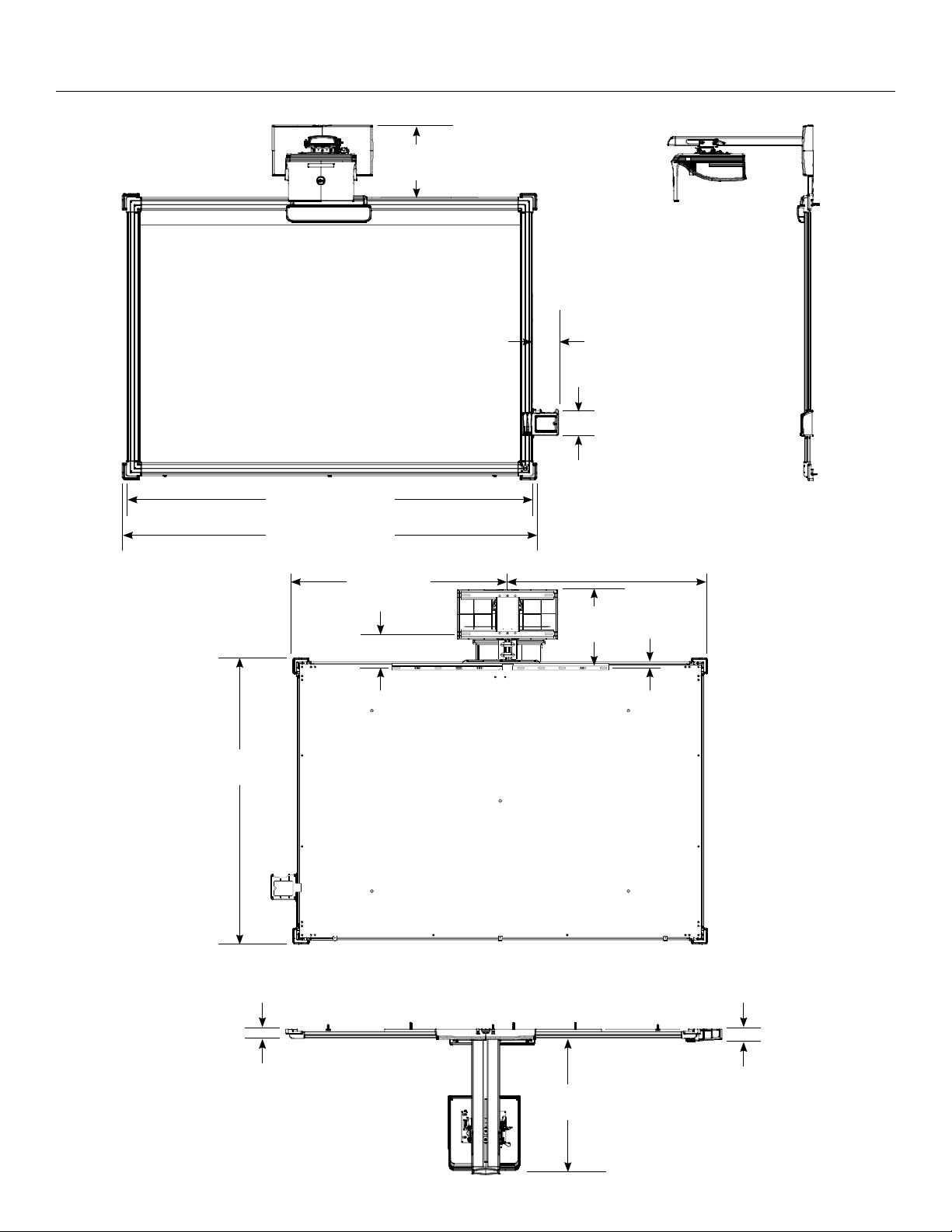
Product Dimensions
Front View
78.75 in. (2000.1 mm)
14.02 in.
(356.2 mm)
Side View
5.02 in.
(127.4 mm)
4.99 in.
(126.7 mm)
55.52 in.
(1410.1 mm)
80.37 in. (2041.4 mm)
41.60 in.
(1056.5 mm)
6.6 in. (167.52 mm)
38.77 in.
(984.8 mm)
15.23 in.
(386.8 mm)
1.21 in.
(30.65 mm)
Back View
1.67 in. (42.3 mm) 2.4 in. (60.9 mm)
Top View
28.07 in.
(712.9 mm)
3
Page 4
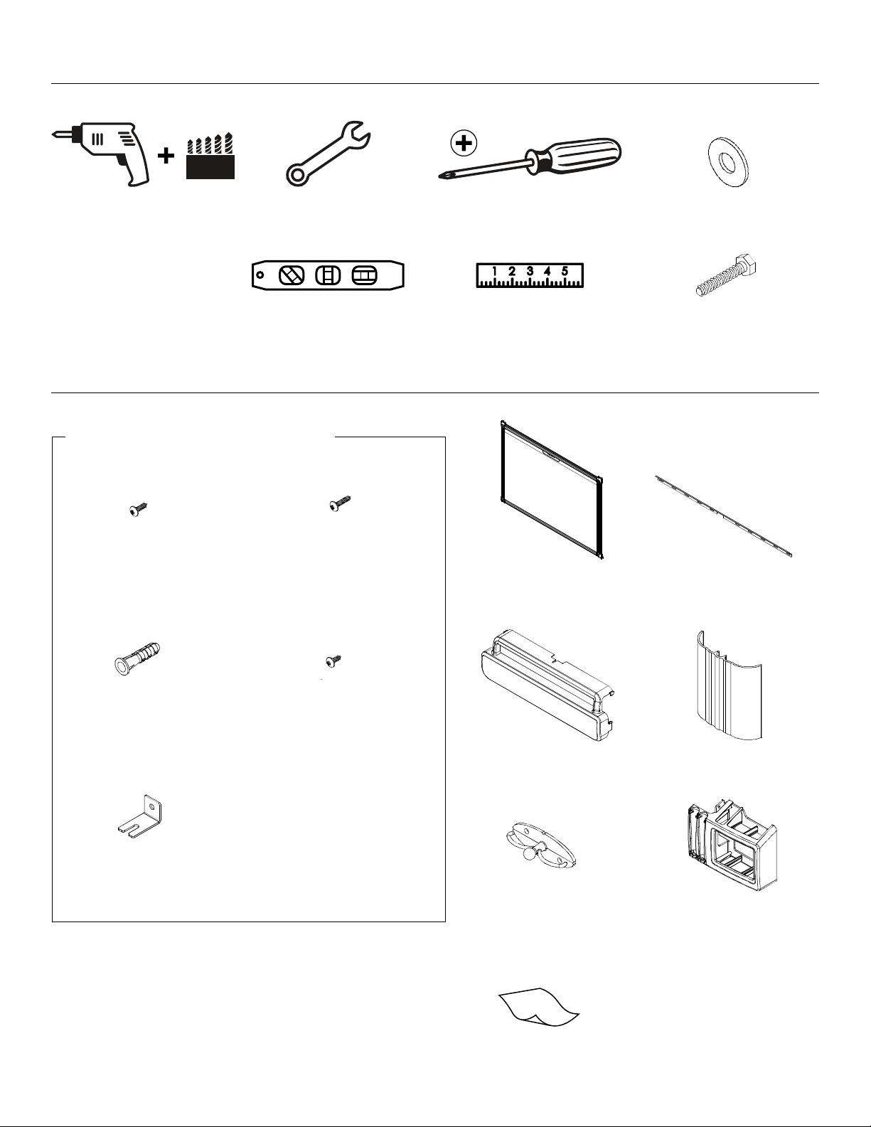
Tools Required for Installation
1/8 in. (wood)
1/2 in. (drywall)
8 mm (concrete)
6 mm (concrete –
AF6 toggler)
Parts
Included InstallationHardware
#8 x 3/4” Screw (1)
7/16” Wrench
Carpenter’s Level Ruler
#8 x 1” Screw (10)
#2 Phillips Screwdriver
Screen (1) Wall Bracket (1)
1/4” Washer (3)
1/4” x 1-1/2”
Lag Screw (3)
#8-10 Wall
Anchor (10)
Screen Bracket (5)
4
#8 X 1/2” Screw (7)
Sensor Cover (1)
Cable Cover
Clip (2)
Cleaning Cloth (1)
Cable Cover (1)
Marker Tray (1)
Page 5

Installation
1. Determine desired height of image (measured from oor)
(Figure 1).
2. Determine desired center of image area (Figure 1).
3. Measure 4-1/16” up from desired height (top) of image
and 4” to the right of center of screen and mark location
(Figure 1).
4. Determine location of studs behind drywall.
5. Drill one pilot hole into a wall stud at location
marked in Step 3 (Figure 1).
4 in.
4-1/16 in.
Height
from Floor
Center of
Screen
46-1/8 in.
73-3/4 in.
Studs
Floor
Figure 1
5
Page 6

Installation (continued)
NOTE: The (3) 1/4” x 1-1/2” bolts and (3) washers required in
Steps 6-8 are NOT INCLUDED with the screen/whiteboard
packaging.
6. Install (1) 1/4” x 1-1/2” bolt and (1) washer through middle
of bracket into previously drilled hole, leaving 1/2” of the
bolt extending from wall. Use carpenter’s level to make
sure bracket is properly level (Figure 2).
7. Position level on top of wall bracket. Move bracket until
level. Drill (2) holes for the other bolts in wall studs.
8. Install the other (2) 1/4” x 1-1/2” bolts and (2) 1/4” washers
in the previously drilled holes. Tighten all bolts against wall
bracket.
9. Measure down 52-1/4” on center and mark spot. Move
right and left of screen until wall studs are found and mark
(Figure 3).
Center of
Screen
Previously
Drilled Hole
Middle Fastener
Figure 2
Center of Screen
52-1/4 in.
Figure 3
6
Page 7

10. Install the (3) screen brackets using:
Wood or steel studs: (3) supplied #8 x 1” screws.
Concrete wall or no studs: (3) supplied #8-10 wall anchors
and (3) supplied #8 x 1” screws.
11. Install projector mount. Refer to the S520 Dual Stud Wall
Mount (MSP-DCCUST2) manual. Do not install
the (2) plastic covers for mount (Figure 4).
12. Run cables for projector up through hole in wall bracket and
cover to projector location (Figure 5).
Figure 4
Projector Signal Cable
IR Sensor Power
Projector Power Cord
Figure 5
7
Page 8

Installation (continued)
DETAIL E
SCALE 1 : 2
13. Mount screen onto wall bracket by hooking into the back groove of
the screen frame (Figure 6).
NOTE: The bumpers on the back side of the screen/whiteboard are
used to maintain planarity when pressure is applied to the projection
surface during usage. If the bumpers are obstructing installation on
your wall during Steps 13 and 14, they can be removed.
14. Secure bottom of screen to wall using (3) of the supplied #8 x 1/2”
screws through bottom brackets into the lower channel of the screen
frame (Figure 7).
15. Install the (2) top brackets (Figure 8) using:
Wood or steel studs: (2) supplied #8 x 1” screws.
Concrete wall or no studs: (2) supplied #8-10 wall anchors
and (2) supplied #8 x 1” screws.
16. Secure top of screen to wall using (2) of the supplied #8 x 1/2”
screws through top brackets into the top channel of the screen
(Figure 8).
Figure 6
Figure 7 Figure 8
E
8
Page 9

17. Secure marker tray to right side of screen frame
DETAIL F
SCALE 1 : 2
F
at desired height by using (2) of the supplied
#8 x 1/2” screws into the side channel of the
screen frame (Figure 9).
18. Secure marker tray (Figure 10) to wall using:
Wood or steel studs: (1) supplied #8 x 1” screw.
Concrete wall or no studs: (1) supplied #8-10 wall
anchor and (1) #8 x 1” screw.
19. Secure IR sensor bar (packaged with the S520
Projector) to screen by sliding it onto the metal
bracket. Insert safety screw through IR sensor
bar into bracket (Figure 11).
Attach marker
tray to frame with
(2) screws into the
side channel.
Figure 9
Safety
Screw
Figure 11Figure 10
9
Page 10

Installation (continued)
20. Attach sensor cover by snapping clips over screen frame.
Secure to frame by screwing down into the upper channel of
the screen frame with supplied #8 x 3/4” screw (Figure 12).
21. In between the projector mount and the IR sensor
cover, cable clips will be mounted to the wall for cable
management. Attach clips to the wall using:
Wood studs: (4) supplied #8 x 1” screws.
Concrete wall or no studs: (4) supplied #8-10
wall anchors and (4) supplied #8 x 1” screws.
When secure, route cables and cords behind the two cable
clips. Attach cable cover to the cable clips (Figure 13).
NOTE: Two cable clips are shipped with the screen/
whiteboard. For some installations, only one cable clip may
be needed.
22. Install projector mount covers and projector (Figure 14).
Refer to the S520 Dual Stud Wall Mount (MSP-DCCUST1)
manual.
DC Power
Cable for
Sensor
Figure 12
10
Figure 13
Figure 14
Page 11

Recommended Screen/Whiteboard
Markers
Recommended Screen/Whiteboard
Cleaning
This Dell S520 Screen/Whiteboard is a dual-purpose projection
screen and whiteboard. The surface of the screen/whiteboard
can be used with dry erase markers from a wide variety of
manufacturers and brands. Do not use permanent markers with
this product.
The supplied cleaning cloth can be used to clean marks on the
Dell S520 Screen/Whiteboard surface made by everyday dry
erase marker usage. To clean persistent marks from dry erase
markers, only use a standard dry erase marker cleaning solution
and the cleaning cloth. To clean permanent marks and other
unintentional marks on the surface, use a non-abrasive or nonscouring spray cleaning solution with the cleaning cloth or a
melamine foam cleaning pad.
11
Page 12

• 日本語の説明書は、http://
downloads.chiefmfg.com/MANUALS-I/PTDRV-
I.pdf をご覧ください。
• 访问 http://downloads.chiefmfg.com/MANUALS-
I/PTDRV-I.pdf 参考说明书译本。
• 如需翻譯版指示說明,請前往 http://
downloads.chiefmfg.com/MANUALS-I/PTDRV-
I.pdf。
• 번역된 안내서를 보려면 http://
downloads.chiefmfg.com/MANUALS-I/PTDRV-
I.pdf 을 ( 를 ) 방문하십시오 .
• โปรดเข้าไปที่ http://downloads.chiefmfg.com/
MANUALS-I/PTDRV-I.pdf
สําหรับคําแนะนําฉบับแปล
• Go to http://downloads.chiefmfg.com/MANUALS-
• 日本語の説明書は、http://
• Go to http://downloads.chiefmfg.com/MANUALS-
• 日本語の説明書は、http://
• Go to http://downloads.chiefmfg.com/MANUALS-
• 日本語の説明書は、http://
• Go to http://downloads.chiefmfg.com/MANUALS-
• 日本語の説明書は、http://
• Go to http://downloads.chiefmfg.com/MANUALS-
• 日本語の説明書は、http://
Installation Video
For further guidance and helpful information about installing an S520 Dual Stud Wall
Mount and S520 Screen/Whiteboard, please reference the installation video:
http://downloads.chiefmfg.com/MANUALS-I/Dell Interactive Solution.mp4
• Go to http://downloads.chiefmfg.com/MANUALSI/PTDRV-I.pdf for translated instructions.
• Entre en http://downloads.chiefmfg.com/
MANUALS-I/PTDRV-I.pdf para obtener las
instrucciones traducidas en su idioma.
• Bedienungsanleitungen in Ihrer Sprache finden
Sie auf http://downloads.chiefmfg.com/
MANUALS-I/PTDRV-I.pdf.
• Pour la traduction des instructions, allez à http://
downloads.chiefmfg.com/MANUALS-I/PTDRVI.pdf.
• Visitare il sito http://downloads.chiefmfg.com/
MANUALS-I/PTDRV-I.pdf per le istruzioni
tradotte.
• Visite http://downloads.chiefmfg.com/
MANUALS-I/PTDRV-I.pdf para obter instruções
traduzidas.
CW88R Rev. A00
24695 Rev00
http://
downloads.chiefmfg.com/MANUALS-I/PTDRVI.pdf をご覧ください。
访问 http://downloads.chiefmfg.com/MANUALSI/PTDRV-I.pdf 参考说明书译本。
http://
downloads.chiefmfg.com/MANUALS-I/PTDRVI.pdf。
번역된 안내서를 보려면 http://
downloads.chiefmfg.com/MANUALS-I/PTDRV-
I.pdf 을 ( 를 ) 방문하십시오 .
โปรดเข ้าไปที่ http://downloads.chiefmfg.com/
MANUALS-I/PTDRV-I.pdf
สําหรับคําแนะนําฉบับแปล
 Loading...