


Dell Neworking S4810–Open Networking
(ON) Installation Guide
July 2014

Notes, Cautions, and Warnings
NOTE: A NOTE indicates important information that helps you make better use of your computer.
CAUTION: A CAUTION indicates either potential damage to hardware or loss of data and tells you
how to avoid the problem.
WARNING: A WARNING indicates a potential for property damage, personal injury, or death.
Copyright © 2014 Dell Inc. All rights reserved. This product is protected by U.S. and international copyright and
intellectual property laws. Dell™ and the Dell logo are trademarks of Dell Inc. in the United States and/or other
jurisdictions. All other marks and names mentioned herein may be trademarks of their respective companies.
2014 - 07
Rev. A01

Contents
1 About this Guide....................................................................................................6
Information Symbols.............................................................................................................................6
Related Documents...............................................................................................................................7
2 The S4810–ON System........................................................................................8
Introduction...........................................................................................................................................8
Orderable S4810–ON Components...............................................................................................9
Prerequisite............................................................................................................................................9
Features............................................................................................................................................... 10
Ports.....................................................................................................................................................10
System Status.......................................................................................................................................10
LED Displays...................................................................................................................................10
3 Site Preparations................................................................................................. 13
Site Selection....................................................................................................................................... 13
Cabinet Placement.............................................................................................................................. 13
Rack Mounting.....................................................................................................................................14
Grounding (Optional).......................................................................................................................... 14
Fans and Airflow.................................................................................................................................. 14
Power...................................................................................................................................................14
Storing Components........................................................................................................................... 15
4 Install the S4810–ON........................................................................................ 16
Installing the S4810–ON Chassis in a Rack or Cabinet..................................................................... 16
Attaching the Mounting Brackets into a Two-Post Rack or Cabinet.......................................... 16
Installing the System into a Two-Post Rack or Cabinet...............................................................17
Attaching the Mounting Brackets into a Four-Post Rack or Cabinet..........................................18
Installing the System into a Four-Post Rack or Cabinet.............................................................. 19
Attaching the Ground Cable...............................................................................................................20
Installing the SFP+ and QSFP+ Optics................................................................................................21
Remove the SFP+ and QSFP+ Optics.......................................................................................... 22
Splitting QSFP+ Ports to SFP+ Ports.................................................................................................. 22
Supply Power and Power Up the System...........................................................................................22
AC Power.......................................................................................................................................22
After Installing the S4810–ON............................................................................................................23
5 Power Supplies....................................................................................................24
Components....................................................................................................................................... 24

Installing an AC Power Supply............................................................................................................25
Replacing an AC Power Supply.......................................................................................................... 26
6 Fans........................................................................................................................27
Components........................................................................................................................................27
Installing a Fan Module....................................................................................................................... 28
Replacing a Fan Module......................................................................................................................28
7 Console Ports...................................................................................................... 30
Accessing the RJ-45 Console Port (RS-232).....................................................................................30
Access the RJ-45 Console Port with a DB-9 Adapter....................................................................... 31
Before You Install an Operating System.............................................................................................31
ONIE Service Discovery.................................................................................................................31
8 Troubleshooting................................................................................................. 33
Command Line Interface Options......................................................................................................33
Viewing S4810-ON System Information............................................................................................33
Boot Processes....................................................................................................................................34
POST.............................................................................................................................................. 34
EDA (Quick Test Mode).................................................................................................................34
Restoring the S4810–ON Factory Defaults..................................................................................35
Capture Support Data from ONIE.................................................................................................35
Downloading the Diagnostic Package............................................................................................... 35
Troubleshooting Tools........................................................................................................................37
edatool...........................................................................................................................................38
pcitool............................................................................................................................................39
i2ctool............................................................................................................................................40
memtool........................................................................................................................................40
pltool..............................................................................................................................................42
gpiotool......................................................................................................................................... 45
storagetool.................................................................................................................................... 45
psutool...........................................................................................................................................46
fantool........................................................................................................................................... 46
temptool........................................................................................................................................ 47
nvramtool...................................................................................................................................... 47
Troubleshooting Issues for the S4810–ON System.......................................................................... 47
9 Specifications......................................................................................................49
Chassis Physical Design......................................................................................................................49
IEEE Standards...............................................................................................................................50
Agency Compliance............................................................................................................................50
USA Federal Communications Commission (FCC) Statement................................................... 50

European Union EMC Directive Conformance Statement..........................................................50
Japan: VCCI Compliance for Class A Equipment.........................................................................51
Korean Certification of Compliance.............................................................................................52
Safety Standards and Compliance Agency Certifications........................................................... 52
Electromagnetic Compatibility (EMC).......................................................................................... 52
Product Recycling and Disposal................................................................................................... 53
Removing the SD Card..................................................................................................................54
Replacing the Battery on the S4810–ON.....................................................................................54
10 Technical Support............................................................................................ 58
The iSupport Website..........................................................................................................................58
Accessing iSupport Services......................................................................................................... 58
Contacting the Technical Assistance Center.....................................................................................58
Requesting a Hardware Replacement................................................................................................59
1
About this Guide
This guide provides site preparation recommendations, step-by-step procedures for rack mounting and
desk mounting, inserting optional modules, and connecting to a power source.
.
CAUTION: To avoid electrostatic discharge (ESD) damage, wear grounding wrist straps when
handling this equipment.
WARNING: Only trained and qualified personnel can install this equipment. Read this guide
before you install and power up this equipment. This equipment contains two power cords.
Disconnect both power cords before servicing.
WARNING: This equipment contains optical transceivers, which comply with the limits of Class 1
laser radiation.
WARNING: When no cable is connected, visible and invisible laser radiation may be emitted from
the aperture of the optical transceiver ports. Avoid exposure to laser radiation and do not stare
into open apertures.
Information Symbols
This book uses the following information symbols:
NOTE: The Note icon signals important operational information.
CAUTION: The Caution icon signals information about situations that could result in equipment
damage or loss of data.
WARNING: The Warning icon signals information about hardware handling that could result in
injury.
WARNING: The ESD Warning icon requires that you take electrostatic precautions when handling
the device.
6
About this Guide

Related Documents
For more information about the S4810–ON system, refer to the Dell Networking S4810–Open
Networking (ON) Getting Started Guide.
NOTE: For the most recent documentation, visit iSupport: http://www.dell.com/support/my-
support.
About this Guide
7
2
The S4810–ON System
The following sections describe the Dell Networking S4810–ON system.
Introduction
The Dell Networking S4810–ON platform is a next-generation switch/router designed to meet the
requirements for distributed data center cores.
It is a one-rack unit (RU) chassis that supports 48 ports of 10GbE small form-factor pluggable plus (SFP+)
and four quad small form-factor pluggable plus (QSFP+) ports. For system access, the S4810–ON
includes an RS-232/RJ-45 console port and a management port for system access.
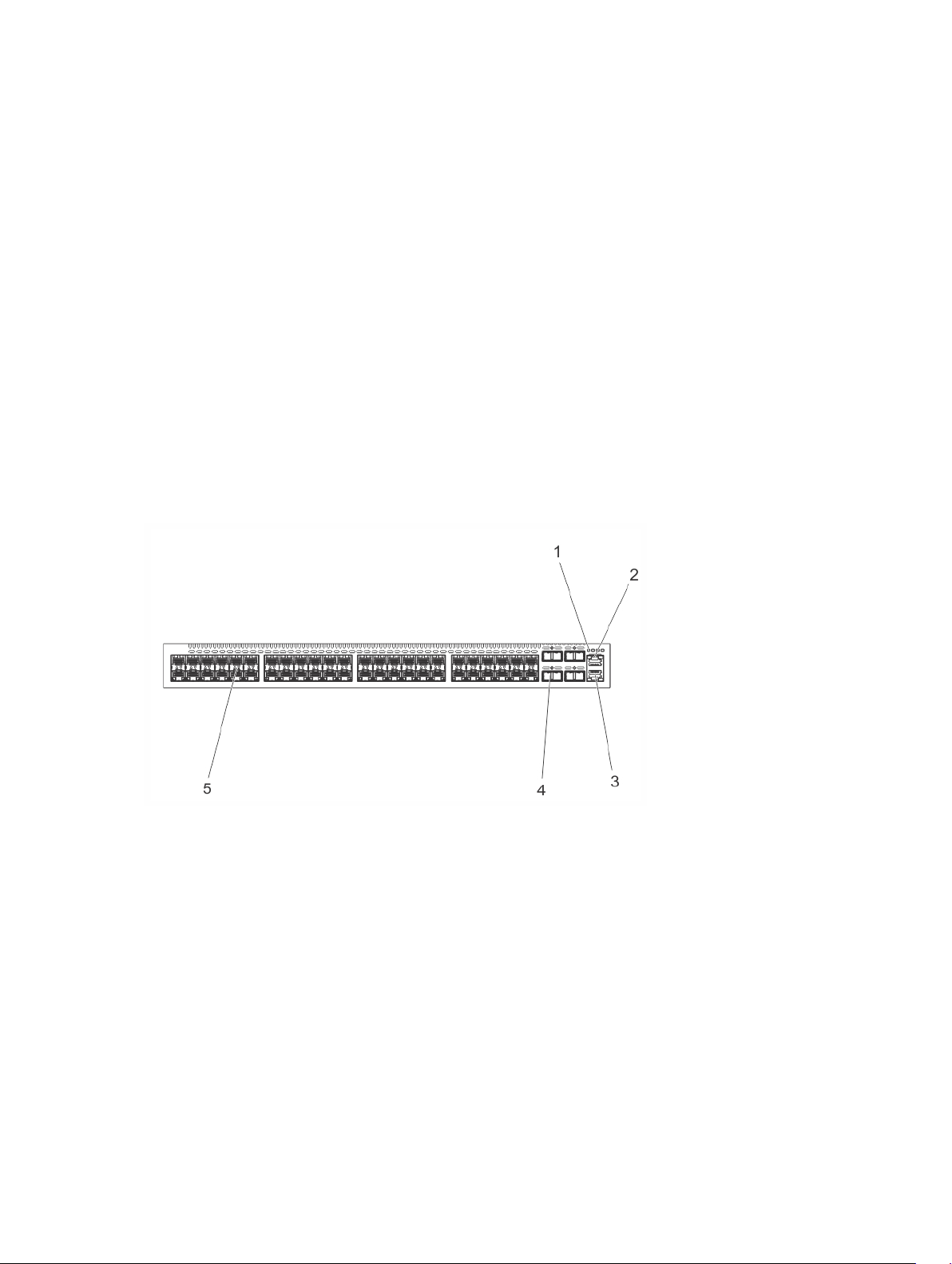
The S4810–ON input/output (I/O) side (shown in the following illustration) contains the 48 ports of
10GbE and four uplink ports of 40GbE QSFP+ autosensing ports and management ports.
Figure 1. S4810–ON I/O-Side View
1. System LEDs
2. RS-232/RJ-45 Console Port
3. Management (Ethernet) Port
4. 40GE QSFP+ Ports
5. 10GE SFP+ Ports
The S4810–ON power supply unit (PSU) side (shown in the following illustration) contains the PSU and
fan modules.
8
The S4810–ON System

Figure 2. S4810–ON PSU-Side View
1. Mounting Bracket
2. Fan Module 1
3. Fan Module 2
4. Mounting Bracket
5. Power Supply (PSU2)
6. Power Supply (PSU1)
7. Grounding Screw
Orderable S4810–ON Components
You can order the S4810–ON system in several different configurations. You can also order optional
modules and optics separately.
You can order the following supported hardware components.
• 48-port 10G SFP+ with four QSFP+, 40G ports, one AC power supply and two fan subsystems (airflow
from I/O side to power supply side)
• 48-port 10G SFP+ with four QSFP+, 40G ports, one AC power supply and two fan subsystems (airflow
from power supply side to I/O side)
• S4810–ON Series — Fan with airflow from the I/O side to the PSU side
• S4810–ON Series — Fan with airflow from the PSU side to the I/O side
• S4810–ON Series — AC Power supply with airflow from the I/O side to the PSU side
• S4810–ON Series — AC Power supply with airflow from the PSU side to the I/O side
For a list of supported optics, refer to the S4810–ON data sheet at http://www.dell.com or contact your
Dell Networking representative.
Prerequisite
To successfully install the S4810–ON, ensure that you have the following components.
• S4810–ON chassis
• At least one grounded AC power source per chassis
• Cable to connect the AC power source to the chassis (US power cables included)
• Mounting brackets for rack installation (included)
• Screws for rack installation and #1 and #2 Phillips screwdrivers (not included)
The S4810–ON System
9

• Ground cable (not included, optional)
• Ground cable screws (included)
• Copper/fiber cables
Other optional components are:
• Additional power supply unit
• Additional fan module
• Additional mounting brackets (if installing in a four-post rack or cabinet)
Features
The S4810–ON offers the following features.
• S4810–ON CPU and switch processor
• Hot-swappable redundant power supply
• 19 inch rack-mountable
• Standard 1U chassis height
Ports
The S4810–ON offers the following ports.
• External Serial RS-232 port (RJ45 type)
• Remote management port
• 48–ports 10GbE and 4–ports 40GbE
• Universal serial bus (USB)-A port
• USB-B port
System Status
You can view S4810–ON status information using the light emitting diodes (LEDs).
LED Displays
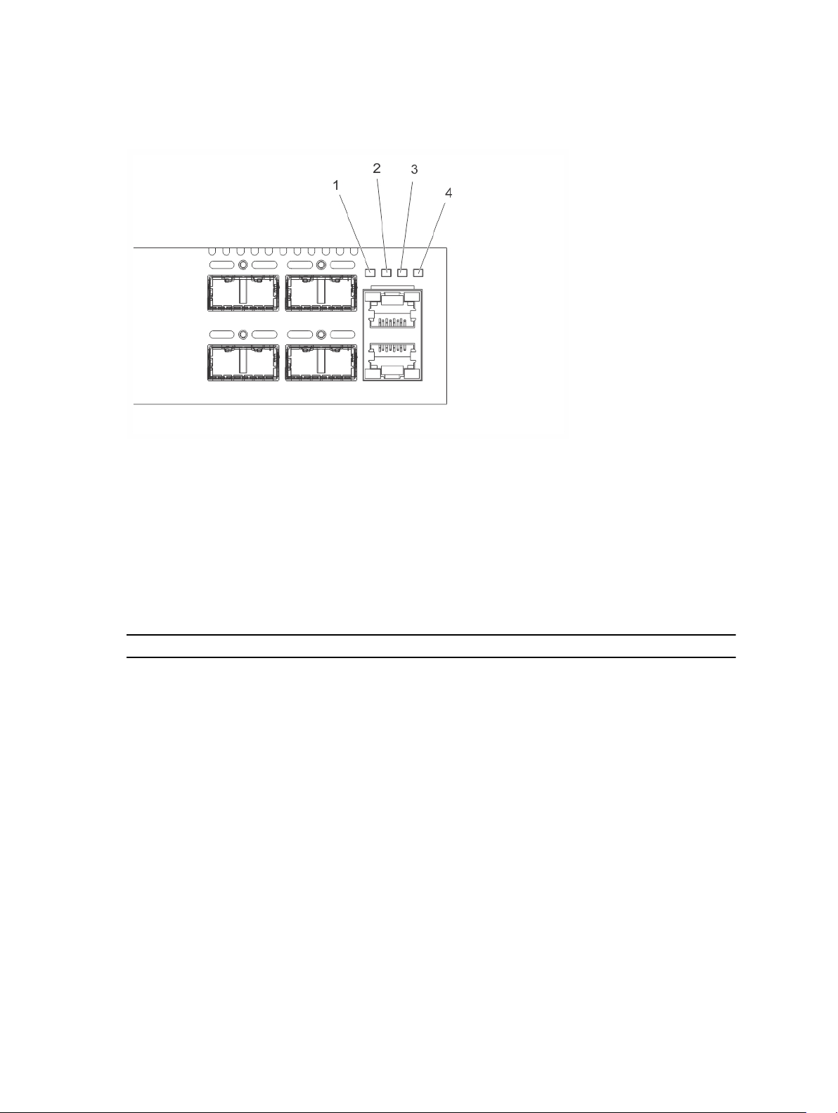
The S4810–ON includes LED displays on the I/O side of the chassis (shown in the following illustration).
When the S4810–ON powers up or reloads, the PSU LED is solid green. For additional LED information,
refer to your third-party operating software documentation.
The S4810–ON system LEDs are:
• System status (SYS)
• Stack Master indicator (MASTER)
• Fan status (FAN)
• Power status (PSU)
Additionally, the PSUs and fans have LEDs that indicate their individual status:
• PSU status
10
The S4810–ON System
• Fan tray status
• System
Figure 3. S4810–ON LEDs
1. SYS
2. MASTER
3. FAN
4. PSU
LED Behavior on the S4810–ON System
The following S4810–ON system LED behavior is seen during U-Boot and ONIE operations.
Table 1. S4810–ON LED Behavior
LED Description
System Status LED
Master LED
Fan LED
Power Status LED
• Off — no power
• Blinking green — booting or system is in
Diagnostic mode
• Solid green — normal operation
• Solid red — critical alarm
• Blinking red — non-critical alarm
• Solid green — system is in Stacking Master
mode
• Off — System is in Slave mode
• Solid green — Fan is powered on and running
at the expected RPM
• Solid yellow — Fan failed including
incompatible airflow direction
• Off — no power
• Solid green — normal operations
The S4810–ON System
11

LED Description
• Blinking yellow — one power supply has failed
12
The S4810–ON System

3
Site Preparations
The S4810–ON is suitable for installation as part of a common bond network (CBN).
You can install the system in:
• network telecommunication facilities
• data centers
• other locations where the National Electric Code (NEC) applies
For more information about S4810–ON specifications, refer to Specifications.
NOTE: Install the S4810–ON system into a rack or cabinet before installing any optional
components.
Site Selection
Install Dell Networking equipment in restricted access areas.
A restricted access area is one in which service personnel can only gain access using a special tool, lock,
key or other means of security and access is controlled by the authority responsible for the location.
Ensure that the area where you install your S4810–ON system meets the following safety requirements:
• Near an adequate power source. Connect the system to the appropriate branch circuit protection as
defined by your local electrical codes.
• Environmental temperature between 32° to 104°F (from 0° to 40°C).
• Relative humidity that does not exceed 85 percent noncondensing.
• In a dry, clean, well-ventilated and temperature-controlled room, away from heat sources such as hot
air vents or direct sunlight.
• Away from sources of severe electromagnetic noise.
• Positioned in a rack or cabinet, or on a desktop with adequate space in the front, rear, and sides of the
S4810–ON for proper ventilation and access.
Cabinet Placement
Install the S4810–ON only in indoor cabinets designed for use in a controlled environment.
Do not install the S4810–ON in outside plant cabinets. For cabinet placement requirements, refer to Site
Selection.
The cabinet must be a minimum cabinet size. Airflow must be according to the Electronic Industries
Alliance (EIA) standard. Ensure that there is a minimum of 5 inches (12.7 cm) between the intake and
exhaust vents and the cabinet wall.
Site Preparations
13

Rack Mounting
When you prepare your equipment rack, ensure that the rack is earth ground.
Ground the equipment rack to the same ground point the power service in your area uses. The ground
path must be permanent.
Grounding (Optional)
Use the S4810–ON in a common bond network (CBN).
Connect the grounding cables as described in Install the S4810-ON.
Fans and Airflow
The S4810–ON fans support two airflow options.
Be sure to order the fans suitable to support your site’s ventilation. Use a single type of airflow fan in your
system. Do not mix reverse and normal airflows in a single S4810–ON chassis.
• Normal — airflow is from the I/O panel to the power supply. The grab-handle is labeled Exhaust.
• Reversed — airflow is from the power supply to the I/O panel. The grab-handle is labeled Intake.
For proper ventilation, position the S4810–ON in an equipment rack (or cabinet) with a minimum of 5
inches (12.7 cm) of clearance around the exhaust vents. When you install two S4810–ON systems near
each other, position the two chassis at least 5 inches (12.7 cm) apart to permit proper airflow. The
acceptable ambient temperature ranges are listed in Specifications.
The fan speed increases and decreases automatically based on the system’s state and temperature. The
switch never intentionally turns off the fans.
Power
To connect the chassis to the applicable power source, use the appropriate power cord with the S4810–
ON. An AC power cord is included with the system.
When installing AC systems, follow the requirements of the National Electrical Code, ANSI/NFPA 70
where applicable.
The system is powered-up as soon as the power cord is connected between the system and the power
source.
CAUTION: Always disconnect the power cable before you service the power supply slots.
CAUTION: Use the power supply cord as the main disconnect device on the AC system. Ensure
that the socket-outlet is located/installed near the equipment and is easily accessible.
14
Site Preparations

Storing Components
If you do not install your S4810–ON and components immediately, Dell Networking recommends
properly storing the system and all optional components until you are ready to install them.
WARNING: ESD damage can occur when components are mishandled. Always wear an ESDpreventive wrist or heel ground strap when handling the S4810–ON and its accessories. After you
remove the original packaging, place the S4810–ON and its components on an antistatic surface.
Follow these storage guidelines:
• Storage temperature must remain constant ranging from -40° to 158°F (from -40°C to 70°C).
• Store on a dry surface or floor, away from direct sunlight, heat, and air conditioning ducts.
• Store in a dust-free environment.
Site Preparations
15

4
Install the S4810–ON
To install the S4810–ON system, Dell Networking recommends completing the installation procedures in
the order presented in this chapter.
Always handle the S4810–ON and its components with care. Avoid dropping the system or its field
replaceable units (FRUs).
This chapter describes the installation procedures as follows:
1. Installing the S4810–ON Chassis in a Rack or Cabinet
a. Attaching the Mounting Brackets into a Two-Post Rack or Cabinet
b. Installing the System into a Two-Post Rack or Cabinet
c. Attaching the Mounting Brackets into a Four-Post Rack or Cabinet
d. Installing the System into a Four-Post Rack or Cabinet
2. Attaching the Ground Cable
3. Installing the SFP+ and QSFP+ Optics
4. Splitting QSFP+ Ports to SFP+ Ports
5. Supply Power and Power Up the System
6. After Installing the S4810-ON
WARNING: ESD damage can occur if components are mishandled. Always wear an ESDpreventive wrist or heel ground strap when handling the S4810–ON and its components. As with
all electrical devices of this type, take all the necessary safety precautions to prevent injury when
installing this system.
Installing the S4810–ON Chassis in a Rack or Cabinet
The following sections describe how to install the S4810–ON in a rack or cabinet.
Attaching the Mounting Brackets into a Two-Post Rack or Cabinet
The S4810–ON ships with mounting brackets (rack ears) and the required screws for a two-post rack or
cabinet installation. The brackets are sent in a package with the system.
NOTE: Dell Networking recommends attaching the brackets at the power supply unit (PSU) side.
This set up provides the greatest weight support for the chassis in the rack or cabinet.
To attach the brackets to the system, follow these steps.
1. Take the brackets and screws out of their packaging.
2. Attach the brackets to the PSU sides of the system using four screws for each bracket. Attach the
bracket so that the “ear” is parallel to the PSU and the outside of the system.
16
Install the S4810–ON
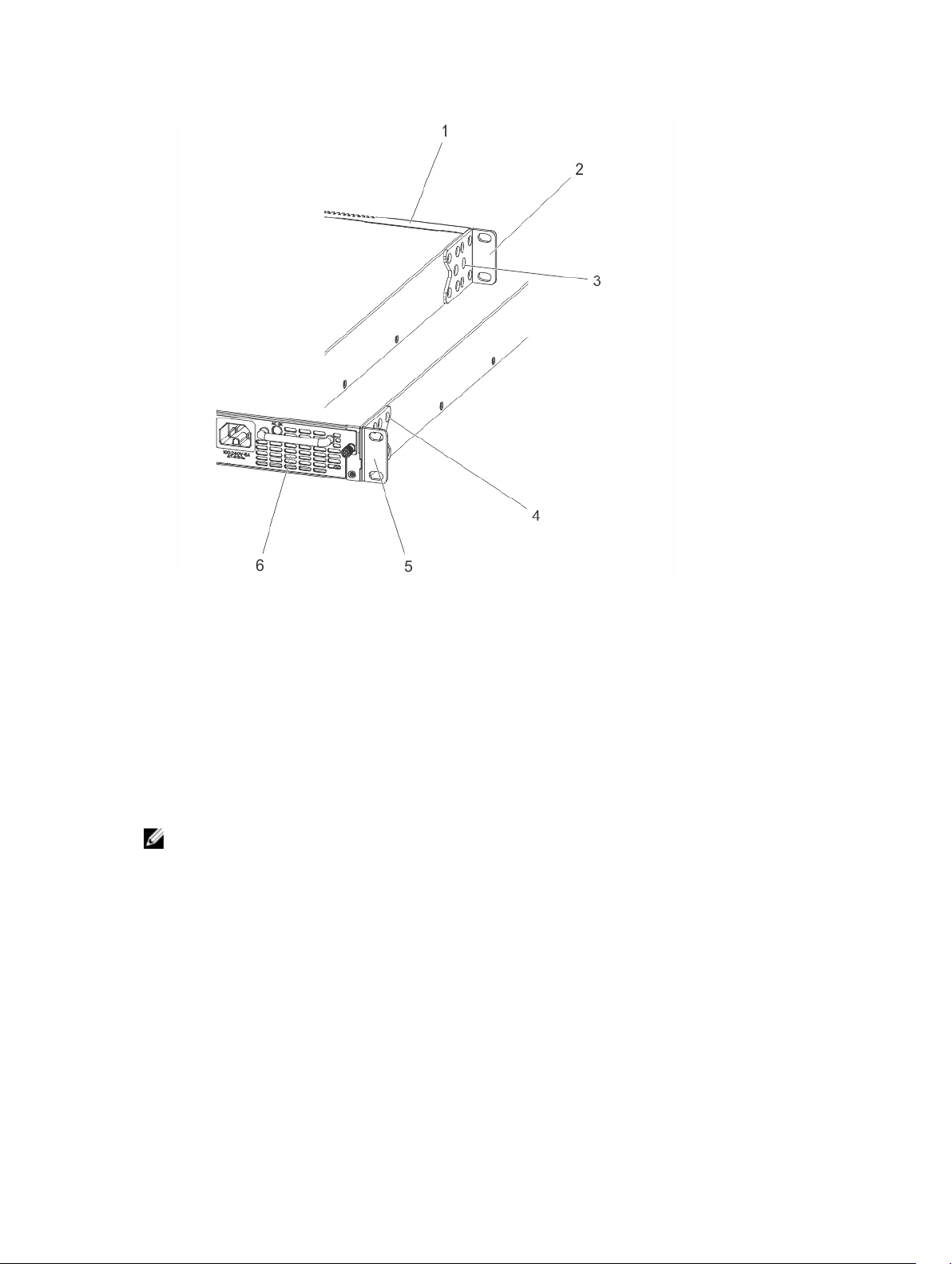
Figure 4. Attaching Mounting Brackets into a Two-Post Rack or Cabinet
1. View from the chassis I/O side 2. Connect to the Rack or Cabinet (ears)
3. Screws 4. Screws
5. Connect to the Rack or Cabinet (ears) 6. Power Supply
Installing the System into a Two-Post Rack or Cabinet
Ensure that there is adequate clearance surrounding the rack or within the cabinet to permit access and
airflow.
To install a system into a two-post 19-inch equipment rack using the already attached mounting
brackets, follow these steps.
NOTE: Dell Networking recommends using one person to hold the S4810–ON chassis in place
while another person attaches the brackets to the posts.
Attach the bracket “ears” to the rack or cabinet posts using the two screws for each bracket. Ensure
the screws are tightened firmly.
Install the S4810–ON
17
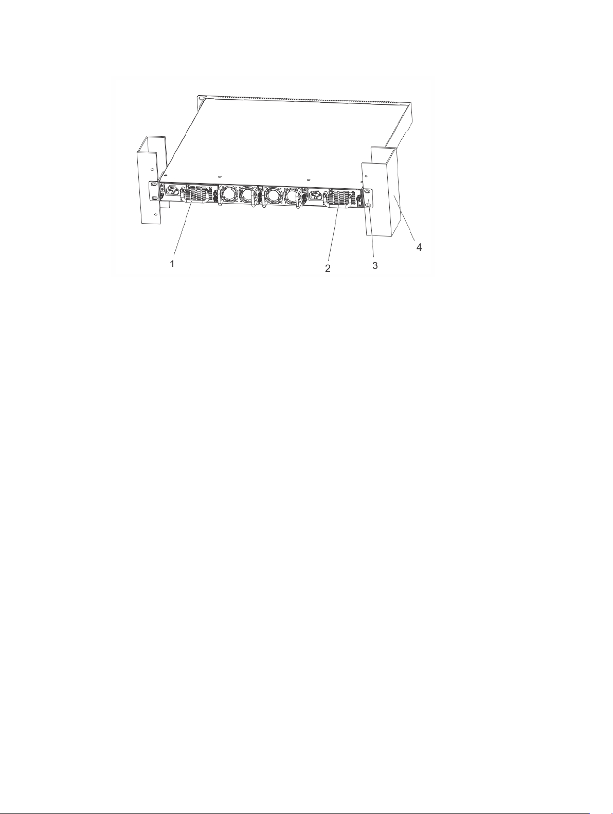
Figure 5. Installing the System into a Two-Post Rack or Cabinet
1. PSU1 2. PSU2
3. Rack Mounting Ears 4. Rack or Cabinet Post
Attaching the Mounting Brackets into a Four-Post Rack or Cabinet
The S4810–ON ships with mounting brackets (rack ears) and the required screws for a two-post rack or
cabinet installation.
To install the S4810–ON in a four-post rack or cabinet, you must order additional brackets separately.
Use the brackets included with the S4810–ON on the I/O side of system and use the brackets you
ordered separately on the PSU side of the system.
Unlike the two-post installation, the four-post installation requires attaching brackets to the rack prior to
installing the system.
To attach the brackets to the rack or cabinet, follow these steps.
1. Ensure that there is adequate clearance surrounding the rack or within the cabinet to permit access
and airflow.
2. Take the brackets and screws out of their packaging.
3. Attach the brackets to the PSU sides of the chassis using four screws for each bracket. Attach the
bracket so that the “ear” is parallel to the PSU and the outside of the chassis.
18
Install the S4810–ON

Figure 6. Attaching the Mounting Brackets into a Four-Post Rack or Cabinet
1. View from the chassis I/O side 2. Connect to the rack or cabinet
3. Screws 4. Screws
5. Connect to the rack or cabinet (ears) 6. Power Supply
4. Attach the long bracket to each side of the chassis using the provided countersink screws. Use two
screws on each side of the chassis.
5. Install the rack mount ears into the I/O-facing posts using rack mount screws (not included with the
system).
NOTE: Mount the rack mount ears so that the system is level when fully installed.
6. Using the provided pan head screws, attach the rack ears on the I/O facing posts to the long bracket
(attached to the system). To secure, tighten the pan head screws.
Installing the System into a Four-Post Rack or Cabinet
To install a system into a four-post equipment rack using the already attached mounting brackets, follow
these steps.
1. Ensure that there is adequate clearance surrounding the rack or within the cabinet to permit access
and airflow.
2. Install the system into the rack. Ensure the long brackets dock into the previously installed rack ears.
3. Fasten the system to the PSU-facing posts using rack mount screws (not included with the system).
Install the S4810–ON
19

Figure 7. Installing the System into a Four-Post Rack or Cabinet
1. I/O Side 2. Rack Ears
3. Long Brackets 4. Rack Ears
5. PSU Side
4. Use the provided pan head screws to attach the rack ears on the I/O-facing posts to the long bracket
previously attached to the system. Tighten the pan head screws to secure the system.
Attaching the Ground Cable
To attach the ground cable to the chassis, use a single M4x0.7 screw.
The cable itself is not included with the S4810–ON. To properly ground the chassis, Dell Networking
recommends using a 6AWG one-hole lug, #10 hole size, 63" spacing (not included in shipping). The onehole lug must be a UL recognized, crimp-type lug.
NOTE: The rack installation “ears” are not suitable for grounding.
CAUTION: Grounding conductors must be made of copper. Do not use aluminum conductors.
To connect the ground cable to the system, follow these steps.
NOTE: Coat the one-hole lug with an anti-oxidant compound prior to crimping. Also, bring any unplated mating surfaces to a shiny finish and coat with an anti-oxidant prior to mating. Plated mating
surfaces must be clean and free from contamination.
1. Take the one M4x0.7 screw from the package.
2. Cut the cable to the desired length. The cable length must facilitate proper operation of the fault
interrupt circuits. Dell Networking recommends using the shortest cable route allowable.
3. Attach the one-hole lug to the chassis using the supplied 10-32 screw with the captive internal tooth
lock washer. Torque the screw to 20 in-lbs.
20
Install the S4810–ON

Figure 8. Attaching the Ground Cable
a. Lug hole
b. Ground Screw
4. Attach the other end of the ground cable to a suitable ground point. The rack installation ears are not
a suitable grounding point.
Installing the SFP+ and QSFP+ Optics
The S4810–ON has 48 SFP+ optical ports and four QSFP+ optical ports.
WARNING: ESD damage can occur if components are mishandled. Always wear an ESDpreventive wrist or heel ground strap when handling the S4810–ON and its components.
WARNING: When working with optical fibers, follow all warning labels and always wear eye
protection. Never look directly into the end of a terminated or unterminated fiber or connector
as it may cause eye damage.
To install SFP+ or QSFP+ optics into an open port, follow these steps:
1. Position the optic so it is in the correct position. The optic has a key that prevents it from being
inserted incorrectly.
2. Insert the optic into the port until it gently snaps into place.
NOTE: Both rows of QSFP+ ports require that the 40G optics be inserted with the tabs facing
up.
Install the S4810–ON
21

Remove the SFP+ and QSFP+ Optics
Remove an optic by pushing the tab on the optic and sliding the optic from the port.
When removing optics with direct attach cables (DACs) from the port, pull the release tab firmly and
steadily. Prior to pulling the release tab, you may need to gently push the optic into the port to ensure it is
seated properly. Do not jerk or tug repeatedly on the tab.
Splitting QSFP+ Ports to SFP+ Ports
The S4810–ON supports splitting a single 40G QSFP+ port into four 10G ports using one of the
supported breakout cables.
Supply Power and Power Up the System
Supply power to the S4810–ON after it is mounted in a rack or cabinet.
Dell Networking recommends re-inspecting your system prior to powering up. Verify that:
• the equipment is properly secured to the rack and properly grounded.
• the equipment rack is properly mounted and grounded.
• the ambient temperature around the unit (which may be higher than the room temperature) is within
the limits specified for the S4810–ON.
• there is sufficient airflow around the unit.
• the input circuits are correctly sized for the loads and that you use sufficient over-current protection
devices.
• all protective covers are in place.
• blank panels are installed if you do not install optional modules.
NOTE: A US AC power cable is included for powering up an AC power supply. You must order all
other power cables separately.
NOTE: ESD damage can occur if components are mishandled. Always wear an ESD-preventive wrist
or heel ground strap when handling the S4810–ON system and its components.
AC Power
To add AC power, connect the power cord plug to each AC power connector. Make sure that the power
cord is secure (as shown in the following illustration).
CAUTION: Ensure that you correctly install the PSU. When correctly installed, the AC power
connector is on the left side of the PSU and the status LED is at the top of the PSU (as shown in
the following illustration).
As soon as the cable is connected between the S4810–ON and the power source, the system is
powered-up; there is no on/off switch.
22
Install the S4810–ON

Figure 9. AC Power Connection
1. Power Connection
2. LED
After Installing the S4810–ON
After you have securely installed and powered on the S4810-ON, to configure your system, refer to your
open network installation environment (ONIE)-compatible third-party operating system documentation
at http://onie.org.
Install the S4810–ON
23

5
Power Supplies
The S4810–ON supports two hot-swappable power supply units (PSUs) with integrated fans that provide
cooling for the system.
The S4810–ON supports AC power supplies with two air-flow directions (normal and reversed). Two
PSUs are required for full redundancy, but the system can operate with a single PSU.
NOTE: If you use a single PSU, install a blank plate in the other PSU slot. Dell Networking
recommends using power supply 2 (PSU2) as the blank plate slot.
The PSUs are field replaceable. When running with full redundancy (two power supplies installed and
running), you can remove and replace one PSU while the other PSU is running without disrupting traffic.
The power supply LED indicates the power supply status:
• Off — no power
• Solid Green — Power supply is present and working
WARNING: ESD damage can occur if components are mishandled. Always wear an ESDpreventive wrist or heel ground strap when handling the S4810–ON and its components.
WARNING: To prevent electrical shock, ensure that the S4810–ON is grounded properly. If you
ground your equipment incorrectly, excessive emissions may result. To ensure that the power
cables meet your local electrical requirements, use a qualified electrician.
Components
The following power supply options are available for the S4810–ON.
• AC power supply with integrated fan
• AC power supply with integrated reverse flow fan
Power supply 1 (PSU1) is on the left side of the chassis; power supply 2 (PSU2) is on the right side of the
chassis.
The PSUs in the S4810–ON are field replaceable. When both power supplies are installed and running,
you can remove one power supply without interrupting traffic.
The PSUs are in a single piece with the PSU fans. You can replace the fan trays individually, but you
cannot replace the fans that are attached to the PSUs — if the fans attached to the PSU fail, you must
replace the entire PSU. For fan tray replacement procedures, refer to Fans.
WARNING: Prevent exposure and contact with hazardous voltages. Do not attempt to operate
this system with the safety cover removed.
CAUTION: Remove the power cable from the PSU prior to removing the PSU. Also, do not
connect the power cable before you insert the PSU in the chassis.
24
Power Supplies

NOTE: To comply with the GR-1089 Lightning Criteria for Equipment Interfacing with AC Power
Ports, use an external SPD at the AC input of the router.
Installing an AC Power Supply
To install an AC power supply, follow these steps.
NOTE: The PSU slides into the slot smoothly. Do not force a PSU into a slot as this action may
damage the PSU or the S4810–ON chassis.
NOTE: Ensure that the PSU is correctly installed. When the PSU is correctly installed, the power
connector is on the left side of the PSU and the status LED is at the top of the PSU (refer to the
following illustration).
Figure 10. Installing an AC Power Supply
1. PSU1
2. Fan Module
3. Fan Module
4. Cable Connector
5. PSU2
6. Grab Handle
NOTE: If you use a single PSU, you must install a blank plate in the other PSU slot. Dell Networking
recommends using power supply 2 (PSU2) as the blank plate slot.
1. Take the PSU out of the shipping box.
2. Use the grab handle to slide the PSU into the power supply bay.
3. Tighten the securing screw on the side of the PSU. Ensure that the PSU is secure.
4. Attach the power cables.
NOTE: The system powers up as soon as the cables are connected between the power supply
and the power source.
Power Supplies
25

Replacing an AC Power Supply
To replace an AC power supply, follow these steps:
NOTE: The PSU slides into the slot smoothly. Do not force a PSU into a slot as this action may
damage the PSU or the S4810–ON chassis.
NOTE: If a PSU fails, you must completely replace it. There are no field serviceable components in
the PSU. To request a hardware replacement, refer to Technical Support.
NOTE: If you use a single PSU, you must install a blank plate in the other PSU slot. Dell Networking
recommends using power supply 2 (PSU2) as the blank plate slot.
1. Disconnect the power cable from the PSU.
2. Use the grab handle to slide the PSU out of the power supply bay.
3. Use the grab handle on the replacement PSU to slide it into the power supply bay.
4. Tighten the securing screws on the replacement PSU with a screwdriver. Ensure that the PSU is
secure.
5. Attach the power cord to the replacement PSU.
The system powers up as soon as the cables are connected between the power supply and the
power source.
26
Power Supplies

6
Fans
The S4810–ON comes from the factory with one power supply unit (PSU) and two fan modules installed
in the system.
If two or more fans are installed and running, the fan modules are hot-swappable.
NOTE: To run the system, both slots must have operating fan units. If a module is not installed in
each slot (either as part of the PSU or as an independent fan module), the system shuts down in one
minute.
In addition to the integrated fan/power supply modules, you can order and install fan modules separately.
The S4810–ON supports two airflow direction options. Do not mix airflow types in a chassis; you can use
only a single airflow direction in a chassis.
• Normal — airflow is from the I/O panel to the PSU
• Reversed — airflow is from the PSU to the I/O panel
Environmental factors can decrease the amount of time required between fan replacements. Check the
environmental factors regularly. An increase in temperature and/or particulate matter in the air might
affect performance (for example, new equipment installation).
CAUTION: Check the fans at six-month intervals and replace them as necessary. Regularly
monitor the speeds of the cooling fans in order to accurately determine replacement intervals.
Components
The following are the S4810–ON fan components.
• S4810–ON Fan module
• S4810–ON Fan module - Reverse flow
Fans
27

Figure 11. S4810–ON Fan Module
1. PSU1
2. Fan Module 1
3. Fan Module 2
4. Grab Handle
5. PSU2
Installing a Fan Module
The fan modules in the S4810–ON are field replaceable.
Module slot 0 is on the left side of the chassis; module slot 1 is on the right side of the chassis.
CAUTION: DO NOT mix airflow directions. Both fans must use the same airflow direction (reverse
or normal).
To install a fan module, follow these steps.
1. Take the fan module out of the shipping box.
2. Use the grab handle to slide the fan module into the bay.
3. Tighten the securing screws on the sides of the fan module.
Replacing a Fan Module
To replace a fan module, follow these steps.
1. Loosen the securing screws on the sides of the fan module.
CAUTION: You must complete steps 2 and 3 within one minute or the system powers down.
2. Use the grab handle to slide the fan module out of the bay.
3. Use the grab handle on the replacement module to slide it into the bay.
28
Fans

4. Tighten the captive screws on the replacement module with a screwdriver. Ensure that the module is
secure.
Fans
29

Console Ports
You can access the S4810–ON directly through the console port at the input/output (I/O) side of the
system.
Accessing the RJ-45 Console Port (RS-232)
The RS-232/RJ-45 console port is labeled on the upper-right-hand side of the S8410–ON chassis (the
I/O side) (as shown in the following illustration).
NOTE: Before starting this procedure, be sure that you have a terminal emulation program already
installed on your PC.
7
Figure 12. S4810–ON Serial Console Port Connector
1. RJ-45 Console Port
The following table lists the console port pinout assignments.
To access the console port, follow these steps.
1. Install an RJ-45 copper cable into the console port. Use a rollover cable to connect the S4810–ON
console port to a terminal server.
2. Connect the other end of the cable to the dumb terminal emulator (DTE) server.
3. Keep the default terminal settings on the console as follows:
• 115200 baud rate
• No parity
• 8 data bits
• 1 stop bit
30
Console Ports

• No flow control
Access the RJ-45 Console Port with a DB-9 Adapter
If the DTE has a DB-9 interface, you can connect to the console using an RJ-45 to DB-9 adapter along
with the RJ-45 rollover cable.
The following table lists the pin assignments.
Table 2. Pin Assignments Between the Console and a DTE Terminal Server
Console Port RJ-45 to RJ-45
Rollover Cable
Signal RJ-45 Pinout RJ-45 Pinout DB-9 Pin Signal
RTS 1 8 8 CTS
NC 2 7 6 DSR
TxD 3 6 2 RxD
GND 4 5 5 GND
GND 5 4 5 GND
RxD 6 3 3 TxD
NC 7 2 4 DTR
CTS 8 1 7 RTS
RJ-45 to RJ-45
Rollover Cable
RJ-45 to DB-9
Adapter
Terminal Server
Device
Before You Install an Operating System
After powering on the system, the S4810-ON uses the U-Boot bootloader and goes through a power-on
self-test (POST). POST runs every time the switch is initialized and checks hardware components to
determine if the switch is fully operational before completing the boot process. Your system comes with
open networking installation environment (ONIE) installed.
During initial setup, the system boots to ONIE Install. ONIE Install boots with ONIE Discovery to the ONIE
console (ONIE:).
ONIE Service Discovery
ONIE attempts to locate the installer through a number of discovery methods, as shown. To download
and run an installer, the ONIE Service Discovery feature uses the first successful method found.
1. Passed from the boot loader.
2. Search locally attached storage devices for one of the ONIE default installer filenames (for example,
USB).
3. Exact the URLs from DHCPv4.
4. Inexact URLs based on DHCPv4 responses.
5. Query to IPv6 link-local neighbors using HTTP for an installer.
6. TFTP waterfall — from DHCPv4 option 66
Console Ports
31

Example of the ONIE Commands
If none of the ONIE Service Discovery methods are successful, you can disable is using the oniediscovery-stop command.
You can install an operating system manually from HTTP, FTP, or TFTP using the onie-nos-install
<URL> command.
The ONIE Install environment uses DHCP to assign an IP address to the management interface (eth0). If
that fails, it uses the default IP address 192.168.3.10/255.255.255.0.
To display the IP address, use the ifconfig eth0 command.
Example of the ONIE ifconfig eth0 command.
ONIE:/ # ifconfig eth0
eth0 Link encap:Ethernet HWaddr 90:B1:1C:F4:9C:76
inet addr:10.11.53.33 Bcast:10.255.255.255 Mask:255.0.0.0
inet6 addr: fe80::92b1:1cff:fef4:9c76/64 Scope:Link
UP BROADCAST RUNNING MULTICAST MTU:1500 Metric:1
RX packets:18 errors:0 dropped:0 overruns:0 frame:0
TX packets:24 errors:0 dropped:0 overruns:0 carrier:0 collisions:0
txqueuelen:1000
RX bytes:1152 (1.1 KiB) TX bytes:6864 (6.7 KiB)
Interrupt:21 Memory:ff300000-ff320000
To assign an IP address to the management interface (eth0) and verify the network connectivity, use the
ifconfig eth0 <ip address> command.
Example of the ONIE ifconfig eth0 <ip address> command.
ONIE:/ # ifconfig eth0 10.11.53.33/16
Verify the network connection with ping.
ONIE:/ # ping 10.11.8.12
PING 10.11.8.12 (10.11.8.12): 56 data bytes
64 bytes from 10.11.8.12: seq=0 ttl=62 time=1.357 ms
64 bytes from 10.11.8.12: seq=1 ttl=62 time=0.577 ms
^C
32
Console Ports

8
Troubleshooting
This chapter describes system diagnostics and troubleshooting. After running the diagnostic tools, your
system displays pass or fail test results. If all tests pass, the diagnostic tools exit normally. If a test fails,
each diagnostic tool offers a different result.
NOTE: The troubleshooting package includes a README file that lists the tools version and the
overall troubleshooting package version. For more information, refer to this README file.
NOTE: To download the Release Notes, go to http://www.dell.com/support.
This system uses the following troubleshooting tools:
• Power-On Self Test (POST) diagnostic — Automatically runs during the system power-on at the BIOS
or U-boot level. This tool tests for catastrophic hardware failures that prevent booting the system. If a
test fails, the system halts from booting further. The error code is saved in CMOS for the next boot.
There is no physical alarm indication.
• Extended diagnostic application (EDA) — Tests the hardware for system failures. This is an ondemand diagnostic tool. EDA verifies platform-specific hardware. There are options to perform
diagnostics from a Quick Test to a thorough Intrusive test. If a test fails, you can halt or continue
boot-up. If you select the halt-on failure option, EDA testing does not continue. If you do not
select the halt-on failure option, EDA testing continues. Test results are saved in a user-defined
storage area. There is no physical alarm indication.
NOTE: To test your hardware, Dell Networking strongly recommends using the EDA tool.
NOTE: EDA runs in the ONIE environment, not in the networking operating system. You must be at
the ONIE prompt to run EDA.
Command Line Interface Options
Each diagnostic tool has the following options:
Command Description
—h
test
Help topics. Use help to find software-specific tools.
Tests against the preconfigured test file.
Viewing S4810-ON System Information
To view your system information; for example, the model, part number, serial number, and service tag,
follow these steps.
1. Reboot your system and enter U-Boot mode.
2. Enter the sys_eeprom command.
Example of the sys_eeprom Command
dell_s4810_on-> sys_eeprom
TlvInfo Header:
Troubleshooting
33

Id String: TlvInfo
Version: 1
Total Length: 73
TLV Name Code Len Value
-------------------- ---- --- -----
MAC Addresses 0x2A 2 65
Base MAC Address 0x24 6 00:E0:0C:02:01:FD
Vendor Name 0x2D 4 Dell
Product Name 0x21 8 S4810-ON
Part Number 0x22 10 7590009602
Serial Number 0x23 13 HADL127B20077
Manufacturer 0x2B 1 1
Service Tag 0x2F 2 123A1B2
Label Revision 0x27 3 A00
CRC-32 0xFE 4 0x4AF6A929
Checksum is valid.
Boot Processes
After the BIOS or U-Boot hardware verifications, POST tests run to verify the CPU and memory prior to
booting the system software.
After POST testing, there are three additional types of diagnostic tools you can use for testing your
system.
• Manual diagnostic boot process — To run additional testing, manually download and run the EDA
tool. The EDA tool reports and logs pass/fail results.
• ONIE with EDA — EDA is installed; you do not have to manually download the tool. Select the
diagnostic option at boot-up. You can run this tool without a management interface.
• Autorun EDA — EDA is installed; you do not have to manually download the tool. Select the diagnostic
option at boot-up. You can run this tool without a management interface. The system always
launches EDA in Quick Test mode to verify the hardware components before loading the software. If
there is a failure at boot-up, based on the EDA configuration, the software may or may not continue
the boot process.
POST
POST diagnostics verifies system memory before the software loads. Test configuration parameters are
saved in CMOS for the next boot-up.
EDA (Quick Test Mode)
Quick Test mode runs basic device access tests for the system hardware to verify that the device is active
and responding.
In Quick Test mode, the EDA tool quickly tests if the hardware components are accessible. It confirms
the components respond to read access and in some cases, simple write access. Tests are read-only and
non-destructive (except the memtool command, which does allow read/write operations).
34
Troubleshooting

Restoring the S4810–ON Factory Defaults
If you need to restore the S4810-ON factory defaults, reboot the system to ONIE Rescue using the run
onie-rescue or run onie-diag commands. If it is not possible to do this with the operating system
you installed, reboot the system and hit any key to stop autoboot.
CAUTION: Restoring factory defaults erases any installed operating system and requires a long
time to erase storage.
1. To restore the S4810–ON factory defaults, run this command.
U-boot mode
run onie_rescue OR run onie_diag
ONIE Rescue bypasses the installed operating system and boots the system into ONIE until you
reboot the system.
2. Press ENTER to activate the console.
Example of the ONIE-uninstall Command
After ONIE Rescue completes, the system resets and boots to the ONIE console.
ONIE:/ # onie-uninstall
Erasing unused NOR flash region
Erasing 128 Kibyte @ 20000 - 100% complete.
Erasing internal mass storage device: /dev/mmcblk0 (7832MB)
Percent complete: 100%
Capture Support Data from ONIE
To capture support data from ONIE, use the following commands.
• To capture support data to the screen, use the ONIE:/ # dmesg command.
• To capture support data to the onie-support.tar.bz2 gzip file, use the ONIE:/ # onie-
support <output_directory> command.
Downloading the Diagnostic Package
To download the diagnostic package, follow these steps.
1. Assign an ip address to the management interface and verify the network connectivity.
ONIE:/ # ifconfig eth0 10.11.53.33/16
ONIE:/ #
ONIE:/ #
ONIE:/ # ifconfig eth0
eth0 Link encap:Ethernet HWaddr 90:B1:1C:F4:9C:76
inet addr:10.11.53.33 Bcast:10.255.255.255 Mask:255.0.0.0
inet6 addr: fe80::92b1:1cff:fef4:9c76/64 Scope:Link
UP BROADCAST RUNNING MULTICAST MTU:1500 Metric:1
RX packets:18 errors:0 dropped:0 overruns:0 frame:0
TX packets:24 errors:0 dropped:0 overruns:0 carrier:0
collisions:0 txqueuelen:1000
RX bytes:1152 (1.1 KiB) TX bytes:6864 (6.7 KiB)
Interrupt:21 Memory:ff300000-ff320000
Troubleshooting
35

ONIE:/ # ping 10.11.8.12
PING 10.11.8.12 (10.11.8.12): 56 data bytes
64 bytes from 10.11.8.12: seq=0 ttl=62 time=1.357 ms
64 bytes from 10.11.8.12: seq=1 ttl=62 time=0.577 ms
^C
2. Upgrade the DIAG Installer. Again, boot to ONIE Rescue mode and install onie diag installer
NOTE: The command onie-self-update, shown in bold, is not available in S4810-ON ONIE
version 1.0.0.1, instead use update_url ONIE:/bin # update_url.
ONIE:/ # onie-self-update tftp://10.11.227.233/ON-DIAG/S4810/JUL-08-2014/diaginstaller-powerpc-dell_s4810_on_p2020-r0.bin
Stopping: discover... done.
Info: Fetching tftp://10.11.227.233/ON-DIAG/S4810/JUL-08-2014/diaginstaller-powerpc-dell_s4810_on_p2020-r0.bin ...
ON-DIAG/S4810/JUL-08 100% |*******************************| 1361k 0:00:00
ETA
ONIE: Executing installer: tftp://10.11.227.233/ON-DIAG/S4810/JUL-08-2014/
diag-installer-powerpc-dell_s4810_on_p2020-r0.bin
Verifying image checksum ... OK.
Preparing image archive ...
Preparing image archive ...sed -e '1,/^exit_marker$/d' /installer | tar xf
- OK.
Diag Installer: platform: powerpc-dell_s4810_on_p2020-r0
Erasing block: 128/128 (100%)
Writing kb: 16376/16384 (99%)
Verifying kb: 16376/16384 (99%)
ONIE:/ # umount: can't remount rootfs read-only
The system is going down NOW!
Sent SIGTERM to all processes
Sent SIGKILL toRestarting system.
Reset via the platform CPLD
3. Start ONIE diagnostics.
Platform specific diag found and launching.....
*****************************
* Diagnostics Application *
*****************************
Dell Diag ./edatool version 1.3, package 1.5 2014/7/23
Dell Diag ./fantool - version 1.3 package 1.5 2014/7/23
Dell Diag ./gpiotool - version 1.3 package 1.5 2014/7/23
Dell Diag ./i2ctool - version 1.3 package 1.5 2014/7/23
Dell Diag ./memtool - version 1.4 package 1.5 2014/7/23
Dell Diag ./nvramtool - version 1.4 package 1.5 2014/7/23
Dell Diag ./pcitool - version 1.3 package 1.5 2014/7/23
Dell Diag ./pltool - version 1.4 package 1.5 2014/7/23
Dell Diag ./psutool - version 1.3 package 1.5 2014/7/23
Dell Diag ./temptool - version 1.3 package 1.5 2014/7/23
Testing PCI devices:
+ Checking PCI 00:00.0, ID=57197000 ....................... Passed
+ Checking PCI 01:00.0, ID=e41445b8 ....................... Passed
PCI devices: Overall test results --------------------- >>> Passed
Testing I2C devices:
Checking I2C devices on bus 0:
+ Checking Dev found @ 0x52 ... ------ ------ 0x52 ..... Passed
+ Checking Dev found @ 0x54 ... ------ ------ 0x54 ..... Passed
+ Checking Dev found @ 0x55 ... ------ ------ 0x55 ..... Passed
+ Checking Dev found @ 0x56 ... ------ ------ 0x56 ..... Passed
+ Checking Dev found @ 0x57 ... ------ ------ 0x57 ..... Passed
+ Checking Dev found @ 0x68 ... ------ ------ 0x68 ..... Passed
Checking I2C devices on bus 1:
36
Troubleshooting

+ Checking Dev found @ 0x40 ... ------ ------ 0x40 ..... Passed
+ Checking Dev found @ 0x42 ... ------ ------ 0x42 ..... Passed
+ Checking Dev found @ 0x49 ... ------ ------ 0x49 ..... Passed
+ Checking Dev found @ 0x4a ... ------ ------ 0x4a ..... Passed
+ Checking Dev found @ 0x4c ... ------ ------ 0x4c ..... Passed
+ Checking Dev found @ 0x4d ... ------ ------ 0x4d ..... Passed
Checking I2C devices on bus 2:
I2C Devices: Overall test results --------------------- >>> Passed
Testing Programmable Devices:
PL Tool test:
+ Checking System CPLD 0xffdf0000 Reg: 0x10 .................... Passed
+ Checking System CPLD 0xffdf0000 Reg: 0xa0 .................... Passed
PL Tool: Overall test results ------------------------- >>> Passed
Power Supply Test all
Power Supply 1 ............................................ Passed
Power Supply 2 is not present
Power Supply Test ......................................... Passed
Testing Temp sensor devices:
+ Checking [CPU sensor] = 38.0 C ....................... Passed
+ Checking [MAC sensor] = 43.0 C ....................... Passed
+ Checking [Phy Right sensor] = 39.0 C ....................... Passed
+ Checking [Phy Left sensor] = 40.0 C ....................... Passed
Temp Sensors: Overall test results -------------------- >>> Passed
Fan Controller Short Test ................................. Passed
Fan 1 speed is 12240 RPM
Fan 2 speed is 12240 RPM
Fan 3 speed is 12240 RPM
Fan 4 speed is 12240 RPM
Testing Memory Regions:
Testing Memory Region 0:
Address Read Test ......................................... Passed
Address Write Test ........................................ Passed
Address Walking 1's Test .................................. Passed
Address Walking 0's Test .................................. Passed
Data Read Test ............................................ Passed
Data Write Test ........................................... Passed
Data Walking 1's Test ..................................... Passed
Data Walking 0's Test ..................................... Passed
Data Sliding 1's Test ..................................... Passed
Data Sliding 0's Test ..................................... Passed
Data Pattern Test ......................................... Passed
Memory: Overall test results -------------------------- >>> Passed
EDA: Overall test results ----------------------------- >>> PASSED.
NOTE: To return to your networking operating software, enter the reboot command.
Troubleshooting Tools
This section describes the diagnostic tools that provide debug and hardware tests.
To use the troubleshooting tools manually, you must be at the ONIE prompt and navigate to /mnt/dia/.
If you are not already at the ONIE prompt, reboot your system to Rescue mode. Refer to your network
operating software documentation for the procedure to reboot your system to Rescue mode.
NOTE: EDA Quick Test mode only uses the tools in Access Only method for minimal system
verification. EDA Extended mode uses the full system for debugging and verification.
Troubleshooting
37

The EDA tool is a script-based execution of the other troubleshooting tools. The configuration file is a
command-line execution for all tools to run in order.
NOTE: After running the troubleshooting tools, the system reboots to the ONIE prompt. To return
to your network operating software prompt, issue the reboot command.
edatool
The EDA tool (edatool) executes all of the other tools for testing and troubleshooting.
NOTE: For troubleshooting your system, Dell Networking strongly recommends using the EDA tool
and not individual tool commands.
The edatool is script-based and is easily extended or narrowed to meet your requirements.
Example of the edatool Output
ONIE:/diag # ./edatool
*****************************
* Diagnostics Application *
*****************************
Dell Diag ./edatool version 1.3, package 1.5 2014/7/23
Dell Diag ./fantool - version 1.3 package 1.5 2014/7/23
Dell Diag ./gpiotool - version 1.3 package 1.5 2014/7/23
Dell Diag ./i2ctool - version 1.3 package 1.5 2014/7/23
Dell Diag ./memtool - version 1.4 package 1.5 2014/7/23
Dell Diag ./nvramtool - version 1.4 package 1.5 2014/7/23
Dell Diag ./pcitool - version 1.3 package 1.5 2014/7/23
Dell Diag ./pltool - version 1.4 package 1.5 2014/7/23
Dell Diag ./psutool - version 1.3 package 1.5 2014/7/23
Dell Diag ./temptool - version 1.3 package 1.5 2014/7/23
Testing PCI devices:
+ Checking PCI 00:00.0, ID=57197000 ....................... Passed
+ Checking PCI 01:00.0, ID=e41445b8 ....................... Passed
PCI devices: Overall test results --------------------- >>> Passed
Testing I2C devices:
Checking I2C devices on bus 0:
+ Checking Dev found @ 0x52 ... ------ ------ 0x52 ..... Passed
+ Checking Dev found @ 0x54 ... ------ ------ 0x54 ..... Passed
+ Checking Dev found @ 0x55 ... ------ ------ 0x55 ..... Passed
+ Checking Dev found @ 0x56 ... ------ ------ 0x56 ..... Passed
+ Checking Dev found @ 0x57 ... ------ ------ 0x57 ..... Passed
+ Checking Dev found @ 0x68 ... ------ ------ 0x68 ..... Passed
Checking I2C devices on bus 1:
+ Checking Dev found @ 0x40 ... ------ ------ 0x40 ..... Passed
+ Checking Dev found @ 0x42 ... ------ ------ 0x42 ..... Passed
+ Checking Dev found @ 0x49 ... ------ ------ 0x49 ..... Passed
+ Checking Dev found @ 0x4a ... ------ ------ 0x4a ..... Passed
+ Checking Dev found @ 0x4c ... ------ ------ 0x4c ..... Passed
+ Checking Dev found @ 0x4d ... ------ ------ 0x4d ..... Passed
Checking I2C devices on bus 2:
I2C Devices: Overall test results --------------------- >>> Passed
Testing Programmable Devices:
PL Tool test:
+ Checking System CPLD 0xffdf0000 Reg: 0x10 .................... Passed
+ Checking System CPLD 0xffdf0000 Reg: 0xa0 .................... Passed
PL Tool: Overall test results ------------------------- >>> Passed
Power Supply Test all
Power Supply 1 ............................................ Passed
Power Supply 2 is not present
Power Supply Test ......................................... Passed
Testing Temp sensor devices:
38
Troubleshooting

+ Checking [CPU sensor] = 31.0 C ....................... Passed
+ Checking [MAC sensor] = 38.0 C ....................... Passed
+ Checking [Phy Right sensor] = 40.0 C ....................... Passed
+ Checking [Phy Left sensor] = 38.0 C ....................... Passed
Temp Sensors: Overall test results -------------------- >>> Passed
Fan Controller Short Test ................................. Passed
Fan 1 speed is 12240 RPM
Fan 2 speed is 12240 RPM
Fan 3 speed is 12240 RPM
Fan 4 speed is 12240 RPM
Testing Memory Regions:
Testing Memory Region 0:
Address Read Test ......................................... Passed
Address Write Test ........................................ Passed
Address Walking 1's Test .................................. Passed
Address Walking 0's Test .................................. Passed
Data Read Test ............................................ Passed
Data Write Test ........................................... Passed
Data Walking 1's Test ..................................... Passed
Data Walking 0's Test ..................................... Passed
Data Sliding 1's Test ..................................... Passed
Data Sliding 0's Test ..................................... Passed
Data Pattern Test ......................................... Passed
Memory: Overall test results -------------------------- >>> Passed
EDA: Overall test results ----------------------------- >>> PASSED.
The EDA tool tests the platforms using the default_eda_script.cfg configuration file. This script dictates
how EDA runs and which test runs first or multiple times. Each line of the script is the actual prompt
command line including parameters.
pcitool
The PCI tool (pcitool) allows testing of the PCI devices.
In EDA Quick Test mode, pcitool completes a simple check on the PCI bus. The tool scans the PCI bus
for all drivers and functions and writes the configuration registers to the configuration file.
Example of the pcitool Output
Syntax: ./pcitool <option>
-h := show this help
scan := scan all PCI devices
all := scan and show all config data
test := test using the default PCI test
config file
show <bus# dev# func#> := show config data for a specific
bus:dev.func
read <bus# dev# func# offset count> := read 8-bit config register for
bus:dev.func
write <bus# dev# func# offset data> := write 8-bit config register for
bus:dev.func
Example of the pcitool Configuation File Output
# more default_pci_list.cfg
Bus:Dev.Fn=00:00.0 ID=0c738086 NOT LISTED
0c738086 00000007 06000002 00000000 00000000 00000000 00000000 00000000
00000000 00000000 00000000 00008086 00000000 00000000 00000000 00000000
00000000 00000000 00000000 00000000 00000000 00000000 00000000 00000000
00000000 00000000 00000000 00000000 00000000 00000000 00000000 00000000
00000000 00000000 00000000 00000000 00000000 00000000 00000000 00000000
00000000 00000000 00000000 00000000 00000000 00000000 00000000 00000000
00000000 00000000 00000000 00000000 00000000 00000000 00000000 00000000
Troubleshooting
39

00000000 00000000 00000000 00000000 01080000 00000000 00020fb1 00000000
Bus:Dev.Fn=00:01.0 ID=0c468086 PCIe port
0c468086 00100147 06040002 00010010 ff760004 00000000 00010100 000000f0
…
i2ctool
The i2ctool allows testing of the devices on the i2c bus.
In EDA Quick Test mode, i2ctool scans busses and identifies all of the devices. If a device is behind a
MUX, i2ctool looks for devices through the MUX and, if present, a second-level MUX as well.
Example of the i2ctool Ouput
Syntax: ./i2ctool <option>
-h := show this help
test := test <user_i2c_file.cfg> the pre-programmed configuration
# ./i2ctool test userI2cFile.cfg
read := read I2C device with <bus> <dev> <address> <bytecount>
# ./i2ctool read /dev/i2c-0 0x50 0x00 10
write := write I2C device with <bus> <dev> <address> <data0> ... <dataN>
# ./i2ctool write /dev/i2c-0 0x50 0x00 0x0a 0x0b 0x0c
scan := scan <bus_prefix> the I2C devices on the specified bus prefix
# ./i2ctool scan /dev/i2c-
Example of the i2ctool Configuration File Output
# more gpio_00_i2c_devices.cfg
I2C devices found on bus #0: 10
Dev found @ 0x18,/dev/i2c-0,-,-,0x18,0x00,1
Dev found @ 0x30,/dev/i2c-0,-,-,0x30,0x00,1
Dev found @ 0x31,/dev/i2c-0,-,-,0x31,0x00,1
Dev found @ 0x32,/dev/i2c-0,-,-,0x32,0x00,1
Dev found @ 0x33,/dev/i2c-0,-,-,0x33,0x00,1
Dev found @ 0x3e,/dev/i2c-0,-,-,0x3e,0x00,1
Dev found @ 0x4d,/dev/i2c-0,-,-,0x4d,0x00,1
Dev found @ 0x50,/dev/i2c-0,-,-,0x50,0x00,1
Dev found @ 0x53,/dev/i2c-0,-,-,0x53,0x00,1
Dev found @ 0x69,/dev/i2c-0,-,-,0x69,0x00,1
I2C devices found on bus #1: 0
I2C devices found on bus #2: 2
Dev found @ 0x51,/dev/i2c-2,-,-,0x51,0x00,1
Dev found @ 0x59,/dev/i2c-2,-,-,0x59,0x00,1
memtool
The memory tool (memtool) tests system memory.
EDA Quick Test mode only completes simple access (read) tests. You can use memtool to test static
memory areas, such as L2Cache mapped as SRAM or DRAM on a memory mapped device.
The memory configuration file consists of lines that describe a region of memory and the tests performed
on that memory region. Therefore, you can have multiple entries for a region of memory. All parameters
are separated by a : character. The following describes the configuration file parameters.
Parameter Description
Region Name: The region name referred to in all output.
40
Troubleshooting

Parameter Description
Start Address: The starting address for the region of memory in hexadecimal format (without the
preceding 0x). If the operating software is defining how to manage memory, this is
dynamic and you can use “-” for the start address and the memory uses malloc’d
from the available system memory.
Size: The size of the contiguous memory area (in bytes) in hexadecimal (without the
preceding 0x). If memory is dynamic, use “-” for size and the tests use the
maximum system memory.
Access: The letter that describes how this memory is accessed:
b — byte (8 bits)
h — halfword (16 bits)
w — word (32 bits)
d — double-word (64 bits)
Increment: How many bytes to increment to the next cell.
ECC: Describes if ECC is supported — 0 or 1.
Chunk: Describes how many kilo bytes (1024 bytes) are tested in one chunk. Tests multiple
chunks across the memory region.
Max Cache: The maximum cache size for this memory.
Cacheline: The size of a cacheline.
Iterations: The number of times to perform the tests.
Test: The collection of bits that tell which test to perform on this region. The tests are
performed in bit order. Some tests may not be performed due to time limitations
and the purpose of the test (for example, dim cache memory test which is time
consuming and destructive to data). To run an excluded test, you must specifically
request the test. For example, to run all tests including the dim cache memory test,
which is a 0x800, set the tests to fff.
A-1 — run all available tests.
Descriptive Device: The descriptive device (for example, SPD in the case of a dimm), is described in one
comma-separated field of four parameters: address, type, start, and bytes.
Device Path: The path to the device driver (for example, /dev/i2c-0 for a PD on the i2c bus 0).
Address of
Memory
Description device
Describes the memory organization (for example, dimm memory which has an SPD
device) and the address of the device. For i2c devices, the address is presented in
7–bit hexadecimal format.
(SPD):
Type: SPD
Troubleshooting
41

Parameter Description
Range of bytes in
the Description
Device:
Example of the memtool Output
Syntax: ./memtool <option>
-h := show this help
test [[all]|list|region#] := test using the MEM test config file
info := display configuration info of device
read [b|h|w] address := read the specified physical address
write [b|h|w] address data [length] := write at the specified physical address
Example of the memtool Configuration File Output
// Memory Configuration File
//
// Example:
// SystemRam:-:-:w:4:1:2800:0:0:1:-1:SPD:/dev/i2c-0:50:0,ff:
// This describes the SystemRam which is dynamic in location and size. It
is accessed by words // and incremented addresses of 4 bytes. It is ECC
covered, and has a max chunk of 10KB max
// cache and cacheline size (unused at this time) are 0. The tests will be
performed once on this
// region, and the -1 denotes to run all tests, excluding dim cache memory
test. The Descriptive
// device is a SPD on /dev/i2c-0 at address 0x50, and we read registers 0-255.
//
// Note: a '-' address and size denotes a dynamic ram allocation
// =======================Tests================================
// -1 : all Tests Run
// 0h : No Address Test
// 1h : Address Read Test (Access)
// 2h : Address Read|Modify|Write|Verify
// 4h : Address walking 1's
// 8h : Address walking 0's
// 00h : No Data Test
// 10h : Data Read Test (Access)
// 20h : Data Read|Modify|Write|Verify
// 40h : Data walking 1's
// 80h : Data walking 0's
// 100h : Data walking 1's
// 200h : Data walking 0's
// 400h : patterns (00ff, ff00, 55aa, aa55)
// 800h : Cache (cacheKiller - Not Part of ALL Tests)
These two fields list the start and end registers to read descriptive entries for the
device.
SystemRam:-:-:d:8:1:2800:-1:-1:1:-1:i2c:0x52,SPD,0,255
pltool
The programmable logic tool (pltool) verifies access to the complex programmable logic devices
(CPLD) and field programmable gate array (FPGA) and verifies versions.
The pltool generates its configuration file based on the platform database. The configuration file is
generated with a specific version of devices in order to detect manufacturing misleads. The database
holds all the versions and is updated when new versions are released.
42
Troubleshooting

The configuration file displays in tree format. The base is the chip that can have multiple registers and
may or may not have bit descriptions and bit collection information. Each parameter in the tree is on an
individual line separated by the “|” character.
Example of the pltool Output
Syntax: ./pltool <option>
-h := show this help
test := test using the test config file
list := list devices and registers
read [b|h|w] device offset [length] := read the specified register
write [b|h|w] device offset data [length] := write at the specified register
The configuration file displays in tree format. The base is the chip that can have multiple registers and
may or may not have bit descriptions and bit collection information. Each parameter in the tree is on an
individual line separated by the “|” character.
The following describes the C-row configuration file tree output.
C-Row Parameter Description
C The row identifier.
Type CPLD, FPGA, or TPM.
Address The address of the device. For CPLD on an I2C bus, this is an 8–bit address. For
PCI, this is the bus:dev:function in a packed 32–bit word, 8–bits each. For memory,
this is the address. LPC is unknown.
Name The text name for the device.
Interface i2c, pci, mem, io, or lpc.
Bus For devices on multiple busses, this indicates the bus number (for example, 0 for
i2c indicates /dev/i2c-0. For PCI, this holds the bus-dev-func in a 32–bit value with
each byte representing bus, device and functions in that order (for example,
0x020304 represents bus 02, device 03, and function 04).
Version Reg The register that contains the version for the device.
Version Mask The bits to use to check the version.
The following describes the R-row configuration file tree output.
R-Row Parameter Description
R The register identifier.
Address The register addresses (offset) in the device.
Register Size Describes how many bits the register contains (for example, 8, 16, or 32).
Register Mask Lists the valid bits in this register.
Name The text name of this register.
Access Perm Access permissions:
RO — Read only
Troubleshooting
43

R-Row Parameter Description
RW — Read/Write
RC — Clear on Read
WO — Write only
Default Value The default value of this register.
Testable
1 — The register can be tested against the default value.
0 — The register is not testable.
Version The version of the register. There can be multiple definitions of a register based on
the version. When the test creates a configuration file from a device list with several
versions, a specific version is requested and if the version requested is the last
version prior to or equal to the requested version, it is put into the configuration
file.
The following describes the B-row configuration file tree output.
B-Row Parameter Description
B The bit row identifier.
Bit Number(s) This can be either a single bit number or a range starting with the highest bit
number (for example, 7 or 7:3).
Name The name of the bit.
Access The access type of the bit; the same as the register definition.
Default Value The default value of the bits.
The following describes the I-row configuration file tree output.
I-Row Parameter Description
I The identifier row descriptor.
Value The value of the collection of bits.
Meaning The meaning of the collection of bits.
Example of the pltool Configuration File Output
# ./pltool
Programable Logic Tool
Syntax: ./pltool <option>
-h := show this help
test := test using the test config file
list := list devices and registers
read [b|h|w] device offset [length] := read the specified register
write [b|h|w] device offset data [length] := write at the specified register
Example of the pltool Configuration File Tree Output
# C - CHIP (Master | Slave - Cpld or FPGA), Address, Name, Access
# R - Register, Offset, Mask, Name, RW , Default Val
44
Troubleshooting

# B - Bit(s), bitnum(s), Name, RW, Default Val
# I - Information on the bits
=====
C | CPLD | 0x31 | System CPLD | i2c | 0 | 0x00 | 0xf
R | 0x00 | 8 | 0xFF | Board Revision Reg | RO | 0x4A | 1 | 0x0
B | 7:4 | Board Stage | RO | 0x0
B | 3:0 | CPLD Revision | RO | 0x0
R | 0x01 | 8 | 0xFF | Software Reset Reg | RW | 0xFF | 0 | 0x0
B | 7 | Reserved | RW | 0x1
B | 6 | CFast Card Pres | RO | 0x1
B | 5 | CPU HRSTn | RW | 0x1
B | 4 | Super IO RST | RW | 0x1
B | 3 | PE_SATA_RST | RW | 0x1
B | 2 | PE_USB_RST | RW | 0x1
B | 1 | FORCE_RST | RW | 0x1
B | 0 | CPU_RST | RW | 0x1
=====
C | CPLD | 0x32 | Master CPLD | i2c | 0 | 0x01 | 0xf
R | 0x01 | 8 | 0xFF | Board Revision Reg | RW | 0x4C | 1 | 0x0
B | 7:4 | Board Stage | RO | 0x0
I | 4 | P2B-P2C Stage
I | 3 | P2A Stage
I | 2 | P1 Stage
I | 1 | P0 Stage
I | 0 | Testing Code
B | 3:0 | CPLD Revision | RW | 0x0
R | 0x02 | 8 | 0xFF | Power Enable Reg 1/2 | RO | 0x0 | 0 | 0x0
gpiotool
The gpiotool verifies the state of the GPIO signals.
This test is more commonly used in ODA Offline and Online modes. gpiotool can also change the
GPIO values for I/O devices and internal CPU GPIOs.
Example of the gpiotool Output
Syntax: ./gpiotool <option>
-h := show this help
set := set GPIO pin
# set pin# value
get := get GPIO pin value
# get pin#
storagetool
The storage tool (storagetool) tests the physical media and SMART status media, if supported.
storagetool is commonly used with ODA Offine testing.
Example of the storagetool Output
Syntax: ./storagetool <option>
-h := show this help
list := list devices
test <device> := test devices (empty for all)
smart <device> := get the smart status for a device (empty for all)
Troubleshooting
45

psutool
The power supply tool (psutool) reports information about the power supplies. It can read and write the
power supply parameters.
NOTE: If you are missing a power supply unit, the psutool test reports a failure.
Example of the psutool Output (Preliminary Syntax)
Syntax: ./psutool <option>
-h := show this help
test [[all] | power supply] := test using the default config file
read <psu> <register> := read the register on the Power Supply
write <psu> <register> <value> := write the value into the Power Supply
Register
fantool
The fan tool (fantool) reports information about fan availability and fan speed. fantool also allows
control of the fan speeds.
NOTE: If you are missing a fan, the fantool test reports a failure.
Example of the fantool Output
Syntax: ./fantool <option>
-h := show this help
test [[all] | fan controller] := test using the Fan
Controller config file
init := Initialize the fans to the
default state
set <fan | all> [speed in RPM | low | mid | high] := sets the fan(s) to the
speed
get <fan | all> := gets the speed of the
specified fan or all fans in RPM
In the fantool configuration output, the first six rows describe the six fans in your system and the
devices that control the fans. The second portion lists the speeds for the fans: low, medium, high, and
default.
The first portion of the output lists the fan IDs, name, the device that controls the fan, the fan address on
the I2C bus, and the instance of the fan control within the chip. Also included is a description of which
fan tray the fan is located in. The last two values in the configuration file output are the speed resolution
and the number of pulses per second.
Example of the fantool Configuration File Output
0 | Fan 1 | MAX6620 | 0x2a | 0 | Fan Tray 0 | 4 | 2
1 | Fan 2 | MAX6620 | 0x2a | 1 | Fan Tray 0 | 4 | 2
2 | Fan 3 | MAX6620 | 0x29 | 0 | Fan Tray 1 | 4 | 2
3 | Fan 4 | MAX6620 | 0x29 | 1 | Fan Tray 1 | 4 | 2
4 | Fan 5 | MAX6620 | 0x29 | 2 | Fan Tray 2 | 4 | 2
5 | Fan 6 | MAX6620 | 0x29 | 3 | Fan Tray 2 | 4 | 2
=====
0 | 5 | 2000 | 9000 | 19000 | 18000
46
Troubleshooting

temptool
The temperature tool (temptool) allows access to the thermal sensors on the boards and devices.
Temperatures are reported in degrees C. temptool also allows you to set the temperature thresholds for
error and monitoring.
Example of the temptool Output
Syntax: ./temptool <option>
-h := show this help
test := test the pre-programmed configuration
# test <temperature_cfg_filename>
show := show current temp device values for
# show <temperature_cfg_filename>
nvramtool
The NVRAM tool (nvramtool) allows the setting of the control bits for POST testing.
Example of the nvramtool Output
Syntax: ./nvramtool <option>
-h := show this help
read := read nvram values at reg index
write <reg> <value> := write nvram value
Troubleshooting Issues for the S4810–ON System
To help you solve an issue, use the following troubleshooting solutions.
Table 3. Troubleshooting Issues and Solutions
Problem Description and Solution
• A tool indicates a device as failing, but I do not
believe this is correct.
• A tool indicates a device as passing, but I do not
believe this is correct.
I need to verify the version of a specific EDA tool.
The storagetool runs and indicates a failure, but
I do not believe this is correct.
• If the configuration file for the particular tool
was somehow corrupted, the results may be
non-deterministic or inaccurate. Download the
diagnostic package again; this ensures a clean
copy of the configuration files. Then, re-run the
tool.
• All versions of the tools loaded from the
diagnostic package are listed in the /diag/
README file. When you run the edatool, the
output from the README file is output to the
console and the
file.
• Any updates to tools are in the form of a new
diagnostic package, which contains the
corresponding README file.
• To run tests, the storage tool requires that you
mount the storage device. To verify that there
are mounted devices, use the mount
command. If the device is mounted, the results
are indicating a problem with the physical
device.
logfile /mnt/diag.log
Troubleshooting
47

Problem Description and Solution
The pltool ran, reports a failure, and something
about a “mismatch”. What does that mean?
• The pltool compares firmware versions of the
device(s) to the expected latest revision. This
message indicates that the firmware is not the
most current. Contact your Dell Networking
support representative.
48
Troubleshooting

Specifications
This chapter lists the S4810–ON specifications.
Chassis Physical Design
Table 4. Chassis Physical Design
Parameter Specifications
Height 1.73 inches (4.4 cm)
Width 17.32 inches (44.0 cm)
Depth 18.11 inches (46 cm)
Chassis weight with factory-installed components 14.39 pounds (approx.) (6.54 kg)
Rack clearance required
Thermal dissipation 1194 BTH/h
Power consumption
Front: 5-inches (12.7 cm)
Rear: 5-inches (12.7 cm)
250 Watts (nominal)
9
350 Watts (maximum)
Table 5. Environmental Parameters
Parameter Specifications
Temperature
Storage Temperature
Maximum altitude No performance degradation to 10,000 feet (3,048
Relative humidity 10 to 85% non-condensing
Shock MIL-STD-810
Table 6. AC Power Requirements
Parameter Specifications
Nominal input voltage 100 to 240 VAC, 47-63 Hz
Maximum AC power supply input current
32° to 104°F (0° to 40°C)
-40° to 158°F (-40° to 70°C)
meters)
4A @ 100/120VAC
Specifications
49

Parameter Specifications
2A @ 200/240 VAC
Maximum system power input 350 W
IEEE Standards
The S4810–ON complies with the following IEEE standards.
• 802.3ab Gigabit Ethernet (1000BASE-T)
• 802.3ae 10 Gigabit Ethernet (10GBASE-X)
• 802.3ba 40 Gigabit Ethernet (40GBase-SR4, 40GBase-CR4) on optical ports
• 802.3u Fast Ethernet (100BASE-TX)
• 802.3z Gigabit Ethernet (1000BASE-X)
Agency Compliance
The S4810–ON is designed to comply with the following safety and agency requirements.
USA Federal Communications Commission (FCC) Statement
This equipment has been tested and found to comply with the limits for a Class A digital device, pursuant
to Part 15 of the FCC rules. These limits are designated to provide reasonable protection against harmful
interference when the equipment is operated in a commercial environment. This equipment generates,
uses, and can radiate radio frequency energy. If it is not installed and used in accordance to the
instructions, it may cause harmful interference to radio communications. Operation of this equipment in
a residential area is likely to cause harmful interference, in which case users will be required to take
whatever measures necessary to correct the interference at their own expense.
Properly shielded and grounded cables and connectors must be used in order to meet FCC emission
limits. Dell Networking is not responsible for any radio or television interference caused by using other
than recommended cables and connectors or by unauthorized changes or modifications in the
equipment. Unauthorized changes or modification could void the user’s authority to operate the
equipment.
This device complies with Part 15 of the FCC Rules. Operation is subject to the following two conditions:
(1) this device may not cause harmful interference, and (2) this device must accept any interference
received, including interference that may cause undesired operation.
Figure 13. Canadian Department of Communication Statement
European Union EMC Directive Conformance Statement
This product is in conformity with the protection requirements of EU Council Directive 2004/108/EC on
the approximation of the laws of the Member States relating to electromagnetic compatibility. Dell
50
Specifications

Networking can not accept responsibility for any failure to satisfy the protection requirements resulting
from a non-recommended modification of this product, including the fitting of non-Dell Networking
option cards.
This product has been tested and found to comply with the limits for Class A Information Technology
Equipment according to CISPR 22/European Standard EN 55022. The limits for Class A equipment were
derived for commercial and industrial environments to provide reasonable protection against interference
with licensed communication equipment.
WARNING: This is a Class A product. In a domestic environment, this device may cause radio
interference, in which case, you may be required to take adequate measures.
European Community Contact
Dell Networking, EMEA - Central
Dahlienweg 19
66265 Heusweiler
Germany
http://www.force10networks.com/german/
Tel: +49 172 6802630
Email: EMEA Central Sales
Japan: VCCI Compliance for Class A Equipment
WARNING: Use the AC power cords with Dell Networking equipment only. Do not use Dell
Networking AC power cords with any unauthorized hardware.
This is Class A product based on the standard of the Voluntary Control Council For Interference by
Information Technology Equipment (VCCI). If this equipment is used in a domestic environment, radio
disturbance may arise. When such trouble occurs, the user may be required to take corrective actions.
Specifications
51

Korean Certification of Compliance
Korean Package Label
Safety Standards and Compliance Agency Certifications
• CUS UL 60950-1, 2nd Edition
• CSA 60950-1-03, 2nd Edition
• EN 60950-1, 2nd Edition
• EN 60825-1, 1st Edition
• EN 60825-1 Safety of Laser Products—Part 1: Equipment Classification Requirements and User’s
Guide
• EN 60825-2 Safety of Laser Products—Part 2: Safety of Optical Fibre Communication Systems
• FDA Regulation 21CFR 1040.10 and 1040.11
• IEC 60950-1, 2nd Ed, including all National Deviations and Group Differences
Electromagnetic Compatibility (EMC)
Emissions
• International: CISPR 22: 2006, Class A
• Australia/New Zealand: AS/NZS CISPR 22:2009, Class A
• Canada: ICES-003, Issue-4, Class A
• Europe: EN55022 2006 (CISPR 22: 2006), Class A
• Japan: VCCI V-3/2011.04 Class A
• USA: FCC CFR47 Part 15, Subpart B, Class A
Immunity
• EN 300 386 v1.5.1:2010 EMC for Network Equipment
52
Specifications

• EN55022 2006, Class A
• EN 55024 1998 + A1: 2001 + A2: 2003
• EN 61000-3-2 Harmonic Current Emissions
• EN 61000-3-3 Voltage Fluctuations and Flicker
• EN 61000-4-2 ESD
• EN 61000-4-3 Radiated Immunity
• EN 61000-4-4 EFT
• EN 61000-4-5 Surge
• EN 61000-4-6 Low Frequency Conducted Immunity
Product Recycling and Disposal
You must recycle or discard this system according to applicable local and national regulations. Dell
Networking encourages owners of information technology (IT) equipment to responsibly recycle their
equipment when it is no longer needed. Dell Networking offers a variety of product return programs and
services in several countries to assist equipment owners in recycling their IT products.
Waste Electrical and Electronic Equipment (WEEE) Directive for Recovery, Recycle and
Reuse of IT and Telecommunications Products
Dell Networking switches are labeled in accordance with European Directive 2002/96/EC concerning
waste electrical and electronic equipment (WEEE). The Directive determines the framework for the return
and recycling of used appliances as applicable throughout the European Union. This label is applied to
various products to indicate that the product is not to be thrown away, but rather reclaimed upon end of
life per this Directive.
Figure 14. The European WEEE Symbol
In accordance with the European WEEE Directive, electrical and electronic equipment (EEE) is to be
collected separately and to be reused, recycled, or recovered at end of life. Users of EEE with the WEEE
marking per Annex IV of the WEEE Directive, as shown above, must not dispose of end of life EEE as
unsorted municipal waste, but use the collection framework available to customers for the return,
recycling and recovery of WEEE. Customer participation is important to minimize any potential effects of
EEE on the environment and human health due to the potential presence of hazardous substances in
EEE.
Dell Networking products, which fall within the scope of the WEEE, are labeled with the crossed-out
wheelie-bin symbol, as shown above, as required by WEEE.
For information on Dell Networking product recycling offerings, see the WEEE Recycling instructions on
iSupport. For more information, contact the Dell Networking Technical Assistance Center (TAC) (refer to
Contacting the Technical Assistance Center.
Specifications
53

Removing the SD Card
To support high security environments, you can remove and re-install the SD card.
Dell Networking recommends removing the SD card only when necessary. Only authorized personnel
should remove the SD card.
CAUTION: Only remove the SD card to support high security operations and after discussions
with Dell Networking Technical Support or your Dell Networking representative.
NOTE: Opening the system and removing the SD card voids the warranty.
To open the case and remove the SD card, follow these steps.
1. Remove the small phillips screws that connect the top of the SD card to the body. The screws are
located on the top and the sides of the chassis.
2. Slide the top backwards until its front flange slides free of the faceplate then lift it off.
3. Gently push the SD card to release it from the slot.
4. Remove the card.
Figure 15. Illustration of removing the SD Card
Replacing the Battery on the S4810–ON
The lithium battery is not field replaceable.
Only authorized personal should remove and replace the battery. If the battery requires replacement,
contact Dell Networking Technical Support.
WARNING: ESD damage can occur if components are mishandled. Always wear an ESDpreventive wrist or heel ground strap when handling the S4810–ON and its components. As with
all electrical devices of this type, take all the necessary safety precautions to prevent injury when
installing this system.
To open the case, follow these steps.
1. Remove the small Phillips screws that connect the top of the case to the body. There are three
screws evenly spaced across the rear and three screws evenly spaced along each side of the case.
2. Slide the top backwards until its front flange slides free of the faceplate then lift it off.
54
Specifications
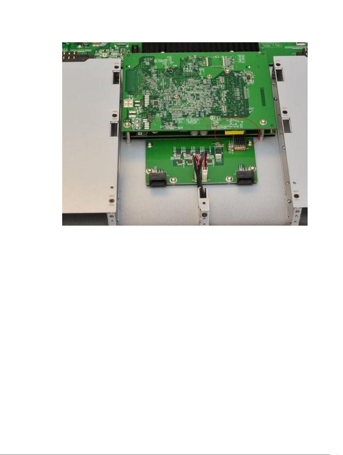
Figure 16. Battery Location
Specifications
55

Figure 17. Close-Up View of the Battery
Batteries or packaging for batteries are labeled in accordance with European Directive 2006/66/EC
concerning batteries and accumulators and waste batteries and accumulators. The Directive determines
the framework for the return and recycling of used batteries and accumulators as applicable throughout
the European Union. This label is applied to various batteries to indicate that the battery is not to be
thrown away, but rather reclaimed upon end of life per this Directive.
In accordance with the European Directive 2006/66/EC, batteries and accumulators are labeled to
indicate that they are to be collected separately and recycled at end of life. The label on the battery may
also include a chemical symbol for the metal concerned in the battery (Pb for lead, Hg for mercury and
Cd for cadmium). Users of batteries and accumulators must not dispose of batteries and accumulators as
unsorted municipal waste, but use the collection framework available to customers for the return,
recycling and treatment of batteries and accumulators.
Customer participation is important to minimize any potential effects of batteries and accumulators on
the environment and human health due to the potential presence of hazardous substances. For proper
collection and treatment, contact your local Dell Networking representative.
56
Specifications

Figure 18. The European WEEE Symbol
For California:
• Perchlorate Material — Special handling may apply.
• Refer to http://www.dtsc.ca.gov/hazardouswaste/perchlorate
The foregoing notice is provided in accordance with California Code of Regulations Title 22, Division 4.5
Chapter 33. Best Management Practices for Perchlorate Materials.
Specifications
57

10
Technical Support
This chapter contains the following sections:
• The iSupport Website
• Contacting the Technical Assistance Center
• Requesting a Hardware Replacement
The iSupport Website
iSupport provides a range of documents and tools to assist you with effectively using Dell Networking
equipment and mitigating the impact of network outages.
Through iSupport you can obtain technical information regarding Dell Networking products, access to
software upgrades and patches, and open and manage your Technical Assistance Center (TAC) cases.
Dell Networking iSupport provides integrated, secure access to these services.
Accessing iSupport Services
The URL for iSupport is http://www.dell.com/support. You must have a userid and password to access
iSupport services. If you do not have a userid and password, you can request these at the website.
To request a userid, password, and iSupport services, follow these steps.
1. On the Dell Networking Support page, click the Account Request link.
2. Fill out the User Account Request form and click Send. You will receive your userid and password by
email.
3. To access iSupport services, click the LOGIN link and enter your userid and password.
Contacting the Technical Assistance Center
How to
Contact Dell
Networking
TAC
Information to
Submit When
Opening a
Support Case
58
Log in to iSupport at http://www.dell.com/support and select the Service Request
tab.
• Your name, company name, phone number, and email address
• Preferred method of contact
• Model number
• Software version number
• Symptom description
Technical Support

Managing Your
Case
Log in to iSupport and select the Service Request tab to view all open cases and
Return Materials Authorizations (RMAs).
Technical
Documentation
Contact
Information
Log in to iSupport and select the Documents tab. You can access this page without
logging in using the Documentation link on the iSupport page.
Web: http://www.dell.com.
Telephone:
• US and Canada: 1.866.965.5800
• International: +1.800.456.3355
Requesting a Hardware Replacement
To request replacement hardware, follow these steps.
1. Determine the part number and serial number of the component.
2. Request an RMA number from TAC by opening a support case. Open a support case by:
• Using the Create Service Request form on the iSupport page (refer to Contacting the Technical
Assistance Center).
• Contacting Dell Networking directly by email or by phone (refer to Contacting the Technical
Assistance Center). Provide the following information when using email or phone:
– Part number, description, and serial number of the component.
– Your name, organization name, telephone number, fax number, and email address.
– Shipping address for the replacement component, including a contact name, phone number,
and email address.
– A description of the failure, including log messages.
Technical Support
59
 Loading...