

Dell S3100 Series Getting Started Manual

Dell Networking S3100 Series
Getting Started Guide
Regulatory Model: S3100

Notes, cautions, and warnings
NOTE: A NOTE indicates important information that helps you make better
use of your computer.
CAUTION: A CAUTION indicates either potential damage to hardware or loss
of data and tells you how to avoid the problem.
WARNING: A WARNING indicates a potential for property damage, personal
injury, or death.
Copyright © 2016 Dell Inc. All rights reserved. This product is protected by U.S. and
international copyright and intellectual property laws. Dell™ and the Dell logo are trademarks
of Dell Inc. in the United States and/or other jurisdictions. All other marks and names
mentioned herein may be trademarks of their respective companies.
2016 - 04
Rev. A01

1
About this Guide
This document is intended as a Getting Started Guide to get new systems up
and running and ready for configuration.
For more details about S3100 series installation and software configuration,
see the following information, available on the Dell Networking Support
website (http://www.dell.com/support).
• The Dell Networking S3100 Series Installation Guide describes installation
and replacement procedures.
• The Dell Configuration Guide for the S3100 Series describes software
configuration.
• The Dell Command Line Reference Guide for the S3100 Series provides
command line interface (CLI) information.
• The Dell Networking S3100 Series Release Notes provide information
about upgrading the S3100 series.
About this Guide
3

2
Installation
This information describes installation of a S3100 series system. Dell
Networking recommends completing the installation procedures in the order
presented here.
Operation and Safety Considerations
Before installing the switch, review these operation and safety guidelines.
Review these guidelines for switch installation:
• You have enough clearance to the front of the switch so you can read the
light emitting diodes (LEDs).
• The AC power cord reaches from the power outlet to the power supply
unit (PSU) side connector.
• The switch is rack-mounted before you power it up.
• Cabling is away from sources of electrical noise, such as radios, power
lines, and fluorescent lighting. Ensure that the cabling is safely away from
other devices that might damage the cables. If needed, allow one rack unit
(RU) space between devices to provide room for cabling.
• Airflow around the switch and through the vents is unrestricted.
• Temperature around the unit does not exceed 113°F (45°C). If the switch is
in a closed or multi-rack assembly, the temperature might be higher than
normal room temperature.
• Humidity around the switch does not exceed 95 percent.
• Altitude at the installation site is below 10,000 feet.
• The switch is installed in an environment as free as possible from dust and
foreign conductive material (such as metal flakes from construction
activities). Cooling mechanisms, such as fans and blowers in the switch,
can draw dust and other particles causing contaminant buildup inside the
chassis, which can result in system malfunction.
Review these guidelines for rack mounting:
• Rack mounting — You may either place the switch on a rack shelf or
mount the switch directly into a 19" wide, EIA-310-E- compliant rack.
4
Installation
• Rack loading — Overloading or uneven loading of racks may result in shelf
or rack failure, causing damage to the equipment and possible personal
injury. Stabilize racks in a permanent location before loading begins.
Mount the components starting at the bottom of the rack, then work to
the top. Do not exceed your rack load rating.
• Power considerations — Connect only to the power source specified on
the unit. When you install multiple electrical components in a rack, ensure
that the total component power ratings do not exceed the circuit
capabilities. Overloaded power sources and extension cords present fire
and shock hazards.
• Elevated ambient temperature — If you install the equipment in a closed
rack assembly, the operating temperature of the rack environment may be
greater than the room ambient temperature. The acceptable ambient
temperature ranges are listed in the S3100 Series Technical Specifications
section under Environmental Parameters.
• Reduced air flow — Install the equipment in the rack so that you do not
compromise the amount of airflow required for safe operation of the
switch. For proper ventilation, position the chassis in an equipment rack
(or cabinet) with a minimum of 5 inches (12.7 cm) of clearance around
exhaust vents.
• Reverse air flow — To ensure cool air intake and to avoid hot air blow out
from the I/O side, ensure that you have the necessary clearance.
• Reliable earthing — Maintain reliable earthing of rack-mounted
equipment. Pay particular attention to the supply connections other than
the direct connections to the branch circuit; for example, use of power
strips.
• Do not mount the equipment with the PSU side facing in a downward
position.
NOTE: Always handle the system and its components with care. Avoid
dropping the chassis or their field replaceable units.
CAUTION: Always wear an electrostatic discharge (ESD)-preventive
wrist or heel ground strap when handling a system and its
components. As with all electrical devices of this type, take all
necessary safety precautions to prevent injury when installing this
system. ESD damage can occur if components are mishandled.
CAUTION: Only trained and qualified personnel should install this
equipment. Read this guide before installing and powering up the
system.
WARNING: This is a condensed reference. Read the safety instructions
in your Safety, Environmental, and Regulatory information booklet
before you begin.
Installation
5

Unpacking a S3100 Series Switch
To unpack your switch, follow these steps.
NOTE: Before unpacking the switch, inspect the container and
immediately report any evidence of damage.
When unpacking each S3100 series switch, make sure that the following
items are included:
• One S3100 series switch.
• One RJ-45 to DB-9 female cable.
• One Dell ReadyRails™ kit for rack installation, two mounting brackets,
bolts, and cage nuts.
• One set of self-adhesive rubber pads for free-standing installation (four
pads are included).
• One PSU.
• Getting Started Guide.
• Safety and Regulatory Information.
• Warranty and Support Information.
• Software License Agreement.
1. Place the container on a clean, flat surface and cut all straps securing the
container.
2. Open the container or remove the container top.
3. Carefully remove the switch from the container and place it on a secure
and clean surface.
4. Remove all packing material.
5. Inspect the product and accessories for damage.
Installing the Dell ReadyRails System
The ReadyRails rack mounting system is provided to easily configure your
rack so that you can install your switch.
The Dell ReadyRails™ system is provided for 1U front-rack and two-post
installations. The ReadyRails system includes two separately packaged rail
assemblies and two rails that are shipped attached to the sides of the switch.
Install the ReadyRails system using the 1U tool-less method or one of three
possible 1U tooled methods (two-post flush mount, two-post center mount,
or four-post threaded).
6
Installation
CAUTION: Do not use the mounted ReadyRails as a shelf or a
workplace.
NOTE: The illustrations in this document are not intended to represent a
specific switch.
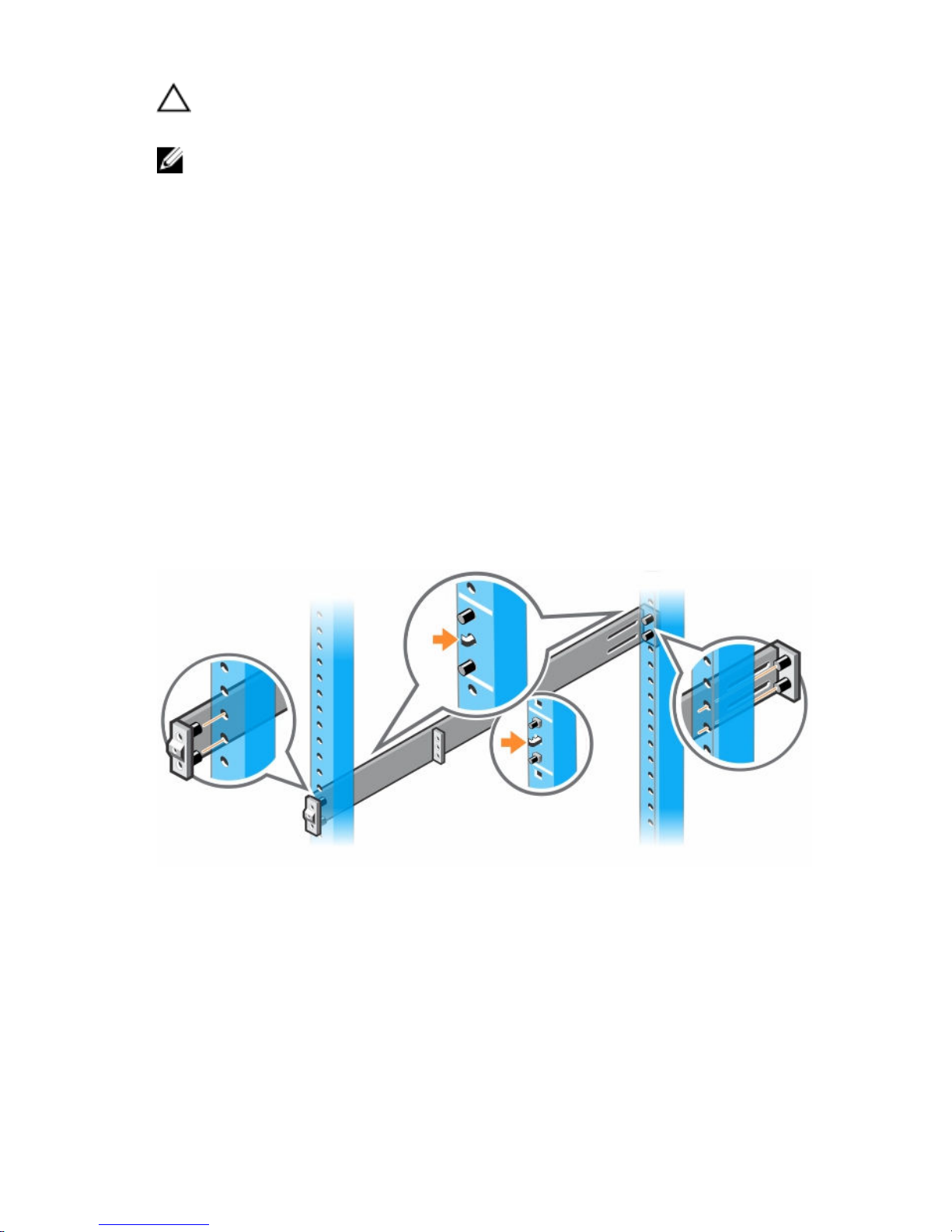
1U Tool-less Configuration
To install the Dell ReadyRails system using the 1U tool-less configuration,
follow these steps.
1. With the ReadyRails flange ears facing outward, place one rail between
the left and right vertical posts. Align and seat the back flange rail pegs in
the back vertical post flange. To see how the pegs appear in both the
square and unthreaded round holes, see item 1 in the following figure.
2. Align and seat the front flange pegs in the holes on the front side of the
vertical post.
3. Repeat this procedure for the second rail.
4. To remove each rail, pull on the latch release button on each flange ear
and unseat each rail.
Figure 1. 1U Tool-less Configuration
Two-Post Flush-Mount Configuration
To install the Dell ReadyRails system using the two-post flush-mount
configuration, follow these steps.
1. For this configuration, remove the castings from the front side of each
ReadyRails assembly. See item 1 in the following figure. Use a Torx driver
to remove the two screws from each front flange ear (on the switch side
Installation
7
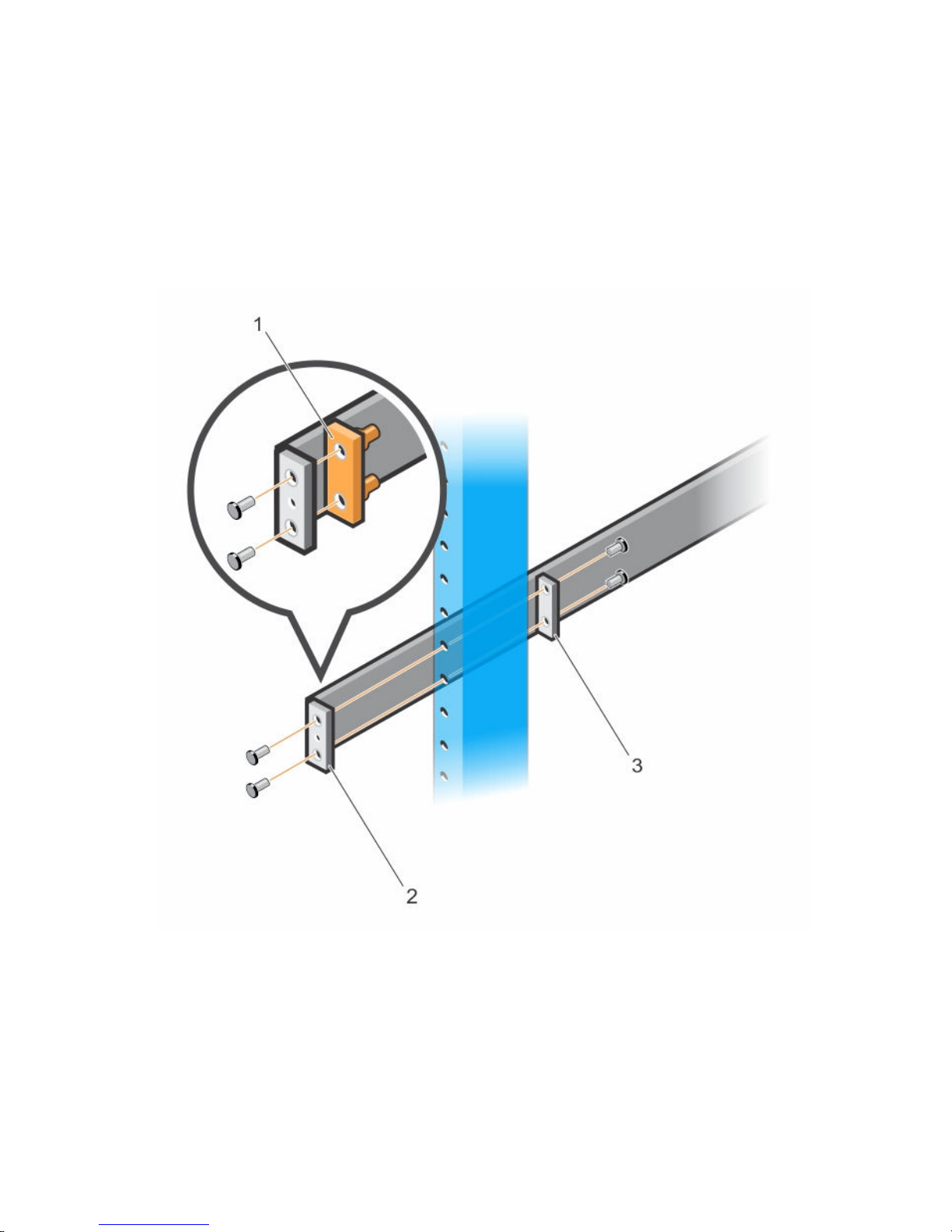
of the rail) and remove each casting. Retain the castings for future rack
requirements. It is not necessary to remove the rear flange castings.
2. Attach one rail to the front post flange with two user-supplied screws.
See item 2 in the following figure.
3. Slide the plunger bracket forward against the vertical post and secure the
plunger bracket to the post flange with two user-supplied screws. See
item 3 in the following figure.
4. Repeat this procedure for the second rail.
Figure 2. Two-Post Flush-Mount Configuration
1. Removing the castings.
2. Attaching rail to the front post flange.
3. Securing the plunger bracket to the post flange.
8
Installation
 Loading...