

Page 1

User’s Guide
Converged Network Adapter
QMD8262-k, QLE8262, QME8262-k
CU0354602-00 L
Third party information brought to
you courtesy of Dell.
Page 2

User’s Guide—Converged Network Adapter
QMD8262-k, QLE8262, QME8262-k
This document is provided for informational purposes only and may contain errors. QLogic reserves the right, without
notice, to make changes to this document or in product design or specifications. QLogic disclaims any warranty of any
kind, expressed or implied, and does not guarantee that any results or performance described in the document will be
achieved by you. All statements regarding QLogic's future direction and intent are subject to change or withdrawal
without notice and represent goals and objectives only.
Document Revision History
Revision A, September 2011
Revision B, March 30, 2012
Revision C, July 18, 2012
Revision D, August 30, 2012
Revision E, November 20, 2012
Revision F, April 8, 2013
Revision G, September 6, 2013
Revision H, June 9, 2014
Revision J, January 22, 2015
Revision K, June 24, 2015
Revision L, March 24, 2016
Changes Sections Affected
Updated disclaimer information. All
Updated QLogic header logos. All
Removed references to QME8242-k All
Added reference to Red Hat Enterprise Linux
“Supported Operating Systems” on page xv
(RHEL) 7.2 and SUSE Linux Enterprise Server 11
SP4
ii CU0354602-00 L
Page 3

Table of Contents
Introduction
Overview . . . . . . . . . . . . . . . . . . . . . . . . . . . . . . . . . . . . . . . . . . . . . . . . . . . xi
Intended Audience . . . . . . . . . . . . . . . . . . . . . . . . . . . . . . . . . . . . . . . . . . . . xi
User’s Guide Content. . . . . . . . . . . . . . . . . . . . . . . . . . . . . . . . . . . . . . . . . . xi
Related Materials . . . . . . . . . . . . . . . . . . . . . . . . . . . . . . . . . . . . . . . . . . . . . xii
Functionality and Features. . . . . . . . . . . . . . . . . . . . . . . . . . . . . . . . . . . . . . xiii
Functional Description. . . . . . . . . . . . . . . . . . . . . . . . . . . . . . . . . . . . . xiii
Features . . . . . . . . . . . . . . . . . . . . . . . . . . . . . . . . . . . . . . . . . . . . . . . xiii
Supported Operating Systems . . . . . . . . . . . . . . . . . . . . . . . . . . . . . . xv
Windows . . . . . . . . . . . . . . . . . . . . . . . . . . . . . . . . . . . . . . . . . . . xv
Linux . . . . . . . . . . . . . . . . . . . . . . . . . . . . . . . . . . . . . . . . . . . . . . xv
VMware . . . . . . . . . . . . . . . . . . . . . . . . . . . . . . . . . . . . . . . . . . . xv
1 Hardware Installation
Overview . . . . . . . . . . . . . . . . . . . . . . . . . . . . . . . . . . . . . . . . . . . . . . . . . . . 1
Hardware and Software Requirements . . . . . . . . . . . . . . . . . . . . . . . . . . . . 1
Safety Precautions . . . . . . . . . . . . . . . . . . . . . . . . . . . . . . . . . . . . . . . . . . . . 1
Pre-Installation Checklist . . . . . . . . . . . . . . . . . . . . . . . . . . . . . . . . . . . . . . . 2
Installing the Adapter . . . . . . . . . . . . . . . . . . . . . . . . . . . . . . . . . . . . . . . . . . 2
Connecting to the Network. . . . . . . . . . . . . . . . . . . . . . . . . . . . . . . . . . . . . . 3
2 Driver Installation and Configuration
Overview . . . . . . . . . . . . . . . . . . . . . . . . . . . . . . . . . . . . . . . . . . . . . . . . . . . 4
Windows Driver Installation and Configuration. . . . . . . . . . . . . . . . . . . . . . . 5
Running the DUP in the GUI . . . . . . . . . . . . . . . . . . . . . . . . . . . . . . . . 5
Running the DUP from the Command Line. . . . . . . . . . . . . . . . . . . . . 12
Options . . . . . . . . . . . . . . . . . . . . . . . . . . . . . . . . . . . . . . . . . . . . 13
Examples . . . . . . . . . . . . . . . . . . . . . . . . . . . . . . . . . . . . . . . . . . 14
Linux Driver Installation and Configuration. . . . . . . . . . . . . . . . . . . . . . . . . . 15
Installation Overview . . . . . . . . . . . . . . . . . . . . . . . . . . . . . . . . . . . . . . 15
Installing the Linux NIC Driver. . . . . . . . . . . . . . . . . . . . . . . . . . . . . . . 15
iii CU0354602-00 L
Page 4

User’s Guide—Converged Network Adapter
QMD8262-k, QLE8262, QME8262-k
Installing the Linux iSCSI Driver . . . . . . . . . . . . . . . . . . . . . . . . . . . . . 16
Building the iSCSI Adapter Driver SLES 11 SP4 . . . . . . . . . . . . 16
Building the iSCSI Adapter Driver for RHEL 6.5
and SLES 12 . . . . . . . . . . . . . . . . . . . . . . . . . . . . . . . . . . . . . . . 18
Building the iSCSI Adapter Driver for RHEL 6.5
and SLES 11 SP3. . . . . . . . . . . . . . . . . . . . . . . . . . . . . . . . . . . . 20
Installing the Linux FCoE Driver . . . . . . . . . . . . . . . . . . . . . . . . . . . . . 23
Building the Driver for RHEL 6.5 Linux. . . . . . . . . . . . . . . . . . . . 23
Building the Driver for SLES 11 SP4 Linux. . . . . . . . . . . . . . . . . 24
Building the Driver for SLES 12 Linux . . . . . . . . . . . . . . . . . . . . 25
Building the Driver for SLES 11 SP3 Linux. . . . . . . . . . . . . . . . . 26
VMware Driver Installation and Configuration . . . . . . . . . . . . . . . . . . . . . . . 28
Installation Overview . . . . . . . . . . . . . . . . . . . . . . . . . . . . . . . . . . . . . . 28
Installing the ESXi 5.x NIC Driver . . . . . . . . . . . . . . . . . . . . . . . . . . . . 28
Updating an Existing Driver or Installing a New Driver for
an Existing ESXi Installation with esxcli (ESXi 5.x Only) . . . . . . 29
Verifying the Version of the Installed Driver (ESXi 5.x Only) . . . 29
Installing the ESXi 5.x iSCSI Driver. . . . . . . . . . . . . . . . . . . . . . . . . . . 30
Updating an Existing Driver or Installing a New Driver for
an Existing ESXi Installation with esxcli (ESXi 5.x Only) . . . . . . 30
Verifying the Version of the Installed Driver (ESXi 5.x Only) . . . 31
Installing the ESXi 5.x FCoE Driver. . . . . . . . . . . . . . . . . . . . . . . . . . . 32
Updating an Existing Driver or Installing a New Driver for
an Existing ESXi Installation with esxcli (ESXi 5.x Only) . . . . . . 32
Verifying the Version of the Installed Driver (ESXi 5.x Only) . . . 33
Installing the ESXi 6.x Fibre Channel Over Ethernet Driver . . . . . . . . 34
Updating an Existing Driver or Installing a New Driver for
an Existing ESXi Installation with esxcli (for ESXi 6x Only) . . . . 34
Installing the ESXi 6.x iSCSI Driver. . . . . . . . . . . . . . . . . . . . . . . . . . . 35
Updating an Existing Driver or Installing a New Driver for
an Existing ESXi Installation with esxcli (for ESXi 6x Only) . . . . 35
iv CU0354602-00 L
Page 5

User’s Guide—Converged Network Adapter
QMD8262-k, QLE8262, QME8262-k
Installing the QConvergeConsole VMware vCenter
Server Plug-in . . . . . . . . . . . . . . . . . . . . . . . . . . . . . . . . . . . . . . . . . . 36
Installation Package Contents . . . . . . . . . . . . . . . . . . . . . . . . . . 36
QConvergeConsole VMware vCenter Server
Plug-in Installation . . . . . . . . . . . . . . . . . . . . . . . . . . . . . . . . . . . 37
Plug-in Unregistration from a Manual Install. . . . . . . . . . . . . . . . 41
Enabling and Disabling the Plug-in. . . . . . . . . . . . . . . . . . . . . . . 42
Uninstalling the QConvergeConsole VMware vCenter
Server Plug-in. . . . . . . . . . . . . . . . . . . . . . . . . . . . . . . . . . . . . . . 44
Installing the QLogic Adapter CIM Provider . . . . . . . . . . . . . . . . 44
Uninstalling the QLogic Adapter CIM Provider . . . . . . . . . . . . . . 47
Installing the vSphere Web Client Plug-in . . . . . . . . . . . . . . . . . . . . . . 48
Uninstalling the vSphere Web Client Plug-in . . . . . . . . . . . . . . . 49
3 Adapter Management Applications
Overview . . . . . . . . . . . . . . . . . . . . . . . . . . . . . . . . . . . . . . . . . . . . . . . . . . . 50
General Management with QConvergeConsole. . . . . . . . . . . . . . . . . . . . . . 51
Configuring the NIC Driver with QConvergeConsole . . . . . . . . . . . . . 51
Configuring iSCSI with QConvergeConsole . . . . . . . . . . . . . . . . . . . . 51
Configuring FCoE with QConvergeConsole . . . . . . . . . . . . . . . . . . . . 51
Configuring iSCSI Offload with QConvergeConsole . . . . . . . . . . . . . . 52
Adapter-Level iSCSI Parameters . . . . . . . . . . . . . . . . . . . . . . . . . . . . 52
Displaying Adapter-Level iSCSI Parameters . . . . . . . . . . . . . . . 52
Modifying Adapter-Level iSCSI Parameters . . . . . . . . . . . . . . . . 53
Port-Level iSCSI Parameters . . . . . . . . . . . . . . . . . . . . . . . . . . . . . . . 53
Displaying Port-Level iSCSI Parameters . . . . . . . . . . . . . . . . . . 53
Modifying Port-Level iSCSI Parameters . . . . . . . . . . . . . . . . . . . 57
Summary of Target Sessions . . . . . . . . . . . . . . . . . . . . . . . . . . . 59
Target Session-Level iSCSI Negotiated Parameters . . . . . . . . . 60
Target Session-Level Persistent iSCSI Parameters . . . . . . . . . . 61
Configuring iSCSI Initiators with QConvergeConsole . . . . . . . . . . . . . 65
Configuring the Windows iSCSI Initiator. . . . . . . . . . . . . . . . . . . 65
Configuring the Linux iSCSI Initiator. . . . . . . . . . . . . . . . . . . . . . 66
Configuring the ESX iSCSI Initiator . . . . . . . . . . . . . . . . . . . . . . 67
Enabling CHAP Authentication with QConvergeConsole . . . . . . . . . . 68
Configuring CHAP with QConvergeConsole CLI . . . . . . . . . . . . 69
Linking to a CHAP Target . . . . . . . . . . . . . . . . . . . . . . . . . . . . . . 71
Windows Management Applications . . . . . . . . . . . . . . . . . . . . . . . . . . . . . . 73
v CU0354602-00 L
Page 6

User’s Guide—Converged Network Adapter
QMD8262-k, QLE8262, QME8262-k
Windows NIC Driver Management Applications . . . . . . . . . . . . . . . . . 73
Overview. . . . . . . . . . . . . . . . . . . . . . . . . . . . . . . . . . . . . . . . . . . 73
Viewing and Changing Adapter Properties. . . . . . . . . . . . . . . . . 73
Windows Teaming . . . . . . . . . . . . . . . . . . . . . . . . . . . . . . . . . . . . . . . . 75
Overview. . . . . . . . . . . . . . . . . . . . . . . . . . . . . . . . . . . . . . . . . . . 75
Teaming Modes . . . . . . . . . . . . . . . . . . . . . . . . . . . . . . . . . . . . . 76
Using the CLI for Teaming . . . . . . . . . . . . . . . . . . . . . . . . . . . . . 79
Using the Team Management GUI . . . . . . . . . . . . . . . . . . . . . . . 80
Teaming Configuration . . . . . . . . . . . . . . . . . . . . . . . . . . . . . . . . 81
Viewing Teaming Statistics . . . . . . . . . . . . . . . . . . . . . . . . . . . . . 91
Windows VLAN Configuration . . . . . . . . . . . . . . . . . . . . . . . . . . . . . . . 92
VLAN Properties. . . . . . . . . . . . . . . . . . . . . . . . . . . . . . . . . . . . . 92
Using the CLI for VLANs . . . . . . . . . . . . . . . . . . . . . . . . . . . . . . 92
Using the GUI for VLANs . . . . . . . . . . . . . . . . . . . . . . . . . . . . . . 93
User Diagnostics for Windows NIC Driver
Management Applications . . . . . . . . . . . . . . . . . . . . . . . . . . . . . . . . . . 96
Running Windows User Diagnostics. . . . . . . . . . . . . . . . . . . . . . 96
Windows Diagnostic Test Descriptions . . . . . . . . . . . . . . . . . . . . 101
Windows Diagnostic Test Messages . . . . . . . . . . . . . . . . . . . . . 103
Linux Management Applications . . . . . . . . . . . . . . . . . . . . . . . . . . . . . . . . . 106
Linux NIC Driver Management Applications . . . . . . . . . . . . . . . . . . . . 106
Overview. . . . . . . . . . . . . . . . . . . . . . . . . . . . . . . . . . . . . . . . . . . 106
Viewing and Changing Adapter Properties on Linux . . . . . . . . . 106
User Diagnostics for Linux NIC Driver Management Applications . . . 108
Running Linux User Diagnostics . . . . . . . . . . . . . . . . . . . . . . . . 109
Linux Diagnostic Test Descriptions . . . . . . . . . . . . . . . . . . . . . . . 111
Linux Diagnostic Test Messages . . . . . . . . . . . . . . . . . . . . . . . . 111
VMware Management Applications . . . . . . . . . . . . . . . . . . . . . . . . . . . . . . . 111
VMware NIC Driver Management Applications . . . . . . . . . . . . . . . . . . 111
Overview. . . . . . . . . . . . . . . . . . . . . . . . . . . . . . . . . . . . . . . . . . . 111
Using Switch Independent Partitioning Under ESX . . . . . . . . . . 112
User Diagnostics for VMware NIC Driver Management
Applications . . . . . . . . . . . . . . . . . . . . . . . . . . . . . . . . . . . . . . . . . . . . . 112
Ethtool . . . . . . . . . . . . . . . . . . . . . . . . . . . . . . . . . . . . . . . . . . . . 112
Unified Extensible Firmware Interface . . . . . . . . . . . . . . . . . . . . . . . . . . . . . 113
UEFI Package Contents . . . . . . . . . . . . . . . . . . . . . . . . . . . . . . . . . . . 11 3
Supported Features. . . . . . . . . . . . . . . . . . . . . . . . . . . . . . . . . . . . . . . 114
Fibre Channel Adapter Configuration . . . . . . . . . . . . . . . . . . . . . . . . . 114
Updating the UEFI (EfiUtilx64) . . . . . . . . . . . . . . . . . . . . . . . . . . . . . . 114
vi CU0354602-00 L
Page 7

User’s Guide—Converged Network Adapter
QMD8262-k, QLE8262, QME8262-k
Configuring iSCSI over DCBX . . . . . . . . . . . . . . . . . . . . . . . . . . . . . . . . . . . 115
Configuring the iSCSI VLAN on the QLogic Adapter. . . . . . . . . . . . . . 116
Configuring the Switch for iSCSI over DCBX . . . . . . . . . . . . . . . . . . . 117
Verify the Version of the Switch Firmware . . . . . . . . . . . . . . . . . 117
Create and Configure the iSCSI VLAN on the Switch . . . . . . . . 117
Create and Configure the CEE Map for iSCSI Traffic
Bandwidth and PFC . . . . . . . . . . . . . . . . . . . . . . . . . . . . . . . . . . 117
Configure LLDP/DCBX for the iSCSI TLV . . . . . . . . . . . . . . . . . 118
Configure the CEE Port’s iSCSI Traffic Class. . . . . . . . . . . . . . . 119
Verifying Adapter/Switch Status for iSCSI Login, Traffic,
and PFC . . . . . . . . . . . . . . . . . . . . . . . . . . . . . . . . . . . . . . . . . . . 119
Interoperation of Bandwidth Settings for DCBX and
Switch Independent Partitioning . . . . . . . . . . . . . . . . . . . . . . . . . . . . . 121
Choosing DCBX or Switch Independent Partitioning. . . . . . . . . . . . . . 121
4 Switch Independent Partitioning
Overview . . . . . . . . . . . . . . . . . . . . . . . . . . . . . . . . . . . . . . . . . . . . . . . . . . . 123
Switch Independent Partitioning Setup Requirements. . . . . . . . . . . . . . . . . 124
Hardware Requirements . . . . . . . . . . . . . . . . . . . . . . . . . . . . . . . . . . . 124
Software Requirements. . . . . . . . . . . . . . . . . . . . . . . . . . . . . . . . . . . . 124
Switch Independent Partitioning Configuration . . . . . . . . . . . . . . . . . . . . . . 126
What Is Switch Independent Partitioning?. . . . . . . . . . . . . . . . . . . . . . 126
Switch Independent Partitioning Options. . . . . . . . . . . . . . . . . . . . . . . 127
Personality Changes . . . . . . . . . . . . . . . . . . . . . . . . . . . . . . . . . . . . . . 130
Quality of Service . . . . . . . . . . . . . . . . . . . . . . . . . . . . . . . . . . . . . . . . 131
eSwitch . . . . . . . . . . . . . . . . . . . . . . . . . . . . . . . . . . . . . . . . . . . . . . . . 132
Configuration Management Tools . . . . . . . . . . . . . . . . . . . . . . . . . . . . 133
Dell System Setup . . . . . . . . . . . . . . . . . . . . . . . . . . . . . . . . . . . 133
QLogic OptionROM at POST . . . . . . . . . . . . . . . . . . . . . . . . . . . 133
QConvergeConsole GUI. . . . . . . . . . . . . . . . . . . . . . . . . . . . . . . 134
QConvergeConsole CLI . . . . . . . . . . . . . . . . . . . . . . . . . . . . . . . 135
Windows Device Manager . . . . . . . . . . . . . . . . . . . . . . . . . . . . . 135
CIM Provider and QConvergeConsole VMware vCenter
Server Plug-in for VMware ESX/ESXi . . . . . . . . . . . . . . . . . . . . 135
Switch Independent Partitioning Setup and Management Options . . . . . . . 137
Overview . . . . . . . . . . . . . . . . . . . . . . . . . . . . . . . . . . . . . . . . . . . . . . . 137
Dell System Setup. . . . . . . . . . . . . . . . . . . . . . . . . . . . . . . . . . . . . . . . 138
QLogic OptionROM at POST . . . . . . . . . . . . . . . . . . . . . . . . . . . . . . . 145
vii CU0354602-00 L
Page 8

User’s Guide—Converged Network Adapter
QMD8262-k, QLE8262, QME8262-k
QConvergeConsole GUI . . . . . . . . . . . . . . . . . . . . . . . . . . . . . . . . . . . 149
Configure NIC Partitions. . . . . . . . . . . . . . . . . . . . . . . . . . . . . . . 149
Set Up QoS . . . . . . . . . . . . . . . . . . . . . . . . . . . . . . . . . . . . . . . . 151
View eSwitch Configuration . . . . . . . . . . . . . . . . . . . . . . . . . . . . 153
QConvergeConsole CLI . . . . . . . . . . . . . . . . . . . . . . . . . . . . . . . . . . . 154
Windows Device Manager. . . . . . . . . . . . . . . . . . . . . . . . . . . . . . . . . . 159
Configure Switch Independent Partitioning . . . . . . . . . . . . . . . . 160
Change Personalities . . . . . . . . . . . . . . . . . . . . . . . . . . . . . . . . . 162
Manage Bandwidth. . . . . . . . . . . . . . . . . . . . . . . . . . . . . . . . . . . 164
View eSwitch Statistics . . . . . . . . . . . . . . . . . . . . . . . . . . . . . . . . 167
CIM Provider and vCenter Server Plug-in for VMware ESX/ESXi. . . . 168
Switch Independent Partitioning Setup . . . . . . . . . . . . . . . . . . . . . . . . . . . . 172
Default Settings . . . . . . . . . . . . . . . . . . . . . . . . . . . . . . . . . . . . . . . . . . 172
Configuration Options . . . . . . . . . . . . . . . . . . . . . . . . . . . . . . . . . . . . . 173
Switch Independent Partitioning Configuration Parameters and
Setup Tools . . . . . . . . . . . . . . . . . . . . . . . . . . . . . . . . . . . . . . . . . . . . . 174
5 Boot Configuration
Overview . . . . . . . . . . . . . . . . . . . . . . . . . . . . . . . . . . . . . . . . . . . . . . . . . . . 176
Boot from SAN . . . . . . . . . . . . . . . . . . . . . . . . . . . . . . . . . . . . . . . . . . . . . . . 177
General Boot from SAN. . . . . . . . . . . . . . . . . . . . . . . . . . . . . . . . . . . . 177
Windows Boot from SAN. . . . . . . . . . . . . . . . . . . . . . . . . . . . . . . . . . . 177
Creating a Driver Disk . . . . . . . . . . . . . . . . . . . . . . . . . . . . . . . . 177
Windows 2008 Boot From SAN . . . . . . . . . . . . . . . . . . . . . . . . . 178
Linux Boot from SAN. . . . . . . . . . . . . . . . . . . . . . . . . . . . . . . . . . . . . . 178
Red Hat Enterprise Linux Boot from SAN . . . . . . . . . . . . . . . . . 178
SUSE Linux Enterprise Server (Novell) Boot from SAN. . . . . . . 179
ESX Boot from SAN . . . . . . . . . . . . . . . . . . . . . . . . . . . . . . . . . . . . . . 180
Dell System Setup . . . . . . . . . . . . . . . . . . . . . . . . . . . . . . . . . . . . . . . . . . . . 181
Accessing Dell System Setup . . . . . . . . . . . . . . . . . . . . . . . . . . . . . . . 182
Main Configuration . . . . . . . . . . . . . . . . . . . . . . . . . . . . . . . . . . . . . . . 184
Device and Firmware Image Information . . . . . . . . . . . . . . . . . . 184
NIC Configuration . . . . . . . . . . . . . . . . . . . . . . . . . . . . . . . . . . . . 185
iSCSI Configuration . . . . . . . . . . . . . . . . . . . . . . . . . . . . . . . . . . 186
FCoE Configuration . . . . . . . . . . . . . . . . . . . . . . . . . . . . . . . . . . 192
NIC Partitioning (Switch Independent Partitioning)
Configuration . . . . . . . . . . . . . . . . . . . . . . . . . . . . . . . . . . . . . . . 193
PXE Boot Setup . . . . . . . . . . . . . . . . . . . . . . . . . . . . . . . . . . . . . . . . . . . . . . 199
Configuring PXE Boot . . . . . . . . . . . . . . . . . . . . . . . . . . . . . . . . . . . . . 199
iSCSI Configuration Using Fast!UTIL. . . . . . . . . . . . . . . . . . . . . . . . . . . . . . 201
viii CU0354602-00 L
Page 9

User’s Guide—Converged Network Adapter
QMD8262-k, QLE8262, QME8262-k
Accessing Fast!UTIL . . . . . . . . . . . . . . . . . . . . . . . . . . . . . . . . . . . . . . 201
Configuring Host Adapter Settings . . . . . . . . . . . . . . . . . . . . . . . . . . . 201
Configuring iSCSI Boot Settings . . . . . . . . . . . . . . . . . . . . . . . . . . . . . 202
Boot Device Primary and Alternate . . . . . . . . . . . . . . . . . . . . . . 203
Adapter Boot Mode. . . . . . . . . . . . . . . . . . . . . . . . . . . . . . . . . . . 203
Primary and Alternate Boot Device Settings . . . . . . . . . . . . . . . 204
Configuring the iSCSI Boot Parameters . . . . . . . . . . . . . . . . . . . 204
Configuring QLogic iSCSI Boot . . . . . . . . . . . . . . . . . . . . . . . . . 207
Booting . . . . . . . . . . . . . . . . . . . . . . . . . . . . . . . . . . . . . . . . . . . . 213
iBFT Boot Setup. . . . . . . . . . . . . . . . . . . . . . . . . . . . . . . . . . . . . . . . . . . . . . 214
Enabling iBFT Boot . . . . . . . . . . . . . . . . . . . . . . . . . . . . . . . . . . . . . . . 214
Booting to a Target Disk . . . . . . . . . . . . . . . . . . . . . . . . . . . . . . . . . . . 216
DHCP Boot Setup (iSCSI) . . . . . . . . . . . . . . . . . . . . . . . . . . . . . . . . . . . . . . 219
Configuring DHCP iSCSI Boot for IPv4. . . . . . . . . . . . . . . . . . . . . . . . 219
DHCP Option 17, Root Path. . . . . . . . . . . . . . . . . . . . . . . . . . . . 220
DHCP Option 43 (Adding Vendor Options) . . . . . . . . . . . . . . . . 220
A Troubleshooting
Diagnosing Problems . . . . . . . . . . . . . . . . . . . . . . . . . . . . . . . . . . . . . . . . . . 222
NIC Troubleshooting . . . . . . . . . . . . . . . . . . . . . . . . . . . . . . . . . . . . . . . . . . 223
iSCSI Troubleshooting . . . . . . . . . . . . . . . . . . . . . . . . . . . . . . . . . . . . . . . . . 224
FCoE Troubleshooting . . . . . . . . . . . . . . . . . . . . . . . . . . . . . . . . . . . . . . . . . 225
ESX Troubleshooting . . . . . . . . . . . . . . . . . . . . . . . . . . . . . . . . . . . . . . . . . . 227
B Specifications
QMD8262-k Specifications. . . . . . . . . . . . . . . . . . . . . . . . . . . . . . . . . . . . . . 229
Physical Characteristics . . . . . . . . . . . . . . . . . . . . . . . . . . . . . . . . . . . 229
Power Requirements. . . . . . . . . . . . . . . . . . . . . . . . . . . . . . . . . . . . . . 229
Standards Specifications . . . . . . . . . . . . . . . . . . . . . . . . . . . . . . . . . . . 229
Interface Specifications . . . . . . . . . . . . . . . . . . . . . . . . . . . . . . . . . . . . 230
Environmental Specifications. . . . . . . . . . . . . . . . . . . . . . . . . . . . . . . . 231
QLE8262 Specifications . . . . . . . . . . . . . . . . . . . . . . . . . . . . . . . . . . . . . . . . 232
Physical Characteristics . . . . . . . . . . . . . . . . . . . . . . . . . . . . . . . . . . . 232
Power Requirements. . . . . . . . . . . . . . . . . . . . . . . . . . . . . . . . . . . . . . 232
Standards Specifications . . . . . . . . . . . . . . . . . . . . . . . . . . . . . . . . . . . 232
Interface Specifications . . . . . . . . . . . . . . . . . . . . . . . . . . . . . . . . . . . . 232
Environmental Specifications. . . . . . . . . . . . . . . . . . . . . . . . . . . . . . . . 232
QME8262-k Specifications. . . . . . . . . . . . . . . . . . . . . . . . . . . . . . . . . . . . . . 233
Physical Characteristics . . . . . . . . . . . . . . . . . . . . . . . . . . . . . . . . . . . 233
Power Requirements. . . . . . . . . . . . . . . . . . . . . . . . . . . . . . . . . . . . . . 233
ix CU0354602-00 L
Page 10

User’s Guide—Converged Network Adapter
QMD8262-k, QLE8262, QME8262-k
Standards Specifications . . . . . . . . . . . . . . . . . . . . . . . . . . . . . . . . . . . 233
Interface Specifications . . . . . . . . . . . . . . . . . . . . . . . . . . . . . . . . . . . . 233
Environmental Specifications. . . . . . . . . . . . . . . . . . . . . . . . . . . . . . . . 233
C QConvergeConsole GUI
Introduction to QConvergeConsole . . . . . . . . . . . . . . . . . . . . . . . . . . . . . . . 235
Downloading QConvergeConsole Documentation. . . . . . . . . . . . . . . . . . . . 236
Downloading and Installing Management Agents . . . . . . . . . . . . . . . . . . . . 236
Installing the Agents from the QLogic Web Site . . . . . . . . . . . . . . . . . 237
Installing the Agents Using the Built-in Agent Installer . . . . . . . . . . . . 237
Installing the QConvergeConsole GUI . . . . . . . . . . . . . . . . . . . . . . . . . . . . . 238
Installing QConvergeConsole in a Windows Environment . . . . . . . . . 238
Installing QConvergeConsole in a Linux Environment . . . . . . . . . . . . 239
Installing QConvergeConsole in Silent Mode . . . . . . . . . . . . . . . . . . . 240
What Is in the QConvergeConsole Help System . . . . . . . . . . . . . . . . . . . . . 241
D Regulatory Information
Warranty. . . . . . . . . . . . . . . . . . . . . . . . . . . . . . . . . . . . . . . . . . . . . . . . . . . . 243
Regulatory and Compliance Information . . . . . . . . . . . . . . . . . . . . . . . . . . . 243
Laser Safety . . . . . . . . . . . . . . . . . . . . . . . . . . . . . . . . . . . . . . . . . . . . 243
FDA Notice . . . . . . . . . . . . . . . . . . . . . . . . . . . . . . . . . . . . . . . . . 243
Agency Certification. . . . . . . . . . . . . . . . . . . . . . . . . . . . . . . . . . . . . . . 244
EMI and EMC Requirements . . . . . . . . . . . . . . . . . . . . . . . . . . . 244
KCC: Class A . . . . . . . . . . . . . . . . . . . . . . . . . . . . . . . . . . . . . . . 245
Product Safety Compliance. . . . . . . . . . . . . . . . . . . . . . . . . . . . . . . . . 245
x CU0354602-00 L
Page 11

Introduction
NOTE
Overview
This user’s guide covers the following products:
QLogic QMD8262-k blade network daughter card
QLogic QLE8262 monolithic server standup card
QLogic QME8262-k blade mezzanine card
Throughout this document, the term adapter refers to any or all of these
products.
This guide provides technical information about the adapters, including how to
install and configure the adapter, as well as detailed descriptions of the adapter’s
various uses and functions.
Intended Audience
This guide is intended for system administrators and other technical staff
members responsible for configuring and managing adapters installed on Dell
PowerEdge
®
servers in Windows®, Linux®, or VMware® environments.
User’s Guide Content
The QLogic QMD8262-k/QLE8262/QME8262-k User’s Guide includes the
following sections:
Hardware Installation covers the hardware and software requirements,
safety precautions, a pre-installation checklist, and adapter installation.
Driver Installation and Configuration covers the installation of the three
drivers—NIC, iSCSI, and Fibre Channel over Ethernet (FCoE)—included
with the adapter on Windows, Linux, and VMware operating systems.
Adapter Management Applications covers how to use QConvergeConsole
as well as operating-system-specific applications for Windows, Linux, and
VMware.
®
®
xi CU0354602-00 L
,
Page 12

Introduction
NOTE
Related Materials
Switch Independent Partitioning covers how to configure Switch
Independent Partitioning using utilities such as QConvergeConsole, as well
as configuring iSCSI over data center bridging exchange (DCBX) using a
®
Brocade
Series 8000 FCoE switch and a QLogic iSCSI Host Bus Adapter.
Boot Configuration provides information on booting from SAN, pre-execution
environment (PXE) boot setup, and iSCSI boot configuration using
Fast!UTIL, iSCSI Boot Firmware Table (iBFT), DHCP, and
QConvergeConsole.
Troubleshooting provides troubleshooting flowcharts of steps for diagnosing
adapter problems specific to NIC, iSCSI, FCoE, and ESX
Specifications defines the physical characteristics and power requirements,
and lists supported standards, interface specifications, and environmental
specifications.
QConvergeConsole GUI provides an overview of the QConvergeConsole
Web management interface.
Regulatory Information provides warranty, regulatory, and compliance
information.
Related Materials
For additional information, refer to the following:
QConvergeConsole GUI Help System, available through the
QConvergeConsole GUI, provides help topics on configuring and managing
host servers and adapters using the QConvergeConsole GUI.
QConvergeConsole GUI Installation Guide contains instructions for installing
and starting the QConvergeConsole GUI.
QConvergeConsole CLI User’s Guide provides reference material on using
the QConvergeConsole CLI.
®
.
QLogic QConvergeConsole Plug-ins for vSphere User’s Guide provides
reference material on using the QConvergeConsole VMware vCenter Server
Plug-in and the QConvergeConsole VMware vSphere Web Client Plug-in.
To access QLogic documents online, go to www.qlogic.com and click
Downloads.
xii CU0354602-00 L
Page 13

Introduction
Functionality and Features
Functionality and Features
This section provides the following information:
Functional Description
Features
Supported Operating Systems
Functional Description
Functional descriptions for the adapters are as follows:
QMD8262-k: This a network daughter card with FCoE and iSCSI offload for
the blade server environment.
Features
QLE8262:
for the rack and tower server environment.
QME8262-k: This is a mezzanine card with FCoE and iSCSI offload for the
blade server environment.
The adapters provide the following features:
Switch Independent Partitioning
Message signaled interrupts (MSI-X)
Device management for power and SAN
Multi-boot capability including:
PXE
iSCSI
Fibre Channel
Unified extensible firmware interface (UEFI)
PCIe
User diagnostics that can be run from the CLI and the GUI
Ethernet functions include:
2x10 gigabit Ethernet (GbE) with KR (copper backplane) (does not
Priority and virtual LAN (VLAN) tagging
This is a standard form-factor adapter with FCoE and iSCSI offload
®
2.0 x8
apply to QLE8262)
Jumbo frames up to 9618 bytes
Enhanced Ethernet functions include:
Priority-based flow control
Enhanced transmission selection
Advanced teaming
VLAN configuration and management
Preservation of teaming and VLAN configuration information during
driver upgrade
xiii CU0354602-00 L
Page 14

Introduction
Functionality and Features
Advanced stateless offload features include:
IP, TCP, and user datagram protocol (UDP) checksums
Large segment offload (LSO)
Large receive offload (LRO)
Stateful offload features include:
iSCSI offload
Fibre Channel and FCoE offload
Advanced management features for Converged Network Adapters and Fibre
Channel adapters, including QConvergeConsole (GUI and CLI)
Interrupt management and scalability features including:
Receive side scaling (RSS)
Interrupt moderation
Flow control
Locally administered address (LAA)
Enhanced optimization with MSI, MSI-X, and NetQueue
xiv CU0354602-00 L
Page 15

Introduction
NOTE
Functionality and Features
Supported Operating Systems
The adapter supports the following operating systems. To view the most complete
and current list, refer to the product release notes.
Windows
Windows Server® 2012 R2
Windows Server 2012
Windows Server 2008 R2 SP1
Windows Server 2008 SP2 x64
Windows Server 2008 SP2 x32
Linux
Red Hat® Enterprise Linux (RHEL®) 7.2
Red Hat Enterprise Linux (RHEL) 7.0
Red Hat Enterprise Linux (RHEL) 6.5
SUSE
SUSE Linux Enterprise Server 11 SP3
SUSE Linux Enterprise Server 11 SP4
®
Linux Enterprise Server 12
VMware
vSphere®: VMwareESXi 6.0
vSphere: VMwareESXi 5.5 U2
vSphere: VMwareESXi 5.1 U3
For the most current versions of the OS and drivers supported by the
adapter, refer to the release notes. The release notes are supplied in the
release.txt file.
xv CU0354602-00 L
Page 16

1 Hardware Installation
CAUTION
!
Overview
This section provides the hardware and software requirements, safety
precautions, a pre-installation checklist, and a procedure for installing the adapter.
Hardware and Software Requirements
Before you install the adapter, verify that your system meets the following
hardware and software requirements.
Hardware
For port and slot assignments for the QMD8262-k or QME8262-k
adapter, refer to the blade and M1000e chassis diagram in the Dell
PowerEdge M1000e Systems Configuration Guide.
For QLE8262 adapter port and slot assignments, refer to the
“Expansion Cards” section of the Hardware Owner’s Manual for your
Dell PowerEdge server.
Software: For information on the supported operating systems, firmware
versions, adapter drivers, and utilities, refer to the product release notes.
Safety Precautions
The adapter is being installed in a system that operates with voltages that
can be lethal. Before you open the case of your system, observe the
following precautions to protect yourself and to prevent damage to the
system components.
Remove any metallic objects or jewelry from your hands and wrists.
Make sure to use only insulated or nonconducting tools.
1 CU0354602-00 L
Page 17

1–Hardware Installation
NOTE
Pre-Installation Checklist
Before you touch internal components, verify that the system is powered
OFF and is unplugged.
Install or remove adapters in a static-free environment. The use of a properly
grounded wrist strap or other personal antistatic devices and an antistatic
mat is strongly recommended.
Pre-Installation Checklist
1. Verify that your system meets the hardware and software requirements
listed in “Hardware and Software Requirements” on page 1.
2. Verify that your system is using the latest BIOS.
If you acquired the adapter software on a disk or from the Dell support
Web site (http://support.dell.com
files.
), verify the path to the adapter driver
3. Check the adapter for visible signs of damage. Never attempt to install a
damaged adapter.
Installing the Adapter
Follow the instructions for your adapter.
QMD8262-k, QME8262-k
Refer to the “I/O Module Mezzanine Cards” and “Guidelines for Installing I/O
Modules” sections of the Dell PowerEdge Modular Systems Hardware Owner’s
Manual:
ftp://ftp.dell.com/Manuals/all-products/esuprt_ser_stor_net/esuprt_poweredge/po
weredge-m610x_Owner%27s%20Manual_en-us.pdf
QLE8262
To install the QLE8262 adapter, follow these steps:
1. Power off the computer and all attached devices such as monitors, printers,
and external components.
2. Disconnect the power cable.
3. Remove the computer cover and find an empty PCIe x8 bus slot.
4. Pull out the slot cover (if any).
5. Grasp the adapter by the top edge and seat it firmly into the appropriate slot.
6. Refasten the adapter’s retaining bracket.
2 CU0354602-00 L
Page 18

1–Hardware Installation
Connecting to the Network
7. Close the computer cover.
8. Plug the Ethernet cable into the adapter.
9. Plug in the power cable and turn on the computer.
For more detailed information, refer to the Hardware Owner’s Manual for your Dell
PowerEdge server.
Connecting to the Network
Follow the instructions for your adapter.
QMD8262-k, QME8262-k
Refer to the “Guidelines for Installing I/O Modules” section of the Dell PowerEdge
Modular Systems Hardware Owner’s Manual:
ftp://ftp.dell.com/Manuals/all-products/esuprt_ser_stor_net/esuprt_poweredge/po
weredge-m610x_Owner%27s%20Manual_en-us.pdf
QLE8262
Refer to the Hardware Owner’s Manual for your Dell PowerEdge server.
3 CU0354602-00 L
Page 19

2 Driver Installation and
NOTE
NOTE
Configuration
Overview
If you need to update the Flash memory of multiple adapters simultaneously:
For the QConvergeConsole GUI, refer to the “Update the Flash Using
the Flash Update Wizard” topic in the QConvergeConsole Help System.
For the QConvergeConsole CLI, use the -flashsupport command to
update the Flash memory for all cards supported by the specified file (for
example, qaucli -pr nic -flashsupport -i ALL -a
p3p11179.bin).
This section provides links to the following information about the three
drivers—NIC, iSCSI, and FCoE—included with the adapter:
Windows Driver Installation and Configuration
Linux Driver Installation and Configuration
VMware Driver Installation and Configuration
When you disable the firmware (for example, during a firmware dump or
during a firmware update) in Windows or Linux with a QConvergeConsole
agent, multiple application messages are generated. These messages are
generated because the application cannot communicate with the adapter
while the firmware is disabled. After the firmware is re-enabled, the errors
will go away.
4 CU0354602-00 L
Page 20
2–Driver Installation and Configuration
NOTE
Windows Driver Installation and Configuration
Windows Driver Installation and Configuration
A software or driver Dell update package (DUP) can be run in two ways:
Running the DUP in the GUI
Running the DUP from the Command Line
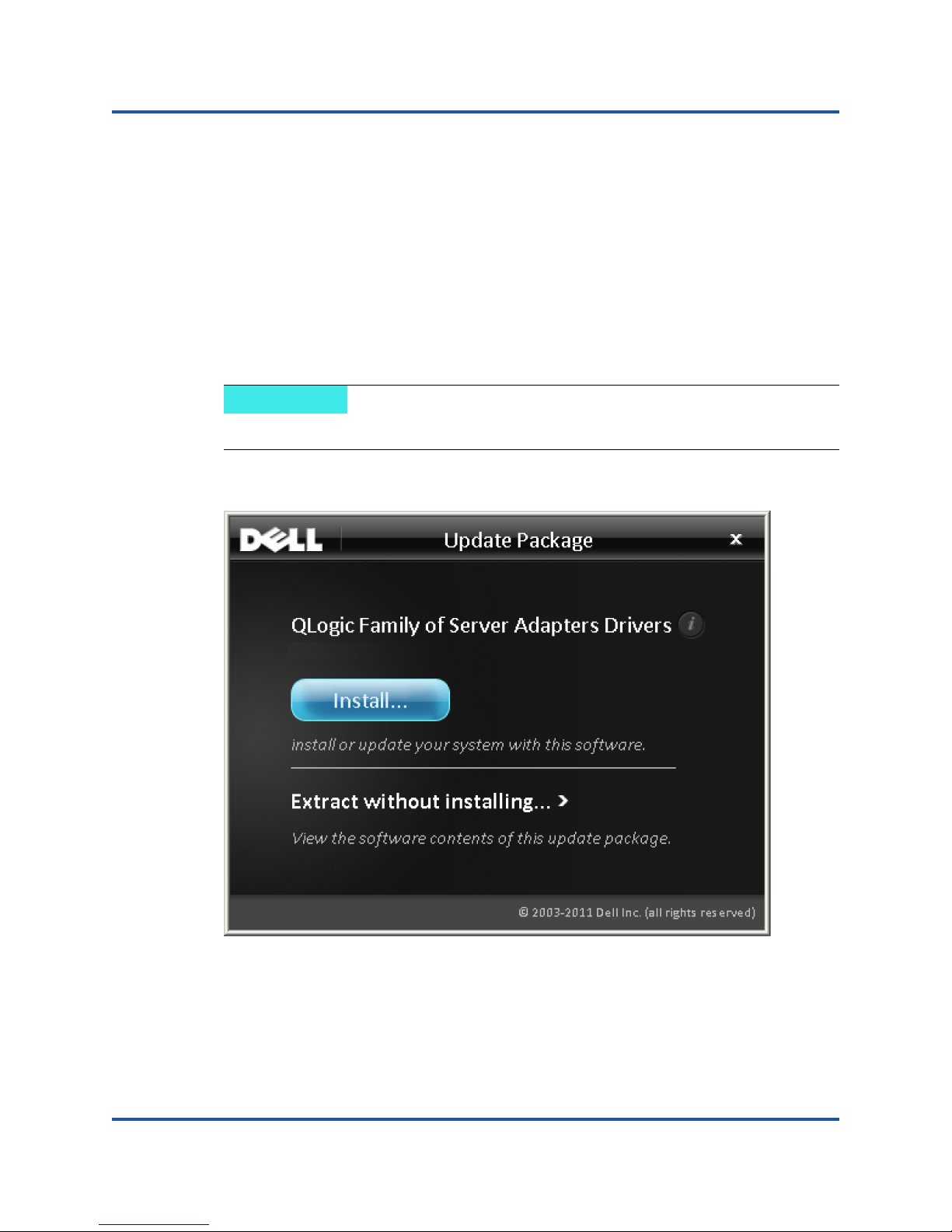
Running the DUP in the GUI
To run the DUP in the GUI:
1. Double-click the icon representing the DUP file.
The actual file name of the DUP varies.
The Update Package window appears, as shown in Figure 2-1.
Figure 2-1. Update Package Window
5 CU0354602-00 L
Page 21
2–Driver Installation and Configuration
Windows Driver Installation and Configuration
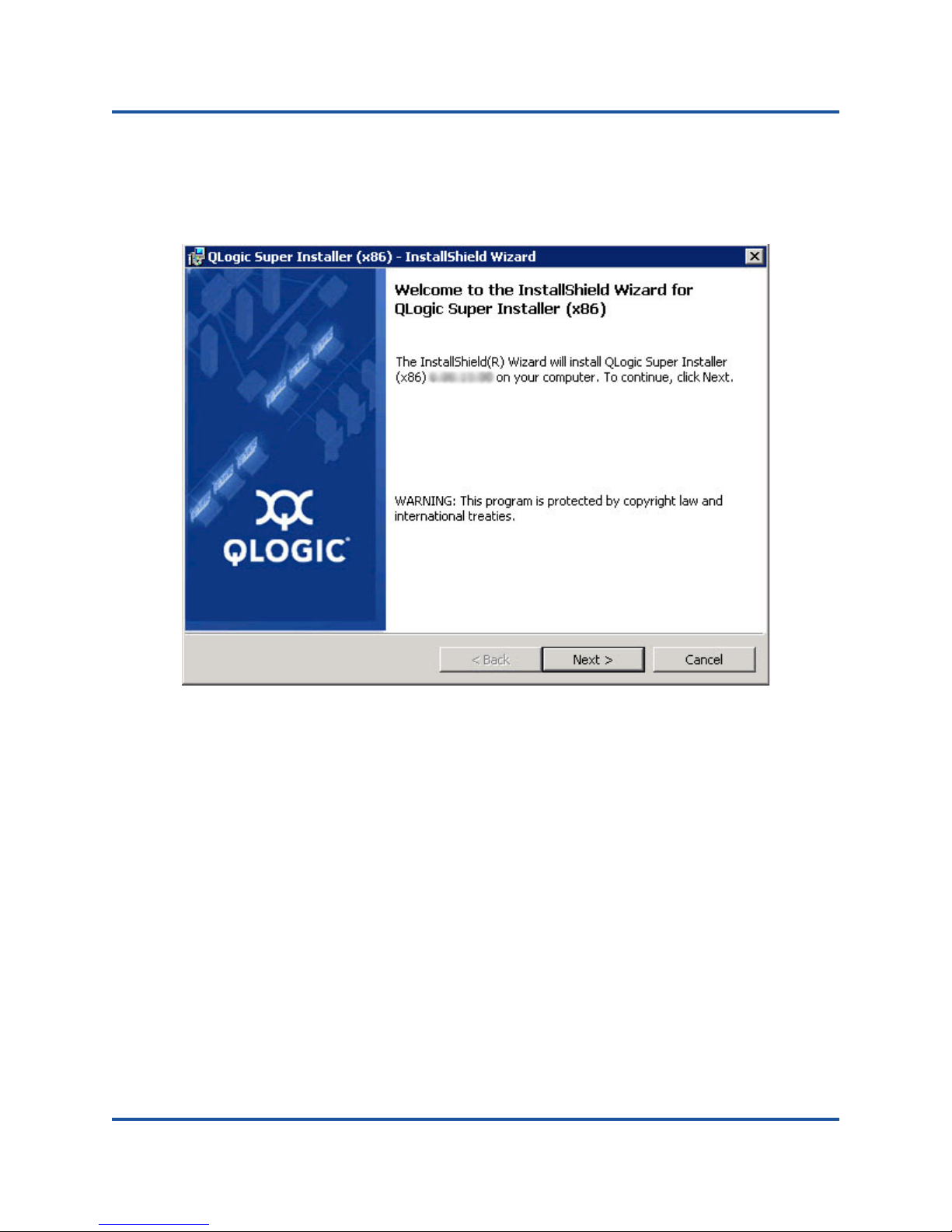
2. Click Install to continue.
The QLogic Super Installer—InstallShield
Figure 2-2.
®
Wizard appears, as shown in
Figure 2-2. QLogic Super Installer—InstallShield Wizard
6 CU0354602-00 L
Page 22
2–Driver Installation and Configuration
Windows Driver Installation and Configuration
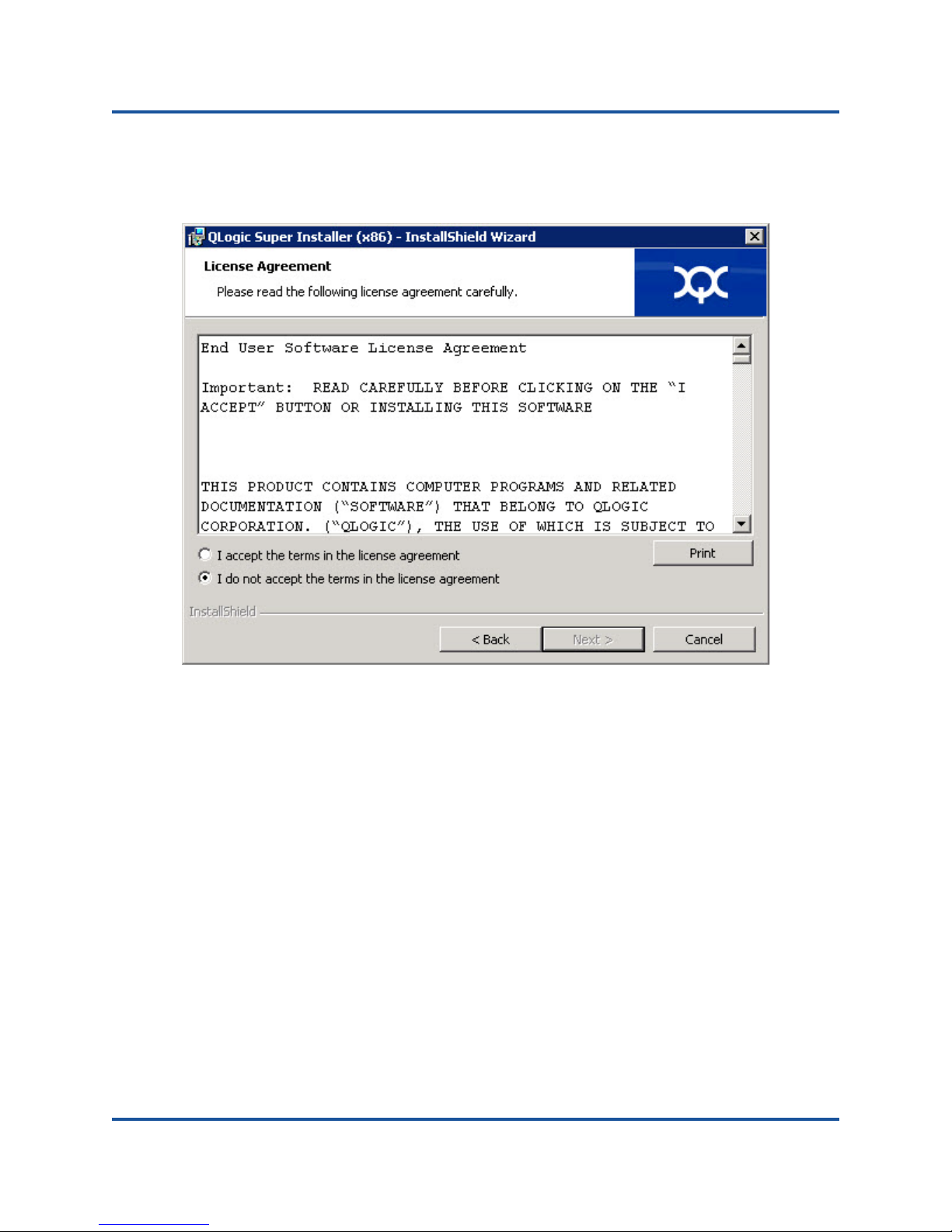
3. Click Next to continue.
The License Agreement dialog box appears, as shown in Figure 2-3.
Figure 2-3. License Agreement Dialog Box
7 CU0354602-00 L
Page 23
2–Driver Installation and Configuration
Windows Driver Installation and Configuration
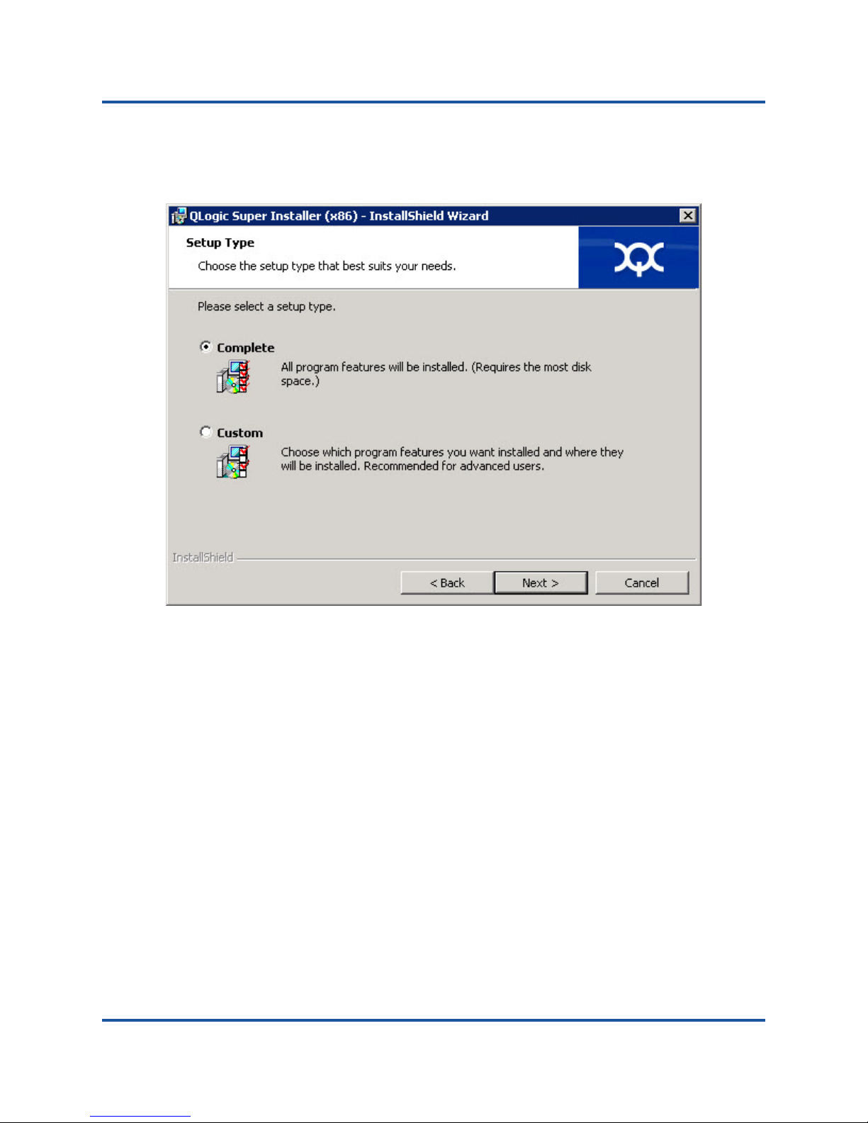
4. Select I accept the terms of the license agreement and click Next.
The Setup Type dialog box appears, as shown in Figure 2-4.
Figure 2-4. Setup Type Dialog Box
a. Select a setup type as follows:
Select Complete to install all program features.
Select Custom to manually select the features to be installed.
b. Click Next to continue.
If you selected Complete, proceed directly to Step 5.
8 CU0354602-00 L
Page 24

2–Driver Installation and Configuration
Windows Driver Installation and Configuration
c. The Custom Setup dialog box appears, as shown in Figure 2-5.
Figure 2-5. Custom Setup Dialog Box
d. Select the features to install. By default, all features are selected. To
change a feature’s install setting, click the icon next to it and select one
of the following:
This feature will be installed on the local hard drive—This
setting marks the feature for installation
This feature, and all subfeatures, will be installed on the
local hard drive—This setting marks the feature and all of its
subfeatures for installation
This feature will not be available—This setting prevents the
feature from being installed.
e. Click Next to continue.
9 CU0354602-00 L
Page 25
2–Driver Installation and Configuration
Windows Driver Installation and Configuration
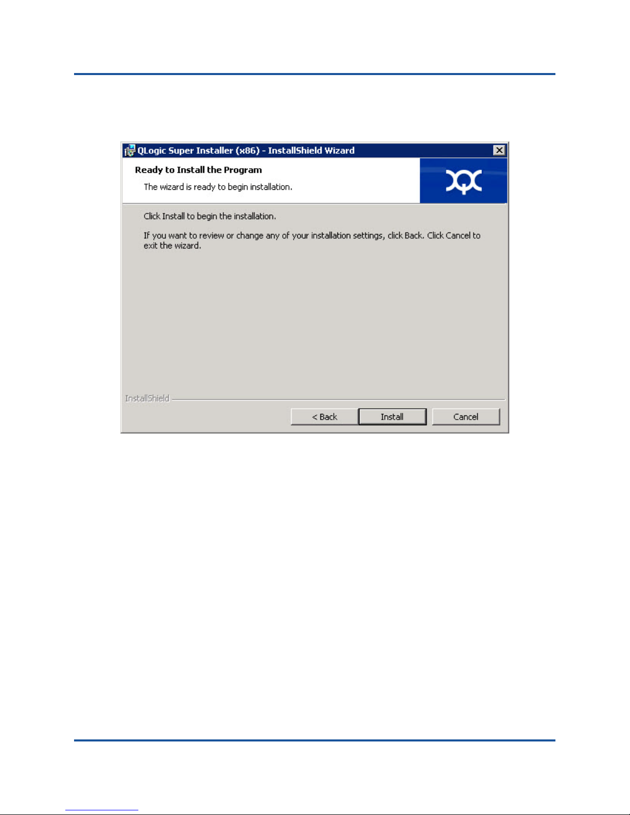
5. The Ready to Install the Program dialog box appears, as shown in
Figure 2-6.
Figure 2-6. Ready to Install the Program Dialog Box
10 CU0354602-00 L
Page 26
2–Driver Installation and Configuration
Windows Driver Installation and Configuration
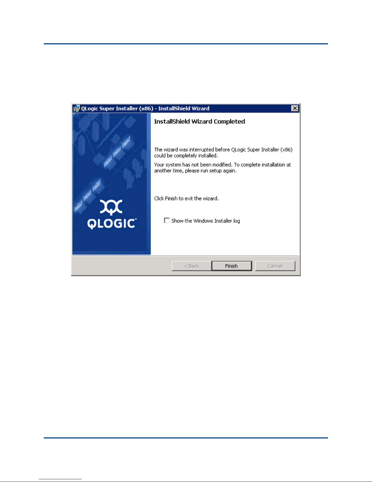
6. Click Install so that the InstallShield Wizard installs the QLogic Adapter
drivers and Management Software Installer.
When the installation is complete, the InstallShield Wizard Completed dialog
box appears, as shown in Figure 2-7.
Figure 2-7. InstallShield Wizard Complete Dialog Box
11 CU0354602-00 L
Page 27
2–Driver Installation and Configuration
NOTE
Windows Driver Installation and Configuration
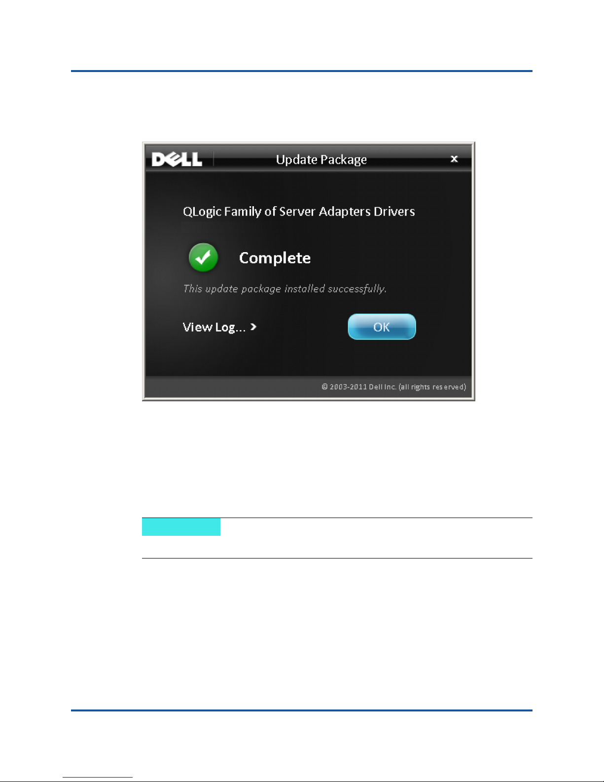
7. Click Finish to dismiss the installer.
The Update Package window appears, as shown in Figure 2-8.
Figure 2-8. Update Package Window
8. Click OK to close the window.
Running the DUP from the Command Line
Running the DUP from the command line, with no options specified, results in the
same behavior as double-clicking the icon representing the DUP.
The actual file name of the DUP varies.
To run the DUP from the command line:
C:\><DUP_file_name>.EXE
12 CU0354602-00 L
Page 28

2–Driver Installation and Configuration
NOTE
NOTE
NOTE
Windows Driver Installation and Configuration
The following is the syntax for specifying options to customize the DUP installation
behavior:
<DUP_file_name>.exe [/<option1>[=<value1>]]
[/<option2>[=<value2>]]...
To display the GUI for guided installation, update, or extraction, use no options.
Options
The following options can be used to customize the DUP installation behavior.
To update the DUP usage information:
/? or /h
To suppress the DUP GUI:
/s
To extract update contents to a directory:
/e=<path>
This command requires the /s option.
To extract only the driver components to a directory:
/drivers=<path>
This command requires the /s option.
To install/update only the driver components:
/driveronly
This command requires the /s option.
(Advanced) This command sends all text following the /passthrough option
directly to the QLogic installation software of the DUP. This mode suppresses any
provided GUI but not necessarily those of the QLogic software.
/passthrough
13 CU0354602-00 L
Page 29

2–Driver Installation and Configuration
NOTE
NOTE
Windows Driver Installation and Configuration
(Advanced) To return a coded description of this DUP’s supported features:
/capabilities
This command requires the /s option.
To define a specific path for the DUP’s log file:
/l=<path>
This option cannot be used in combination with /passthrough or
/capabilities.
Examples
To update the system silently:
<DUP_file_name>.exe /s
To extract the update contents to the C:\mydir\ directory:
<DUP_file_name>.exe /s /e=C:\mydir
To extract the driver components to the C:\mydir\ directory:
<DUP_file_name>.exe /s /drivers=C:\mydir
To install only the driver components:
<DUP_file_name>.exe /s /driveronly
To change from the default log location to C:\my path with
spaces\log.txt:
<DUP_file_name>.exe /l="C:\my path with spaces\log.txt"
14 CU0354602-00 L
Page 30

2–Driver Installation and Configuration
NOTE
Linux Driver Installation and Configuration
Linux Driver Installation and Configuration
This section provides the following procedures for installing drivers on a Linux
system:
Installation Overview
Installing the Linux NIC Driver
Installing the Linux iSCSI Driver
Installing the Linux FCoE Driver
Installation Overview
To install and configure the adapter drivers on a Linux system, refer to the driver
release notes, readme, and installation instructions included in the package.
To install the Red Hat Package Manager (RPM), issue the following
command as a root user:
# rpm -Uvh <rpm name>
For example:
# rpm -Uvh qla2xxx-kmp-default-<driver-version_kernel-
version>-<release>.x86_64.rpm
To uninstall the RPM, issue the following command as a root user:
# rpm -e <rpm>
For example:
# rpm -e qla2xxx-kmp-default-<driver-version_kernel-
version>-<release>
Installing the Linux NIC Driver
To install the Linux NIC driver, refer to the instructions (INSTALL.qlcnic)
provided with the individual driver package.
15 CU0354602-00 L
Page 31

2–Driver Installation and Configuration
Linux Driver Installation and Configuration
Installing the Linux iSCSI Driver
Driver installation makes extensive use of the build.sh script located in the
driver source (extras/build.sh). This section provides installation instructions
for the following Linux versions:
Building the iSCSI Adapter Driver SLES 11 SP4
Building the iSCSI Adapter Driver for RHEL 6.5 and SLES 12
Building the iSCSI Adapter Driver for RHEL 6.5 and SLES 11 SP3
Building the iSCSI Adapter Driver SLES 11 SP4
Building and Installing the Adapter Driver
1. Issue the following commands from the directory that contains the driver
package file, qla4xxx-src-x.xx.xx.xx.xx.xx-k.tar.gz:
# tar -xzvf qla4xxx-vx.xx.xx.xx.xx.xx-kx.tar.gz
# cd qla4xxx-vx-x.xx.xx.xx.xx.xx-kx
# tar -xvzf qla4xxx-src-vxx.xx.xx.xx.xx-ky.tar.gz
# cd qla4xxx-vx.xx.xx.xx.xx.xx-kx
where x.xx.xx.xx.xx.xx is the applicable version number.
2. Build and install the driver modules from the source code by executing the
build.sh script as follows:
# ./extras/build.sh install
The build.sh script does the following:
Builds the driver .ko files
Copies the .ko files to the appropriate directory:
/lib/modules/2.6.../extra/qlgc-qla4xxx
Adds the appropriate directive in the modprobe.conf file (if
applicable)
Manually Loading the Adapter Driver
1. Load the driver using one of the following methods:
To directly load the driver from the local build directory, issue the
following commands:
# insmod
/lib/modules/2.6.../kernel/drivers/scsi/scsi_transport_is
csi2.ko
# insmod qla4xxx.ko
16 CU0354602-00 L
Page 32

2–Driver Installation and Configuration
NOTE
Linux Driver Installation and Configuration
To load the driver using modprobe, issue the following command:
# modprobe -v qla4xxx
2. If the iqlremote agent was previously running, restart the agent by issuing
the following command (to ensure that the QConvergeConsole GUI can
reconnect to this host):
# service iqlremote start
Unloading the Adapter Driver
To replace an existing inbox driver with a new out-of-box iSCSI driver, unload the
existing driver and load the new driver. To unload the driver, stop all applications
using the driver and then unload the driver.
1. If the iqlremote agent is running, stop the agent by issuing the following
command:
# service iqlremote stop
2. To unload the driver using modprobe, issue the following command:
# modprobe -r qla4xxx
Rebuilding the RAM Disk with the New Driver
1. Edit the /etc/modprobe.conf file and add the following entry (if it is not
present):
alias scsi_hostadapterX qla4xxx
Where X is based on the order of the SCSI modules being loaded.
2. To create a backup copy of the RAM disk image, issue the following
commands:
# cd /boot
# cp initrd-[kernel version].img initrd-[kernel
version].img.bak
3. Rebuild the initrd image by issuing the following commands:
# mkinitrd -f initrd-[kernel version].img `uname -r`
4. Reboot to boot from the new initrd image and new driver.
Depending on the server hardware, the RAMDISK file name might be
different.
17 CU0354602-00 L
Page 33

2–Driver Installation and Configuration
Linux Driver Installation and Configuration
Building the iSCSI Adapter Driver for RHEL 6.5 and SLES 12
Building and Installing the Adapter Driver
1. Issue the following commands from the directory that contains the source
driver file, qla4xxx-src-vx.xx.xx.xx.xx.xx-k.tar.gz:
# tar -xzvf qla4xxx-vx.xx.xx.xx.xx.xx-cx.tar.gz
# cd qla4xxx-vx.xx.xx.xx.xx.xx-cx
where x.xx.xx.xx.xx.xx is the applicable version number.
2. Build and install the driver modules from the source code by executing the
build.sh script as follows:
# ./extras/build.sh install
The build.sh script does the following:
Builds the driver .ko files
Copies the .ko files to the appropriate directory:
For RHEL 6.5:
/lib/modules/2.6.../extra/qlgc-qla4xxx/
For SLES 12:
/lib/modules/2.6.../updates
Adds the appropriate directive in the modprobe.conf file (if
applicable)
18 CU0354602-00 L
Page 34

2–Driver Installation and Configuration
Linux Driver Installation and Configuration
Manually Loading the Adapter Driver
1. To load the driver, use one of the following methods:
To load the driver directly from the local build directories, issue the
following commands:
For RHEL 6.5:
# insmod /lib/modules/2.6.../kernel/drivers/scsi/
scsi_transport_iscsi.ko
insmod
/lib/modules/2.6.../extra/qlgc-qla4xxx/qla4xxx.ko
For SLES 12:
# insmod /lib/modules/2.6.../kernel/drivers/scsi/
scsi_transport_iscsi.ko
# insmod /lib/modules/2.6.../updates/qla4xxx.ko
To load the driver using modprobe, issue the following command:
# modprobe -v qla4xxx
2. If the iqlremote agent was previously running, restart the agent by issuing
the following command (to ensure that the QConvergeConsole GUI can
reconnect to this host):
# service iqlremote start
Unloading the Adapter Driver
To replace an existing inbox driver with a new out-of-box iSCSI driver, unload the
existing driver and load the new driver. To unload the driver, stop all applications
using the driver and then unload the driver.
1. If the iqlremote agent is running, stop the agent by issuing the following
command:
# service iqlremote stop
2. To unload the driver using modprobe, issue the following command:
# modprobe -r qla4xxx
19 CU0354602-00 L
Page 35

2–Driver Installation and Configuration
NOTE
Linux Driver Installation and Configuration
Rebuilding the RAM Disk
To automatically load the driver by rebuilding the RAM disk to include the driver,
follow these steps:
1.
To create a backup copy of the RAM disk image, issue the following command:
For RHEL 6.5:
# cd /boot
# cp initramfs-[kernel version].img initramfs-[kernel
version].img.bak
For SLES 12:
# cd /boot
# cp initrd-[kernel version].img initrd-[kernel
version].img.bak
2. Rebuild the initrd image with driver by issuing the following command:
For RHEL 6.5:
# mkinitrd -f /boot/initramfs-[kernel version].img 'uname
-r'
For SLES 12:
# mkinitrd
3. Reboot the host to boot from the new initrd image with new driver.
Depending on the server hardware, the RAMDISK file name might be
different.
Building the iSCSI Adapter Driver for RHEL 6.5 and SLES 11 SP3
Building and Installing the Adapter Driver
1. Issue the following commands from the directory that contains the source
driver file, qla4xxx-src-vx.xx.xx.xx.xx.xx-k.tar.gz:
# tar -xzvf qla4xxx-vx.xx.xx.xx.xx.xx-cx.tar.gz
# cd qla4xxx-vx.xx.xx.xx.xx.xx-cx
where x.xx.xx.xx.xx.xx is the applicable version number.
20 CU0354602-00 L
Page 36

2–Driver Installation and Configuration
Linux Driver Installation and Configuration
2. Build and install the driver modules from the source code by executing the
build.sh script as follows:
# ./extras/build.sh install
The build.sh script does the following:
Builds the driver .ko files
Copies the .ko files to the appropriate directory:
For RHEL 6.5:
/lib/modules/2.6.../extra/qlgc-qla4xxx/
For SLES 11 SP3:
/lib/modules/2.6.../updates
Adds the appropriate directive in the modprobe.conf file (if
applicable)
Manually Loading the Adapter Driver
1. To load the driver, use one of the following methods:
To load the driver directly from the local build directories, issue the
following commands:
For RHEL 6.5:
# insmod /lib/modules/2.6.../kernel/drivers/scsi/
scsi_transport_iscsi.ko
insmod
/lib/modules/2.6.../extra/qlgc-qla4xxx/qla4xxx.ko
For SLES 11 SP3:
# insmod /lib/modules/2.6.../kernel/drivers/scsi/
scsi_transport_iscsi.ko
# insmod /lib/modules/2.6.../updates/qla4xxx.ko
To load the driver using modprobe, issue the following command:
# modprobe -v qla4xxx
2. If the iqlremote agent was previously running, restart the agent by issuing
the following command (to ensure that the QConvergeConsole GUI can
reconnect to this host):
# service iqlremote start
21 CU0354602-00 L
Page 37

2–Driver Installation and Configuration
NOTE
Linux Driver Installation and Configuration
Unloading the Adapter Driver
To replace an existing inbox driver with a new out-of-box iSCSI driver, unload the
existing driver and load the new driver. To unload the driver, stop all applications
using the driver and then unload the driver.
1. If the iqlremote agent is running, stop the agent by issuing the following
command:
# service iqlremote stop
2. To unload the driver using modprobe, issue the following command:
# modprobe -r qla4xxx
Rebuilding the RAM Disk
To automatically load the driver by rebuilding the RAM disk to include the driver,
follow these steps:
1.
To create a backup copy of the RAM disk image, issue the following command:
For RHEL 6.5:
# cd /boot
# cp initramfs-[kernel version].img initramfs-[kernel
version].img.bak
For SLES 11 SP3:
# cd /boot
# cp initrd-[kernel version].img initrd-[kernel
version].img.bak
2. Rebuild the initrd image with driver by issuing the following command:
For RHEL 6.5:
# mkinitrd -f /boot/initramfs-[kernel version].img 'uname
-r'
For SLES 11 SP3:
# mkinitrd
3. Reboot the host to boot from the new initrd image with new driver.
Depending on the server hardware, the RAMDISK file name might be
different.
22 CU0354602-00 L
Page 38

2–Driver Installation and Configuration
Linux Driver Installation and Configuration
Installing the Linux FCoE Driver
This section provides procedures for installing the Linux FCoE driver for the
following operating systems:
Building the Driver for RHEL 6.5 Linux
Building the Driver for SLES 11 SP4 Linux
Building the Driver for SLES 12 Linux
Building the Driver for SLES 11 SP3 Linux
Building the Driver for RHEL 6.5 Linux
1. Issue the following commands from the directory that contains the source
driver file, qla2xxx-src-x.xx.xx.xx.xx.xx-k.gz:
# tar -xzvf qla2xxx-src-x.xx.xx.xx.xx.xx-k.tar.gz
# cd qla2xxx-src-x.xx.xx.xx.xx.xx-k
where x.xx.xx.xx.xx.xx is the applicable version number.
2. Build and install the driver modules from the source code by executing the
build.sh script as follows:
# ./extras/build.sh install
The build.sh script does the following:
Builds the driver .ko files.
Copies the .ko files to the appropriate
/lib/modules/2.6.../extra/qlgc-qla2xxx directory.
3. Manually load the driver for Linux by issuing the following command:
# modprobe -v qla2xxx
To unload the driver, issue the following command:
# modprobe -r qla2xxx
4. To automatically load the driver each time the system boots, rebuild the
RAM disk to include the driver as follows:
a. Create a backup copy of the RAMDISK image by issuing the following
commands:
# cd /boot
# cp initramfs-[kernel version].img initramfs-[kernel
version].img.bak
b. Create the new RAMDISK by issuing the following command:
# dracut -f
23 CU0354602-00 L
Page 39

2–Driver Installation and Configuration
Linux Driver Installation and Configuration
c. To load the driver, reboot the host.
Building the Driver for SLES 11 SP4 Linux
1. Issue the following commands from the directory that contains the source
driver file, qla2xxx-src-vx.xx.xx.xx.xx.x-k4.tar.gz:
# tar -xzvf qla2xxx-src-vx.xx.xx.xx.xx.x-k4.tar.gz
# cd qla2xxx-x.xx.xx.xx.xx.x-k4
where x.xx.xx.xx.xx.x is the applicable version number.
2. Build and install the driver modules from the source code by executing the
build.sh script as follows:
# ./extras/build.sh install
The build.sh script does the following:
Builds the driver .ko files.
Copies the .ko files to the appropriate
/lib/modules/2.6.../updates directory.
Adds the appropriate directive in the modprobe.conf file (if
applicable).
3. Manually load the driver for Linux.
To load the driver using modprobe, issue the following command:
# modprobe -v qla2xxx
To unload the driver using modprobe, issue the following command:
# modprobe -r qla2xxx
4. To automatically load the driver each time the system boots, rebuild the
RAM disk to include the driver as follows:
a. Edit the /etc/sysconfig/kernel file to modify the
INITRD_MODULES directive and append qla2xxx to the string. For
example:
INITRD_MODULES=".... qla2xxx"
where qla2xxx is appended to the end of the directive.
b. Create a backup copy of the RAMDISK image by issuing the following
commands:
# cd /boot
# cp initrd-[kernel version] initrd-[kernel version].bak
# mkinitrd
24 CU0354602-00 L
Page 40

2–Driver Installation and Configuration
NOTE
Linux Driver Installation and Configuration
Depending on the server hardware, the RAMDISK file name
might be different.
c. To load the driver, reboot the host.
Building the Driver for SLES 12 Linux
1. In the directory that contains the source driver file,
qla2xxx-src-vx.xx.xx.xx.11.x-k.tgz, issue the following
commands:
# tar -xzvf qla2xxx-src-vx.xx.xx.xx.11.x-k.tgz
# cd qla2xxx-x.xx.xx.xx.xx.xx-k
where x.xx.xx.xx.xx.xx is the applicable version number.
2. Build and install the driver modules from the source code by executing the
build.sh script as follows:
# ./extras/build.sh install
The build.sh script does the following:
Builds the driver .ko files.
Copies the .ko files to the appropriate
/lib/modules/3.x.../updates directory.
Adds the appropriate directive in the modprobe.conf file (if
applicable).
3. Manually load the driver for Linux.
Edit the /etc/modprobe.d/unsupported_modules file to make
the following change:
allow_unsupported_modules 1 (replace 0 by 1)
To load the driver using modprobe, issue the following command:
# modprobe -v qla2xxx
To unload the driver using modprobe, issue the following command:
# modprobe -r qla2xxx
25 CU0354602-00 L
Page 41

2–Driver Installation and Configuration
NOTE
Linux Driver Installation and Configuration
4. To automatically load the driver each time the system boots, rebuild the
RAM disk to include the driver.
Create a copy of the current RAMDISK by issuing the following commands:
# cd /boot
# cp initrd-[kernel version].img initrd-[kernel
version].img.bak
# mkinitrd
Depending on the server hardware, the RAMDISK file name might be
different.
5. To load the driver, reboot the host.
Building the Driver for SLES 11 SP3 Linux
1. In the directory that contains the source driver file,
qla2xxx-src-vx.xx.xx.xx.11.x-k.tgz, issue the following
commands:
# tar -xzvf qla2xxx-src-vx.xx.xx.xx.11.x-k.tgz
# cd qla2xxx-x.xx.xx.xx.xx.xx-k4
where x.xx.xx.xx.xx.xx is the applicable version number.
2. Build and install the driver modules from the source code by executing the
build.sh script as follows:
# ./extras/build.sh install
The build.sh script does the following:
Builds the driver .ko files.
Copies the .ko files to the appropriate
/lib/modules/3.x.../updates directory.
Adds the appropriate directive in the modprobe.conf file (if
applicable).
3. Manually load the driver for Linux.
Edit the /etc/modprobe.d/unsupported_modules file to make
the following change:
allow_unsupported_modules 1 (replace 0 by 1)
26 CU0354602-00 L
Page 42

2–Driver Installation and Configuration
NOTE
Linux Driver Installation and Configuration
To load the driver using modprobe, issue the following command:
# modprobe -v qla2xxx
To unload the driver using modprobe, issue the following command:
# modprobe -r qla2xxx
4. To automatically load the driver each time the system boots, rebuild the
RAM disk to include the driver.
Create a copy of the current RAMDISK by issuing the following commands:
# cd /boot
# cp initrd-[kernel version].img initrd-[kernel
version].img.bak
# mkinitrd
Depending on the server hardware, the RAMDISK file name might be
different.
5. To load the driver, reboot the host.
27 CU0354602-00 L
Page 43

2–Driver Installation and Configuration
NOTE
VMware Driver Installation and Configuration
VMware Driver Installation and Configuration
This section provides the following procedures for installing drivers on a VMware
system:
Installation Overview
Installing the ESXi 5.x NIC Driver
Installing the ESXi 5.x iSCSI Driver
Installing the ESXi 5.x FCoE Driver
Installing the ESXi 6.x Fibre Channel Over Ethernet Driver
Installing the ESXi 6.x iSCSI Driver
Installing the QConvergeConsole VMware vCenter Server Plug-in
Installing the vSphere Web Client Plug-in
Installation Overview
To install and configure the adapter drivers on a VMware system, refer to the
driver release notes and readme files included in the package.
Installing the ESXi 5.x NIC Driver
The operating system manages and controls the driver installation process. To
install the ESXi 5.x driver, follow the steps in this section.
This section provides the most common ways of installing and upgrading the
driver. For other installation procedures, refer to the following:
http://kb.vmware.com/selfservice/microsites/search.do?language=en_US&c
md=displayKC&externalId=2005205
This section provides procedures for the following:
Updating an Existing Driver or Installing a New Driver for an Existing ESXi
Installation with esxcli (ESXi 5.x Only)
Verifying the Version of the Installed Driver (ESXi 5.x Only)
For other installation procedures, consult the operating system manuals and the
driver readme file for more details.
28 CU0354602-00 L
Page 44

2–Driver Installation and Configuration
VMware Driver Installation and Configuration
Updating an Existing Driver or Installing a New Driver for an Existing ESXi
Installation with esxcli (ESXi 5.x Only)
To use the driver bundle (<offline-bundle>):
1. Copy the driver bundle (
2. Install the driver bundle (
<offline-bundle>) to this ESXi host.
<offline-bundle>) using the following steps:
a. Type the following command to make a temporary directory:
mkdir /install; cd /install
b. Unzip the driver bundle in the temporary directory:
/install : unzip <offline-bundle>
c. Run the following command:
esxcli software vib install –d /install/offline-bundle.zip
To use the driver VIB:
1. Copy the driver VIB
(net
-
<offline-bundle>
6_64.vib
) to this ESXi host.
-<driver-version>.0.0.<esx-build>.x8
2. Install the driver VIB using the following esxcli commands:
a. Type the following command to make a temporary directory:
mkdir /install; cd /install
b. Run the following command:
esxcli software vib install -v /install/<driver-vib>
Verifying the Version of the Installed Driver (ESXi 5.x Only)
Verify the installed package in the system using the following command:
esxcli software vib list | grep -i driver version
The driver version is embedded in the VIB version.
For example, the output looks like the following:
esxcli software vib list | grep qlc
net-qlcnic 5.1.132-1OEM.500.0.0.472560 VMware
VMwareCertified 2012-12-19
29 CU0354602-00 L
Page 45

2–Driver Installation and Configuration
NOTE
VMware Driver Installation and Configuration
Installing the ESXi 5.x iSCSI Driver
The operating system manages and controls the driver installation process. To
install the ESXi 5.x driver, follow the steps in this section.
This section provides the most common ways of installing and upgrading the
driver. For other installation procedures, refer to the following:
http://kb.vmware.com/selfservice/microsites/search.do?language=en_US&c
md=displayKC&externalId=2005205
This section provides procedures for the following:
Updating an Existing Driver or Installing a New Driver for an Existing ESXi
Installation with esxcli (ESXi 5.x Only)
Verifying the Version of the Installed Driver (ESXi 5.x Only)
For other installation procedures, consult the operating system manuals and the
driver readme file for more details.
Updating an Existing Driver or Installing a New Driver for an Existing ESXi
Installation with esxcli (ESXi 5.x Only)
To use the driver bundle (<offline-bundle>):
1. Copy the driver bundle (
2. Install the driver bundle (
a. Type the following command to make a temporary directory:
mkdir /install; cd /install
b. Unzip the driver bundle in the temporary directory:
/install : unzip <offline-bundle>
c. Run the following command:
esxcli software vib install –d /install/offline-bundle.zip
<offline-bundle>) to this ESXi host.
<offline-bundle>) using the following steps:
30 CU0354602-00 L
Page 46

2–Driver Installation and Configuration
VMware Driver Installation and Configuration
To use the driver VIB:
1. Copy the driver VIB
(
scsi-
86_64.vib
<offline-bundle>
) to this ESXi host.
-<driver-version>.0.0.<esx-build>.x
2. Install the driver VIB using the following esxcli commands:
a. Type the following command to make a temporary directory:
mkdir /install; cd /install
b. Run the following command:
esxcli software vib install -v /install/<driver-vib>
Verifying the Version of the Installed Driver (ESXi 5.x Only)
Verify the installed package in the system using the following command:
esxcli software vib list | grep -i driver version
The driver version is embedded in the VIB version.
For example, the output looks like the following:
# esxcli software vib list | grep qla4xxx
scsi_qla4xxx .01.03.2-6vmw.550.0.0.1014658 VMware VMwareCertified
2013-02-2
31 CU0354602-00 L
Page 47

2–Driver Installation and Configuration
NOTE
VMware Driver Installation and Configuration
Installing the ESXi 5.x FCoE Driver
The operating system manages and controls the driver installation process. To
install the ESXi 5.x driver, follow the steps in this section.
This section provides the most common ways of installing and upgrading the
driver. For other installation procedures, refer to the following:
http://kb.vmware.com/selfservice/microsites/search.do?language=en_US&c
md=displayKC&externalId=2005205
This section provides procedures for the following:
Updating an Existing Driver or Installing a New Driver for an Existing ESXi
Installation with esxcli (ESXi 5.x Only)
Verifying the Version of the Installed Driver (ESXi 5.x Only)
For other installation procedures, consult the operating system manuals and the
driver readme file for more details.
Updating an Existing Driver or Installing a New Driver for an Existing ESXi
Installation with esxcli (ESXi 5.x Only)
To use the driver bundle (<offline-bundle>.zip):
1. Copy the driver bundle (<offline-bundle>.zip) to this ESXi host.
2. Install using the driver bundle (<offline-bundle>.zip):
a. Type the following command to make a temporary directory:
$ mkdir /install
$ mv <offline-bundle>.zip /install
$ cd install
b. Unzip the driver bundle in the temporary directory:
$ unzip <offline-bundle>.zip
c. Run one of the following commands.
For ESX 5.0/5.1:
esxcli software vib install -n scsi-qla2xxx -d
/install/offline-bundle.zip
For ESX 5.5:
esxcli software vib install -n qlnativefc -d
/install/offline-bundle.zip
32 CU0354602-00 L
Page 48

2–Driver Installation and Configuration
VMware Driver Installation and Configuration
To use the driver VIB:
1. Copy the driver VIB (for ESX 5.0/5.1:
scsi-qla2xxx-<driver-version>.0.0.<esx-build>.x86_64.vib
for ESX 5.5:
qlnativefc-<driver-version>.0.0.<esx-build>.x86_64.vib)
to this ESXi host.
2. Install the driver VIB using the following esxcli commands:
a. Type the following command to make a temporary directory:
mkdir /install; cd /install
b. Run the following command:
$ esxcli software vib install -v <driver-vib-file>
For example:
esxcli software vib install -v
/vmfs/volumes/datastore1/scsi-qla2xxx-934.5.10.0-1OEM.500
.0.0.472560.x86_64.vib
;
Verifying the Version of the Installed Driver (ESXi 5.x Only)
Verify the installed package in the system using the following command:
esxcli software vib list | grep -i <driver-version / driver name>
The driver version is embedded in the VIB version.
For example, the output looks like the following:
# esxcli software vib list | grep qla2xxx
scsi-qla2xxx 911.k1.1-16vmw.500.0.0.406165 VMware
VMwareCertified 2011-09-21
33 CU0354602-00 L
Page 49

2–Driver Installation and Configuration
VMware Driver Installation and Configuration
Installing the ESXi 6.x Fibre Channel Over Ethernet Driver
Updating an Existing Driver or Installing a New Driver for an Existing ESXi
Installation with esxcli (for ESXi 6x Only)
To use the driver bundle <offline-bundle>.zip):
1. Copy the driver bundle (<offline-bundle>.zip) to this ESXi host.
2. Install the driver bundle (<offline-bundle>.zip) using the following
steps:
a. Type the following command to make a temporary directory:
$ mkdir /install $ mv <offline-bundle>.zip /install $ cd
install
b. Unzip the driver bundle in the temporary directory:
$ unzip <offline-bundle>.zip
c. Run one of the following commands.
For ESX 6.x:
esxcli software vib install -n qlnativefc -d /install
To use the driver VIB:
1. Copy the driver VIB (for ESX 6.0:
qlnativefc-<driver-version>.0.0.<esx-build>.x86_64.vib)
to this ESXi host.
2. Install the driver VIB using the following esxcli commands:
a. Type the following command to make a temporary directory:
mkdir /install; cd /install
b. Run the following command:
esxcli software vib install -v <driver-vib-file>
For example, the output looks like the following:
esxcli software vib install -v
/vmfs/volumes/datastore1/qlnativefc-2.1.23.0-1OEM.6
00.0.0.2159203.x86_64.vib
34 CU0354602-00 L
Page 50

2–Driver Installation and Configuration
VMware Driver Installation and Configuration
Installing the ESXi 6.x iSCSI Driver
Updating an Existing Driver or Installing a New Driver for an Existing ESXi
Installation with esxcli (for ESXi 6x Only)
To use the driver bundle <offline-bundle>.zip):
1. Copy the driver bundle (<offline-bundle>.zip) to this ESXi host.
2. Install the driver bundle (<offline-bundle>.zip) using the following
steps:
a. Type the following command to make a temporary directory:
$ mkdir /install $ mv <offline-bundle>.zip /install $ cd
install
b. Unzip the driver bundle in the temporary directory:
$ unzip <offline-bundle>.zip
c. Run one of the following commands.
For ESX 6.x:
esxcli software vib install -n scsi-qla4xxx -d /install
To use the driver VIB:
1. Copy the driver VIB (for ESX 6.0:
scsi-qla4xxx_-<driver-version>.<esx-build>.vib) to this
ESXi host.
2. Install the driver VIB using the following esxcli commands:
a. Type the following command to make a temporary directory:
mkdir /install; cd /install
b. Run the following command:
esxcli software vib install -v <driver-vib-file>
For example, the output looks like the following:
esxcli software vib install -v
/vmfs/volumes/datastore1/scsi-qla4xxx_644.6.04.0-1O
EM.600.0.0.2159203.vib
35 CU0354602-00 L
Page 51

2–Driver Installation and Configuration
VMware Driver Installation and Configuration
Installing the QConvergeConsole VMware vCenter
Server Plug-in
To use the QConvergeConsole VMware vCenter Server Plug-in, install the
following software in the order given:
1. QConvergeConsole VMware vCenter Server Plug-in—on the vCenter
Server
2. QLogic Adapter CIM Provider—on the ESX/ESXi server
The following topics explain how to install and uninstall the required software:
Installation Package Contents
QConvergeConsole VMware vCenter Server Plug-in Installation
Plug-in Unregistration from a Manual Install
Enabling and Disabling the Plug-in
Uninstalling the QConvergeConsole VMware vCenter Server Plug-in
Installing the QLogic Adapter CIM Provider
Uninstalling the QLogic Adapter CIM Provider
For information on installing the Plug-in, refer to “QConvergeConsole VMware
vCenter Server Plug-in Installation” on page 37.
Installation Package Contents
The latest version of the QLogic Adapter CIM Provider and QConvergeConsole
VMware vCenter Server Plug-in package contains the files needed to install both
the Plug-in and the CIM Provider. The files are as follows (x_x_x is the version
number):
QLogic_Adapter_VI_Plugin_x_x_x.exe
This file is the QConvergeConsole VMware vCenter Server Plug-in
installation package.
qlogic_adapter_provider_vmware_esx50x-x.x.x
This file contains the QLogic Adapter CIM Provider installation package for
ESXi 5.0.x/5.1.x, where x.x.x is the version of the CIM Provider.
qlogic_adapter_provider_vmware_esx55_60-x.x.x
This file contains the QLogic Adapter CIM Provider installation package for
ESXi 5.5, where x.x.x is the version of the CIM Provider.
readme.txt
This file is the Read Me document containing hardware and software
requirements, operating system support, supported features, installation and
removal instructions, known issues and workarounds, and support contact
information.
release_notes.txt
36 CU0354602-00 L
Page 52

2–Driver Installation and Configuration
VMware Driver Installation and Configuration
This file contains the release notes that list changes, fixes, known issues,
and release details.
For detailed information on installing the QConvergeConsole VMware vCenter
Server Plug-in, refer to “QConvergeConsole VMware vCenter Server Plug-in
Installation” on page 37.
For detailed information on installing the CIM Provider, refer to “Installing the
QLogic Adapter CIM Provider” on page 44.
QConvergeConsole VMware vCenter Server Plug-in Installation
To install the QConvergeConsole VMware vCenter Server Plug-in:
1. Download the QLogic_Adapter_VI_Plugin_x_x_x.exe file (where
x_x_x is the version number).
2. Run the installation by double-clicking the .exe file, by typing the name of
the .exe file in a Run window, or by clicking Browse and locating the .exe
file.
3. The InstallAnywhere wizard opens, as shown in Figure 2-9.
Figure 2-9. InstallAnywhere Initial Window
37 CU0354602-00 L
Page 53

2–Driver Installation and Configuration
VMware Driver Installation and Configuration
4. The Plug-in Registration Wizard opens, as shown in Figure 2-10. Click Next.
Figure 2-10. QConvergeConsole VMware vCenter Server Plug-in Registration Wizard
5. Wait while the wizard configures the plug-in (see Figure 2-11).
Figure 2-11. QConvergeConsole VMware vCenter Server Plug-in Configuration
38 CU0354602-00 L
Page 54

2–Driver Installation and Configuration
VMware Driver Installation and Configuration
6. Select the installation directory and then click Install (see Figure 2-12).
Figure 2-12. Select the Installation Directory
7. Wait while the wizard performs the installation (see Figure 2-13).
Figure 2-13. Installing the Plug-In
39 CU0354602-00 L
Page 55

2–Driver Installation and Configuration
VMware Driver Installation and Configuration
8. Type in the requested information and then click Next (see Figure 2-14).
Figure 2-14. User Input Screen
9. Wait while the wizard finishes configuring the plug-in (see Figure 2-15).
Figure 2-15. QConvergeConsole VMware vCenter Server Plug-in Configuration
40 CU0354602-00 L
Page 56

2–Driver Installation and Configuration
VMware Driver Installation and Configuration
10. Figure 2-16 appears when registration is completed. Click Finish to exit.
Figure 2-16. Successful Registration
11. After the installation completes, restart the TomcatTM service as follows:
If the plug-in is installed on the VMware vCenter Server, restart the
VMware Virtual Center Management Web services.
If the plug-in is installed on a server other than the vCenter Server,
restart the Apache Tomcat
Plug-in Unregistration from a Manual Install
If you have performed a manual install of the QConvergeConsole VMware
vCenter Server plug-in, you must perform a manual uninstall before running the
plug-in Installation Wizard.
VMware provides two type of scripts for plug-in registration (and unregistration):
For PowerShell scripting: http://communities.vmware.com/docs/DOC-4521
For Perl: http://communities.vmware.com/docs/DOC-4530
Before you can use the script, you need to download the appropriate VI SDK from
VMware:
For Perl VMware Infrastructure (VI) software development kit (SDK):
vSphere SDK for Perl
http://www.vmware.com/support/developer/viperltoolkit/
TM
service.
41 CU0354602-00 L
Page 57

2–Driver Installation and Configuration
NOTE
VMware Driver Installation and Configuration
For PowerShell: vSphere PowerCLI
http://communities.vmware.com/community/vmtn/vsphere/automationtools/
powercli
After downloading and installing the SDK and the registration script, follow the
VMware instructions to unregister the plug-in.
For example, the Perl unregister command is:
perl registerPlugin.pl --server="127.0.0.1"
-username="administrator" --password="password"
--key="com.qlogic.QLogicAdapterVIPlugIn" --action="remove"
Replace administrator and password with the correct information to log into
the vCenter Server.
Enabling and Disabling the Plug-in
If the plug-in installation completed successfully, you do not need to enable
the plug-in; it is automatically enabled during installation. You can, however,
verify if the plug-in is enabled by using the following procedure.
To enable or disable the QConvergeConsole VMware vCenter Server plug-in,
follow these steps:
1. In the vSphere Client window, click Plug-ins and then click Manage
Plug-ins.
The Plug-in Manager window appears, as shown in Figure 2-17.
Figure 2-17. Managing Plug-ins in vSphere Client
2. Locate the QConvergeConsole vCenter Server plug-in on the Installed
Plug-ins section of the window.
The plug-in’s status (Enabled or Disabled) is displayed in the Status column,
as shown in Figure 2-18.
42 CU0354602-00 L
Page 58

2–Driver Installation and Configuration
VMware Driver Installation and Configuration
Figure 2-18. QConvergeConsole vCenter Server in Plug-in Manager
3. If you want to enable or disable the QConvergeConsole plug-in, right-click
on the plug-in and select Enabled or Disabled (the status toggles between
the two), as shown in Figure 2-19.
4. Click Close to close the Plug-in Manager window.
Figure 2-19. Toggling the QConvergeConsole vCenter Server Plug-in Status
43 CU0354602-00 L
Page 59

2–Driver Installation and Configuration
NOTE
VMware Driver Installation and Configuration
Uninstalling the QConvergeConsole VMware vCenter Server Plug-in
To remove the QConvergeConsole VMware vCenter Server Plug-in:
1. In the Windows Control Panel, select Add or Remove Programs.
(Windows Server 2008 or later only: select Programs and Features.)
2. In the Add or Remove Programs dialog box, select the QConvergeConsole
VMware vCenter Server Plug-in and then click Change/Remove.
3. Follow the instructions in the QConvergeConsole VMware vCenter Server
Plug-in installer to remove the plug-in.
Installing the QLogic Adapter CIM Provider
This section describes how to install, start, and remove the QLogic Adapter CIM
Provider for VMware ESX and ESXi. There is more than one zip package, so
make sure that you pick the zip package that matches your
environment—ESXi 5.0, and ESXi 5.1.
The QLogic Adapter CIM Provider for VMware ESX was generated as a VIB
file. A VIB contains the complete set of files and binaries required to install
the provider on VMware ESX/ESXi. The offline-bundle.zip file
contains the VIB and the necessary metadata to install the provider on
VMware ESX/ESXi.
Initial Installation Methods
Initial installation methods for the CIM Provider include the following:
Online
Refer to “Installing the CIM Provider on an ESXi 5.x Host” on page 45 or
“Installing the CIM Provider on an ESXi 5.5 Host” on page 45.
Offline
Refer to “Existing ESX/ESXi Installation Using VMware Update Manager” on
page 45.
Remote
Refer to “Remote Installation of the CIM Provider on an ESX/ESXi Host” on
page 46.
44 CU0354602-00 L
Page 60

2–Driver Installation and Configuration
VMware Driver Installation and Configuration
Installing the CIM Provider on an ESXi 5.x Host
1. Copy the provider-adapter.vib file to the root directory (/) of the
ESXi 5.x system.
2. Issue the esxcli commands as follows:
# cd /
# esxcli software acceptance set --level=CommunitySupported
# esxcli software vib install -v file:/provider-adapter.vib
--maintenance-mode --no-sig-check
3. Reboot the system as required.
Installing the CIM Provider on an ESXi 5.5 Host
1. Copy the qlogic-adapter-provider.zip file to the root directory (/) of
the ESXi 5.5 system.
2. Issue the esxcli commands as follows:
# cd /
# esxcli software acceptance set --level=CommunitySupported
# esxcli software vib install -d
file:/qlogic-adapter-provider.zip --maintenance-mode
--no-sig-check
3. Reboot the system as required.
Existing ESX/ESXi Installation Using VMware Update Manager
An existing ESX/ESXi host has asynchronous drivers installed using VMware
Update Manager. For more information, see “Using vSphere ESX/ESXi Image
Builder CLI” in the vSphere Installation and Setup Guide
To install the asynchronous drivers:
1. Extract the contents of the asynchronous driver zip file.
2. Identify the offline-bundle.zip file(s).
3. From vCenter Server, select Home and then select Update Manager.
4. Click the Patch Repository tab.
5. Click the Import Patches link at the top right of the screen.
6. Click Finish.
The asynchronous driver is now added to the patch repository.
7. Create a baseline and remediate the ESX/ESXi host. For more information,
refer to Installing and Administering VMware vSphere Update Manager at
http://www.vmware.com/support/pubs/vum_pubs.html
.
.
45 CU0354602-00 L
Page 61

2–Driver Installation and Configuration
NOTE
NOTE
VMware Driver Installation and Configuration
Remote Installation of the CIM Provider on an ESX/ESXi Host
Before performing this procedure, ensure that the remote ESX/ESXi
system is in Maintenance Mode. To do so using vSphere Client, select
Inventory, select Host, and then select Enter Maintenance Mode.
1. Copy the offline-bundle.zip file to any location on the host where
either the vSphere CLI package is installed or the vMA is hosted.
2. Navigate to the location of the offline-bundle.zip file.
3. Run the vihostupdate command to install the offline bundle as follows:
# vihostupdate.pl <conn_options> --install --bundle
offline-bundle.zip --nosigcheck
4. Follow the on-screen instructions to complete the installation. You might
need to reboot the ESX/ESXi system.
For more details on the vihostupdate command, see the vSphere
Command-Line Interface Installation and Reference Guide at:
http://www.vmware.com/pdf/vsphere4/r40/vsp_40_vcli.pdf
Subsequent Update Installation
To update the QLogic Adapter CIM Provider after a prior VIB installation, follow
the instructions in “Uninstalling the QLogic Adapter CIM Provider” on page 47 to
remove the existing VIB. After completing the VIB removal, use the same steps in
“Initial Installation Methods” on page 44 to install the new VIB.
Starting the QLogic Adapter CIM Provider
After a system startup, the Small Footprint CIM Broker (SFCB) CIM object
manager (CIMOM) in the ESX system starts automatically and loads the QLogic
Adapter CIM Provider when necessary.
If the CIM Provider does not start automatically, you can manually stop, start, or
restart the SFCB CIMOM using the following commands.
To stop the SFCB CIMOM and the QLogic Adapter CIM Provider:
# /etc/init.d/sfcbd-watchdog stop
To start the SFCB CIMOM and the QLogic Adapter CIM Provider:
# /etc/init.d/sfcbd-watchdog start
46 CU0354602-00 L
Page 62

2–Driver Installation and Configuration
NOTE
NOTE
VMware Driver Installation and Configuration
To restart the SFCB CIMOM and the QLogic Adapter CIM Provider:
# /etc/init.d/sfcbd-watchdog restart
After starting the SFCB CIMOM, use a CIM client utility to query the QLogic
Adapter CIM Provider for information.
Uninstalling the QLogic Adapter CIM Provider
You can uninstall the QLogic Adapter CIM Provider for your version of VMware.
For information about removing the QLogic Adapter CIM Provider through a
remote host, see the QLogic Adapter CIM Provider and vCenter Plug-in for
VMware ESX/ESXi Readme file.
Uninstalling the CIM Provider from an ESXi 5.x Host
1. Type the following command to view the VIB list:
# esxcli software vib list
2. Type the following command to remove the QLogic Adapter CIM Provider:
# esxcli software vib remove --vibname qlogic-adapter-provider
--maintenance-mode –f
Uninstalling the CIM Provider from a Remote Host
Before performing this procedure, make sure that the ESX/ESXi system is in
Maintenance Mode. To do so using the vSphere Client, select Inventory,
select Host, and then select Enter Maintenance Mode.
1. From a console on the host where the vSphere CLI package is installed or
vMA is hosted, query and find the Bulletin ID of the existing provider:
# vihostupdate.pl <conn_options> --query
2. Remove the existing VIB by typing the following command:
# vihostupdate.pl <conn_options> --remove --bulletin
<bulletinID>
For more details on vihostupdate, see the vSphere Command-Line
Interface Installation and Reference Guide:
http://www.vmware.com/pdf/vsphere4/r40/vsp_40_vcli.pdf
47 CU0354602-00 L
Page 63

2–Driver Installation and Configuration
VMware Driver Installation and Configuration
Installing the vSphere Web Client Plug-in
1. Gather all information necessary for the installation
IP address of the vCenter Server
vCenter Server credentials (user name and password)
Where to host the QLogic Adapter vSphere Web Client Plug-in (on
vCenter Server or other server)
If you are hosting the vSphere Web Client Plug-in on a
non-vCenter Server, make sure the server has Tomcat running as a
service and have the IP address of the Tomcat instance ready. Also,
make sure the Tomcat CATALINA_HOME environment variable is set to
the appropriate directory.
2. Run the installer on the server providing the Tomcat service. Provide the
information requested by the installer.
On Windows, double-click on the installer and follow the instructions
on the GUI provided.
On Linux:
a. Make sure the user is the root user (or has root privileges).
b. Create the installer executable if one does not already exist.
Choose the installer for your system (32-bit or 64-bit), and type
the following command:
chmod +x <installer>
Where <installer> is the file name of the installer.
c. Run the installer by issuing the following command:
./<installer>
Where “<installer>” is the file name of the installer.
d. Follow the instructions provided by the installer.
3. Restart the Tomcat service.
If the vSphere Web Client Plug-in is being hosted on the vCenter Server, you
must restart the VMware Virtual Center Management Web services. In
Windows, go to the Administrative Tools menu, select Services, and
restart VMware Virtual Center Management Web services. On the vCenter
Server Appliance (Linux), issue the following command:
/etc/init.d/vmware-vpxd tomcat-restart
4. Restart any vSphere Web Client sessions.
48 CU0354602-00 L
Page 64

2–Driver Installation and Configuration
VMware Driver Installation and Configuration
If you are updating a previous version of the vSphere Web Client Plug-in,
restart the vSphere Web Client services. In Windows, go to the
Administrative Tools menu, select Services, and restart VMware vSphere
Web Client. On the vCenter Server Appliance (Linux), issue the following
command:
/etc/init.d/vsphere-client restart
Uninstalling the vSphere Web Client Plug-in
Uninstalling the vSphere Web Client Plug-in on Windows is initiated through
the Windows Uninstall Programs control panel. Follow the uninstaller user
interface to uninstall the plug-in.
Uninstalling the vSphere Web Client Plug-in on Linux is initiated by the
following command line command:
/opt/qlogic/QLogic\ Adapter\ Web\ Client\
Plugin/Uninstall_QLogic\ Adapter\ Web\ Client\
Plugin/Uninstall\ QLogic\ Adapter\ Web\ Client\ Plugin
Follow the prompts (user interface or console commands) to uninstall the
plug-in by the root user.
49 CU0354602-00 L
Page 65

3 Adapter Management
Applications
Overview
This chapter describes the following adapter management applications:
General Management with QConvergeConsole
Switch Independent Partitioning—refer to Chapter 4
Windows Management Applications
Linux Management Applications
VMware Management Applications
50 CU0354602-00 L
Page 66

3–Adapter Management Applications
NOTE
General Management with QConvergeConsole
General Management with QConvergeConsole
Use the QConvergeConsole GUI and CLI utilities to manage the adapter as
follows:
Configuring the NIC Driver with QConvergeConsole
Configuring iSCSI with QConvergeConsole
Configuring FCoE with QConvergeConsole
For information on installing and starting the QConvergeConsole GUI, refer
to the QConvergeConsole GUI Installation Guide (for download instructions,
see “Related Materials” on page xii). All procedural information for the
QConvergeConsole GUI is covered in the QConvergeConsole GUI’s online
help system.
Configuring the NIC Driver with QConvergeConsole
For information on configuring the NIC driver using the QConvergeConsole GUI,
refer to the QConvergeConsole GUI Help System and select Managing Ethernet
(NIC) Ports.
For information on configuring the NIC driver using the QConvergeConsole CLI,
refer to the “NIC Interactive Commands” chapter of the QConvergeConsole CLI
User’s Guide.
Configuring iSCSI with QConvergeConsole
For information on configuring iSCSI using the QConvergeConsole GUI, refer to
the QConvergeConsole GUI Help System (see “Related Materials” on page xii)
and select Managing iSCSI Ports.
For information on configuring iSCSI using the QConvergeConsole CLI, refer to
the following:
Configuring FCoE with QConvergeConsole
Configuring iSCSI Initiators with QConvergeConsole
Enabling CHAP Authentication with QConvergeConsole
All other topics: Refer to the QConvergeConsole CLI User’s Guide
Configuring FCoE with QConvergeConsole
For information on configuring FCoE using the QConvergeConsole GUI, refer to
the QConvergeConsole GUI Help System and select Managing Fibre Channel
and FCoE Adapters and Ports.
51 CU0354602-00 L
Page 67

3–Adapter Management Applications
NOTE
General Management with QConvergeConsole
For information on configuring FCoE using the QConvergeConsole CLI, refer to
the “Fibre Channel Interactive Commands” chapter of the QConvergeConsole CLI
User’s Guide.
Configuring iSCSI Offload with QConvergeConsole
The iSCSI offload feature provides full iSCSI offloads that include header and data
digest, receive protocol data unit (PDU) parsing, and direct data placement. You
can configure iSCSI offload parameters with the following utilities:
QConvergeConsole GUI: graphical user interface
QConvergeConsole CLI: interactive mode (menu driven) and non-interactive
mode (command-line driven)
For information on installing and starting the QConvergeConsole GUI, refer
to the QConvergeConsole GUI Installation Guide (for download instructions,
see “Related Materials” on page xii). All procedural information for the
QConvergeConsole GUI is covered in the QConvergeConsole GUI’s online
help system.
For the interactive mode of the QConvergeConsole CLI, refer to the
QConvergeConsole CLI User’s Guide (for download instructions, see “Related
Materials” on page xii). For the non-interactive mode of the QConvergeConsole
CLI, refer to the procedures in this section to display and modify the following:
Adapter-Level iSCSI Parameters
Port-Level iSCSI Parameters
Summary of Target Sessions
Target Session-Level iSCSI Negotiated Parameters
Target Session-Level Persistent iSCSI Parameters
Adapter-Level iSCSI Parameters
This section shows the commands used to display and to modify adapter-level
iSCSI parameters.
Displaying Adapter-Level iSCSI Parameters
To view the adapter configured settings, issue the -ch command. The positional
parameter, [hba_port_inst], is optional. If an hba_port_inst is specified,
information for only that adapter is shown. If the hba_port_inst is not specified,
information for all adapters in the system is listed.
Command line options:
-ch [hba_port_inst]
52 CU0354602-00 L
Page 68

3–Adapter Management Applications
General Management with QConvergeConsole
Example:
$qaucli -pr iscsi -ch
Or:
$qaucli -iscsi -ch
*** hba instance: 0
HBA_Alias : QLogic QLE8262
*** hba instance: 1
HBA_Alias : QLogic QLE8262
Modifying Adapter-Level iSCSI Parameters
Use the -nh command to set the adapter-level parameters for single- or multi-port
adapters. The positional parameter becomes <hba_port_inst> and a series of
one or more parameter name-value pairs. To check the list of parameters, use the
-ch option.
Command line options:
-nh <hba_port_inst> <config_name|config_alias> <value>
[<config_name|config_alias> <value>]
Example:
$qaucli -pr iscsi -nh HBA_ALIAS "AccountingHBA"
Or:
$qaucli -iscsi -nh HBA_ALIAS "AccountingHBA"
HBA (adapter) Parameters:
The following table lists the parameters that may be configured using
the -nh option in non-interactive mode.
Full Parameter Name Alias Name Allowable Values
------------------- ---------- ---------------HBA_Alias HBAALIAS Character string
Port-Level iSCSI Parameters
This section shows the commands used to display and to modify port-level iSCSI
parameters.
Displaying Port-Level iSCSI Parameters
Use the -c command to view port configured settings. The positional parameter,
[hba_port_inst], is optional. If the hba_port_inst is specified, only
information for that port is shown. If the hba_port_inst is not specified,
information on all ports in the system is shown.
53 CU0354602-00 L
Page 69

3–Adapter Management Applications
General Management with QConvergeConsole
Example:
$qaucli -pr iscsi -c 0
Or:
$qaucli -iscsi -c 0
*******************************
*** Displaying Port inst=0 ***
*******************************
*** Displaying HBA (Adapter) Level Information inst=0 ***
HBA_Alias : QLogic QLE8262
HBA_TCP_Max_Window_Size : 19537
HBA_Default_Fragment_Reass_Timeout : 0
HBA_Reserved_TCP_Config : 0x00000000
HBA_Delayed_ACK : off
*** Displaying Port General Summary Information inst=0 ***
0. HBA: 0 Port: 1 HBA Port Instance: 0 HBA Model: QLE8262
HBA Serial Number: (000e1e031684)qlutil_GetP3Params1:
BoardStr=QLogic QLE8262 ; BoardId=0x26; BoardPortNum=1;
PCIFunction=5; MAC_ADDR= 0: E:1E: 3:16:85
FW Version: 4.2.2 Type: Fibre
IP Address: 192.168.105.208
Alias:
iSCSI Name: iqn.2000-04.com.qlogic:isp8214.000e1e031685.5
User Defined IP Address.
IPv4 Address : 192.168.105.208
Gateway : 192.168.105.178
Subnet Mask : 255.255.255.0
IPv6 Protocol is currently disabled.
iSNS : Disabled.
*** Displaying ISCSI Settings inst=0 ***
Force_Negotiate_Main_iSCSI_Keys : off
iSCSI_Send_Markers : off(*)
iSCSI_Header_Digests : off
iSCSI_Data_Digests : off
iSCSI_Immediate_Data : on
iSCSI_Initial_R2T : off
iSCSI_Data_Seq_In_Order : on(*)
iSCSI_Data_PDU_In_Order : on(*)
iSCSI_CHAP_Auth : off(*)
iSCSI_Bidi_CHAP_Auth : off(*)
iSCSI_Snack : off
iSCSI_Discovery_Logout : on
iSCSI_Strict_Login : off
iSCSI_Error_Recovery_Level : 0(*)
iSCSI_Alias :
*** Displaying Firmware Settings inst=0 ***
FW_Marker : on(*)
FW_Stat_Alarm : off(*)
FW_Accept_AEN : off(*)
FW_Access_Control : off(*)
FW_Session_Mode : on(*)
FW_Initiator_Mode : on(*)
FW_Target_Mode : off(*)
54 CU0354602-00 L
Page 70

3–Adapter Management Applications
General Management with QConvergeConsole
FW_Fast_Posting : off(*)
FW_Sense_Buffer_Desc : off(*)
FW_ZIO_Enable_Mode : off
AFW_Device_Timeouts : on
AFW_Delayed_Ack : off
AFW_AutoConnect : on
*** Displaying Device Settings inst=0 ***
Large_Frames : off
DevType : 0(*)
ExeThrottle : 0
FirstBurstLen : 32
KeepAliveTO : 30
DefaultTime2Retain : 20(*)
DefaultTime2Wait : 2(*)
MaxBurstLen : 512
MaxOutstandingR2T : 1
MaxRxDataSegmentLen : 128(*)
Port : 3260(*)
IPv4TOS : 0
IPv4TTL : 64
*** Displaying Basic Settings inst=0 ***
iSCSI_Discovery_Logout : on
iSCSI_Strict_Login : off
TCP_DHCP : off
TCP_Nagle : off
iSCSI_Alias :
IP_Address : 192.168.105.208
IP_Subnet_Mask : 255.255.255.0
IP_Gateway : 192.168.105.178
Secondary_DNS : (*)
Secondary_IP_Address : (*)
Task_Management_Timeout : 10
ENABLE_IPV4 : on
ENABLE_IPV6 : off
LOC_LINK_AUTO : off
ROUTABLE_AUTO : off
LDROUTER_AUTO : off
IPv6_Addr_Local_link : fe80::
ENABLE_4022IPV4 : on
*** Displaying Advanced Settings inst=0 ***
FW_Marker : on(*)
FW_Stat_Alarm : off(*)
FW_Accept_AEN : off(*)
FW_Access_Control : off(*)
FW_Session_Mode : on(*)
FW_Initiator_Mode : on(*)
FW_Target_Mode : off(*)
FW_Fast_Posting : off(*)
FW_Sense_Buffer_Desc : off(*)
FW_ZIO_Enable_Mode : off
AFW_Device_Timeouts : on
AFW_Delayed_Ack : off
AFW_AutoConnect : on
DevType : 0(*)
ExeThrottle : 0
FirstBurstLen : 32
55 CU0354602-00 L
Page 71

3–Adapter Management Applications
General Management with QConvergeConsole
IP_Fragmentation : on(*)
IP_ARP_Redirect : off
VLAN_Enable : off
VLAN_User_Priority : 0
VLAN_ID : 0
IPv4_TOS_ENABLE : off
Force_Negotiate_Main_iSCSI_Keys : off
iSCSI_Send_Markers : off(*)
iSCSI_Header_Digests : off
iSCSI_Data_Digests : off
iSCSI_Immediate_Data : on
iSCSI_Initial_R2T : off
iSCSI_Data_Seq_In_Order : on(*)
iSCSI_Data_PDU_In_Order : on(*)
iSCSI_CHAP_Auth : off(*)
iSCSI_Bidi_CHAP_Auth : off(*)
iSCSI_Error_Recovery_Level : 0(*)
KeepAliveTO : 30
DefaultTime2Retain : 20(*)
DefaultTime2Wait : 2(*)
MaxBurstLen : 512
MaxOutstandingR2T : 1
MaxRxDataSegmentLen : 128(*)
Port : 3260(*)
TCP_Timer_Scale : 0(*)
TCP_Time_Stamp : on
TCP_Window_Scale : 0
iSCSI_Name :
iqn.2000-04.com.qlogic:isp8214.000e1e031685.5
ZIO : 0
IPv4TOS : 0
IPv4TTL : 64
IPV6_TCP_Timer_Scale : 3(*)
IPv6_TCP_Time_Stamp : on
IPv6_TCP_Window_Scale : 0
IPv6_VLAN_ID : 0
IPv6_VLAN_User_Priority : 0
IPv6_VLAN_Enable : off
IPv6_Traffic_Class : 0
IPv6_Hop_Limit : 64
IPv6_ND_Reachable_Timer : 100
IPv6_ND_Retransmit_Timer : 100
IPv6_ND_Stale_Timeout : 100
IPv6_DAD_Count : 1
IPv6_Router_Advertised_MTU : 0(*)
IPv4_Address_State : Valid(*)
IPv6_Link_Loc_Address_State : Invalid(*)
IPv6_Address0_State : Invalid(*)
IPv6_Address1_State : Invalid(*)
IPv6_Default_Router_State : No router(*)
IPv6_MCast_Listnr_Disco_Enable : off
ACB_Version : 2(*)
AFW_Serlz_Task_Mngmt : off
Large_Frames : off
*** Displaying IPv6 Settings inst=0 ***
IPv6_Addr_Local_link : fe80::
56 CU0354602-00 L
Page 72

3–Adapter Management Applications
General Management with QConvergeConsole
IPv6_Addr_Routable0 : ::
IPv6_Addr_Routable1 : ::
Default_IPv6_Router : ::
IPv6_Port : 3260
IPv6_Gratuitious_Neighbor_Ad_Enable : off
IPv6_Redirect_Enable : off
*** Displaying IPv6 TCP Settings inst=0 ***
IPv6_Nagle : off
IPV6_TCP_Timer_Scale : 3(*)
IPv6_TCP_Time_Stamp : on
*** Displaying Remaining parameters inst=0 ***
ACB_Supported : on(*)
Values noted with (*) are read only.
Modifying Port-Level iSCSI Parameters
Use the –n command to modify port-level iSCSI parameters.
Command line options:
-n <hba_port_inst> <config_name|config_alias> <value>
<config_name|config_alias> <value>
Example:
In the following example, the HBA port instance is 0, and the parameter
change is to turn on iSCSI header digests.
$qaucli -pr iscsi -n 0 iSCSI_Header_Digests on
Or:
$qaucli -iscsi -n 0 iSCSI_Header_Digests on
Port Parameters:
The following table lists the parameters that may be configured using
the -n option in non-interactive mode.
Full Parameter Name Alias Name Allowable Values
------------------- ---------- ---------------AFW_Device_Timeouts AFWDT on or off
AFW_Delayed_Ack AFDACK on or off
AFW_AutoConnect AFWC on or off
AFW_Serlz_Task_Mngmt AFWSTM on or off
ExeThrottle ET 0 to 32767
FirstBurstLen FB 0 to 32767
Force_Negotiate_Main_iSCSI_Keys FNMIK on or off
IP_ARP_Redirect IPARP on or off
IPv6_MCast_Listnr_Disco_Enable IPV6MLDEN on or off
iSCSI_Alias IALS Character string
iSCSI_Header_Digests IHD on or off
iSCSI_Data_Digests IDD on or off
iSCSI_Immediate_Data IID on or off
iSCSI_Initial_R2T IIR2T on or off
iSCSI_Snack ISNACK on or off
57 CU0354602-00 L
Page 73

3–Adapter Management Applications
General Management with QConvergeConsole
iSCSI_Discovery_Logout ID on or off
iSCSI_Strict_Login IS on or off
KeepAliveTO KATO 0 to ?
Large_Frames LRGFRM on or off
(not for 4010s)
MaxBurstLen MBL 0 to ?
MaxOutstandingR2T MOR2T 0 to ?
TCP_DHCP TCPDHCP on or off
TCP_Nagle TCPN on or off
TCP_Time_Stamp TCPTMS on or off
TCP_Window_Scale WINSCALE 0 to 14
VLAN_Enable VLAN on or off
VLAN_User_Priority VLANUPRIOR 0 to 7
VLAN_ID VLANID 0 to 4095
IP_Address IPAD IPv4 address format
IP_Subnet_Mask IPSM IPv4 address format
IP_Gateway IPGW IPv4 address format
ZIO ZIO 2 to 16
FW_ZIO_Enable_Mode ZIOE on or off
Task_Management_Timeout TMTO 0 to 65535
ENABLE_IPV4 EIPV4 on or off
ENABLE_4022IPV4 E4022IPV4 on or off
ENABLE_IPV6 EIPV6 on or off
LOC_LINK_AUTO LOCLA on or off
ROUTABLE_AUTO RAUTO on or off
LDROUTER_AUTO LDRA on or off
IPv6_Addr_Local_link IPLL IPv6 address format
IPv6_Addr_Routable0 IPR0 IPv6 address format
IPv6_Addr_Routable1 IPR1 IPv6 address format
Default_IPv6_Router IPRR IPv6 address format
IPv4TOS IPV4TOS 0 255
IPv4_TOS_ENABLE TOS_ENABLE on or off
IPv4TTL IPV4TTL 0 255
IPv6_Port IPV6PORT 0 65535
IPv6_Gratuitious_Neighbor_Ad_Enable IPV6GNAE on or off
IPv6_Redirect_Enable IPV6RDE on or off
IPv6_Nagle TCPV6ND on or off
IPV6_TCP_Timer_Scale TCPV6TS 0 to 7
IPv6_TCP_Time_Stamp TCPV6TST on or off
IPv6_TCP_Window_Scale IPV6TCPWS 0 to 14
IPv6_VLAN_ID IPV6VLANID 0 to 4095
IPv6_VLAN_User_Priority IPV6VLANUP 0 to 7
IPv6_VLAN_Enable IPV6VLANEN on or off
IPv6_Traffic_Class IPV6TC 0 to 255
IPv6_Hop_Limit IPV6HL 0 to 255
(router may override)
IPv6_ND_Retransmit_Timer IPV6NDRET 0 to 4294967295
(router may override)
IPv6_ND_Stale_Timeout IPV6STO 0 to 4294967295
58 CU0354602-00 L
Page 74

3–Adapter Management Applications
General Management with QConvergeConsole
(router may override)
IPv6_ND_Reachable_Timer IPV6NDRT 0 to 4294967295
(router may override)
IPv6_DAD_Count IPV6DAD 0 to 255
Summary of Target Sessions
Use the -ts command to display summary information for both persistent and
non-persistent targets. Both [hba_port_inst] and [target_id] are optional
parameters. If neither of the parameters is present, the information is displayed for
all adapters and all targets. When hba_port_inst is entered, target information
for all targets on the specified adapter is displayed. If the optional target_id
keyword is entered, only information on the specified target is displayed.
Command line options:
-ts [hba_port_inst] [target_id]
Example:
$qaucli -pr iscsi -ts
Or:
$qaucli -iscsi -ts
Target ID: 2 hba_no: 0 IP: 192.168.105.247 Port: 3260 TGT
Instance #: 2
ISCSI Name:
Alias:
State: No Connection
Target ID: 3 hba_no: 0 IP: 192.168.105.247 Port: 3260 TGT
Instance #: 3
ISCSI Name:
iqn.2003-05.com.stringbeansoftware:apptester-starblazer248-target
Alias:
State: Session Active
Target ID: 2 hba_no: 1 IP: 192.168.105.247 Port: 3260 TGT
Instance #: 2
ISCSI Name:
iqn.2003-05.com.stringbeansoftware:apptester-appstorm245-target
Alias:
State: Session Active
Target ID: 3 hba_no: 1 IP: 192.168.105.247 Port: 3260 TGT
Instance #: 3
ISCSI Name:
iqn.2003-05.com.stringbeansoftware:apptester-starblazer248-target
Alias:
State: Session Active
59 CU0354602-00 L
Page 75

3–Adapter Management Applications
General Management with QConvergeConsole
Target Session-Level iSCSI Negotiated Parameters
Use the -t command to display information for targets. The positional parameter
is <hba_port_inst>. The optional parameter is [target_id]. If only the
hba_port_inst is entered, target information for all targets on the specified
adapter is displayed. If the optional target_id is entered, only information on
the specified target is displayed.
Command line options:
-t <hba_port_inst> [target_id]
Example:
In the following examples, the HBA port instance is 0, and the target ID is 3.
$qaucli -pr iscsi -t 0 3
Or:
$qaucli -iscsi -t 0 3
Target ID: 3 hba_no: 0 IP: 192.168.105.247 Port: 3260 TGT
Instance #: 3
ISCSI Name:
iqn.2003-05.com.stringbeansoftware:apptester-starblazer248-target
Alias:
State: Session Active
TGT_iSCSI_Name :
iqn.2003-05.com.stringbeansoftware:apptester-starblazer248-target
TGT_Target_ID : 3(*)
TGTO_Active : off(*)
TGTO_Access_Granted : off(*)
TGTO_Target_Entry : on(*)
TGTO_Initiator_Entry : off(*)
TGT_RetryCount : 0(*)
TGT_RetryDelay : 0(*)
TGT_DevType : 0(*)
TGT_ExeThrottle : 0
TGT_FirstBurstLen : 32
TGTIPO_Fragmentation : on(*)
TGTISCSIO_Force_Neg_Main_Keys : off
TGTISCSIO_Send_Markers : off(*)
TGTISCSIO_Header_Digests : off
TGTISCSIO_Data_Digests : off
TGTISCSIO_Immediate_Data : on
TGTISCSIO_Initial_R2T : off
TGTISCSIO_Data_Sequence_In_Order : on(*)
TGTISCSIO_Data_PDU_In_Order : on(*)
TGTISCSIO_CHAP_Authentication : off
TGTISCSIO_Bidi_CHAP_Authentication : off
TGTISCSIO_Snack : off
60 CU0354602-00 L
Page 76

3–Adapter Management Applications
General Management with QConvergeConsole
TGTISCSIO_Discovery_Logout : on
TGTISCSIO_Strict_Login : off
TGTISCSIO_Error_Recovery_Level : 0(*)
TGT_KeepAliveTimeout : 30
TGT_DefaultTimeout : 2
TGT_DefaultTime2Retain : 20(*)
TGT_MaxBurstLen : 512
TGT_MaxOutstandingR2T : 1
TGT_MaxRxDataSegmentLen : 128(*)
TGT_MaxTxDataSegmentLen : 0(*)
TGT_Port : 3260
TGTTCPO_Nagle : off
TGTTCPO_Timer_Scale : 0(*)
TGTTCPO_Timestamp : on
TGT_TaskManagementTimeout : 10
TGT_ExeCount : 0(*)
TGT_TargetPortalGroupID : 1(*)
TGT_InitiatorSessID : 0x000e1e031685
TGT_TargetSessID : 9(*)
TGT_TargetIPAddress : 192.168.105.247
TGT_Window_Scale_Enable : on
TGT_Rx_Window_Scale : 0
TGT_Tx_Window_Scale : 0(*)
TGT_TimeStamp_Enable : 64(*)
TGT_DDB_IPv6 : off
TGT_IPv6_Address : c0a8:69f7::15:0:0
TGT_IPv6_iSCSIName :
iqn.2003-05.com.stringbeansoftware:apptester-starblazer248-target
TGT_IPv6_Port : 3260
TGT_DIF_Enable : off
TGT_Max_Segment_Size : 1448
TGT_Local_TCP_Port : 29912(*)
TGT_Type_of_Service : 0
TGT_Traffic_Class : 0(*)
TGT_Local_IPv6_Address : c0a8:69d0::(*)
TGT_Perm_Redirect_Option : off(*)
TGT_Temp_Redirect_Option : off(*)
TGT_Redirect_IPAddr : 88.2.60.0(*)
TGT_Redirect_IPAddr_State : Not Redirected(*)
TGT_IPv6_Flow_Label :
TGT_4022_Deleyed_ACK : off
TGT_IPv6_Source_Addr_Flg : 0
TGT_IPv6_Source_Addr : c0a8:69d0::(*)
Values noted with (*) are read only.
Target Session-Level Persistent iSCSI Parameters
This section shows the commands used to display and to modify target
session-level persistent iSCSI parameters.
61 CU0354602-00 L
Page 77

3–Adapter Management Applications
General Management with QConvergeConsole
Displaying Target Session-Level Persistent iSCSI Parameters
Use the -tp command to view target persistent parameter information
(pre-negotiation, from Flash memory). The positional parameter is
<hba_port_inst>. The optional parameter is [target_id]. If only the
hba_port_inst is entered, target information for all targets on the specified
adapter is shown. If the optional target_id is entered, only information on the
specified target is shown.
Command line options:
-tp <hba_port_inst> [target_id]
Example:
In the following examples, the HBA port instance is 0, and the target ID is 3.
$qaucli -pr iscsi -tp 0 3
Or:
$qaucli -iscsi -TP 0 3
Target ID: 3 hba_no: 0 IP: 192.168.105.247 Port: 3260 TGT
Instance #: 3
ISCSI Name:
iqn.2003-05.com.stringbeansoftware:apptester-starblazer248-target
Alias:
State: Session Active
TGT_iSCSI_Name :
iqn.2003-05.com.stringbeansoftware:apptester-starblazer248-target
TGT_Target_ID : 3(*)
TGTO_Active : off(*)
TGTO_Access_Granted : off(*)
TGTO_Target_Entry : on(*)
TGTO_Initiator_Entry : off(*)
TGT_RetryCount : 0(*)
TGT_RetryDelay : 0(*)
TGT_DevType : 0(*)
TGT_ExeThrottle : 0
TGT_FirstBurstLen : 32
TGTIPO_Fragmentation : on(*)
TGTISCSIO_Force_Neg_Main_Keys : off
TGTISCSIO_Send_Markers : off(*)
TGTISCSIO_Header_Digests : off
TGTISCSIO_Data_Digests : off
TGTISCSIO_Immediate_Data : on
TGTISCSIO_Initial_R2T : off
TGTISCSIO_Data_Sequence_In_Order : on(*)
TGTISCSIO_Data_PDU_In_Order : on(*)
TGTISCSIO_CHAP_Authentication : off
TGTISCSIO_Bidi_CHAP_Authentication : off
62 CU0354602-00 L
Page 78

3–Adapter Management Applications
General Management with QConvergeConsole
TGTISCSIO_Snack : off
TGTISCSIO_Discovery_Logout : on
TGTISCSIO_Strict_Login : off
TGTISCSIO_Error_Recovery_Level : 0(*)
TGT_KeepAliveTimeout : 30
TGT_DefaultTimeout : 2
TGT_DefaultTime2Retain : 20(*)
TGT_MaxBurstLen : 512
TGT_MaxOutstandingR2T : 1
TGT_MaxRxDataSegmentLen : 128(*)
TGT_MaxTxDataSegmentLen : 0(*)
TGT_Port : 3260
TGTTCPO_Nagle : off
TGTTCPO_Timer_Scale : 0(*)
TGTTCPO_Timestamp : on
TGT_TaskManagementTimeout : 10
TGT_ExeCount : 0(*)
TGT_TargetPortalGroupID : 1(*)
TGT_InitiatorSessID : 0x000e1e031685
TGT_TargetSessID : 9(*)
TGT_TargetIPAddress : 192.168.105.247
TGT_Window_Scale_Enable : on
TGT_Rx_Window_Scale : 0
TGT_Tx_Window_Scale : 0(*)
TGT_TimeStamp_Enable : 64(*)
TGT_DDB_IPv6 : off
TGT_IPv6_Address : c0a8:69f7::15:0:0
TGT_IPv6_iSCSIName :
iqn.2003-05.com.stringbeansoftware:apptester-starblazer248-target
TGT_IPv6_Port : 3260
TGT_DIF_Enable : off
TGT_Max_Segment_Size : 1448
TGT_Local_TCP_Port : 29912(*)
TGT_Type_of_Service : 0
TGT_Traffic_Class : 0(*)
TGT_Local_IPv6_Address : c0a8:69d0::(*)
TGT_Perm_Redirect_Option : off(*)
TGT_Temp_Redirect_Option : off(*)
TGT_Redirect_IPAddr : 40.2.45.1(*)
TGT_Redirect_IPAddr_State : Not Redirected(*)
TGT_IPv6_Flow_Label :
TGT_4022_Deleyed_ACK : off
TGT_IPv6_Source_Addr_Flg : 0
TGT_IPv6_Source_Addr : c0a8:69d0::(*)
Values noted with (*) are read only.
63 CU0354602-00 L
Page 79

3–Adapter Management Applications
$qaucli -iscsi -tc 0 3 TGT_KeepAliveTimeout 15
Target Parameters:
The following table lists the parameters that may be configured using
the -tc option in non-interactive mode.
Full Parameter Name Alias Name Allowable Values
------------------- ---------- ---------------TGT_iSCSI_Name TGTINAME Character string
TGT_ExeThrottle TGTET 0 to 32767
TGT_FirstBurstLen TGTFB 0 to 32767
TGTISCSIO_Header_Digests TGTIHD on or off
TGTISCSIO_Data_Digests TGTIDD on or off
TGTISCSIO_Immediate_Data TGTIID on or off
TGTISCSIO_Initial_R2T TGTIIR2T on or off
TGTISCSIO_Snack TGTISNACK on or off
TGTISCSIO_Discovery_Logout TGTLDS on or off
TGTISCSIO_Strict_Login TGTIS on or off
TGT_KeepAliveTimeout TGTKATO 0 to 32767
TGT_DefaultTimeout TGTDTO 0 to 32767
TGT_MaxBurstLen TGTMB 0 to 32767
TGT_MaxOutstandingR2T TGTMOR2T 0 to 32767
TGT_Port TGTPORT 0 to 65535
TGTTCPO_Nagle TGTTCPN on or off
TGTTCPO_Timestamp TGTTMS on or off
TGT_TaskManagementTimeout TGTTMT 0 to 65535
TGT_InitiatorSessID TGTISID 0x0 to 0xffffffffffff
TGT_TargetIPAddress TGTIPADD IPv4 address format
TGT_Window_Scale_Enable TGTWINSCALEEN on or off
TGT_Rx_Window_Scale TGTRXWINSCALE 0 to 14
TGT_IPv6_Address TGT_DDB_IPv6 IPv6 address format
TGT_IPv6_iSCSIName TGTINAME_IPv6 Character string
TGT_IPv6_Port TGTPORT_IPv6 0 to 32767
TGT_DIF_Enable TGTDIFEN_IPv6 on or off
TGT_Max_Segment_Size TGTMSS 0 to 65535
TGT_IPv6_Source_Addr_Flg TGTSRCADDR_IPv6 0 to 3
(0=Don't Care, 1=Link Local,
2=Address 0, 3=Address 1)
General Management with QConvergeConsole
Modifying Target Session-Level iSCSI Parameters
Use the –tc command to modify target-session-level iSCSI parameters. The
positional parameters are
or more parameter name-value pairs.
Command line options:
-tc <hba_port_inst> <target_id> <config_name|config_alias> <value>
<config_name|config_alias> <value>]
Example:
In the following examples, the HBA port instance is 0, the target ID is 3, and
the parameter change is to set the keep alive time-out value to 15 seconds.
$qaucli -pr iscsi -tc 0 3 TGT_KeepAliveTimeout 15
Or:
<hba_port_inst>, <target_id>, and a series of one
64 CU0354602-00 L
Page 80

3–Adapter Management Applications
NOTE
General Management with QConvergeConsole
Configuring iSCSI Initiators with QConvergeConsole
This section provides procedures on how to configure the following iSCSI initiators
using QLogic’s QConvergeConsole utility:
Configuring the Windows iSCSI Initiator
Configuring the Linux iSCSI Initiator
Configuring the ESX iSCSI Initiator
For information on installing and starting the QConvergeConsole GUI, refer
to the QConvergeConsole GUI Installation Guide (for download instructions,
see “Related Materials” on page xii). All procedural information for the
QConvergeConsole GUI is covered in the QConvergeConsole GUI’s online
help system.
Configuring the Windows iSCSI Initiator
Use the QConvergeConsole CLI to configure the iSCSI initiator for Windows.
To configure a Windows iSCSI initiator:
1. Access the QConvergeConsole CLI either by double-clicking the
QConvergeConsole CLI desktop icon or by entering qaucli in the CMD
window.
2.
On the QConvergeConsole CLI Main Menu, select
3. On the Adapter Type Configuration Selection menu, select
4. On the Converged Network Adapter (CNA) Protocol Type Selection menu,
select CNA iSCSI Configuration (either 1 or 2, depending on how many
drivers are loaded).
5. On the Converged Network Adapter (CNA) iSCSI Configuration menu,
select 3, Port IP Settings.
6. Select the Converged Network Port you want to configure.
7. Select 2, Configure IP Settings.
8. Complete the interactive list of settings as follows:
a. Enable IPv4 [on]: Press ENTER to accept the default.
b. DHCP to obtain IPv4 Network Information: [off]: Press ENTER to
accept the default.
c. IP_Address [0.0.0.0]: Type the IP address of the initiator system, and
then press ENTER.
2, Adapter Configuration.
1, CNA Configuration
.
65 CU0354602-00 L
Page 81

3–Adapter Management Applications
General Management with QConvergeConsole
d. IP_Subnet_Mask [0.0.0.0]: Type the appropriate subnet mask, and
then press ENTER.
e. IP_Gateway [0.0.0.0]: Press ENTER to accept the default.
f. Enable IPv6 [off]: Press ENTER to accept the default.
9. On the options menu that appears, select 3, Save changes and reset HBA
(if necessary).
10. At the prompt for both ports, type Yes.
11. To return to the Converged Network Adapter (CNA) iSCSI Configuration
menu, type P and press ENTER, and then type P and press ENTER again.
12. On the Converged Network Adapter (CNA) iSCSI Configuration menu,
select 4, Target Configuration.
13. Select the same Converged Network Port you selected in Step 6.
14. Select 6, Add a Target.
15. Complete the interactive list of settings as follows:
a. IPv6 Target? [off]: Press ENTER to accept the default.
b. TGT_iSCSI_Name [ ]: Type the iSCSI Qualified Name (IQN) of the
iSCSI target to connect to and then press ENTER.
c. TGT_Port [3260]: Press ENTER to accept the default.
d. TGT_TargetIPAddress [0.0.0.0]: Type the IP address of the target
and then press ENTER.
16. On the options menu that appears, select 12, Save Target/CHAP Changes.
The iSCSI initiator is now configured to connect to the iSCSI target.
Configuring the Linux iSCSI Initiator
Use the QConvergeConsole CLI to configure the iSCSI initiator for Linux.
To configure a Linux iSCSI initiator:
1. Access the QConvergeConsole CLI by typing qaucli in a terminal window.
2. On the QConvergeConsole CLI Main Menu, select 2, Adapter
Configuration.
3. On the Adapter Type Configuration Selection menu, select 1, CNA
Configuration.
4. On the Converged Network Adapter (CNA) Protocol Type Selection menu,
select 1, CNA iSCSI Configuration.
5. On the Converged Network Adapter (CNA) iSCSI Configuration menu,
select 3, Port IP Settings.
66 CU0354602-00 L
Page 82

3–Adapter Management Applications
General Management with QConvergeConsole
6. Select the Converged Network Port you want to configure.
7. Select 2, Configure IP Settings.
8. Complete the interactive list of settings as follows:
a. Enable IPv4 [on]: Press ENTER to accept the default.
b. DHCP to obtain IPv4 Network Information: [off]: Press ENTER to
accept the default.
c. IP_Address [ ]: Type the IP address of the initiator system and then
press ENTER.
d. IP_Subnet_Mask [255.255.255.0]: Type the appropriate subnet mask
and then press ENTER.
e. IP_Gateway [0.0.0.0]: Press ENTER to accept the default.
f. Enable IPv6 [off]: Press ENTER to accept the default.
9. On the options menu that appears, select 3, Save changes and reset HBA
(if necessary).
10. At the prompt for both ports, type Yes.
11. To return to the Converged Network Adapter (CNA) iSCSI Configuration
menu, type P and press ENTER and then type P and press ENTER again.
12. On the Converged Network Adapter (CNA) iSCSI Configuration menu,
select 4, Target Configuration.
13. Select the same Converged Network Port you selected in Step 6.
14. Select 6, Add a Target.
15. Complete the interactive list of settings as follows:
a. IPv6 Target? [off]: Press ENTER to accept the default.
b. TGT_iSCSI_Name [ ]: Type the iSCSI Qualified Name (IQN) of the
iSCSI target to connect to and then press ENTER.
c. TGT_Port [3260]: Press ENTER to accept the default.
d. TGT_TargetIPAddress [0.0.0.0]: Type the IP address of the target
and then press ENTER.
16. On the options menu that appears, select 12, Save Target/CHAP Changes.
The iSCSI initiator is now configured to connect to the iSCSI target.
Configuring the ESX iSCSI Initiator
The software iSCSI initiator must be enabled for ESX/ESXi to be able to use it for
accessing iSCSI storage.
To configure an ESX/ESXi initiator:
67 CU0354602-00 L
Page 83

3–Adapter Management Applications
NOTE
NOTE
General Management with QConvergeConsole
1. Log in to the vSphere Client.
2. In the inventory panel, select a server to which to connect.
3. Click the Configuration tab.
4. In the Hardware panel, click Storage Adapters.
5. From the list of available storage adapters, select the iSCSI initiator you
want to configure and then click Properties.
6. Click Configure.
The General Properties dialog box shows the initiator’s status, default
name, and alias.
7. To enable the initiator, click Enabled.
8. (Optional) To change the default iSCSI name for your initiator, type a new
name. The name you enter must be worldwide unique and properly
formatted so that all storage devices can recognize the software iSCSI
initiator.
9. To save your changes, click OK.
If you change the iSCSI name, it is used for new iSCSI sessions.
Existing sessions do not use new settings until you log out and log in
again.
Enabling CHAP Authentication with QConvergeConsole
You can enable CHAP authentication with either the interactive mode or
non-interactive mode of QConvergeConsole CLI. For details on the interactive
mode, refer to the QConvergeConsole CLI User’s Guide. For the non-interactive
mode of the QConvergeConsole CLI, the following sections describe how to
enable CHAP:
Configuring CHAP with QConvergeConsole CLI
Linking to a CHAP Target
For information on installing and starting the QConvergeConsole GUI, refer
to the QConvergeConsole GUI Installation Guide (for download instructions,
see “Related Materials” on page xii). All procedural information for the
QConvergeConsole GUI is covered in the QConvergeConsole GUI’s online
help system.
68 CU0354602-00 L
Page 84

3–Adapter Management Applications
NOTE
General Management with QConvergeConsole
Configuring CHAP with QConvergeConsole CLI
To configure CHAP with QConvergeConsole CLI:
1. To add a primary and local CHAP entry (name and secret), issue the
-addchap command to add a CHAP entry to the persistent CHAP table.
The positional parameters are <hba_port_inst>, <CHAP name>, and
<CHAP secret>. The optional parameter is [-BIDI] indicating the CHAP
entry is a bidirectional entry (default is local CHAP). The adapter is reset
after this command is issued.
The iSCSI RFC Specification recommends a minimum CHAP secret
length of 12 bytes or characters. The maximum CHAP secret length for
QLogic iSCSI cards (the firmware limit) is 100 bytes or characters.
Command line options:
[-BIDI] -addchap <hba_port_inst> <CHAP name> <CHAP secret>
In the following examples, the HBA port instance is 0, the CHAP name is
chapdbserver1, and the CHAP secret is k9Q038iaZwlqPplq012.
$qaucli -pr iscsi -addchap 0 chapdbserver1 k9Q038iaZwlqPplq012
Or:
$qaucli –iscsi -addchap 0 chapdbserver1 k9Q038iaZwlqPplq012
2. To add a peer and BIDI CHAP entry (name and secret), issue the -addchap
command to add a CHAP entry to the persistent CHAP table. The positional
parameters are <hba_port_inst>, <CHAP name>, and <CHAP secret>.
The optional parameter is [-BIDI] indicating the CHAP entry is a BIDI
entry (default is local CHAP). The adapter is reset after this command is
issued.
Command line options:
[-BIDI] -addchap <hba_port_inst> <CHAP name> <CHAP secret>
Example:
In the following examples, the HBA port instance is 2, the CHAP name is
chapbidistorage1, and the CHAP secret is Z9aujqklaZwlqPplq0827.
$qaucli -pr iscsi -BIDI -addchap 2 chapbidistorage1
Z9aujqklaZwlqPplq0827
Or:
$qaucli -iscsi -BIDI -addchap 2 chapbidistorage1
Z9aujqklaZwlqPplq0827
69 CU0354602-00 L
Page 85

3–Adapter Management Applications
General Management with QConvergeConsole
3. To view the CHAP map table to determine the CHAP index to use later to
link the CHAP entry to a target, issue the –dspchap command. The
positional parameter for this command is <hba_port_inst>.
Command line options:
-dspchap <hba_port_inst>
In the following examples, the HBA port instance = 0.
$qaucli -pr iscsi -dspchap 0
Or:
$qaucli -iscsi -dspchap 0
CHAP TABLE
Entry: 1
Name: chapdbserver1
Secret: k9Q038iaZwlqPplq012
4. Add a persistent Send Target to discover, and log in with dynamic entries to
discovered targets by issuing the –pa command. The –pa command adds a
persistent target. The positional parameters are <hba_port_inst> and
<ip address>. The optional parameters are [-PORT port_num] and
[-INAME name]. If the optional port number is not specified, it defaults to
3260. If the optional INAME (iSCSI name) is not specified, it defaults to an
empty string.
Command line options:
-pa <hba_port_inst> <ip address> [-PORT port_num] [-INAME name]
Example:
In the following examples, the HBA port instance is 0, and the Send Target
IP is 10.14.64.154.
$qaucli -pr iscsi -pa 0 10.14.64.154
Or:
$qaucli -iscsi -pa 0 10.14.64.154
5. To display a persistent Send Target entry, issue the -ps command (you
should initially expect a failed connection because the target is not yet linked
to CHAP). The -ps command lists persistent (bound) targets. The positional
parameter is [hba_port_inst [target_id]]. If no target_id is
specified, all targets for the specified hba_port_inst are shown. If neither
the hba_port_inst nor target_id are specified, all target_ids for all
adapters in the system are shown.
Command line options:
-ps <hba_port_inst> [target_id]
70 CU0354602-00 L
Page 86

3–Adapter Management Applications
General Management with QConvergeConsole
In the following examples, the HBA port instance is 0, and the Send Target
IP is 10.14.64.154.
$qaucli -pr iscsi -ps 0
Or:
$qaucli -iscsi -ps 0
Target ID: 2 hba_no: 0 IP: 10.14.64.154 Port: 3260 TGT
Instance #: 2
ISCSI Name:
Alias:
State: Session Failed
6. Link the CHAP entry to the target by issuing the -linkchap command. The
positional parameters are <hba_port_inst>, <chap_no> and
<target_id>. The adapter is not reset after this command is issued.
Command line options:
-linkchap <hba_port_inst> <chap_no> <target_id> [<TGTBCA>
<value>]
In the following examples, the HBA port instance is 0, the CHAP number is
1, and the Target ID is 2.
$qaucli -pr iscsi -linkchap 0 1 2
Or:
$qaucli -iscsi -linkchap 0 1 2
Linking to a CHAP Target
You can link CHAP to a target with active bidirectional (BIDI) CHAP
authentication. TGTBCA is an optional parameter to turn BIDI CHAP authentication
on or off for this target connection.
To link a CHAP target:
1. Link CHAP to a target with BIDI enabled by issuing the -linkchap
command.
Command line options:
iscli –linkchap <hba_port_inst> <chap_no> <target_id>
[<TGTBCA> <on|off>]
In the following example, the HBA port instance is 2, the CHAP number is 9,
and the Target ID is 10.
$qaucli -pr iscsi -linkchap 2 9 10 TGTBCA on
2. View persistent targets by issuing the -ps command. You should see only
the Send Target.
71 CU0354602-00 L
Page 87

3–Adapter Management Applications
General Management with QConvergeConsole
In the following examples, the HBA port instance is 0.
$qaucli -pr iscsi -ps 0
Or:
$qaucli -iscsi -ps 0
Target ID: 2 hba_no: 0 IP: 10.14.64.154 Port: 3260 TGT
Instance #: 2
ISCSI Name:
Alias:
State: No Connection
3. To view all targets linked to the CHAP, issue the -chapmap command. This
command lists the mapping of targets to CHAP table entries. The positional
parameter for this command is <hba_port_inst>.
Command line options:
-chapmap <hba_port_inst>
In the following example, the HBA port instance is 0.
$qaucli -pr iscsi -chapmap 0
Or:
$qaucli -iscsi -chapmap 0
Targets configured for CHAP:
Target ID: 2 IP: 10.14.64.154 Port: 3260
ISCSI Name:
Alias:
Name: chapdbserver1
Secret: k9Q038iaZwlqPplq012
Target ID: 64 IP: 10.14.64.154 Port: 3260
ISCSI Name: iqn.1987-05.com.cisco:00.ba6d7ea87bba.chap1
Alias: chap1
Name: chapdbserver1
Secret: k9Q038iaZwlqPplq012
Target ID: 65 IP: 10.14.64.154 Port: 3260
ISCSI Name: iqn.1987-05.com.cisco:00.00c80ea3857f.chap2
Alias: chap2
Name: chapdbserver1
Secret: k9Q038iaZwlqPplq012
Target ID: 66 IP: 10.14.64.154 Port: 3260
ISCSI Name: iqn.1987-05.com.cisco:00.0b597ef8adf8.chap3
Alias: chap3
Name: chapdbserver1
Secret: k9Q038iaZwlqPplq012
Target ID: 67 IP: 10.14.64.154 Port: 3260
ISCSI Name: iqn.1987-05.com.cisco:00.28182218624e.chap4
Alias: chap4
Name: chapdbserver1
Secret: k9Q038iaZwlqPplq012
72 CU0354602-00 L
Page 88

3–Adapter Management Applications
Windows Management Applications
Windows Management Applications
Windows management applications for the adapter include the following:
Windows NIC Driver Management Applications
Windows Teaming
Windows VLAN Configuration
User Diagnostics for Windows NIC Driver Management Applications
Windows NIC Driver Management Applications
Overview
Viewing and Changing Adapter Properties
Overview
In the QConvergeConsole CLI (qaucli) utility, you can view VLAN and teaming
overview information by issuing the qaucli –nt –zvt command. (The qaucli is
an installation option available when you install the Windows drivers; see
“Windows Driver Installation and Configuration” on page 5.)
Viewing and Changing Adapter Properties
This section provides information on using the QConvergeConsole CLI:
Viewing Adapter Properties
Changing Adapter Properties
Viewing Adapter Properties
Issue the following commands to view the adapter properties.
To list all detected adapter ports:
qaucli -nic -i [cna_port_inst]
To view adapter information:
qaucli -nic -icna [cna_port_inst]
To view port DCBX protocol information:
qaucli -nic -idcbx [cna_port_inst]
To view configured port settings:
qaucli -nic -iset [cna_port_inst]
To view physical link status:
qaucli -nic -link [cna_port_inst]
73 CU0354602-00 L
Page 89

3–Adapter Management Applications
NOTE
Windows Management Applications
To view port information:
qaucli -nic -pinfo [cna_port_inst]
Changing Adapter Properties
For an adapter that is teamed or an adapter with VLANs, do not directly modify the
adapter properties. To ensure that the properties of all teamed adapters and adapters
with VLANs remain synchronized with the team properties, make property changes
only on the Team Management page (see
To configure the adapter port, issue the following command:
qaucli -nic -n [cna_port_inst] <config_name|config_alias>
<value> [<config_name|config_alias> <value>]
You can set the following properties:
“Modifying a Team” on page 87
).
Port_Alias
Port_Physical_MAC_Alias
Port_LAA_MAC_Alias
You can change the variables listed in Tab le 3 -1 ; however, some variables cannot
be changed on specific OSs or configuration states. To determine which ones can
be changed, use the -c keyword.
Table 3-1. Port Adapter Variables and Values
Variable Values
Checksum_Offload_Enable on, off
IPv4_Checksum_Offload_Enable off, Rx, Tx, RxTx
IPv4_TCP_Checksum_Offload_Enable off, Rx, Tx, RxTx
IPv6_TCP_Checksum_Offload_Enable off, Rx, Tx, RxTx
IPv4_UDP_Checksum_Offload_Enable off, Rx, Tx, RxTx
IPv6_UDP_Checksum_Offload_Enable off, Rx, Tx, RxTx
Large_Send_Offload_Enable on, off
IPv4_Large_Send_Offload_v1_Enable on, off
IPv4_Large_Send_Offload_v2_Enable on, off
IPv6_Large_Send_Offload_v2_Enable on, off
Receive_Side_Scaling_Enable on, off
74 CU0354602-00 L
Page 90

3–Adapter Management Applications
Windows Management Applications
Table 3-1. Port Adapter Variables and Values (Continued)
Variable Values
Header_Data_Split_Enable on, off
Jumbo_Frames_MTU_9000_Enable on, off
Jumbo_Frames_MTU_9000_Enable_Rx on, off
Jumbo_Frames_MTU_9000_Enable_Tx on, off
LOCAL_Administered_Address_MAC xx:xx:xx:xx:xx:xx
Port_Wake_On_LAN_Option 0=Disabled, 1=Wake on Magic Frame
VLAN_ID 1.4094
To set the adapter configuration alias, issue the following command:
qaucli -nic -nh [cna_port_inst] <config_name|config_alias>
<value> [<config_name|config_alias> <value>]
Windows Teaming
Overview
Teaming Modes
Using the CLI for Teaming
Using the Team Management GUI
Teaming Configuration
Viewing Teaming Statistics
Overview
You can group together multiple network adapters in a server to make a team.
Individual adapters that are part of a team operate as a team rather than
standalone adapters. A team provides traffic load balancing across the member
adapters and fault tolerance when some, but not all, of the members lose
connectivity.
To enable teaming functionality, install the teaming driver in addition to the basic NIC
Team MAC Address
At initialization, the teaming driver selects the team’s MAC address to be the MAC
of one of the teamed adapters. In general, the first adapter to come up is chosen
to be the preferred primary adapter. The preferred primary’s MAC address is
assigned to the MAC address of the team. Alternately, you can choose any valid
MAC address as the team’s static MAC address, also called the LAA. Make sure
any provided LAA is unique for the local Ethernet network. This provision gives
the system administrator more flexibility in configuring the MAC address for a
team when necessary.
.
75 CU0354602-00 L
Page 91

3–Adapter Management Applications
Windows Management Applications
Teaming Modes
Teaming is designed to improve reliability and fault tolerance of networks and to
enhance performance by efficient load balancing.
The following NIC teaming modes are provided:
Failsafe Mode ensures that an alternate standby or redundant adapter
becomes active if the primary network connection fails.
Switch-Independent Load Balancing Mode ensures distribution of transmit
loads across the teamed adapters.
Link Aggregation Mode (802.3ad static, 802.3ad dynamic [active and
passive LACP) enables the use of multiple adapters together as a single,
virtual adapter with the aggregated capacity of its individual adapters.
All team types—failsafe, switch-independent load balancing, and link
aggregation—can be heterogeneous as well as homogeneous. Every team must
have at least one QLogic adapter.
Table 3-2 shows that Failsafe and Tx load-balancing modes are switch
independent, which means they do not require switch configuration. LACP or
802.3ad requires switch ports configured for LACP.
Table 3-2. Windows Teaming Modes
Mode
Failsafe Yes: Layer 2 No Yes No 1–16
Tx load balancing Yes No Yes Yes:
Static 802.3ad Ye s Yes Yes Yes 1–16
Dynamic 802.3ad Yes Yes Yes Yes 1–16
a
16× 16 ports can be aggregated per system: 16 ports per team and 16 teams per system.
Failover
Capability
Switch
Dependency
SFT
(System Fault
Tol era nce )
Load Balancing
Layers 3 or 4
Quantity of Ports per
Tea m (Ra nge
1–16
Failsafe Mode
The failsafe mode provides Layer 2 fault tolerance. The failsafe mode provides
high reliability through redundancy in the event of port failure. When the primary
network connection is down, data traffic is automatically transferred to a
secondary, standby connection. The preferred primary adapter can be specified
either by the system administrator or by the teaming driver (if the administrator
does not select the preferred adapter). When the teaming driver needs to make
the selection, it selects the best adapter in terms of bandwidth, health, and
capability. The preferred primary must always be a QLogic adapter.
The administrator can also choose one of the following failback types to specify the
behavior when connection to preferred primary is restored after a period of failure:
a
)
76 CU0354602-00 L
Page 92

3–Adapter Management Applications
Windows Management Applications
None
When the preferred primary becomes operational again, the driver does not
automatically switch back the primary to the active adapter.
Preferred Primary
When the preferred primary becomes operational again, the driver
automatically switches back the primary as the active adapter. The network
traffic resumes to the primary adapter from the standby adapter. The traffic
stays with the secondary adapter only as long as the primary adapter is
down.
Auto Select
Use this option to enable the teaming driver to automatically select the best
adapter based on parameters such as bandwidth, link state, health.
In failsafe mode, the standby adapter could be dissimilar in the individual features
supported and capacity and might come from a different vendor.
All the adapters in the team share a common team MAC address. This is a locally
administered MAC address or can be a default MAC address specified by the
driver. Only one adapter at a time in the team is active for network traffic. No two
same MAC addresses are exposed to the switch at the same time.
Failsafe mode is inherent in all other teaming modes and is switch agnostic.
Switch-Independent Load Balancing Mode
Switch-independent load balancing mode provides a failsafe feature and supports
transmit load balancing. For receive load balancing, use the 802.3ad modes.
In this mode, the outbound traffic is efficiently distributed across the member
adapters to increase the transmit bandwidth. Traffic load balancing is
connection-based to avoid out-of-order packet delivery. The administrator can
select one of the following load distribution types:
Auto Select indicates that the load is distributed based on the target IP
address (IPv4 or IPv6) and port number. This option ensures a one-to-one
correspondence between a traffic flow and a team adapter.
MAC address based indicates that the load is distributed based on the target
MAC address.
In switch-independent load balancing, a team receives the traffic on the preferred
primary adapter. If the preferred primary adapter fails, the receive load switches to
a secondary adapter (failover operation). If the preferred primary adapter
becomes operational again, the receive load fails back to the preferred primary
adapter (failback operation). Thus, a switch-independent load balancing team also
behaves like a failsafe team. Each time the preferred primary changes due to
failover or failback, other network elements are notified of the change in the
primary adapter through team gratuitous address resolution protocols (ARPs).
77 CU0354602-00 L
Page 93

3–Adapter Management Applications
NOTE
Windows Management Applications
Link Aggregation Mode
Link aggregation provides increased bandwidth and high reliability by combining
several NICs into a single, logical, network interface called a LAG. The link
aggregation is scalable, meaning an adapter can be added or deleted either
statically or dynamically from a team.
Traffic from all the team ports that form a LAG have the same MAC address,
which is the MAC address of the team. If a new adapter joins the LAG, or an
adapter forming the LAG fails, the LAG becomes operational again after a brief
exchange of protocols between the switch and the server. QLogic adapters are
rapidly aggregated, with a latency of 1 to 2 seconds.
Two options are available in the link aggregation mode:
Static Link Aggregation
Dynamic Link Aggregation
The switch must support the IEEE 802.3ad standard for the preceding two
link aggregation modes to work.
Static Link Aggregation
Static link aggregation (SLA, 802.3ad static protocols with generic trunking) is a
switch-assisted teaming mode, where the switch must be 802.3ad compliant. The
switch ports must be configured so that the switch perceives adapters from a LAG
as a single, virtual adapter.
In SLA, the ports on the switch are active by default. There is no negotiation between
the switch and the intermediate driver to decide on adapters participating in a LAG.
In SLA mode, the protocol stack responds to ARP requests with a single, advertised
MAC address and an IP address corresponding to the LAG. Each physical adapter
in the team uses the same team MAC address during transmission. As the switch (at
the other end of link) is aware of the trunking teaming mode, it appropriately
modifies the forwarding table to indicate the trunk as a single virtual port. This
modification ensures correct traffic routing on the receive side as well. In this mode,
the switch also distributes receive traffic across the member adapters.
Dynamic Link Aggregation
Dynamic link aggregation (DLA) with LACP is similar to SLA except that LACP
allows self configuration of LAG through handshaking between the switch and the
intermediate driver. For the team to function, LACP must be enabled at both ends
of the link: the server and the switch. LACP (802.3ad dynamic) allows switch ports
to dynamically communicate with the intermediate driver, allowing controlled
addition and removal of ports from the team.
78 CU0354602-00 L
Page 94

3–Adapter Management Applications
Windows Management Applications
Link aggregation mode has transmit load balancing and fail safety support. If a
link connected through a participant port of a link-aggregated team goes down,
LACP provides failover and load balancing across the remaining members of the
team. In addition, if a new member port is added to the team or is removed from
the team, the switch performs load re-balancing for the receive operation and the
driver performs load balancing for the transmit operation, to accommodate the
change in configuration.
Transmit load distribution in LACP provides the following options:
None indicates no traffic distribution. Only a single “active” adapter is used
for transmit. The driver selects the active adapter based on LACP state
information.
Auto Select indicates that the load is distributed based on the target IP
address and port number. This option ensures a one-to-one correspondence
between a traffic flow and a team adapter.
MAC address based indicates that the load is distributed based on the target
MAC address.
Using the CLI for Teaming
You can view, create, configure, and delete teams using QConvergeConsole.
To view a list of teams, issue the following command:
qaucli -nic –teamlist
To view team information, issue the following command:
qaucli -nic -teaminfo <team_inst|ALL>
To preview available ports before configuring a new team, issue this command:
qaucli -nic -teamnew_portspreview
To configure a new team, issue the following command:
qaucli -nic -teamnew <team_type> <port_insts|ALL>
where port_insts are the ports indices separated by commas (for
example, 1,2) and team_type is either 1=Fail Over or 2=Load Balanced.
To delete a team, issue the following command:
qaucli -nic -teamdel <team_inst|ALL>
79 CU0354602-00 L
Page 95

3–Adapter Management Applications
NOTE
Windows Management Applications
The following applies to configuring teaming and VLAN using the
QConvergeConsole CLI:
Windows Server 2012 and later:
QConvergeConsole CLI does not support teaming and VLAN configuration.
Use the native Windows teaming interface instead of QConvergeConsole
CLI.
Using the Team Management GUI
Use the Team Management property page to manage the following
teaming-related activities:
Viewing network topology
Creating, modifying, and deleting teams
Viewing and changing team properties
Adding and deleting virtual adapters
To launch the Team Management property page:
1. In Windows, access the Computer Management dialog box and then click
Device Manager in the left pane.
2. Under Network adapters, right-click the QLogic 10 Gigabit Ethernet
adapter and then select Properties.
3. Click the Team Management tab to bring that page to the front (see
Figure 3-1) and perform teaming-related management.
80 CU0354602-00 L
Page 96

3–Adapter Management Applications
Windows Management Applications
Figure 3-1. Team Management Property Page
On the Team Management page, the Teams and Adapters pane on the left lists
the network devices currently present on this system, including:
Teams and virtual adapters, as well as their member physical adapters
QLogic and other vendor adapters.
Procedures for creating a team, adding virtual adapters, and more are provided in
the How-to box on the bottom of the Team Management page.
Teaming Configuration
Teaming configuration includes creating, modifying, and deleting teams, and
viewing team statistics on the Team Management property page. To launch the
Team Management property page, see “Using the Team Management GUI” on
page 80.
Information on teaming configuration includes the following:
Creating a Team
Modifying a Team
Deleting a Team
Saving and Restoring Teaming Configuration
81 CU0354602-00 L
Page 97

3–Adapter Management Applications
Windows Management Applications
Creating a Team
To create a team use the following procedure:
1.
Right-click the
Team s
folder icons and then click
Create Team
(see
Figure 3-2).
Figure 3-2. Creating a Team
2. The software automatically picks a unique team name, or you can enter your
own team name. Team names must be unique on a system.
3. On the Create Team dialog box, specify the following (see the message
pane at the bottom of the dialog box for more details) and then click OK to
return to the adapter properties:
Name—Type a name for the new team.
82 CU0354602-00 L
Page 98

3–Adapter Management Applications
Windows Management Applications
Type—Select the teaming mode by clicking either Failsafe Team,
802.3ad Static Team, 802.3ad Dynamic Team, or Switch
Independent Load Balancing. If you select the 802.3ad dynamic
option, you must also select one of the following options:
Active LACP: LACP is a Layer 2 protocol that is used control the
teaming of physical ports into an aggregated set. LACP
discovers if a host’s ports are connected to a switch that supports
aggregation on the connected ports and configures those ports
into an aggregation bundle. For LACP to operate, one side has to
be Active LACP. The active LACP side of the protocol initiates
the protocol.
Passive LACP: The passive LACP side just responds to the
active LACP requests.
Adapters to Add—Select the check box next to each adapter that
should form the team.
Use default MAC Address—Select this check box to have the driver
assign a MAC address, or clear the check box to select a locally
administered MAC address from the list.
Failback Delay—Type the failback delay in seconds.
Select Preferred Primary Adapter—Choose a preferred primary
adapter for the team from the list of teamed adapters or None to allow
the driver to assign the preferred primary adapter.
Failback Type—If this is a Failsafe Team, select a failback type of
either None, Auto Select, or Preferred primary.
Load Balancing Type—If this is an 802.3ad Static Team or 802.3ad
Dynamic Team, select the type of load balancing: Auto,
MAC Address Based, or None.
Distribution Type—If this is a Switch Independent Load Balancing
team type, select a distribution type of either Auto Select or
MAC Address Based.
Advanced—Click this button to configure QLogic-specific team
capabilities such as RSS, MTU, or various offloads. These properties
are used to configure the member adapters to avoid any conflict after a
team has been created. Figure 3-7 shows the Advanced Team
Properties dialog box.
The following figures show the configuration of various teaming modes.
83 CU0354602-00 L
Page 99

3–Adapter Management Applications
Windows Management Applications
Figure 3-3. Creating a Failsafe Team
Figure 3-4. Creating a Switch-Independent Load Balancing Team
84 CU0354602-00 L
Page 100

3–Adapter Management Applications
Windows Management Applications
Figure 3-5. Creating an 802.3ad Static Team
Figure 3-6. Creating an 802.3ad Dynamic Team
85 CU0354602-00 L
 Loading...