

Page 1

Dell Precision 7920 Tower
Owner's Manual
Reg ula tor y M ode l: D04 X
Reg ula tor y T ype : D 04X 001
May 20 20
Rev . A 04
Page 2

Notes, cautions, and warnings
NOTE: A NOTE indicates important information that helps you make better use of your product.
CAUTION: A CAUTION indicates either potential damage to hardware or loss of data and tells you how to avoid
the problem.
WARNING: A WARNING indicates a potential for property damage, personal injury, or death.
© 2017 2019 Dell Inc. or its subsidiaries. All rights reserved. Del l, EMC , and other trademarks are trademarks of Dell Inc. or its
subsidiaries. Other trademarks may be trademarks of their respec tiv e o wne rs.
Page 3

Contents
Chapter 1: Chassis.........................................................................................................................7
Front view..............................................................................................................................................................................7
Back view...............................................................................................................................................................................8
Internal view..........................................................................................................................................................................9
Major components of your system ............................................................................................................................... 12
Chapter 2: Working on your computer..........................................................................................14
Safety instructions.............................................................................................................................................................14
Turning off your computer — Windows.......................................................................................................................14
Before working inside your computer........................................................................................................................... 15
After working inside your computer.............................................................................................................................. 15
Chapter 3: Removing and installing components.......................................................................... 16
Screw size list..................................................................................................................................................................... 16
Recommended tools.......................................................................................................................................................... 17
Power supply unit (PSU)..................................................................................................................................................18
Removing the PSU.......................................................................................................................................................18
Installing the PSU.........................................................................................................................................................18
Side cover............................................................................................................................................................................ 18
Removing the side cover............................................................................................................................................ 18
Installing the side cover.............................................................................................................................................. 19
Air shroud............................................................................................................................................................................ 20
Removing the air shroud............................................................................................................................................20
Installing the air shroud fan assembly.................................................................................................................... 20
Removing the air shroud fan.................................................................................................................................... 20
Installing the air shroud fan.......................................................................................................................................22
Front bezel.......................................................................................................................................................................... 22
Removing the front bezel.......................................................................................................................................... 22
Installing the front bezel............................................................................................................................................ 23
PCIe holder......................................................................................................................................................................... 24
Removing PCIe card holder ..................................................................................................................................... 24
Installing the PCIe card holder................................................................................................................................. 25
Intrusion switch................................................................................................................................................................. 25
Removing the intrusion switch.................................................................................................................................25
Installing the intrusion switch................................................................................................................................... 27
Front system fan assembly............................................................................................................................................. 28
Removing the front system fan assembly............................................................................................................. 28
Installing the front system fan assembly................................................................................................................ 31
Internal chassis speaker....................................................................................................................................................31
Removing the internal chassis speaker...................................................................................................................31
Installing the internal chassis speaker.................................................................................................................... 32
Hard disk drive and the Optical disk drive bezel........................................................................................................33
Removing the HDD bezel...........................................................................................................................................33
Installing the HDD bezel............................................................................................................................................. 33
Contents 3
Page 4

Hard disk drive assembly................................................................................................................................................. 34
Removing the HDD carrier........................................................................................................................................ 34
Installing the HDD carrier.......................................................................................................................................... 35
Removing the HDD..................................................................................................................................................... 35
Installing the HDD........................................................................................................................................................36
NVMe Flexbay.................................................................................................................................................................... 37
Removing the NVMe Flexbay................................................................................................................................... 37
Installing the NVMe flexbay....................................................................................................................................... 41
Front input and output bezel..........................................................................................................................................43
Removing the front input and output bezel..........................................................................................................43
Installing the front input and output bezel............................................................................................................45
Front input and output panel..........................................................................................................................................45
Removing the front input and output panel..........................................................................................................45
Installing the front input and output panel............................................................................................................48
Removing the input and output panel bracket.....................................................................................................49
Installing the input and output panel...................................................................................................................... 50
Rear system fan.................................................................................................................................................................50
Removing the rear system fan.................................................................................................................................50
Installing the rear system fan................................................................................................................................... 52
Right side cover.................................................................................................................................................................52
Removing the right side cover................................................................................................................................. 52
Installing the right side cover................................................................................................................................... 52
Hard disk drive and optical disk drive frame...............................................................................................................53
Removing the HDD and ODD frame....................................................................................................................... 53
Installing the HDD and ODD frame..........................................................................................................................56
Slim Optical Disk Drive..................................................................................................................................................... 56
Removing the slim ODD and ODD latch.................................................................................................................56
Installing the slim ODD and ODD latch...................................................................................................................58
5.25-inch optical drive..................................................................................................................................................... 59
Removing the 5.25-inch optical drive.................................................................................................................... 59
Installing the 5.25-inch optical drive...................................................................................................................... 60
Power distribution and fan control board.................................................................................................................... 61
Removing the power distribution and fan control board.................................................................................... 61
Installing the power distribution and fan control board..................................................................................... 62
Front HDD cable and fan assembly...............................................................................................................................63
Removing the front HDD cable and fan assembly...............................................................................................63
Installing the front HDD cable and fan assembly.................................................................................................64
Fan and sensor cable assembly................................................................................................................................ 64
Fan bracket......................................................................................................................................................................... 69
Removing the fan from the fan bracket................................................................................................................ 69
Installing the fan into the fan bracket.................................................................................................................... 70
Graphical processing unit(GPU)..................................................................................................................................... 71
Removing the GPU...................................................................................................................................................... 71
Installing the GPU........................................................................................................................................................72
Memory................................................................................................................................................................................72
Removing the memory module................................................................................................................................. 72
Installing the memory module................................................................................................................................... 73
Coin cell battery................................................................................................................................................................. 73
Removing the coin cell battery.................................................................................................................................73
Processor heat sink module............................................................................................................................................ 74
4
Contents
Page 5

Removing the processor heat sink module............................................................................................................74
Installing the processor heat sink module..............................................................................................................75
Removing the CPU......................................................................................................................................................76
Installing the CPU........................................................................................................................................................ 77
System board..................................................................................................................................................................... 80
System board components....................................................................................................................................... 80
Removing system board............................................................................................................................................. 81
Installing the system board....................................................................................................................................... 84
RAID controller battery.................................................................................................................................................... 85
Removing the RAID controller battery................................................................................................................... 85
Installing the RAID controller battery......................................................................................................................87
RAID controller battery bracket.....................................................................................................................................87
Removing the RAID controller battery bracket.................................................................................................... 87
Installing the RAID controller battery bracket......................................................................................................88
VROC module..................................................................................................................................................................... 88
Removing the VROC module.................................................................................................................................... 88
Installing the VROC module...................................................................................................................................... 89
Chapter 4: Technology and components...................................................................................... 90
Memory configuration...................................................................................................................................................... 90
Technologies list................................................................................................................................................................. 91
MegaRAID 9440-8i and 9460-16i controller............................................................................................................... 92
Teradici PCoIP................................................................................................................................................................... 94
Chapter 5: System specifications................................................................................................ 98
System specifications.......................................................................................................................................................98
Memory specifications ....................................................................................................................................................98
Video specifications.......................................................................................................................................................... 99
Audio specifications.......................................................................................................................................................... 99
Network specifications...................................................................................................................................................100
Card Slots..........................................................................................................................................................................100
Storage specifications.................................................................................................................................................... 100
External connectors........................................................................................................................................................100
Power specifications........................................................................................................................................................101
Physical specifications.................................................................................................................................................... 101
Environmental specifications.........................................................................................................................................101
CPU utilization matrix for AEP DIMM.........................................................................................................................102
Chapter 6: System Setup........................................................................................................... 103
General options................................................................................................................................................................ 103
System configuration......................................................................................................................................................104
Video................................................................................................................................................................................... 106
Security.............................................................................................................................................................................. 106
Secure boot....................................................................................................................................................................... 107
Performance..................................................................................................................................................................... 108
Power management........................................................................................................................................................ 109
POST behavior.................................................................................................................................................................. 110
Virtualization support...................................................................................................................................................... 110
Maintenance...................................................................................................................................................................... 110
Contents
5
Page 6

System logs........................................................................................................................................................................110
Engineering configurations..............................................................................................................................................111
Updating the BIOS in Windows .................................................................................................................................... 111
Updating BIOS on systems with BitLocker enabled............................................................................................111
Updating your system BIOS using a USB flash drive.........................................................................................112
Updating the Dell BIOS in Linux and Ubuntu environments.............................................................................112
Flashing the BIOS from the F12 One-Time boot menu......................................................................................112
MegaRAID controller options.........................................................................................................................................115
System and setup password..........................................................................................................................................116
Assigning a system setup password...................................................................................................................... 116
Deleting or changing an existing system setup password................................................................................ 116
Chapter 7: Software................................................................................................................... 118
Supported operating systems........................................................................................................................................118
Downloading drivers.........................................................................................................................................................118
Chipset driver.................................................................................................................................................................... 119
Graphics controller driver............................................................................................................................................... 119
USB drivers........................................................................................................................................................................ 119
Network drivers............................................................................................................................................................... 120
Audio drivers..................................................................................................................................................................... 120
Ports................................................................................................................................................................................... 120
Storage controller drivers.............................................................................................................................................. 120
Other drivers......................................................................................................................................................................121
Chapter 8: Troubleshooting........................................................................................................122
Dell Enhanced Pre-Boot System Assessment — ePSA Diagnostic 3.0............................................................. 122
Running the ePSA Diagnostics............................................................................................................................... 122
Testing memory using ePSA................................................................................................................................... 122
Preboot blinking power button codes................................................................................................................... 123
Hard drive indicator codes............................................................................................................................................ 126
Chapter 9: Contacting Dell......................................................................................................... 128
6
Contents
Page 7
Chassis
This chapter illustrates the multiple chassis views along with the ports and connectors and also explains the FN hot key
combinations.
Topics:
• Front view
• Back view
• Internal view
• Major components of your system
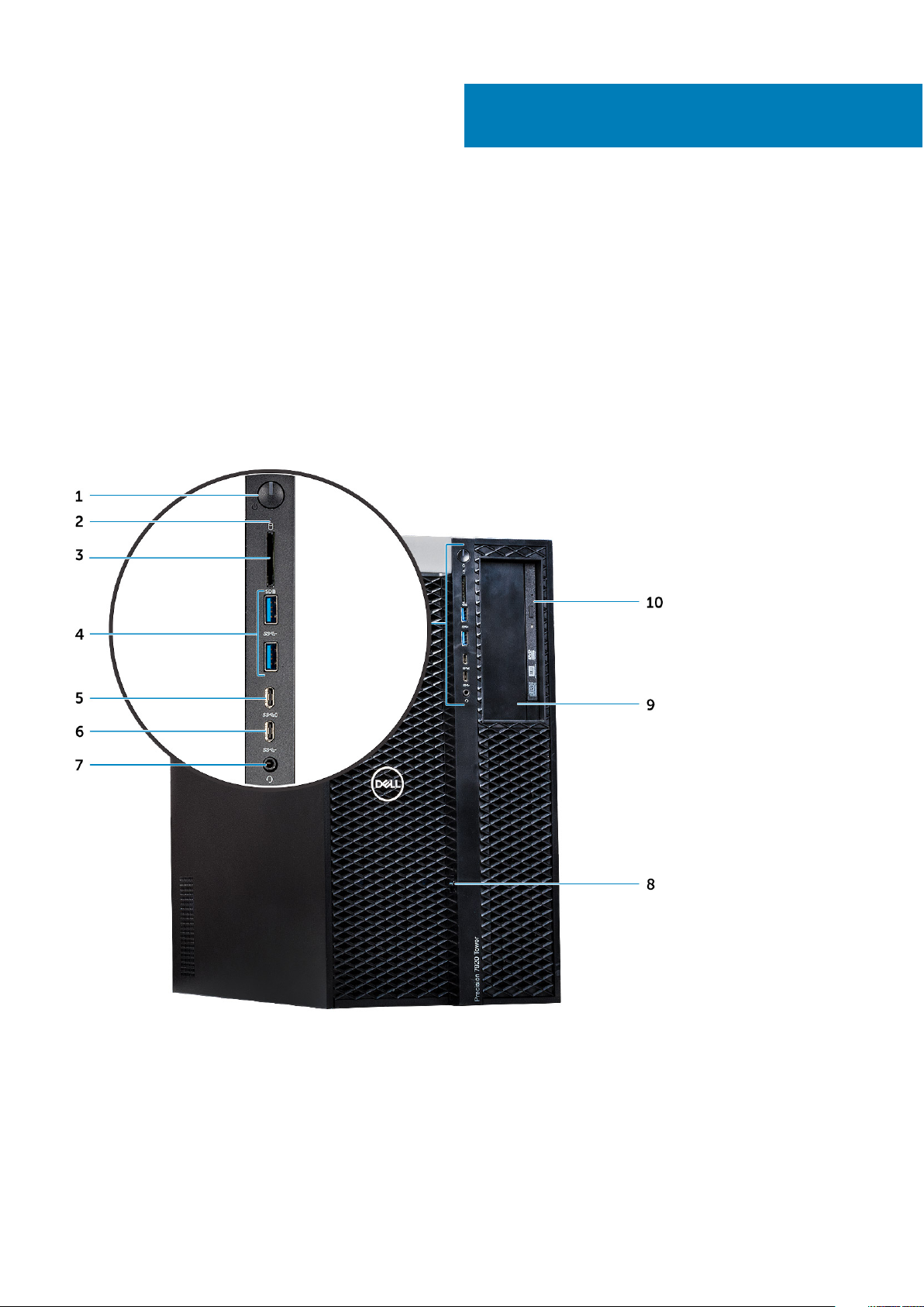
Front view
1
1. Power button/Power light 2. HDD Activity LED
3. SD card slot 4. USB 3.1 Gen 1 ports
5. USB 3.1 Gen 1 Type-C port with PowerShare 6. USB 3.1 Gen 1 Type-C port
7. Universal audio jack 8. Front bezel release latch
9. 5.25" ODD Bay 10. Slimline optical bay
Chassis 7
Page 8
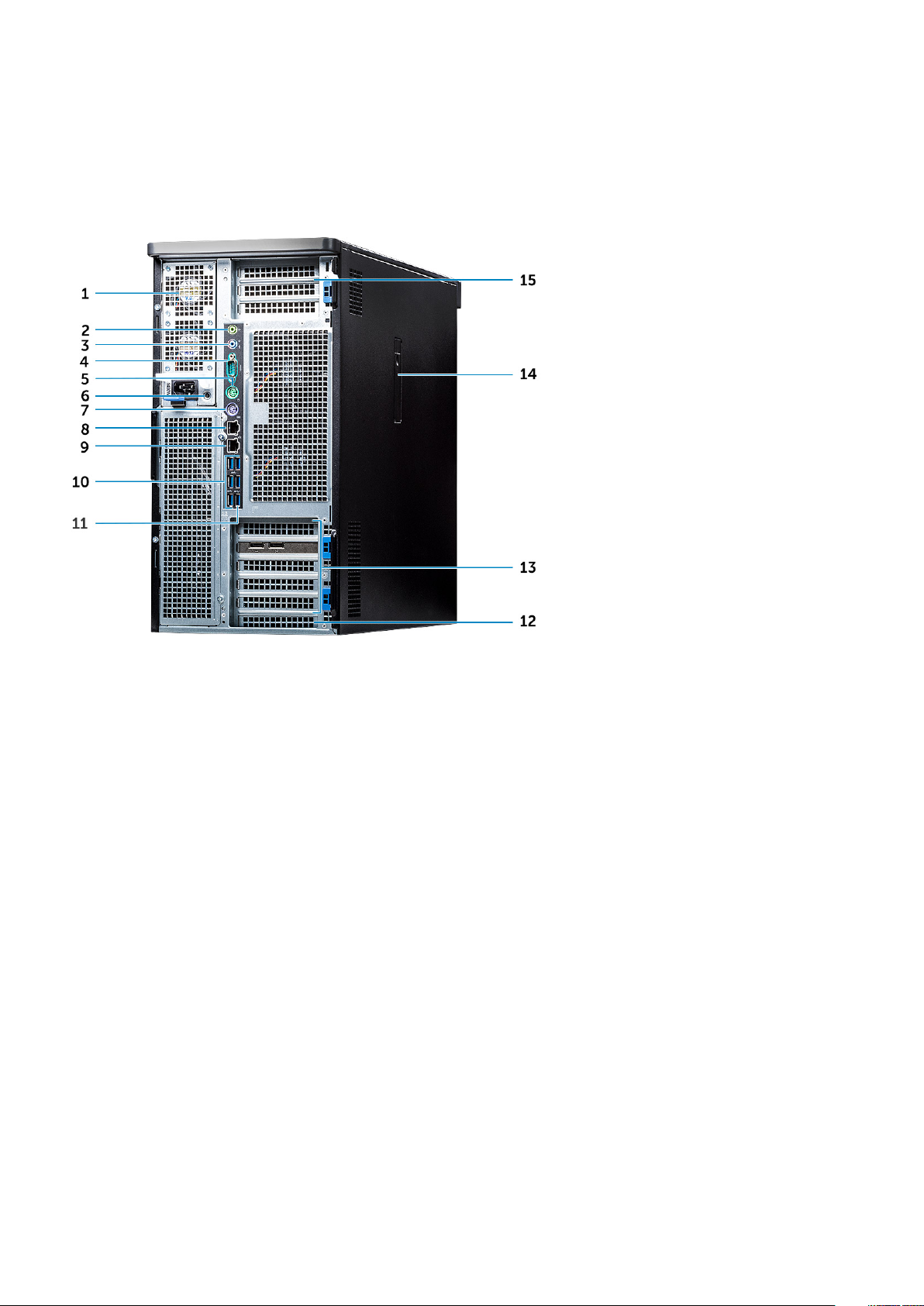
Back view
1. Power supply unit 2. Line-out port
3. Microphone/Line-in port 4. Serial port
5. PS/2 Mouse port 6. PSU BIST LED
7. PS/2 Keyboard port 8. Network Port (AMT Enabled - Optional)
9. Network Port 10. USB 3.1 Gen 1 ports
11. USB 3.1 Gen 1 Type-C port with PowerShare 12. Mechanical expansion slot
13. PCIe expansion slots 14. Side cover release latch
15. PCIe expansion slots (CPU1 required)
8 Chassis
Page 9
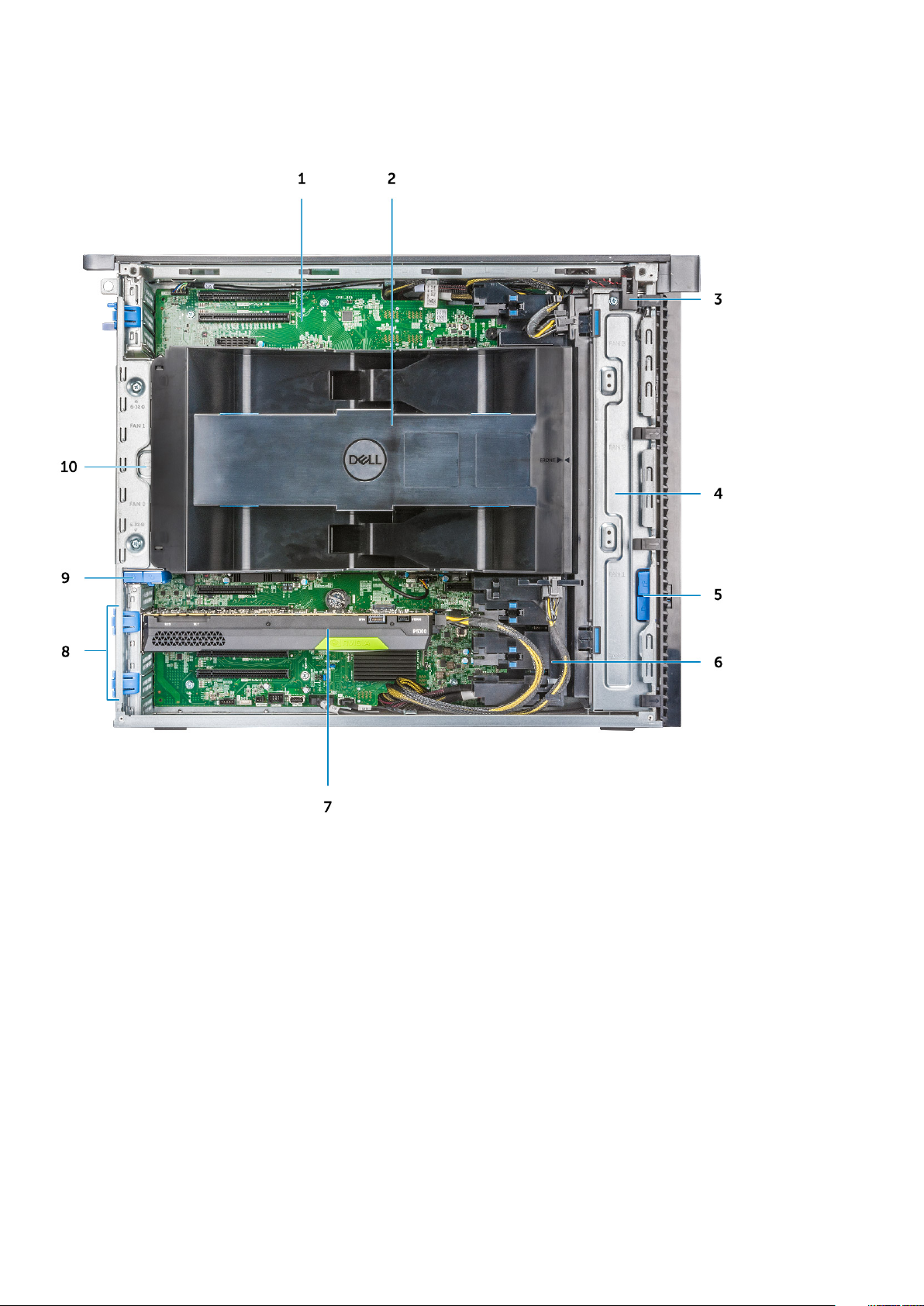
Internal view
1. System board 2. CPU and Memory Air shroud
3. Intrusion switch 4. Front system fan assembly
5. Front Bezel lock/unlock button 6. Auxiliary PCIe power cables
7. Powered graphical processing unit (GPU) 8. PCIe release latches
9. Rear HDD Bezel lock/unlock button 10. Rear Fans
Chassis 9
Page 10
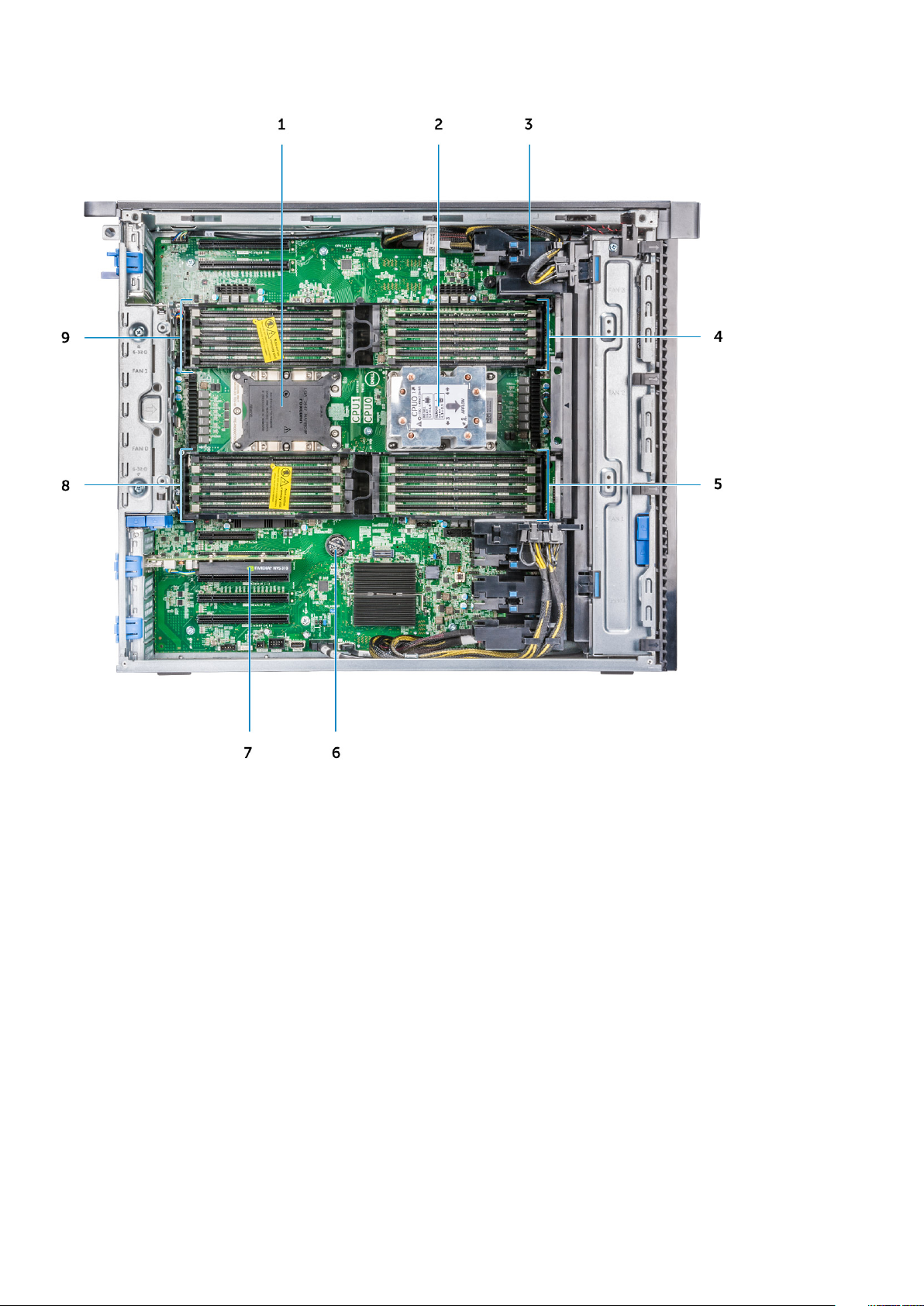
1. CPU1 socket 2. CPU0 Heatsink
3. PCIe holder 4. CPU0 Memory Slots
5. CPU0 Memory Slots 6. Coin cell battery
7. Half length PCIe graphics card 8. CPU1 Memory Slots
9. CPU1 Memory Slots
10 Chassis
Page 11
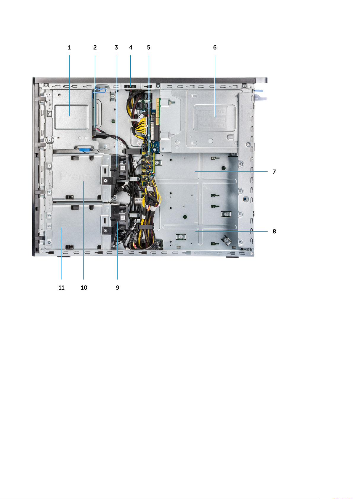
1. Flex 2 (default is 5.25" and Slim ODD Bay) 2. Data cable and power cable for the Slim ODD
3. HDD fan bracket 1 4. Intrusion switch
5. Power distribution and fan control board 6. PSU
7. Flex 3 (optional) 8. Flex 4 (optional)
9. HDD fan bracket 0 10. Flex 1 enclosure
11. Flex 0 enclosure
Chassis 11
Page 12
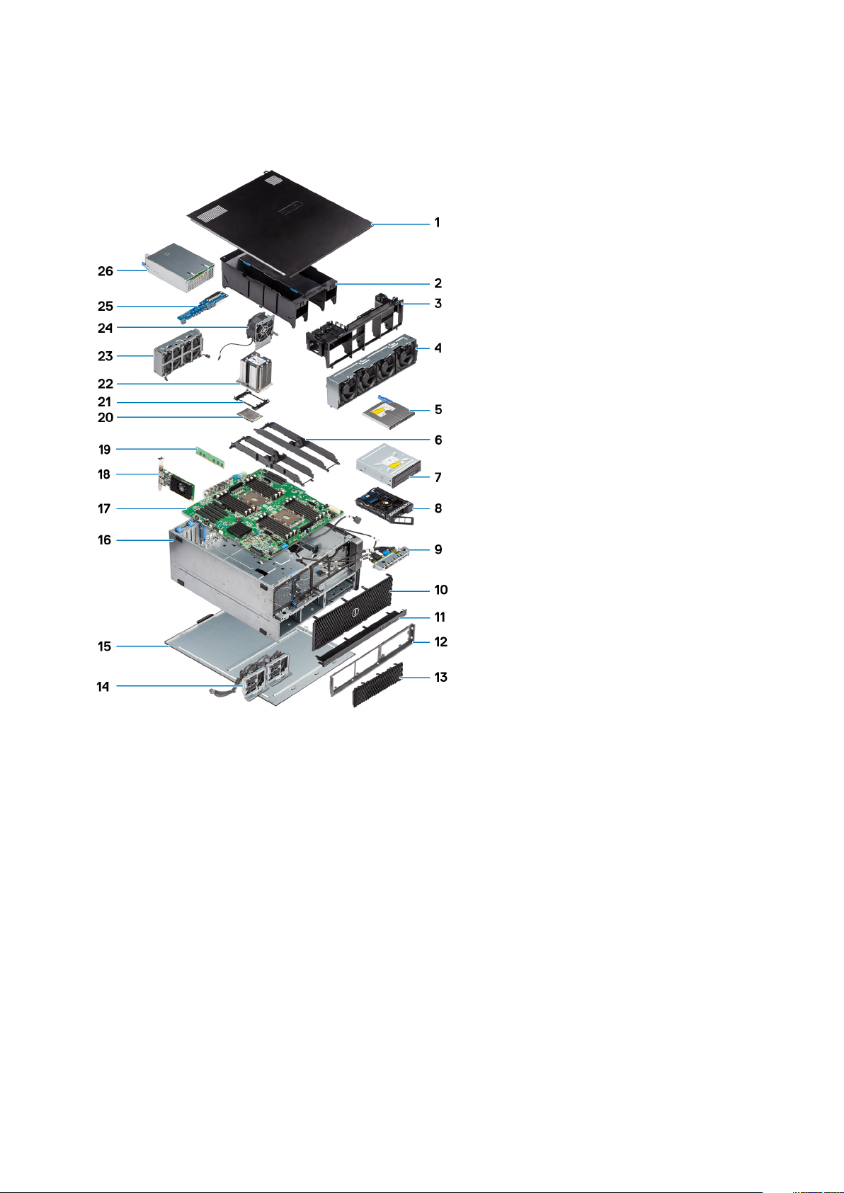
Major components of your system
This section illustrates the major components of your system along with its location.
1. Side cover
2. Air shroud
3. PCIe holder
4. Front system fan assembly
5. Slim Optical Disk Drive
6. Memory bracket
7. 5.25 inch Optical Disk Drive
8. NVMe Flexbay
9. Front input and output panel
10. Front bezel
11. Front input and output bezel
12. Hard disk drive and optical disk drive frame
13. Hard Disk Drive bezel
14. Backpane and Drop cables
15. Right side cover
16. Computer chassis
17. System board
18. Expansion card
19. Memory
20. Processor
21. CPU locking clip
12
Chassis
Page 13

22. Processor heat sink module
23. Front System fan
24. System fan
25. Power Distribution Board
26. Power supply unit (PSU)
NOTE: Dell provides a list of components and their part numbers for the original system configuration purchased. These
parts are available according to warranty coverages purchased by the customer. Contact your Dell sales representative for
purchase options.
Chassis 13
Page 14
2
Working on your computer
Topics:
• Safety instructions
• Turning off your computer — Windows
• Before working inside your computer
• After working inside your computer
Safety instructions
Use the following safety guidelines to protect your computer from potential damage and to ensure your personal safety. Unless
otherwise noted, each procedure included in this document assumes that the following conditions exist:
● You have read the safety information that shipped with your computer.
● A component can be replaced or, if purchased separately, installed by performing the removal procedure in reverse order.
NOTE: Disconnect all power sources before opening the computer cover or panels. After you finish working inside the
computer, replace all covers, panels, and screws before connecting to the power source.
WARNING: Before working inside your computer, read the safety information that shipped with your computer.
For additional safety best practices information, see the Regulatory Compliance Homepage
CAUTION: Many repairs may only be done by a certified service technician. You should only perform
troubleshooting and simple repairs as authorized in your product documentation, or as directed by the online or
telephone service and support team. Damage due to servicing that is not authorized by Dell is not covered by
your warranty. Read and follow the safety instructions that came with the product.
CAUTION: To avoid electrostatic discharge, ground yourself by using a wrist grounding strap or by periodically
touching an unpainted metal surface at the same time as touching a connector on the back of the computer.
CAUTION: Handle components and cards with care. Do not touch the components or contacts on a card. Hold a
card by its edges or by its metal mounting bracket. Hold a component such as a processor by its edges, not by
its pins.
CAUTION: When you disconnect a cable, pull on its connector or on its pull-tab, not on the cable itself. Some
cables have connectors with locking tabs; if you are disconnecting this type of cable, press in on the locking
tabs before you disconnect the cable. As you pull connectors apart, keep them evenly aligned to avoid bending
any connector pins. Also, before you connect a cable, ensure that both connectors are correctly oriented and
aligned.
NOTE: The color of your computer and certain components may appear differently than shown in this document.
CAUTION: System will shut down if side covers are removed while the system is running. The system will not
power on if the side cover is removed.
Turning off your computer — Windows
CAUTION:
computer or remove the side cover.
1. Click or tap .
14 Working on your computer
To avoid losing data, save and close all open files and exit all open programs before you turn off your
Page 15

2. Click or tap and then click or tap Shut down.
NOTE: Ensure that the computer and all attached devices are turned off. If your computer and attached devices did not
automatically turn off when you shut down your operating system, press and hold the power button for about 6 seconds
to turn them off.
Before working inside your computer
To avoid damaging your computer, perform the following steps before you begin working inside the computer.
1. Ensure that you follow the Safety Instruction.
2. Ensure that your work surface is flat and clean to prevent the computer cover from being scratched.
3. Turn off your computer.
4. Disconnect all network cables from the computer.
CAUTION: To disconnect a network cable, first unplug the cable from your computer and then unplug the
cable from the network device.
5. Disconnect your computer and all attached devices from their electrical outlets.
6. Press and hold the power button while the computer is unplugged to ground the system board.
NOTE: To avoid electrostatic discharge, ground yourself by using a wrist grounding strap or by periodically touching an
unpainted metal surface at the same time as touching a connector on the back of the computer.
After working inside your computer
After you complete any replacement procedure, ensure that you connect any external devices, cards, and cables before turning
on your computer.
1. Connect any telephone or network cables to your computer.
CAUTION:
computer.
2. Connect your computer and all attached devices to their electrical outlets.
3. Turn on your computer.
4. If required, verify that the computer works correctly by running ePSA diagnostics.
To connect a network cable, first plug the cable into the network device and then plug it into the
Working on your computer
15
Page 16

Removing and installing components
Topics:
• Screw size list
• Recommended tools
• Power supply unit (PSU)
• Side cover
• Air shroud
• Front bezel
• PCIe holder
• Intrusion switch
• Front system fan assembly
• Internal chassis speaker
• Hard disk drive and the Optical disk drive bezel
• Hard disk drive assembly
• NVMe Flexbay
• Front input and output bezel
• Front input and output panel
• Rear system fan
• Right side cover
• Hard disk drive and optical disk drive frame
• Slim Optical Disk Drive
• 5.25-inch optical drive
• Power distribution and fan control board
• Front HDD cable and fan assembly
• Fan bracket
• Graphical processing unit(GPU)
• Memory
• Coin cell battery
• Processor heat sink module
• System board
• RAID controller battery
• RAID controller battery bracket
• VROC module
3
Screw size list
Table 1. Screw list
Component Screw Type Quantity
PSU extended card #6-32X1/4 inches 3
FIO board #6-32X1/4 inches 2
Slim ODD cable for blind mate M3X5.0mm 2
Slim ODD cable for blind mate with ODD
bracket
FIO bracket #6-32X1/4 inches 1
Right Side Cover #6-32 UNC X7.0mm 2
16 Removing and installing components
#6-32 UNC X5.45mm 1
Page 17

Table 1. Screw list (continued)
Component Screw Type Quantity
Up-Bottom air shroud M3X5.0mm 3
Down-Bottom air shroud M3X5.0mm 2
Motherboard #6-32X1/4 inches 12
Front Fan Bracket-MB tray #6-32X1/4 inches 2
Front Fan Bracket-Front wall #6-32X1/4 inches 2
Intruder holder #6-32X1/4 inches 1
Rear Fan bracket #6-32X1/4 inches 2
Rear HDD cover #6-32 UNC X7.0mm 2
Flex0 HDD bay bracket #6-32 UNC X5.45mm 4
Flex0 6025fan bracket for cable
attached
Flex0 6025fan bracket for hot plug #6-32 UNC X5.45mm 2
Flex0 and Flex1 HH ODD bracket #6-32 UNC X5.45mm 4
Flex1 HDD bay bracket #6-32 UNC X5.45mm 4
Flex1 6025fan bracket for cable attached #6-32 UNC X5.45mm 2
Flex1 6025fan bracket for hot plug #6-32 UNC X5.45mm 2
Flex2 HDD bay bracket #6-32 UNC X5.45mm 4
Flex2 6025fan bracket for cable
attached
Flex3 HDD bracket #6-32 UNC X5.45mm 4
Flex3 6025fan bracket for cable
attached
Flex4 HDD bracket #6-32 UNC X5.45mm 4
Flex4 6025fan bracket for cable
attached
HH ODD holder M3X5.0mm 4
HSBP board #6-32 UNC X5.45mm 3
#6-32 UNC X5.45mm 2
#6-32 UNC X5.45mm 2
#6-32 UNC X5.45mm 2
#6-32 UNC X5.45mm 2
CPU0 cooler/CPU0 Liquid Cooler T-30 torx bolt 4
CPU1 cooler/CPU1 Liquid Cooler T-30 torx bolt 4
Liquid Cooler Bracket #6-32 UNC X5.45mm 12
Recommended tools
The procedures in this document require the following tools:
● Phillips #0 screwdriver
● Phillips #1 screwdriver
● Philips #2 screwdriver
● Plastic scribe
● T-30 torx screwdriver
NOTE: The #0 screw driver is for screws 0-1 and the #1 screw driver is for screws 2-4.
Removing and installing components 17
Page 18
Power supply unit (PSU)
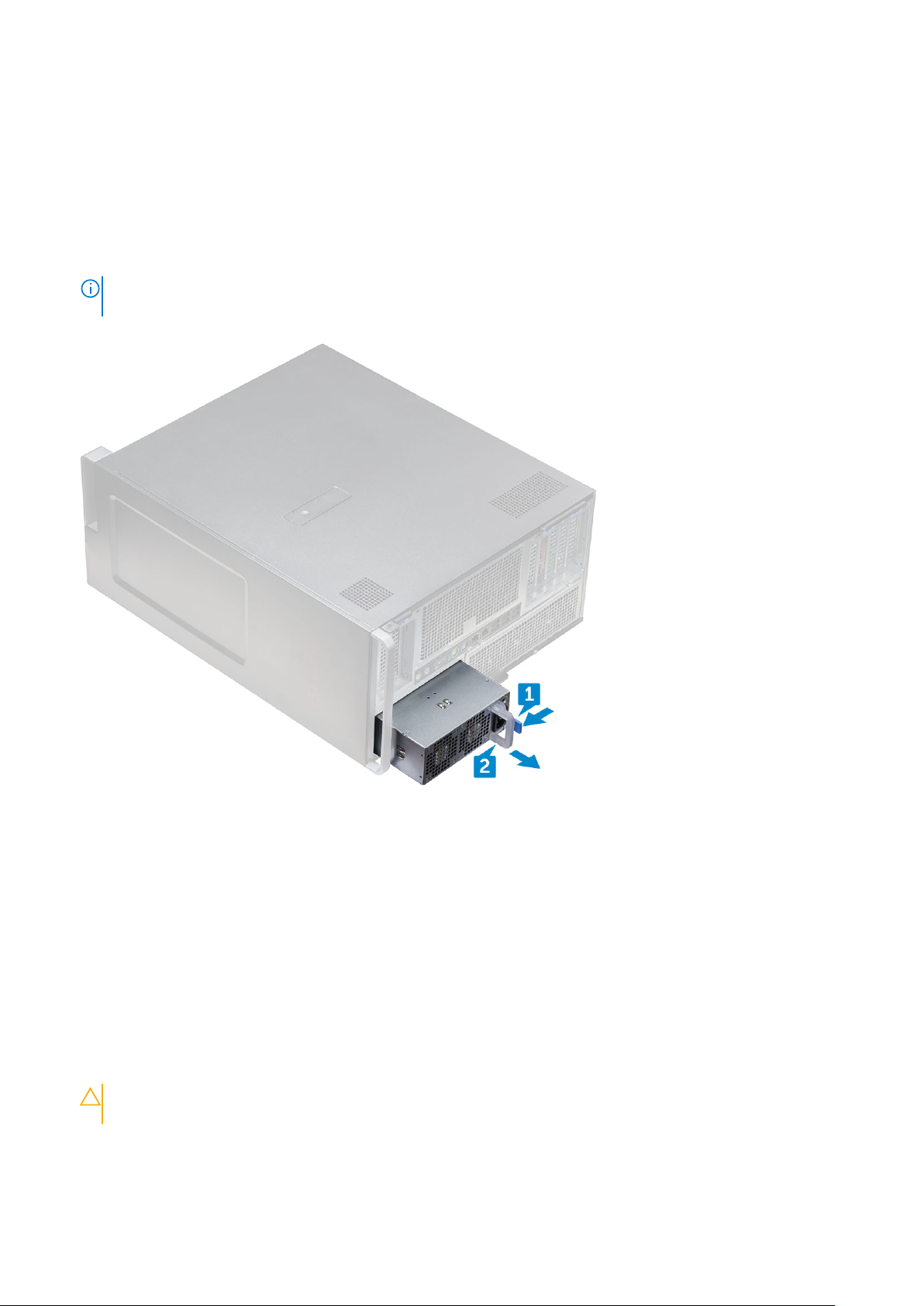
Removing the PSU
1. Follow the procedure in Before working inside your computer.
2. Disconnect the power cable from the system.
3. Press the PSU release latch [1] and slide the power supply away from the system [2].
NOTE: If the PSU cannot be removed then remove the right side cover of the system and check if the PSU is secured
with a screw.
Installing the PSU
1. Slide in the power supply unit to the PSU slot on the system.
2. Connect the power cable to the system.
3. Follow the procedure in After working inside your computer
Side cover
Removing the side cover
1. Follow the procedure in Before working inside your computer.
CAUTION:
side cover is removed while the system is on.
2. To remove the side cover:
3. Press the latch
18
Removing and installing components
The system will not power on while the side cover is off. Also, the system will shut down if the
Page 19
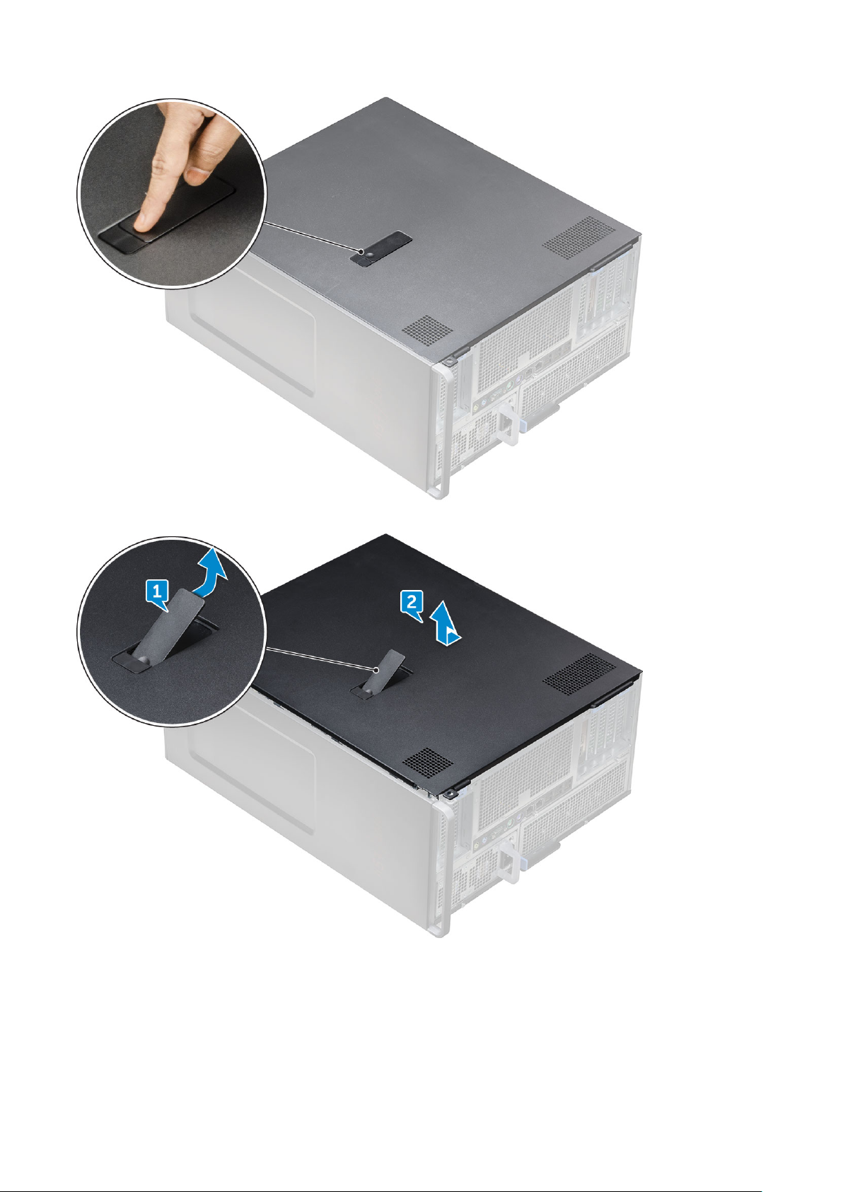
4. Pull the latch [1] upward and rotate it to release the cover [2].
5. Lift the cover to remove it from the system.
Installing the side cover
1. First hold and align the bottom of the side cover to the chassis.
2. Ensure that the hook on the bottom of the side cover snaps into the notch on the system.
3. Press the system cover until it clicks into place.
Removing and installing components
19
Page 20
CAUTION: The system will not power on without the side cover. Also, the system will shut down if the side
cover is removed while the system is on.
4. Follow the procedure in After working inside your computer .
Air shroud
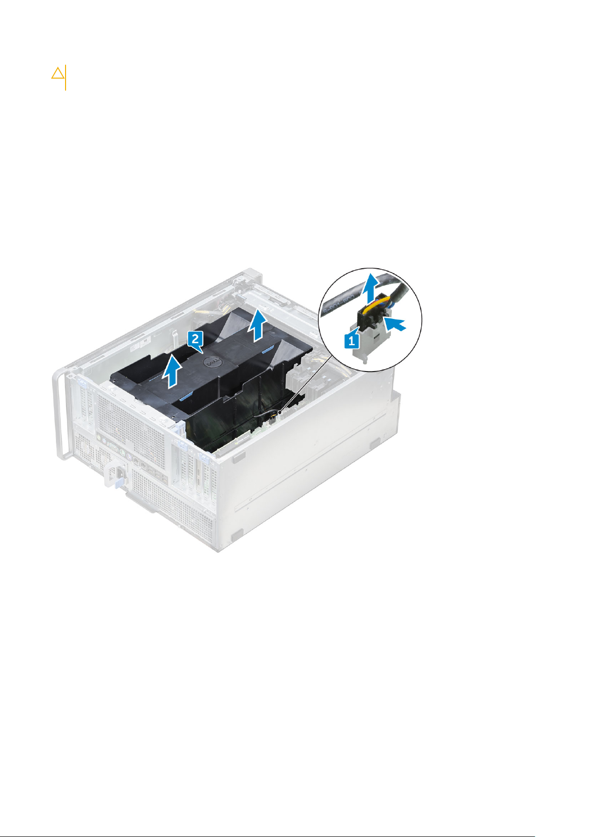
Removing the air shroud
1. Follow the procedure in Before working inside your computer.
2. Remove the side cover.
3. To remove the air shroud Fan assembly:
a. Disconnect the fan connector cable from the system board [1].
b. Lift the shroud away from the system [2].
Installing the air shroud fan assembly
1. Place the shroud into its position and ensure that the tab fits into the system.
2. Press down the shroud until it locks with a click.
3. Reconnect the fan connector cable to the system board.
4. Install the side cover.
5. Follow the procedure in After working inside your computer.
Removing the air shroud fan
1. Follow the procedure in Before working inside your computer.
2. Remove the:
a. side cover
20
Removing and installing components
Page 21
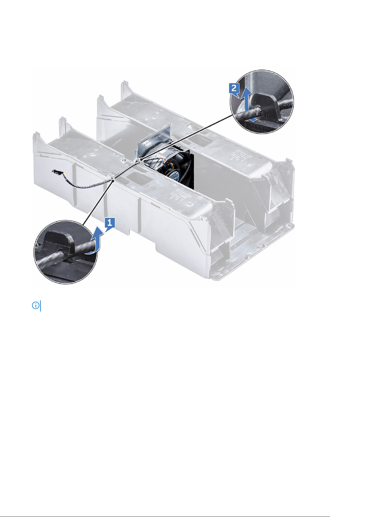
b. removing air shroud (Top)
3. Flip-over the shroud to see the fan.
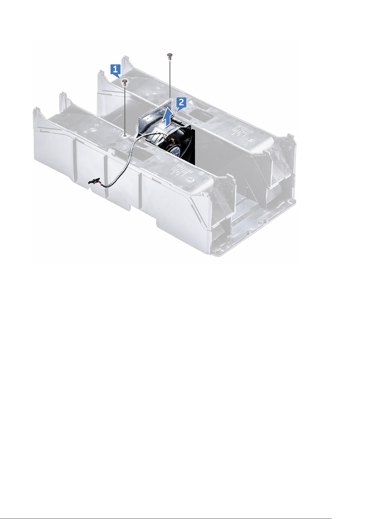
4. To remove the fan, release the fan connector cable from the latches [1] and [2].
5. Remove the screws that secures the fan to the air shroud [1], and lift the fan away from the air shroud [2].
NOTE: The shroud will need to be flexed open slightly in order to be removed.
Removing and installing components 21
Page 22
Installing the air shroud fan
1. Place the fan into its position inside the air shroud .
2. Replace the screws that secure the fan to the air shroud.
3. Route back the fan connector cable through the latches on the air shroud and flip over.
4. Install the:
a. air shroud (top)
b. side cover
5. Follow the procedure in After working inside your computer.
Front bezel
Removing the front bezel
1. Follow the procedure in Before working inside your computer.
2. Remove the side cover.
3. To remove the front bezel:
a. Press the latch and pry the retention tabs to release the front bezel from the system.
22
Removing and installing components
Page 23
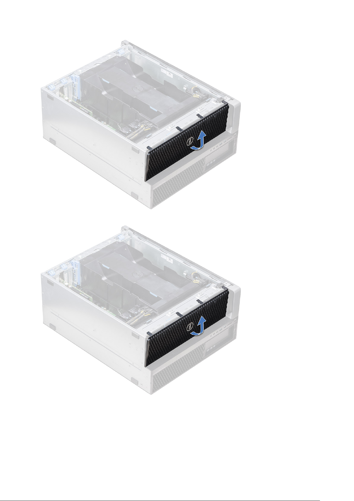
b. Rotate the bezel forward and lift the front bezel away from the system.
Installing the front bezel
1. Hold the bezel and ensure that the hooks on the bezel snap into the notches on the system.
2. Rotate the bezel forward and press the front bezel until the tabs click into place.
3. Follow the procedure in After working inside your computer.
Removing and installing components
23
Page 24
PCIe holder
Removing PCIe card holder
1. Follow the procedure in Before working inside your computer.
2. Remove the following:
a. side cover
b. air shroud
3. To remove the PCIe card holder:
NOTE: If full length cards are installed, you will need to remove these cards before removing the holder.
NOTE: If MegaRAID 9460 is installed, disconnect the Super CAP from the card before removing the PCIe card holder
from the system.
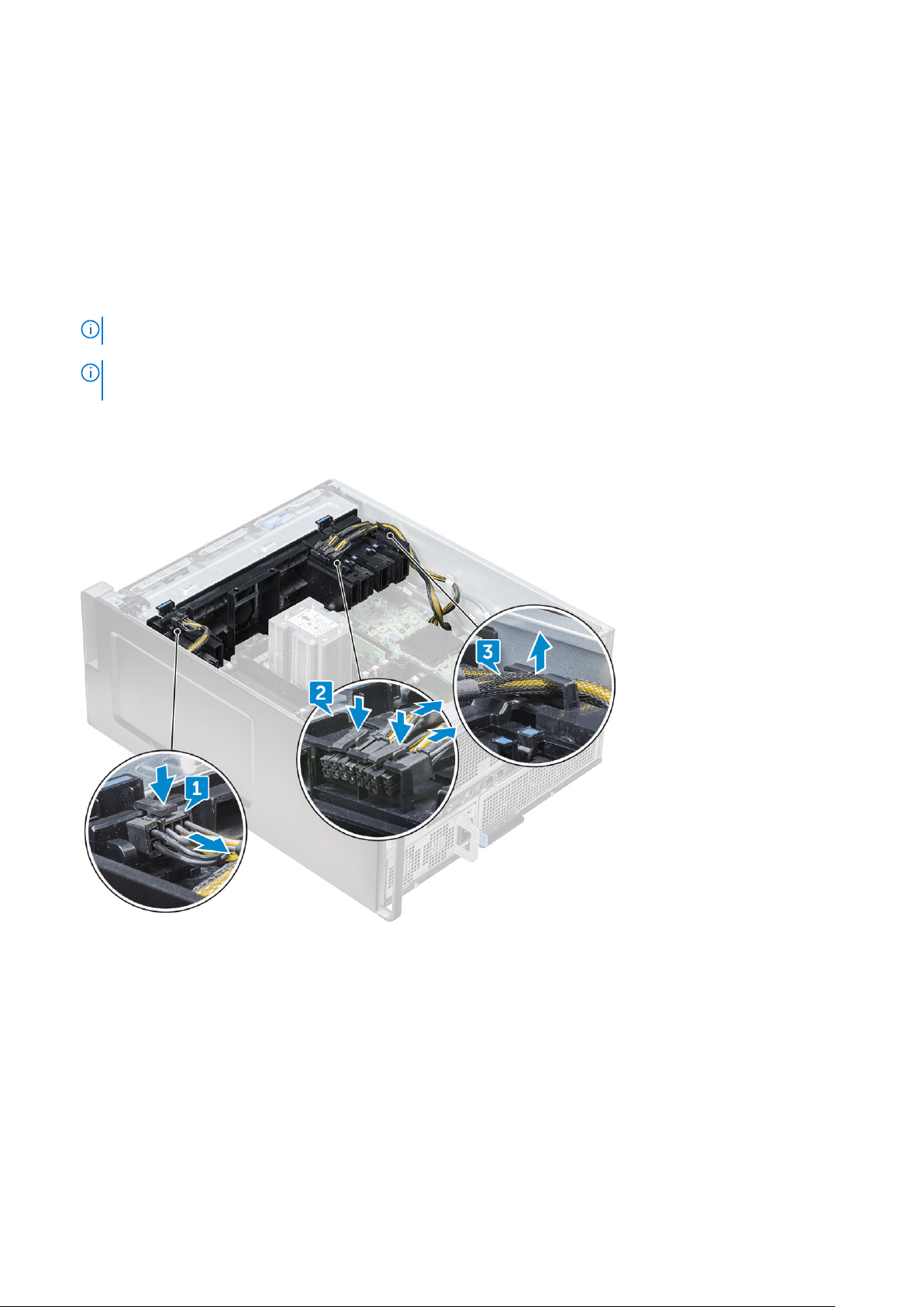
a. Disconnect the power cables on either side of the card holder by pressing the tab and pulling it out of the cable slot in
the PCIe holder [1] and [2].
b. Release the dual cables passing through the clip on the card holder [3].
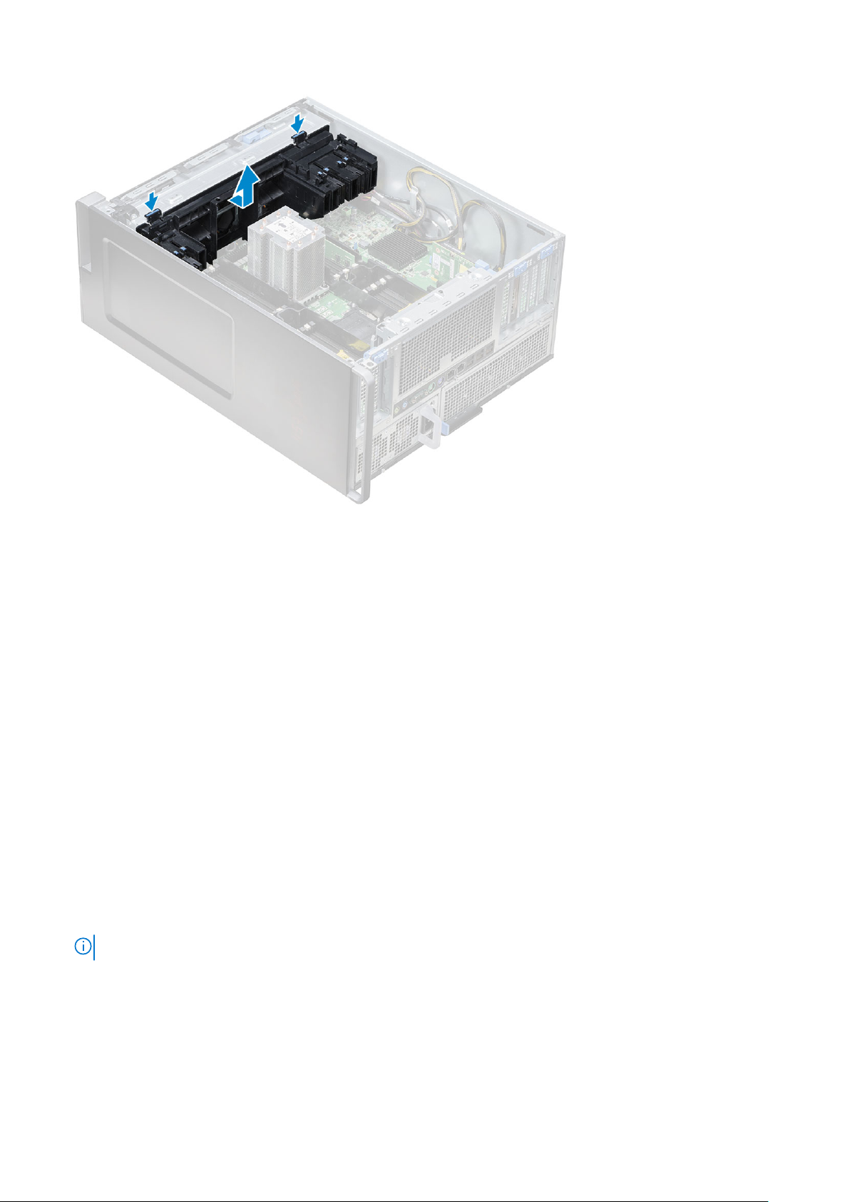
4. Release the latches connecting the front system fan assembly, and lift the PCIe card holder away from the chassis.
24
Removing and installing components
Page 25
Installing the PCIe card holder
1. Align the PCIe card holder to the slot in front of the system fan assembly, and press down until it clicks in place.
2. Route the dual cables back through the clip on the PCIe card holder.
3. Connect the power cables on either side to the cable slots in the PCIe card holder.
4. Reinstall the full length cards if they were removed.
5. If the MegaRAID 9460 was removed, please connect the Super CAP back to the card.
6. Install the:
a. air shroud
b. side cover
7. Follow the procedure in After working inside your computer.
Intrusion switch
Removing the intrusion switch
1. Follow procedure in Before working inside your computer.
2. Remove the right side cover.
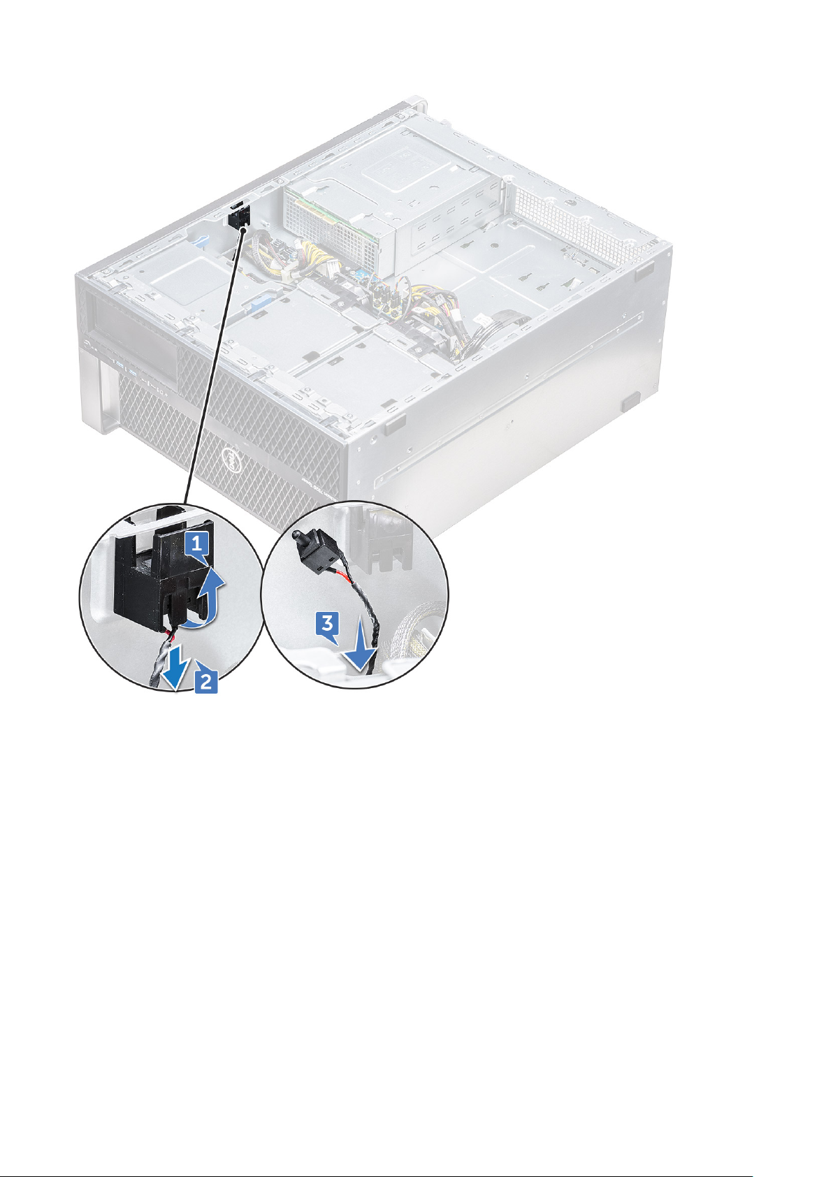
3. To remove the intrusion switch that is located at the bottom of the system board:
NOTE: The system will not power on when the intrusion switch is uninstalled.
a. Press the knob of the intrusion switch toward the bottom of the chassis [1, 2].
b. Pull the intrusion switch down to remove it from the slot [3].
Removing and installing components
25
Page 26
4. Install the right side cover
5. Flip the system back with the system cover facing up where the release latch is available.
6. Remove the following components :
a. side cover
b. air shroud
c. PCIe card holder
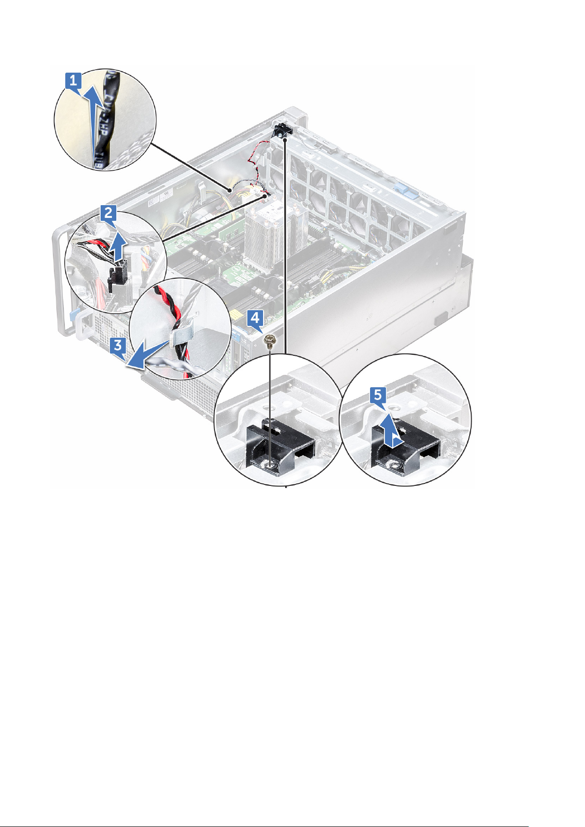
7. To remove the intrusion switch module:
a. Pull the bottom intrusion switch cable up toward the chassis [1].
b. Press the tab to disconnect the intrusion switch cable from the system board [2].
c. Unroute the intrusion switch cables from the clip on the chassis [3].
d. Remove the screw on the intrusion module [4].
e. Lift the intrusion module from the front system fan assembly [5].
26
Removing and installing components
Page 27
Installing the intrusion switch
1. Place the intrusion switch module into the slot in the front system fan assembly.
2. To secure the intrusion switch module to the front system fan chassis, replace the single screw on the module.
3. Route the intrusion switch cables through the clip on the chassis.
4. Connect the intrusion switch cable to the system board.
5. Push the bottom intrusion switch cable down toward the bottom chassis.
6. Replace the following components:
a. PCIe graphics card holder
b. air shroud
c. side cover
7. Remove the right side cover.
8. Pull the intrusion switch cable up from the top chassis.
9. Insert and slide the intrusion switch into the slot in the chassis to secure it.
10. Follow the procedure in After working inside your computer.
Removing and installing components
27
Page 28
Front system fan assembly
Removing the front system fan assembly
1. Follow the procedure in Before working inside your computer.
2. Remove the following:
a. side cover
b. front bezel
c. air shroud
d. PCIe card holder
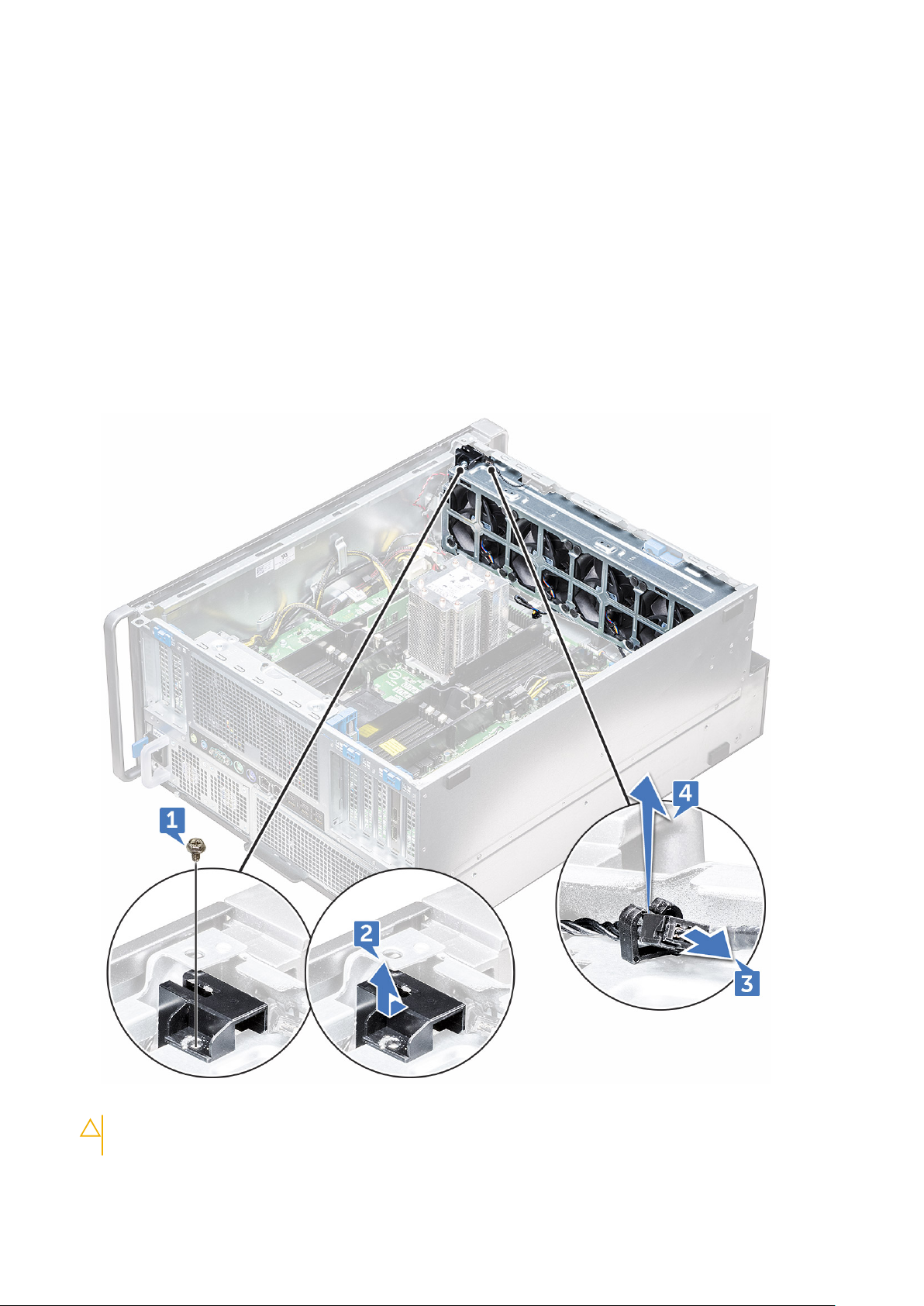
3. To remove the system fan assembly:
a. Remove the single screw on the intrusion switch module [1], and lift it away from the system fan chassis [2].
b. Disconnect the internal chassis speaker cable from the connector, unroute it from the clip on the system fan chassis [3],
and lift it away from chassis [4].
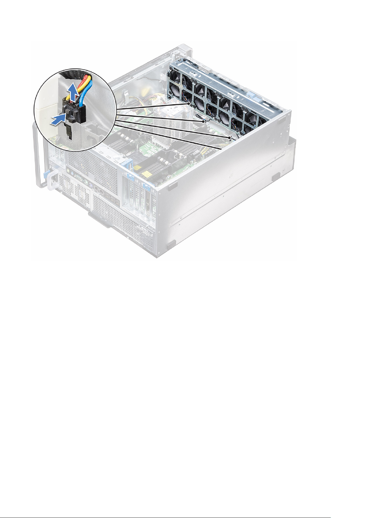
4. Disconnect the four system fan cables from the connectors on the system board.
CAUTION:
connector end. Pulling the cable wires may loosen them from the connector.
28 Removing and installing components
Do not pull the connector by the cable wires. Instead, disconnect the cable by pulling on the
Page 29
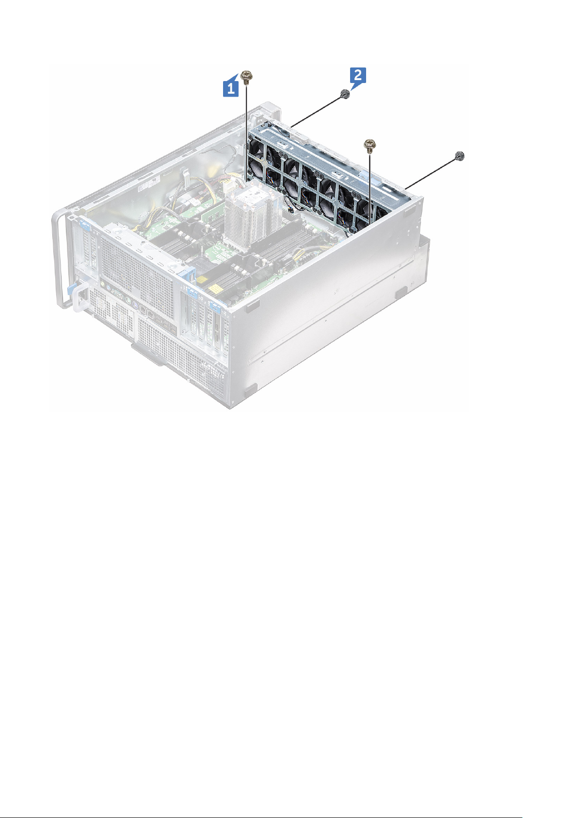
5. Remove the two screws securing the fan chassis to the system [1], and the two screws securing the fan chassis in front of
the system [2].
Removing and installing components
29
Page 30
6. Rotate and lift the fan assembly away from the system.
30
Removing and installing components
Page 31

Installing the front system fan assembly
1. Hold the system fan by the sides with the cable end facing the bottom of the chassis.
2. Replace the two screws securing the system fan assembly in front of the system.
3. Replace the two screws securing the system fan assembly in the system.
4. Connect the four system fan cables to the system board.
5. Route back the internal chassis speaker cable through the clip on the system fan assembly, and connect the internal chassis
speaker to the connector.
6. Replace the intrusion switch module to the slot on the fan assembly and insert the screw to secure it with the system fan
assembly.
7. Install the following components:
a. PCIe graphics card holder
b. air shroud
c. front bezel
d. side cover
8. Follow the procedure in After working inside your computer.
Internal chassis speaker
Removing the internal chassis speaker
1. Follow the procedure in Before working inside your computer.
2. Remove the following:
Removing and installing components
31
Page 32

a. side cover
b. front bezel
3. To remove the internal chassis speaker:
a. Disconnect one end of the internal chassis speaker cable from the connector on the system fan assembly [1].
b. Unroute the internal chassis speaker cable from the clip on the system fan assembly.
4. Press and hold the tabs [2] on either side of the internal chassis speaker, to slide and remove it out of the system [3].
Installing the internal chassis speaker
1. Press and hold the tabs on either side of the internal chassis speaker, and slide the speaker module into the slot to secure it
to the system.
2. Route the internal chassis speaker cable through the clip on the system fan assembly.
3. Connect the one end of the internal chassis speaker cable to the connector on the system fan assembly.
4. Install the following components:
a. air shroud
b. front bezel
c. side cover
5. Follow the procedure in After working inside your computer
32
Removing and installing components
Page 33

Hard disk drive and the Optical disk drive bezel
Removing the HDD bezel
1. Follow the procedure in Before working inside your computer.
2. Remove the following components:
a. side cover
b. front bezel
3. To remove the HDD bezel:
a. Press the blue unlock button [1], which is located near the front system fan assembly.
b. Slide the latch [2] on the front I/O bezel, to release the HDD bezel from the chassis [3].
c. Rotate and lift the HDD bezel out from the chassis [3].
4. Optional: Remove the ODD bezel from the chassis by prying the edges of the bezel and lift it away.
Installing the HDD bezel
1. If the ODD bezel is removed, install it by aligning the notch of the bezel into the slot on the chassis (Optional).
2. Align the HDD bezel onto its slots on the chassis and press the HDD bezel towards the chassis.
3. Press the blue lock button located near the front system fan assembly, to secure the HDD bezel to the chassis.
4. Install the following components:
a. front bezel
b. side cover
5. Follow the procedure in After working inside your computer
Removing and installing components
33
Page 34

Hard disk drive assembly
Removing the HDD carrier
1. Follow the procedure in Before working inside your computer.
2. Remove the:
a. side cover
NOTE: Do not remove the side cover, if the front I/O bezel is unlocked.
b. HDD bezel
NOTE: Remove only the HDD bezel.
3. To remove the HDD carrier:
a. Press the release button [1] to unlock the latch [2].
b. Pull the latch to slide the carrier out of the HDD slot.
34
Removing and installing components
Page 35

Installing the HDD carrier
1. Slide the carrier into the drive bay until it clicks into place.
CAUTION: Ensure that the latch is open before installing the carrier.
2. Lock the latch.
3. Install the following components:
a. HDD bezel
b. side cover
4. Follow the procedure in After working inside your computer.
Removing the HDD
1. Follow the procedure in Before working inside your computer.
2. Remove the following:
a. side cover
b. HDD bezel
c. HDD carrier
3. To remove the 3.5 inch HDD:
a. Expand one side of the carrier.
Removing and installing components
35
Page 36

b. Lift the hard drive out of the carrier.
Installing the HDD
1. Insert the HDD to its slot in the HDD bracket with the connector end of the hard drive towards the back of the HDD carrier.
2. Slide the HDD carrier back into the hard drive bay.
3. Install the following:
a. HDD carrier
36
Removing and installing components
Page 37

b. HDD bezel
c. side cover
4. Follow the procedure in After working inside your computer
NVMe Flexbay
Removing the NVMe Flexbay
1. Follow the procedure in Before working inside your computer.
2. Remove the:
a. side cover
NOTE: Do not remove the side cover, if the front I/O bezel is unlocked.
b. HDD bezel
NOTE: Remove only the HDD bezel.
3. To remove the NVMe flexbay:
a. Press the release button [1] to unlock the latch [2].
b. Pull the latch to slide the carrier out of the HDD slot.
Removing and installing components
37
Page 38

4. To remove the SSD carrier from the NVMe flexbay:
a. Press the release button to slide the M.2 SSD carrier out of the NVMe flexbay.
b. Pull the M.2 SSD carrier out of the NVMe flexbay.
38
Removing and installing components
Page 39

5. To remove the SSD from the SSD carrier:
a. Remove the screws on either side of the SSD.
b. Remove the screw from the top of the SSD carrier.
Removing and installing components
39
Page 40

c. Slide the SSD cover from the top of the carrier.
d. Slide the SSD out of the M.2 slot on the carrier.
40
Removing and installing components
Page 41

Installing the NVMe flexbay
1. To install the SSD in the carrier:
a. Remove the dummy SSD blank from the SSD carrier.
b. Peel off the tape from the SSD carrier.
Removing and installing components
41
Page 42

c. Peel off the adhesive tape from the SSD carrier cover.
2. Install the SSD in the carrier
42
Removing and installing components
Page 43

3. Replac the two side screws and the central screw.
4. To install the SSD carrier slide the carrier in the NVMe flexbay until it clicks in place.
5. Slide the carrier into the drive bay until it clicks into place.
CAUTION: Ensure that the latch is open before installing the carrier.
6. Lock the latch.
7. Install the following components:
a. HDD bezel
b. side cover
8. Follow the procedure in After working inside your computer.
Front input and output bezel
Removing the front input and output bezel
1. Follow the procedure in Before working inside the computer.
2. Remove the:
a. side cover
b. front bezel
c. HDD and ODD bezel
3. To remove the front Input/Output (I/O) bezel, pry the edges of the panel [1].
Removing and installing components
43
Page 44

4. Slightly slide the panel, and lift it away from the chassis.
44
Removing and installing components
Page 45

Installing the front input and output bezel
1. Align and press the bezel toward the front chassis on the system.
2. Install the:
a. HDD and ODD bezel
b. front bezel
c. side cover
3. Follow the procedure in After working inside your computer
Front input and output panel
Removing the front input and output panel
1. Follow the procedure in Before working inside your computer.
2. Remove the following:
a. side cover
b. air shroud
c. front bezel
d. PCIe holder
e. front system fan
f. HDD and ODD bezel
Removing and installing components
45
Page 46

g. input and output bezel
3. To remove the front Input/Output (I/O) panel:
a. Disconnect the following cables from the connectors on the I/O panel.
● Front panel cable [1]
● Front USB 3.1 cable [2]
● Front USB 3.1 cable [3]
● Front panel audio cable [4]
b. Remove the single screw that secures the I/O panel to the chassis.
46
Removing and installing components
Page 47

4. Slide the I/O panel toward the left of the system to release it, and then remove the I/O panel out of the system.
Removing and installing components
47
Page 48

Installing the front input and output panel
1. Insert the I/O panel into the slot on the front of the chassis.
2. Slide the I/O panel toward the right of the system to secure it to the chassis.
3. Replace the screw to secure the I/O panel to the chassis.
4. Connect the following cables to the connectors on the I/O panel:
● Front panel cable
● Front USB 3.1 cable
● Front USB 3.1 cable
● Front panel audio cable
NOTE: The color of the cable matches the color of the connector.
5. Install the following:
a. input and output bezel
b. HDD and ODD bezel
c. front system fan
d. PCIe holder
e. front bezel
48
Removing and installing components
Page 49

f. air shroud
g. side cover
6. Follow the procedure in After working inside your computer
Removing the input and output panel bracket
1. Follow the procedure in Before working inside your computer.
2. Remove the following:
a. side cover
b. air shroud
c. front bezel
d. PCIe holder
e. front system fan
f. HDD and ODD bezel
g. input and output bezel
h. input and output panel
3. To remove the Input/Output (I/O) panel bracket:
a. Remove the two screws that secure the I/O panel to the bracket.
b. Release and remove the I/O panel out of the bracket.
Removing and installing components
49
Page 50

Installing the input and output panel
1. Insert the Input/Output (I/O) panel into the metal bracket.
2. Replace the two screws to secure the I/O panel to the I/O bracket.
3. Install the:
a. input and output panel
b. input and output bezel
c. HDD bezel
d. front system fan
e. PCIe holder
f. front bezel
g. air shroud
h. side cover
4. Follow the procedure in After working inside your computer
Rear system fan
Removing the rear system fan
1. Follow the procedure in Before working inside your computer.
2. Remove the following:
a. side cover
b. air shroud
3. To remove the rear system fan assembly:
a. Remove the two screws [1], and press the tab [2] to rotate the rear system fan into the chassis and remove it from
holder.
50
Removing and installing components
Page 51

b. Disconnect the system fan cables from the system board [1, 2].
CAUTION:
connector end. Pulling on the cable wires may loosen them from the connector.
Do not pull the connector by the cable wires. Instead, disconnect the cable by pulling on the
4. Lift the system fan assembly from the system.
Removing and installing components
51
Page 52

Installing the rear system fan
1. Hold the rear system fan by the sides with the cable end facing the bottom of the chassis.
2. Connect the two system fan cables to the system board.
3. Replace the two screws to secure the fan with the chassis.
4. Install the:
a. air shroud
b. side cover
5. Follow the procedure in After working inside your computer.
Right side cover
Removing the right side cover
1. Follow the procedure in Before working inside your computer.
2. Place the system chassis on the side with the right side cover facing upward.
3. Remove the two screws [1], that secure the right side cover to the chassis.
4. Slide the side cover back with the handle, and then lift it away from the system [2].
Installing the right side cover
1. Slide the cover forward and ensure that the hooks on the cover snap into the notches on the system.
2. Replace the two screws that secure the right side of the cover to the chassis.
3. Follow the procedure in After working inside your computer.
52
Removing and installing components
Page 53

Hard disk drive and optical disk drive frame
Removing the HDD and ODD frame
1. Follow the procedure in Before working inside the computer.
2. Remove the:
a. side cover
b. front bezel
c. HDD and ODD bezel
d. front i/o bezel
3. To remove the front HDD and ODD frame, gently pry on the latches of the frame.
4. Slightly pull the panel, and lift it away from the chassis.
Removing and installing components
53
Page 54

5. Flip the frame.
6. Gently press the release tab on the plastic filler and lift it out of the frame.
54
Removing and installing components
Page 55

7. Holding the blue tag, gently pull the optical drive metal filler out of the slot.
Removing and installing components
55
Page 56

Installing the HDD and ODD frame
1. Install the plastic filler and metal blank if the optical drive is not installed.
2. Align and place the HDD and ODD frame on the system.
3. Gently press down on the frame to secure it to the system.
4. Install the:
a. front I/O bezel
b. HDD and ODD bezel
c. front bezel
d. side cover
5. Follow the procedure in After working inside your computer.
Slim Optical Disk Drive
Removing the slim ODD and ODD latch
1. Follow the procedure in Before working inside the computer.
2. Remove the right side cover
3. To remove the ODD:
a. Disconnect the data cable and power cable [1] from the optical drive connector.
b. Slide the blue latch towards the left of the chassis, and push the drive forward [2].
56
Removing and installing components
Page 57

4. Remove the ODD out of the drive bay.
5. To remove the ODD bracket from the ODD drive:
a. Push the optical drive latch inwards so that the latch disconnects from the optical drive.
Removing and installing components
57
Page 58

b. Remove the latch from the optical drive.
Installing the slim ODD and ODD latch
1. Place the ODD latch into its position on the ODD drive and lock it.
2. Slide the optical drive into the drive bay from the front of the system until it fits in to place.
3. Connect the data cable and power cable to the connectors on the optical drive.
4. Install the right side cover
5. Follow the procedure in After working inside your computer
58
Removing and installing components
Page 59

5.25-inch optical drive
Removing the 5.25-inch optical drive
1. Follow the procedure in Before working inside your computer.
2. Remove the:
a. side cover
3. To remove the 5.25-inch optical drive:
a. Disconnect the power cable and the SATA cable from the optical drive.
b. Push down on the release latch [1].
c. Slide the optical drive out of the system [2].
Removing and installing components
59
Page 60

Installing the 5.25-inch optical drive
1. Remove the:
a. side cover
b. front bezel
c. HDD and optical drive bezel
d. front I/O bezel
e. HDD and optical drive frame
2. Align the screw holes on the bracket with the holes on the optical drive.
3. Install the four screws that secure the plastic optical drive bracket to the optical drive.
60
Removing and installing components
Page 61

4. Slide the optical drive into the slot, until it locks into place.
5. Connect the power cable and the SATA cable to the optical drive.
6. Install the:
a. HDD and optical drive frame
b. front I/O bezel
c. HDD and optical drive bezel
d. front bezel
e. side cover
7. Follow the procedure in After working inside your computer.
Power distribution and fan control board
Removing the power distribution and fan control board
1. Follow the procedure in Before working inside the computer.
2. Remove the:
a. PSU
b. right side cover
3. To remove the power distribution and fan control board:
a. Press the tab on both sides of the connector and disconnect the power cable on the control board [1].
b. Disconnect the fan cables from the connectors on the control board [2].
c. Disconnect the power, PDB, and power VGA cables from the connectors on the control board [3].
Removing and installing components
61
Page 62

4. Remove the three screws that secure the control board to the chassis [1, 2]. Lift the control board away from the chassis.
Installing the power distribution and fan control board
1. Replace the control board into its slot on the chassis and secure it with the three screws to the chassis.
2. Connect the two power cables, fan cables, PDB, power VGA cables, to the connectors on the control board.
3. Install the:
a. right side cover
62
Removing and installing components
Page 63

b. PSU
4. Follow the procedure in After working inside your computer
Front HDD cable and fan assembly
Removing the front HDD cable and fan assembly
1. Follow the procedure in Before working inside the computer.
2. Remove the right side cover
3. To remove the front HDD cable and fan assembly:
a. Remove the four screws securing both the fan brackets to the chassis [1].
b. Press the tabs of the connector to disconnect the SATA 0 cable from the connector on the system board [2].
c. Press the tabs to disconnect the power cable and remove it from the plug [3].
d. Disconnect the fan cables from the connectors on the power distribution and fan control board [4].
CAUTION: Do not pull the connector by the cable wires. Instead, disconnect the cable by pulling on the
connector end. Pulling on the cable wires may loosen them from the connector.
4. Remove the HDD fan and cable assembly from the chassis.
Removing and installing components
63
Page 64

Installing the front HDD cable and fan assembly
1. Connect the fan cables to the connectors on the power distribution and fan control board.
2. Connect the power cable to the connector on the power distribution and fan control board.
3. Connect the SATA 0 cable to the connector on the system board.
4. Replace the front HDD cable and fan assembly into their slots on the chassis and secure them with screws to the chassis.
5. Install the right side cover
6. Follow the procedure in After working inside your computer
Fan and sensor cable assembly
Precision 7920 Tower may have as many as 12 system fans connected to the system board. It is important for technicians to
connect these fans to it's assigned connectors on the system board.
64
Removing and installing components
Page 65

Figure 1. Mandatory System Fan
Removing and installing components
65
Page 66

Figure 2. HDD Fans
NOTE: Availability of these fans are dependent on configuration ordered.
Table 2. Fan and Cable Description
Fan Cable Description Silk Screen Fan Installation Guide
CPU 1 Fan CPU 1 fan cable FAN_CPU1 Mandatory
Front System
Fans
Rear System
Fans
HDD Fans Fan in Flex0 FAN_FLEX0 Depend on shipped configuration
66 Removing and installing components
Fan0 cable FAN_SYS0 Mandatory
Fan1 cable FAN_SYS1 Mandatory
Fan2 cable FAN_SYS2 Mandatory
Fan3 cable FAN_SYS3 Mandatory
Fan0 cable FAN_REAR0 Mandatory
Fan1 cable FAN_REAR1 Mandatory
Fan in Flex1 FAN_FLEX1
Fan in Flex2 FAN_FLEX2
Fan in Flex3 FAN_FLEX3
Fan in Flex4 FAN_FLEX4
Page 67

Mandatory System Fan
Removing and installing components 67
Page 68

68 Removing and installing components
Page 69

NOTE: When HDD# FAN is installed, the HDD fans can be verified in the system setup and individually activated. But when
the HDD# FAN is removed, it needs to manually unchecked in the system setup.
Verify system fan functionality
Onsite Technicians are encouraged to run ePSA after the service is completed to verify if all the fans are detected and working.
Fan bracket
Removing the fan from the fan bracket
1. Follow the procedure in Before working inside your computer.
2. Remove the:
a. side cover
b. system fan
3. To remove the fan from the fan bracket:
a. Slide out the four rubber grommets for each fan from the fan chassis [1].
b. Lift the fan and remove it from the fan assembly [2].
Removing and installing components
69
Page 70

Installing the fan into the fan bracket
1. Place the fan into the fan bracket.
2. Tighten the grommets that secure the fan to the fan bracket.
3. Install the:
a. system fan
b. side cover
4. Follow the procedure in After working inside your computer
70
Removing and installing components
Page 71

Graphical processing unit(GPU)
Removing the GPU
1. Follow the procedure in Before working inside your computer.
2. Remove the side cover.
3. To remove the GPU:
a. Disconnect the power cable [1] from the GPU card.
NOTE: Not all GPU cards will have power cable, may not apply to all systems.
b. Press and rotate the blue clips backward [2], to unlock the filler bracket.
c. Lift the GPU from the PCIe slot on the system board.
Removing and installing components
71
Page 72

Installing the GPU
1. Align and place the GPU to the PCIe slot on the system board.
2. Press it down so that it is securely seated on the slot.
3. Connect the power cable to the GPU.
4. Lock both the blue clips forward on the filler bracket to secure the GPU to the system board.
5. Install the side cover.
6. Follow the procedure in After working inside your computer.
Memory
Removing the memory module
1. Follow the procedure in Before working inside your computer.
2. Remove the following:
a. side cover
b. air shroud
3. Press the memory module retention tabs on each side of the memory module.
4. Lift the memory module out of the memory slot on the system board.
72
Removing and installing components
Page 73

WARNING: Rotating the memory module out of the slot will cause damage to the memory module. Ensure to
pull it straight out of the memory module slot.
Installing the memory module
1. Align the notch on the memory module with the tab on the memory module connector.
2. Insert the memory module into the memory module slot.
3. Press the memory module firmly until the retention tabs click into place.
NOTE: Do not pull the retention levers up. Always press down firmly on the module until the levers lock into place
unassisted.
4. Install the:
a. air shroud
b. side cover
5. Follow the procedure in After working inside your computer
Coin cell battery
Removing the coin cell battery
1. Follow the procedure in Before working inside your computer.
2. Remove the:
a. side cover
b. graphical processing unit(GPU)
c. air shroud
3. To remove the coin cell battery:
a. Press the release latch [1] away from the battery to allow the battery to pop-up from the socket [2].
Removing and installing components
73
Page 74

b. Lift the coin-cell battery out of the system board.
Installing the coin cell battery
1. Place the coin-cell battery into its slot on the system board.
2. Press the coin-cell battery with positive (+) side facing up until the release latch springs back into place and secures it to the
system board.
3. To install:
a. air shroud
b. graphical processing unit (GPU)
c. side cover
4. Follow the procedure in After working inside your computer.
Processor heat sink module
Removing the processor heat sink module
1. Follow the procedure in Before working inside your computer.
74
Removing and installing components
Page 75

NOTE: Ensure that you have Torx 30 screwdriver to remove the processor heat sink module (PHM).
2. Remove the:
a. side cover
b. air shroud
3. To remove the heat sink:
a. Remove the four heat sink screws [1], in the diagonal order (4, 3, 2, 1).
b. Lift the heat sink away from the CPU slot on the system board.
CAUTION: CPU will be removed with the heat sink.
Installing the processor heat sink module
1. Place the heat sink on the CPU slot.
2. Replace the four screws in the diagonal order (1,2,3,4), to secure the heat sink to the system board.
3. Install the:
a. air shroud
b. side cover
4. Follow the procedure in After working inside your computer.
Removing and installing components
75
Page 76

Removing the CPU
1. Follow the procedure in Before working inside your computer.
2. Remove the:
a. side cover
b. air shroud
c. processor heat sink module
3. To remove the central processing unit (CPU):
a. Hold the processor heat sink module upside down.
b. Pry the two processor carrier latchs [1] from the processor heat sink module.
c. Press the other two carrier latchs [2] of the processor carrier and remove it from the slot in the heat sink.
d. Use a torx screwdriver to pry the CPU off the processor heat sink module. Place the blade between the clip and the
CPU.
NOTE: A flatbed screwdriver or plastic scribe can also be used as well.
e. Unlatch the CPU from the two keying latches on the processor carrier and gently lift the CPU.
NOTE: Avoid touching the CPU contacts with your fingers.
76 Removing and installing components
Page 77

Installing the CPU
1. Orient the processor carrier so that the smooth (logo-less) side of the carrier is facing up and the triangle mark on the
carrier is on the bottom left hand corner.
2. Align the processor with the carrier so that the triangle mark on the top side of the processor is aligned with the triangle
mark on the carrier.
Removing and installing components
77
Page 78

3. Flip both the processor and the carrier over so that the pins on the processor and the logo side of the carrier are facing up.
4. Carefully insert the processor into the carrier so that it is secured by the hooks on the upper and lower side of the carrier.
NOTE:
After inserting the processor into the carrier, check to see whether the small triangle on the processor aligns
with the triangle on the carrier. If they are not aligned repeat the preceding steps.
5. Align the processor and carrier assembly with the heat sink so that the triangle marks on the processor and carrier are
aligned with the triangle mark on the top side of the heat sink (captive screw #2).
78
Removing and installing components
Page 79

6. Insert the processor and carrier assembly into the heat sink so that the hooks on the four corners of the carrier are locked
into the openings of heat sink.
NOTE: After inserting the processor and carrier assembly into the heat sink, double check to see whether the triangle
on the carrier is located on the bottom right corner of the heat sink (when the bottom side of the heat sink is facing up).
7. Install the processor and heat sink onto the central processing unit (CPU) socket and then secure the four captive screws
on the heat sink to the system board in sequential order (1 > 2 > 3 > 4).
Removing and installing components
79
Page 80

8. Install the:
a. heat sink
b. air shroud
c. side cover
9. Follow the procedure in After working inside your computer
System board
System board components
Figure 1. Components of the system board
80
Removing and installing components
Page 81

1. PCIe 3*16 (4 slots) and 3*8 ( 1 slot) 2. Rear fan 0 connector
3. CPU1 memory slots 4. CPU1 socket
5. CPU1 memory slots 6. Rear fan 1 connector
7. CPU1 PCIe 3 x16 Slots (2) 8. Front panel audio
9. Piezo speaker 10. Power Control
11. Power 2 12. Intrusion switch connector
13. System Fan 3 14. Internal speaker connector
15. CPU0 memory slots 16. CPU0 socket
17. System Fan 2 18. CPU0 memory slots
19. System Fan 1 20. Power 1
21. CPU fan 1 22. Coin Cell battery
23. ODD connector 24. Front Panel USB
25. USB 2_Int 26. Flex USB
27. Power remote 28. VROC_key
Removing system board
1. Follow the procedure in Before working inside your computer.
2. Remove the:
a. side cover
Removing and installing components
81
Page 82

b. front bezel
c. air shroud
d. PCIe card holder
e. front system fan
f. memory module
g. processor heat sink module
h. rear system fan
3. Disconnect the following cables from the system board:
● Front panel audio cable [1]
● Power cable
● Power control cable
● Internal chassis speaker cable
● Intrusion module cable
● System fan 3 cable [2]
4. Disconnect the front panel cables [1], power cable [2], front panel USB 2 cable and DD cable [3]
82
Removing and installing components
Page 83

5. Remove the right side cover, to disconnect the SATA 0 cable from system board.
NOTE: Depending on the system configuration, additional cables might need to be disconnected.
6. Remove the twelve screws securing the system board to the chassis.
Removing and installing components
83
Page 84

7. Lift the system board away from the chassis.
Installing the system board
1. Align and place the system board onto the chassis and slide it back to its position.
2. Tighten the screws to secure the system board to the chassis.
3. Connect all the cables to the connectors on the system board.
4. Install the:
a. rear system fan
b. processor heat sink module
c. GPU
d. memory module
e. front system fan
f. PCIe card holder
g. air shroud
84
Removing and installing components
Page 85

h. front bezel
i. side cover
5. Flip the system to connect the SATA 0 cable to the connector on the system board.
6. Install the right side cover
7. Follow the procedure in After working inside your computer
RAID controller battery
Removing the RAID controller battery
1. Follow the procedure in Before working inside your computer.
2. Remove the side cover.
3. To remove the RAID controller battery:
a. Disconnect the RAID controller battery cable from the RAID controller card.
b. Push the securing tab out to release the RAID controller battery.
Removing and installing components
85
Page 86

c. Lift and remove the RAID controller battery.
86
Removing and installing components
Page 87

Installing the RAID controller battery
1. Slide and place the RAID controller battery into the RAID battery bracket.
2. Press the RAID controller battery into the bracket to secure with the securing clips.
3. Connect the RAID controller battery cable.
RAID controller battery bracket
Removing the RAID controller battery bracket
1. Follow the procedure in Before working inside your computer.
2. Remove the side cover.
3. Remove the RAID controller battery
4. To remove the RAID controller battery bracket:
a. Lift up the securing tab (1), and slide the RAID controller battery bracket out (2).
Removing and installing components
87
Page 88

Installing the RAID controller battery bracket
1. Slide and place the RAID controller battery bracket the opposite way it was removed.
2. Ensure the tabs on the bracket fits into the holders on the chassis.
VROC module
Removing the VROC module
Plug-out the VROC module from the system board in the upward direction.
88
Removing and installing components
Page 89

Installing the VROC module
Plug-in the VROC module to the system board.
Removing and installing components 89
Page 90

Technology and components
This chapter details the technology and components available in the system.
Topics:
• Memory configuration
• Technologies list
• MegaRAID 9440-8i and 9460-16i controller
• Teradici PCoIP
Memory configuration
This section provides information about the memory configuration for the Dell Precision Tower 7920 systems.
The following table illustrates the memory configuration and population rules for the Dell Precision Tower 7920:
4
90 Technology and components
Page 91

Technologies list
This section provides information about the technologies that comes with the Dell Precision 7920 Tower.
The following table lists the basic of technologies that are available on the Dell Precision 7920 Tower systems for Dell internal
users only.
Table 3. Technologies list
No. Category Technology Browser Path
1 Chipset Intel C620 Series Chipset
(C621)
2 Processor
3 Memory DDR4
4 Audio Integrated Realtek ALC3234
● Intel Xeon Platinum 81xx
Processor
● Intel Xeon Gold 61xx
Processor
● Intel Xeon Gold 51xx
Processor
● Intel Xeon Silver 41xx
Processor
● Intel Xeon Bronze 31xx
Processor
● Intel Xeon Gold 52xx
processors
● Intel Xeon Silver 42xx
processors
● Intel Xeon Bronze 32xx
processors
● Intel Xeon Platinum 82xx
processors
● Intel Xeon Gold 62xx
processors
High Definition Audio Codec (2
Channel)
5 Network NIC Integrated RJ45
6 Graphics Radeon Pro WX
NVIDIA
● 9100
● 7100
● 5100
● 4100
● 3100
● 2100
● 3200
● Quadro GP100
● Quadro P6000
● Quadro P5000
● Quadro P4000
● Quadro P2000
● Quadro P1000
● Quadro P600
● Quadro P400
● Quadro 8000
● Quadro 2200
Technology and components 91
Page 92

Table 3. Technologies list (continued)
No. Category Technology Browser Path
● Quadro P620
● Quadro GV100
● NVS 310
● NVS 315
● Quadro RTX 4000
● Quadro RTX 5000/6000
● GeForce RTX 2080 B
7 Storage SATA
SAS
Dell UltraSpeed Quad (PCIE
M.2 Interposer)
Dell UltraSpeed Duo (PCIE M.2
Interposer)
9 Remote Solutions 1-1 Teradici PCoIP
● CLIENT: Dell or other Branded Zero Client (TERA Gen 2)
(Dell-Wyse P25) DUAL Monitor Support
● HOST: PCIe x1 PCoIP Dual Host Card (TERA Gen 2)
● CLIENT: Dell or other Branded Zero Client (TERA Gen 2)
(Dell-Wyse P45 ) QUAD Monitor Support
● HOST: PCIe x1 PCoIP Quad Host Card (TERA Gen 2)
● Support Dual Terra Card configurations
NOTE: For further information about the Teradici PCoIP
Card host driver installation, see Teradici PCoIP.
MegaRAID 9440-8i and 9460-16i controller
Small and medium businesses (SMBs) deploying entry-level server platforms and workstations need affordable, reliable storage
solutions. The MegaRAID Tri-Mode Storage Adapter is a 12Gb/s SAS/SATA/PCIe (NVMe) controller card that addresses these
needs by delivering proven performance and RAID data protection for a range of non-business crticial applications. The
MegaRAID Tri-Mode storage adapters bring NVMe performance benefits to the storage tier by providing connectivity and data
protection for SAS/SATA interfaces. Based on the dual-core SAS3516 or SAS3508 RAID on Chip (ROC) and 72-bit DDR4-2133
SDRAM, these controllers provide bandwidth and IOPS performance increases and are ideal for high-end servers utilizing
internal storage or connecting to large-scale external storage enclosures.
NOTE: The MegaRAID 9440 and 9460 controllers are only supported when using Intel Xeon W Series CPUs.
Tri-Mode SerDes Technology enables operation of NVMe, SAS, or SATA storage devices in a single drive bay. All the 3 modes
concurrently serving NVMe, SAS, and SATA drives can be operated by a single controller. The controller negotiates between the
92
Technology and components
Page 93

speeds and protocols to seamlessly work with any of the three types of storage devices. Tri-Mode support provides a nondisruptive way to evolve existing data center infrastructure. By upgrading to a tri-mode controller, users can expand beyond
SAS/SATA and use NVMe without major changes to other system configurations. The MegaRAID Tri-Mode storage adapters
support both REFCLK and SRIS based NVMe x1, x2, and x4 devices.
Key Features:
● Tri-Mode SerDes Technology enables the operation of NVMe, SAS or SATA devices in a single drive bay, allowing for endless
design flexibility
● Supports 12, 6, and 3 Gb/s SAS and 6, 3 Gb/s SATA data transfer rates
● Up to 8 PCIe links. Each link supporting x4, x2, or x1 link widths, supporting 8.0 GT/s (PCIe Gen3) per lane
● SFF-9402 Compliant, Connector Pin-out
● SFF-8485 Compliant, SGPIO
● Fits into rack-mounted servers with low-profile form factor and side-mounted SAS connectors
● Support critical, high-bandwidth applications with PCIe 3.1 connectivity
● CacheVault flash back-up at power fail. Supports bad block management
● Balance protection and performance for critical applications with RAID levels 0, 1, 5, 6, 10, 50, and 60
Table 4. Features of MegaRAID 9440-8i and 9460-16i controller
9440-8i 9460-16i
Ports 8 internal 16 internal
Connectors 2 x SFF8643 4 x SFF8643 x4
Storage Interface Support
SATA: Eight x1
SAS: One x8, Two x4, Four x2, Eight x1
NVMe: Two x4, Four x2, Four x1
SATA: Sixteen x1
SAS: Two x8, Four x4, Eight x2, Sixteen
x1
NVMe: Four x4, Eight x2, Eight x1
Max Devices Per Controller
Cache Memory N/A 4 GB 2133 MHz DDR4 SDRAM
SAS/SATA: 64
NVMe: 4
SAS/SATA: 240
NVMe: 24
Technology and components 93
Page 94

Table 4. Features of MegaRAID 9440-8i and 9460-16i controller (continued)
9440-8i 9460-16i
I/O Processor / SAS Controller SAS3408 SAS3516
Host Bus Type PCIe 3.1 x8 PCIe 3.1 x8
Cache Protection N/A
Physical Dimensions 6.127” x 2.712” (155.65 mm x 68.90 mm) 6.127” x 2.712” (155.65 mm x 68.90 mm)
Maximum Operating Conditions
MTBF (Calculated) >3,000,000 hours at 40C >3,000,000 hours at 40C
Operating Voltage +12V +/-8%; 3.3V +/-9% +12V +/-8%; 3.3V +/-9%
Hardware Warranty 3 years; with advanced replacement
MegaRAID Management Suite
Operating:
10°C to 55°C
20 to 80% non-condensing
Airflow: 300 LFM
Storage:
-45°C to 105°C
5 to 90% non-condensing
option
LSI Storage Authority (LSA)
StorCLI (command-line interface),
CTRL-R (BIOS configuration utility), HII
(UEFI Human Interface Infrastructure)
CacheVault
CVPM05
Operating:
10°C to 55°C
20 to 80% non-condensing
Airflow: 300 LFM
Storage:
-45°C to 105°C
5 to 90% non-condensing
3 years; with advanced replacement
option
LSI Storage Authority (LSA)
StorCLI (command-line interface),
CTRL-R (BIOS configuration utility), HII
(UEFI Human Interface Infrastructure)
Regulatory Certifications
OS Support Microsoft Windows, VMware vSphere/
USA (FCC 47 CFR part 15 Subpart B,
class B); Canada (ICES -003, Class B);
Taiwan (CNS 13438); Japan (VCCI V-3);
Australia/New Zealand (AS/NZS CISPR
22); Korea (RRA no 2013-24 & 25);
Europe (EN55022/EN55024);
Safety: EN/IEC/UL 60950; RoHS; WEEE
ESXi, Red Hat Linux, SuSe Linux, Ubuntu
Linux, Oracle Linux, CentOS Linux,
Debian Linux, Fedora, and FreeBSD.
Contact Oracle support for Oracle
Solaris driver or software support.
Teradici PCoIP
This section provides an overview of the host driver installation process.
Installing the Teradici PCoIP Card Host Dual/Quad
Install the PCoIP host driver software from dell.com/support.
USA (FCC 47 CFR part 15 Subpart B,
class B); Canada (ICES -003, Class B);
Taiwan (CNS 13438); Japan (VCCI V-3);
Australia/New Zealand (AS/NZS CISPR
22); Korea (RRA no 2013-24 & 25);
Europe (EN55022/EN55024);
Safety: EN/IEC/UL 60950; RoHS; WEEE
Microsoft Windows, VMware vSphere/
ESXi, Red Hat Linux, SuSe Linux, Ubuntu
Linux, Oracle Linux, CentOS Linux,
Debian Linux, Fedora, and FreeBSD.
Contact Oracle support for Oracle
Solaris driver or software support.
94
Technology and components
Page 95

NOTE: You cannot upgrade the PCoIP host driver software while a VMware View-brokered PCoIP session is active
between a host workstation or host PC and VMware View client. Doing this will result in losing access to your mouse and
keyboard when the driver software is removed.
To upgrade the PCoIP host driver software in this type of deployment, do one of the following:
● Connect to the host from a zero client.
● Upgrade the software while connecting to the host through another desktop-remoting protocol such as RDP or VNC.
Installing the PCoIP Host Driver Software on a Host PC:
1. Download the PCoIP host driver software from the Teradici Support site (click Current PCoIP Product and Releases).
2. Log in to the administrative web interface for the host card.
3. From the Configuration > Host Driver Function menu, enable the Host Driver Function.
4. Restart the host PC.
5. Install the PCoIP host software package appropriate for the operating system installed on the host PC. You can start the
install process by double-clicking the installer:
a. 64 bit: PCoipHostSoftware_x64-v4.3.0.msi (or later)
6. When the Welcome screen appears, click Next.
7. Accept the terms, and then click Next.
8. Ensure that the installation location is correct, and click Next.
9. Click Install.
NOTE: For Windows 7, when the driver is installed, a Windows Security dialog may appear. Click Install to continue
with the installation. To keep this dialog box from appearing in the future, select Always trust software from Teradici
Corporation.
10. If prompted, restart the operating system; otherwise, skip this step. When restarted, the host driver software installation
process continues when the OS boots up. Click Install to continue.
11. Click Finish to complete the installation.
Power management cable configuration for Teradici PCoIP Portal and
Host Card
If the Dell Precision Workstation comes equipped with the optional Teradici PCoIP Portal and Host Card, make sure the power
management cable on the Teradici card is connected properly on the system board. The power management cable from the
Teradici card must be plugged into the correct Power remote connection on the system board. Refer the below image for an
Technology and components
95
Page 96

example of the Power remote connector labeled 30 on the system board diagram:
Make sure the power management cable from the Teradici card is not plugged into either the two-pin Clear CMOS or Clear
PSWD jumpers.
96
Technology and components
Page 97

Plugging the power management cable into the Clear CMOS jumper will cause the BIOS to reset when sending a remote restart
request to the Teradici card. You will then have to reset the time and BIOS settings.
If the power management cable from the Teradici card is plugged into the Clear PSWD jumper, then the BIOS password will be
cleared and a new one will need to be configured.
Technology and components
97
Page 98

Topics:
• System specifications
• Memory specifications
• Video specifications
• Audio specifications
• Network specifications
• Card Slots
• Storage specifications
• External connectors
• Power specifications
• Physical specifications
• Environmental specifications
• CPU utilization matrix for AEP DIMM
System specifications
5
System specifications
Feature
Processor type Intel Xeon Processor Scalable Family
Total cache Up to 38.5 MB
Specification
● Intel Xeon Platinum 81xx processors
● Intel Xeon Gold 61xx processors
● Intel Xeon Gold 51xx processors
● Intel Xeon Silver 41xx processors
● Intel Xeon Bronze 31xx processors
● Intel Xeon Gold 52xx processors
● Intel Xeon Silver 42xx processors
● Intel Xeon Bronze 32xx processors
● Intel Xeon Platinum 82xx processors
● Intel Xeon Gold 62xx series processors
Memory specifications
Features
Type DDR4 RDIMM ECC
Maximum
Frequency
Speed Up to 2933 MHz
Connectors 24 DIMM Slots (12 per CPU)
DIMM capacities 4 GB, 8 GB, 16 GB, 32 GB, 64 GB, 128 GB
Specifications
Up to 2933 MHz
NOTE: Six channel memory up to 1.5 TB 2933 MHz DDR4 ECC memory per CPU with select CPU
SKUs..
98 System specifications
Page 99

Features Specifications
Minimum
memory
Maximum
memory
16 GB (2x8 GB) i.e. 2 DIMMs per CPU
3 TB
NOTE: Up to 3 TB with select CPU SKUs
Video specifications
Features Specifications
Graphic cards
● Radeon Pro WX 9100
● NVIDIA Quadro GP100
● NVIDIA Quadro P620
● NVIDIA Quadro P2200
● NVIDIA Quadro GV100
● NVIDIA Quadro P6000
● NVIDIA Quadro P5000
● Radeon Pro WX 7100
● Radeon Pro WX 5100
● Radeon Pro WX 4100
● NVIDIA Quadro P4000
● NVIDIA Quadro P2000
● Radeon Pro WX 3100
● Radeon Pro WX 3200
● Radeon Pro WX 2100
● NVIDIA Quadro P1000
● NVIDIA Quadro P600
● NVIDIA Quadro P400
● NVIDIA NVS 310
● NVIDIA NVS 315
● NVIDIA Quadro RTX 4000
● NVIDIA Quadro RTX 5000/6000/ 8000
● NVIDIA GeForce RTX 2080 B
Audio specifications
Features
Type High Definition Audio Codec (2 Channel)
Controller Integrated Realtek ALC3234
Internal Speaker
Power Rating
Internal
microphone
support
Specifications
2W
no
System specifications 99
Page 100

Network specifications
Features Specifications
Integrated Intel i219 and i210 Gigabit Ethernet controllers with Intel Remote Wake UP, PXE and Jumbo frames
support.
Network adaptor
2 (Optional)
● Intel i210 10/100/1000 single port PCIe (Gen 3 x1) gigabit network card.
● Intel X550-T2 10GbE dual port PCIe (Gen 3 x4) network card.
● Aquantia AQN-108 2.5Gbit/5Gbe single port PCIe (Gen3 x4) network card.
Card Slots
Features
Type PCIe Gen 3
Slots
Specifications
● two PCIE Gen 3 x16
● two PCIE Gen 3 x16 (enabled with 2nd CPU)
● one PCIE Gen 3 x8 (open ended connector)
● one PCIE Gen 3 x16 (wired as x4)
● one PCIE Gen 3 x16 (wired as x1)
Storage specifications
Features
Externally
Accessible
Internally
Accessible
Specifications
DVD-ROM; DVD+/-RW Optional 5.25” bay devices: BD, DVD+/-RW
● M.2 NVMe PCIe SSDs—Up to 8* x 1TB drives on 2 Dell Precision Ultra-Speed Drive Quad x16 cards.
Requires dual CPU config
● Front FlexBay M.2 NVMe PCIe SSDs—Up to 4* x 1TB drives, 2 drives per CPU. Requires dual CPU
config
● Up to 8 x 3.5" (or 2.5") SATA Drives
● Up to 10 x 3.5" (or 2.5") SATA/SAS Drives with optional controller
External connectors
Features
Audio
Network Rear—2 x RJ45 Network ports
Serial port Rear—1 x Serial port
USB
PS2
100 System specifications
Specifications
● Rear—1 x Audio Line out
● Rear—1 x Audio Line in/Microphone
● Front—1 x Universal Audio Jack
● Front—2 x USB 3.1 Gen 1 and 2 x USB 3.1 Gen 1 Type-C (1 with PowerShare)
● Rear—6 x USB 3.1 Gen 1
● Rear—1 x Keyboard
● Rear—1 x Mouse
 Loading...