

Page 1

Dell Precision 7920 Rack
Owner's Manual
Reg ula tor y M ode l: E38 S
Reg ula tor y T ype : E 38S 001
Nov emb er 202 0
Rev . A 02
Page 2

Notes, cautions, and warnings
NOTE: A NOTE indicates important information that helps you make better use of your product.
CAUTION: A CAUTION indicates either potential damage to hardware or loss of data and tells you how to avoid
the problem.
WARNING: A WARNING indicates a potential for property damage, personal injury, or death.
© 2018 2020 Dell Inc. or its subsidiaries. All rights reserved. Dell, EMC, and other trademarks are trademarks of Dell Inc. or its subsidiaries.
Other trademarks may be trademarks of their respective owners.
Page 3

Contents
Chapter 1: Working on your computer........................................................................................... 6
Safety instructions.............................................................................................................................................................. 6
Before working inside your computer.............................................................................................................................6
After working inside your computer................................................................................................................................7
Chapter 2: Chassis View................................................................................................................ 8
Front chassis view...............................................................................................................................................................8
Back chassis view................................................................................................................................................................9
Inside the system.................................................................................................................................................................9
LCD panel.............................................................................................................................................................................10
Viewing Home screen.................................................................................................................................................. 11
Setup menu.................................................................................................................................................................... 11
View menu......................................................................................................................................................................12
Chapter 3: Product Overview.......................................................................................................13
System information label..................................................................................................................................................13
Chapter 4: Disassembly and reassembly.......................................................................................14
Product Positioning........................................................................................................................................................... 14
Recommended tools..........................................................................................................................................................15
Need to know......................................................................................................................................................................15
Common error messages............................................................................................................................................15
Startup-Shutdown sequence.....................................................................................................................................17
Diagnostics and indicators............................................................................................................................................... 17
Chassis LEDs.......................................................................................................................................................................17
Status LED indicators..................................................................................................................................................17
Hard drive indicator codes......................................................................................................................................... 19
NIC indicator codes.....................................................................................................................................................20
Power supply unit indicator codes.......................................................................................................................... 20
iDRAC Direct LED indicator codes........................................................................................................................... 21
iDRAC Quick Sync 2 indicator codes......................................................................................................................22
Enhanced Preboot System Assessment................................................................................................................ 23
Jumpers and connectors ................................................................................................................................................25
System board jumpers and connectors..................................................................................................................26
System board jumper settings..................................................................................................................................27
Disabling forgotten password...................................................................................................................................28
Disassembly and reassembly...........................................................................................................................................28
Front Bezel....................................................................................................................................................................28
System cover................................................................................................................................................................29
Optical drive..................................................................................................................................................................30
Air shroud....................................................................................................................................................................... 31
Cooling fan assembly.................................................................................................................................................. 32
Cooling fans.................................................................................................................................................................. 33
Intrusion switch............................................................................................................................................................34
Contents 3
Page 4

Hard drive......................................................................................................................................................................35
Memory modules......................................................................................................................................................... 43
Processors and heat sinks.........................................................................................................................................45
Expansion card............................................................................................................................................................. 49
vFlash card – optional................................................................................................................................................56
Network daughter card..............................................................................................................................................57
Hard drive backplane.................................................................................................................................................. 57
Front USB module.......................................................................................................................................................58
Internal USB memory key (optional)...................................................................................................................... 59
Power supply unit........................................................................................................................................................60
System board................................................................................................................................................................ 61
Trusted Platform Module.......................................................................................................................................... 63
Control panel ............................................................................................................................................................... 64
GPU Host Card Installation.............................................................................................................................................66
Alternate Riser Installation........................................................................................................................................ 66
Teradici Tera2220 Host Cards Installation............................................................................................................ 68
NVIDIA Quadro K4200 Graphics Cards Installation ............................................................................................73
Cabling Teradici Host Cards to GPUs.....................................................................................................................78
Updating BIOS ................................................................................................................................................................... 81
Restoring the Service Tag using Easy Restore ......................................................................................................... 81
Manually update the Service Tag ............................................................................................................................81
Installation............................................................................................................................................................................81
Rack Rails...................................................................................................................................................................... 82
Initialization................................................................................................................................................................... 90
Basic configuration...................................................................................................................................................... 91
Accessing system information by using QRL.............................................................................................................. 91
Quick Resource Locator for 7920R........................................................................................................................ 92
Chapter 5: Technology and components...................................................................................... 93
iDRAC9.................................................................................................................................................................................93
iDRAC 9 - New features............................................................................................................................................ 93
Dell Lifecycle Controller...................................................................................................................................................94
Processors.......................................................................................................................................................................... 95
Supported processors................................................................................................................................................ 96
Chipset............................................................................................................................................................................... 102
System memory............................................................................................................................................................... 102
General memory module installation guidelines.................................................................................................. 103
Memory........................................................................................................................................................................ 104
LCD panel.......................................................................................................................................................................... 105
Viewing Home screen............................................................................................................................................... 106
Setup menu................................................................................................................................................................. 106
View menu...................................................................................................................................................................106
Expansion cards and expansion card risers............................................................................................................... 107
Expansion card installation guidelines................................................................................................................... 107
Storage...............................................................................................................................................................................108
Power supply units..........................................................................................................................................................109
Hot spare feature...................................................................................................................................................... 109
Trusted platform module ............................................................................................................................................... 110
4
Contents
Page 5

Chapter 6: BIOS and UEFI........................................................................................................... 111
Options to manage the pre-operating system applications.................................................................................... 111
System Setup.....................................................................................................................................................................111
Viewing System Setup............................................................................................................................................... 111
System Setup Main Menu........................................................................................................................................ 112
System BIOS screen.................................................................................................................................................. 112
System information screen details......................................................................................................................... 113
Memory settings screen details.............................................................................................................................. 113
Processor settings screen details...........................................................................................................................114
SATA settings screen details...................................................................................................................................115
Boot settings screen details.....................................................................................................................................117
Network settings screen details............................................................................................................................. 118
Integrated devices screen details........................................................................................................................... 119
Serial Communication screen details..................................................................................................................... 121
System profile settings screen details...................................................................................................................121
System security settings screen details............................................................................................................... 122
Miscellaneous settings screen details...................................................................................................................124
Technical specifications................................................................................................................................................. 124
System dimensions.................................................................................................................................................... 125
Chassis weight............................................................................................................................................................125
Processor specifications.......................................................................................................................................... 125
PSU specifications.....................................................................................................................................................126
System battery specifications................................................................................................................................ 126
Expansion bus specifications.................................................................................................................................. 126
Memory specifications..............................................................................................................................................127
Ports and connectors specifications..................................................................................................................... 127
Video specifications...................................................................................................................................................128
Environmental specifications.................................................................................................................................. 128
Chapter 7: Troubleshooting your system.................................................................................... 131
System diagnostics.......................................................................................................................................................... 131
Dell Embedded System Diagnostics....................................................................................................................... 131
Chapter 8: Getting help............................................................................................................. 133
Contacting Dell.................................................................................................................................................................133
Contents
5
Page 6

Working on your computer
Topics:
• Safety instructions
Before working inside your computer
•
• After working inside your computer
Safety instructions
Prerequisites
Use the following safety guidelines to protect your computer from potential damage and to ensure your personal safety. Unless
otherwise noted, each procedure included in this document assumes that the following conditions exist:
● You have read the safety information that shipped with your computer.
A component can be replaced or, if purchased separately, installed by performing the removal procedure in reverse order.
●
About this task
NOTE:
Disconnect all power sources before opening the computer cover or panels. After you finish working inside the
computer, replace all covers, panels, and screws before connecting to the power source.
1
WARNING: Before working inside your computer, read the safety information that shipped with your computer.
For additional safety best practices information, see the Regulatory Compliance Homepage
CAUTION: Many repairs may only be done by a certified service technician. You should only perform
troubleshooting and simple repairs as authorized in your product documentation, or as directed by the online or
telephone service and support team. Damage due to servicing that is not authorized by Dell is not covered by
your warranty. Read and follow the safety instructions that came with the product.
CAUTION: To avoid electrostatic discharge, ground yourself by using a wrist grounding strap or by periodically
touching an unpainted metal surface at the same time as touching a connector on the back of the computer.
CAUTION: Handle components and cards with care. Do not touch the components or contacts on a card. Hold a
card by its edges or by its metal mounting bracket. Hold a component such as a processor by its edges, not by
its pins.
CAUTION: When you disconnect a cable, pull on its connector or on its pull-tab, not on the cable itself. Some
cables have connectors with locking tabs; if you are disconnecting this type of cable, press in on the locking
tabs before you disconnect the cable. As you pull connectors apart, keep them evenly aligned to avoid bending
any connector pins. Also, before you connect a cable, ensure that both connectors are correctly oriented and
aligned.
NOTE: The color of your computer and certain components may appear differently than shown in this document.
CAUTION: System will shut down if side covers are removed while the system is running. The system will not
power on if the side cover is removed.
Before working inside your computer
About this task
To avoid damaging your computer, perform the following steps before you begin working inside the computer.
6 Working on your computer
Page 7

Steps
1. Ensure that you follow the Safety instructions.
2. Turn off the system, including any attached peripherals.
3. Disconnect the system from the electrical outlet and disconnect the peripherals.
4. If applicable, remove the system from the rack.
5. Remove the system cover.
After working inside your computer
About this task
After you complete any replacement procedure, ensure that you connect any external devices, cards, and cables before turning
on your computer.
Steps
1. Replace the cover.
2. If applicable, install the system into the rack.
3. Reconnect the peripherals and connect the system to the electrical outlet.
4. Turn on the system, including any attached peripherals.
Working on your computer 7
Page 8
Topics:
• Front chassis view
Back chassis view
•
• Inside the system
• LCD panel
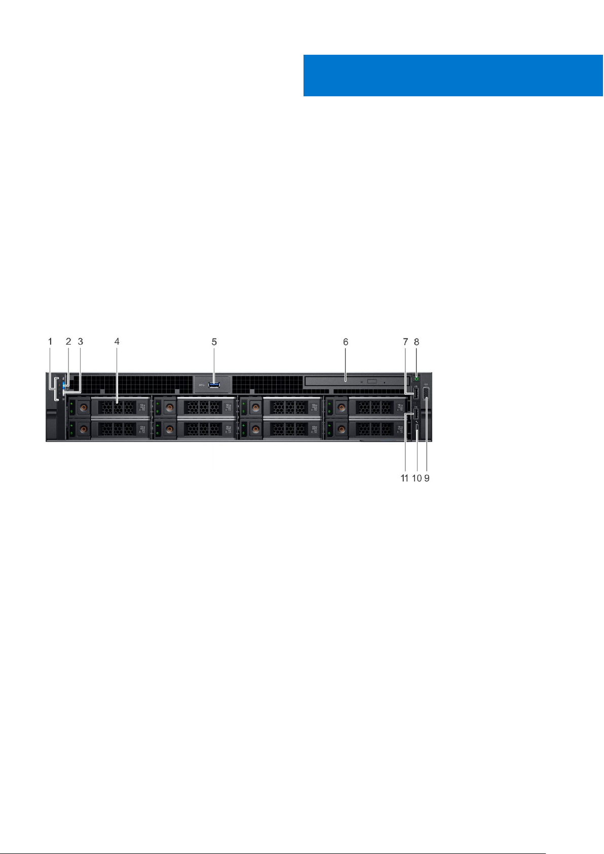
Front chassis view
2
Chassis View
1. System Status Indicator 2. System health and system ID
3. iDRAC Quick Sync 2 wireless indicator 4. Hard drive (x8)
5. USB 3.0 connector 6. Optical-drive (optional)
7. USB 2.0 connector 8. Power button/Power light
9. VGA connector 10. USB management port/iDRAC Direct
11. USB 2.0 connector
8 Chassis View
Page 9
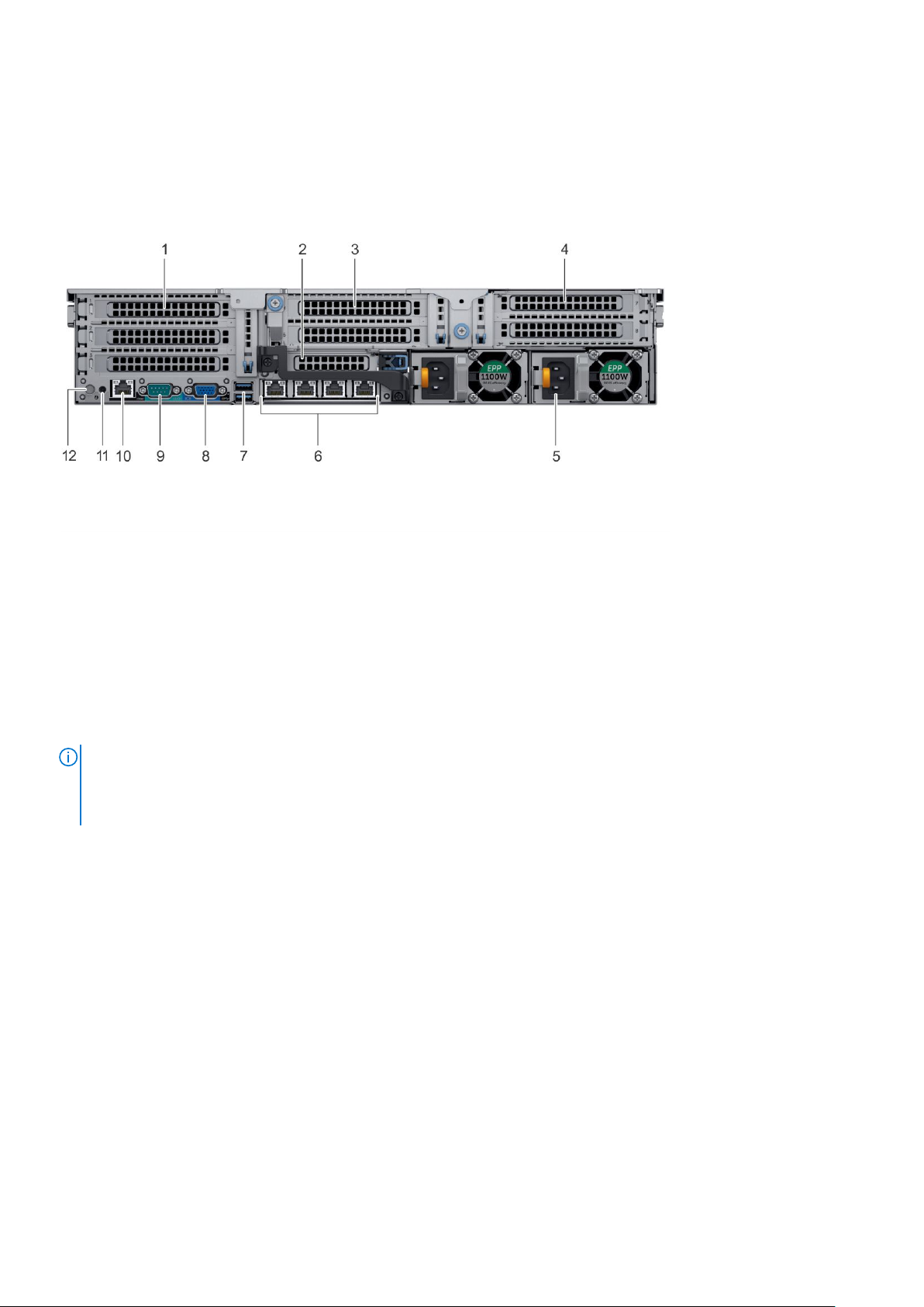
Back chassis view
1. PCIe expansion card slots 2. PCIe expansion card slots
3. PCIe expansion card slots 4. PCIe expansion card slots
5. Power supply (x2) 6. Network connectors (x4)
7. USB 3.0 connectors (x2) 8. VGA connector
9. Serial connector 10. iDRAC9 Enterprise Network connector
11. System identification connector 12. System identification button
Inside the system
NOTE:
Many repairs may only be done by a certified service technician. You should only perform troubleshooting and simple
repairs as authorized in your product documentation, or as directed by the online or telephone service and support team.
Damage due to servicing that is not authorized by Dell is not covered by your warranty. Read and follow the safety
instructions that are shipped with your product.
Chassis View 9
Page 10
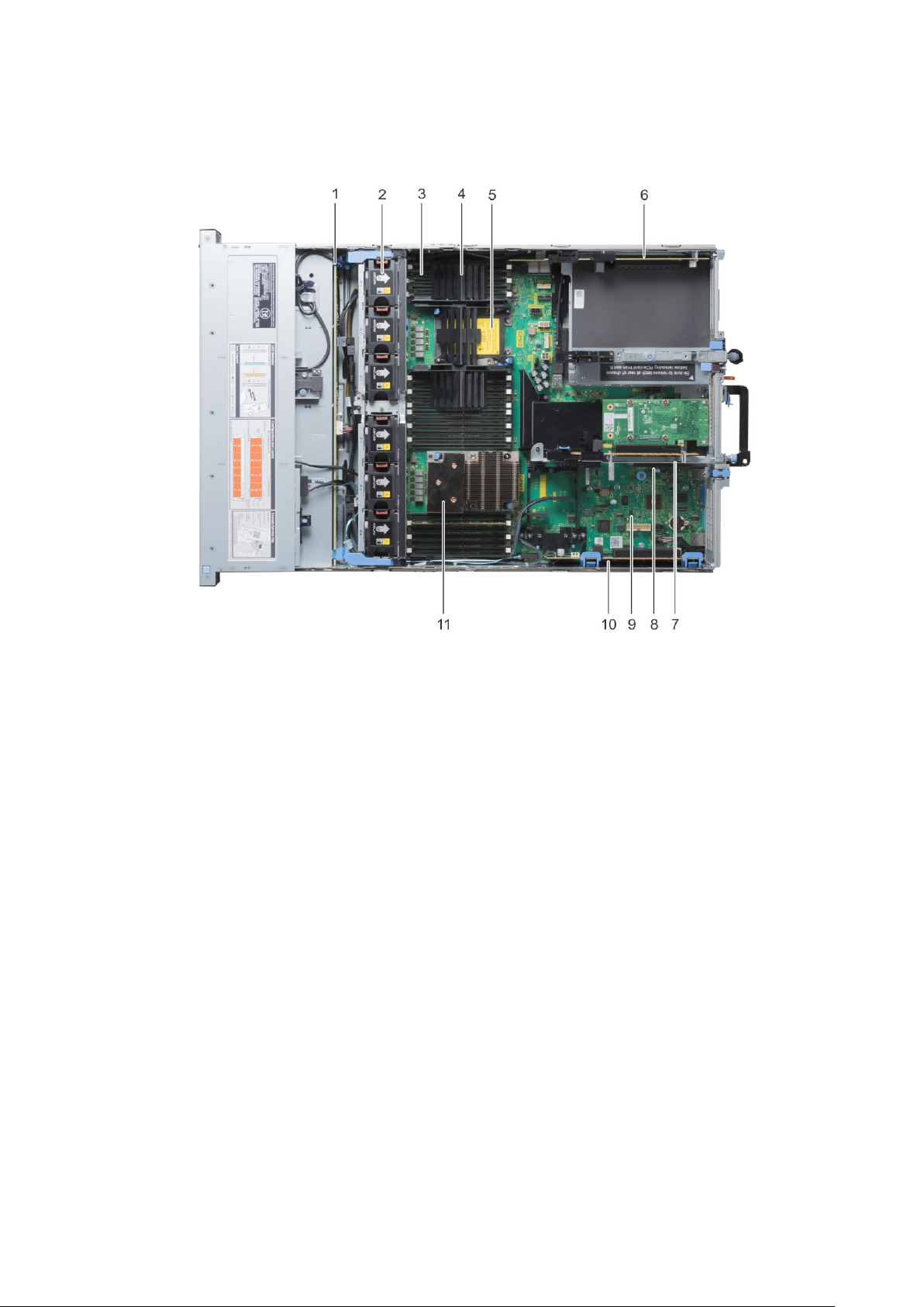
Figure 1. Inside chassis view
1. hard drive backplane
2. cooling fan (6) in the cooling fan assembly
3. DIMM sockets
4. CPU DIMM blank
5. CPU 2
6. expansion card riser 3A
7. expansion card riser 2A
8. VFlash connector
9. system board
10. expansion card riser 1C
11. CPU 1
LCD panel
The LCD panel provides system information, status, and error messages to indicate if the system is functioning correctly or
requires attention. The LCD panel can also be used to configure or view the system’s iDRAC IP address. For information about
the event and error messages generated by the system firmware and agents that monitor system components, see the Error
Code Lookup page at qrl.dell.com.
The LCD panel is available only on the optional front bezel. The optional front bezel is hot pluggable.
The statuses and conditions of the LCD panel are outlined here:
● The LCD backlight is white during normal operating conditions.
10
Chassis View
Page 11
● When the system needs attention, the LCD backlight turns amber, and displays an error code followed by descriptive text.
NOTE: If the system is connected to a power source and an error is detected, the LCD turns amber regardless of
whether the system is turned on or off.
● When the system turns off and there are no errors, LCD enters the standby mode after five minutes of inactivity. Press any
button on the LCD to turn it on.
● If the LCD panel stops responding, remove the bezel and reinstall it.
If the problem persists, see Getting help section.
● The LCD backlight remains off if LCD messaging is turned off using the iDRAC utility, the LCD panel, or other tools.
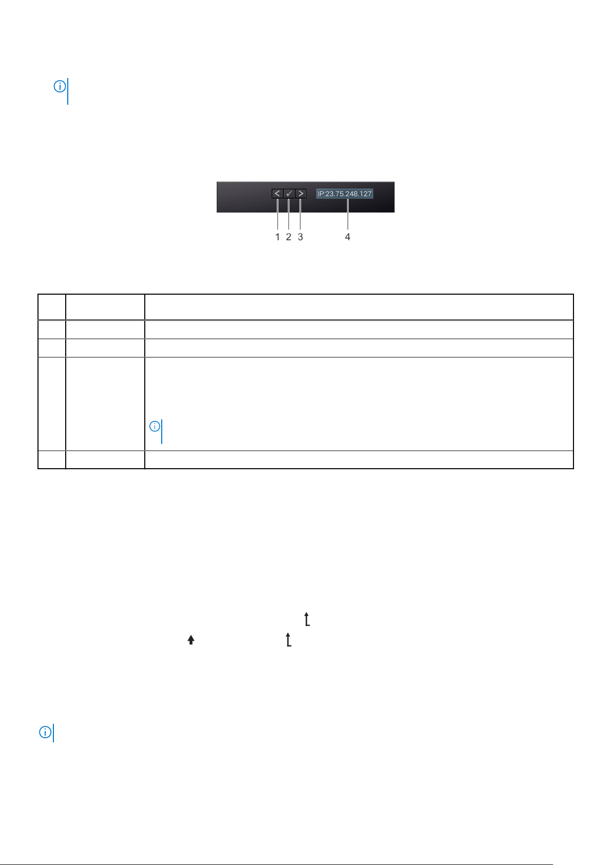
Figure 2. LCD panel features
Table 1. LCD panel features
Item Button or
display
1 Left Moves the cursor back in one-step increments.
2 Select Selects the menu item highlighted by the cursor.
3 Right Moves the cursor forward in one-step increments.
4 LCD display Displays system information, status, and error messages or iDRAC IP address.
Description
During message scrolling:
● Press and hold the right button to increase scrolling speed.
● Release the button to stop.
NOTE: The display stops scrolling when the button is released. After 45 seconds of inactivity,
the display starts scrolling.
Viewing Home screen
The Home screen displays user-configurable information about the system. This screen is displayed during normal system
operation when there are no status messages or errors. When the system turns off and there are no errors, LCD enters the
standby mode after five minutes of inactivity. Press any button on the LCD to turn it on.
Steps
1. To view the Home screen, press one of the three navigation buttons (Select, Left, or Right).
2. To navigate to the Home screen from another menu, complete the following steps:
a. Press and hold the navigation button until the up arrow is displayed.
b. Navigate to the Home icon using the up arrow .
c. Select the Home icon.
d. On the Home screen, press the Select button to enter the main menu.
Setup menu
NOTE: When you select an option in the Setup menu, you must confirm the option before proceeding to the next action.
Chassis View 11
Page 12

Option Description
iDRAC Select DHCP or Static IP to configure the network mode. If Static IP is selected, the available fields are
IP, Subnet (Sub), and Gateway (Gtw). Select Setup DNS to enable DNS and to view domain
addresses. Two separate DNS entries are available.
Set error Select SEL to view LCD error messages in a format that matches the IPMI description in the SEL. This
enables you to match an LCD message with an SEL entry.
Select Simple to view LCD error messages in a simplified user-friendly description.
Set home Select the default information to be displayed on the Home screen. See View menu section for the
options and option items that can be set as the default on the Home screen.
View menu
NOTE: When you select an option in the View menu, you must confirm the option before proceeding to the next action.
Option Description
iDRAC IP Displays the IPv4 or IPv6 addresses for iDRAC9. Addresses include DNS (Primary and Secondary),
Gateway, IP, and Subnet (IPv6 does not have Subnet).
MAC Displays the MAC addresses for iDRAC, iSCSI, or Network devices.
Name Displays the name of the Host, Model, or User String for the system.
Number Displays the Asset tag or the Service tag for the system.
Power Displays the power output of the system in BTU/hr or Watts. The display format can be configured in the
Set home submenu of the Setup menu.
Temperature Displays the temperature of the system in Celsius or Fahrenheit. The display format can be configured in
the Set home submenu of the Setup menu.
12 Chassis View
Page 13

Product Overview
The following pages contain information about Dell Precision 7920 Rack product overview.
Topics:
• System information label
System information label
Precision 7920 Rack – Front system information label
3
Figure 3. LED Behavior, Express Service Tag, Configuration and Layout
Precision 7920 Rack – Service information
Figure 4. System touchpoint, electrical overview, jumper settings and memory information
Product Overview 13
Page 14

Topics:
• Product Positioning
Recommended tools
•
• Need to know
• Diagnostics and indicators
• Chassis LEDs
• Jumpers and connectors
• Disassembly and reassembly
• GPU Host Card Installation
• Updating BIOS
• Restoring the Service Tag using Easy Restore
• Installation
• Accessing system information by using QRL
Product Positioning
4
Disassembly and reassembly
The Precision 7920 Rack is a general-purpose platform with highly expandable memory (up to 1536 GB), massive storage
capacity and impressive I/O capability to match. The Precision 7920 Rack adds extraordinary storage capacity options, making it
well-suited for data intensive applications that require greater storage, while not sacrificing I/O performance.
● Performance
○ Two Intel Xeon Skylake Processor Scalable Family processors
○ Twenty four DIMM Slot supporting up total up to 1.5TB of memory
○ Support total up to eight hard drives.
● Availability
○ Redundant power supply units (PSUs)
○ Hot-plug and hot-swappable PSUs, hard disk drives, and fans
○ PERC9/PERC10/Chipset SATA.
○ Internal vFLASH card
○ iDRAC9 Express or Enterprise with Dell Lifecycle Controller
○ Optional iDRAC Quick Sync II
● Expandability, I/O Storage
○
Only 8x 3.5" SAS,SATA(front) hard drives
○ Up to eight optional NVMe Express Flash PCIe SSDs with two PCIe Zoom4 cards.
○ System Network Architecture (SNA): 4x 1GbE or 2x 10GbE + 2x 1GbE
○ Choice of RAID options for even higher performance
14 Disassembly and reassembly
Page 15
Recommended tools
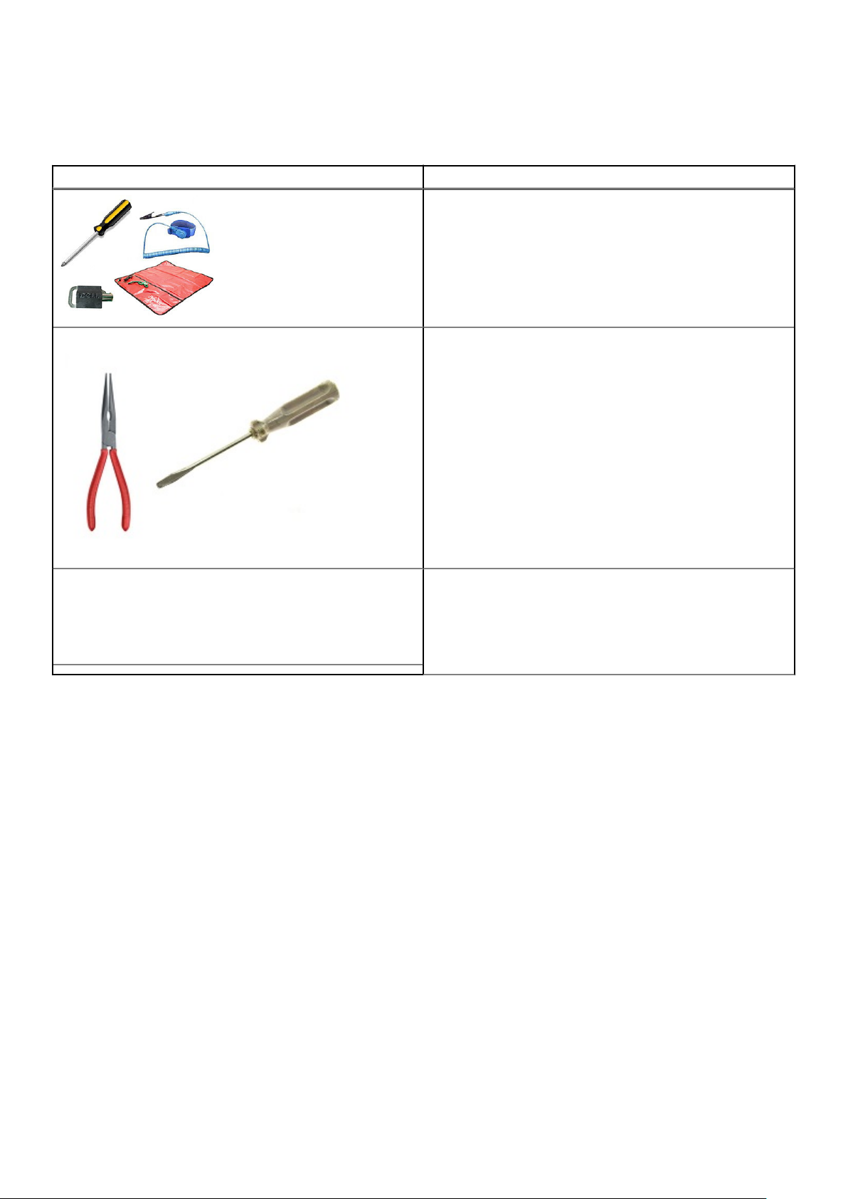
Table 2. Recommended tools and optional tools
Recommended tools Optional tools
● Key to the system keylock
● #1 and #2 Phillips screwdriver
● T30 and T8 Torx screwdrivers
● Wrist-grounding strap connected to the ground
● ESD Mat
● Needle-nose pliers to disconnect cables and connectors in
hard-to-reach locations
● Small flat-head screwdriver to disconnect small cables
from boards
Need to know
Before you begin servicing the system, you must read the following information:
● Critical callouts
● Common error codes
● Version control for BIOS/ Firmware/ Software
● Startup/Shutdown sequence
Common error messages
The Event Message Reference contains the error and event information generated by firmware and other agents that monitor
system components. These events might be logged, presented to the user on one of the system management consoles, or both
logged and displayed.
Each event consists of the following fields:
Disassembly and reassembly
15
Page 16

Table 3. Common error messages
Event Message Fields
Item Description
Message ID The unique alphanumeric identifier for the event. This identifier can be up
to eight characters long and consist of two parts:
● Message ID Prefix — Up to four alphabetic characters.
● Message ID Sequence — Up to four numeric digits.
Message The message text that is displayed to the user or logged as a result of
the event. If the message has variable content in it, the variable
substitution is reflected by text in italics. The substitution variables are
described in the Arguments field of the event.
Arguments Describes the values for any substitution variables appearing in the event
message text. If there is no variable content in the message, this field is
omitted from the event description.
Detailed Description Additional information describing the event.
Recommended Response Action The recommended action to remedy the event described. The response
action can vary based on the specific platform.
Category Dell Lifecycle Controller log filter used to select a subset of messages
from different domains or agents.
Subcategory Additional filter to further subset the event.
Trap/EventID The identification number used as the Trap ID for SNMP alert traps and
as the Event ID when the message is logged in operating system logs.
Severity The classification of the event based on its impact to the platform or
system. The severity can be:
● Severity 1 Critical — Indicates a catastrophic production problem that
might severely impact production systems or components, or systems
are down or not functioning.
● Severity 2 Warning — Indicates a high-impact problem where a
system or component is disrupted but can remain productive and
perform business-level operations.
● Severity 3 Information — Indicates a medium-to-low impact problem
that involves a partial or noncritical loss of functionality; operations
are impaired but can continue to function.
LCD Message The event message text that is displayed on the system's LCD.
Initial Default Event messages result in event actions such as logging, SNMP or email
alerts. Generally, the event actions are configurable using the Dell iDRAC
event action filtering feature. This item describes the initial default and
possible event actions for the message.
Event Action Filter Describes additional configurable actions that are available for the event
action for this message. This information is presented in a table, and each
entry has a value of TRUE or FALSE to indicate its applicability.
● Filter Visibility — Event visible to iDRAC event filtering.
● IPMI Alert — Event can generate an IMPI alert.
● SNMP Alert — Event can generate an SNMP trap.
● Email Alert — Event can generate an email alert.
● LC Log — Event can generate a Dell Lifecycle Controller log entry.
● LCD — Event is displayed on the system's LCD.
● Power Off — Event can cause the system to power off.
Power Cycle — Event can cause the system to perform a power
●
cycle.
● Reset — Event can cause the system to perform a reset.
For more information on the list of error and event messages, see the Dell Event Messages Reference Guide
16
Disassembly and reassembly
Page 17

Startup-Shutdown sequence
NOTE: Precision 7920 Rack BIOS is pure UEFI with a legacy compatibility layer. This layer is called the Compatibility
Support Module.
New POST display
The following are the POST display enhancements:
● The look of the boot process has been revamped for Precision 7920 Rack.
● The Dell high-resolution splash screen displays instantly after power-on.
● Both a progress bar and descriptive text appear on-screen.
● Hotkey behavior remains unchanged (<F2> still takes you to System Setup).
● There is a uniform look and feel through the boot process (one exception — the system will drop to text mode briefly to run
legacy option ROMs when booting in legacy mode).
● POST error messages are now compliant with Error Exception Message Initiative (EEMI).
NOTE: All POST error and warning messages will be logged in the LC log.
● UEFI option ROMs display error/warning messages on the screen via the Driver Health Protocol (DHP). The auto-repair logic
is also included in Boot Device Selection (BDS) just before booting. Show the repair GUI and load the controller formset if
EfiDriverHealthStatsuConfigurationRequired status is returned.
Enhanced boot support
The following lists the boot support enhancements:
● Enhanced method to change the boot list based on Fully Qualified Descriptors (FQDDs). This allows for systems
management consoles and the factory to specify a boot list for devices that are not currently present, for example, disabled
NDC or other boot mode.
● New ability to toggle between LC and BIOS.
● The Boot Manager (<F11>) and BIOS Setup (<F2>) will only contain the boot option enumeration of the current Boot mode.
● Completely revised boot flow.
Diagnostics and indicators
The following pages contain the information about diagnostics and indicators for Precision 7920 Rack.
Chassis LEDs
The following pages contain the information about the chassis LEDs.
Status LED indicators
NOTE: The diagnostic indicators are not present if the system is equipped with an LCD display.
NOTE: The status LED indicators are always off and only turns on to a solid amber if any error occurs.
Table 4. Status LED indicators and descriptions
Icon Description Condition Corrective action
Health indicator The indicator turns solid blue if the
is in good health.
The indicator blinks amber:
● When the is turned on.
None required.
Check the System Event Log or system messages
for the specific issue. For more information about
Disassembly and reassembly 17
Page 18
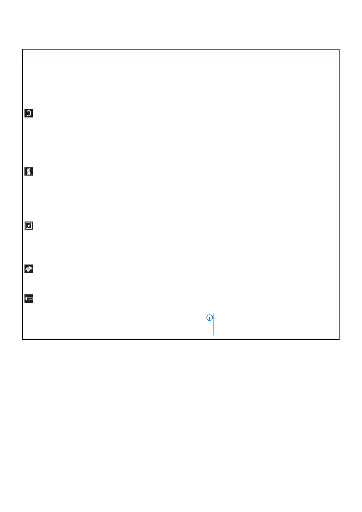
Table 4. Status LED indicators and descriptions (continued)
Icon Description Condition Corrective action
● When the is in standby.
● If any error condition exists. For
example, a failed fan, PSU, or a
hard drive.
error messages, see the Dell Event and Error
Messages Reference Guide at Dell.com/
openmanagemanuals > OpenManage software.
The POST process is interrupted without any video
output due to invalid memory configurations. See the
Getting help section.
Drive indicator The indicator turns solid amber if
there is a drive error.
Temperature
indicator
Electrical
indicator
Memory indicator The indicator turns solid amber if a
PCIe indicator The indicator turns solid amber if a
The indicator turns solid amber if
the system experiences a thermal
error (for example, the ambient
temperature is out of range or
there is a fan failure).
The indicator turns solid amber if
the system experiences an
electrical error (for example,
voltage out of range, or a failed
power supply unit (PSU) or voltage
regulator).
memory error occurs.
PCIe card experiences an error.
● Check the System Event Log to determine if the
drive has an error.
● Run the appropriate Online Diagnostics test.
Restart the system and run embedded
diagnostics (ePSA).
● If the drives are configured in a RAID array,
restart the system, and enter the host adapter
configuration utility program.
Ensure that none of the following conditions exist:
● A cooling fan has been removed or has failed.
● System cover, air shroud, memory module blank,
or back filler bracket is removed.
● Ambient temperature is too high.
● External airflow is obstructed.
If the problem persists, see the Getting help section.
Check the System Event Log or system messages
for the specific issue. If it is due to a problem with
the PSU, check the LED on the PSU. Reseat the
PSU. If the problem persists, see the Getting help
section.
Check the System Event Log or system messages
for the location of the failed memory. Reseat the
memory module. If the problem persists, see the
Getting help section.
Restart the system. Update any required drivers for
the PCIe card. Reinstall the card. If the problem
persists, see the Getting help section.
NOTE: For more information about the
supported PCIe cards, see the Expansion card
installation guidelines section.
18 Disassembly and reassembly
Page 19
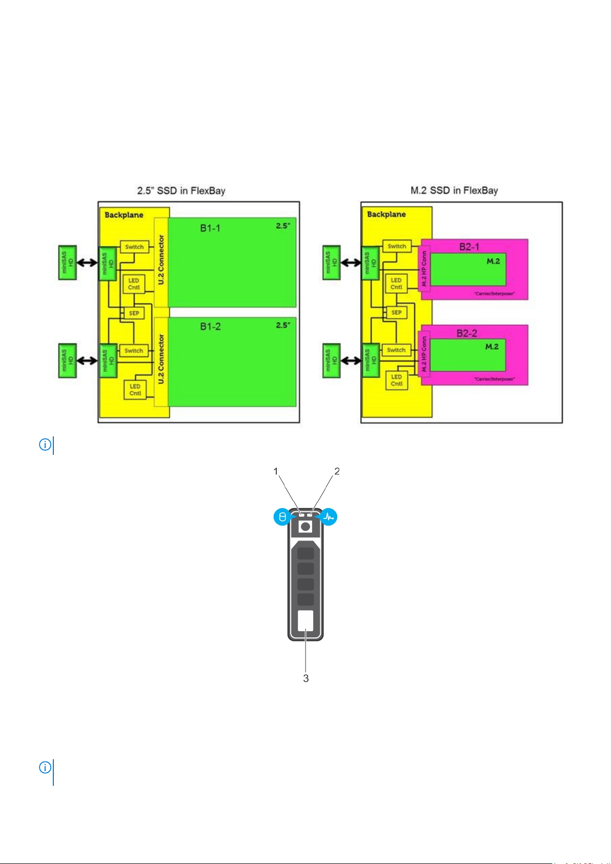
Hard drive indicator codes
Each hard drive carrier has an activity LED indicator and a status LED indicator. The indicators provide information about the
current status of the hard drive. The activity LED indicator indicates whether the hard drive is currently in use or not. The status
LED indicator indicates the power condition of the drive.
Hard drive indicators
NOTE: LED status or activity indicators will only work with a backplane with each carriers shown below.
Figure 5. Hard drive indicators
1. hard drive activity LED indicator
2. hard drive status LED indicator
3. hard drive
If the hard drive is in the Advanced Host Controller Interface (AHCI) mode, the status LED indicator does not turn
NOTE:
on.
Disassembly and reassembly 19
Page 20
NOTE: Drive status indicator behavior is managed by Storage Spaces Direct. Not all drive status indicators may be used.
Table 5. Hard drive indicator codes
Hard drive status indicator code Condition
Flashes green twice per second Identifying drive or preparing for removal.
Off Drive ready for removal.
NOTE: The drive status indicator remains off until all drives
are initialized after the system is turned on. Drives are not
ready for removal during this time.
Flashes green, amber, and then turns off Predicted drive failure.
Flashes amber four times per second Drive failed.
Flashes green slowly Drive rebuilding.
Solid green Drive online.
Flashes green for three seconds, amber for three
seconds, and then turns off after six seconds
Rebuild stopped.
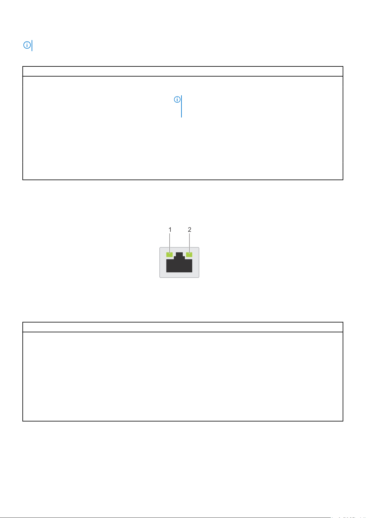
NIC indicator codes
Each NIC on the back of the system has indicators that provide information about the activity and link status. The activity LED
indicator indicates if data is flowing through the NIC, and the link LED indicator indicates the speed of the connected network.
Figure 6. NIC indicator codes
1. Link LED indicator
2. Activity LED indicator
Table 6. NIC indicator codes
Status Condition
Link and activity indicators are off. The NIC is not connected to the network.
Link indicator is green, and activity indicator is blinking
green.
Link indicator is amber, and activity indicator is blinking
green.
Link indicator is green, and activity indicator is off. The NIC is connected to a valid network at its maximum port speed,
Link indicator is amber, and activity indicator is off. The NIC is connected to a valid network at less than its maximum
Link indicator is blinking green, and activity is off. NIC identify is enabled through the NIC configuration utility.
The NIC is connected to a valid network at its maximum port speed,
and data is being sent or received.
The NIC is connected to a valid network at less than its maximum
port speed, and data is being sent or received.
and data is not being sent or received.
port speed, and data is not being sent or received.
Power supply unit indicator codes
AC power supply units (PSUs) have an illuminated translucent handle that serves as an indicator. The indicator shows whether
power is present or a power fault has occurred.
20
Disassembly and reassembly
Page 21
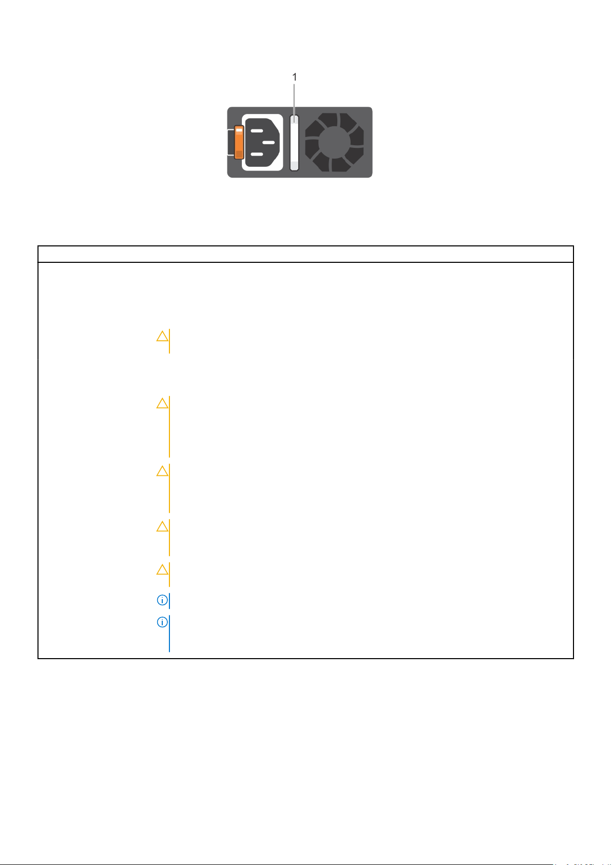
Figure 7. AC PSU status indicator
1. AC PSU status indicator/handle
Table 7. AC PSU status indicator codes
Power indicator codes Condition
Green A valid power source is connected to the PSU and the PSU is operational.
Blinking amber Indicates a problem with the PSU.
Not illuminated Power is not connected to the PSU.
Blinking green When the firmware of the PSU is being updated, the PSU handle blinks green.
CAUTION: Do not disconnect the power cord or unplug the PSU when updating
firmware. If firmware update is interrupted, the PSUs do not function.
Blinking green and turns
off
When hot-plugging a PSU, the PSU handle blinks green five times at a rate of 4 Hz and turns off.
This indicates a PSU mismatch with respect to efficiency, feature set, health status, or supported
voltage.
CAUTION: If two PSUs are installed, both the PSUs must have the same type of label.
For example, Extended Power Performance (EPP) label. Mixing PSUs from previous
generations of Precision Workstation is not supported, even if the PSUs have the
same power rating. This results in a PSU mismatch condition or failure to turn the
system on.
CAUTION: When correcting a PSU mismatch, replace only the PSU with the blinking
indicator. Swapping the PSU to make a matched pair can result in an error condition
and unexpected system shutdown. To change from a high output configuration to a
low output configuration or vice versa, you must turn off the system.
CAUTION: AC PSUs support both 240 V and 120 V input voltages with the exception of
Titanium PSUs, which support only 240 V. When two identical PSUs receive different
input voltages, they can output different wattages, and trigger a mismatch.
CAUTION: If two PSUs are used, they must be of the same type and have the same
maximum output power.
NOTE: Ensure that both the PSUs are of the same capacity.
NOTE: Mixing PSUs (even the PSUs that have the same power rating) from previous
generations of Precision Workstation is not supported. This results in a PSU mismatch
condition or failure to turn the system on.
iDRAC Direct LED indicator codes
The iDRAC Direct LED indicator lights up to indicate that the port is connected and is being used as a part of the iDRAC
subsystem.
iDRAC Direct LED indicator is located below the iDRAC Direct port on the right control panel.
You can configure iDRAC Direct by using a USB to micro USB (type AB) cable, which you can connect to your laptop or tablet.
The following table describes iDRAC Direct activity when the iDRAC Direct port is active:
Disassembly and reassembly
21
Page 22

Table 8. iDRAC Direct LED indicator codes
iDRAC Direct LED
indicator code
Solid green for two
seconds
Flashing green (on for
two seconds and off for
two seconds)
Turns off Indicates that the laptop or tablet is unplugged.
Condition
Indicates that the laptop or tablet is connected.
Indicates that the laptop or tablet connected is recognized.
iDRAC Quick Sync 2 indicator codes
iDRAC Quick Sync 2 module (optional) is on the front panel of your system.
Figure 8. iDRAC Quick Sync 2 indicator
Table 9. iDRAC Quick Sync 2 indicators and descriptions
iDRAC Quick Sync 2 indicator
code
Off (default state) Indicates that the iDRAC Quick Sync 2
Solid white Indicates that iDRAC Quick Sync 2 is
Blinks white rapidly Indicates data transfer activity. NA
Condition Corrective action
feature is turned off. Press the iDRAC
Quick Sync 2 button to turn on the
iDRAC Quick Sync 2 feature.
ready to communicate. Press the iDRAC
Quick Sync 2 button to turn off.
If the LED fails to turn on, reset the left control
panel flex cable and check. If the problem
persists, see the Getting help section.
If the LED fails to turn off, restart the system. If
the problem persists, see the Getting help
section.
If the problem persists, see the Getting help
section.
Blinks white slowly Indicates that firmware update is in
progress.
Blinks white five times rapidly
and then turns off
Solid amber Indicates that the system is in fail-safe
Blinking amber Indicates that the iDRAC Quick Sync 2
22 Disassembly and reassembly
Indicates that the iDRAC Quick Sync 2
feature is disabled.
mode.
hardware is not responding properly.
NA
If the indicator continues to blink indefinitely, see
the Getting help section.
Check if iDRAC Quick Sync 2 feature is
configured to be disabled by iDRAC.
If the problem persists, see the Getting help
section.
For more information, see Integrated Dell Remote
Access Controller User's Guide at dell.com/
idracmanuals or Dell OpenManage Server
Administrator User’s Guide at dell.com/
openmanagemanuals .
Restart the system.
If the problem persists, see the Getting help
section.
Restart the system.
Page 23
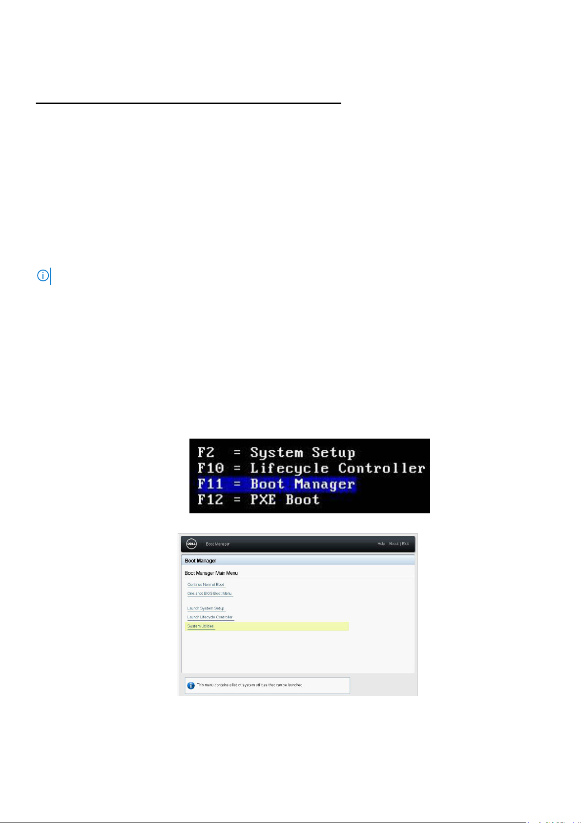
Table 9. iDRAC Quick Sync 2 indicators and descriptions (continued)
iDRAC Quick Sync 2 indicator
code
Condition Corrective action
If the problem persists, see the Getting help
section.
Enhanced Preboot System Assessment
If you experience a problem with your system, run the system diagnostics before contacting Dell for technical assistance. The
purpose of running system diagnostics is to test your system hardware without requiring more equipment or risking data loss. If
you are unable to fix the problem yourself, service and support personnel can use the diagnostics results to help you solve the
problem.
Dell Embedded system diagnostics
NOTE: The Dell Embedded System Diagnostics is also known as Enhanced Preboot System Assessment (ePSA) diagnostics.
The embedded system diagnostics provides a set of options for particular device groups or devices allowing you to:
● Run tests automatically or in an interactive mode.
● Repeat tests
● Display or save test results.
● Introduce more test options for extra information about the failed devices, run a thorough test.
● View status messages that inform you if tests are completed successfully.
● View error messages that inform you of problems encountered during testing.
Running the Embedded system diagnostics from Boot Manager
To run the embedded system diagnostics from Boot Manager:
1. As the system boots, press <F11>.
2. Using the arrow keys select System Utilities → Launch Diagnostics.
Figure 9. Boot Manager Main Menu
Disassembly and reassembly
23
Page 24
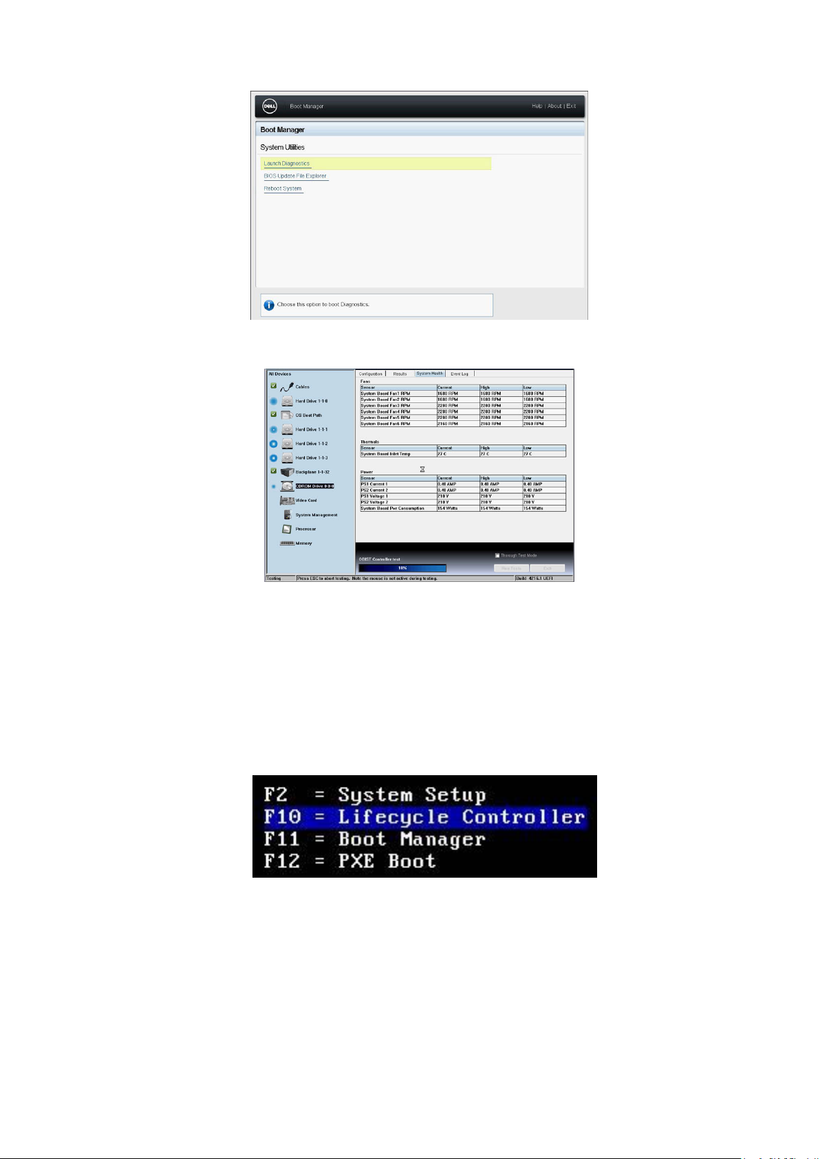
Figure 10. System Utilities
3. Wait while the Quick Tests automatically run.
Figure 11. Quick Test
4. Once the tests have been completed, you can view the results and additional information on the Results tab, the System
Health tab, the Configuration tab, and the Event Log tab.
5. Close the Embedded System Diagnostics utility.
6. To leave the diagnostics, click Exit.
7. Click OK when prompted, and the system reboots.
Running the Embedded System Diagnostics from the Dell Lifecycle Controller
To run the embedded system diagnostics from the Dell Lifecycle Controller:
As the system boots, press F10.
1.
24
Disassembly and reassembly
Page 25

2. Select Hardware Diagnostics → Run Hardware Diagnostics.
Jumpers and connectors
This topic provides specific information about the jumpers. It also provides some basic information about jumpers and switches
and describes the connectors on the various boards in the system. Jumpers on the system board help to disable the system and
setup passwords. You must know the connectors on the system board to install components and cables correctly.
Disassembly and reassembly 25
Page 26
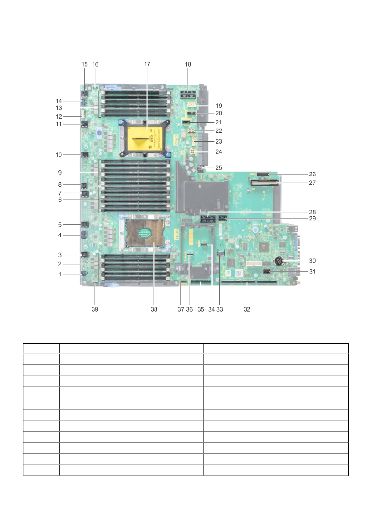
System board jumpers and connectors
Figure 12. System board jumpers and connectors
Table 10. System board jumpers and connectors
Item Connector Description
1 J_ODD Optical drive power connector
2 A7, A1, A8, A2, A9, A3 Memory module sockets
3 J_FAN2U_6 Cooling fan 6 connector
4 J_BP3 Backplane 3 power connector
5 J_FAN2U_5 Cooling fan 5 connector
6 A6, A12, A5, A11, A4, A10 Memory module sockets
7 J_FAN2U_4 Cooling fan 4 connector
8 INTRUSION_DET Intrusion switch connector
9 B7, B1, B8, B2, B9, B3 Memory module sockets
10 J_FAN2U_3 Cooling fan 3 connector
11 J_FAN2U_2 Cooling fan 2 connector
26 Disassembly and reassembly
Page 27

Table 10. System board jumpers and connectors (continued)
Item Connector Description
12 J_BP_SIG1 Backplane 1 signal connector
13 B6, B12, B5, B11, B4, B10 Memory module sockets
14 J_BP1 Backplane 1 power connector
15 J_FAN2U_1 Cooling fan 1 connector
16 P_LFT_CP Left control panel connector
17 CPU2 CPU2 processor and heat sink module socket (with
dust cover)
18 J_R3_X24 Riser 3 connector
19 J_BP_SIG2 Backplane 2 signal connector
20 J_BP_SIG0 Backplane 0 signal connector
21 J_BP0 (RSR3_225W) Backplane 0 power connector (Riser 3 PCIe 225 W
power)
22 J_BP2 (RSR2_225W) Backplane 2 power connector (Riser 2 PCIe 225 W
power)
23 J_BATT_SIG NVDIMM-N battery signal connector
24 J_BATT_PWR NVDIMM-N battery power connector
25 J_USB_INT Internal USB connector
26 J_IDSDM IDSDM/vFlash connector
27 J_NDC NDC connector
28 J_R2_X24_IT9 Riser 2 connector
29 J_R2_3R_X8_IT9 Riser 2 connector
30 BATTERY Battery connector
31 J_FRONT_VIDEO Video connector
32 J_R1_SS82_3 and J_R1_SS60_1 Riser 1 connector
33 J_TPM_MODULE TPM connector
34 J_SATA_B SATA B connector
35 J_R1_SS82_1 Riser 1 connector (Mini PERC option)
36 J_SATA_A SATA A connector
37 J_SATA_C SATA C connector (Optical drive SATA connector)
38 CPU1 CPU1 processor and heat sink module
39 P_RGT_CP Right control panel connector
System board jumper settings
For information on resetting the password jumper to disable a password, see the Disabling a forgotten password section.
Table 11. System board jumper settings
Jumper Setting Description
PWRD_EN The BIOS local access is protected with the software security
features.
Disassembly and reassembly 27
Page 28

Table 11. System board jumper settings (continued)
Jumper Setting Description
The BIOS local access security features are unlocked on the
next AC power cycle.
NVRAM_CLR The BIOS configuration settings are retained at system boot.
The BIOS configuration settings are cleared at system boot.
Disabling forgotten password
The software security features of the system include a system password and a setup password. The password jumper enables or
disables password features and clears any password(s) currently in use.
Prerequisites
CAUTION: Many repairs may only be done by a certified service technician. You should only perform
troubleshooting and simple repairs as authorized in your product documentation, or as directed by the online or
telephone service and support team. Damage due to servicing that is not authorized by Dell is not covered by
your warranty. Read and follow the safety instructions that are shipped with your product.
Steps
1. Turn off the system, including any attached peripherals, and disconnect the system from the electrical outlet.
2. Remove the system cover.
3. Move the jumper on the system board jumper from pins 2 and 4 (default) to pins 4 and 6.
4. Install the system cover.
The existing passwords are not disabled (erased) until the system boots with the jumper on pins 4 and 6. However, before
you assign a new system and/or setup password, you must move the jumper back to pins 2 and 4.
NOTE:
If you assign a new system and/or setup password with the jumper on pins 4 and 6, the system disables the new
password(s) the next time it boots.
5. Reconnect the system to its electrical outlet and turn on the system, including any attached peripherals.
6. Turn off the system, including any attached peripherals, and disconnect the system from the electrical outlet.
7. Remove the system cover.
8. Move the jumper on the system board jumper from pins 4 and 6 to pins 2 and 4 (default).
9. Install the system cover.
10. Reconnect the system to its electrical outlet and turn on the system, including any attached peripherals.
11. Assign a new system and/or setup password.
Disassembly and reassembly
The following sections contain the procedures for removing and replacing system components.
Front Bezel
Removing the optional front bezel
Steps
1. Locate and remove the bezel key.
28
Disassembly and reassembly
Page 29
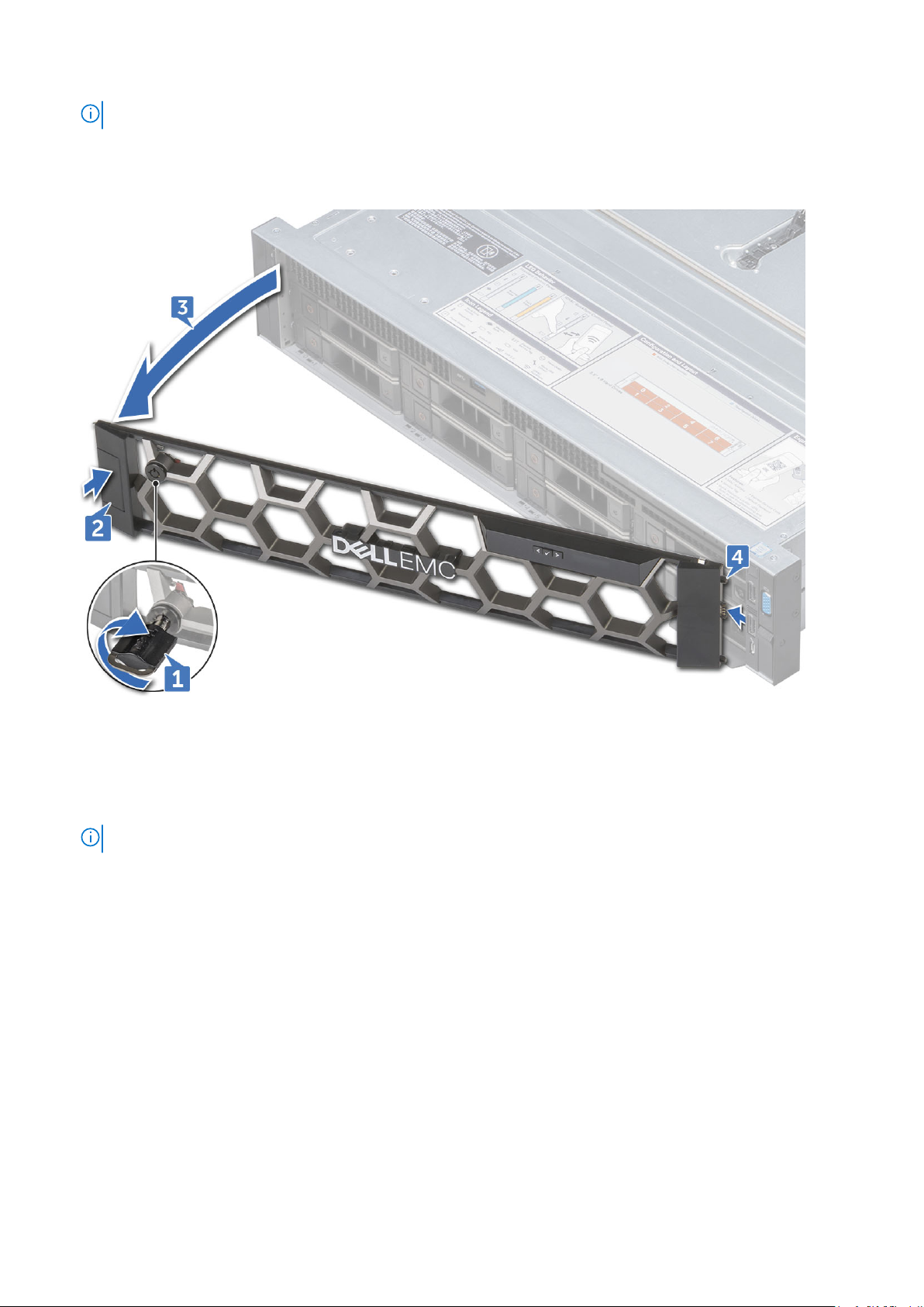
NOTE: The bezel key is attached to the LCD bezel package.
2. Unlock the bezel by using the key.
3. Press the release button to release the bezel, and pull the left end of the bezel.
4. Unhook the right end, and remove the bezel.
Installing the optional front bezel
Steps
1. Locate and remove the bezel key.
NOTE: The bezel key is attached to the LCD bezel package.
2. Align and insert the right end of the bezel onto the system .
3. Press the release button and fit the left end of the bezel onto the system.
4. Lock the bezel by using the key.
System cover
Removing system cover
Prerequisites
1. Turn off the system, including any attached peripherals.
2. Disconnect the system from the electrical outlet and disconnect the peripherals.
Steps
1. Using a flat head screwdriver, rotate the latch release lock counter clockwise to the unlocked position.
Disassembly and reassembly
29
Page 30
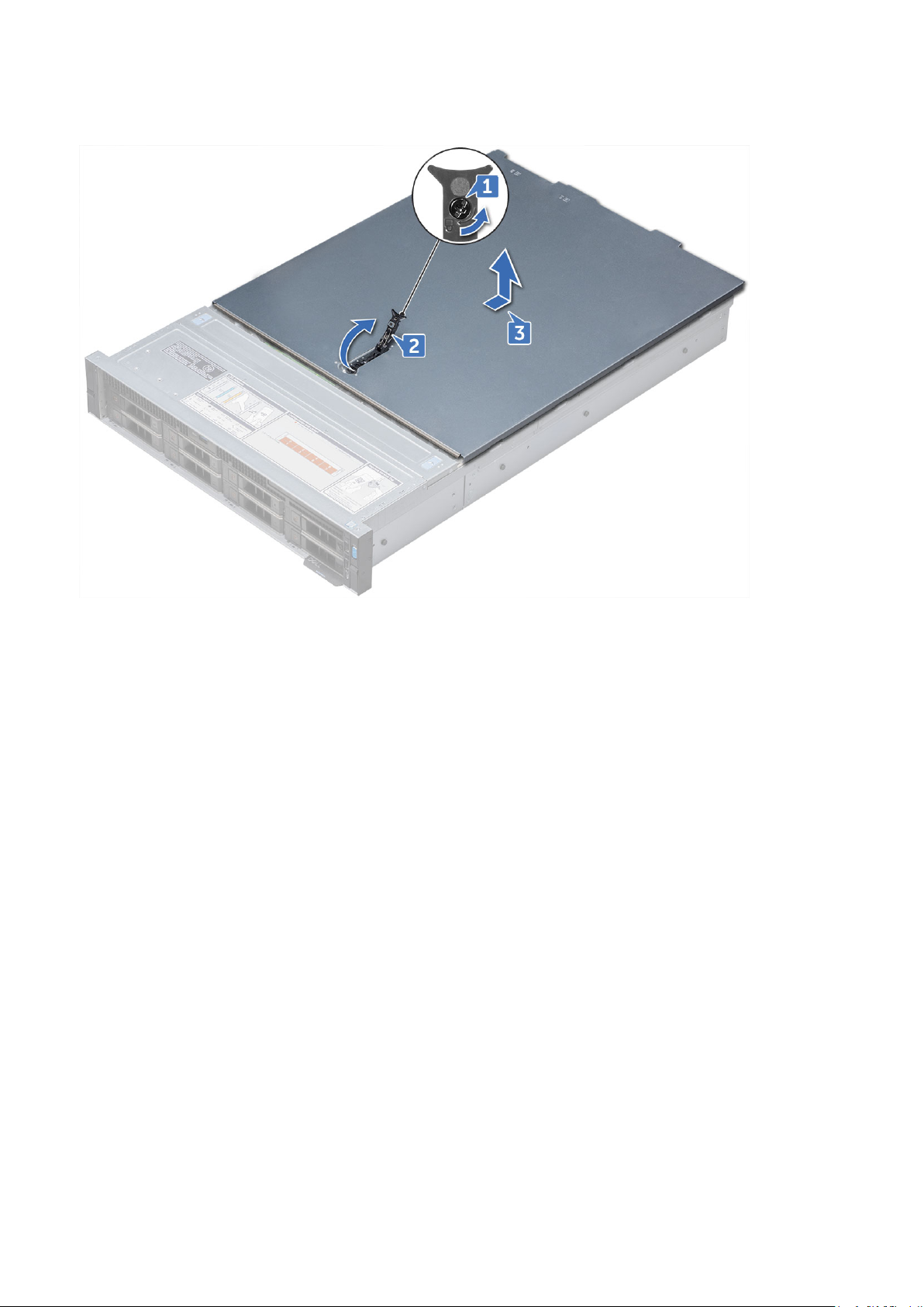
2. Lift the latch till the system cover slides back and the tabs on the system cover disengage from the slots on the system.
3. Hold the cover on both sides, and lift the cover away from the system.
Installing system cover
Prerequisites
1. Ensure that all internal cables are routed correctly and connected, and no tools or extra parts are left inside the system.
Steps
1. Align the tabs on the system cover with the slots on the system.
2. Push the system cover latch down.
3. Using a flat head screwdriver, rotate the latch release lock clockwise to the locked position.
Next steps
1. Reconnect the peripherals and connect the system to the electrical outlet.
2. Turn on the system, including any attached peripherals.
Optical drive
Removing optical drive
Prerequisites
1. If installed, remove the front bezel.
2. Remove the system cover.
Steps
1. Disconnect the optical drive cable from the optical drive.
2. Press the blue latch and slide the optical drive from the system.
30
Disassembly and reassembly
Page 31

Next steps
Install the optical drive.
Installing optical drive
Steps
1. Slide the optical drive to the system, until the locks into place.
2. Connect the optical drive cable on the optical drive.
3. Install system cover and front bezel if applicable.
Air shroud
Removing air shroud
Prerequisites
CAUTION:
Never operate your system with the air shroud removed. The system may get overheated quickly, resulting in
shutdown of the system and loss of data.
1. If installed, remove the full length PCIe cards.
2. If applicable, remove the GPU cards.
Steps
Hold the shroud at both ends and lift it away from the system.
Disassembly and reassembly
31
Page 32

Next steps
Install the shroud.
Installing air shroud
Prerequisites
1. If applicable, route the cables inside the system along the system wall and secure the cables by using the cable securing
bracket.
Steps
1. Align the tabs on the air shroud with the slots on the system.
2. Lower the air shroud into the system until it is firmly seated.
When firmly seated, the memory socket numbers marked on the air shroud align with the respective memory sockets.
Next steps
1. If removed, install the full length PCIe cards.
2. If applicable, install the GPU cards.
Cooling fan assembly
Removing cooling fan assembly
Steps
1. Lift the release levers to unlock the cooling fan assembly from the system.
2. Hold the release levers and lift the cooling fan assembly away of the system.
32
Disassembly and reassembly
Page 33

Installing cooling fan assembly
Steps
1. Align the guide rails on the cooling fan assembly with the standoffs on the system.
2. Lower the cooling fan assembly into the system until the cooling fan connectors engage with the connectors on the system
board.
3. Press the release levers to lock the cooling fan assembly into the system.
Cooling fans
Removing cooling fan
Prerequisites
NOTE:
Opening or removing the system cover when the system is ON may expose you to a risk of electric shock. Exercise
utmost care while removing or installing cooling fans.
NOTE: The system will shutdown if the system cover is removed before shutting down the system
CAUTION: The cooling fans are hot swappable. To maintain proper cooling while the system is on, replace only
one fan at a time.
Steps
Press the release tab and lift the cooling fan out of the cooling fan assembly.
Disassembly and reassembly
33
Page 34

Installing cooling fan
Steps
1. Holding the release tab, align the connector at the base of the cooling fan with the connector on the system board.
2. Slide the cooling fan into the cooling fan assembly until the release tab locks into place.
Intrusion switch
Removing intrusion switch
Prerequisites
1. Remove the cooling fan assembly.
Steps
Press the intrusion switch and slide it out of the from the intrusion switch slot.
34
Disassembly and reassembly
Page 35

Installing intrusion switch
Steps
1. Align the tabs on the intrusion switch with the slots on the cooling fan assembly.
2. Pull the intrusion switch up and push it until the switch locks in place.
Next steps
1. Install the cooling fan assembly.
Hard drive
Removing hard drive blank
Prerequisites
1. If installed, remove the front bezel.
CAUTION:
installed.
Steps
Press the release button and slide the hard drive blank out of the hard drive slot.
To maintain proper system cooling, all empty hard drive slots must have hard drive blanks
Disassembly and reassembly
35
Page 36

Installing hard drive blank
Steps
Insert the hard drive blank into the hard drive slot and push until the release button clicks into place.
Next steps
1. If removed, install the front bezel.
Removing hard drive
Prerequisites
1. If applicable, remove the front bezel.
2. Using the management software, prepare the hard drive for removal. If the hard drive is online, the green activity or fault
indicator flashes while the drive is turning off. When the hard drive indicators are off, the hard drive is ready for removal. For
more information, see the documentation for the storage controller.
CAUTION:
See the documentation supplied with your operating system.
CAUTION: Before attempting to remove or install a hard drive while the system is running, see the
documentation for the storage controller card to ensure that the host adapter is configured correctly to support
hard drive removal and insertion.
CAUTION: Mixing hard drives from previous generations of Precision Workstations is not supported.
To prevent data loss, ensure that your operating system supports hot swappable drive installation.
Steps
1. Press the release button to open the hard drive release handle.
2. Holding the handle, slide the hard drive out of the hard drive slot.
36
Disassembly and reassembly
Page 37

Next steps
Install the hard drive.
NOTE: If you are not replacing the hard drive immediately, insert a hard drive blank in the empty hard drive slot.
Installing hard drive
Prerequisites
CAUTION:
carrier and attempting to lock its handle next to a partially installed carrier can damage the partially installed
carrier's shield spring and make it unusable.
NOTE: To prevent data loss, ensure that your operating system supports hot-swap drive installation. See the
documentation supplied with your operating system.
NOTE: When a replacement hot swappable hard drive is installed and the system is powered on, the hard drive
automatically begins to rebuild. Make absolutely sure that the replacement hard drive is blank or contains data that you wish
to have over-written. Any data on the replacement hard drive is immediately lost after the hard drive is installed.
Steps
1. Press the release button on the front of the hard drive to open the release handle.
2. Insert the hard drive into the hard drive slot until the hard drive connects with the backplane.
3. Close the hard drive handle to lock the hard drive in place.
When installing a hard drive, ensure that the adjacent drives are fully installed. Inserting a hard drive
Disassembly and reassembly
37
Page 38

Figure 13. Installing hard drive
Next steps
If applicable, install the front bezel.
Removing 3.5 inch hard drive from hard drive carrier
Steps
1. Using Phillips #1 screwdriver, remove the screws from the slide rails on the hard drive carrier.
2. Lift the hard drive out of the hard drive carrier.
Next steps
Install hard drive into the hard drive carrier.
38
Disassembly and reassembly
Page 39

Installing 3.5 inch hard drive into hard drive carrier
Steps
1. Insert the hard drive into the hard drive carrier with the connector end of the hard drive toward the back of the carrier.
2. Align the screw holes on the hard drive with the screws holes on the hard drive carrier.
When aligned correctly, the back of the hard drive is flush with the back of the hard drive carrier.
3. Using the Phillips #1 screwdriver, tighten the screws to secure the hard drive to the hard drive carrier.
Removing hard drive
Prerequisites
1. If applicable, remove the front bezel.
2. Using the management software, prepare the hard drive for removal. If the hard drive is online, the green activity or fault
indicator flashes while the drive is turning off. When the hard drive indicators are off, the hard drive is ready for removal. For
more information, see the documentation for the storage controller.
CAUTION:
See the documentation supplied with your operating system.
CAUTION: Before attempting to remove or install a hard drive while the system is running, see the
documentation for the storage controller card to ensure that the host adapter is configured correctly to support
hard drive removal and insertion.
CAUTION: Mixing hard drives from previous generations of Precision Workstations is not supported.
Steps
1. Press the release button to open the hard drive release handle.
2. Holding the handle, slide the hard drive out of the hard drive slot.
To prevent data loss, ensure that your operating system supports hot swappable drive installation.
Disassembly and reassembly
39
Page 40

Next steps
Install the hard drive.
NOTE: If you are not replacing the hard drive immediately, insert a hard drive blank in the empty hard drive slot.
Installing 2.5 inch hard drive
Prerequisites
CAUTION:
carrier and attempting to lock its handle next to a partially installed carrier can damage the partially installed
carrier's shield spring and make it unusable.
NOTE: To prevent data loss, ensure that your operating system supports hot-swap drive installation. See the
documentation supplied with your operating system.
NOTE: When a replacement hot swappable hard drive is installed and the system is powered on, the hard drive
automatically begins to rebuild. Make absolutely sure that the replacement hard drive is blank or contains data that you wish
to have over-written. Any data on the replacement hard drive is immediately lost after the hard drive is installed.
Steps
1. Press the release button on the front of the hard drive to open the release handle.
2. Insert the hard drive into the hard drive slot until the hard drive connects with the backplane.
3. Close the hard drive handle to lock the hard drive in place.
When installing a hard drive, ensure that the adjacent drives are fully installed. Inserting a hard drive
40
Disassembly and reassembly
Page 41

Figure 14. Installing hard drive
Next steps
If applicable, install the front bezel.
Removing 2.5 inch hard drive from 3.5 inch hard drive carrier
Steps
1. Using Phillips #1 screwdriver, remove the screws from the slide rails on the 3.5 inch hard drive carrier and lift the hard drive.
Disassembly and reassembly
41
Page 42

2. Remove the screws that secures 2.5 inch hard drive to the hard drive assembly and remove the hard drive.
Next steps
Install hard drive into the hard drive carrier.
Installing 2.5 inch hard drive into 3.5 inch hard drive carrier
Steps
1. Insert the 2.5 inch hard drive into the hard drive carrier and tighten the screws.
42
Disassembly and reassembly
Page 43

2. Place the 2.5 inch hard drive into the 3.5 inch hard drive carrier.
3. Align the screw holes on the hard drive with the screws holes on the hard drive carrier.
Memory modules
Removing memory modules
Prerequisites
1. If applicable, remove the air shroud.
WARNING:
the card edges and avoid touching the components or metallic contacts on the memory module.
Allow the memory modules to cool after you power off the system. Handle the memory modules by
Disassembly and reassembly 43
Page 44

CAUTION: To ensure proper system cooling, memory module blanks must be installed in any memory socket that
is not occupied. Remove memory module blanks only if you intend to install memory modules in those sockets.
Steps
1. Locate the appropriate memory module socket.
2. Push the ejectors outward on both ends of the memory module socket, to release the memory module from the socket.
3. Lift and remove the memory module from the system.
Installing memory modules
Steps
1. Locate the appropriate memory module socket.
2. Open the ejectors on the memory module socket outward to allow the memory module to be inserted into the socket.
3. Align the edge connector of the memory module with the alignment key of the memory module socket, and insert the
memory module in the socket.
CAUTION:
memory module evenly.
NOTE: The memory module socket has an alignment key that enables you to install the memory module in the socket in
only one orientation.
4. Press the memory module with your thumbs until the socket levers firmly click into place.
5. Repeat step 1 through step 4 of this procedure to install the remaining memory modules.
Next steps
1. If applicable, install the air shroud.
2. To verify if the memory module has been installed properly, press F2 and navigate to System Setup Main Menu> System
BIOS > Memory Settings. In the Memory Settings screen, the System Memory Size must reflect the updated capacity of
the installed memory.
3. If the value is incorrect, one or more of the memory modules may not be installed properly. Ensure that the memory module
is firmly seated in the memory module socket.
4. Run the system memory test in system diagnostics.
Do not apply pressure at the center of the memory module; apply pressure at both ends of the
44
Disassembly and reassembly
Page 45

Processors and heat sinks
Removing processor and heat sink module
Steps
1. Using Torx #T30 screwdriver, loosen the screws.
NOTE: Ensure that the screw is completely loosened before moving on to the next screw.
2. Pushing both retention clips simultaneously, lift the processor heat sink module out of the system
3. Set the module aside with processor side facing up.
Figure 15. Removing heat sink (2U)
Removing processor from processor heat sink module
Steps
1. Place the heat sink with the processor side facing up.
2. Insert a flat blade screwdriver into the release slot marked with a yellow label. Twist (do not pry) the screwdriver to break
the thermal paste seal.
3. Push the retaining clips on the processor bracket to unlock the bracket from the heat sink.
Disassembly and reassembly
45
Page 46

4. Lift the bracket and the processor away from the heat sink, and place the processor connector side down on the processor
tray.
5. Flex the outer edges of the bracket to release the processor from the bracket.
NOTE: Ensure that the processor and the bracket are placed in the tray after you remove the heat sink.
Installing processor into processor heat sink module
Steps
1. Place the processor in the processor tray.
NOTE: Ensure that pin 1 indicator on the CPU tray is aligned with the pin 1 indicator on the processor.
2. Flex the outer edges of the bracket around the processor ensuring that the processor is locked into the clips on the bracket.
Ensure pin 1 indicator on the bracket is aligned with the pin 1 indicator on the processor before placing the
NOTE:
bracket on the processor.
46 Disassembly and reassembly
Page 47

Figure 16. Installing the processor bracket
3. If you are using an existing heat sink, remove the thermal grease from the heat sink by using a clean lint-free cloth.
4. Use the thermal grease syringe included with your processor kit to apply the grease in a spiral quadrilateral design on the top
of the processor.
CAUTION:
contaminating the processor socket.
NOTE: The thermal grease syringe is intended for single use only. Dispose the syringe after you use it.
Applying too much thermal grease can result in excess grease coming in contact with and
Figure 17. Applying thermal grease on top of the processor
5. Place the heat sink on the processor and push down until the bracket locks onto the heat sink.
Disassembly and reassembly
47
Page 48

NOTE:
● Ensure that the two guide pin holes on the bracket match the guide holes on the heat sink.
Next steps
1. Install the processor and heat sink module.
2. Install air shroud.
Installing processor and heat sink module
Steps
1. Align the pin 1 indicator of the heat sink to the system board and then place the processor and heat sink module on the
processor socket.
CAUTION: To avoid damaging the fins on the heat sink, do not press down on the heat sink fins.
NOTE: Ensure that the processor and heat sink is held parallel to the system board to prevent damaging the
components.
2. Push the blue retention clips inward to allow the heat sink to drop into place.
3. Using the #Torx T30 screwdriver, tighten one screw at a time.
NOTE: Ensure that the screw is tightened completely before moving onto the next screw.
48 Disassembly and reassembly
Page 49

Figure 18. Installing the processor and heat sink module (2U)
Expansion card
Removing expansion card from expansion card riser
Prerequisites
1. If applicable, disconnect the cables from the expansion card.
Steps
1. Lift the expansion card latch out of the slot.
2. Hold the expansion card by its edges, and pull the card until the card edge connector disengages from the expansion card
connector on the riser.
Figure 19. Removing expansion card from expansion card riser 1
Disassembly and reassembly
49
Page 50

Figure 20. Removing expansion card from expansion card riser 2
Figure 21. Removing expansion card from expansion card riser 3
3. If you are removing the card permanently, install a metal filler bracket over the empty expansion slot opening and close the
expansion card latch.
You must install a filler bracket over an empty expansion card slot to maintain Federal Communications
NOTE:
Commission (FCC) certification of the system. The brackets also keep dust and dirt out of the system and aid in proper
cooling and airflow inside the system.
4. Insert the expansion card latch into the slot to secure the bracket.
50
Disassembly and reassembly
Page 51

Installing expansion card into expansion card riser
Prerequisites
1. Unpack the expansion card and prepare it for installation.
NOTE: For instructions, see the documentation accompanying the card.
Steps
1. Lift the expansion card latch and remove the filler bracket.
2. Hold the card by its edges, and align the card edge connector with the expansion card connector on the riser.
3. Insert the card edge connector firmly into the expansion card connector until the card is fully seated.
4. Close the expansion card latch.
Next steps
1. If applicable, connect the cables to the expansion card.
2. Install any device drivers required for the card as described in the documentation for the card.
Opening and closing the full length PCIe card holder latch
About this task
NOTE: Before installing a full length PCIe card, the PCIe card holder latch must be open.
Steps
1. To open the PCIe card holder latch, press the release tab.
2. To close the PCIe card holder latch, rotate the latch until it locks.
Removing expansion card riser 1
Prerequisites
1. If installed, remove expansion cards from the riser.
2. Disconnect any cables connected to the riser card.
Disassembly and reassembly
51
Page 52

About this task
NOTE: If installing a replacement expansion card riser 1 make sure the VROC key is transfered from the old card to the new
card.
52 Disassembly and reassembly
Page 53

Steps
1. Pull the expansion card latch out of the slot.
2. Hold the expansion card by its edges, and pull the card until the card edge connector disengages from the expansion card
connector on the riser.
Figure 22. Removing expansion card riser 1
Installing expansion card riser 1
About this task
If installing a replacement expansion card riser 1 make sure the VROC key is transfered from the old card to the new
NOTE:
card.
Disassembly and reassembly 53
Page 54

Steps
1. Align the guide rails on the riser with the standoffs on the side of the system.
2. Lower the riser into the system until the riser card connector engages with the connector on the system board.
Next steps
1. If removed, install expansion cards into the riser.
2. Connect the cable which disconnected from the expansion card.
3. Install any device drivers required for the card as described in the documentation for the card.
Removing expansion card riser 2
Prerequisites
1. If applicable, remove the air shroud.
NOTE: If applicable, close the PCIe card holder latch on the air shroud to release the full length card.
2. If installed, remove expansion cards installed on the riser.
3. Disconnect any cables connected to the riser card.
Steps
1. To remove expansion card riser 2A:
a. Using Phillips #2 screwdriver, loosen the screws that secure the riser to the system.
b. Press the release tab, and holding the riser by its edges, lift the riser from the riser connector on the system board.
Figure 23. Removing expansion card riser 2A
2. Remove the expansion card riser.
Installing expansion card riser 2
Steps
To install expansion card riser 2A:
a. Align the screw and tab on the riser with the screw hole and slot on the system.
b. Lower the riser into the system until the riser connector engages with the connector on the system board.
c. Using Phillips #2 screwdriver, tighten the screws to secure the riser to the system.
54
Disassembly and reassembly
Page 55

Next steps
1. If removed, install expansion cards into the riser and connect any cable disconnected.
2. If applicable, install the air shroud.
NOTE: If applicable, open the PCIe card holder latch on the air shroud to install the full length card.
3. Install any device drivers required for the card as described in the documentation for the card.
Removing expansion card riser 3
Prerequisites
1. If applicable, remove the air shroud.
NOTE: If applicable, close the PCIe card holder latch on the air shroud to release the full length card.
2. If installed, remove expansion cards installed on the riser.
3. Disconnect any cables connected to the riser card.
Steps
1. Using Phillips #2 screwdriver, loosen the screw that secures the riser to the system.
2. Press the release tab, and holding the riser by its edges, lift the riser from the riser connector on the system board.
Figure 24. Removing expansion card riser 3
Installing expansion card riser 3
Steps
1. Align the following:
a. Tab on the riser with the slot on the system and guide rails on the riser with the standoffs on the side of the system.
b. Lower the riser into the system until the riser edge connector engages with the connector on the system board.
The riser card edge engages with the riser guide on the system.
2. Using Phillips #2 screwdriver, tighten the screw to secure the riser to the system.
Disassembly and reassembly
55
Page 56

Next steps
1. If removed, install expansion cards into the riser and connect any cable disconnected.
2. If applicable, install the air shroud.
NOTE: If applicable, open the PCIe card holder latch on the air shroud to install the full length card.
3. Install any device drivers required for the card as described in the documentation for the card.
vFlash card – optional
Removing vFlash card
Prerequisites
1. If applicable, remove the full height PCIe card in expansion card riser 2.
Steps
1. Locate the vFlash connector on the system board. To locate vFlash connector, see System board jumpers and connectors
section.
2. Remove the vFlash card from its slot [1].
3. Holding the pull tab, lift the vFlash expansion card out of the system [2].
Installing vFlash card
Steps
1. Locate the vFlash connector on the system board. To locate vFlash connector, see System board jumpers and connectors
section.
2. Align the vFlash expansion card with the connector on the system board and push until it is firmly seated on the system
board.
3. Insert the vFlash card into the slot on the vFLash expansion card.
Next steps
1. If applicable, install the full height PCIe card in expansion card riser 2.
56
Disassembly and reassembly
Page 57

Network daughter card
Removing network daughter card
Prerequisites
1. Remove the expansion card riser 2.
Steps
1. Using a Phillips #2 screwdriver, loosen the captive screws that secure the Network Daughter Card (NDC) to the system
board.
2. Hold the NDC by the edges on either side of the touch points and lift to remove it from the connector on the system board.
3. Slide the NDC away from the back of the system until the Ethernet connectors are clear of the slot in the back panel.
Installing network daughter card
Steps
1. Orient the NDC so that the Ethernet connectors fit through the slot in the back panel.
2. Align the captive screws at the back-end of the card with the screw holes on the system board.
3. Press the touch points on the card until the card connector is firmly seated on the system board connector.
4. Using a Phillips #2 screwdriver, tighten the captive screws to secure the NDC to the system board.
Next steps
1. Install the expansion card riser 2.
Hard drive backplane
Removing hard drive backplane
Prerequisites
CAUTION:
removing the backplane.
To prevent damage to the drives and backplane, remove the hard drives from the system before
Disassembly and reassembly 57
Page 58

CAUTION: Note the number of each hard drive and temporarily label them before you remove the hard drive so
that you can replace them in the same locations.
1. Remove the air shroud.
2. Remove the cooling fan assembly.
3. Remove the backplane cover.
4. Remove all hard drive.
5. Disconnect all the cables from the backplane.
Steps
Press the release tabs and lift the backplane to disengage the backplane from the hooks on the system.
Figure 25. Removing hard drive backplane
Installing hard drive backplane
Steps
1. Use the hooks on the system as guides to align the hard drive backplane.
2. Lower the hard drive backplane until the release tabs snap into place. If applicable, tighten the captive screws on the
backplane.
Next steps
1. Connect all the cables to the backplane.
2. Install all the hard drives.
3. Install the backplane cover.
4. Install the cooling fan assembly.
5. Install the air shroud.
Front USB module
Removing front USB module
Prerequisites
1. Remove the front bezel.
58
Disassembly and reassembly
Page 59

2. Remove the system cover.
Steps
1. Unroute the cable and remove the screw that secures the USB module on the system.
2. Push the cable and disconnect it from the system.
3. Remove the front USB module from the system.
Installing front USB module
Steps
1. Place the front USB module in the slot on the system.
2. Connect and slide the USB module cable and tighten the screw.
3. Route the cable through the routing channel.
Next steps
1. Install the system cover.
2. Install the front bezel.
Internal USB memory key (optional)
Replacing optional internal USB memory key
Steps
1. Locate the USB connector or USB key on the system board.
2. If installed, remove the USB key.
3. Insert the new USB key into the USB connector.
Next steps
1. While booting, press <F2> to enter the System Setup and verify that the USB key is detected by the system.
Disassembly and reassembly
59
Page 60

Power supply unit
Removing power supply unit blank
Install the power supply unit (PSU) blank only in the second PSU bay.
Steps
If you are installing a second PSU, remove the PSU blank in the bay by pulling the blank outward.
CAUTION: To ensure proper system cooling, the PSU blank must be installed in the second PSU bay in a non-
redundant configuration. Remove the PSU blank only if you are installing a second PSU.
Installing power supply unit blank
Install the power supply unit (PSU) blank only in the second PSU bay.
Steps
Align the PSU blank with the PSU slot and push it into the PSU slot until it clicks into place.
Removing AC power supply unit
Prerequisites
CAUTION:
and replace only one PSU at a time in a system that is powered on.
1. Disconnect the power cable from the power source and from the PSU you intend to remove, and then remove the cable
from the strap on the PSU handle.
Steps
Press the release latch and slide the PSU out of the system by using the PSU handle.
The needs one power supply unit (PSU) for normal operation. On power-redundant systems, remove
60
Disassembly and reassembly
Page 61

Installing AC power supply unit
Steps
Slide the PSU into the system until the PSU is fully seated and the release latch snaps into place.
Next steps
1. Connect the power cable to the PSU, and plug the cable into a power outlet.
CAUTION: When connecting the power cable to the PSU, secure the cable to the PSU with the strap.
System board
Removing system board
Prerequisites
CAUTION:
create a recovery key during program or System Setup. Be sure to create and safely store this recovery key. If
you replace this system board, you must supply the recovery key when you restart your system or program
before you can access the encrypted data on your hard drives.
CAUTION: Do not attempt to remove the TPM plug-in module from the system board. Once the TPM plug-in
module is installed, it is cryptographically bound to that specific system board. Any attempt to remove an
installed TPM plug-in module breaks the cryptographic binding, and it cannot be re-installed or installed on
another system board.
If you are using the Trusted Platform Module (TPM) with an encryption key, you may be prompted to
1. Remove the following:
a. Air shroud
b. Cooling fan assembly
c. Optical drive
d. Power supply unit(s)
e. All expansion card risers
f. vFlash card
g. USB 3.0 module
Disassembly and reassembly
61
Page 62

h. Internal USB key (if installed)
i. Processor and heat sink module
j. Processors and memory blank
CAUTION: To prevent damage to the processor pins when replacing a faulty system board, ensure that
you cover the processor socket with the processor protective cap.
k. Memory modules
l. Network daughter card
Steps
1. Disconnect all cables from the system board.
CAUTION: Take care not to damage the system identification button while removing the system board from
the chassis.
CAUTION: Do not lift the system board by holding a memory module, processor, or other components.
2. Holding the system board holder, pull the blue release pin, lift the system board, and then slide it toward the front of the
chassis.
Sliding the system board toward the front of the chassis disengages the connectors from the back of the chassis slots.
3. Lift the system board out of the chassis.
Installing system board
Steps
1. Unpack the new system board assembly.
CAUTION: Do not lift the system board by holding a memory module, processor, or other components
CAUTION: Take care not to damage the system identification button while placing the system board into the
chassis.
2. Holding the system board holder, push the system board toward the back of the system until the release pin clicks into place.
Next steps
1. Install the Trusted Platform Module (TPM).
The TPM plug-in module is attached to the system board and cannot be removed. A replacement TPM plug-in
NOTE:
module will be provided for all system board replacements where a TPM plug-in module was installed.
2. Replace the following:
a. Network daughter card
62
Disassembly and reassembly
Page 63

b. Internal USB key (if applicable)
c. USB 3.0 module
d. vFlash card
e. Optical drive
f. All expansion card risers
g. Processor and heat sink module
h. Processor and memory blank
i. Memory modules
j. Cooling fan assembly
k. Air shroud
l. Power supply unit(s)
3. Reconnect all cables to the system board.
NOTE: Ensure that the cables inside the system are routed along the chassis wall and secured using the cable securing
bracket.
4. The Easy Restore feature restores several configuration settings, most notably the Service Tag, iDRAC Licenses, and OEM
ID Modules (if needed for the last two). Refer to the Restoring the Service Tag Using Easy Restore page. When the system
board is booted for the first time it will present a screen with settings it can restore.
NOTE: If for any reason Easy Restore does not execute, you must enter the service tag manually. Refer to the Update
the Service Tag page. Other configuration issues must also be done manually, for instance importing iDRAC License
through iDRAC GUI
5. Import your new or existing iDRAC Enterprise license. For more information, see Integrated Dell Remote Access Controller
User's Guide, at Dell.com/esmmanuals.
6. Ensure that you:
a. Use the Easy Restore feature to restore the Service Tag. For more information, see the Easy restore section.
b. If the Service Tag is not backed up in the backup flash device, enter the Service Tag manually. For more information, see
the Entering the Service Tag section.
c. Update the BIOS and iDRAC versions.
d. Re-enable the Trusted Platform Module (TPM). For more information, see the Re-enabling the Trusted Platform Module
(TPM) section.
Trusted Platform Module
Replacing the Trusted Platform Module
Prerequisites
CAUTION:
is installed, it is cryptographically bound to that specific system board. Any attempt to remove an installed TPM
breaks the cryptographic binding, and it cannot be re-installed or installed on another system board.
NOTE: This is a Field Replaceable Unit (FRU). Removal and installation procedures should be performed only by Dell
certified service technicians.
NOTE: There is a TPM slot on the system board of each sled.
Steps
1. Locate the TPM connector on the system board.
NOTE: To locate the TPM connector on the system board, see the System board connectors section.
2. Align the edge connectors on the TPM with the slot on the TPM connector.
3. Insert the TPM into the TPM connector such that the plastic rivet aligns with the slot on the system board.
4. Press the plastic rivet until the rivet snaps into place.
Do not attempt to remove the Trusted Platform Module (TPM) from the system board. Once the TPM
Disassembly and reassembly
63
Page 64

Figure 26. Installing the TPM
Next steps
1. Install the system board.
Initializing TPM for BitLocker users
Steps
Initialize the TPM.
For more information, see https://technet.microsoft.com/library/cc753140.aspx.
The TPM Status changes to Enabled, Activated.
Initializing the TPM 1.2 for TXT users
Steps
1. While booting your system, press F2 to enter System Setup.
2. On the System Setup Main Menu screen, click System BIOS > System Security Settings.
3. From the TPM Security option, select On with Pre-boot Measurements.
4. From the TPM Command option, select Activate.
5. Save the settings.
6. Restart your system.
7. Enter System Setup again.
8. On the System Setup Main Menu screen, click System BIOS > System Security Settings.
9. From the Intel TXT option, select On.
Control panel
Removing left control panel
Prerequisites
1. Remove air shroud.
2. For ease of removal of the left control panel, remove the cooling fan assembly #1 to access the cable latch.
Steps
1. Pull the cable latch and disconnect the control panel cable from the system board.
2. Using Phillips #1 screwdriver, remove the screws(6) that secure the control panel and cable tube to the system.
64
Disassembly and reassembly
Page 65

3. Holding the control panel and cable tube by its sides, remove the control panel and cable tube away from the system.
Installing left control panel
Steps
1. Route the control panel cable through the side wall of the system.
2. Align the control panel with the control panel slot on the system and attach the control panel to the system.
3. Connect the control panel cable to the system board and secure it using cable latch.
4. Using Phillips #1 screwdriver, install the screws(6) that secure the control panel and cable tube to the system.
Next steps
1. If applicable, install the cooling fan #1.
2. Install air shroud.
Removing right control panel
Prerequisites
1. Remove air shroud.
2. Remove cooling fan assembly.
Steps
1. Disconnect the VGA cable from the system board.
2. Pull the cable latch and disconnect the control panel cable from the system board.
3. Using Phillips #1 screwdriver, remove the screws(6) that secure the control panel and cable tube to the system.
4. Holding the control panel and cable tube by its sides, remove the control panel and cable tube away from the system.
Disassembly and reassembly
65
Page 66

Installing right control panel
Steps
1. Route the control panel cable and VGA cable through the side wall of the system.
2. Align the control panel with the control panel slot on the system and attach the control panel to the system.
3. Connect the VGA cable to the system board.
4. Connect the control panel cable to the system board and secure it using cable latch.
5. Using Phillips #1 screwdriver, install the screws(6) that secure the control panel and cable tube to the system.
Next steps
1. Install cooling fan assembly.
2. Install air shroud.
GPU Host Card Installation
This section describes the following hardware installation processes
Alternate Riser Installation
This section describes the installation of the alternate riser to the system board. The alternate riser 3 is required for the PCIe X
16 lane operating with the NVIDIA Quadro K4200 GPU. This provides the best performance for this card.
66
Disassembly and reassembly
Page 67

To install the alternate riser, complete the following steps:
1. Remove any existing risers and GPU power cables from the chassis in slot 3.
2. Insert and firmly press the alternate riser 3 into the appropriate slot on the motherboard until it is seated properly.
Disassembly and reassembly
67
Page 68

Teradici Tera2220 Host Cards Installation
This section describes the installation of Teradici host cards into the system. The host cards should have the low-profile PCI
card brackets installed to fit into riser 1 on the Dell Precision Rack 7910.
To install the host card, complete the following steps:
1. Remove the low-profile module that contains riser 1 from the chassis.
2. Open the PCI card support bracket on the back of the module.
68 Disassembly and reassembly
Page 69

3. Open the retention clip for the low-profile PCI cards.
4. Install the three Teradici host cards into their respective PCIe slots.
5. Make sure the cards are sitting flush, and press the retaining bracket and the support bracket back into place.
Disassembly and reassembly
69
Page 70

6. Install the host card's power button cables into the rear of the Teradici host cards. The image below shows the rear of the
low-profile module and host cards
70
Disassembly and reassembly
Page 71

7. Install the low-profile module back into the chassis in slot 1. Make sure the power button cables are not pinched between the
module and the chassis case.
Disassembly and reassembly
71
Page 72

8. Make sure the module is aligned correctly and press down firmly to seat it in the slot.
9. Remove the CPU air baffle from the chassis.
72
Disassembly and reassembly
Page 73

10. Route the power button cable from the closest Teradici host card as shown below, and insert the 2-pin female receptacle
into P34 on the motherboard.
11. Daisy-chain the remaining connectors by connecting the 2-pin female connector on the additional cables to the male
connector on the previous cable.
12. Reinstall the air baffle over the CPU heat sinks
NVIDIA Quadro K4200 Graphics Cards Installation
This section describes the installation of NVIDIA graphics cards into the system.
Disassembly and reassembly
73
Page 74

The host cards should have the low-profile PCI card brackets installed to fit into riser 1 on the Dell Precision
Rack 7910.
To install the graphics cards, complete the following steps:
74
Disassembly and reassembly
Page 75

1. Install the GPU power cables into risers 2 and 3 as shown below.
Disassembly and reassembly 75
Page 76

2. Connect one of the 6-pin power connectors to the first GPU and install the GPU into the bottom slot on riser 2.
3. Connect the second 6-pin connector on the same power lead to the second card and install it into the top slot on riser 2.
76
Disassembly and reassembly
Page 77

4. Press down the PCI retention mechanism and supporting clips.
5. Connect a 6-pin connector from the power lead to the third card and install it into the top slot on riser 3.
Disassembly and reassembly
77
Page 78

6. Press down the PCI retention mechanism and supporting clips.
7. The back of the system should now look like the below diagram with slots 1-6 populated with PCI cards.
Cabling Teradici Host Cards to GPUs
This section outlines the installation of mini-DisplayPort (mDP)-to-DisplayPort (DP) cables for the Teradici host cards into the
system.
78
Disassembly and reassembly
Page 79

Table 12. Cabling Teradici Host cards
Teradici 2220 Host Card NVIDIA Quadro K4200
PCI Slot 1
PCI Slot 2
PCI Slot 3
For cable installation, complete the following steps:
1. Connect the mDP-to-DP cables from port 2 on the GPUs to port 1 on the Teradici host cards as shown below.
<->
<->
<->
PCI Slot 4
PCI Slot 5
PCI Slot 6
Disassembly and reassembly 79
Page 80

2. Connect the mDP-to-DP cables from port 3 on the GPUs to port 2 on the Teradici host cards as shown below.
3. Ensure all cables are firmly seated, and tidy them up if desired.
4. The system is now ready for setup and configuration.
80
Disassembly and reassembly
Page 81

Updating BIOS
To update the BIOS, perform the following steps:
Steps
1. Copy the BIOS update file on a USB device.
2. Plug in the USB device into any of the USB ports on your system.
3. Turn on your system.
4. While booting, press F11 to enter the Boot Manager.
5. Go to System Utilities → BIOS Update File Explorer, and select the plugged in USB device.
6. From the BIOS Update File Explorer, select the BIOS update file.
The BIOS Update Utility with the current and new version of BIOS is displayed.
7. Select Continue BIOS Update to install the BIOS update.
Restoring the Service Tag using Easy Restore
The easy restore feature allows you to restore your service tag, license, UEFI configuration, and the system configuration data
after replacing the system board. All data is backed up in a backup flash device automatically. If BIOS detects a new system
board, and the service tag in the backup flash device, BIOS prompts the user to restore the backup information.
About this task
Below is a list of options available:
● Restore the service tag, license, and diagnostics information, press Y.
● Navigate to the Lifecycle Controller based restore options, press N.
● Restore data from a previously created Hardware Server Profile, press F10.
NOTE: When the restore process is complete, BIOS prompts to restore the system configuration data.
● To restore the system configuration data, press Y.
● To use the default configuration settings, press N.
NOTE: After the restore process is complete, system reboots
Manually update the Service Tag
After replacing a system board, if Easy Restore fails, follow this process to manually enter the Service Tag, using System
Setup.
About this task
If you know the system service tag, use the System Setup menu to enter the service tag.
1. Turn on the system.
2. To enter the System Setup, press F2.
3. Click Service Tag Settings.
4. Enter the service tag.
You can enter the service tag only when the Service Tag field is empty. Ensure that you enter the correct
NOTE:
service tag. Once the service tag is entered, it cannot be updated or changed.
5. Click OK.
Installation
Installing the Precision 7920 Rack requires information about the following topics:
● Rack Rails
● System Initialization
● Basic Configuration
Disassembly and reassembly
81
Page 82

Rack Rails
The rail offerings consist of two types of rails — sliding and static.
The sliding rails allow the system to be fully extended out of the rack for service. They are available with or without the optional
cable management arm (CMA).
The static rails support a wider variety of racks than the sliding rails. However, they do not support serviceability in the rack and
are thus not compatible with the CMA.
One key factor in selecting the proper rails is identifying the type of rack in which they will be installed. Both the sliding rails and
the static rails support tool-less mounting in 19”wide, EIA-310-E-compliant square hole and unthreaded round hole 4-post racks.
Both also support tooled mounting in threaded hole 4-post racks, but only the static rails, as the more universal solution, support
mounting in 2-post (Telco) racks.
The table below shows the sliding and static rail configurations and supported racks:
82
Disassembly and reassembly
Page 83

Table 13. Sliding and Static Rails
Rail
identi
fier
B6 Ready Rails II Sliding √ √ √ X X
B4 Ready Rails Static √ √ √ √ √
Other key factors governing proper rail selection include the following:
● Spacing between the front and rear mounting flanges of the rack
● Type and location of any equipment mounted in the back of the rack such as power distribution units (PDUs)
● Overall depth of the rack
The static rails offer a greater adjustability range and a smaller overall mounting footprint than the sliding rails. This is because
of their reduced complexity and lack of need for CMA support.
Mounting
interface
NOTE: Screws are not included in either kit due to the fact that threaded racks are offered with a variety of thread
designations. Users must therefore provide their own screws when mounting the rails in threaded racks.
NOTE: Screw head diameter for the sliding rails must be 10 mm or less.
Rail type Supported rack types
4-Post 2-Post
Square Round Thread Flush Center
Table 14. Static Rails Adjustability
Rail
Identifier
Rail Type Rail Adjustable Range (mm) Rail Depth (mm)
Square Round Threaded without
Min Max Min Max Min Max
CMA
with CMA
B6 Sliding 676 868 662 861 676 883 714 845
B4 Static 608 879 594 872 604 890 622 N/A
Note that the adjustment range of the rails is a function of the type of rack in which they are being mounted. The Min/Max
values listed above represent the allowable distance between the front and rear mounting flanges in the rack. Rail depth without
the CMA represents the minimum depth of the rail with the outer CMA brackets removed (if applicable) as measured from the
front mounting flanges of the rack.
Cable management arm (CMA)
The optional cable management arm (CMA) organizes and secures the cords and cables exiting the back of the systems. It
unfolds to allow the systems to extend out of the rack without having to detach the cables. Some key features of the CMA
include:
● Large U-shaped baskets to support dense cable loads
● Open vent pattern for optimal airflow
● Ability to be mounted on either side by simply swinging the spring-loaded brackets from one side to the other
● Utilizes hook-and-loop straps rather than plastic tie wraps to eliminate the risk of cable damage during cycling
● Includes a low-profile fixed tray to both support and retain the CMA in its fully closed position
● Both the CMA and the tray mount without the use of tools via simple and intuitive snap-in designs
The CMA can be mounted to either side of the sliding rails without the use of tools or the need for conversion. However, it is
recommended that it be mounted on the side opposite to the power supplies to allow easier access to the power supplies and
rear hard drives (if applicable) for service or replacement.
Disassembly and reassembly
83
Page 84

Rack Installation
NOTE: The 2U system requires two people for installation due to its heavier weight.
Installing the system into the rack (option A: Drop-In)
The sliding rails are a "drop-in" design. This means that the system is installed vertically into the rails by inserting the standoffs
on the sides of the system into the "J-slots" in the inner rail members with the rails in the fully extended position. As with all 2U
systems, a minimum of two people are required in order to properly install the system in the rails.
1. Pull the inner rails out of the rack until they lock into place.
Figure 27. Pull out inner rail
2. Locate the rear rail standoff on each side of the system and lower them into the rear J-slots on the slide assemblies.
3. Rotate the system downward until all the rail standoffs are seated in the J-slots.
84
Disassembly and reassembly
Page 85

Figure 28. Rail standoffs seated in J-slots
4. Push the system inward until the lock levers click into place
5. Pull the blue slide release lock tabs forward on both rails and slide the system into the rack until the system is in the rack.
Disassembly and reassembly
85
Page 86

Figure 29. Slide system into the rack
Installing the system into the rack (option B: Stab-In)
The static rails are a "stab-in" design. This means that the inner (chassis) rail members must first be attached to the sides of
the system and then inserted into the outer (cabinet) members installed in the rack.
1. Pull the intermediate rails out of the rack until they lock into place.
2. Release the inner rail lock by pulling forward on the white tabs and sliding the inner rail out of the intermediate rails.
86
Disassembly and reassembly
Page 87

Figure 30. Pull out the intermediate rail
Table 15. Rail component
Rail component
1 Intermediate rail
2 Inner rail
3. Attach the inner rails to the sides of the system by aligning the J-slots on the rail with the standoffs on the system and
sliding forward on the system until they lock into place.
Disassembly and reassembly
87
Page 88

Figure 31. Attach the inner rails to the system
4. With the intermediate rails extended, install the system into the extended rails.
88
Disassembly and reassembly
Page 89

Figure 32. Install system into the extended rails
5. Pull the blue slide release lock tabs forward on both the rails ,and slide the system into the rack.
Figure 33. Slide system into the rack
Disassembly and reassembly
89
Page 90

Initialization
After you receive your system, you must set up your system, install the operating system, and set up and configure the system
iDRAC IP address for system management.
Setting up your system
● Unpack the system.
● If applicable, install the system into the rack.
● Connect any peripherals to the system.
● Connect the system to its electrical outlet.
● Power on the system by pressing the power button.
● Power on the attached peripherals.
Methods of setting up and configuring the iDRAC IP address
You can set up the Integrated Dell Remote Access Controller (iDRAC) IP address by using one of the following interfaces:
1. iDRAC Settings utility
2. Lifecycle Controller
3. Dell Deployment Toolkit
To enable communication between your system and iDRAC, you must first configure the network settings based on your
network infrastructure.
NOTE: For static iDRAC IP configuration, you must request for it at the time of purchase.
This option is set to DHCP by Default. You can set up the IP address by using one of the following interfaces:
1. iDRAC Web Interface
2. Remote Access Controller ADMin (RACADM)
3. Remote Services that include Web Services Management -WSMAN
For more information on setting up and configuring iDRAC, see the Integrated Dell Remote Access Control User's Guide.
Information about logging in to iDRAC
You can log in to iDRAC as an iDRAC local user, as a Microsoft Active Directory user, or as a Lightweight Directory Access
Protocol (LDAP) user. You can also log in using Single Sign-On or a Smart Card. The default user name is root, and default
password is random unless customer choose to use calvin as password at the point of sales. For more information on logging in
to the iDRAC and iDRAC licenses, see Integrated Dell Remote Access Control User's Guide.
You can also access iDRAC using RACADM. For more information, see RACADM Command Line Interface Reference Guide and
Integrated Dell Remote Access Controller User's Guide.
90
Disassembly and reassembly
Page 91

Basic configuration
Once the system has been set up correctly, users may perform further configurations such as operating system installation,
remote management, and also drivers/firmware installation.
Methods of installing the operating system
You can install the supported operating system on the system, if the system has been shipped without an operating system, use
the following methods:
● Dell Systems Management Tools and Documentation media-See the operating system documentation at Dell.com/
operatingsystemmanuals.
● Dell Lifecycle Controller-See the Lifecycle Controller documentation at Dell.com/esmmanuals.
● Dell OpenManage Deployment Toolkit-See the OpenManage documentation at Dell.com/openmanagemanuals
For information on the list of operating systems supported on your system, see the operating systems support matrix at
Dell.com/ossupport.
Remote management
To perform out-of-band systems management using iDRAC, you must configure iDRAC for remote accessibility, set up the
management station and managed system, and configure the supported web browsers. For more information, see the iDRAC
User’s Guide at Dell.com/esmmanuals.
You can also remotely monitor and manage the system, using the Dell OpenManage Server Administrator (OMSA) software and
OpenManage Essentials (OME) systems management console. For more information, see Dell.com/openmanagemanuals.
Downloading and installing drivers and firmware
It is recommended that you download and install the latest BIOS, drivers, and systems management firmware on your system.
NOTE: Ensure that you clear the web browser cache.
1. Go to Dell.com/support/drivers.
2. In the Product Selection section, enter the service tag of your system in the Service Tag or Express Service Code field.
NOTE:
If you do not have the service tag, select Automatically detect my Service Tag for me to allow the system to
automatically detect your service tag, or select Choose from a list of all Dell products to select your product from
the Product Selection page.
3. Click Get drivers and downloads. The drivers that are applicable to your selection are displayed.
4. Repeat steps 1 through 3 to download the HDD zoning configuration utility.
5. Search by Category and click the System utilities. HDD Zoning Configuration Utility is displayed.
Accessing system information by using QRL
You can use the Quick Resource Locator (QRL) to get immediate access to the information about your system. The QRL is
located on the top of the system cover.
Prerequisites
Ensure that your smartphone or tablet has the QR code scanner installed.
The QRL includes the following information about your system:
● How-to videos
● Reference materials, including the Owner’s Manual, LCD diagnostics, and mechanical overview.
● Your system service tag to quickly access your specific hardware configuration and warranty information.
Disassembly and reassembly
91
Page 92

● A direct link to Dell to contact technical assistance and sales teams
Steps
1. Go to Dell.com/QRL and navigate to your specific product or
2. Use your smartphone or tablet to scan the model-specific Quick Resource (QR) code on your Dell system or in the Quick
Resource Locator section.
Quick Resource Locator for 7920R
92 Disassembly and reassembly
Page 93

Technology and components
The following sections contain information about the technology and components in the system.
Topics:
• iDRAC9
• Dell Lifecycle Controller
• Processors
• Chipset
• System memory
• LCD panel
• Expansion cards and expansion card risers
• Storage
• Power supply units
• Trusted platform module
iDRAC9
5
The Integrated Dell Remote Access Controller (iDRAC) is designed to make system administrators more productive and improve
the overall availability of Dell system. iDRAC alerts administrators to system issues, helps them perform remote system
management, and reduces the need for physical access to the system.
iDRAC with Lifecycle Controller technology is part of a larger data center solution that helps keep business critical applications
and workloads available always. The technology allows administrators to deploy, monitor, manage, configure, update,
troubleshoot and remediate Dell system from any location, and without the use of agents. It accomplishes this regardless of
operating system or hypervisor presence or state.
iDRAC9 is available in the following variants:
● iDRAC9 Basic - available by default on all 200-500 series of rack or tower systems.
● iDRAC9 Express - available by default on all 600 and higher series of rack or tower systems, and all sled systems.
● iDRAC9 Enterprise - available on all system models.
For more information, see the Integrated Dell Remote Access Control User's Guide.
iDRAC 9 - New features
The following list contains the key new features available on iDRAC9:
● Added support for Redfish 2016.R1 and .R2, a RESTful Application Programming Interface (API), which is standardized by
the Distributed Management Task Force (DMTF). It provides a scalable and secure systems management interface.
● Enhanced iDRAC RESTful API support for System Configuration Profiles with access via local file streaming and via HTTP/S
file transfer.
● Added System Configuration Profile support for firmware repository-based updates and JSON file format.
● Export and import System Configuration Profiles from the iDRAC GUI.
● Quick Sync 2 replaces Quick Sync NFC (Near Field Communication) with BLE (Bluetooth Low Energy) and Wi-Fi for high
throughput. Supports iDRAC GUI and Virtual Console access.
● Added support for HTTP/HTTPS file transfers
● Added support for WSman streaming for System Configuration Profiles.
● Added new feature Group Manager. All iDRACs in the same subnet can be grouped together and the systems can be
grouped and managed by one master iDRAC of the group.
● Added Security Banner for GUI log in page.
● Multi Vector Cooling for better air flow cooling of 3rd party PCIe cards.
Technology and components 93
Page 94

● DHCP is the default iDRAC IP address (static was the default on previous generations).
● Default password is randomly generated and printed on the pull out information tag, unless the legacy “root/calvin” was
ordered from the factory.
● iDRAC Direct USB on the front of the system is now a Micro B slot, and is hard wired to iDRAC only for increased security.
● Added new System Lockdown feature to restrict use of Dell tools to make changes to BIOS, iDRAC, firmware, etc.
● iDRAC Service Module (iSM) is pre-installed on the iDRAC and can be surfaced to the OS; nothing to download.
● SupportAssist can be set up through the iDRAC for 1x1 ‘phone home’ service to Dell Support.
● SupportAssist Collector now includes iDRAC core dumps, hardware crash dumps, and ESXi logs.
● SupportAssist viewer - option to export HTML5 formatted report for customer viewing by standard web browsers.
● Full HTML5 web interface for faster page loading and ease of use.
BIOS configuration in the iDRAC GUI.
●
● Expanded storage functions via iDRAC, such as Online Capacity Expansion (OCE) and RAID Level Migration (RLM) without
the use of agents, via GUI or CLI.
● Improved add/delete of iDRAC Users.
● Streamlined alerts configuration.
● Added Power Control and Next Boot options in HTML5 vConsole.
● Added feature Connection View provide the switch and port for iDRAC, LOM’s and Dell supported PCIe cards.
● Internal 16GB vFlash card (optional).
● Bezel with LCD panel (optional).
Dell Lifecycle Controller
NOTE:
This is an overview of the Lifecycle Controller. For more information about Dell LifeCycle Controller, see dell.com/
idracmanuals.
iDRAC9 with Lifecycle Controller
Dell Lifecycle Controller provides advanced embedded systems management to perform systems management tasks such as
deploy, configure, update, maintain, and diagnose by using a graphical user interface (GUI). It is delivered as part of integrated
Dell Remote Access Controller (iDRAC) out-of-band solution and embedded Unified Extensible Firmware Interface (UEFI)
applications in the latest Dell systems. iDRAC works with the UEFI firmware to access and manage every aspect of the
hardware, including component and subsystem management that is beyond the traditional Baseboard Management Controller
(BMC) capabilities.
Benefits of using iDRAC with Lifecycle Controller
The benefits of using iDRAC with Lifecycle Controller includes:
● Increased availability—Early notification of potential or actual failures that help prevent a system failure or reduce recovery
time after failure.
● Improved productivity and lower Total Cost of Ownership (TCO) — Extending the reach of administrators to larger numbers
of distant systems can make the IT staff more productive while driving down operational costs such as travel.
● Secure environment—By providing secure access to remote systems, administrators can perform critical management
functions while maintaining system and network security.
● Enhanced embedded management through Lifecycle Controller - Lifecycle Controller provides deployment and simplified
serviceability through Lifecycle Controller GUI for local deployment and remote services (Redfish, Racadm, and WS-Man)
interfaces for remote deployment integrated with Dell OpenManage Essentials and partner consoles.
Key features
The key features of Lifecycle Controller are:
● Provisioning - Entire pre-operating system configuration from a unified interface.
94
Technology and components
Page 95

● Deploying - Simplified OS installation with the embedded drivers on Lifecycle Controller. Unattended installation mode is
available for Microsoft Windows and Red Hat Enterprise Linux (RHEL) 7 operating systems.
● Download drivers for OS installation from one of the following sources:
○ downloads.Dell.com
○ Dell Lifecycle Controller OS Driver Packs DVD for Windows and Linux
● Patching or updating - Operating system diagnostics, and reduced maintenance downtime with direct access to updates
from downloads.Dell.com. It simplifies firmware updates by maintaining a working version for rollback.
● System erase - Deletes the system and storage-related data on selected components of a system. You can delete
information pertaining to BIOS, Lifecycle Controller logs, iDRAC settings, and storage components on the system. However,
you cannot delete the iDRAC license information.
● Security - Support local key encryption.
● Restoring the system - Back up the system profile, including RAID configuration, and restore the system to a previously
known state. Importing a system license, firmware rollback, and restoring system configuration if there is system board
replacement.
● Easy Restore - Automatically restore hardware configuration and license information after a system board replacement
● SupportAssist Collection - Gathers all hardware and OS logs and inventory information required for technical support.
● Lifecycle Controller logs for troubleshooting.
● Hardware inventory - Provides information about the current and factory system configuration.
Starting Lifecycle Controller
To start Lifecycle Controller, restart the system and press <F10> during POST to select Lifecycle Controller from the list
displayed. When Lifecycle Controller is started for the first time, the Settings wizard is displayed which allows you to configure
the language and network settings.
Processors
The Precision 7920 Rack systems feature the Intel Xeon scalable processor family(Skylake-SP) offers versatility across diverse
workloads. These processors are designed for next-generation data centers running on, software defined infrastructure
supercharged for efficiency, performance, and agile services delivery across cloud-native and traditional applications. The Intel
Xeon scalable processor family support workloads for cloud, high-performance computing, networking, and also storage for data
centers.
Processor features
The new Intel Xeon scalable processor family is the next generation core architecture with improved Instructions per Cycle
(IPC) and other architectural improvements. The Intel Xeon scalable processor family not only adds new features, but also
improves upon many features of the predecessor Intel Xeon processor E5-2600 v4 product family, including:
● Virtual address space of 48 bits and a physical address space of 46 bits.
● Intel Hyper-Threading Technology (Intel® HT Technology) when enabled allow each core to support two threads.
● First Level Cache (FLC) 64 KB total. The FLC is comprised of a 32 KB ICU (Instruction Cache) and 32 KB DCU (Data Cache)
● MB Mid-Level Cache (MLC) per core (non-inclusive with the LLC).
● Intel® Advanced Vector Extensions 512 (Intel® AVX-512) with a single AVX512 fused multiply-add (FMA) execution units.
processors which support Advanced RAS enable a 2nd FMA execution unit.
Technology and components
95
Page 96

Supported processors
Table 16. Supported Processors for Precision 7920 Rack
Model Intel
Intel
Xeon
Scalable
Processo
r
Intel
Xeon
Scalable
Processo
r
Intel
Xeon
Scalable
Processo
r
Intel
Xeon
Scalable
Processo
r
SKU
3106 Bronze FH30X 1.7 24.75 9.6 2133 8 No Turbo 85W
3104 Bronze JNFW5 1.7 19.25 9.6 2133 6 No Turbo 85W
6148 Gold MXCY0 2.4 27.5 10.4 2400 20 Turbo 150W
6154 Gold 0H31R 3 24.75 10.4 2400 18 Turbo 200W
SKU
type
Dell DPN Speed(G
Hz)
Cache(MB)QPI(GT/s)Max
Memor
y
Speed(
MT/s)
Cores Turbo TDP
Intel
Xeon
Scalable
Processo
r
Intel
Xeon
Scalable
Processo
r
Intel
Xeon
Scalable
Processo
r
Intel
Xeon
Scalable
Processo
r
Intel
Xeon
Scalable
Processo
r
6150 Gold J9C40 2.7 24.75 10.4 2400 18 Turbo 165W
6142 Gold 1JJHM 2.6 22 10.4 2400 16 Turbo 150W
6132 Gold PYJN7 2.6 19.25 10.4 2400 14 Turbo 140W
6136 Gold CVWTJ 3 24.75 10.4 2400 12 Turbo 150W
6126 Gold F56GN 2.6 19.25 10.4 2400 12 Turbo 125W
Intel
Xeon
Scalable
96 Technology and components
6134 Gold NFXK9 3.2 24.75 10.4 2400 8 Turbo 130W
Page 97

Table 16. Supported Processors for Precision 7920 Rack (continued)
Model Intel
Processo
r
Intel
Xeon
Scalable
Processo
r
Intel
Xeon
Scalable
Processo
r
Intel
Xeon
Scalable
Processo
r
Intel
Xeon
Scalable
Processo
r
SKU
6128 Gold M6PT0 3.4 19.25 10.4 2400 6 Turbo 115W
5122 Gold 6JMR6 3.6 16.5 10.4 2400 4 Turbo 105W
6152 Gold Y1HH1 2.1 30.25 10.4 2400 22 Turbo 140W
6138 Gold 5R52V 2 27.5 10.4 2400 20 Turbo 125W
SKU
type
Dell DPN Speed(G
Hz)
Cache(MB)QPI(GT/s)Max
Memor
y
Speed(
MT/s)
Cores Turbo TDP
Intel
Xeon
Scalable
Processo
r
Intel
Xeon
Scalable
Processo
r
Intel
Xeon
Scalable
Processo
r
Intel
Xeon
Scalable
Processo
r
Intel
Xeon
Scalable
Processo
r
6140 Gold DTTYM 2.3 24.75 10.4 2400 18 Turbo 140W
6130 Gold XJ73T 2.1 22 10.4 2400 16 Turbo 125W
5120 Gold 7051X 2.2 19.25 10.4 2400 14 Turbo 105W
5118 Gold 4J8WW 2.3 16.5 10.4 2400 12 Turbo 105W
5115 Gold 9JV7H 2.4 13.75 10.4 2400 10 Turbo 85W
Intel
Xeon
Scalable
8180 Platinum K2XNJ 2.5 38.5 10.4 2666 28 Turbo 205W
Technology and components 97
Page 98

Table 16. Supported Processors for Precision 7920 Rack (continued)
Model Intel
Processo
r
Intel
Xeon
Scalable
Processo
r
Intel
Xeon
Scalable
Processo
r
Intel
Xeon
Scalable
Processo
r
Intel
Xeon
Scalable
Processo
r
SKU
8168 Platinum 1PCFM 2.7 33 10.4 2666 24 Turbo 205W
8156 Platinum HV7Y2 3.6 16.5 10.4 2666 4 Turbo 105W
8176 Platinum 35TP4 2.1 22 10.4 2666 16 Turbo 120W
8170 Platinum 0Y6D1 2.1 35.75 10.4 2666 26 Turbo 165W
SKU
type
Dell DPN Speed(G
Hz)
Cache(MB)QPI(GT/s)Max
Memor
y
Speed(
MT/s)
Cores Turbo TDP
Intel
Xeon
Scalable
Processo
r
Intel
Xeon
Scalable
Processo
r
Intel
Xeon
Scalable
Processo
r
Intel
Xeon
Scalable
Processo
r
Intel
Xeon
Scalable
Processo
r
8164 Platinum 6X9YX 2 35.75 10.4 2666 26 Turbo 150W
8160 Platinum 6DKVT 2.1 33 10.4 2666 24 Turbo 150W
4116 Silver D4NCN 2.1 16.5 9.6 2400 12 Turbo 85W
4114 Silver C6RY1 2.2 13.75 9.6 2400 10 Turbo 85W
4112 Silver 6YC56 2.6 16.5 9.6 2400 4 Turbo 85W
Intel
Xeon
Scalable
98 Technology and components
4110 Silver 7KW7T 2.1 24.75 9.6 2400 8 Turbo 85W
Page 99

Table 16. Supported Processors for Precision 7920 Rack (continued)
Model Intel
Processo
r
Intel
Xeon
Scalable
Processo
r
Intel
Xeon
processo
r
Intel
Xeon
processo
r
Intel
Xeon
processo
r
SKU
4108 Silver 6YFV1 1.8 24.75 9.6 2400 8 Turbo 85W
3204 Gold MTH64 1.9 8.25 9.6 2133 6 No Turbo 85W
4208 Silver G1M20 2.10 11 9.6 2400 8 Turbo 85W
4210 Silver MWPK2 2.2 13.75 9.6 2400 10 Turbo 85W
SKU
type
Dell DPN Speed(G
Hz)
Cache(MB)QPI(GT/s)Max
Memor
y
Speed(
MT/s)
Cores Turbo TDP
Intel
Xeon
processo
r
Intel
Xeon
processo
r
Intel
Xeon
processo
r
Intel
Xeon
processo
r
Intel
Xeon
processo
r
Intel
Xeon
processo
r
4214 Silver 71N63 2.2 16.5 9.6 2400 12 Turbo 85W
4215 Silver HWMRK 2.5 11 9.6 2400 8 Turbo 85W
4216 Silver 5T94K 2.1 22 9.6 2400 16 Turbo 100W
5215 Gold NG67F 2.5 13.75 10.4 2667 10 Turbo 85W
5215L Gold 6K1Y0 2.5 13.75 10.4 2667 10 Turbo 85W
5215M Gold 67J07 2.5 13.75 10.4 2667 10 Turbo 85W
Intel
Xeon
processo
r
Intel
Xeon
5217 Gold 22K8M 3.0 11 10.4 2667 8 Turbo 115W
5218 Gold T4V7N 2.3 22 10.4 2667 16 Turbo 125W
Technology and components 99
Page 100

Table 16. Supported Processors for Precision 7920 Rack (continued)
Model Intel
processo
r
Intel
Xeon
processo
r
Intel
Xeon
processo
r
Intel
Xeon
processo
r
Intel
Xeon
processo
r
Intel
Xeon
processo
r
SKU
5220 Gold 2KXG9 2.2 24.75 10.4 2667 18 Turbo 125W
5222 Gold 98VCX 3.8 16.5 10.4 2667 4 Turbo 105W
6230 Gold 95XN2 2.1 27.5 10.4 2933 20 Turbo 125W
6240 Gold T5T3W 2.16 24.75 10.4 2933 18 Turbo 150W
6242 Gold MT2VR 2.8 22 10.4 2933 16 Turbo 150W
SKU
type
Dell DPN Speed(G
Hz)
Cache(MB)QPI(GT/s)Max
Memor
y
Speed(
MT/s)
Cores Turbo TDP
Intel
Xeon
processo
r
Intel
Xeon
processo
r
Intel
Xeon
processo
r
Intel
Xeon
processo
r
Intel
Xeon
processo
r
Intel
Xeon
processo
r
6244 Gold 436R7 3.6 24.75 10.4 2933 8 Turbo 150W
6248 Gold VDKWR 27.5 27.5 10.4 2933 20 Turbo 150W
6252 Gold 5G75W 2.1 35.75 10.4 2933 24 Turbo 150W
6254 Gold HNYX1 3.1 24.75 10.4 2933 18 Turbo 200
8253 Platinum 75KJ1 2.2 22 10.4 16 Turbo 125W
8256 Platinum 3D9K3 3.8 16.5 10.4 4 Turbo 105W
Intel
Xeon
processo
r
100 Technology and components
8260 Platinum 657WT 2.4 35.75 10.4 24 Turbo 165W
 Loading...