

Dell Precision 7820, Precision 7920, Precision 5820 Tower Owner's Manual

Dell Precision 7820 Tower
Owner's Manual
Regulatory Model: D02T
Regulatory Type: D02T001

Notes, cautions, and warnings
NOTE: A NOTE indicates important information that helps you make better use of your product.
CAUTION: A CAUTION indicates either potential damage to hardware or loss of data and tells you how to avoid the problem.
WARNING: A WARNING indicates a potential for property damage, personal injury, or death.
Copyright © 2017 Dell Inc. or its subsidiaries. All rights reserved. Dell, EMC, and other trademarks are trademarks of Dell Inc. or its subsidiaries. Other
trademarks may be trademarks of their respective owners.
2017 - 10
Rev. A00

Contents
1 Working on your computer............................................................................................................................. 7
Safety instructions............................................................................................................................................................. 7
Turning o your computer — Windows 10.....................................................................................................................7
Before working inside your computer..............................................................................................................................8
After working inside your computer.................................................................................................................................8
2 Removing and installing components.............................................................................................................9
Screw size list.....................................................................................................................................................................9
Recommended tools........................................................................................................................................................ 10
Power supply unit (PSU)..................................................................................................................................................11
Removing the PSU......................................................................................................................................................11
Installing the PSU........................................................................................................................................................ 11
Side cover..........................................................................................................................................................................12
Removing the side cover........................................................................................................................................... 12
Installing the side cover..............................................................................................................................................13
Front bezel.........................................................................................................................................................................14
Removing the front bezel.......................................................................................................................................... 14
Installing the front bezel.............................................................................................................................................15
Hard Disk Drive bezel....................................................................................................................................................... 15
Removing HDD bezel................................................................................................................................................. 15
Installing HDD bezel....................................................................................................................................................16
Hard disk drive assembly................................................................................................................................................. 16
Removing the HDD bracket...................................................................................................................................... 16
Installing the HDD bracket.........................................................................................................................................18
Removing the HDD.....................................................................................................................................................18
Installing the HDD...................................................................................................................................................... 20
Slim Optical Disk Drive.................................................................................................................................................... 20
Removing the slim ODD............................................................................................................................................20
Installing the slim ODD.............................................................................................................................................. 22
Front input and output bezel.......................................................................................................................................... 22
Removing front input and output bezel.................................................................................................................. 22
Installing front input and output bezel.....................................................................................................................24
5.25 inch ODD bracket....................................................................................................................................................24
Removing the 5.25 ODD bracket.............................................................................................................................24
Installing the 5.25 ODD bay...................................................................................................................................... 27
Front input and output panel..........................................................................................................................................27
Removing front input and output panel...................................................................................................................27
Installing front input and output panel.....................................................................................................................30
Input and output panel bracket.......................................................................................................................................31
Removing input and output panel bracket...............................................................................................................31
Installing input and output panel bracket................................................................................................................32
Intruder switch................................................................................................................................................................. 32
Removing the Intruder switch..................................................................................................................................32
Contents
3

Installing the intruder switch.....................................................................................................................................33
Internal chassis speaker.................................................................................................................................................. 33
Removing the internal chassis speaker................................................................................................................... 34
Installing the internal chassis speaker......................................................................................................................35
Air shroud..........................................................................................................................................................................35
Removing the air shroud...........................................................................................................................................35
Installing the air shroud............................................................................................................................................. 36
Memory.............................................................................................................................................................................36
Removing the memory module................................................................................................................................ 36
Installing the memory module...................................................................................................................................36
Graphical processing unit(GPU).....................................................................................................................................37
Removing the GPU.................................................................................................................................................... 37
Installing the GPU...................................................................................................................................................... 38
Coin cell battery............................................................................................................................................................... 38
Removing the coin cell battery.................................................................................................................................38
Installing the coin cell battery...................................................................................................................................39
System fan........................................................................................................................................................................40
Removing the System fan........................................................................................................................................ 40
Installing the system fan............................................................................................................................................ 41
Fan bracket........................................................................................................................................................................41
Removing the fan from the fan bracket.................................................................................................................. 41
Installing the fan into the fan bracket......................................................................................................................42
PCIe holder....................................................................................................................................................................... 43
Removing PCIe holder ..............................................................................................................................................43
Installing the PCIe holder.......................................................................................................................................... 44
Rear system fan............................................................................................................................................................... 44
Removing the rear system fan................................................................................................................................. 44
Installing the rear system fan....................................................................................................................................47
Front system fan.............................................................................................................................................................. 47
Removing the front system fan................................................................................................................................47
Installing the front system fan..................................................................................................................................49
Processor heat sink module............................................................................................................................................50
Removing the processor heat sink module.............................................................................................................50
Installing the processor heat sink module................................................................................................................51
Removing the CPU.....................................................................................................................................................51
Installing the CPU...................................................................................................................................................... 53
System board................................................................................................................................................................... 56
Removing system board............................................................................................................................................56
Installing the system board....................................................................................................................................... 62
System board components.......................................................................................................................................63
3 Technology and components....................................................................................................................... 65
Memory conguration.....................................................................................................................................................65
Technologies list...............................................................................................................................................................65
Teradici PCoIP.................................................................................................................................................................. 66
4 System specications..................................................................................................................................68
Contents
4

System specications......................................................................................................................................................68
Memory specications.................................................................................................................................................... 68
Video specications.........................................................................................................................................................68
Audio specications.........................................................................................................................................................69
Network specications....................................................................................................................................................69
Card slots..........................................................................................................................................................................69
Storage specications..................................................................................................................................................... 70
External connectors.........................................................................................................................................................70
Power specications........................................................................................................................................................70
Physical specications.....................................................................................................................................................70
Environmental specications...........................................................................................................................................71
5 System Setup.............................................................................................................................................. 72
General options.................................................................................................................................................................72
System conguration.......................................................................................................................................................73
Video..................................................................................................................................................................................76
Security..............................................................................................................................................................................77
Secure boot...................................................................................................................................................................... 79
Performance.....................................................................................................................................................................79
Power management......................................................................................................................................................... 81
Post behaviour................................................................................................................................................................. 82
Manageability....................................................................................................................................................................82
Virtualization support...................................................................................................................................................... 83
Maintenance.....................................................................................................................................................................83
System logs...................................................................................................................................................................... 84
Advanced congurations................................................................................................................................................ 84
SupportAssist system resolution....................................................................................................................................84
Updating the BIOS in Windows .....................................................................................................................................84
Updating BIOS on systems with bitlocker enabled................................................................................................85
Updating your system BIOS using a USB ash drive............................................................................................85
Updating the Dell BIOS in Linux and Ubuntu environments.................................................................................86
Flashing the BIOS from the F12 One-Time boot menu......................................................................................... 86
System and setup password.......................................................................................................................................... 90
Assigning a system password and setup password...............................................................................................90
Deleting or changing an existing system and or setup password.........................................................................91
6 Software......................................................................................................................................................92
Supported operating systems........................................................................................................................................ 92
Downloading drivers........................................................................................................................................................ 92
Chipset drivers................................................................................................................................................................. 93
Graphics controller driver................................................................................................................................................93
Ports.................................................................................................................................................................................. 93
USB drivers.......................................................................................................................................................................94
Network driver................................................................................................................................................................. 94
Audio drivers.....................................................................................................................................................................94
Storage controller drivers................................................................................................................................................94
Other drivers.................................................................................................................................................................... 94
Contents
5

Security device drivers..............................................................................................................................................94
Software device drivers............................................................................................................................................ 95
Human Interface Device drivers...............................................................................................................................95
Firmware.....................................................................................................................................................................95
7 Troubleshooting........................................................................................................................................... 96
Dell Enhanced Pre-Boot System Assessment — ePSA diagnostic 3.0.................................................................... 96
Running the ePSA diagnostics.................................................................................................................................96
Preboot blinking power button codes........................................................................................................................... 96
8 Contacting Dell........................................................................................................................................... 101
6 Contents

Working on your computer
Topics:
• Safety instructions
• Turning o your computer — Windows 10
• Before working inside your computer
• After working inside your computer
Safety instructions
Use the following safety guidelines to protect your computer from potential damage and to ensure your personal safety. Unless otherwise
noted, each procedure included in this document assumes that the following conditions exist:
• You have read the safety information that shipped with your computer.
• A component can be replaced or, if purchased separately, installed by performing the removal procedure in reverse order.
1
WARNING
computer, replace all covers, panels, and screws before connecting to the power source.
WARNING: Before working inside your computer, read the safety information that shipped with your computer. For additional
safety best practices information, see the Regulatory Compliance Homepage at www.Dell.com/regulatory_compliance
CAUTION: Many repairs may only be done by a certied service technician. You should only perform troubleshooting and simple
repairs as authorized in your product documentation, or as directed by the online or telephone service and support team. Damage
due to servicing that is not authorized by Dell is not covered by your warranty. Read and follow the safety instructions that came
with the product.
CAUTION: To avoid electrostatic discharge, ground yourself by using a wrist grounding strap or by periodically touching an
unpainted metal surface at the same time as touching a connector on the back of the computer.
CAUTION: Handle components and cards with care. Do not touch the components or contacts on a card. Hold a card by its
edges or by its metal mounting bracket. Hold a component such as a processor by its edges, not by its pins.
CAUTION: When you disconnect a cable, pull on its connector or on its pull-tab, not on the cable itself. Some cables have
connectors with locking tabs; if you are disconnecting this type of cable, press in on the locking tabs before you disconnect the
cable. As you pull connectors apart, keep them evenly aligned to avoid bending any connector pins. Also, before you connect a
cable, ensure that both connectors are correctly oriented and aligned.
NOTE: The color of your computer and certain components may appear dierently than shown in this document.
CAUTION: System will shut down if side covers are removed while the system is running. The system will not power on if the side
cover is removed.
: Disconnect all power sources before opening the computer cover or panels. After you nish working inside the
Turning o your computer — Windows 10
CAUTION
remove the side cover.
1
Click or tap .
2 Click or tap and then click or tap Shut down.
: To avoid losing data, save and close all open les and exit all open programs before you turn o your computer or
Working on your computer 7

NOTE: Ensure that the computer and all attached devices are turned o. If your computer and attached devices did not
automatically turn o when you shut down your operating system, press and hold the power button for about 6 seconds
to turn them o.
Before working inside your computer
To avoid damaging your computer, perform the following steps before you begin working inside the computer.
1 Ensure that you follow the Safety instructions.
2 Ensure that your work surface is at and clean to prevent the computer cover from being scratched.
3 Ensure you follow the Turning o your computer.
4 Disconnect all network cables from the computer.
CAUTION: To disconnect a network cable, rst unplug the cable from your computer and then unplug the cable from
the network device.
5 Disconnect your computer and all attached devices from their electrical outlets.
6 Press and hold the power button while the computer is unplugged to ground the system board.
NOTE: To avoid electrostatic discharge, ground yourself by using a wrist grounding strap or by periodically touching an
unpainted metal surface at the same time as touching a connector on the back of the computer.
After working inside your computer
After you complete any replacement procedure, ensure that you connect any external devices, cards, and cables before turning on your
computer.
1 Connect any telephone or network cables to your computer.
CAUTION
computer.
2 Connect your computer and all attached devices to their electrical outlets.
3 Turn on your computer.
4 If required, verify that the computer works correctly by running ePSA diagnostics.
: To connect a network cable, rst plug the cable into the network device and then plug it into the
8
Working on your computer

Topics:
• Screw size list
• Recommended tools
• Power supply unit (PSU)
• Side cover
• Front bezel
• Hard Disk Drive bezel
• Hard disk drive assembly
• Slim Optical Disk Drive
• Front input and output bezel
• 5.25 inch ODD bracket
• Front input and output panel
• Input and output panel bracket
• Intruder switch
• Internal chassis speaker
• Air shroud
• Memory
• Graphical processing unit(GPU)
• Coin cell battery
• System fan
• Fan bracket
• PCIe holder
• Rear system fan
• Front system fan
• Processor heat sink module
• System board
2
Removing and installing components
Screw size list
Table 1. Screw list
Component Screw type Quantity
Slim ODD Bracket #6-32 UNC X6.0mm 1
FIO Cable Clip #6-32X1/4 inches 1
FIO Board M3X5.0mm 2
FIO Bracket #6-32 UNC X6.0mm 1
Front System Fan Bracket #6-32 UNC X6.0mm 1
Removing and installing components 9

Component Screw type Quantity
Intruder Holder M3X5.0mm 1
PDB Board #6-32X1/4 inches 3
PDB Bracket M3X5.0mm 1
Slim ODD Plug M3X5.0mm 2
HDD Bracket M3X5.0mm 1
5.25" ODD Bracket
System Board #6-32X1/4 inches 11
Middle Fan Fixed Bracket #6-32X1/4 inches 1
Middle Fan Bracket #6-32X1/4 inches 3
Rear Fan Bracket #6-32X1/4 inches 2
HSBP Board M3X5.0mm 2
Slim ODD Fixed Bracket M2X2.0mm 2
Slim ODD M3X5.0mm 1
5.25" ODD M3X4.5mm 4
3.5" HDD Bracket M3X4.5mm 4
2.5" HDD Bracket M3X4.5mm 4
2nd CPU Support Bracket #6-32X1/4 inches 2
2nd CPU Board #6-32X1/4 inches 5
UPI Fixed Bracket M3X5.0mm 1
#6-32 UNC X6.0mm
M3X5.0mm
2
2
CPU Cooler T-30 torx bolt 4
Liquid Cooler Module
#6-32X1/4 inches
#6-32 UNC X3.5mm
T-30 torx bolt
Recommended tools
The procedures in this document require the following tools:
• Phillips #0 screwdriver
• Phillips #1 screwdriver
• Philips #2 screwdriver
• Plastic scribe
• T-30 torx screwdriver
: The #0 screw driver is for screws 0-1 and the #1 screw driver is for screws 2-4
NOTE
4
6
4
10 Removing and installing components
Power supply unit (PSU)
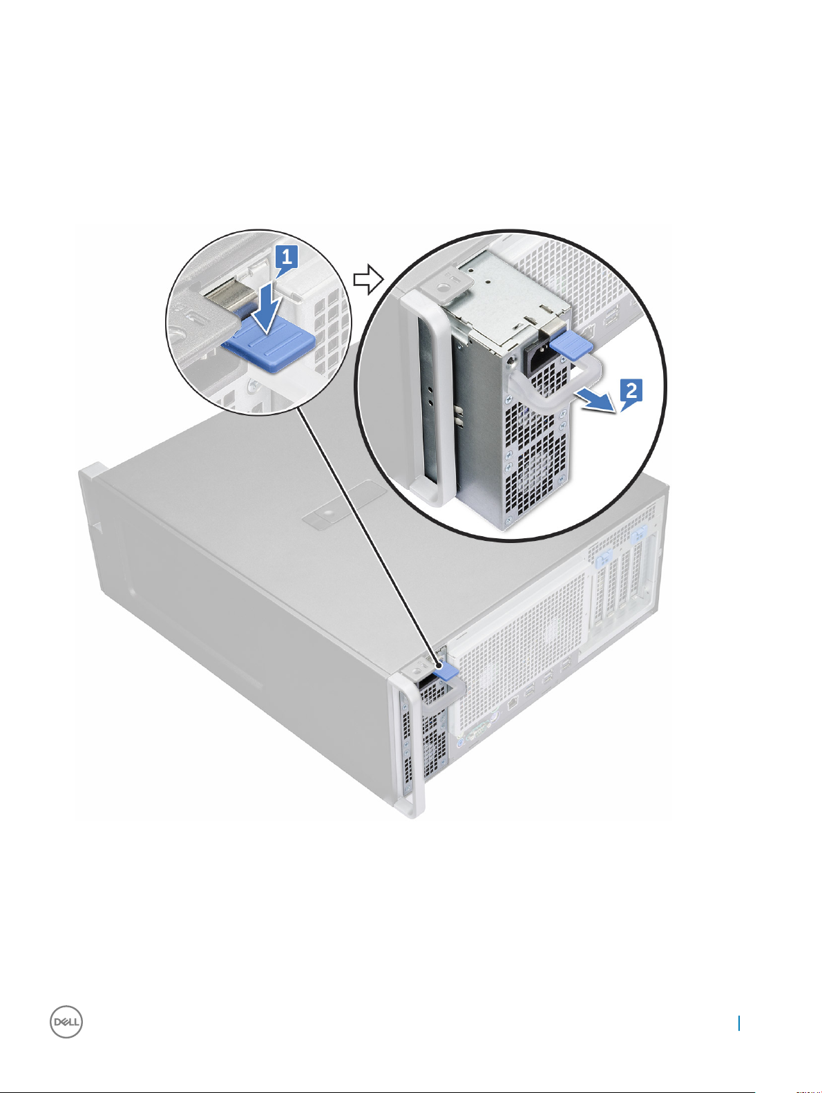
Removing the PSU
1 Follow the procedure in Before working inside your computer.
2 Disconnect the power cable from the system.
3 Press the PSU release latch [1] and slide the power supply away from the system [2].
Installing the PSU
1 Slide in the power supply unit to the PSU slot on the system.
2 Connect the power cable to the system.
3 Follow the procedure in After working inside your computer
Removing and installing components
11
Side cover
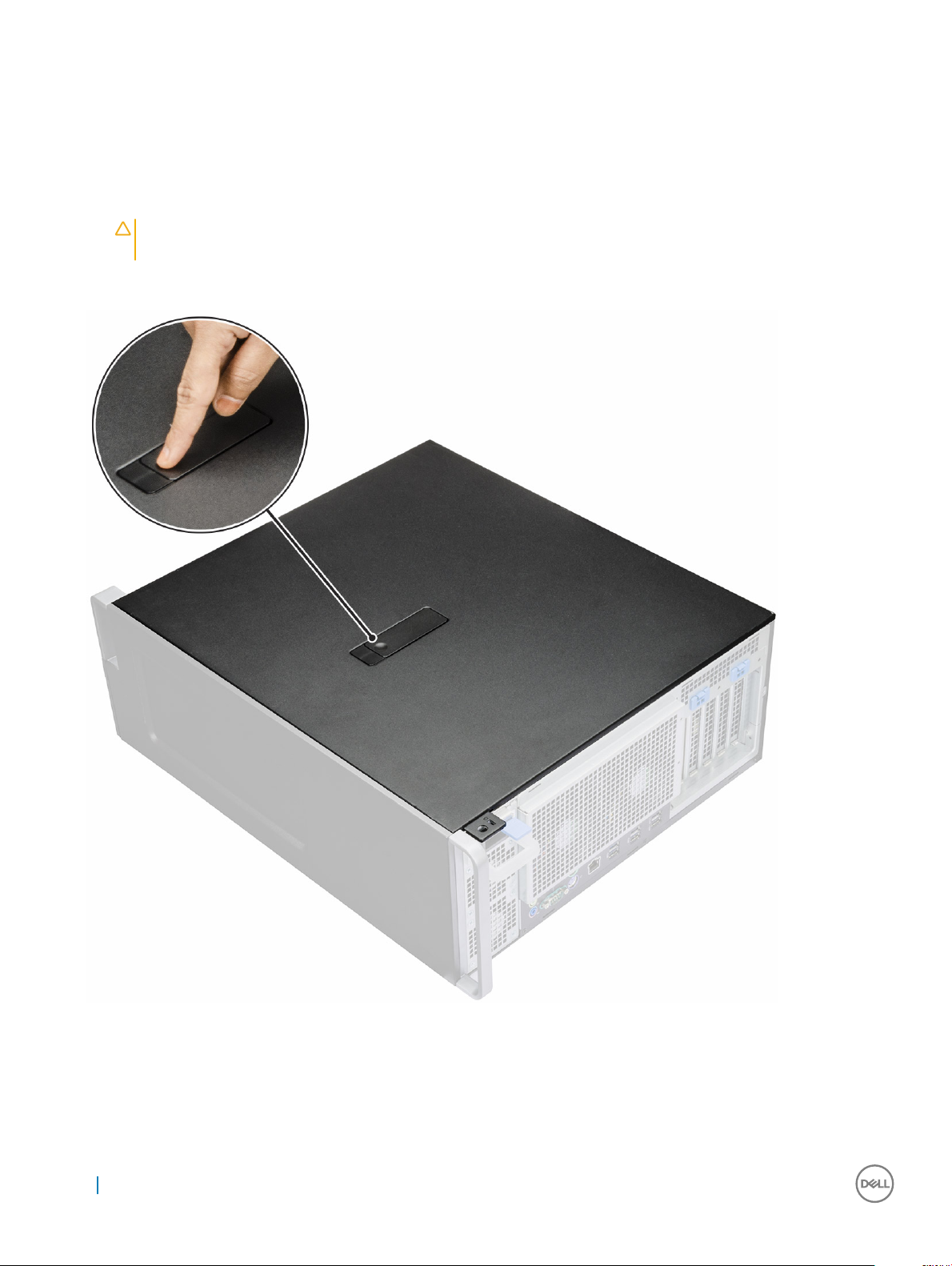
Removing the side cover
1 Follow the procedure in Before working inside your computer.
CAUTION: The system will not power on while the side cover is o. Also, the system will shut down if the side cover is
removed while the system is on.
2 To remove the side cover:
3 Press the latch
4 Pull the latch [1] upward and rotate it to release the cover [2].
12
Removing and installing components
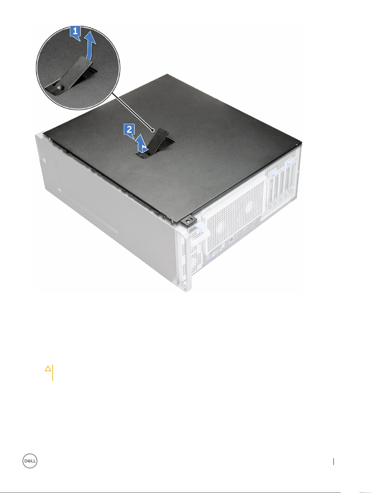
5 Lift the cover to remove it from the system.
Installing the side cover
1 First hold and align the bottom of the side cover to the chassis.
2 Ensure that the hook on the bottom of the side cover snaps into the notch on the system.
3 Press the system cover until it clicks into place.
CAUTION
removed while the system is on.
4 Follow the procedure in After working inside your computer .
: The system will not power on without the side cover. Also, the system will shut down if the side cover is
Removing and installing components
13
Front bezel
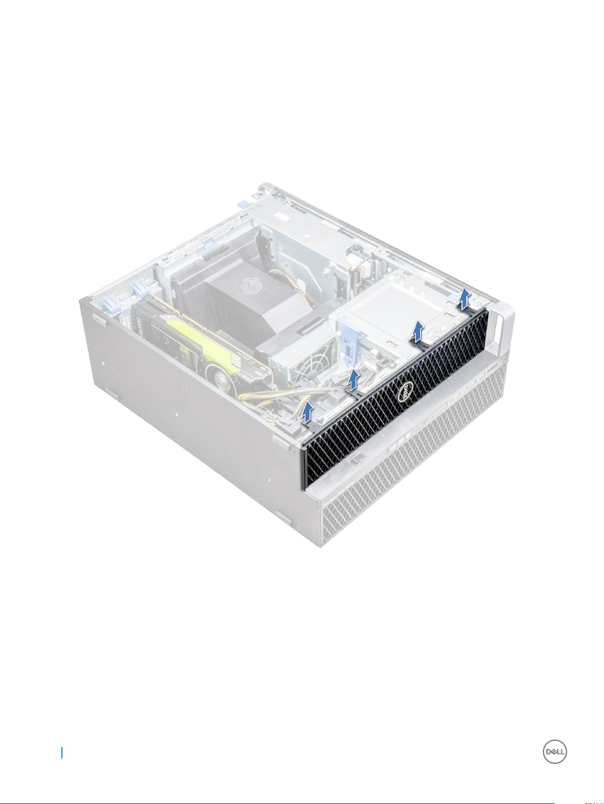
Removing the front bezel
1 Follow the procedure in Before working inside your computer.
2 Remove the side cover.
3 To remove the front bezel:
a Pry the retention tabs to release the front bezel from the system.
b Rotate the bezel forward and lift the front bezel away from the system.
14
Removing and installing components
Installing the front bezel
1 Hold the bezel and ensure that the hooks on the bezel snap into the notches on the system.
2 Rotate the bezel forward and press the front bezel until the tabs click into place.
3 Follow the procedure in After working inside your computer.
Hard Disk Drive bezel
Removing HDD bezel
1 Follow the procedure in Before working inside your computer.
2 Remove the side cover.
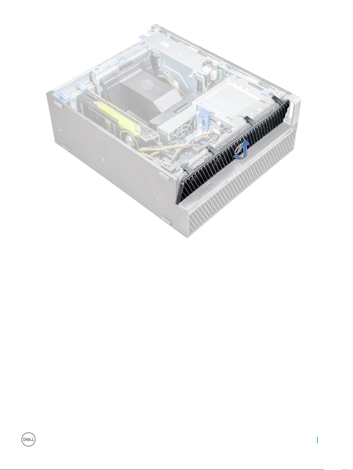
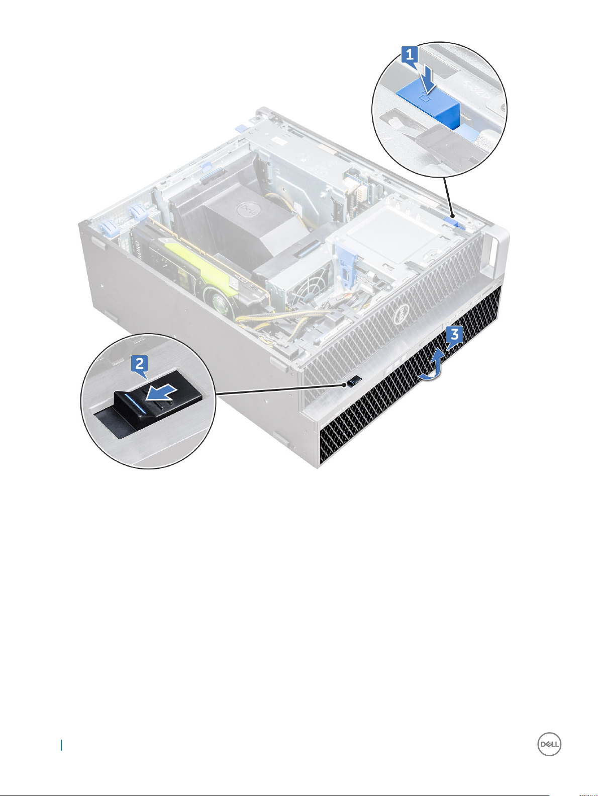
3 To remove the HDD bezel:
a Press the blue unlock button [1] on the edge of ODD bay.
b Slide the latch [2] to the unlock position, on the front I/O bezel.
c Rotate forward and lift the HDD bezel [3] away from the system.
Removing and installing components
15
Installing HDD bezel
1 Hold the bezel and ensure that the hooks on the bezel snap into the notches on the system.
2 Press the blue lock button on the left edge of the ODD bay to secure the bezel to the system.
3 Install the side cover.
4 Follow the procedure in After working inside your computer.
Hard disk drive assembly
Removing the HDD bracket
1 Follow the procedure in Before working inside your computer.
2 Remove the:
a side cover
16
Removing and installing components
NOTE: Do not remove the side cover, if the front I/O bezel is unlocked.
b HDD bezel
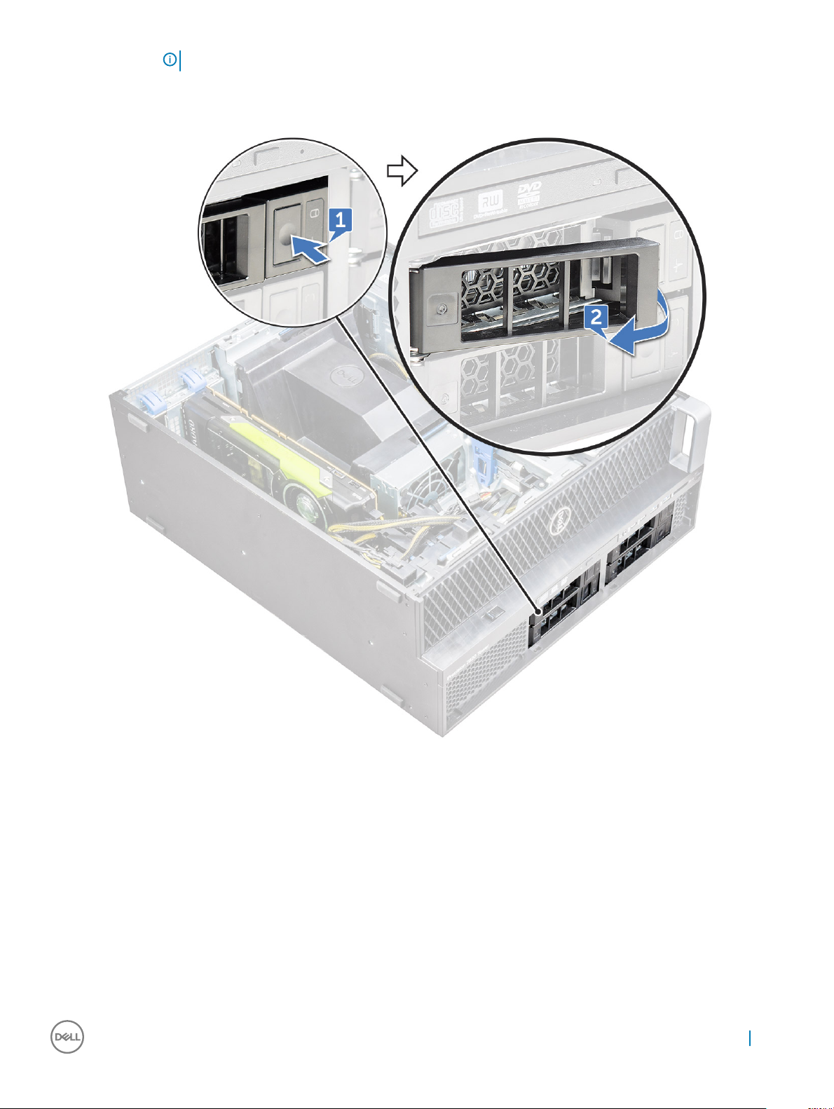
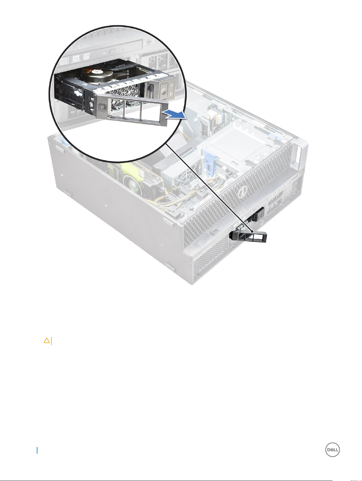
3 To remove the HDD bracket:
a Press the release button [1] to unlock the latch [2].
b Pull the latch to slide the bracket out of the HDD slot.
Removing and installing components
17
Installing the HDD bracket
1 Slide the bracket into the drive bay until it clicks into place.
CAUTION
2 Lock the latch.
3 Install the following components:
a HDD bezel
b side cover
4 Follow the procedure in After working inside your computer.
: Ensure that the latch is open before installing the bracket.
Removing the HDD
1 Follow the procedure in Before working inside your computer.
2 Remove the following:
18
Removing and installing components
a side cover
b HDD bezel
c HDD bracket
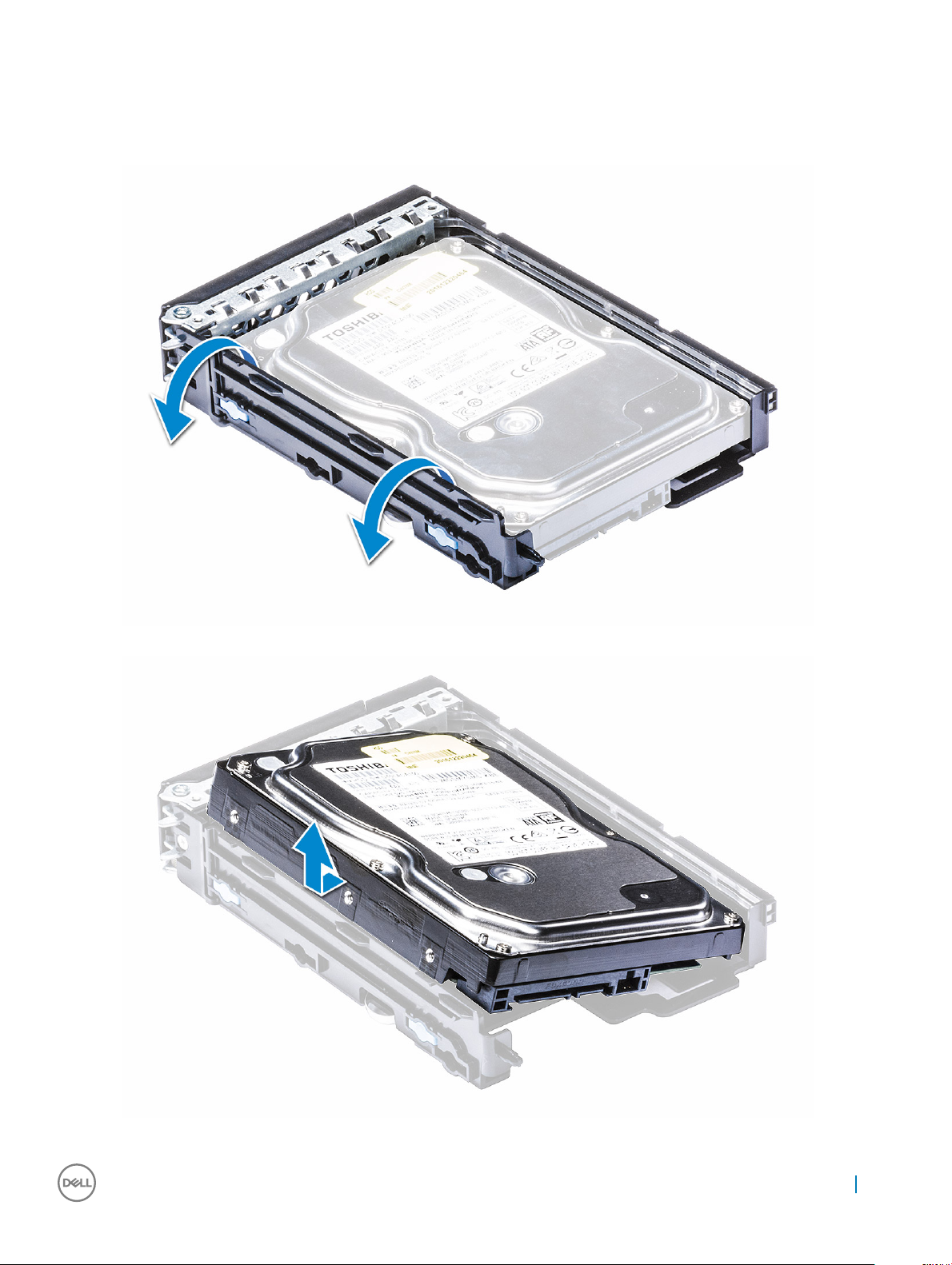
3 To remove the HDD:
a Expand one side of the bracket.
b Lift the hard drive out of the bracket.
Removing and installing components
19

Installing the HDD
1 Insert the HDD into the 3.5" bracket with the connector end of the hard drive towards the back of the HDD bracket.
2 Slide the HDD bracket back into the hard drive bay.
3 Install the following:
a HDD bracket
b HDD bezel
c side cover
4 Follow the procedure in After working inside your computer
Slim Optical Disk Drive
Removing the slim ODD
1 Follow the procedure in Before working inside the computer.
2 Remove the side cover.
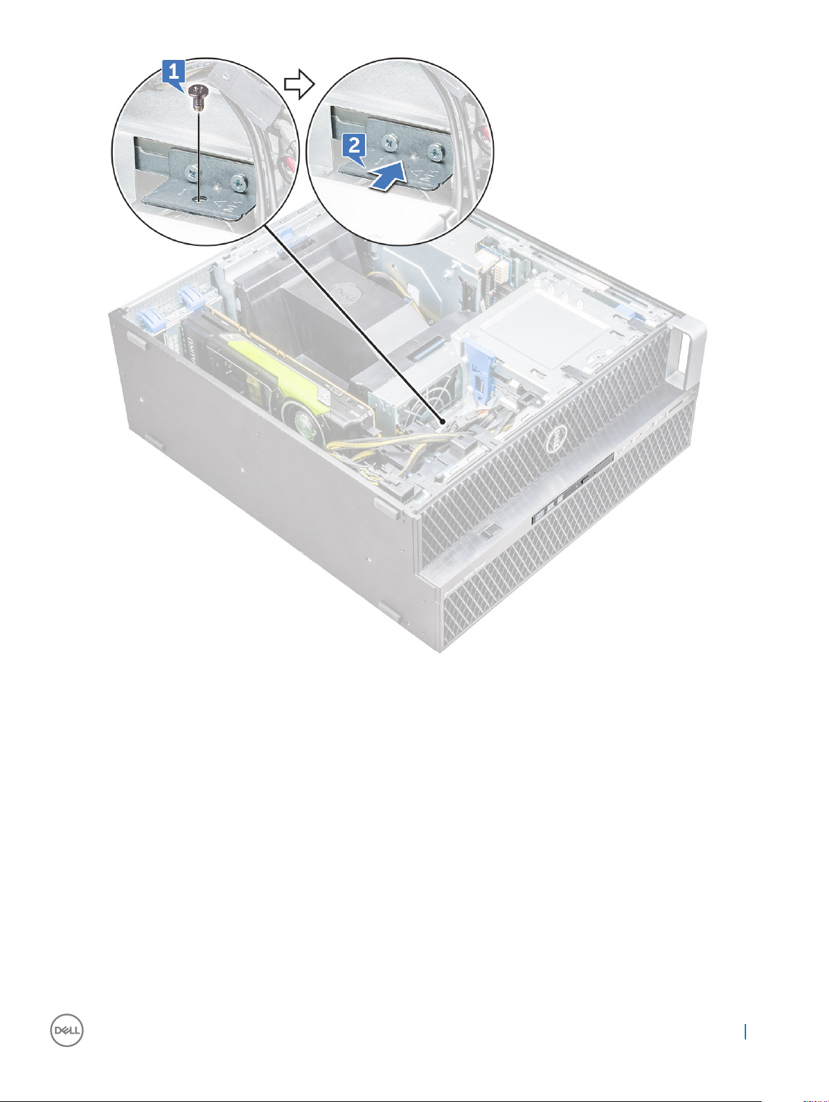
3 To remove the slim ODD:
a Remove the screw [1] that secures the slim ODD and push the slim ODD [2] out of the chassis.
20
Removing and installing components
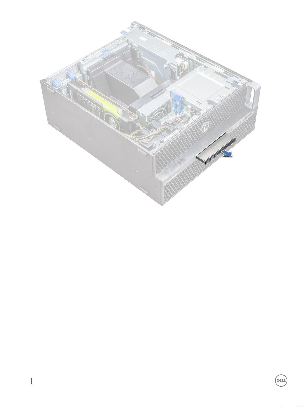
b Slide the slim ODD out of the system.
Removing and installing components
21
Installing the slim ODD
1 Slide the slim ODD into the slot on the chassis.
2 Tighten the screw to secure the slim ODD to the chassis.
3 Install the side cover.
4 Follow the procedure in After working inside your computer.
Front input and output bezel
Removing front input and output bezel
1 Follow the procedure in Before working inside your computer.
2 Remove the:
a side cover
b front bezel
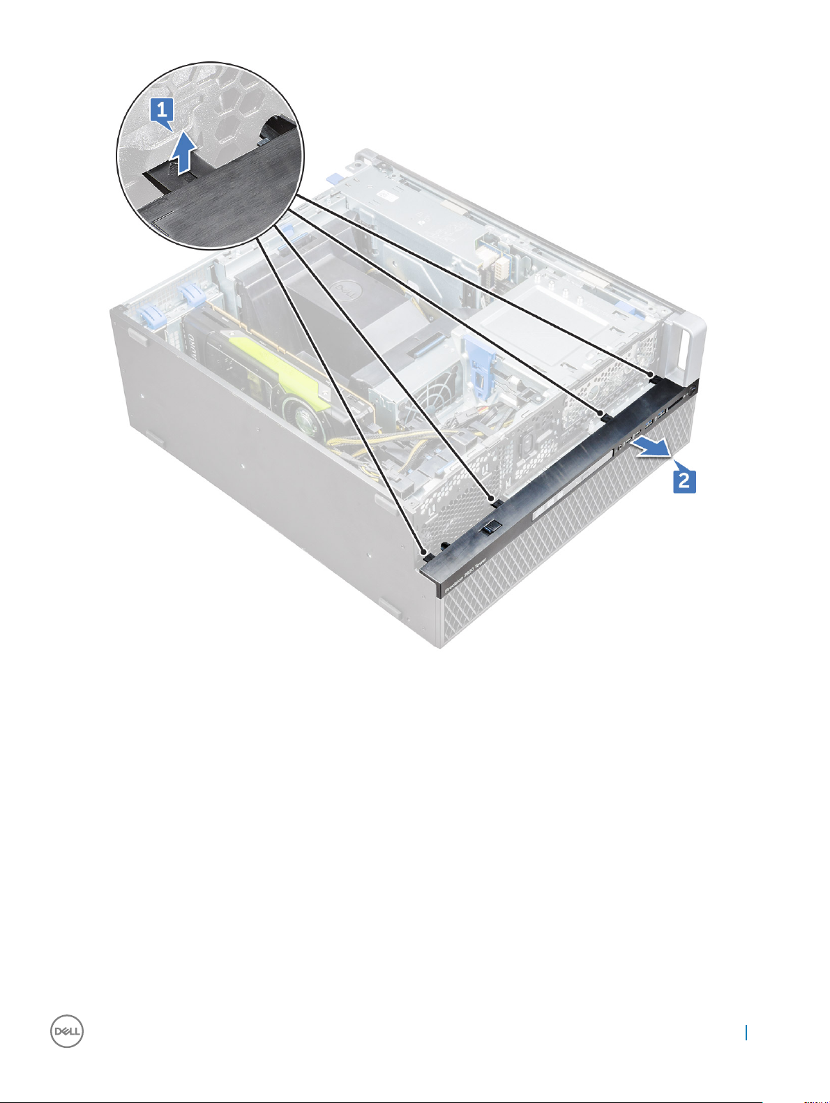
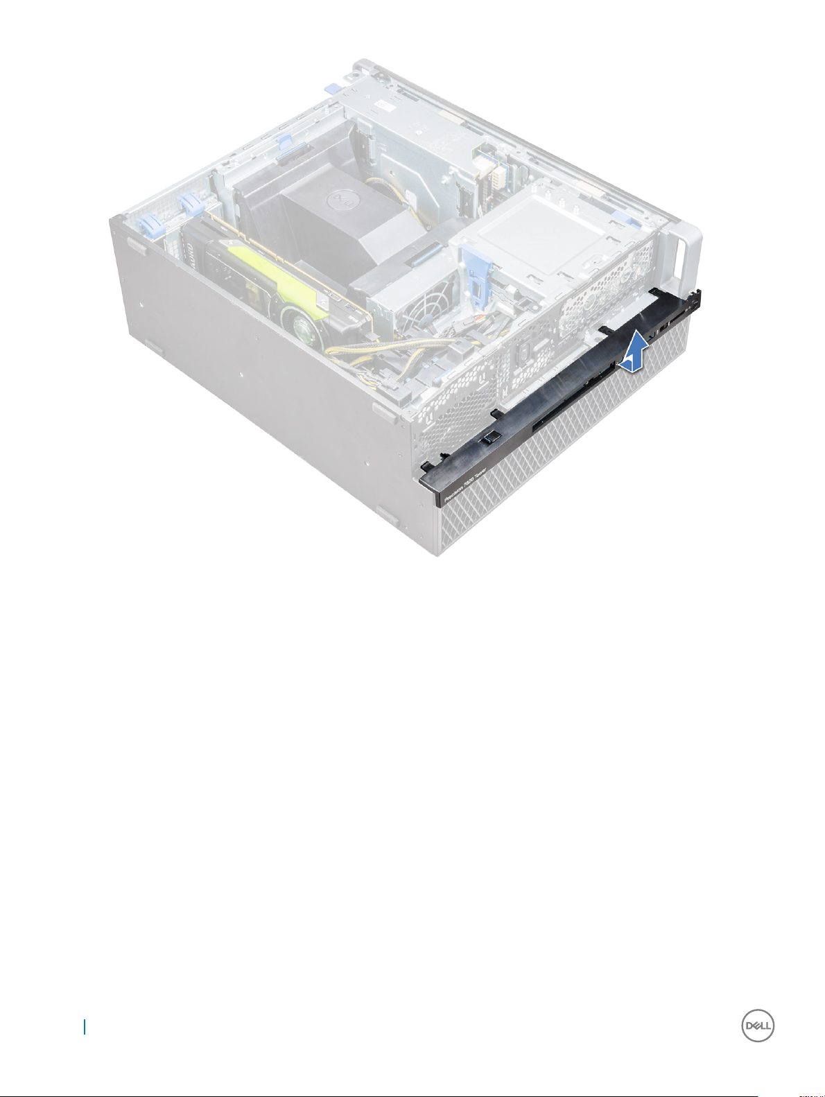
3 To remove the front input and output(I/O) bezel:
a Pry the four retention tabs[1] from the chassis and push the bezel out from the chassis[2].
22
Removing and installing components
b Lift the bezel from the chassis.
Removing and installing components
23
Installing front input and output bezel
1 Hold the input and output(I/O) bezel and ensure that the hooks on the bezel snap into the notches on the system.
2 Press the retention tabs and secure them to the chassis.
3 Install the :
a front bezel
b side cover
4 Follow the procedure in After working inside your computer.
5.25 inch ODD bracket
Removing the 5.25 ODD bracket
1 Follow the procedure in Before working inside your computer.
2 Remove the:
a side cover
b front bezel
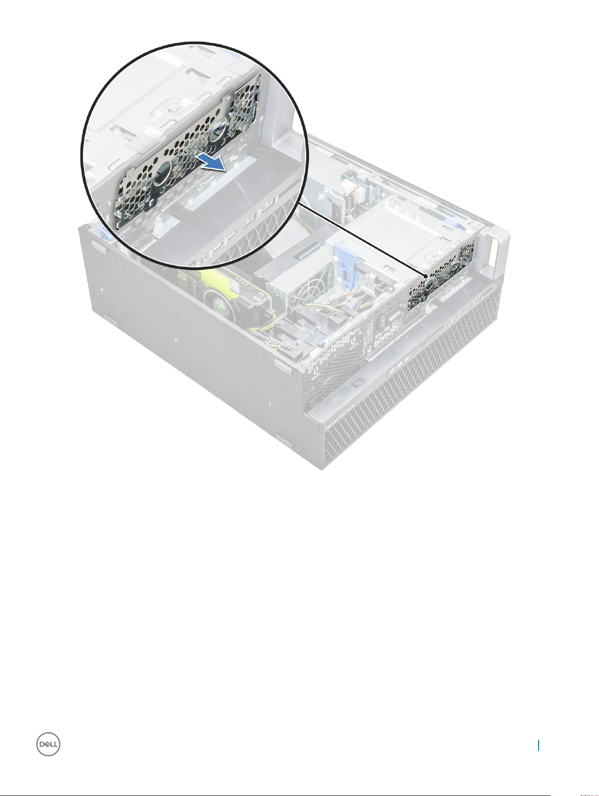
3 To remove the ODD bracket:
a Remove the ODD ller from the chassis.
24
Removing and installing components
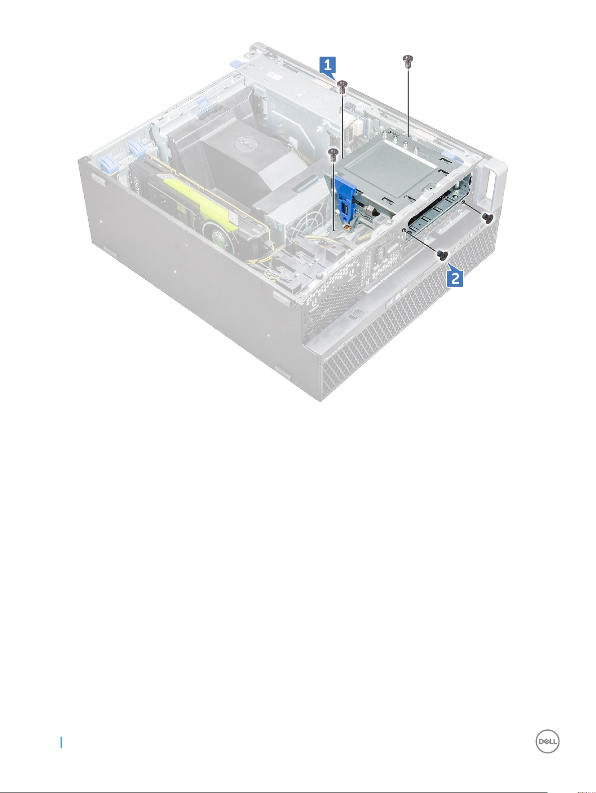
b Remove the ve screws[1,2] that secure the bracket to the chassis.
Removing and installing components
25
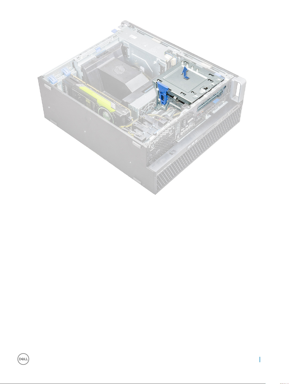
c Slide the ODD bracket toward the rear of the system and lift it away from the chassis.
26
Removing and installing components
Installing the 5.25 ODD bay
1 Place the ODD bracket into the system slot.
2 Replace the (6-32 X 6.0mm) screws.
3 Place the ODD ller back into the slot.
4 Install the:
a front bezel
b side cover
5 Follow the procedure in After working inside your computer
Front input and output panel
Removing front input and output panel
1 Follow the procedure in Before working inside your computer.
2 Remove the:
a side cover
b front bezel
c front input and output bezel
d 5.25 inch ODD bracket
Removing and installing components
27
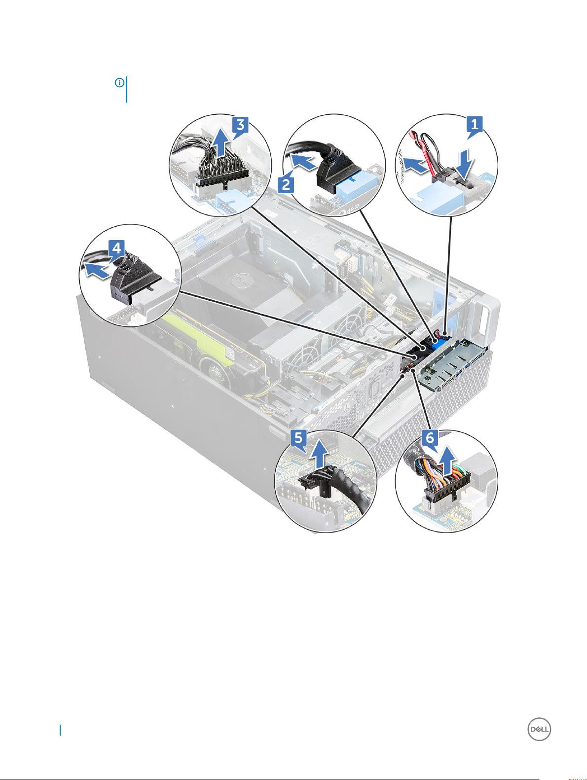
3 To remove the front input and output(I/O) panel:
a Disconnect the intruder switch cable [1], USB 3.1 cable [2], front I/O power cable [3], USB 3.1 cable [4], Speaker cable [5], Audio
cable [6]
NOTE: Do not pull the connector by the cable wires. Instead, disconnect the cable by pulling the connector
end. Pulling the cable wires may loosen them from the connector.
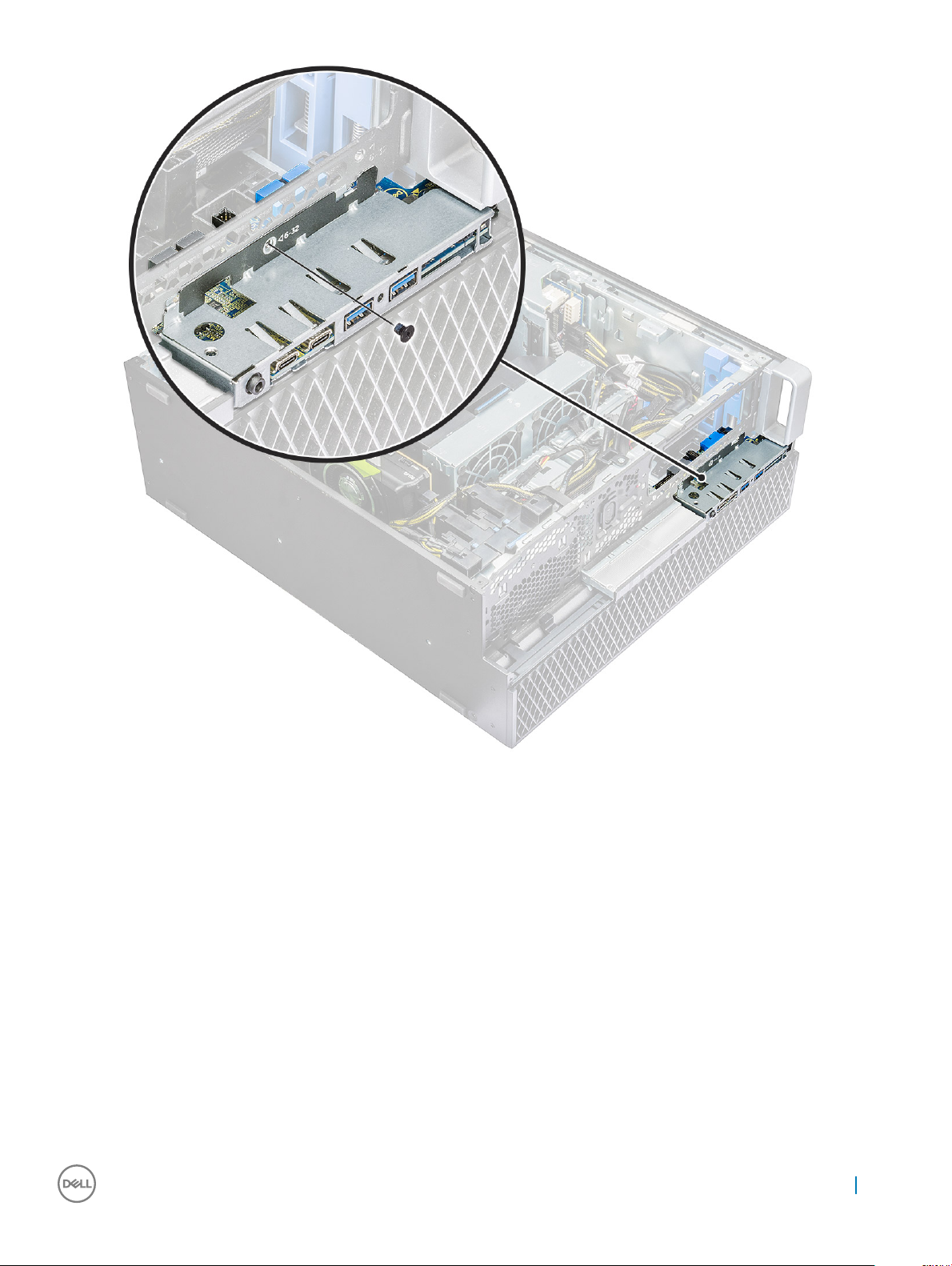
b Remove the screw that secures the front I/O panel to the chassis.
28
Removing and installing components
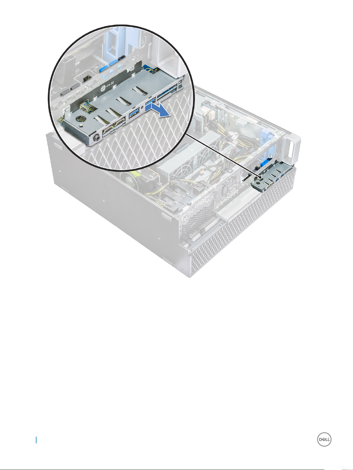
c Slide the I/O panel out of the chassis.
Removing and installing components
29
Installing front input and output panel
1 Insert the input and output(I/O) panel onto its slot in the system.
2 Slide the panel to secure the hooks into the chassis hole.
3 Tighten the screw to secure the front I/O panel to the chassis.
4 Connect the following cables:
• intruder switch cable
• USB 3.1 cable
• front I/O power cable
• front I/O power cable
• USB 3.1 cable
• speaker cable
• audio cable
5 Install the:
a front input and output bezel
b 5.25 inch ODD bracket
30
Removing and installing components
 Loading...