

Dell Precision 370 User Manual

Dell Precision™ Workstation 370 User's Guide
Information About Your Computer
Finding Information
Specifications
Caring for Your Computer
Your Mini-Tower Computer
Front View
Back View
Inside View
System Board Components
Your Desktop Computer
Front View
Back View
Inside View
System Board Components
Advanced Features
LegacySelect Technology Control
Manageability
Security
Password Protection
System Setup
Clearing Forgotten Passwords
Clearing CMOS Settings
Power Management
Hyper-Threading
IEEE 1394
U320 SCSI Controller
About RAID Configurations
Copying CDs and DVDs
How to Copy a CD or DVD
Using Blank CD-Rs and CD-RWs
Helpful Tips
Removing and Installing Parts for Your
Mini- Tower Computer
Before You Begin
Opening the Computer Cover
Memory
Drives
Hard Drive
Front-Panel Inserts
Floppy Drive
CD/DVD Drive
Cards
Installing the Card Fan
Airflow Shroud
Processor
Battery
Control Panel
I/O Panel
Power Supply
Tools to Help Solve
Problems
Diagnostic Lights
Beep Codes
Error Messages
Dell Diagnostics
Drivers
Using Microsoft® Windows® XP
System Restore
Resolving Software and
Hardware Incompatibilities
Reinstalling Microsoft®
Windows® XP
Solving Problems
Troubleshooting Tips
Battery Problems
Card Problems
Card Fan Problems
Drive Problems
E-Mail, Modem, and Internet
Problems
IEEE 1394 Device Problems
Keyboard Problems
Lockups and Software Problems
Memory Problems
Mouse Problems
Network Problems
Power Problems
Printer Problems
Serial or Parallel Device
Problems
Sound and Speaker Problems
Video and Monitor Problems
Cleaning Your
Computer
Computer, Keyboard, and
Monitor
Mouse
Floppy Drive
CDs and DVDs
Features of Windows
XP
Transferring Information to a
New Computer
Switching to Microsoft®
Windows® Classic View
Choosing a Wallpaper
Choosing a Screen Saver
Choosing a Desktop Theme
Creating and Arranging
Shortcuts
Desktop Cleanup Wizard
System Board
Closing the Computer Cover
Removing and Installing Parts for Your
Desktop Computer
Before You Begin
Opening the Computer Cover
Memory
Drives
Hard Drive
Front Panel
Floppy Drive
CD/DVD Drive
Cards
Airflow Shroud
Processor
Battery
Control Panel
I/O Panel
Power Supply
System Board
Closing the Computer Cover
Internet Connection Firewall
Setting Up a Home and Office
Network
Appendix
Getting Help
Technical Assistance
Problems With Your Order
Product Information
Returning Items for Warranty
Repair or Credit
Before You Call
Contacting Dell
Glossary
FCC Notices (U.S.
Only)
Class A
Class B
FCC Identification Information
Notes, Notices, and Cautions
NOTE: A NOTE indicates important information that helps you make better use of your computer.
NOTICE: A NOTICE indicates either potential damage to hardware or loss of data and tells you how to avoid the
problem.
CAUTION: A CAUTION indicates a potential for property damage, personal injury, or death.
Abbreviations and Acronyms
For a complete list of abbreviations and acronyms, see the Glossary.
If you purchased a Dell™ n Series computer, any references in this document to Microsoft® Windows® operating systems are
not applicable.
Information in this document is subject to change without notice.
© 2004 Dell Inc. All rights reserved.
Reproduction in any manner whatsoever without the written permission of Dell Inc. is strictly forbidden.
Trademarks used in this text: Dell, the DELL logo, Dell Precision , Dimension, OptiPlex, Inspiron, Latitude, PowerApp, PowerConnect, PowerVault,
Axim, and DellNet are trademarks of Dell Inc.; Intel and Pentium are registered trademark of Intel Corporation; Microsoft, Windows, and MS-DOS
are registered trademarks of Microsoft Corporation.
Other trademarks and trade names may be used in this document to refer to either the entities claiming the marks and names or their products.
Dell Inc. disclaims any proprietary interest in trademarks and trade names other than its own.
Model DHM and WHM
April 2004 P/N U3526 Rev. A00
Back to Contents Page
Information About Your Computer
Dell Precision™ Workstation 370 User's Guide
Finding Information
Specifications
Caring for Your Computer
Finding Information
What Are You Looking For? Find it Here
A diagnostic program
for my computer
Drivers for my
computer
My computer
documentation
My device
documentation
Desktop System
Software (DSS)
How to set up my
computer
How to care for my
computer
Troubleshooting
information
How to run the Dell
Diagnostics
Error codes and
diagnostic lights
How to open my
computer cover
Drivers and Utilities CD (also known as the ResourceCD)
Documentation and drivers are already installed on your computer. You can use the CD to
reinstall drivers, run the Dell Diagnostics
Readme files may be included on your CD to provide lastminute updates about technical changes to your computer or advanced technical-reference
material for technicians or experienced users.
NOTE: The latest drivers and documentation updates can be found at support.dell.com.
, or access your documentation.
Quick Reference Guide
System board
connectors
Location of system
board components
NOTE: This document is available as a PDF at support.dell.com.
System Information Label
Located on the inside cover of your computer.
Warranty information
Safety instructions
Regulatory information
Ergonomics information
End User License
Agreement
Dell™ Product Information Guide
NOTE: This document is available as a PDF at support.dell.com.
How to remove and
replace parts
Technical specifications
How to configure
system settings
How to troubleshoot
and solve problems
Service Tag and
Express Service Code
Microsoft Windows
License Label
Latest drivers for my
computer
Answers to technical
service and support
questions
Online discussions with
other users and
technical support
Documentation for my
computer
Precision User's Guide
Microsoft® Windows® XP Help and Support Center
1. Click the Start button and click Help and Support.
2. Click User's and system guides and click User's guides.
The User's Guide is also available on the Drivers and Utilities CD.
Service Tag and Microsoft Windows License
These labels are located on your computer.
Use the Service Tag to identify your computer when you use support.dell.com or
contact technical support.
Enter the Express Service Code to direct your call when contacting technical support.
The Express Service Code is not available in all countries.
Dell Support Website — support.dell.com
NOTE: Select your region to view the appropriate support site.
The Dell Support website provides several online tools, including:
Solutions — Troubleshooting hints and tips, articles from technicians, and online
courses
Community — Online discussion with other Dell customers
Upgrades — Upgrade information for components, such as memory, the hard drive,
and the operating system
Customer Care — Contact information, order status, warranty, and repair
information
Downloads — Drivers, patches, and software updates
Reference — Computer documentation, product specifications, and white papers
Service call status and
support history
Top technical issues for
my computer
Frequently asked
questions
File downloads
Details on my computer
configuration
Service contract for my
computer
How to use Windows XP
Documentation for my
computer
Documentation for
devices (such as a
modem)
How to use Linux
Email discussions with
Dell Precision and Linux
users
Additional information
regarding Linux and my
Dell Precision computer
Dell Premier Support Website — premiersupport.dell.com
The Dell Premier Support website is customized for corporate, government, and education
customers. This website may not be available in all regions.
Windows Help and Support Center
1. Click the Start button and click Help and Support.
2. Type a word or phrase that describes your problem and click the arrow icon.
3. Click the topic that describes your problem.
4. Follow the instructions on the screen.
Dell Supported Linux Sites
http://linux.dell.com
http://lists.us.dell.com/mailman/listinfo/linux-precision
http://docs.us.dell.com/docs/software/oslinux/
http://docs.us.dell.com/docs/software/OSRHEL3/
How to reinstall my
operating system
Operating System CD
The operating system is already installed on your computer. To reinstall your operating
system, use the Operating System CD. See your Precision User's Guide for instructions.
After you reinstall your operating system, use the Drivers and Utilities CD to reinstall
drivers for the devices that came with your computer.
Your operating system product key
NOTE: The color of your CD varies based on the operating system you ordered.
label is located on your computer.
Specifications
Microprocessor
Microprocessor type
Intel® Pentium
Technology Extreme Edition
or Intel® Pentium
®
4 Processor with HT
®
4 Processor with HT
Technology
Level 1 (L1) cache 8 KB or 16 KB
Level 2 (L2) cache 512 KB or 1 MB
Level 3 (L3) cache 0 or 2 MB
Memory
Type Dual channel DDR2 400-MHz (PC2-3200)
non-ECC and 533-MHz (PC2–4300) ECC
SDRAM.
NOTE: Ensure that you do not mix ECC
and non-ECC memory.
NOTE: Your computer does not support
registered or buffered memory
Memory connectors 4
Memory capacities 128-, 256-, 512-, or 1-GB
Minimum memory 256 MB
Maximum memory 4 GB
BIOS address F0000h
Computer Information
Chipset Intel 925X Express
Data bus width 64 bits
Address bus width 32 bits
DMA channels eight
Interrupt levels 24
BIOS chip (NVRAM) 4-Mb
Memory speed 400/533 MHz
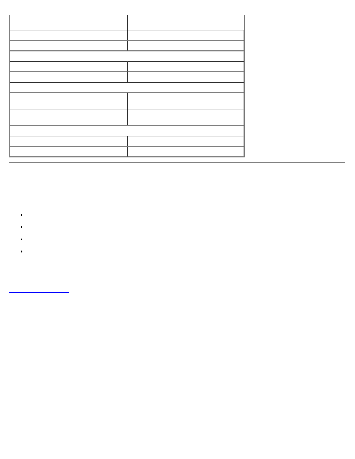
NIC Integrated network interface with ASF 1.0
support as defined by DMTF
Capable of 10/100/1000 communication
Green — A good connection exists
between a 10-Mbps network and
the computer.
Orange — A good connection exists
between a 100-Mbps network and
the computer.
Yellow — A good connection exists
between a 1 Gb (or 1000-Mbps)
connection.
Off — The computer is not
detecting a physical connection to
the network.
SCSI controller add-in U320 SCSI
System clock 800 MHz data rate
Video
Type PCI Express x16 up to 150 W
Audio
Type AC97, Sound Blaster emulation
Stereo conversion 16-bit analog-to-digital; 20-bit digital-to-
analog
Controllers
Hard drive Integrated Serial ATA (4), with RAID 0/1
& Command Queuing
Integrated ATA-100 (1 channel)
Expansion Bus
Bus type mini-tower computer: 3 PCI 2.3 5v
desktop computer: 4 PCI 2.3 5v
one PCI Express x16 up to 150W
one PCI Express x1
eight USB 2.0 (2 front, 6 back)
Bus speed PCI: 33 MHz
PCI
connectors mini-tower computer: three
connector size 120 pins
connector data width (maximum) 32 bits
PCI Express
connectors one x1
connector size 36 pins
connector data width (maximum) 1 PCI Express lane
PCI Express
connectors one x16
connector size 164 pins
PCI Express:
x1 slot bidirectional speed - 500
MB/s
x16 slot bidirectional speed - 8
GB/s
desktop computer: four
connector data0 width (maximum) 16 PCI Express lanes
Drives
Externally accessible:
Desktop computer one 3.5 inch drive bay (for optional
Mini-tower computer two 3.5 inch drive bays
floppy)
two 5.25-inch bays
two 5.25-inch drive bays
Available devices Serial ATA drive, floppy drive, USB
memory devices, CD drive, CD-RW drive,
DVD drive, DVD+RW drive, and DVD and
CD-RW combo drive
Internally accessible:
Connectors
External connectors:
Serial one 9-pin connector (optional 2nd
Parallel one 25-hole connector (bidirectional)
IEEE 1394 6-pin serial connector (add-in card)
Video 15-hole connector
Network adapter RJ45 connector
PS/2 (keyboard and mouse) 6-pin mini-DIN
USB two front-panel and six back-panel USB
Audio three connectors for line-in, line-out, and
I/O panel 34-pin connector
CD drive audio interface 4-pin connector
two bays for 1-inch high hard drives
connector); 16550C-compatible
2.0–compliant connectors
microphone; one front-panel connector
for headphones
Power_1 connector 24-pin connector
System board connectors:
Primary IDE drive 40-pin connector on PCI local bus
Serial ATA (4) 7-pin connector
Fan 5-pin connector
PCI 2.3 120-pin connector
CD drive audio interface 4-pin connector
Key Combinations
<Ctrl><Alt><Del> launches the task manager
<F2> starts embedded system setup (during
start-up only)
<F12> or <Ctrl><Alt><F8> boots from the network (during start-up
only)
<Ctrl><Alt><F10> launches the utility partition (if installed)
during computer start-up
<Ctrl><Alt><D> launches the hard-drive diagnostics utility
during computer start-up
Controls and Lights
Power control push button
Power light green light—blinking green in sleep state;
solid green for power-on state
amber light—blinking amber indicates a
problem with an installed device; solid
amber indicates an internal power
problem (see "Power Problems
Hard-drive access light green
").
Link integrity light (on integrated network
adapter)
Activity light (on integrated network
adapter)
Diagnostic lights four lights on back panel of mini-tower
Standby power light AUX_PWR on the system board
Power
DC power supply:
Wattage 350 W
Heat dissipation 910 BTU/hr
Voltage fixed-voltage power supply—110 V at
Backup battery 3-V CR2032 lithium coin cell
green light for 10-Mb operation; orange
light for 100-Mb operation; yellow light
for a 1000-Mb (1-Gb) operation
yellow blinking light
and front of desktop
50/60 Hz
manual selection and auto-sensing power
supplies—90 to 135 V at 50/60 Hz; 180 to
265 V at 50/60 Hz; 100 V at 50/60 Hz for
Japanese computers
Physical
Mini-tower computer:
Height 42.5 cm (16.8 inches)
Width 19.1 cm (7.5 inches)
Depth 45.0 cm (17.7 inches)
Weight 12.7 kg (28 lbs)
Desktop computer:
Height 16.5 cm (6.5 inches)
Width 44.5 cm (17.5 inches)
Depth 45.7 cm (18 inches)
Weight 18.6 cm (41 lbs)
Supported monitor weight (in
desktop orientation)
Environmental
Temperature:
Operating 10° to 35°C (50° to 95°F)
45.4 kg (100 lbs)
NOTE: At 35°C (95°F), the maximum
operating altitude is 914 m (3000 ft).
Storage –40° to 65°C (–40° to 149°F)
Relative humidity 20% to 80% (noncondensing)
Maximum vibration:
Operating 0.25 G at 3 to 200 Hz at 0.5 octave/min
Storage 0.5 G at 3 to 200 Hz at 1 octave/min
Maximum shock:
Operating bottom half-sine pulse with a change in
velocity of 20 inches/sec (50.8 cm/sec)
Storage 27-G faired square wave with a velocity
change of 200 inches/sec (508 cm/sec)
Altitude:
Operating –15.2 to 3048 m (–50 to 10,000 ft)
Storage –15.2 to 10,668 m (–50 to 35,000 ft)
Caring for Your Computer
To help maintain your computer, follow these suggestions:
To avoid losing or corrupting data, never turn off your computer when the hard drive light is on.
Schedule regular virus scans using virus software.
Manage hard drive space by periodically deleting unnecessary files and defragmenting the drive.
Back up files on a regular basis.
Periodically clean your monitor screen, mouse, and keyboard (see "Cleaning Your Computer
Back to Contents Page
").

Back to Contents Page
Your Mini-Tower Computer
Dell Precision™ Workstation 370 User's Guide
Front View
Back View
Inside View
System Board Components
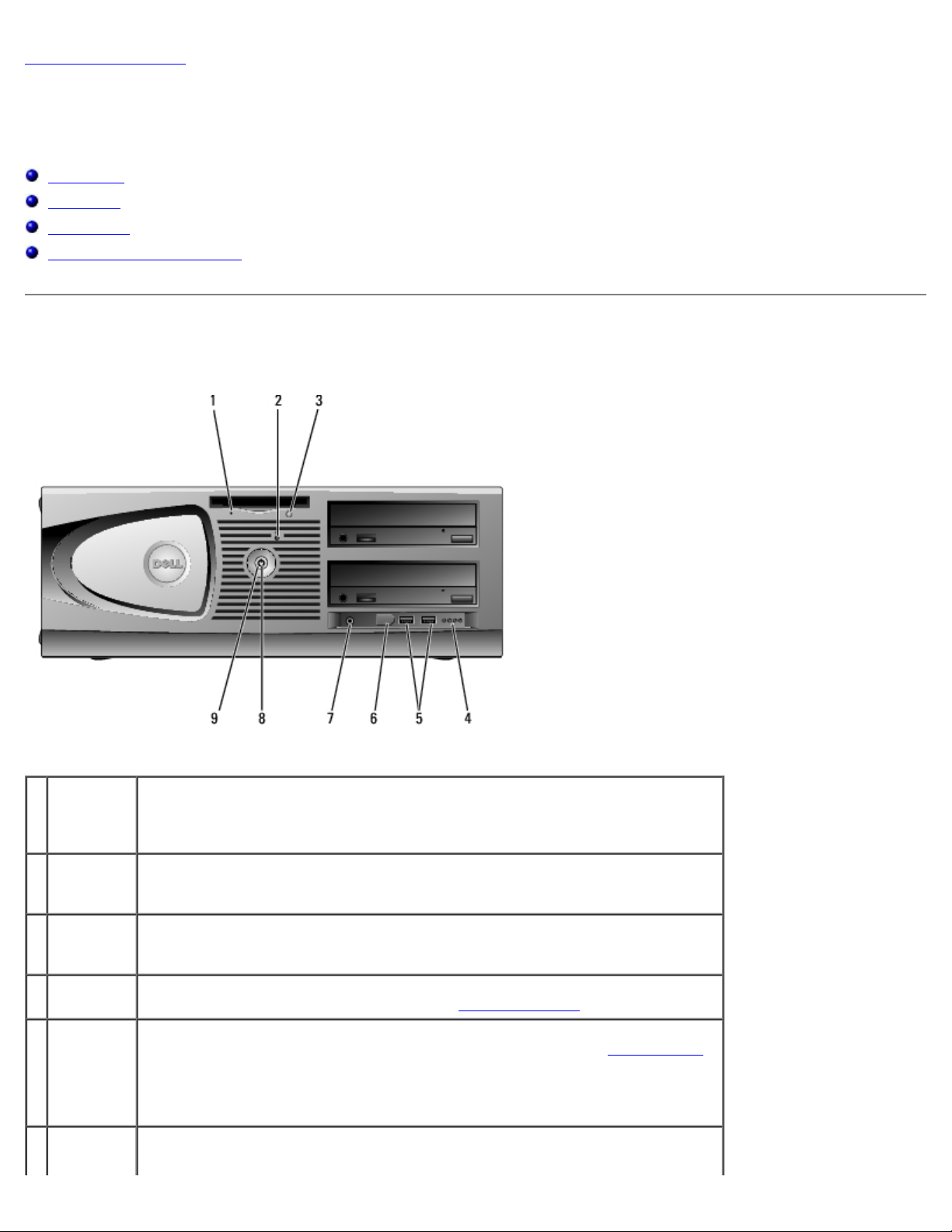
Front View
1 CD or DVD
drive eject
button
2 floppy-
drive
activity
light
3 floppy-
drive eject
button
4 hard-drive
activity
Press to eject a disc from the CD or DVD drive.
The floppy drive light is on when the computer reads data from or writes data
to the floppy drive. Wait until this light turns off before you remove the floppy
disk from the drive.
Press to eject a floppy disk from the floppy drive.
The hard drive light is on when the computer reads data from or writes data to
the hard drive. The light might also be on when a device such as your CD player

light is operating.
5 USB 2.0
connectors
(2)
6 headphone
connector
7 power
light
8 power
button
Use the front USB connectors for devices that you connect occasionally, such as
flash memory keys or cameras, or for bootable USB devices (see system setup
for more information on booting to a USB device).
It is recommended that you use the back USB connectors for devices that
typically remain connected, such as printers and keyboards.
Use the headphone connector to attach headphones and most kinds of
speakers.
The power light illuminates and blinks or remains solid to indicate different
states:
No light — The computer is turned off.
Steady green — The computer is in a normal operating state.
Blinking green — The computer is in a power-saving state.
Blinking or solid amber — See "Power Problems."
To exit from a power-saving state, press the power button or use the keyboard
or the mouse if it is configured as a wake device in the Windows Device
Manager. For more information about sleep states and exiting from a powersaving state, see "Power Management
See "Diagnostic Lights
troubleshoot problems with your computer.
Press to turn on the computer.
NOTE: The power button can also be used to wake the system or to place it
into a power-saving state. See "Power Management
" for a description of light codes that can help you
."
" for more information.
NOTICE: To avoid losing data, do not use the power button to turn off the
computer. Instead, perform an operating system shutdown.
Back View
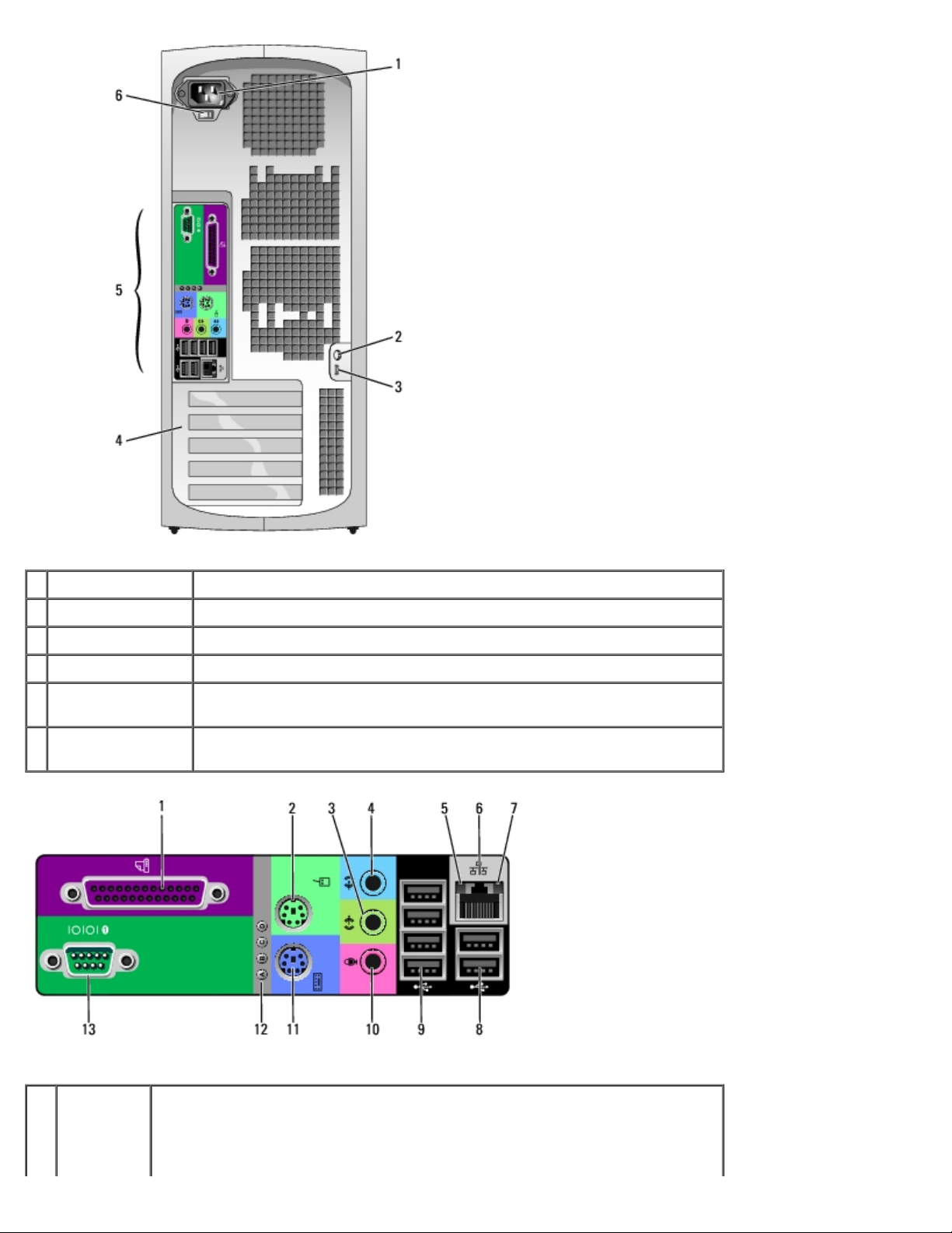
1 power connector Insert the power cable.
2 padlock ring Insert a padlock to lock the computer cover.
3 security cable slot Use a security cable with the slot to help secure your computer.
4 card slots Access connectors for any installed PCI or PCI Express cards.
5 back panel
connectors
6 voltage selection
switch
1 parallel
connector
Connect a parallel device, such as a printer, to the parallel connector. If you
have a USB printer, plug it into a USB connector.
NOTE: The integrated parallel connector is automatically disabled if the
computer detects an installed card containing a parallel connector configured
Plug serial, USB, and other devices into the appropriate connector.
See the safety instructions located in the Product Information Guide for
more information.
to the same address. For more information, see "System Setup Options."
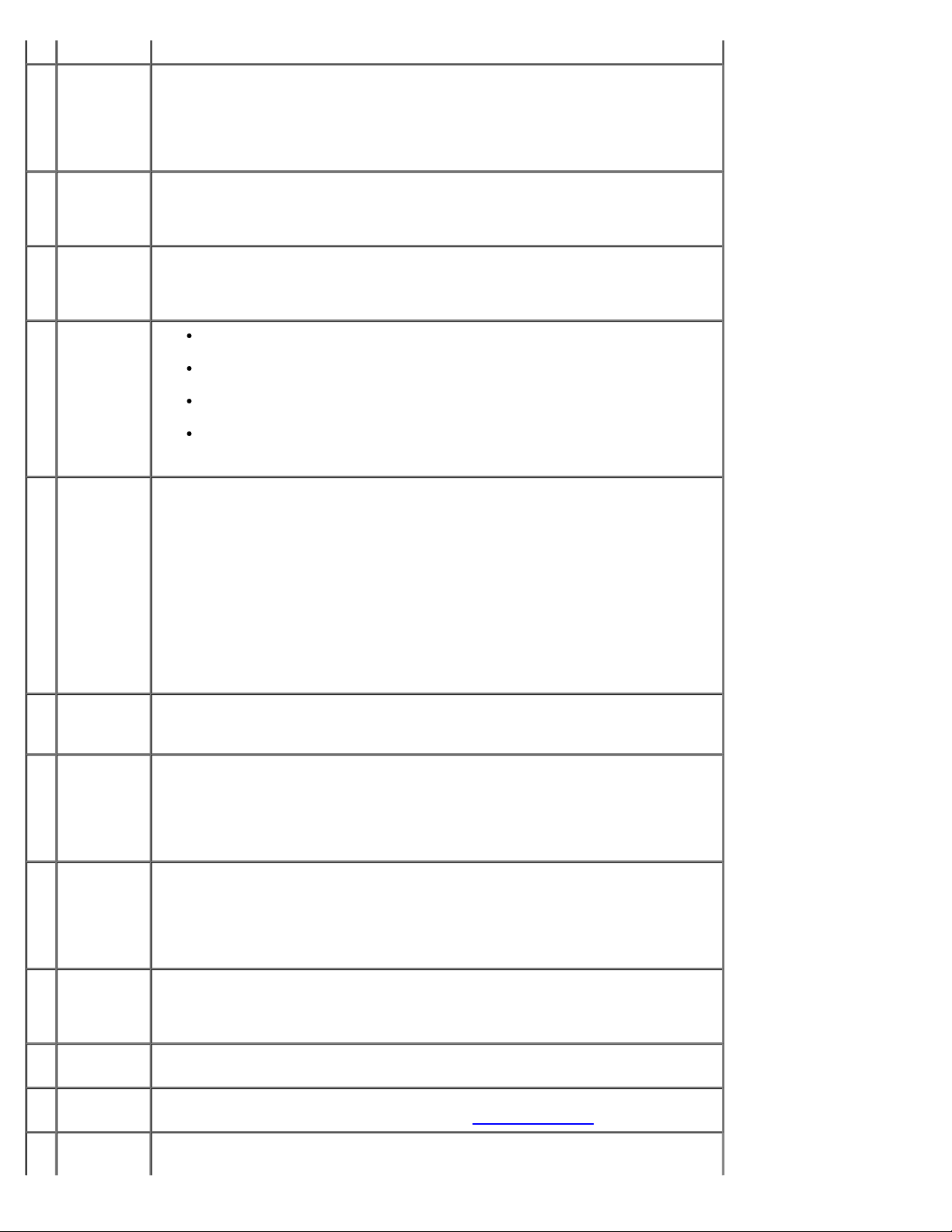
2 mouse
connector
3 line-out
connector
4 line-in
connector
5 link
integrity
light
6 network
adapter
connector
Plug a standard mouse into the green mouse connector. Turn off the computer
and any attached devices before you connect a mouse to the computer. If you
have a USB mouse, plug it into a USB connector.
If your computer is running the Microsoft® Windows XP operating system, the
necessary mouse drivers have been installed on your hard drive.
Use the green line-out connector to attach headphones and most speakers
with integrated amplifiers.
On computers with a sound card, use the connector on the card.
Use the blue line-in connector to attach a record/playback device such as a
cassette player, CD player, or VCR.
On computers with a sound card, use the connector on the card.
Green — A good connection exists between a 10-Mbps network and the
computer.
Orange — A good connection exists between a 100-Mbps network and
the computer.
Yellow — A good connection exists between a 1000-Mbps (or 1-Gbps)
network and the computer.
Off — The computer is not detecting a physical connection to the
network.
To attach your computer to a network or broadband device, connect one end
of a network cable to either a network jack or your network or broadband
device. Connect the other end of the network cable to the network adapter
connector on your computer. A click indicates that the network cable has been
securely attached.
7 network
activity
light
8 USB 2.0
connectors
(2)
9 USB 2.0
connectors
(4)
10 microphone
connector
NOTE: Do not plug a telephone cable into the network connector.
On computers with a network connector card, use the connector on the card.
It is recommended that you use Category 5 wiring and connectors for your
network. If you must use Category 3 wiring, force the network speed to 10
Mbps to ensure reliable operation.
Flashes a yellow light when the computer is transmitting or receiving network
data. A high volume of network traffic may make this light appear to be in a
steady "on" state.
Use the back USB connectors for devices that typically remain connected,
such as printers and keyboards.
It is recommended that you use the front USB connectors for devices that you
connect occasionally, such as flash memory keys or cameras., or for bootable
USB devices.
Use the back USB connectors for devices that typically remain connected,
such as printers and keyboards.
It is recommended that you use the front USB connectors for devices that you
connect occasionally, such as flash memory keys or cameras, or for bootable
USB devices.
Use the pink microphone connector to attach a personal computer microphone
for voice or musical input into a sound or telephony program.
On computers with a sound card, the microphone connector is on the card.
11 keyboard
connector
12 diagnostic
lights (4)
13 serial
connector
If you have a standard keyboard, plug it into the purple keyboard connector.
If you have a USB keyboard, plug it into a USB connector.
Use the lights to help you troubleshoot a computer problem based on the
diagnostic code. For more information, see "Diagnostic Lights
Connect a serial device, such as a handheld device, to the serial port. The
default designations are COM1 for serial connector 1 and COM2 for the
."
optional serial connector 2.
For more information, see "System Setup Options
."
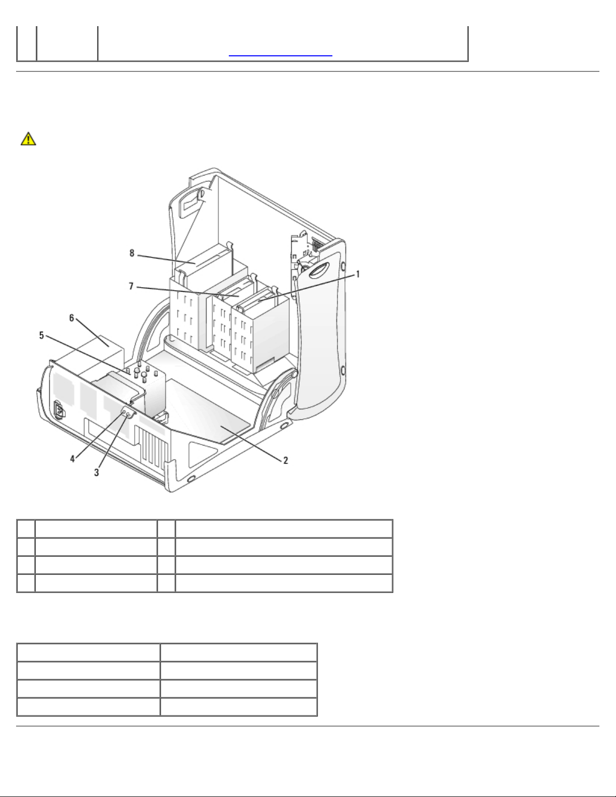
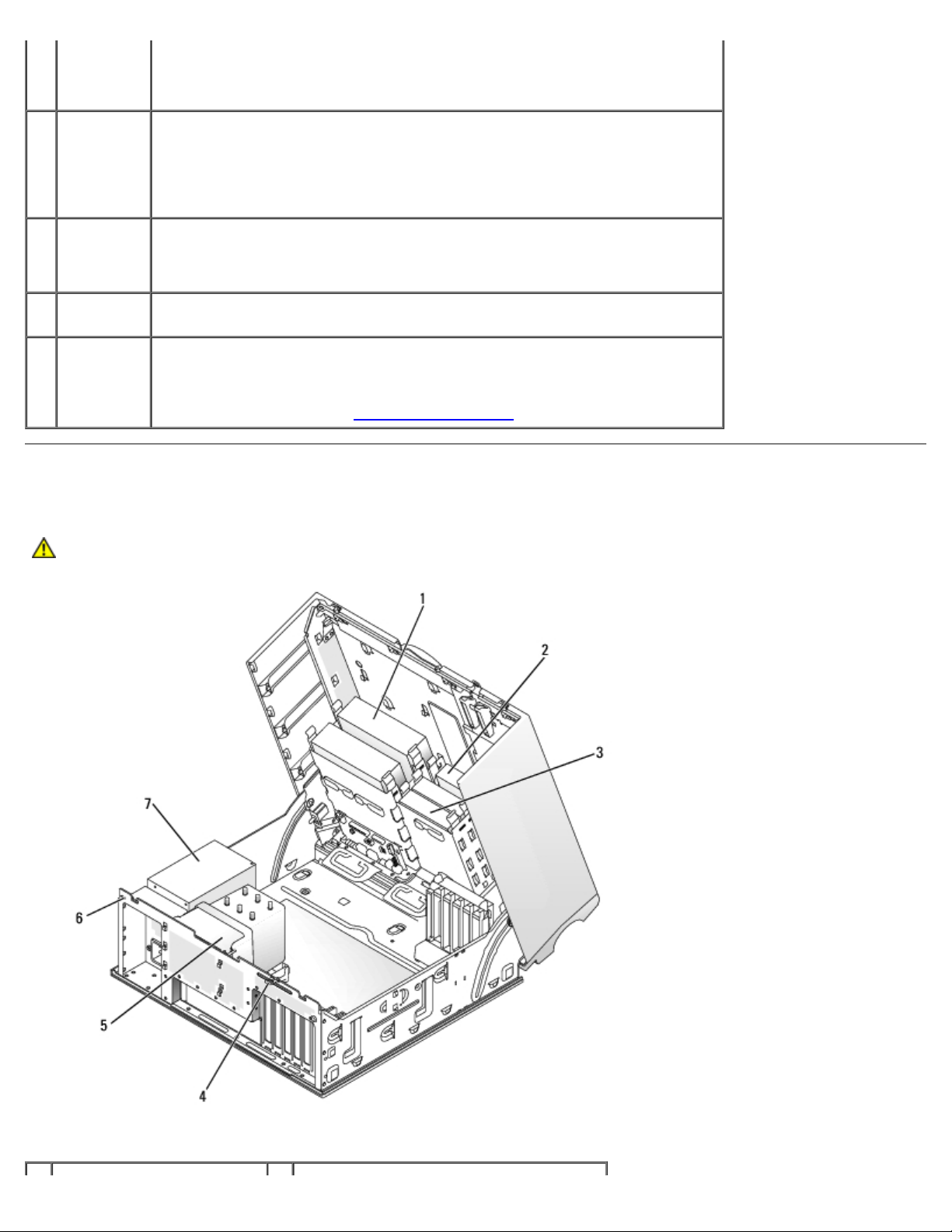
Inside View
CAUTION: Before you begin any of the procedures in this section, follow the safety instructions located in
the Product Information Guide.
1 hard drive 5 processor airflow shroud and fan
2 system board 6 power supply
3 padlock ring 7 floppy drive (optional)
4 security cable slot 8 CD/DVD drive
Cable Colors
Device Color
Hard drive Blue cable
Floppy drive Black pull tab
CD/DVD drive Orange pull tab
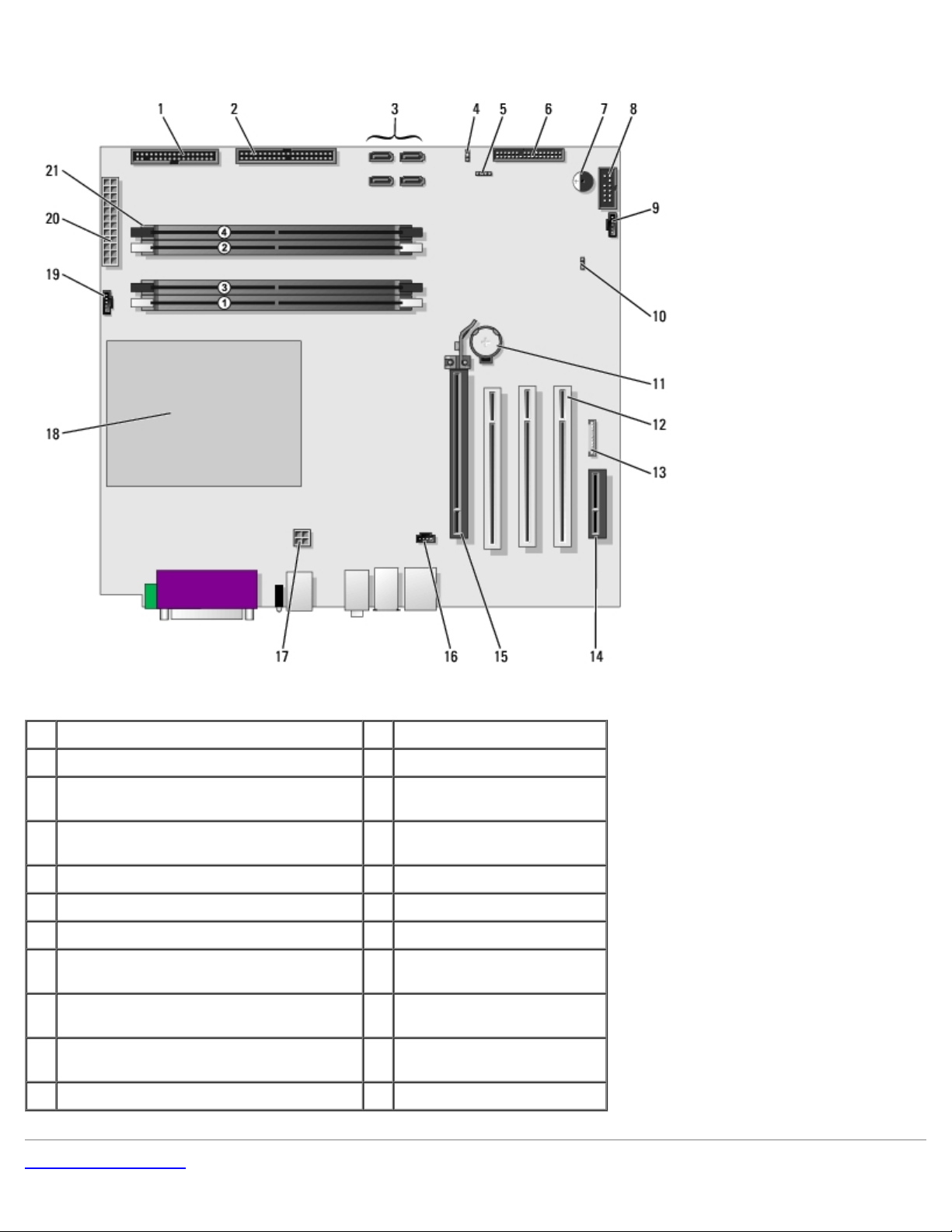
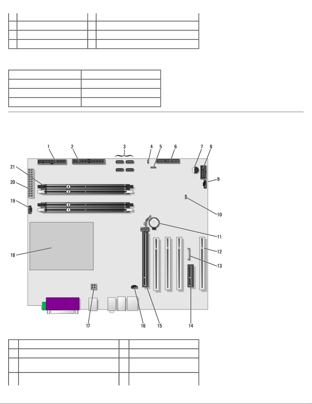
System Board Components
1 floppy drive (FLOPPY) 12 PCI card slots(1-3)
2 IDE drive (PRI IDE) 13 front panel audio (FP AUD)
3 SATA connectors (SATA-0, SATA-1,
SATA-2, SATA-3)
4 password jumper (PASS) 15 PCI-Express x16 up to
5 SCSI LED connector 16 CD audio input (CD IN)
6 front panel connector 17 processor power connector
7 speaker 18 processor socket
8 secondary serial port (SERIAL 2) 19 processor fan connector
9 card fan connector (PCI FAN) 20 main power connector
10 clear CMOS jumper (CLR CMOS) 21 memory modules
11 battery socket (BATTERY)
Back to Contents Page
14 PCI-Express x1 card slot
150w card slot
(CPU FAN)
(POWER)
connectors

Back to Contents Page
Your Desktop Computer
Dell Precision™ Workstation 370 User's Guide
Front View
Back View
Inside View
System Board Components
Front View
1 floppy-
drive
activity
light
2 hard-drive
activity
light
3 floppy-
drive eject
button
4 diagnostic
lights (4)
5 USB 2.0
connectors
(2)
6 IEEE 1394
connector
The floppy drive light is on when the computer reads data from or writes data
to the floppy drive. Wait until this light turns off before you remove the floppy
disk from the drive.
The hard drive light is on when the computer reads data from or writes data to
the hard drive. The light might also be on when a device such as your CD player
is operating.
Press to eject a floppy disk from the floppy drive.
Use the lights to help you troubleshoot a computer problem based on the
diagnostic code. For more information, see "Diagnostic Lights
Use the front USB connectors for devices that you connect occasionally, such as
flash memory keys or cameras, or for bootable USB devices (see system setup
for more information on booting to a USB device).
It is recommended that you use the back USB connectors for devices that
typically remain connected, such as printers and keyboards.
Attach high-speed serial multimedia devices, such as digital video cameras.
."
,
NOTE: To use the IEEE 1394 connector, you need an add-in-card that supports
this feature. To order a card contact Dell
.
7 headphone
connector
8 power
light
9 power
button
Use the headphone connector to attach headphones and most kinds of
speakers.
The power light illuminates and blinks or remains solid to indicate different
states:
No light — The computer is turned off.
Steady green — The computer is in a normal operating state.
Blinking green — The computer is in a power-saving state.
Blinking or solid amber — See "Power Problems."
To exit from a power-saving state, press the power button or use the keyboard
or the mouse if it is configured as a wake device in the Windows Device
Manager. For more information about sleep states and exiting from a powersaving state, see "Power Management
See "Diagnostic Lights
troubleshoot problems with your computer.
Press to turn on the computer.
NOTE: The power button can also be used to wake the system or to place it
into a power-saving state. See "Power Management
NOTICE: To avoid losing data, do not use the power button to turn off the
computer. Instead, perform an operating system shutdown.
" for a description of light codes that can help you
."
" for more information.
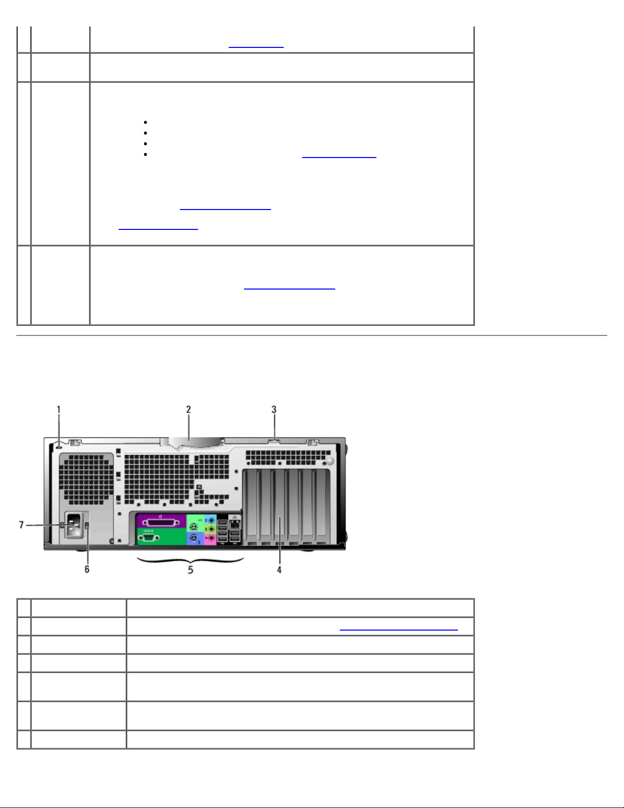
Back View
1 security cable slot Use a security cable with the slot to help secure your computer.
2 cover latch Releases the cover from the computer. See "Open the computer cover."
3 padlock ring Insert a padlock to lock the computer cover.
4 card slots Access connectors for any installed PCI or PCI Express cards.
5 back panel
connectors
6 voltage selection
switch
7 power connector Insert the power cable.
Plug serial, USB, and other devices into the appropriate connector.
See the safety instructions located in the Product Information Guide for
more information.
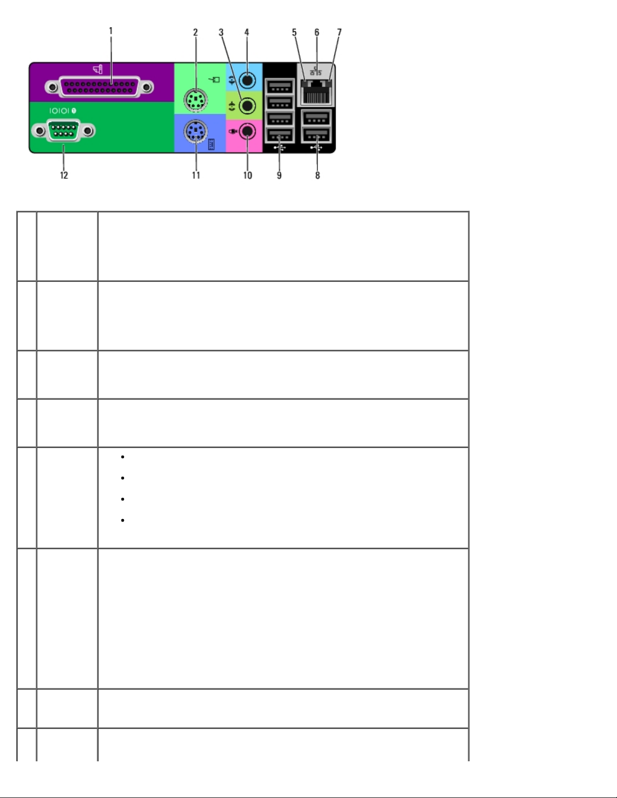
1 parallel
connector
Connect a parallel device, such as a printer, to the parallel connector. If you
have a USB printer, plug it into a USB connector.
NOTE: The integrated parallel connector is automatically disabled if the
computer detects an installed card containing a parallel connector configured
to the same address. For more information, see "System Setup Options."
2 mouse
connector
3 line-out
connector
4 line-in
connector
5 link
integrity
light
6 network
adapter
connector
Plug a standard mouse into the green mouse connector. Turn off the computer
and any attached devices before you connect a mouse to the computer. If you
have a USB mouse, plug it into a USB connector.
If your computer is running the Microsoft® Windows® XP operating system,
the necessary mouse drivers have been installed on your hard drive.
Use the green line-out connector to attach headphones and most speakers
with integrated amplifiers.
On computers with a sound card, use the connector on the card.
Use the blue line-in connector to attach a record/playback device such as a
cassette player, CD player, or VCR.
On computers with a sound card, use the connector on the card.
Green — A good connection exists between a 10-Mbps network and the
computer.
Orange — A good connection exists between a 100-Mbps network and
the computer.
Yellow — A good connection exists between a 1000-Mbps (or 1-Gbps)
network and the computer.
Off — The computer is not detecting a physical connection to the
network.
To attach your computer to a network or broadband device, connect one end
of a network cable to either a network jack or your network or broadband
device. Connect the other end of the network cable to the network adapter
connector on your computer. A click indicates that the network cable has been
securely attached.
7 network
activity
light
8 USB 2.0
connectors
NOTE: Do not plug a telephone cable into the network connector.
On computers with a network connector card, use the connector on the card.
It is recommended that you use Category 5 wiring and connectors for your
network. If you must use Category 3 wiring, force the network speed to 10
Mbps to ensure reliable operation.
Flashes a yellow light when the computer is transmitting or receiving network
data. A high volume of network traffic may make this light appear to be in a
steady "on" state.
Use the back USB connectors for devices that typically remain connected,
such as printers and keyboards.
(2)
It is recommended that you use the front USB connectors for devices that you
connect occasionally, such as flash memory keys or cameras, or for bootable
USB devices.
9 USB 2.0
connectors
(4)
10 microphone
connector
11 keyboard
connector
12 serial
connector
Use the back USB connectors for devices that typically remain connected,
such as printers and keyboards.
It is recommended that you use the front USB connectors for devices that you
connect occasionally, such as flash memory keys or cameras, or for bootable
USB devices.
Use the pink microphone connector to attach a personal computer microphone
for voice or musical input into a sound or telephony program.
On computers with a sound card, the microphone connector is on the card.
If you have a standard keyboard, plug it into the purple keyboard connector.
If you have a USB keyboard, plug it into a USB connector.
Connect a serial device, such as a handheld device, to the serial port. The
default designations are COM1 for serial connector 1 and COM2 for the
optional serial connector 2.
For more information, see "System Setup Options
."
Inside View
CAUTION: Before you begin any of the procedures in this section, follow the safety instructions located in
the Product Information Guide.
1 CD/DVD drive 5 processor airflow shroud and fan
2 floppy drive (optional) 6 security cable slot
3 hard drive 7 power supply
4 padlock ring
Cable Colors
Device Color
Hard drive Blue cable
Floppy drive Black pull tab
CD/DVD drive Orange pull tab
System Board Components
1 floppy drive (FLOPPY) 12 PCI card slots (1-3)
2 IDE drive (PRI IDE) 13 front panel audio (FP AUD)
3 SATA connectors (SATA-0, SATA-1,
SATA-2, SATA-3)
4 password jumper (PASS) 15 PCI-Express x16 up to
14 PCI-Express x1 card slot
150w card slot
5 SCSI LED connector 16 CD audio input (CD IN)
6 front panel connector 17 processor power connector
7 speaker 18 processor socket
8 secondary serial port (SERIAL 2) 19 processor fan connector
(CPU FAN)
9 card fan connector (PCI FAN) 20 main power connector
(POWER)
10 clear CMOS jumper (CLR CMOS) 21 memory modules
connectors
11 battery socket (BATTERY)
Back to Contents Page
Back to Contents Page
Advanced Features
Dell Precision™ Workstation 370 User's Guide
LegacySelect Technology Control
Manageability
Security
Password Protection
System Setup
Clearing Forgotten Passwords
Clearing CMOS Settings
Power Management
Hyper-Threading
IEEE 1394
U320 SCSI Controller
About RAID Configurations
LegacySelect Technology Control
LegacySelect technology control offers legacy-full, legacy-reduced, or legacy-free solutions based on common platforms,
hard-drive images, and help desk procedures. Control is provided to the administrator through system setup, Dell
OpenManage™ IT Assistant, or Dell™ custom factory integration.
LegacySelect allows administrators to electronically activate or deactivate connectors and media devices that include serial
and USB connectors, a parallel connector, a floppy drive, PCI slots, and a PS/2 mouse. Connectors and media devices that are
deactivated make resources available. You must restart the computer to effect the changes.
Manageability
Alert Standard Format
ASF is a DMTF management standard that specifies "pre-operating system" or "operating system-absent" alerting techniques.
The standard is designed to generate an alert on potential security and fault conditions when the operating system is in a
sleep state or the system is powered down. ASF is designed to supersede previous operating system-absent alerting
technologies.
Your computer supports the following ASF alerts:
Alert Description
BIOS: Corrupt BIOS/Corrupt BIOS Cleared
Boot: Failure to Boot to BIOS
Password: System Password Violation
CPU: CPU DOA Alert/CPU DOA Alert Cleared
Heartbeats: Entity Presence
Temperature: Generic Critical Temperature
Problem/Generic Critical Temperature Problem
Cleared
The BIOS has been corrupted or the BIOS corruption has been
resolved.
The BIOS did not complete loading upon initiation.
The system password is invalid (alert occurs after three failed
attempts).
The microprocessor is not functioning.
Periodic heartbeats have been transmitted to verify system
presence.
The computer temperature is out of limits or the computer
temperature problem has been resolved.

Voltage: Generic Critical Voltage Problem/Generic
Critical Voltage Problem Cleared
Power Supply: Critical Power Supply Problem/
Critical Power Supply Problem Cleared
Cooling Device: Generic Critical Fan
Failure/Generic Critical Fan Failure Cleared
Connectivity: Ethernet Connectivity Enabled/
Ethernet Connectivity Disabled
For more information about Dell's ASF implementation, see the ASF User's Guide and the ASF Administrator's Guide, which
are available on the Dell Support website at support.dell.com.
The voltage from integrated voltage regulators is out of limits
or the voltage problem has been resolved.
The computer power supply voltage is out of limits or the
computer power supply voltage problem has been resolved.
The fan speed (rpm) is out of limits or the fan speed (rpm)
problem has been resolved.
The ethernet connectivity is enabled or the ethernet
connectivity is disabled.
Dell OpenManage IT Assistant
IT Assistant configures, manages, and monitors computers and other devices on a corporate network. IT Assistant manages
assets, configurations, events (alerts), and security for computers equipped with industry-standard management software. It
supports instrumentation that conforms to SNMP, DMI, and CIM industry standards.
Dell OpenManage Client instrumentation, which is based on DMI and CIM, is available for your computer. For information on
IT Assistant, see the Dell OpenManage IT Assistant User's Guide available on the Dell Support website at support.dell.com.
Dell OpenManage Client Instrumentation
Dell OpenManage Client Instrumentation is software that enables remote management programs such as IT Assistant to do
the following:
Access information about your computer, such as how many processors it has and what operating system it is running
Monitor the status of your computer, such as listening for thermal alerts from temperature probes or hard-drive failure
alerts from storage devices
Change the state of your computer, such as updating its BIOS or shutting it down remotely
A managed system is one that has Dell OpenManage Client Instrumentation set up on a network that uses IT Assistant. For
information about Dell OpenManage Client Instrumentation, see the Dell OpenManage Client Instrumentation User's Guide
available on the Dell Support website at support.dell.com.
Security
Chassis Intrusion Detection
NOTE: When the admin password is enabled, you must know the admin password before you can reset the Chassis
Intrusion setting.
This feature detects that the chassis was opened and alerts the user. To change the Chassis Intrusion setting:
1. Enter system setup.
2. Press the down-arrow keys to move to the System Security option.
3. Press <Enter> to access the menu.

4. Use the left- and right-arrow key to select an option setting.
5. Exit system setup.
Option Settings
Enabled — If the computer cover is opened, the setting changes to Detected, and the following alert message
displays during the boot routine at the next computer start-up:
Alert! Cover was previously removed.
To reset the Detected setting, enter system setup. In the Chassis Intrusion option, press the left- or right-arrow key
to select Reset, and then choose Enabled, Enabled-Silent, or Disabled.
Enabled-Silent (default) — If the computer cover is opened, the setting changes to Detected. No alert message
appears during the boot sequence at the next computer start-up.
Antitheft devices usually include a segment of metal-stranded cable with an attached locking device and key. The
documentation that comes with the device contains instructions for installing it.
Padlock Ring and Security Cable Slot
Use one of the following methods to secure your computer:
Use a padlock alone or a padlock and looped security cable with the padlock ring.
A padlock alone prevents the computer from being opened.
A security cable looped around a stationary object is used in conjunction with a padlock to prevent unauthorized
movement of the computer.
Attach a commercially available antitheft device to the security cable slot on the back of the computer.
NOTE: Before you purchase an antitheft device, make sure that it works with the security cable slot on your computer.
Antitheft devices usually include a segment of metal-stranded cable with an attached locking device and key. The
documentation that comes with the device contains instructions for installing it.
Password Protection
NOTICE: Although passwords provide security for the data on your computer, they are not foolproof. If your data
requires more security, it is your responsibility to obtain and use additional forms of protection, such as data
encryption programs.
System Password
NOTICE: If you leave your computer running and unattended without having a system password assigned, or if you
leave your computer unlocked so that someone can disable the password by changing a jumper setting, anyone can

access the data stored on your hard drive.
Option Settings
You cannot change or enter a new system password if either of the following two options is displayed:
Disabled — The system password is disabled by a jumper setting on the system board.
You can only assign a system password when the following option is displayed:
Set — A system password is assigned.
Not Enabled — No system password is assigned and the password jumper on the system board is in the enabled
position (the default).
Assigning a System Password
To escape from the field without assigning a system password, press <Tab> or the <Shift><Tab> key combination to move
to another field, or press <Esc> at any time before you complete step 5.
1. Enter system setup
2. Highlight System Password, and then press <Enter>.
The option heading changes to Enter Password, followed by an empty 32-character field in square brackets.
3. Type your new system password.
You can use up to 32 characters. To erase a character when entering your password, press <Backspace> or the leftarrow key. The password is not case sensitive.
Certain key combinations are not valid. If you enter one of these combinations, the cursor will not move.
As you press each character key (or the spacebar for a blank space), a placeholder appears in the field.
4. Press <Enter>.
If the new system password is less than 32 characters, the whole field fills with placeholders. Then the option heading
changes to Confirm Password, followed by another empty 32-character field in square brackets.
5. To confirm your password, type it a second time and press <Enter>.
and verify that Password Status is set to Unlocked.
The password setting changes to Set.
6. Exit system setup.
Password protection takes effect when you restart the computer.
Typing Your System Password

When you start or restart your computer, one of the following prompts appears on the screen.
If Password Status is set to Unlocked:
Type in the password and
- press <ENTER> to leave password security enabled.
- press <CTRL><ENTER> to disable password security.
Enter password:
If Password Status is set to Locked:
Type the system password and press <Enter>.
Enter password:
If you have assigned a setup password, the computer accepts your setup password as an alternate system password.
If you type a wrong or incomplete system password, the following message appears on the screen:
** Incorrect password. **
If you again type an incorrect or incomplete system password, the same message appears on the screen. The third and
subsequent times you type an incorrect or incomplete system password, the computer displays the following message:
** Incorrect password. **
Number of unsuccessful password attempts: 3
System halted! Must power down.
Even after your computer is turned off and on, the previous message is displayed each time you type an incorrect or
incomplete system password.
NOTE: You can use Password Status in conjunction with System Password and Admin Password to further
protect your computer from unauthorized changes.
Changing or Deleting an Existing System Password
To change a system password, follow the procedure in "Assigning a System Password."
To delete a system password:
1. Enter system setup.
2. Highlight System Password and press <Enter>
3. When prompted, type the system password.
4. Press <Enter> twice to clear the existing setup password. The setting changes to Not Set.
5. To assign a new password, follow the procedure in "Assigning a System Password
."
Admin Password
Option Settings

Set — Does not allow assignment of setup passwords; users must enter a setup password to make changes to system
setup
Not Set — Allows assignment of setup passwords; password feature is enabled but no password is assigned
Disabled —The admin password is disabled by a jumper setting on the system board
Assigning a Setup Password
The setup password can be the same as the system password.
NOTE: If the two passwords are different, the setup password can be used as an alternate system password. However,
the system password cannot be used in place of the setup password.
1. Enter system setup
2. Highlight Admin Password and press the left- or right-arrow key.
The computer prompts you to type and verify the password. If a character is not permitted, the computer emits a
beep.
3. Type and then verify the password.
After you verify the password, the Admin Password setting changes to Enabled. The next time you enter system
setup, the computer prompts you for the setup password.
4. Exit system setup.
A change to Admin Password becomes effective immediately (no need to restart the computer).
and verify that Admin Password is set to Not Enabled.
Operating Your Computer With a Admin Password Enabled
When you enter system setup, the Admin Password option is highlighted, prompting you to type the password.
If you do not type the correct password, the computer lets you view, but not modify, system setup options.
NOTE: You can use Password Status in conjunction with Admin Password to protect the system password from
unauthorized changes.
Deleting or Changing an Existing Admin Password
To change an existing admin password, you must know the admin password.
1. Enter system setup
2. Type the admin password at the prompt.
3. Press <Enter> twice to clear the existing admin password. The setting changes to Not Set.
To assign a new setup password, you can also perform the procedure in "Assigning a System Password
.
."

Disabling a Forgotten Password and Setting a New Password
To reset system and/or admin passwords, see "Clearing Forgotten Passwords."
System Setup
Overview
Use system setup as follows:
To change the system configuration information after you add, change, or remove any hardware in your computer
To set or change a user-selectable option such as the user password
To read the current amount of memory or set the type of hard drive installed
Before you use system setup, it is recommended that you write down the system setup screen information for future
reference.
Entering System Setup
1. Turn on (or restart) your computer.
2. When the blue DELL™ logo appears, press <F2> immediately.
If you wait too long and the operating system logo appears, continue to wait until you see the Microsoft® Windows®
desktop. Then shut down your computer
System Setup Screens
The system setup screen displays current or changeable configuration information for your computer. Information on the
screen is divided into three areas: the options list, active options field, and key functions.
Options List — This field appears on the left side of the system setup
window. The field is a scrollable list containing features that define the
configuration of your computer, including installed hardware, power
conservation, and security features.
Scroll up and down the list by using the up and down arrow keys. As an
option is highlighted, the Option Field displays more information about that
option and the option's current and available settings.
and try again.
Option Field — This field contains information
about each option. In this field you can view
your current settings and make changes to
your settings.
Use the right and left arrow keys to highlight
an option. Press <Enter> to make that
selection active.
 Loading...