

Page 1

Dell EMC Networking OS10 Enterprise Edition
Deployment Guide with Cisco ACI
Abstract
This document provides steps for the configuration and deployment of
Dell EMC Networking switches running Dell EMC OS10 Enterprise
Edition, into a Cisco ACI environment.
December 2018
Dell EMC Configuration and Deployment Guide
Page 2

Date
Description
December 2018
Initial release
Revisions
The information in this publication is provided “as is.” Dell Inc. makes no representations or warranties of any kind with respect to the information in this
publication, and specifically disclaims implied warranties of merchantability or fitness for a particular purpose.
Use, copying, and distribution of any software described in this publication requires an applicabl e software lic ense.
© 2018 Dell Inc. or its subsidiaries. All Rights Reserved. Dell, EMC, Dell EMC and other trademarks are trademarks of Dell Inc. or its subsidiaries. Other
trademarks may be trademarks of their respective owners.
Dell believes that the information in this document is accurate as of its publication date. The information is subject to change without notice.
2 Dell EMC Networking OS10 Enterprise Edition Deployment Guide with Cisco ACI
Page 3

Table of contents
Revisions............................................................................................................................................................................. 2
1 Introduction ................................................................................................................................................................... 5
1.1 Typographical conventions ................................................................................................................................. 5
1.2 Attachments ........................................................................................................................................................ 6
2 Hardware overview ....................................................................................................................................................... 7
2.1 Dell EMC Networking S5248F-ON ..................................................................................................................... 7
2.2 Dell EMC Networking S4148F-ON ..................................................................................................................... 7
2.3 Dell EMC Networking S3048-ON ....................................................................................................................... 7
2.4 Cisco Nexus C93180YC-EX ............................................................................................................................... 8
2.5 Cisco Nexus C9336-PQ ..................................................................................................................................... 8
2.6 Supported Dell EMC switches ............................................................................................................................ 8
3 Cisco Application Centric Infrastructure (ACI) .............................................................................................................. 9
4 Dell EMC ToR switches with Cisco ACI environment overview ................................................................................. 10
4.1 Validated environment ...................................................................................................................................... 11
5 OOB Management network ........................................................................................................................................ 13
6 Cisco APIC configuration ........................................................................................................................................... 15
7 Configure S5248F-ON switches ................................................................................................................................. 17
7.1 OOB management configuration ...................................................................................................................... 17
7.2 VLT configuration.............................................................................................................................................. 17
7.3 Configure the VLANs ........................................................................................................................................ 18
7.4 Server-facing configuration ............................................................................................................................... 19
7.5 Switch pair uplink configuration ........................................................................................................................ 20
8 vCenter configuration overview .................................................................................................................................. 21
9 Verify configuration ..................................................................................................................................................... 23
9.1 Validation using OS10EE CLI ........................................................................................................................... 23
9.1.1 show vlt [domain-id] command ........................................................................................................................ 23
9.1.2 show vlt [domain-id] vlt-port-detail command ................................................................................................... 24
9.1.3 show interface port channel summary command ............................................................................................. 24
9.1.4 show lldp neighbors command ......................................................................................................................... 24
9.1.5 show spanning-tree brief command ................................................................................................................. 25
9.1.6 show uplink state group command ................................................................................................................... 25
9.2 Cisco ACI validation ......................................................................................................................................... 26
9.2.1 Verify vPC configuration ................................................................................................................................... 26
9.2.2 Verify physical interface conf igurati on .............................................................................................................. 28
9.2.3 Verify ACI is learning endpoints ....................................................................................................................... 29
3 Dell EMC Networking OS10 Enterprise Edition Deployment Guide with Cisco ACI
Page 4

9.3 Verify connectivity between VMs ...................................................................................................................... 30
A Additional informat ion ................................................................................................................................................. 31
A.1 Reset OS10EE switches to factory defaults ..................................................................................................... 31
A.2 Spanning Tree Protocol recommendations ...................................................................................................... 31
B Validated components ................................................................................................................................................ 32
B.1 Dell EMC Networking switches ......................................................................................................................... 32
B.2 Cisco ACI components ..................................................................................................................................... 32
C Technical resources ................................................................................................................................................... 33
D Support and feedback ................................................................................................................................................ 34
4 Dell EMC Networking OS10 Enterprise Edition Deployment Guide with Cisco ACI
Page 5
This guide is
This guide is not/does not
A reference for basic configuration of a top-ofrack (ToR) pair of switches using OS10EE
A guide for all features of OS10EE-based
switches
An example of one way to add ToR switches to
an existing Cisco ACI environment
A guide for adding Cisco ACI to a complete leafspine deployment
1 Introduction
Dell EMC Networking is committed to providing customers with modern data center networking technology to
be the foundation for digital transformation. Customers can choose from a wide range of industry-standard
network applications, operating systems, and hardware platforms to realize cost savings and improvement in
service agility.
This document provides an example for the deployment of a pair of top-of-rack (ToR) Dell EMC Networking
switches into an existing Cisco Application Centric Infrastructure (ACI) environment. The example details how
Layer 2 domains can be extended into and out of an ACI fabric with Dell EMC Networking switches in a way
that provides high throughput and failure tolerance. The example shows how devices that are connected to
Dell EMC Networking switches can be integrated with the ACI fabric to communicate with and access ACI
resources.
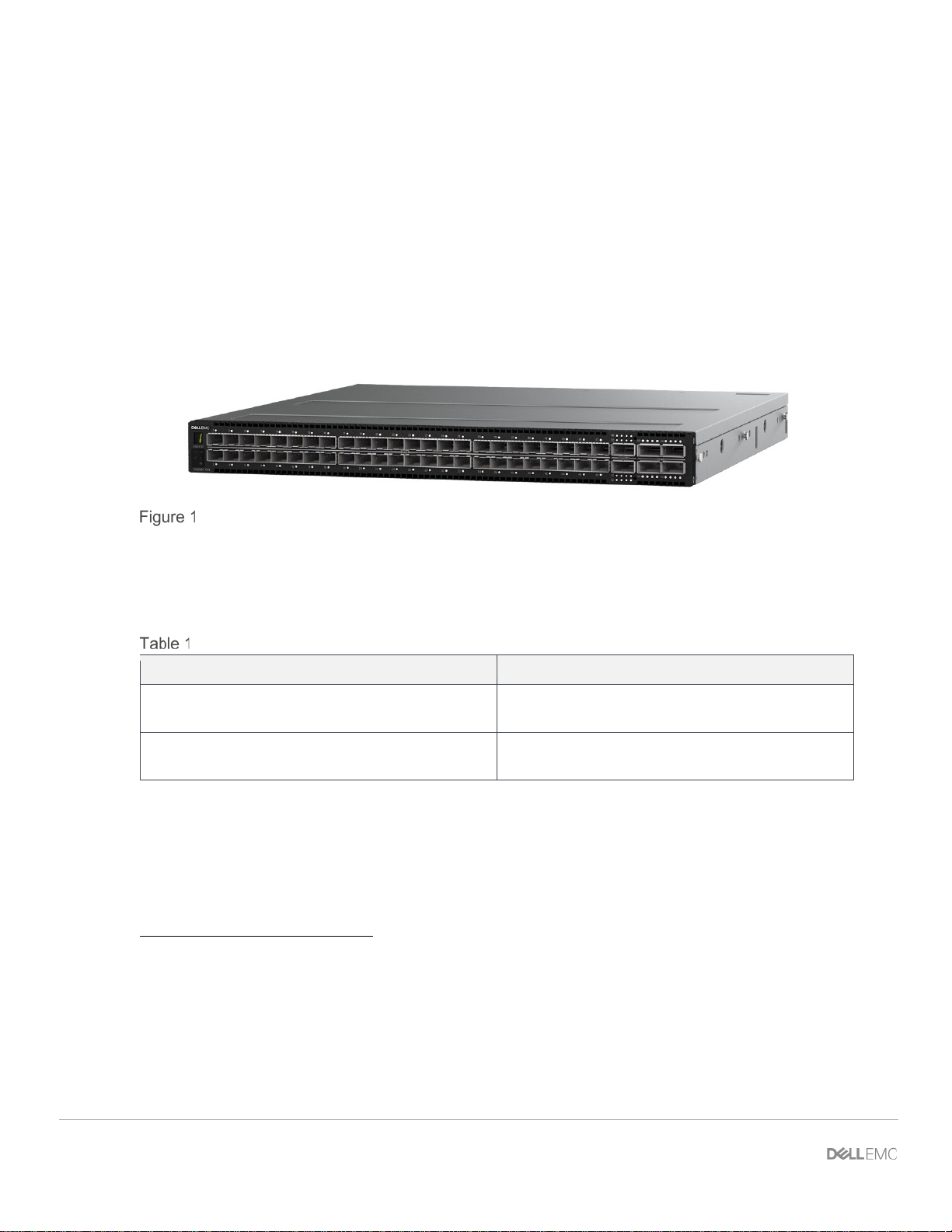
Dell EMC Networking S52 4 8F -ON switch
The deployment example includes instructions to configure a pair of Dell EMC S5248F-ON switches. The
example demonstrates connectivity to a pair of Cisco Nexus C93180YC-EX switches in ACI mode.
Table 1 outlines what this document is and is not.
Dell EMC Networking OS10EE Deployment Guide with Cisco ACI
1.1 Typographical conventions
The CLI and GUI examples in this document use the following conventions:
Monospace Text CLI examples
Underlined Monospace Text CLI examples that wrap the page
Italic Monospace Text Variables in CLI examples
Bold Monospace Text Commands entered at the CLI prompt, or to highlight information in CLI
Bold text UI elements and information that is entered in the GUI
5 Dell EMC Networking OS10 Enterprise Edition Deployment Guide with Cisco ACI
output
Page 6

1.2 Attachments
This document in .pdf format includes one or more file attachments. To access attachments in Adobe Acrobat
Reader, click the icon in the left pane halfway down the page, and then click the icon.
6 Dell EMC Networking OS10 Enterprise Edition Deployment Guide with Cisco ACI
Page 7
2 Hardware overview
This section briefly describes the hardware that is used to validate the deployment examples in this
document. Appendix B
Note: While the steps in this document were validated using the specified Dell EMC Networking switches and
operating systems, they may be used for other Dell EMC Networking switch models using the same
networking operating system version or later assuming the switch has the available port numbers, speeds,
and types. The two switch models in this section are detailed based on being the most commonly deployed
ToR switches in the current portfolio.
2.1 Dell EMC Networking S5248F-ON
The Dell EMC Net work ing S52 48F-ON is a 1-Rack Unit (RU) switch with forty-eight 25GbE SFP28 ports, two
2x100GbE QSFP28-DD ports, and four 100GbE QSFP28 ports. The high-performance S5248F-ON switch is
an optimal choice for ToR environments requiring connectivity for 10GbE and 25GbE compute and storage.
contains a complete listing of hardware and software that is validated for this guide.
Dell EMC Networking S52 4 8F -ON switch
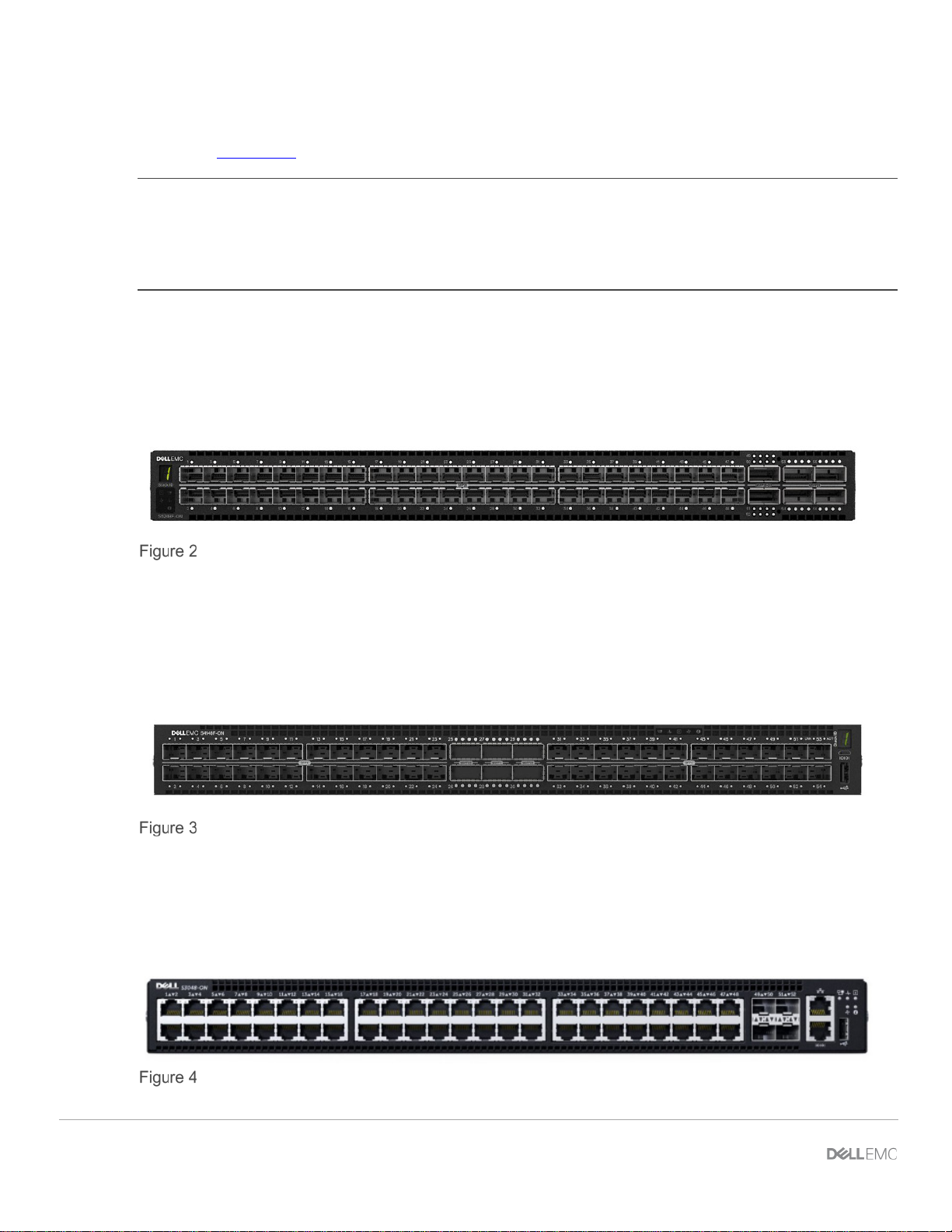
2.2 Dell EMC Networking S4148F-ON
The Dell EMC Networking S4148F-ON is a 1-RU switch with forty-eight 10GbE SFP+ ports, two 40GbE
QSFP+ ports, and four 100GbE QSFP28 ports. The high-performance S4148F-ON switch is an optimal
choice for ToR environments requiring connectivity for 10GbE compute and storage.
Dell EMC Networking S4148F-ON switch
2.3 Dell EMC Networking S3048-ON
The Dell EMC Networking S3048-ON is a 1-RU switch with forty-eight 1GbE BASE-T ports and four 10GbE
SFP+ ports. In this document, one S3048-ON supports out-of-band (OOB) management traffic for all
examples.
Dell EMC Networking S3048-ON
7 Dell EMC Networking OS10 Enterprise Edition Deployment Guide with Cisco ACI
Page 8

Dell EMC Networking Switch
OS10EE,
S5248F-ON
Supported, validated version 10.4.2
S4148F-ON
Supported
S5048F-ON
Supported
S5148F-ON
Supported
S5296F-ON
Supported
S5232F-ON
Supported
S6010-ON
Supported
S6100-ON
Supported
S4048-ON
Supported
S4048T-ON
Supported
S4112F-ON
Supported, validated version 10.4.2
S4112T-ON
Supported
S4128F-ON
Supported
S4128T-ON
Supported
S4148T-ON
Supported
S4148FE
Supported
S4148U
Supported, validated version 10.4.2
S4248FB-ON
Supported
S4248FBL-ON
Supported
2.4 Cisco Nexus C93180YC-EX
The Cisco Nexus C93180YC-EX switch is a 1-RU switch with forty-eight 1/10/25GbE ports and six
40/100GbE ports. A pair of Cisco Nexus C93180YC-EX switches are used as Cisco ACI leaf switches in the
demonstrated environment in this guide.
2.5 Cisco Nexus C9336-PQ
The Cisco Nexus C9336-PQ switch is a 2-RU switch with thirty-six 40GbE QSFP+ ports. One Cisco Nexus
C9336-PQ switch is used as a Cisco ACI spine switch in the demonstrated environment in this guide.
2.6 Supported Dell EMC switches
The switch models hig hl ig h ted in blue in Table 2, have been validated in the lab environment that is detailed
in section 0. All Dell EMC Networking switches that run the OS10EE operating system can be used in a
similar deployment with Cisco ACI. Tested and supported features in the Cisco ACI environment include VLT
and Layer 2 operation.
Supported Dell EMC Networking switches
version 10.4.0R3 and later
Note: Dell EMC provides this supported list as is, without express or implied warranties of any kind. This list
is for informational purposes only and may contain typographical and technical inaccuracies. Dell EMC is not
liable for any damages that arise out of or in connection with the use of the information provided in this list.
Table 2 includes only switches that are commonly deployed as ToR switches. All switch models that run
OS10EE deployed in a VLT topology in Layer 2 operation can be considered. Some switches contain
features, such as Fibre Channel, that have not been validated to work with Cisco API and is out of the scope
of this document.
8 Dell EMC Networking OS10 Enterprise Edition Deployment Guide with Cisco ACI
Page 9

3 Cisco Application Centric Infrastructure (ACI)
Cisco ACI is an application focused, software-defined net working solution utilizing both software and
traditional switching hardware. The solution is an overlay on Cisco’s high-performance switches, operating in
an ACI mode managed b y a controll er . The Cisco Application Policy Infrastructure Controller (APIC) is a
central management appliance that handles policy, visibility, security, and overall network control for the ACI
environment.
Cisco ACI provides the following features within the ACI domain:
• Multi-tenant security
• Microsegmentation
• Application specific policy management
• Network availability and QoS
• Network automation
9 Dell EMC Networking OS10 Enterprise Edition Deployment Guide with Cisco ACI
Page 10
4 Dell EMC ToR switches with Cisco ACI environment
overview
The example that is shown in this paper covers deploying S5248F-ON switches connected to a Cisco ACI
environment. By integrat in g the ToR switch pair into an ACI environment, compute resources within the rack
can use ACI gateways and access ACI resources.
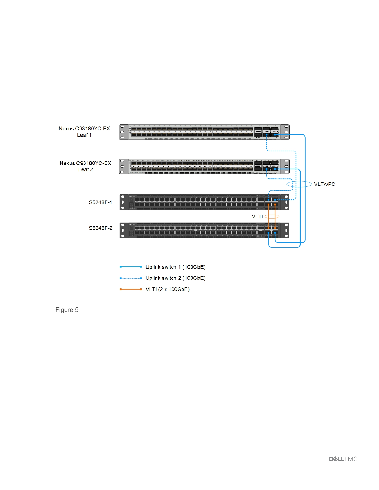
The validated Cisco ACI environment includes a pair of Nexus C93180YC-EX switches as leaf switches as
shown in Figure 5. The C93180YC-EX leaf switch pair are connected to a single Nexus C9336-PQ spine
using 40GbE uplinks (not shown).
Dell EMC Networking switches connected to Cisco ACI leaf switches
Connections from S5248F-ON switches to the C93180YC-EX leaf pair are 100 GbE. These connections are
shown in blue in Figur e 5.
Note: The wiring diagram in Figure 5 is drawn to show the types of connections in a carefully arranged
fashion for clarity. The port numbers and connection locations may differ in the actual deployment.
No physical peer link is used between the Cisco ACI leaf switches. See the Cisco ACI documentation for
more information.
10 Dell EMC Networking OS10 Enterprise Edition Deployment Guide with Cisco ACI
Page 11
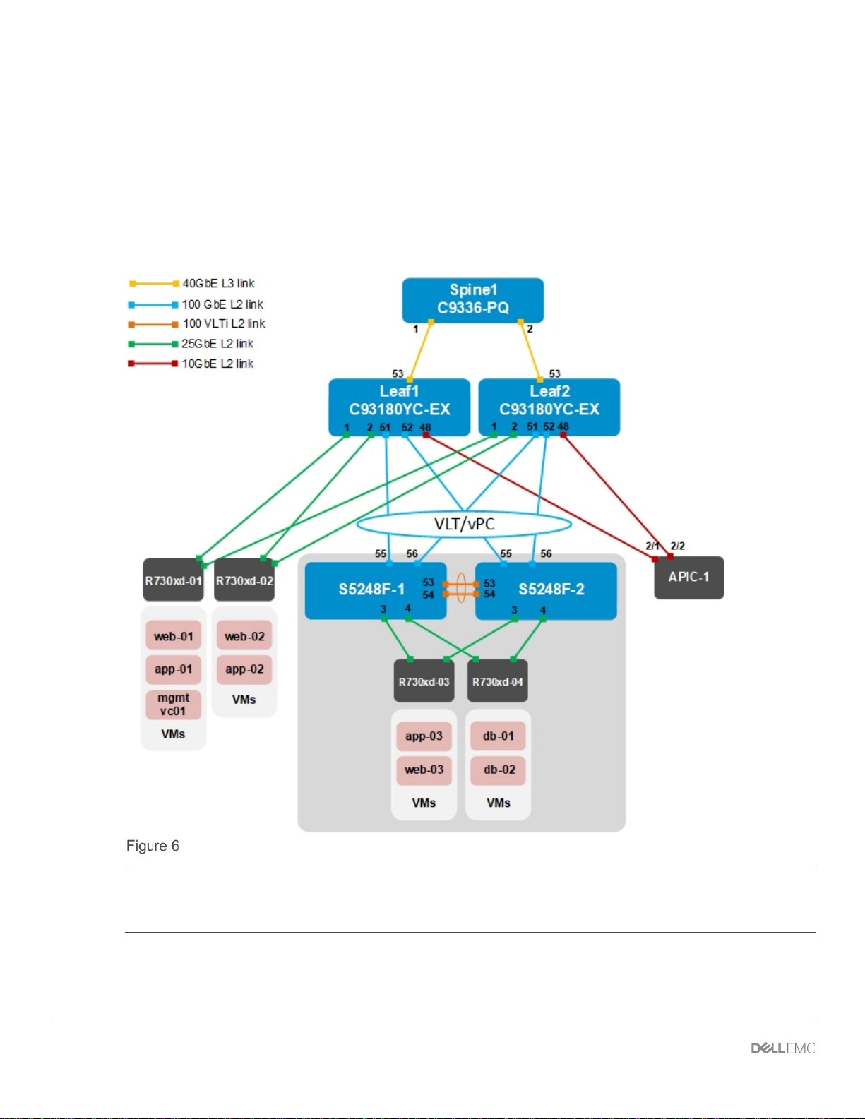
4.1 Validated environment
In this example, two S5248F-ON switches are joined to an existing Cisco ACI environment. The rack contains
two S5248F-ON and four PowerEdge R730xd servers.
The connections between the ACI environment and the S5248F-ON switches consist of double-sided multichassis link aggregation group (MLAG). The double-sided MLAG connection consists of a vPC on the Cisco
ACI side and a VLT port channel on the S5248F-ON side.
All of the devices in the validated environment that are covered in this chapter, are connected as shown in
Figure 6.
Validated Dell EMC ToR and ACI environment
Note: No physical peer link is used between the Cisco ACI leaf switches. See the Cisco ACI documentation
for more information. Cisco recommends a minimum of three Application Policy Infrastructure Controllers
(APICs) in a production environment. For this validation effort, a single APIC, named APIC-1, is used.
All Dell EMC PowerEdge R730xd rack servers in this example are running VMware ESXi 6.7.0. VMs named
“web,” “app,” and “db” on the ESXi hosts are running Ubuntu Linux guest operating systems.
11 Dell EMC Networking OS10 Enterprise Edition Deployment Guide with Cisco ACI
Page 12

VLAN ID
VLAN name
Description
Network address
Gateway address
1612
vMotion
VM migration
172.16.12.0/24
172.16.12.254
1613
vSAN
Storage
172.16.13.0/24
172.16.13.254
1614
web
VM data network
172.16.14.0/24
172.16.14.254
1615
app
VM data network
172.16.15.0/24
172.16.15.254
1616
db
VM data network
172.16.16.0/24
172.16.16.254
VM name
VLAN name
IP address
mgmtvc01
ESXi_Mgmt
100.67.163.171
web01-web03
web
172.16.14.1-3
app01-app03
app
172.16.15.1-3
db01-db02
db
172.16.16.1-2
The existing Cisco ACI environment has two PowerEdge R730xd rack servers that are directly connected to
the ACI leaf switches. These rack servers are in a VMware vSphere cluster, with a vCenter VM named
mgmtvc01 on R730xd-01 as shown in Fi gure 6.
Integrating the S5248F-ON switches into the Cisco ACI environment enables the four PowerEdge R730xd
servers in the rack to join the existing VMware vSphere cluster. This enables all hosts and VMs to
communicate using the relevant networks.
The in-band test environment uses the five networks that are shown in Table 3.
In-band networks used
Note: While the VMware vSph er e vMot io n and vSAN networks are configured in this example, their use is out
of scope for this guide.
VMs in the validated environment use the IP addresses shown in Table 4.
VM IP addresses
12 Dell EMC Networking OS10 Enterprise Edition Deployment Guide with Cisco ACI
Page 13

5 OOB Management network
Network topological designs are not complete without a layer for management traffic. The OOB management
network is a separate network for management traffic only. Administrators use the OOB management network
to configure, manage, and monitor devices such as servers and switches. Payload traffic that is initiated by
network end users does not traverse the OOB management network. Switches used for management are
1GbE. Figure 7 demonstrates how the Dell EMC Networking S3048-ON switch may be used for this purpose.
Management network example for a single rack
Figure 7 shows an OOB management network for a single rack. More racks can be added to the same
management network. A Dell EMC Networking S3048-ON may be used to manage up to 48 devices on the
network, typically enough for a single rack of equipment. The switch may then be connected to other adjacent
management switches, or upstream to a management core.
13 Dell EMC Networking OS10 Enterprise Edition Deployment Guide with Cisco ACI
Page 14

Figure 8 shows how the OOB management network was configured for the demonstrated environment,
alongside the connections used for in-band production traffic. There are two OOB management connections
for each server: one that is used for ESXi management and one that is used for providing connectivity to the
server iDRAC. The production in-band uplinks to the ACI environment are not shown.
OOB management network cabling alongside in-band produc ti on net wor k
14 Dell EMC Networking OS10 Enterprise Edition Deployment Guide with Cisco ACI
Page 15

VLAN
ID
Gateway IP
address/mask
1612
vMotion
172.16.12.254/24
vMotionBD1
vMotionEPG1
1613
vSAN
172.16.13.254/24
vSANBD1
vSANEPG1
1614
web
172.16.14.254/24
webBD1
webEPG1
1615
app
172.16.15.254/24
appBD1
appEPG1
1616
db
172.16.16.254/24
dbBD1
dbEPG1
6 Cisco APIC configuration
The Cisco APIC configuration includes the ports that are connected to the R730xd rack servers and the vPC
that connects to the S5248F-ON VLT port channel. Included are the configuration of the ACI fabric interfaces,
switches, and application-level elements such as ACI endpoint groups (EPGs) and bridge domains.
The networks that are used in the validated environment are shown in Table 5, along with the corresponding
bridge domain, and application EPG names used in APIC configuration.
Validated environment network information
VLAN name
In this deployment, EPGs are extended outside of the ACI fabric by mapping EPGs to external VLANs. This is
so when a frame tagged with VLAN 1611, for example, enters the ACI fabric, ACI knows that it belongs to the
ESXi Management EPG and treats it accordingly.
Bridge domain name Application EPG name
15 Dell EMC Networking OS10 Enterprise Edition Deployment Guide with Cisco ACI
Bridge domains are associated with EPGs, which are mapped to external VLANs.
Page 16

APIC configuration steps that are used in the validated environment are provided in the attachment titled
OS10EE Deployment Guide - Cisco APIC configuration steps. See the Cisco ACI documentation for
detailed APIC configuration instructions.
Note: In this environment, the 100 GbE ports on the ACI leaf switches are used as downlinks to the S5248FON switches. By default, the 100 GbE switch ports are designated for fabric connections, such as
connections to ACI spine switches. To use these 100 GbE switch ports for connecting to devices outside of
the ACI fabric, they must be configured as downlinks. Refer to Cisco documentation for more information.
16 Dell EMC Networking OS10 Enterprise Edition Deployment Guide with Cisco ACI
Page 17

S5248F-1
S5248F-2
configure terminal
100.67.166.254
configure terminal
100.67.166.254
7 Configure S5248F-ON switches
The following section outlines the configuration commands that are issued to the Dell EMC Networking
S5248F-ON ToR switches.
7.1 OOB management configuration
The OOB port for the Dell EMC Networking S5248F-ON is mgmt 1/1/1. The following commands show
how to configure this OOB port when using OS10EE. The switches start at their factory default settings as
described in Appendix A.1
Note: The S5248F-ON CLI is accessible through the console port or by using SSH. The default username
and password are both admin.
OOB management configuration
.
hostname S5248F-1
interface mgmt 1/1/1
no ip address dhcp
no shutdown
ip address 100.67.166.33/24
management route 0.0.0.0/0
Note: The configuration for the S3048-ON management switch is not shown. The configuration and
deployment of the overall management network is not within the scope of this document.
7.2 VLT configuration
In this example, configure VLT between the two Dell EMC S5248F-ON switches. VLT synchronizes Layer 2
and ARP table information between the switches and enables a single port channel to be connected to the
switch pair as if they are a single switch.
1. Set up VLT on S5248F-1 using the commands in the first column of Table 7 (recommended port
values are shown).
hostname S5248F-2
interface mgmt 1/1/1
no ip address dhcp
no shutdown
ip address 100.67.166.32/24
management route 0.0.0.0/0
2. Configure S5248F-2 using the commands in column 2 provided in Table 7.
17 Dell EMC Networking OS10 Enterprise Edition Deployment Guide with Cisco ACI
Page 18

S5248F-1
S5248F-2
interface range ethernet 1/1/53-1/1/54
1/1/54
interface range ethernet 1/1/53-1/1/54
1/1/54
VLAN ID
VLAN name
Description
Tagged/Untagged
1612
vMotion
VM migration
Tagged
1613
vSAN
Storage
Tagged
1614
web
VM data network
Tagged
1615
app
VM data network
Tagged
1616
db
VM data network
Tagged
VLT configuration
description VLTi
no shutdown
no switchport
vlt-domain 127
backup destination 100.67.166.32
discovery-interface ethernet 1/1/53-
7.3 Configure the VLANs
The VLAN settings that are used during deployment for this environment are shown in Table 8.
VLAN settings
description VLTi
no shutdown
no switchport
vlt-domain 127
backup destination 100.67.166.33
discovery-interface ethernet 1/1/53-
18 Dell EMC Networking OS10 Enterprise Edition Deployment Guide with Cisco ACI
Page 19

S5248F-1
S5248F-2
interface vlan 1612
no shutdown
interface vlan 1612
no shutdown
S5248F-1
S5248F-2
interface ethernet 1/1/3
spanning-tree port type edge
interface ethernet 1/1/3
spanning-tree port type edge
VLAN configuration
description vMotion
no shutdown
interface vlan 1613
description vSAN
no shutdown
interface vlan 1614
description web
no shutdown
interface vlan 1615
description app
no shutdown
interface vlan 1616
description db
7.4 Server-facing configuration
Configure the server-facing interfaces with the following steps.
Server-facing configuration
description vMotion
no shutdown
interface vlan 1613
description vSAN
no shutdown
interface vlan 1614
description web
no shutdown
interface vlan 1615
description app
no shutdown
interface vlan 1616
description db
description "R730xd-03 p1"
no shutdown
switchport mode trunk
switchport access vlan 1
switchport trunk allowed vlan 1612-1616
spanning-tree port type edge
interface ethernet 1/1/4
description "R730xd-04 p1"
no shutdown
switchport mode trunk
switchport access vlan 1
switchport trunk allowed vlan 1612-1616
description "R730xd-03 p2"
no shutdown
switchport mode trunk
switchport access vlan 1
switchport trunk allowed vlan 1612-1616
spanning-tree port type edge
interface ethernet 1/1/4
description "R730xd-04 p2"
no shutdown
switchport mode trunk
switchport access vlan 1
switchport trunk allowed vlan 1612-1616
19 Dell EMC Networking OS10 Enterprise Edition Deployment Guide with Cisco ACI
Page 20

S5248F-1
S5248F-2
interface port-channel 100
interface port-channel 100
7.5 Switch pair uplink configuration
Configure the VLT port channel and interfaces connecting to the ACI leaf switches. Configure and enable
uplink failure detection (UFD).
Uplink configuration
description "ACI connection"
no shutdown
switchport mode trunk
switchport access vlan 1
switchport trunk allowed vlan 1612-1616
vlt-port-channel 100
interface ethernet 1/1/55
description "ACI connection leaf 1 eth
1/1"
no shutdown
channel-group 100 mode active
no switchport
interface ethernet 1/1/56
description "ACI connection leaf 2 eth
1/1"
no shutdown
channel-group 100 mode active
no switchport
uplink-state-group 1
enable
downstream ethernet1/1/3-1/1/4
upstream port-channel 100
description "ACI connection"
no shutdown
switchport mode trunk
switchport access vlan 1
switchport trunk allowed vlan 1612-1616
vlt-port-channel 100
interface ethernet 1/1/55
description "ACI connection leaf 1 eth
1/2"
no shutdown
channel-group 100 mode active
no switchport
interface ethernet 1/1/56
description "ACI connection leaf 2 eth
1/2"
no shutdown
channel-group 100 mode active
no switchport
uplink-state-group 1
enable
downstream ethernet1/1/3-1/1/4
upstream port-channel 100
Note: UFD is a feature that disables downlink interfaces due to uplink interface failures. Configuration of UFD
is a best practice to prevent downstream resources from sending traffic to a switch with failed uplinks.
20 Dell EMC Networking OS10 Enterprise Edition Deployment Guide with Cisco ACI
Page 21

8 vCenter configur ation overview
The existing ACI environment has two PowerEdge R730xd rack servers that are connected to the ACI leaf
switches. These servers are in a vSphere cluster named Management.
After the Dell EMC Networking switches are deployed, servers in the Dell EMC ToR environment can
communicate with the vCenter and other servers that are located in the ACI environment. The servers are
joined to the vSphere cluster by an administrator as shown in Figure 10.
Hosts and VMs used in the validated environment in a single vSphere cluster
Note: The VM locations in the topology are shown in Figure 6 at the beginning of this chapter.
21 Dell EMC Networking OS10 Enterprise Edition Deployment Guide with Cisco ACI
Page 22

A VDS named VDS-Mgmt, along with five distributed port groups, one for each VLAN, are used as shown in
Figure 11.
VDS and port groups that are used in the validated environment
Note: For each port group in the VDS in this example, both uplinks are active and the loa d bala nc in g method
that is used is Route based on physical NIC load as recommended in VMware Validated Design
Documentation.
A standard vSwitch (ESXi Management) is used for the default Management Network port group in this test
environment and can be migrated to a distributed switch if preferred. Instructions on how to perform these
operations are beyond the scope of this document.
Note: Cisco ACI supports VMware vCenter VDS integration where the APIC learns ESXi host locations using
LLDP allowing automated configuration of host-connected switch ports. With intermediate switches between
ESXi hosts and ACI leaf switches, this is not possible without an LLDP relay mechanism. This feature is
planned for a future OS10EE release.
22 Dell EMC Networking OS10 Enterprise Edition Deployment Guide with Cisco ACI
Page 23

9 Verify configuration
This section covers methods to verify the Dell EMC ToR and ACI environment is configured properly.
9.1 Validation using OS10EE CLI
The CLI commands that are shown in this section are available to help validate the configuration. The
commands and output that are shown below are from an 5248F-ON switch. The CLI output from the second
S5248F-ON, not shown, is similar.
Note: The S5248F-ON CLI is accessible using SSH. The default username and password are both admin.
9.1.1 show vlt [domain-id] command
The show vlt domain-id command validates the VLT configuration status. The role of one switch in the
VLT pair is primary (not shown), and its peer switch is assigned the secondary role. The VLTi link Status and
VLT Peer Status must both be up.
S5248F-1# show vlt 127
Domain ID : 127
Unit ID : 1
Role : secondary
Version : 2.0
Local System MAC address : 54:bf:64:be:f5:40
Role priority : 32768
VLT MAC address : 54:bf:64:ba:33:c0
IP address : fda5:74c8:b79e:1::1
Delay-Restore timer : 90 seconds
Peer-Routing : Enabled
Peer-Routing-Timeout timer : 0 seconds
VLTi Link Status
port-channel1000 : up
VLT Peer Unit ID System MAC Address Status IP Address
Version
------------------------------------------------------------------------------- 2 54:bf:64:ba:33:c0 up fda5:74c8:b79e:1::2 2.0
23 Dell EMC Networking OS10 Enterprise Edition Deployment Guide with Cisco ACI
Page 24

9.1.2 show vlt [domain-id] vlt-port-detail command
The show vlt domain-id vlt-port-detail command shows the VLT port channel status for both VLT
peers. The VLT in this example is connected to the Cisco ACI vPC. It is automatically configured in port
channel 100, and it consists of two ports on each switch.
S5248F-1# show vlt 127 vlt-port-detail
vlt-port-channel ID : 100
VLT Unit ID Port-Channel Status Configured ports Active ports
------------------------------------------------------------------------------* 1 port-channel100 up 2 2
2 port-channel100 up 2 2
9.1.3 show interface port channel summary command
The show interface port-channel summary command shows the LAG number (VLT port channel 100
in this example), the mode, status, and ports used in the port channel.
S5248F-1# show interface port-channel summary
LAG Mode Status Uptime Ports
100 L2-HYBRID up 03:47:13 Eth 1/1/55 (Up)
Eth 1/1/56 (Up)
9.1.4 show lldp neighbors command
The show lldp neighbors command provides information about connected devices. In this case,
ethernet1/1/55 and ethernet1/1/56 connect to the two Cisco ACI leaf switches. Ports
ethernet1/1/3 and ethernet1/1/4 connect to servers within the Dell EMC rack. The remaining links,
ethernet1/1/53 and ethernet 1/1/54, are the ports that are used for the VLTi.
S5248F-1# show lldp neighbors
Loc PortID Rem Host Name Rem Port Id Rem Chassis Id
-------------------------------------------------------------------------------ethernet1/1/3 Not Advertised 24:8a:07:28:07:fa 24:8a:07:28:07:fc
ethernet1/1/4 Not Advertised 24:8a:07:3b:ec:e4 24:8a:07:3b:ec:e6
ethernet1/1/53 S5248F-2 ethernet1/1/54 54:bf:64:ba:33:c0
ethernet1/1/54 S5248F-2 ethernet1/1/53 54:bf:64:ba:33:c0
ethernet1/1/55 Leaf1 Eth1/51 00:be:75:19:40:13
ethernet1/1/56 Leaf2 Eth1/51 4c:77:6d:f1:ee:7d
mgmt1/1/1 OS10 ethernet1/1/5 64:00:6a:c6:f4:a0
24 Dell EMC Networking OS10 Enterprise Edition Deployment Guide with Cisco ACI
Page 25

9.1.5 show spanning-tree brief command
The show spanning-tree brief command validates that STP is enabled on the leaf switches. All
interfaces are forwarding (FWD), as shown in the Sts column.
S5248F-1# show spanning-tree brief
Spanning tree enabled protocol rstp with force-version rstp
Executing IEEE compatible Spanning Tree Protocol
Root ID Priority 4096, Address 54bf.64be.f540
Root Bridge hello time 2, max age 20, forward delay 15
Bridge ID Priority 4096, Address 54bf.64be.f540
We are the root
Configured hello time 2, max age 20, forward delay 15
Flush Interval 200 centi-sec, Flush Invocations 62
Flush Indication threshold 65535
Interface Designated
Name PortID Prio Cost Sts Cost Bridge ID
PortID
-------------------------------------------------------------------------------ethernet1/1/3 128.524 128 800 FWD 0 4096
54bf.64be.f540 128.524
ethernet1/1/4 128.528 128 800 FWD 0 4096
54bf.64be.f540 128.528
port-channel100 128.2616 128 50 FWD 0 4096
54bf.64be.f540 128.2616
Interface
Name Role PortID Prio Cost Sts Cost
Link-type Edge
-------------------------------------------------------------------------------ethernet1/1/3 Desg 128.524 128 800 FWD 0
AUTO Yes
ethernet1/1/4 Desg 128.528 128 800 FWD 0
AUTO Yes
port-channel100 Desg 128.2616 128 50 FWD 0
AUTO No
9.1.6 show uplink state group command
The show uplink-state-group command provides inform ation about the status of the uplink state group.
A status of Enabled,up shows that Uplink Failure Detection (UFD) is operational.
S5248F-1# show uplink-state-group 1
Uplink State Group: 1, Status: Enabled,up
25 Dell EMC Networking OS10 Enterprise Edition Deployment Guide with Cisco ACI
Page 26

9.2 Cisco ACI validation
9.2.1 Verify vPC configuration
Verify the vPC connection from the Cisco ACI fabric to the S5248F-ON VLT, shown in Figure 6, is up and
properly configured to enable designated VLANs and EPGs. This is done as follows:
1. In the APIC GUI, go to Fabric > Inventory > Pod name > Leaf name > Interfaces > vPC Interfaces
and navigate to the applicable port channel/vPC policy group as shown in Fig ure 12.
Cisco ACI vPC port channel and interfaces
2. Verify that the port cha nn el uses active LACP and is operationally up
3. Verif y al l leaf switch interfaces in the vPC, for example, eth1/51-52, are listed beneath the port
channel and are also up.
26 Dell EMC Networking OS10 Enterprise Edition Deployment Guide with Cisco ACI
Page 27

4. With the port channel/vPC interface policy group selected in the left pane, click VLANs at the top of
the right pane as shown in Figure 13.
Cisco ACI vPC port channel VLANs and EPGs
5. Verify that the port cha nn el inclu des all required VLANs, and EPGs are mapped to the correct
VLANs.
Repeat steps 1 through 5 for the remaining leaf switch.
27 Dell EMC Networking OS10 Enterprise Edition Deployment Guide with Cisco ACI
Page 28

9.2.2 Verify physical interface configuration
The physical, host-connected, interfaces in the validated environment are those connected directly to the
PowerEdge R730xd servers as shown in F i gure 6.
Verify the physical inter f ac es from the Cisco ACI fabric to the servers are up and properly configured to
enable designated VLANs and EPGs . This configuration is done as follows:
1. In the APIC GUI, go to Fabric > Inventory > Pod 1 > Leaf name > Interfaces > Physical In terf ac es
as shown in Figure 14.
Cisco ACI physical interfaces
2. Verify all required interfaces, for example, eth1/1-2, are up.
3. With an interface selected in the left pane, click VLANs at the top of the right pane as shown in
Figure 13.
Cisco ACI interface VL ANs an d EPG s
28 Dell EMC Networking OS10 Enterprise Edition Deployment Guide with Cisco ACI
Page 29

4. Verify the interface includes all required VLANs and EPGs. Repeat for remaining interfaces as
needed.
Repeat steps 1 through 4 for the remaining leaf switch.
9.2.3 Verify ACI is learning endpoints
To verify that ACI is learning endpoints, do the following:
1. In the APIC GUI, go to Tenants > Tenant name > Application Profiles > Application Profile name
> Application EPGs > select an Application EPG.
2. Click Operational at the top of the right pane as shown in Figure 16.
Cisco ACI endpoints in app EPG1
3. All learned endpoints for the selected EPG are displayed along with their VLAN, IP address, and
interface.
Repeat the steps in this section for the remaining Appl icati on EPGs .
29 Dell EMC Networking OS10 Enterprise Edition Deployment Guide with Cisco ACI
Page 30

9.3 Verify connectivity between VMs
In ACI, by default, communication flows freely within EPGs, but not between EPGs. To enable inter-EPG
communication, contracts are configured on the APIC. This example is configured for unrestricted inter-EPG
communication as shown in steps 17 through 19 in the attachment titled OS10EE Deployment Guide Cisco APIC configuration steps.
Connectivity is verified by pinging betw ee n the VMs shown in Figure 6. Since inter-EPG communication is
allowed using configured contracts, all VMs can ping all other VMs in the topology.
Figure 17 shows that the VM named app-01, located in a rack server, successfully pinging the VMs named
web-03 and db-04, which are on the servers.
Verifying connectivity between VMs
30 Dell EMC Networking OS10 Enterprise Edition Deployment Guide with Cisco ACI
Page 31

A Additional information
A.1 Reset OS10EE switches to factory defaults
To reset OS10EE switches back to the factory default configuration, enter the following commands:
OS10# delete startup-configuration
Proceed to delete startup-configuration [yes/no(default)]:yes
OS10# reload
System configuration has been modified. Save? [yes/no]:no
Proceed to reboot the system? [confirm yes/no]:yes
The switch reboots with default configuration settings.
A.2 Spanning Tree Protocol recommendations
By default, OS10EE uses Rapid per -VLAN Spanning Tree Plus (RPVST+) across all switching platforms.
OS10EE also supports RSTP and MST.
Use caution when connecting an RPVST+ to an existing RSTP environment. RPVST+ creates a single
topology per VLAN with the default VLAN, typically VLAN 1, for the Common Spanning Tree (CST) with
RSTP.
For non-native VLANs, all Bridge Protocol Data Unit (BPDU) traffic is tagged and forwarded by the upstream,
RSTP-enable switch, with the associated VLAN. These BPDUs use a protocol-specific multicast address. Any
other RPVST+ tree that is attached to the RSTP tree might processes these packets accordingly leading to
the potential of unexpected trees.
Note: When connecting to an existing environment that is not using RPVST+, Dell EMC Networking
recommends changing to the existing spanning tree protocol before connecting an OS10EE switch.
In the example below, RSTP is enabled globally. MST configuration is similar.
OS10(config)# spanning-tree mode rstp
OS10(config)# end
OS10#show spanning-tree brief
Spanning tree enabled protocol rstp with force-version rstp
Executing IEEE compatible Spanning Tree Protocol
Root ID Priority 0, Address 4c76.25e8.f2c0
Root Bridge hello time 2, max age 20, forward delay 15
Bridge ID Priority 32768, Address 2004.0f00.cd1e
Configured hello time 2, max age 20, forward delay 15
Flush Interval 200 centi-sec, Flush Invocations 95
Flush Indication threshold 0 (MAC flush optimization is disabled)
31 Dell EMC Networking OS10 Enterprise Edition Deployment Guide with Cisco ACI
Page 32

Qty
Item
Version
2
Dell EMC Networking S5248F-ON ToR switches
10.4.2
2
Dell EMC Networking S4148U-ON ToR switches
10.4.2
1
Dell EMC Networking S3048-ON OOB management switch
10.4.1.2
Qty
Item
Version
1
Cisco APIC
3.2(3i)
1
Cisco Nexus C9336-PQ spine switch
n9000-13.2(3i)
2
Cisco Nexus C93180YC-EX leaf switches
n9000-13.2(3i)
B Validated components
B.1 Dell EMC Networking switches
Dell EMC Networking switches and operating system versions
Note: Validation of the S4148U-ON switches was performed by replacing the S5248F-ON switches within the
same test environment that is detailed within this document.
B.2 Cisco ACI components
Cisco ACI components and operating system versions
32 Dell EMC Networking OS10 Enterprise Edition Deployment Guide with Cisco ACI
Page 33

C Technical resources
Dell EMC Networking Guides
Manuals and documents for Dell EMC Networking S3048-ON
Manuals and documents for Dell EMC Networking S5248F-ON
Manuals and documents for Dell EMC Networking S4148U-ON
Manuals and documents for Dell EMC Networking S4112F-ON
33 Dell EMC Networking OS10 Enterprise Edition Deployment Guide with Cisco ACI
Page 34

Support Contact Information
Web: http://www.dell.com/support
D Support and feedback
Contacting Technical Support
Feedback for this document
Readers are encouraged to provide feedback on the quality and usefulness of this publication by sending an
email to Dell_Networking_Solutions@Dell.com
Telephone: USA: 1-800-945-3355
34 Dell EMC Networking OS10 Enterprise Edition Deployment Guide with Cisco ACI
 Loading...