

Page 1

Dell 9.7(0.0) Configuration Guide for the
S5000 Switch
Page 2

Notes, Cautions, and Warnings
NOTE: A NOTE indicates important information that helps you make better use of your computer.
CAUTION: A CAUTION indicates either potential damage to hardware or loss of data and tells you
how to avoid the problem.
WARNING: A WARNING indicates a potential for property damage, personal injury, or death.
Copyright © 2015 Dell Inc. All rights reserved. This product is protected by U.S. and international copyright and
intellectual property laws. Dell™ and the Dell logo are trademarks of Dell Inc. in the United States and/or other
jurisdictions. All other marks and names mentioned herein may be trademarks of their respective companies.
2015 - 02
Rev. A00
Page 3

Contents
1 About this Guide..................................................................................................37
Audience..............................................................................................................................................37
Conventions........................................................................................................................................ 37
Related Documents.............................................................................................................................37
2 Configuration Fundamentals........................................................................... 38
Accessing the Command Line............................................................................................................38
CLI Modes............................................................................................................................................38
Navigating CLI Modes...................................................................................................................40
Port Numbering Convention..............................................................................................................42
The do Command...............................................................................................................................42
The no Command...............................................................................................................................43
Obtaining Help....................................................................................................................................44
Entering and Editing Commands....................................................................................................... 44
Command History...............................................................................................................................45
Filtering show Command Outputs.....................................................................................................45
Multiple Users in Configuration Mode............................................................................................... 47
3 Getting Started................................................................................................... 48
Accessing Ports...................................................................................................................................48
Accessing the RJ-45/RS-232 Console Port.......................................................................................48
Pin Assignments..................................................................................................................................49
Accessing the CLI Interface and Running Scripts Using SSH............................................................49
Entering CLI commands Using an SSH Connection................................................................... 49
Executing Local CLI Scripts Using an SSH Connection...............................................................49
Default Configuration......................................................................................................................... 50
Accessing the USB-B Console Port................................................................................................... 50
Booting Process...................................................................................................................................51
Enter the Initial Configuration Information........................................................................................53
Configuring the Enable Password...................................................................................................... 53
Configuring a Host Name...................................................................................................................54
Navigating CLI Modes.........................................................................................................................54
Default Configuration......................................................................................................................... 54
Configuring Layer 2 (Data Link) Mode................................................................................................54
Accessing the System Remotely.........................................................................................................55
Configure the Management Port IP Address..................................................................................... 55
Configure a Management Route........................................................................................................ 55
Configuring a Username and Password.............................................................................................56
Page 4

Creating a Port-based VLAN...............................................................................................................56
Assigning Interfaces to a VLAN...........................................................................................................56
Assigning an IP Address to a VLAN..................................................................................................... 57
Connect the S5000 to the Network...................................................................................................57
Configure File Management............................................................................................................... 57
Copying Files to and from the System...............................................................................................58
Important Points to Remember....................................................................................................58
Mounting an NFS File System............................................................................................................. 59
Important Points to Remember....................................................................................................59
Saving the Running-Configuration.................................................................................................... 60
Viewing Files........................................................................................................................................ 61
View Configuration Files.....................................................................................................................62
Compressing Configuration Files.......................................................................................................63
Managing the File System...................................................................................................................66
Enabling Software Features on Devices Using a Command Option................................................ 67
View Command History......................................................................................................................67
Upgrading and Downgrading Dell Networking OS........................................................................... 68
Using Hashes to Validate Software Images....................................................................................... 68
Using HTTP for File Transfers............................................................................................................. 69
4 Switch Management.......................................................................................... 70
Configuring Privilege Levels............................................................................................................... 70
Creating a Custom Privilege Level................................................................................................70
Removing a Command from EXEC Mode......................................................................................... 70
Moving a Command from EXEC Privilege Mode to EXEC Mode......................................................70
Allowing Access to CONFIGURATION Mode Commands.................................................................71
Allowing Access to the Following Modes...........................................................................................71
Applying a Privilege Level to a Username.......................................................................................... 73
Applying a Privilege Level to a Terminal Line.....................................................................................73
Configuring Logging........................................................................................................................... 73
Log Messages in the Internal Buffer................................................................................................... 74
Configuration Task List for System Log Management.................................................................74
Disabling System Logging.............................................................................................................74
Sending System Messages to a Syslog Server..............................................................................74
Configuring a UNIX System as a Syslog Server.................................................................................. 75
Changing System Logging Settings....................................................................................................75
Display the Logging Buffer and the Logging Configuration..............................................................76
Configuring a UNIX Logging Facility Level......................................................................................... 77
Synchronizing Log Messages..............................................................................................................78
Enabling Timestamp on Syslog Messages..........................................................................................78
File Transfer Services...........................................................................................................................79
Configuration Task List for File Transfer Services........................................................................ 79
Page 5

Enabling the FTP Server................................................................................................................ 79
Configuring FTP Server Parameters..............................................................................................79
Configuring FTP Client Parameters..............................................................................................80
Terminal Lines......................................................................................................................................81
Denying and Permitting Access to a Terminal Line..................................................................... 81
Configuring Login Authentication for Terminal Lines....................................................................... 81
Setting Time Out of EXEC Privilege Mode......................................................................................... 82
Using Telnet to get to Another Network Device............................................................................... 83
Lock CONFIGURATION Mode............................................................................................................84
Viewing the Configuration Lock Status........................................................................................84
View the Configuration Lock Status...................................................................................................85
Recovering from a Forgotten Password............................................................................................ 85
Recovering from a Forgotten Enable Password................................................................................86
Recovering from a Failed Start........................................................................................................... 86
5 802.1ag.................................................................................................................88
Ethernet CFM...................................................................................................................................... 88
Maintenance Domains........................................................................................................................89
Maintenance Points............................................................................................................................ 89
Maintenance End Points.....................................................................................................................90
Implementation Information...............................................................................................................91
Configuring the CFM...........................................................................................................................91
Related Configuration Tasks......................................................................................................... 91
Enabling Ethernet CFM........................................................................................................................91
Creating a Maintenance Domain........................................................................................................91
Creating a Maintenance Association..................................................................................................92
Create Maintenance Points................................................................................................................ 92
Creating a Maintenance End Point...............................................................................................92
Creating a Maintenance Intermediate Point................................................................................ 93
Displaying the MP Databases........................................................................................................94
Setting the MP Database Persistence...........................................................................................94
Continuity Check Messages............................................................................................................... 95
Enabling CCM................................................................................................................................96
Enabling Cross-Checking.............................................................................................................96
Sending Loopback Messages and Responses................................................................................... 96
Sending Linktrace Messages and Responses.....................................................................................97
Caching Link Trace........................................................................................................................97
Enabling CFM SNMP Traps................................................................................................................. 98
Displaying Ethernet CFM Statistics...................................................................................................100
6 802.1X................................................................................................................. 101
The Port-Authentication Process.....................................................................................................102
Page 6

EAP over RADIUS.............................................................................................................................. 104
RADIUS Attributes for 802.1 Support..........................................................................................104
Configuring 802.1X........................................................................................................................... 104
Related Configuration Tasks.......................................................................................................104
Important Points to Remember..................................................................................................105
Enabling 802.1X.................................................................................................................................105
Configuring Request Identity Re-Transmissions............................................................................. 107
Configuring a Quiet Period after a Failed Authentication............................................................... 107
Forcibly Authorizing or Unauthorizing a Port..................................................................................108
Re-Authenticating a Port..................................................................................................................109
Configuring Timeouts....................................................................................................................... 110
Configuring Dynamic VLAN Assignment with Port Authentication.................................................111
Guest and Authentication-Fail VLANs...............................................................................................112
Configuring a Guest VLAN...........................................................................................................113
Configuring an Authentication-Fail VLAN.................................................................................. 113
7 Access Control List (ACL) VLAN Groups and Content Addressable
Memory (CAM)...................................................................................................... 115
Optimizing CAM Utilization During the Attachment of ACLs to VLANs..........................................115
Guidelines for Configuring ACL VLAN groups................................................................................. 116
Configuring ACL VLAN Groups and Configuring FP Blocks for VLAN Parameters.........................117
Configuring ACL VLAN Groups................................................................................................... 117
Configuring FP Blocks for VLAN Parameters..............................................................................118
Viewing CAM Usage.......................................................................................................................... 119
Allocating FP Blocks for VLAN Processes........................................................................................ 120
8 Access Control Lists (ACLs).............................................................................122
IP Access Control Lists (ACLs).......................................................................................................... 122
CAM Allocation and CAM Optimization...........................................................................................123
User Configurable CAM Allocation.............................................................................................123
CAM Optimization.......................................................................................................................124
Test CAM Usage.......................................................................................................................... 124
View CAM-ACL Settings..............................................................................................................124
View CAM Usage......................................................................................................................... 126
QoS CAM Region Limitation....................................................................................................... 126
Implementing ACLs on Dell Networking OS....................................................................................127
ACLs and VLANs...........................................................................................................................127
ACL Optimization........................................................................................................................ 127
Determine the Order in which ACLs are Used to Classify Traffic..............................................127
IP Fragment Handling....................................................................................................................... 128
IP Fragments ACL Examples....................................................................................................... 129
Layer 4 ACL Rules Examples.......................................................................................................129
Page 7

Configure a Standard IP ACL............................................................................................................ 130
Configuring a Standard IP ACL Filter...........................................................................................131
Configure an Extended IP ACL......................................................................................................... 132
Configuring Filters with a Sequence Number............................................................................ 132
Configuring Filters Without a Sequence Number......................................................................133
Established Flag.................................................................................................................................134
Configure Layer 2 and Layer 3 ACLs................................................................................................ 134
Assign an IP ACL to an Interface.......................................................................................................135
Applying an IP ACL...................................................................................................................... 135
Counting ACL Hits.......................................................................................................................136
Configure Ingress ACLs.....................................................................................................................136
Configure Egress ACLs......................................................................................................................137
Applying Egress Layer 3 ACLs (Control-Plane)...........................................................................137
Configure ACLs to Loopback........................................................................................................... 138
Applying an ACL on Loopback Interfaces........................................................................................138
IP Prefix Lists......................................................................................................................................139
Implementation Information...................................................................................................... 140
Configuration Task List for Prefix Lists....................................................................................... 140
Creating a Prefix List......................................................................................................................... 140
Creating a Prefix List Without a Sequence Number...................................................................141
Viewing Prefix Lists......................................................................................................................142
Applying a Prefix List for Route Redistribution...........................................................................143
Applying a Filter to a Prefix List (OSPF).......................................................................................143
ACL Resequencing............................................................................................................................144
Resequencing an ACL or Prefix List............................................................................................145
Route Maps........................................................................................................................................146
Implementation Information...................................................................................................... 146
Important Points to Remember..................................................................................................146
Configuration Task List for Route Maps..................................................................................... 147
Creating a Route Map..................................................................................................................147
Configure Route Map Filters.......................................................................................................148
Configuring Match Routes..........................................................................................................149
Configuring Set Conditions.........................................................................................................151
Configure a Route Map for Route Redistribution...................................................................... 152
Configure a Route Map for Route Tagging................................................................................ 152
Continue Clause..........................................................................................................................153
9 Bidirectional Forwarding Detection (BFD)...................................................154
How BFD Works................................................................................................................................ 154
BFD Packet Format............................................................................................................................155
BFD Sessions..................................................................................................................................... 156
BFD Three-Way Handshake..............................................................................................................157
Page 8

Session State Changes......................................................................................................................158
Important Points to Remember..................................................................................................159
Configure BFD...................................................................................................................................159
Configure BFD for Physical Ports............................................................................................... 160
Configure BFD for Static Routes.................................................................................................163
Configure BFD for OSPF............................................................................................................. 165
Configure BFD for IS-IS...............................................................................................................168
Configure BFD for BGP................................................................................................................171
Configuring Protocol Liveness....................................................................................................178
Troubleshooting BFD........................................................................................................................ 178
10 Border Gateway Protocol IPv4 (BGPv4).................................................... 180
Autonomous Systems (AS)................................................................................................................180
Sessions and Peers............................................................................................................................182
Establish a Session.......................................................................................................................183
Route Reflectors................................................................................................................................184
Communities.....................................................................................................................................185
BGP Attributes................................................................................................................................... 185
Best Path Selection Criteria.........................................................................................................185
Weight................................................................................................................................................187
Local Preference............................................................................................................................... 187
Multi-Exit Discriminators (MEDs)................................................................................................188
Origin.................................................................................................................................................189
AS Path.............................................................................................................................................. 190
Next Hop........................................................................................................................................... 190
Multiprotocol BGP............................................................................................................................ 190
Implement BGP with Dell Networking OS....................................................................................... 191
Additional Path (Add-Path) Support............................................................................................191
Advertise IGP Cost as MED for Redistributed Routes.................................................................191
Ignore Router-ID for Some Best-Path Calculations..................................................................192
Four-Byte AS Numbers............................................................................................................... 192
AS4 Number Representation...................................................................................................... 193
AS Number Migration........................................................................................................................194
BGP4 Management Information Base (MIB).................................................................................... 196
Important Points to Remember..................................................................................................196
Configuration Information................................................................................................................197
BGP Configuration...................................................................................................................... 197
Enabling BGP.....................................................................................................................................198
Configuring AS4 Number Representations..................................................................................... 202
Configuring Peer Groups................................................................................................................. 203
Configuring BGP Fast Fall-Over.......................................................................................................206
Configuring Passive Peering............................................................................................................ 208
Page 9

Maintaining Existing AS Numbers During an AS Migration............................................................. 209
Allowing an AS Number to Appear in its Own AS Path................................................................... 210
Enabling Graceful Restart..................................................................................................................211
Enabling Neighbor Graceful Restart.................................................................................................212
Filtering on an AS-Path Attribute......................................................................................................212
Regular Expressions as Filters..................................................................................................... 214
Filtering BGP Routes Using AS-PATH Information.......................................................................... 215
Redistributing Routes........................................................................................................................216
Enabling Additional Paths..................................................................................................................217
Configuring IP Community Lists.......................................................................................................217
Filtering Routes with Community Lists.............................................................................................219
Manipulating the COMMUNITY Attribute.........................................................................................219
Changing MED Attributes..................................................................................................................221
Changing the LOCAL_PREFERENCE Attribute.................................................................................221
Changing the NEXT_HOP Attribute................................................................................................. 222
Changing the WEIGHT Attribute...................................................................................................... 223
Enabling Multipath............................................................................................................................ 223
Filtering BGP Routes Using Route Maps.......................................................................................... 223
Filtering BGP Routes Using AS-PATH Information..........................................................................224
Filtering BGP Routes......................................................................................................................... 225
Filtering BGP Routes Using Route Maps.................................................................................... 226
Filtering BGP Routes Using AS-PATH Information.................................................................... 227
Configuring BGP Route Reflectors.................................................................................................. 228
Aggregating Routes.......................................................................................................................... 228
Configuring BGP Confederations.................................................................................................... 229
Enabling Route Flap Dampening..................................................................................................... 230
Changing BGP Timers.......................................................................................................................232
Enabling BGP Neighbor Soft-Reconfiguration................................................................................233
Route Map Continue........................................................................................................................ 234
Match a Clause with a Continue Clause....................................................................................234
Set a Clause with a Continue Clause......................................................................................... 235
Enabling MBGP Configurations........................................................................................................235
BGP Regular Expression Optimization.............................................................................................236
Debugging BGP................................................................................................................................ 236
Storing Last and Bad PDUs......................................................................................................... 237
Capturing PDUs...........................................................................................................................238
PDU Counters............................................................................................................................. 239
Sample Configurations..................................................................................................................... 239
11 Bare Metal Provisioning (BMP).....................................................................249
Prerequisites......................................................................................................................................249
Restrictions....................................................................................................................................... 249
Page 10

Reconfiguring Jumpstart and Normal Modes.................................................................................249
Jumpstart Mode................................................................................................................................ 251
DHCP Server/Configuration........................................................................................................251
MAC-Based IP Assignment......................................................................................................... 253
DHCP Retry Mechanism............................................................................................................. 253
File Server..........................................................................................................................................254
Domain Name Server....................................................................................................................... 254
Switch Boot and Set-up Behavior in Jumpstart Mode....................................................................255
12 Content Addressable Memory (CAM)......................................................... 257
CAM Allocation..................................................................................................................................257
Re-Allocating CAM for Ingress ACLs and QoS................................................................................258
Re-Allocating CAM for Egress ACLs.................................................................................................259
Testing CAM Usage for QoS Policies...............................................................................................260
Displaying CAM-ACL Settings..........................................................................................................260
Displaying CAM-ACL-Egress Settings.............................................................................................. 261
CAM Optimization.............................................................................................................................261
Troubleshoot CAM Profiling.......................................................................................................262
13 Control Plane Policing (CoPP)..................................................................... 263
Configure Control Plane Policing....................................................................................................264
Configuring CoPP for Protocols...................................................................................................... 265
Configuring CoPP for CPU Queues.................................................................................................267
Show Commands............................................................................................................................. 268
14 Data Center Bridging (DCB)......................................................................... 270
Ethernet Enhancements in Data Center Bridging........................................................................... 270
Priority-Based Flow Control........................................................................................................271
Enhanced Transmission Selection..............................................................................................272
Data Center Bridging Exchange Protocol (DCBx)......................................................................273
Data Center Bridging in a Traffic Flow....................................................................................... 274
Enabling Data Center Bridging.........................................................................................................274
QoS dot1p Traffic Classification and Queue Assignment............................................................... 275
DCB Maps and its Attributes.............................................................................................................276
DCB Map: Configuration Procedure.......................................................................................... 276
Important Points to Remember..................................................................................................276
Applying a DCB Map on a Port................................................................................................... 277
Configuring PFC without a DCB Map.........................................................................................277
Configuring Lossless Queues..................................................................................................... 278
Data Center Bridging: Default Configuration.................................................................................. 279
Configuring PFC and ETS in a DCB Map......................................................................................... 280
PFC Configuration Notes........................................................................................................... 280
Page 11

PFC Prerequisites and Restrictions.............................................................................................281
ETS Configuration Notes............................................................................................................ 281
ETS Prerequisites and Restrictions............................................................................................. 282
Configuring Priority-Based Flow Control........................................................................................283
Configuring Lossless Queues.....................................................................................................284
Configure Enhanced Transmission Selection................................................................................. 284
ETS Prerequisites and Restrictions............................................................................................. 285
Creating an ETS Priority Group.................................................................................................. 285
ETS Operation with DCBx.......................................................................................................... 286
Configuring Bandwidth Allocation for DCBx CIN......................................................................287
Applying DCB Policies in a Switch Stack..........................................................................................287
Configure a DCBx Operation...........................................................................................................288
DCBx Operation..........................................................................................................................288
DCBx Port Roles..........................................................................................................................288
DCB Configuration Exchange.................................................................................................... 290
Configuration Source Election...................................................................................................290
Propagation of DCB Information................................................................................................291
Auto-Detection and Manual Configuration of the DCBx Version.............................................291
Behavior of Tagged Packets....................................................................................................... 292
Configuration Example for DSCP and PFC Priorities.................................................................292
DCBx Example.............................................................................................................................293
DCBx Prerequisites and Restrictions..........................................................................................294
Configuring DCBx.......................................................................................................................294
Verifying the DCB Configuration..................................................................................................... 298
Using PFC and ETS to Manage Data Center Traffic........................................................................ 309
PFC and ETS Configuration Command Examples..................................................................... 311
Using PFC and ETS to Manage Converged Ethernet Traffic......................................................311
Hierarchical Scheduling in ETS Output Policies......................................................................... 311
Priority-Based Flow Control Using Dynamic Buffer Method.......................................................... 312
Pause and Resume of Traffic...................................................................................................... 312
Buffer Sizes for Lossless or PFC Packets.................................................................................... 313
Configuring the Dynamic Buffer Method.........................................................................................313
Sample Configurations......................................................................................................................315
......................................................................................................................................................315
15 Dynamic Host Configuration Protocol (DHCP)........................................ 319
DHCP Packet Format and Options...................................................................................................319
Assign an IP Address using DHCP.....................................................................................................321
Implementation Information............................................................................................................322
Configuration Tasks..........................................................................................................................322
Configure the System to be a DHCP Server.................................................................................... 323
Configuration Tasks.................................................................................................................... 323
Page 12

Configuring the Server for Automatic Address Allocation........................................................ 324
Specifying a Default Gateway.....................................................................................................325
Enabling the DHCP Server..........................................................................................................325
Configure a Method of Hostname Resolution.......................................................................... 326
Creating Manual Binding Entries................................................................................................ 326
Debugging the DHCP Server...................................................................................................... 327
Using DHCP Clear Commands...................................................................................................327
Configure the System to be a Relay Agent...................................................................................... 327
Configure the System for User Port Stacking..................................................................................329
Configure Secure DHCP...................................................................................................................329
Option 82.................................................................................................................................... 329
DHCP Snooping..........................................................................................................................330
Drop DHCP Packets on Snooped VLANs Only..........................................................................332
Dynamic ARP Inspection............................................................................................................ 332
Source Address Validation..........................................................................................................334
Viewing the Number of SAV Dropped Packets................................................................................336
Clearing the Number of SAV Dropped Packets...............................................................................336
16 Equal Cost Multi-Path (ECMP)..................................................................... 338
ECMP for Flow-Based Affinity.......................................................................................................... 338
Configuring the Hash Algorithm...................................................................................................... 338
Enabling Deterministic ECMP Next Hop..........................................................................................338
Configuring the Hash Algorithm Seed.............................................................................................339
Link Bundle Monitoring.................................................................................................................... 339
Managing ECMP Group Paths..........................................................................................................340
Creating an ECMP Group Bundle.................................................................................................... 340
Modifying the ECMP Group Threshold............................................................................................ 341
17 Fabric Services................................................................................................ 342
Configuring Switch Mode to Fabric Services...................................................................................343
Name Server......................................................................................................................................343
Link State Database.......................................................................................................................... 344
Inter Switch Link (ISL)..................................................................................................................345
Principal Switch Selection and Domain ID Assignment............................................................ 345
Route Table................................................................................................................................. 345
Zoning............................................................................................................................................... 345
Creating Zone and Adding Members.........................................................................................345
Creating Zone Alias and Adding Members................................................................................ 346
Creating Zonesets.......................................................................................................................346
Activating a Zoneset....................................................................................................................347
Zone Merge (within ISL).............................................................................................................. 347
Configuring Fabric Parameters...................................................................................................347
Page 13

Displaying the Fabric Parameters...............................................................................................348
18 FCoE Transit.................................................................................................... 354
Fibre Channel over Ethernet............................................................................................................ 354
Ensure Robustness in a Converged Ethernet Network...................................................................354
FIP Snooping on Ethernet Bridges................................................................................................... 356
FIP Snooping in a Switch Stack........................................................................................................ 359
Using FIP Snooping...........................................................................................................................359
Enable the FCoE Transit Feature................................................................................................ 359
FIP Snooping Prerequisites.........................................................................................................360
Important Points to Remember................................................................................................. 360
Enabling the FCoE Transit Feature............................................................................................. 361
Enable FIP Snooping on VLANs.................................................................................................. 361
Configure the FC-MAP Value..................................................................................................... 362
Configure a Port for a Bridge-to-Bridge Link............................................................................362
Configure a Port for a Bridge-to-FCF Link................................................................................ 362
Impact on Other Software Features...........................................................................................362
FIP Snooping on an NPIV Proxy Gateway..................................................................................363
FIP Snooping in an S5000 Stack.................................................................................................363
Impact on Other Software Features...........................................................................................363
FIP Snooping Restrictions...........................................................................................................364
Configuring FIP Snooping.......................................................................................................... 365
Displaying FIP Snooping Information........................................................................................ 366
FCoE Transit Configuration Example............................................................................................... 372
19 Enabling FIPS Cryptography........................................................................ 374
Configuration Tasks..........................................................................................................................374
Preparing the System........................................................................................................................374
Enabling FIPS Mode...........................................................................................................................375
Generating Host-Keys.......................................................................................................................375
Monitoring FIPS Mode Status........................................................................................................... 376
Disabling FIPS Mode......................................................................................................................... 376
20 Fibre Channel Interface................................................................................ 378
Configure Fibre Channel Interfaces.................................................................................................378
Enabling Fibre Channel Capability................................................................................................... 378
Configuring Fibre Channel Interfaces..............................................................................................378
Displaying Fibre Channel Information............................................................................................. 379
Troubleshooting Fibre Channel Operation..................................................................................... 382
Configuring the Fibre Channel Port Group in Passthrough Ethernet Mode..................................384
Displaying Fibre Channel Port Group Mode Information............................................................... 384
Page 14

21 Force10 Resilient Ring Protocol (FRRP).....................................................386
Protocol Overview............................................................................................................................386
Ring Status...................................................................................................................................388
Multiple FRRP Rings.................................................................................................................... 389
Important FRRP Points................................................................................................................390
Important FRRP Concepts.......................................................................................................... 391
Implementing FRRP.......................................................................................................................... 392
FRRP Configuration.......................................................................................................................... 392
Creating the FRRP Group........................................................................................................... 393
Configuring the Control VLAN................................................................................................... 393
Configuring and Adding the Member VLANs............................................................................ 394
Setting the FRRP Timers............................................................................................................. 395
Clearing the FRRP Counters.......................................................................................................396
Viewing the FRRP Configuration................................................................................................396
Viewing the FRRP Information................................................................................................... 396
Troubleshooting FRRP......................................................................................................................396
Configuration Checks.................................................................................................................396
Sample Configuration and Topology...............................................................................................397
22 GARP VLAN Registration Protocol (GVRP)................................................399
Important Points to Remember....................................................................................................... 399
Configure GVRP................................................................................................................................399
Related Configuration Tasks...................................................................................................... 400
Enabling GVRP Globally................................................................................................................... 400
Enabling GVRP on a Layer 2 Interface............................................................................................. 401
Configure GVRP Registration........................................................................................................... 401
Configure a GARP Timer.................................................................................................................. 402
23 High Availability (HA).....................................................................................403
High Availability on Stacks................................................................................................................403
Hitless Behavior................................................................................................................................ 403
Graceful Restart................................................................................................................................404
Software Resiliency.......................................................................................................................... 404
System Health Monitoring..........................................................................................................404
Failure and Event Logging..........................................................................................................404
Trace Log.................................................................................................................................... 404
Core Dumps................................................................................................................................404
System Log..................................................................................................................................405
Hot-Lock Behavior........................................................................................................................... 405
Component Redundancy.................................................................................................................405
Automatic and Manual Stack Unit Failover................................................................................405
Page 15

Synchronization between Management and Standby Units.....................................................406
Forcing an Stack Unit Failover....................................................................................................406
Specifying an Auto-Failover Limit.............................................................................................. 407
Disabling Auto-Reboot...............................................................................................................407
Manually Synchronizing Management and Standby Units........................................................407
24 Internet Group Management Protocol (IGMP)........................................ 408
IGMP Implementation Information................................................................................................. 408
IGMP Protocol Overview..................................................................................................................408
IGMP Version 2........................................................................................................................... 408
Join a Multicast Group............................................................................................................... 409
Leaving a Multicast Group..........................................................................................................409
IGMP Version 3............................................................................................................................410
Configure IGMP.................................................................................................................................413
Related Configuration Tasks.......................................................................................................413
Viewing IGMP Enabled Interfaces.................................................................................................... 414
Selecting an IGMP Version................................................................................................................414
Viewing IGMP Groups.......................................................................................................................415
Adjusting Timers................................................................................................................................415
Adjusting Query and Response Timers...................................................................................... 415
Enabling IGMP Immediate-Leave.....................................................................................................416
IGMP Snooping................................................................................................................................. 416
IGMP Snooping Implementation Information........................................................................... 416
Configuring IGMP Snooping.......................................................................................................417
Removing a Group-Port Association..........................................................................................417
Enabling IGMP Immediate-Leave...............................................................................................418
Disabling Multicast Flooding.......................................................................................................418
Specifying a Port as Connected to a Multicast Router..............................................................418
Configuring the Switch as Querier.............................................................................................418
Fast Convergence after MSTP Topology Changes..........................................................................419
Egress Interface Selection (EIS) for HTTP and IGMP Applications..................................................419
Protocol Separation....................................................................................................................420
Enabling and Disabling Management Egress Interface Selection............................................. 421
Handling of Management Route Configuration........................................................................422
Handling of Switch-Initiated Traffic........................................................................................... 423
Handling of Switch-Destined Traffic..........................................................................................424
Handling of Transit Traffic (Traffic Separation)..........................................................................424
Mapping of Management Applications and Traffic Type.......................................................... 425
Behavior of Various Applications for Switch-Initiated Traffic .................................................. 426
Behavior of Various Applications for Switch-Destined Traffic .................................................427
Interworking of EIS With Various Applications.......................................................................... 428
Designating a Multicast Router Interface........................................................................................ 428
Page 16

25 Interfaces.........................................................................................................429
Basic Interface Configuration.......................................................................................................... 429
Advanced Interface Configuration...................................................................................................429
Interface Types................................................................................................................................. 430
View Basic Interface Information.....................................................................................................430
Enabling a Physical Interface............................................................................................................432
Physical Interfaces............................................................................................................................ 432
Configuration Task List for Physical Interfaces..........................................................................433
Overview of Layer Modes........................................................................................................... 433
Configuring Layer 2 (Data Link) Mode....................................................................................... 433
Configuring Layer 2 (Interface) Mode........................................................................................434
Configuring Layer 3 (Network) Mode........................................................................................ 434
Configuring Layer 3 (Interface) Mode........................................................................................ 435
Egress Interface Selection (EIS)........................................................................................................435
Important Points to Remember................................................................................................. 436
Configuring EIS........................................................................................................................... 436
Management Interfaces....................................................................................................................436
Configuring Management Interfaces.........................................................................................436
Configuring Management Interfaces on the S-Series...............................................................437
VLAN Interfaces................................................................................................................................ 438
Loopback Interfaces.........................................................................................................................438
Null Interfaces...................................................................................................................................439
Port Channel Interfaces....................................................................................................................439
Port Channel Definition and Standards..................................................................................... 439
Port Channel Benefits.................................................................................................................440
Port Channel Implementation................................................................................................... 440
10/100/1000 Mbps Interfaces in Port Channels....................................................................... 440
Configuration Tasks for Port Channel Interfaces...................................................................... 441
Creating a Port Channel............................................................................................................. 441
Adding a Physical Interface to a Port Channel.......................................................................... 442
Reassigning an Interface to a New Port Channel......................................................................444
Configuring the Minimum Oper Up Links in a Port Channel....................................................444
.....................................................................................................................................................445
Assigning an IP Address to a Port Channel................................................................................445
Deleting or Disabling a Port Channel........................................................................................ 446
Load Balancing Through Port Channels....................................................................................446
Load-Balancing Method.............................................................................................................446
Changing the Hash Algorithm....................................................................................................447
Bulk Configuration............................................................................................................................448
Interface Range...........................................................................................................................448
Bulk Configuration Examples.....................................................................................................449
Page 17

Defining Interface Range Macros.................................................................................................... 450
Define the Interface Range........................................................................................................ 450
Choosing an Interface-Range Macro.........................................................................................451
Monitoring and Maintaining Interfaces............................................................................................ 451
Maintenance Using TDR............................................................................................................. 452
Splitting QSFP Ports to SFP+ Ports.................................................................................................. 453
Converting a QSFP or QSFP+ Port to an SFP or SFP+ Port............................................................ 453
Important Points to Remember................................................................................................. 454
Support for LM4 Optics.............................................................................................................. 454
Example Scenarios......................................................................................................................454
Link Dampening................................................................................................................................458
Important Points to Remember................................................................................................. 459
Enabling Link Dampening...........................................................................................................459
Link Bundle Monitoring....................................................................................................................460
Using Ethernet Pause Frames for Flow Control.............................................................................. 461
Enabling Pause Frames...............................................................................................................462
Configure the MTU Size on an Interface......................................................................................... 462
Port-Pipes......................................................................................................................................... 463
Auto-Negotiation on Ethernet Interfaces........................................................................................463
Setting the Speed and Duplex Mode of Ethernet Interfaces.................................................... 464
Set Auto-Negotiation Options................................................................................................... 465
View Advanced Interface Information.............................................................................................466
Configuring the Interface Sampling Size................................................................................... 467
Dynamic Counters............................................................................................................................468
Clearing Interface Counters.......................................................................................................469
Enhanced Validation of Interface Ranges....................................................................................... 469
26 Internet Protocol Security (IPSec)...............................................................471
Configuring IPSec ............................................................................................................................ 472
27 IPv4 Routing....................................................................................................473
IP Addresses...................................................................................................................................... 473
Implementation Information...................................................................................................... 473
Configuration Tasks for IP Addresses.............................................................................................. 473
Assigning IP Addresses to an Interface............................................................................................ 474
Configuring Static Routes.................................................................................................................475
Configure Static Routes for the Management Interface................................................................. 477
IPv4 Path MTU Discovery Overview.................................................................................................477
Using the Configured Source IP Address in ICMP Messages..........................................................478
Configuring the ICMP Source Interface.....................................................................................478
Configuring the Duration to Establish a TCP Connection..............................................................479
Enabling Directed Broadcast............................................................................................................479
Page 18

Resolution of Host Names...............................................................................................................480
Enabling Dynamic Resolution of Host Names................................................................................480
Specifying the Local System Domain and a List of Domains..........................................................481
Configuring DNS with Traceroute....................................................................................................481
ARP.................................................................................................................................................... 482
Configuration Tasks for ARP............................................................................................................ 482
Configuring Static ARP Entries.........................................................................................................483
Enabling Proxy ARP.......................................................................................................................... 483
Clearing ARP Cache..........................................................................................................................483
ARP Learning via Gratuitous ARP.....................................................................................................484
Enabling ARP Learning via Gratuitous ARP......................................................................................484
ARP Learning via ARP Request......................................................................................................... 485
Configuring ARP Retries................................................................................................................... 485
ICMP..................................................................................................................................................486
Configuration Tasks for ICMP..........................................................................................................486
Enabling ICMP Unreachable Messages........................................................................................... 486
UDP Helper....................................................................................................................................... 487
Configure UDP Helper................................................................................................................487
Important Points to Remember................................................................................................. 487
Enabling UDP Helper........................................................................................................................ 487
Configuring a Broadcast Address.................................................................................................... 488
Configurations Using UDP Helper................................................................................................... 488
UDP Helper with Broadcast-All Addresses......................................................................................489
UDP Helper with Subnet Broadcast Addresses............................................................................... 489
UDP Helper with Configured Broadcast Addresses........................................................................490
UDP Helper with No Configured Broadcast Addresses.................................................................. 491
Troubleshooting UDP Helper........................................................................................................... 491
28 IPv6 Routing................................................................................................... 492
Protocol Overview............................................................................................................................492
Extended Address Space............................................................................................................ 492
Stateless Autoconfiguration....................................................................................................... 492
IPv6 Headers............................................................................................................................... 493
IPv6 Header Fields...................................................................................................................... 493
Extension Header Fields............................................................................................................. 495
Addressing...................................................................................................................................496
Implementing IPv6 with Dell Networking OS..................................................................................497
ICMPv6........................................................................................................................................ 497
Path MTU Discovery................................................................................................................... 498
IPv6 Neighbor Discovery............................................................................................................498
Secure Shell (SSH) Over an IPv6 Transport................................................................................499
Configuration Tasks for IPv6............................................................................................................499
Page 19

Adjusting Your CAM-Profile....................................................................................................... 500
Assigning an IPv6 Address to an Interface.................................................................................500
Assigning a Static IPv6 Route......................................................................................................501
Configuring Telnet with IPv6......................................................................................................501
SNMP over IPv6...........................................................................................................................502
Showing IPv6 Information..........................................................................................................502
Showing an IPv6 Interface..........................................................................................................503
Showing IPv6 Routes..................................................................................................................503
Showing the Running-Configuration for an Interface.............................................................. 505
Clearing IPv6 Routes...................................................................................................................505
Configuring IPv6 RA Guard.............................................................................................................. 505
Configuring IPv6 RA Guard on an Interface.............................................................................. 507
Monitoring IPv6 RA Guard..........................................................................................................508
29 iSCSI Optimization.........................................................................................509
iSCSI Optimization Overview........................................................................................................... 509
Monitoring iSCSI Traffic Flows....................................................................................................510
Application of Quality of Service to iSCSI Traffic Flows.............................................................511
Information Monitored in iSCSI Traffic Flows.............................................................................511
Detection and Auto-Configuration for Dell EqualLogic Arrays.................................................512
Configuring Detection and Ports for Dell Compellent Arrays...................................................512
Enable and Disable iSCSI Optimization...................................................................................... 513
Default iSCSI Optimization Values....................................................................................................513
iSCSI Optimization Prerequisites...................................................................................................... 514
Configuring iSCSI Optimization........................................................................................................514
Displaying iSCSI Optimization Information......................................................................................516
30 Intermediate System to Intermediate System.......................................... 518
IS-IS Protocol Overview....................................................................................................................518
IS-IS Addressing................................................................................................................................ 518
Multi-Topology IS-IS.........................................................................................................................519
Transition Mode...........................................................................................................................519
Interface Support........................................................................................................................ 520
Adjacencies................................................................................................................................. 520
Graceful Restart................................................................................................................................ 520
Timers..........................................................................................................................................520
Implementation Information............................................................................................................ 521
Configuration Information............................................................................................................... 522
Configuration Tasks for IS-IS......................................................................................................522
Configuring the Distance of a Route..........................................................................................531
Changing the IS-Type................................................................................................................. 531
IS-IS Metric Styles............................................................................................................................. 536
Page 20

Configure Metric Values................................................................................................................... 536
Maximum Values in the Routing Table.......................................................................................537
Change the IS-IS Metric Style in One Level Only...................................................................... 537
Leaks from One Level to Another.............................................................................................. 539
Sample Configurations..................................................................................................................... 539
31 Link Aggregation Control Protocol (LACP)............................................... 542
Introduction to Dynamic LAGs and LACP....................................................................................... 542
Important Points to Remember................................................................................................. 542
LACP Modes................................................................................................................................ 543
Configuring LACP Commands................................................................................................... 543
LACP Configuration Tasks................................................................................................................544
Creating a LAG............................................................................................................................ 544
Configuring the LAG Interfaces as Dynamic............................................................................. 544
Setting the LACP Long Timeout.................................................................................................545
Monitoring and Debugging LACP.............................................................................................. 546
Shared LAG State Tracking...............................................................................................................546
Configuring Shared LAG State Tracking.....................................................................................547
Important Points about Shared LAG State Tracking..................................................................548
LACP Basic Configuration Example................................................................................................. 549
Configure a LAG on ALPHA........................................................................................................549
32 Layer 2.............................................................................................................. 557
Manage the MAC Address Table.......................................................................................................557
Clearing the MAC Address Table................................................................................................ 557
Setting the Aging Time for Dynamic Entries.............................................................................. 557
Configuring a Static MAC Address............................................................................................. 558
Displaying the MAC Address Table.............................................................................................558
MAC Learning Limit...........................................................................................................................558
mac learning-limit Dynamic.......................................................................................................559
mac learning-limit mac-address-sticky.....................................................................................559
mac learning-limit station-move............................................................................................... 559
Learning Limit Violation Actions.................................................................................................559
Setting Station Move Violation Actions......................................................................................560
Recovering from Learning Limit and Station Move Violations..................................................560
NIC Teaming......................................................................................................................................561
Configure Redundant Pairs.............................................................................................................. 562
Important Points about Configuring Redundant Pairs..............................................................564
Far-End Failure Detection................................................................................................................ 565
FEFD State Changes....................................................................................................................566
Configuring FEFD........................................................................................................................ 567
Enabling FEFD on an Interface...................................................................................................568
Page 21

Debugging FEFD......................................................................................................................... 569
33 Link Layer Discovery Protocol (LLDP).........................................................571
802.1AB (LLDP) Overview..................................................................................................................571
Protocol Data Units..................................................................................................................... 571
Optional TLVs....................................................................................................................................572
Management TLVs.......................................................................................................................572
TIA-1057 (LLDP-MED) Overview................................................................................................ 574
Configure LLDP.................................................................................................................................579
Related Configuration Tasks.......................................................................................................579
Important Points to Remember................................................................................................. 580
LLDP Compatibility..................................................................................................................... 580
CONFIGURATION versus INTERFACE Configurations..............................................................580
Enabling LLDP..............................................................................................................................581
Disabling and Undoing LLDP...................................................................................................... 581
Enabling LLDP on Management Ports..............................................................................................581
Disabling and Undoing LLDP on Management Ports................................................................ 581
Advertising TLVs................................................................................................................................582
Viewing the LLDP Configuration......................................................................................................583
Viewing Information Advertised by Adjacent LLDP Agents............................................................ 584
Configuring LLDPDU Intervals......................................................................................................... 585
Configuring Transmit and Receive Mode........................................................................................ 585
Configuring a Time to Live...............................................................................................................586
Debugging LLDP............................................................................................................................... 587
Relevant Management Objects........................................................................................................588
34 Microsoft Network Load Balancing............................................................594
NLB Unicast Mode Scenario.............................................................................................................594
NLB Multicast Mode Scenario.......................................................................................................... 595
Limitations With Enabling NLB on Switches....................................................................................595
Benefits and Working of Microsoft Clustering.................................................................................595
Enable and Disable VLAN Flooding .................................................................................................596
Configuring a Switch for NLB ..........................................................................................................596
..................................................................................................................................................... 596
35 Multicast Source Discovery Protocol (MSDP)...........................................597
Protocol Overview............................................................................................................................ 597
Anycast RP........................................................................................................................................ 599
Implementation Information............................................................................................................599
Configure Multicast Source Discovery Protocol.............................................................................599
Related Configuration Tasks............................................................................................................ 599
Enable MSDP.....................................................................................................................................603
Page 22

Manage the Source-Active Cache...................................................................................................604
Viewing the Source-Active Cache.............................................................................................604
Limiting the Source-Active Cache.............................................................................................604
Clearing the Source-Active Cache............................................................................................ 605
Enabling the Rejected Source-Active Cache............................................................................ 605
Accept Source-Active Messages that Fail the RFP Check.............................................................. 605
Specifying Source-Active Messages................................................................................................609
Limiting the Source-Active Messages from a Peer..........................................................................610
Preventing MSDP from Caching a Local Source............................................................................. 610
Preventing MSDP from Caching a Remote Source..........................................................................611
Preventing MSDP from Advertising a Local Source.........................................................................612
Logging Changes in Peership States................................................................................................ 613
Terminating a Peership..................................................................................................................... 613
Clearing Peer Statistics......................................................................................................................613
Debugging MSDP..............................................................................................................................614
Configuring Anycast RP.................................................................................................................... 614
Reducing Source-Active Message Flooding.............................................................................. 615
Specifying the RP Address Used in SA Messages....................................................................... 615
MSDP Sample Configurations.......................................................................................................... 618
36 Multiple Spanning Tree Protocol (MSTP).................................................. 622
Protocol Overview............................................................................................................................622
Configure Multiple Spanning Tree Protocol....................................................................................623
Related Configuration Tasks.......................................................................................................623
Enable Multiple Spanning Tree Globally.......................................................................................... 623
Adding and Removing Interfaces.....................................................................................................624
Creating Multiple Spanning Tree Instances.....................................................................................624
Influencing MSTP Root Selection.....................................................................................................625
Interoperate with Non-Dell Networking OS Bridges...................................................................... 626
Modifying Global Parameters...........................................................................................................626
Modifying the Interface Parameters.................................................................................................627
Configuring an EdgePort..................................................................................................................628
Configuring Fast Hellos for Link State Detection............................................................................629
Flush MAC Addresses after a Topology Change.............................................................................630
MSTP Sample Configurations.......................................................................................................... 630
Router 1 Running-ConfigurationRouter 2 Running-ConfigurationRouter 3 Running-
ConfigurationSFTOS Example Running-Configuration.............................................................631
Debugging and Verifying MSTP Configurations..............................................................................633
37 Multicast Features..........................................................................................636
Enabling IP Multicast........................................................................................................................ 636
Implementation Information............................................................................................................636
Page 23

First Packet Forwarding for Lossless Multicast................................................................................ 637
IPv4 Multicast Policies...................................................................................................................... 637
Limiting the Number of Multicast Routes.................................................................................. 637
Preventing a Host from Joining a Group...................................................................................638
Preventing a PIM Router from Forming an Adjacency.............................................................. 641
Preventing a Source from Registering with the RP....................................................................641
Preventing a PIM Router from Processing a Join......................................................................644
38 NPIV Proxy Gateway......................................................................................645
Benefits of an NPIV Proxy Gateway................................................................................................. 645
NPIV Proxy Gateway Operation.......................................................................................................645
NPIV Proxy Gateway: Protocol Services.................................................................................... 647
NPIV Proxy Gateway Functionality.............................................................................................647
NPIV Proxy Gateway: Terms and Definitions.............................................................................647
DCB Maps....................................................................................................................................649
FCoE Maps.................................................................................................................................. 649
Configure an NPIV Proxy Gateway.................................................................................................. 650
Enabling Fibre Channel Capability on the Switch..................................................................... 650
Creating a DCB Map................................................................................................................... 650
Applying a DCB Map on Server-Facing Ethernet Ports............................................................. 651
Creating an FCoE VLAN..............................................................................................................652
FCoE Maps...................................................................................................................................652
Applying an FCoE Map on Server-Facing Ethernet Ports..........................................................653
Applying an FCoE Map on Fabric-Facing FC Ports................................................................... 654
Sample Configuration.................................................................................................................654
Display NPIV Proxy Gateway Information....................................................................................... 656
39 Object Tracking..............................................................................................662
Object Tracking Overview................................................................................................................662
Track Layer 2 Interfaces..............................................................................................................663
Track Layer 3 Interfaces..............................................................................................................663
Track IPv4 and IPv6 Routes........................................................................................................664
Set Tracking Delays.....................................................................................................................665
VRRP Object Tracking.................................................................................................................665
Object Tracking Configuration........................................................................................................ 665
Tracking a Layer 2 Interface....................................................................................................... 665
Tracking a Layer 3 Interface....................................................................................................... 667
Track an IPv4/IPv6 Route........................................................................................................... 668
Displaying Tracked Objects..............................................................................................................672
40 Open Shortest Path First (OSPFv2).............................................................674
Protocol Overview............................................................................................................................674
Page 24

Autonomous System (AS) Areas................................................................................................. 674
Designated and Backup Designated Routers............................................................................ 678
Link-State Advertisements (LSAs)............................................................................................... 678
Virtual Links................................................................................................................................. 679
Router Priority and Cost.............................................................................................................680
Implementing OSPF with Dell Networking OS............................................................................... 680
Fast Convergence (OSPFv2, IPv4 Only)......................................................................................681
Multi-Process OSPFv2 (IPv4 only).............................................................................................. 681
RFC-2328 Compliant OSPF Flooding........................................................................................ 681
OSPF ACK Packing......................................................................................................................682
OSPF Adjacency with Cisco Routers..........................................................................................682
Configuration Information............................................................................................................... 683
Configuration Task List for OSPFv2 (OSPF for IPv4)..................................................................683
Sample Configurations for OSPFv2........................................................................................... 698
41 Policy-based Routing (PBR)..........................................................................701
Overview............................................................................................................................................701
Implementing Policy-based Routing with Dell Networking OS..................................................... 703
Configuration Task List for Policy-based Routing...........................................................................703
PBR Exceptions (Permit)............................................................................................................. 706
Sample Configuration.......................................................................................................................709
Create the Redirect-List GOLDAssign Redirect-List GOLD to Interface 2/11View
Redirect-List GOLD..................................................................................................................... 710
42 PIM Sparse-Mode (PIM-SM)......................................................................... 714
Implementation Information............................................................................................................ 714
Protocol Overview.............................................................................................................................714
Requesting Multicast Traffic........................................................................................................714
Refuse Multicast Traffic............................................................................................................... 715
Send Multicast Traffic.................................................................................................................. 715
Configuring PIM-SM..........................................................................................................................716
Configuring S,G Expiry Timers.......................................................................................................... 717
Configuring a Static Rendezvous Point............................................................................................718
Overriding Bootstrap Router Updates........................................................................................ 718
Configuring a Designated Router.....................................................................................................719
Creating Multicast Boundaries and Domains...................................................................................719
43 PIM Source-Specific Mode (PIM-SSM)....................................................... 721
Implementation Information.............................................................................................................721
Important Points to Remember.................................................................................................. 721
Configure PIM-SMM......................................................................................................................... 722
Related Configuration Tasks.......................................................................................................722
Page 25

Enabling PIM-SSM.............................................................................................................................722
Use PIM-SSM with IGMP Version 2 Hosts........................................................................................722
Configuring PIM-SSM with IGMPv2............................................................................................723
44 Port Monitoring..............................................................................................725
Important Points to Remember........................................................................................................725
Port Monitoring.................................................................................................................................726
Configuring Port Monitoring............................................................................................................ 727
Enabling Flow-Based Monitoring.....................................................................................................729
Remote Port Mirroring......................................................................................................................730
Remote Port Mirroring Example.................................................................................................730
Configuring Remote Port Mirroring............................................................................................731
Displaying Remote-Port Mirroring Configurations....................................................................733
Configuring the Sample Remote Port Mirroring........................................................................733
Configuring the Encapsulated Remote Port Mirroring....................................................................737
Changes to Default BehaviorConfiguration steps for ERPM .................................................... 737
ERPM Behavior on a typical Dell Networking OS ........................................................................... 739
Decapsulation of ERPM packets at the Destination IP/ Analyzer..............................................739
45 Private VLANs (PVLAN).................................................................................. 741
Private VLAN Concepts..................................................................................................................... 741
Using the Private VLAN Commands.................................................................................................742
Configuration Task List..................................................................................................................... 743
Creating PVLAN Ports................................................................................................................. 743
Creating a Primary VLAN............................................................................................................ 744
Creating a Community VLAN..................................................................................................... 745
Creating an Isolated VLAN..........................................................................................................746
Private VLAN Configuration Example...............................................................................................747
Inspecting the Private VLAN Configuration............................................................................... 748
46 Per-VLAN Spanning Tree Plus (PVST+).......................................................751
Protocol Overview.............................................................................................................................751
Implementation Information............................................................................................................ 752
Configure Per-VLAN Spanning Tree Plus.........................................................................................752
Related Configuration Tasks.......................................................................................................752
Enabling PVST+.................................................................................................................................752
Disabling PVST+................................................................................................................................ 753
Influencing PVST+ Root Selection............................................................................................. 753
Modifying Global PVST+ Parameters............................................................................................... 755
Modifying Interface PVST+ Parameters........................................................................................... 756
Configuring an EdgePort.................................................................................................................. 757
PVST+ in Multi-Vendor Networks.................................................................................................... 758
Page 26

Enabling PVST+ Extend System ID...................................................................................................758
PVST+ Sample Configurations......................................................................................................... 759
47 Quality of Service (QoS)................................................................................ 761
Implementation Information............................................................................................................ 763
Port-Based QoS Configurations.......................................................................................................763
Setting dot1p Priorities for Incoming Traffic..............................................................................764
Honoring dot1p Priorities on Ingress Traffic..............................................................................764
Configuring Port-Based Rate Policing....................................................................................... 765
Configuring Port-Based Rate Shaping....................................................................................... 765
Policy-Based QoS Configurations................................................................................................... 766
Classify Traffic............................................................................................................................. 766
Create a QoS Policy.................................................................................................................... 770
Create Policy Maps......................................................................................................................772
DSCP Color Maps..............................................................................................................................776
Creating a DSCP Color Map....................................................................................................... 776
Displaying DSCP Color Maps...................................................................................................... 777
Displaying a DSCP Color Policy Configuration ......................................................................... 777
Enabling QoS Rate Adjustment........................................................................................................ 778
Enabling Strict-Priority Queueing.................................................................................................... 778
Weighted Random Early Detection..................................................................................................779
Creating WRED Profiles.............................................................................................................. 780
Applying a WRED Profile to Traffic.............................................................................................780
Displaying Default and Configured WRED Profiles................................................................... 780
Displaying WRED Drop Statistics................................................................................................780
Pre-Calculating Available QoS CAM Space.....................................................................................780
Configuring Weights and ECN for WRED ....................................................................................... 782
Global Service Pools With WRED and ECN Settings..................................................................782
Configuring WRED and ECN Attributes........................................................................................... 784
Guidelines for Configuring ECN for Classifying and Color-Marking Packets................................ 785
Sample configuration to mark non-ecn packets as “yellow” with Multiple traffic class..........785
Classifying Incoming Packets Using ECN and Color-Marking..................................................786
Sample configuration to mark non-ecn packets as “yellow” with single traffic class............. 788
Applying Layer 2 Match Criteria on a Layer 3 Interface.................................................................. 789
Applying DSCP and VLAN Match Criteria on a Service Queue.......................................................790
Classifying Incoming Packets Using ECN and Color-Marking........................................................791
Guidelines for Configuring ECN for Classifying and Color-Marking Packets................................ 793
Sample configuration to mark non-ecn packets as “yellow” with Multiple traffic class................794
Sample configuration to mark non-ecn packets as “yellow” with single traffic class................... 794
48 Routing Information Protocol (RIP)........................................................... 796
Protocol Overview............................................................................................................................796
Page 27

RIPv1............................................................................................................................................ 796
RIPv2............................................................................................................................................796
Implementation Information............................................................................................................ 797
Configuration Information................................................................................................................797
Configuration Task List............................................................................................................... 797
RIP Configuration Example.............................................................................................................. 803
RIP Configuration on Core2.......................................................................................................803
Core 2 RIP Output...................................................................................................................... 804
RIP Configuration on Core3.......................................................................................................805
Core 3 RIP Output...................................................................................................................... 805
RIP Configuration Summary.......................................................................................................807
49 Remote Monitoring (RMON)....................................................................... 809
Implementation Information........................................................................................................... 809
Fault Recovery.................................................................................................................................. 809
Setting the rmon Alarm...............................................................................................................810
Configuring an RMON Event.......................................................................................................811
Configuring RMON Collection Statistics.................................................................................... 811
Configuring the RMON Collection History................................................................................ 812
50 Rapid Spanning Tree Protocol (RSTP)........................................................813
Protocol Overview............................................................................................................................ 813
Configuring Rapid Spanning Tree.................................................................................................... 813
Related Configuration Tasks.......................................................................................................813
Important Points to Remember..................................................................................................813
RSTP and VLT.............................................................................................................................. 814
Configuring Interfaces for Layer 2 Mode.........................................................................................814
Enabling Rapid Spanning Tree Protocol Globally............................................................................816
Adding and Removing Interfaces............................................................................................... 818
Modifying Global Parameters..................................................................................................... 819
Modifying Interface Parameters.................................................................................................820
Configuring an EdgePort............................................................................................................820
Influencing RSTP Root Selection................................................................................................821
Enabling SNMP Traps for Root Elections and Topology Changes........................................... 822
51 Software-Defined Networking (SDN).........................................................823
52 Security............................................................................................................ 824
AAA Accounting................................................................................................................................824
Configuration Task List for AAA Accounting............................................................................. 824
AAA Authentication...........................................................................................................................826
Configuration Task List for AAA Authentication........................................................................ 827
Page 28

Obscuring Passwords and Keys....................................................................................................... 829
AAA Authorization.............................................................................................................................830
Privilege Levels Overview........................................................................................................... 830
Configuration Task List for Privilege Levels...............................................................................830
RADIUS..............................................................................................................................................834
RADIUS Authentication and Authorization................................................................................ 835
Configuration Task List for RADIUS........................................................................................... 836
TACACS+.......................................................................................................................................... 839
Configuration Task List for TACACS+........................................................................................839
Command Authorization............................................................................................................ 841
Protection from TCP Tiny and Overlapping Fragment Attacks......................................................842
Enabling SCP and SSH......................................................................................................................842
Using SCP with SSH to Copy a Software Image........................................................................843
Secure Shell Authentication....................................................................................................... 844
Enabling SSH Authentication by Password................................................................................844
Using RSA Authentication of SSH...............................................................................................845
Configuring Host-Based SSH Authentication............................................................................845
Using Client-Based SSH Authentication....................................................................................846
Troubleshooting SSH..................................................................................................................847
Telnet.................................................................................................................................................847
VTY Line and Access-Class Configuration...................................................................................... 847
VTY Line Local Authentication and Authorization.....................................................................848
VTY Line Remote Authentication and Authorization................................................................ 848
VTY MAC-SA Filter Support........................................................................................................ 849
53 Service Provider Bridging.............................................................................850
VLAN Stacking...................................................................................................................................850
Important Points to Remember..................................................................................................851
Configure VLAN Stacking................................................................................................................. 852
Related Configuration Tasks.......................................................................................................852
Creating Access and Trunk Ports............................................................................................... 852
Enable VLAN-Stacking for a VLAN............................................................................................. 853
Configuring the Protocol Type Value for the Outer VLAN Tag................................................ 853
Dell Networking OS Options for Trunk Ports............................................................................ 853
Debugging VLAN Stacking..........................................................................................................854
VLAN Stacking in Multi-Vendor Networks.................................................................................855
VLAN Stacking Packet Drop Precedence........................................................................................ 859
Enabling Drop Eligibility..............................................................................................................859
Honoring the Incoming DEI Value.............................................................................................860
Marking Egress Packets with a DEI Value.................................................................................. 860
Dynamic Mode CoS for VLAN Stacking........................................................................................... 861
Mapping C-Tag to S-Tag dot1p Values..................................................................................... 862
Page 29

Layer 2 Protocol Tunneling..............................................................................................................863
Implementation Information......................................................................................................865
Enabling Layer 2 Protocol Tunneling.........................................................................................865
Specifying a Destination MAC Address for BPDUs....................................................................866
Setting Rate-Limit BPDUs...........................................................................................................866
Debugging Layer 2 Protocol Tunneling.....................................................................................867
Provider Backbone Bridging.............................................................................................................867
54 sFlow................................................................................................................ 868
Overview...........................................................................................................................................868
Implementation Information............................................................................................................869
Important Points to Remember................................................................................................. 869
Enabling and Disabling sFlow...........................................................................................................870
Enabling and Disabling sFlow on an Interface................................................................................ 870
Enabling sFlow Max-Header Size Extended.................................................................................... 870
sFlow Show Commands................................................................................................................... 871
Displaying Show sFlow Global....................................................................................................872
Displaying Show sFlow on an Interface..................................................................................... 872
Displaying Show sFlow on a Stack-unit..................................................................................... 873
Configuring Specify Collectors........................................................................................................ 873
Changing the Polling Intervals......................................................................................................... 873
Back-Off Mechanism........................................................................................................................873
sFlow on LAG ports...........................................................................................................................874
55 Simple Network Management Protocol (SNMP)...................................... 875
Protocol Overview............................................................................................................................ 875
Implementation Information............................................................................................................ 875
Configuration Task List for SNMP.................................................................................................... 875
Related Configuration Tasks.......................................................................................................876
Important Points to Remember................................................................................................. 876
Set up SNMP......................................................................................................................................876
Creating a Community............................................................................................................... 876
Setting Up User-Based Security (SNMPv3).................................................................................877
Reading Managed Object Values..................................................................................................... 878
Writing Managed Object Values.......................................................................................................879
Configuring Contact and Location Information using SNMP.........................................................879
Subscribing to Managed Object Value Updates using SNMP.........................................................880
Enabling a Subset of SNMP Traps.................................................................................................... 881
Copy Configuration Files Using SNMP............................................................................................ 883
Copying a Configuration File..................................................................................................... 885
Copying Configuration Files via SNMP...................................................................................... 886
Copying the Startup-Config Files to the Running-Config........................................................886
Page 30

Copying the Startup-Config Files to the Server via FTP............................................................887
Copying the Startup-Config Files to the Server via TFTP..........................................................887
Copy a Binary File to the Startup-Configuration.......................................................................888
Additional MIB Objects to View Copy Statistics........................................................................ 888
Obtaining a Value for MIB Objects.................................................................................................. 889
MIB Support to Display the Available Memory Size on Flash......................................................... 890
Viewing the Available Flash Memory Size..................................................................................890
MIB Support to Display the Software Core Files Generated by the System.................................. 890
Viewing the Software Core Files Generated by the System......................................................891
Manage VLANs using SNMP............................................................................................................. 891
Creating a VLAN.......................................................................................................................... 891
Assigning a VLAN Alias................................................................................................................892
Displaying the Ports in a VLAN................................................................................................... 892
Add Tagged and Untagged Ports to a VLAN..............................................................................893
Managing Overload on Startup........................................................................................................894
Enabling and Disabling a Port using SNMP......................................................................................895
Fetch Dynamic MAC Entries using SNMP........................................................................................896
Deriving Interface Indices.................................................................................................................897
Monitor Port-Channels.................................................................................................................... 898
Troubleshooting SNMP Operation.................................................................................................. 899
56 Stacking...........................................................................................................900
Stacking S5000 Switches.................................................................................................................900
Stack Management Roles........................................................................................................... 901
Stack Master Election................................................................................................................. 902
Virtual IP...................................................................................................................................... 903
Failover Roles..............................................................................................................................903
MAC Addressing..........................................................................................................................903
Stacking LAG...............................................................................................................................903
High Availability on S5000 Stacks..............................................................................................903
Management Access on S-Series Stacks...................................................................................904
S-Series Stacking Installation Tasks........................................................................................... 905
Stack Unit and Stack Group Numbering.................................................................................... 910
Supported Stacking Topologies..................................................................................................911
Configuring an S5000 Switch Stack.................................................................................................912
Stack and Cable Requirements...................................................................................................912
Cables for Stacked Switches.......................................................................................................913
Accessing the Stack CLI..............................................................................................................914
Assigning a Priority to Stacked Switches....................................................................................914
Renumbering a Stack Unit.......................................................................................................... 914
Configuring Stacking Ports and Bringing Up a Stack.......................................................................915
Provisioning a Stack Unit..................................................................................................................920
Page 31

Converting Four 10 GbE Ports to 40 GbE Ports for Stacking.........................................................920
Removing a Stack Group from Stacking Mode................................................................................921
Remove a Switch from a Stack.........................................................................................................921
Adding a Stack Unit........................................................................................................................... 921
Adding a Standalone Switch to a Stack............................................................................................922
Merging Two Stacks..........................................................................................................................923
Split a Stack....................................................................................................................................... 923
Managing Redundant Stack Management.......................................................................................924
Resetting a Unit on a Stack.............................................................................................................. 924
Verify a Stack Configuration.............................................................................................................925
Using Show Commands............................................................................................................. 925
Troubleshooting a Switch Stack...................................................................................................... 928
Failure Scenarios.........................................................................................................................930
Upgrading a Switch Stack...........................................................................................................932
Upgrading a Single Stack Unit.................................................................................................... 934
57 Storm Control................................................................................................. 935
Configure Storm Control..................................................................................................................935
Configuring Storm Control from INTERFACE Mode.................................................................935
Configuring Storm Control from CONFIGURATION Mode......................................................935
58 Spanning Tree Protocol (STP)......................................................................936
Protocol Overview............................................................................................................................936
Configure Spanning Tree................................................................................................................. 936
Related Configuration Tasks...................................................................................................... 936
Important Points to Remember..................................................................................................937
Configuring Interfaces for Layer 2 Mode.........................................................................................937
Enabling Spanning Tree Protocol Globally......................................................................................938
Adding an Interface to the Spanning Tree Group...........................................................................940
Removing an Interface from the Spanning Tree Group..................................................................941
Modifying Global Parameters........................................................................................................... 941
Modifying Interface STP Parameters................................................................................................942
Enabling PortFast..............................................................................................................................943
Prevent Network Disruptions with BPDU Guard.............................................................................943
Global BPDU Filtering.......................................................................................................................945
Interface BPDU Filtering...................................................................................................................946
Selecting STP Root............................................................................................................................947
STP Root Guard.................................................................................................................................947
Root Guard Scenario...................................................................................................................947
Configuring Root Guard.............................................................................................................948
Enabling SNMP Traps for Root Elections and Topology Changes.................................................949
Configuring Spanning Trees as Hitless............................................................................................949
Page 32

STP Loop Guard................................................................................................................................950
Configuring Loop Guard.............................................................................................................951
Displaying STP Guard Configuration............................................................................................... 952
59 System Time and Date...................................................................................953
Network Time Protocol....................................................................................................................953
Protocol Overview......................................................................................................................954
Configure the Network Time Protocol...................................................................................... 955
Enabling NTP...............................................................................................................................955
Configuring NTP Broadcasts...................................................................................................... 955
Disabling NTP on an Interface....................................................................................................956
Configuring a Source IP Address for NTP Packets....................................................................956
Configuring NTP Authentication................................................................................................956
Dell Networking OS Time and Date................................................................................................ 960
Configuration Task List ..............................................................................................................960
Setting the Time and Date for the Switch Software Clock.......................................................960
Setting the Timezone................................................................................................................. 960
Set Daylight Saving Time.............................................................................................................961
Setting Daylight Saving Time Once............................................................................................961
Setting Recurring Daylight Saving Time.....................................................................................962
60 Tunneling ....................................................................................................... 964
Configuring a Tunnel........................................................................................................................964
Configuring Tunnel Keepalive Settings............................................................................................965
Configuring a Tunnel Interface........................................................................................................966
Configuring Tunnel allow-remote Decapsulation..........................................................................966
Configuring the tunnel source anylocal.......................................................................................... 967
61 Uplink Failure Detection (UFD)....................................................................968
Feature Description.......................................................................................................................... 968
How Uplink Failure Detection Works...............................................................................................969
UFD and NIC Teaming......................................................................................................................970
Important Points to Remember................................................................................................. 970
Configuring Uplink Failure Detection...............................................................................................971
Clearing a UFD-Disabled Interface.................................................................................................. 973
Displaying Uplink Failure Detection................................................................................................. 974
Sample Configuration: Uplink Failure Detection.............................................................................976
62 Upgrade Procedures......................................................................................978
Get Help with Upgrades................................................................................................................... 978
Getting Help with Switch Information............................................................................................. 978
Page 33

63 Virtual LANs (VLANs)......................................................................................979
Default VLAN.....................................................................................................................................979
Port-Based VLANs............................................................................................................................ 980
VLANs and Port Tagging...................................................................................................................981
Configuration Task List..................................................................................................................... 981
Creating a Port-Based VLAN.......................................................................................................981
Assigning Interfaces to a VLAN.................................................................................................. 982
Moving Untagged Interfaces......................................................................................................984
Assigning an IP Address to a VLAN.............................................................................................985
Enabling Null VLAN as the Default VLAN...................................................................................985
Configuring Native VLANs................................................................................................................986
64 VLT Proxy Gateway........................................................................................987
Proxy Gateway in VLT Domains....................................................................................................... 987
Guidelines for Enabling the VLT Proxy Gateway.......................................................................988
Enabling the VLT Proxy Gateway............................................................................................... 989
LLDP Organizational TLV for Proxy Gateway............................................................................990
Sample Configurations for LLDP VLT Proxy Gateway.............................................................. 990
Sample Configurations for Static VLT Proxy Gateway...............................................................991
Sample Scenario for VLT Proxy Gateway...................................................................................991
Configuring an LLDP VLT Proxy Gateway....................................................................................... 992
Configuring a Static VLT Proxy Gateway.........................................................................................993
65 Virtual Link Trunking (VLT).......................................................................... 994
Overview........................................................................................................................................... 994
VLT on Core Switches................................................................................................................ 995
Multiple VLT................................................................................................................................ 996
VLT Terminology...............................................................................................................................997
Configure Virtual Link Trunking....................................................................................................... 998
Important Points to Remember................................................................................................. 998
Configuration Notes...................................................................................................................998
RSTP and VLT............................................................................................................................1002
VLT Bandwidth Monitoring.......................................................................................................1002
VLT and Stacking...................................................................................................................... 1003
VLT and IGMP Snooping...........................................................................................................1003
VLT Port Delayed Restoration.................................................................................................. 1003
PIM-Sparse Mode Support on VLT...........................................................................................1003
RSTP Configuration........................................................................................................................ 1005
Preventing Forwarding Loops in a VLT Domain......................................................................1005
Sample RSTP Configuration.....................................................................................................1006
Configuring VLT........................................................................................................................1006
Page 34

Configuring a VLT Interconnect...............................................................................................1007
Enabling VLT and Creating a VLT Domain...............................................................................1007
Configuring a VLT Backup Link................................................................................................1008
Configuring a VLT Port Delay Period.......................................................................................1009
Reconfiguring the Default VLT Settings (Optional) ................................................................1009
Connecting a VLT Domain to an Attached Access Device (Switch or Server)....................... 1010
Configuring a VLT VLAN Peer-Down (Optional)...................................................................... 1011
Configuring Enhanced VLT (eVLT) (Optional).......................................................................... 1011
PVST+ Configuration...................................................................................................................... 1014
Sample PVST+ Configuration................................................................................................... 1014
VLT Sample Configuration..............................................................................................................1015
eVLT Configuration Example..........................................................................................................1019
eVLT Configuration Step Examples..........................................................................................1019
PIM-Sparse Mode Configuration Example.....................................................................................1021
Verifying a VLT Configuration........................................................................................................ 1022
Additional VLT Sample Configurations..........................................................................................1026
Configuring Virtual Link Trunking (VLT Peer 1)Configuring Virtual Link Trunking (VLT Peer
2)Verifying a Port-Channel Connection to a VLT Domain (From an Attached Access
Switch).......................................................................................................................................1026
Troubleshooting VLT......................................................................................................................1028
Reconfiguring Stacked Switches as VLT........................................................................................1029
Specifying VLT Nodes in a PVLAN................................................................................................. 1030
Association of VLTi as a Member of a PVLAN.......................................................................... 1031
MAC Synchronization for VLT Nodes in a PVLAN....................................................................1031
PVLAN Operations When One VLT Peer is Down....................................................................1031
PVLAN Operations When a VLT Peer is Restarted...................................................................1032
Interoperation of VLT Nodes in a PVLAN with ARP Requests.................................................1032
Scenarios for VLAN Membership and MAC Synchronization With VLT Nodes in PVLAN......1032
Configuring a VLT VLAN or LAG in a PVLAN................................................................................. 1034
Creating a VLT LAG or a VLT VLAN..........................................................................................1034
Associating the VLT LAG or VLT VLAN in a PVLAN..................................................................1035
Proxy ARP Capability on VLT Peer Nodes......................................................................................1036
Working of Proxy ARP for VLT Peer Nodes..............................................................................1037
VLT Nodes as Rendezvous Points for Multicast Resiliency...........................................................1038
Configuring VLAN-Stack over VLT.................................................................................................1038
IPv6 Peer Routing in VLT Domains Overview................................................................................1042
Working of IPv6 Peer Routing.................................................................................................. 1042
Synchronization of IPv6 ND Entries in a VLT Domain.............................................................1043
Synchronization of IPv6 ND Entries in a Non-VLT Domain....................................................1043
Tunneling of IPv6 ND in a VLT Domain................................................................................... 1043
Sample Configuration of IPv6 Peer Routing in a VLT Domain............................................... 1044
Page 35

66 Virtual Routing and Forwarding (VRF).....................................................1048
VRF Overview..................................................................................................................................1048
VRF Configuration Notes............................................................................................................... 1049
DHCP.........................................................................................................................................1052
VRF Configuration...........................................................................................................................1052
Load VRF CAM...........................................................................................................................1052
Creating a Non-Default VRF Instance......................................................................................1052
Assigning an Interface to a VRF................................................................................................1052
Assigning a Front-end Port to a Management VRF................................................................. 1053
View VRF Instance Information................................................................................................ 1053
Assigning an OSPF Process to a VRF Instance.........................................................................1054
Configuring VRRP on a VRF Instance.......................................................................................1054
Configuring Management VRF................................................................................................. 1055
Configuring a Static Route........................................................................................................1055
Sample VRF Configuration............................................................................................................. 1056
Route Leaking VRFs........................................................................................................................ 1063
Dynamic Route Leaking................................................................................................................. 1063
Configuring Route Leaking without Filtering Criteria..............................................................1063
Configuring Route Leaking with Filtering................................................................................ 1066
67 Virtual Router Redundancy Protocol (VRRP)......................................... 1069
VRRP Overview............................................................................................................................... 1069
VRRP Benefits..................................................................................................................................1070
VRRP Implementation.................................................................................................................... 1070
VRRP Configuration.........................................................................................................................1071
Configuration Task List..............................................................................................................1071
Creating a Virtual Router.......................................................................................................... 1072
Configuring a Virtual IP Address...............................................................................................1072
Setting VRRP Group (Virtual Router) Priority........................................................................... 1074
Configuring VRRP Authentication............................................................................................1074
Disabling Preempt.....................................................................................................................1075
Changing the Advertisement Interval.......................................................................................1076
Track an Interface or Object.....................................................................................................1077
Tracking an Interface................................................................................................................ 1077
Setting VRRP Initialization Delay.............................................................................................. 1079
Sample Configurations...................................................................................................................1080
VRRP for an IPv4 Configuration...............................................................................................1080
VRRP in a VRF Configuration....................................................................................................1084
VRRP in a VRF: Non-VLAN Scenario........................................................................................ 1085
VLAN Scenario...........................................................................................................................1087
VRRP for IPv6 Configuration....................................................................................................1089
Page 36

Displaying VRRP in a VRF Configuration..................................................................................1093
68 S5000 Debugging and Diagnostics..........................................................1095
Offline Diagnostics......................................................................................................................... 1095
Important Points to Remember............................................................................................... 1095
Running Offline Diagnostics.....................................................................................................1095
Trace Logs.......................................................................................................................................1099
Auto Save on Crash or Rollover............................................................................................... 1099
Hardware Watchdog Timer............................................................................................................1099
Using the Show Hardware Commands..........................................................................................1100
Enabling Environmental Monitoring............................................................................................... 1101
Recognize an Overtemperature Condition..............................................................................1102
Troubleshoot an Over-temperature Condition....................................................................... 1103
Recognize an Under-Voltage Condition..................................................................................1103
Troubleshoot an Under-Voltage Condition.............................................................................1103
Buffer Tuning...................................................................................................................................1104
Deciding to Tune Buffers.......................................................................................................... 1105
Sample Buffer Profile Configuration........................................................................................ 1108
Troubleshooting Packet Loss......................................................................................................... 1108
Displaying Drop Counters.........................................................................................................1109
Dataplane Statistics....................................................................................................................1110
Display Stack Port Statistics....................................................................................................... 1111
Display Stack Member Counters................................................................................................1111
Enabling Application Core Dumps..................................................................................................1112
Mini Core Dumps.............................................................................................................................1112
Enabling TCP Dumps.......................................................................................................................1113
69 Standards Compliance................................................................................ 1114
IEEE Compliance............................................................................................................................. 1114
RFC and I-D Compliance................................................................................................................ 1115
General Internet Protocols........................................................................................................ 1115
General IPv4 Protocols..............................................................................................................1116
General IPv6 Protocols.............................................................................................................. 1117
Border Gateway Protocol (BGP)................................................................................................1117
Open Shortest Path First (OSPF)................................................................................................1118
Intermediate System to Intermediate System (IS-IS)................................................................1119
Routing Information Protocol (RIP)...........................................................................................1119
Multicast.....................................................................................................................................1120
Network Management.............................................................................................................. 1120
MIB Location....................................................................................................................................1125
Page 37

1
About this Guide
This guide describes the protocols and features supported on Dell Networking switches and routers by
the Dell Networking operating system (OS) and provides configuration instructions and examples for
implementing them.
The S5000 switch is available with Dell Networking OS version 9.1(1.0) and later version. It also supports
stacking.
Though this guide contains information on protocols, it is not intended to be a complete reference. This
guide is a reference for configuring protocols on Dell Networking systems. For complete information
about protocols, refer to other documentation including IETF Requests for Comment (RFCs). The
instructions in this guide cite relevant RFCs, and the Standards Compliance chapter contains a complete
list of the supported RFCs and Management Information Base files (MIBs).
Audience
This document is intended for system administrators who are responsible for configuring and maintaining
networks and assumes that you are knowledgeable in Layer 2 and Layer 3 networking technologies.
Conventions
This guide uses the following conventions to describe command syntax.
Keyword
parameter Parameters are in italics and require a number or word to be entered in the CLI.
{X} Keywords and parameters within braces must be entered in the CLI.
[X] Keywords and parameters within brackets are optional.
x|y Keywords and parameters separated by a bar require you to choose one option.
x||y Keywords and parameters separated by a double bar allows you to choose any or
Keywords are in Courier (a monospaced font) and must be entered in the CLI as
listed.
all of the options.
Related Documents
For more information about the S5000 switch, refer to the following documents.
• Dell Networking S5000 Getting Started Guide
• Dell Networking S5000 Installation Guide
• Dell Command Line Reference Guide for the S5000 Switch
About this Guide
37
Page 38

2
Configuration Fundamentals
The Dell Networking OS command line interface (CLI) is a text-based interface that you use to configure
interfaces and protocols.
The CLI is structured in modes for security and management purposes. Different sets of commands are
available in each mode, and you can limit user access to modes using privilege levels.
In Dell Networking OS, after you enable a command, it is entered into the running configuration file. You
can view the current configuration for the whole system or for a particular CLI mode. To save the current
configuration, copy the running configuration to another location. For more information, refer to Saving
the Running-Configuration.
Accessing the Command Line
Access the command line through a serial console port or a Telnet session as shown in the following
example.
When the system successfully boots, you enter the command line in EXEC mode (shown in bold).
NOTE: You must have a password configured on a virtual terminal line before you can Telnet into
the system. Therefore, you must use a console connection when connecting to the system for the
first time.
Logging into the System using Telnet
telnet 172.31.1.53
Trying 172.31.1.53...
Connected to 172.31.1.53.
Escape character is '^]'.
Login: username
Password:
Dell>
CLI Modes
Different sets of commands are available in each mode.
A command found in one mode cannot be executed from another mode (except for EXEC mode
commands preceded by the do command; for more information, refer to The do Command and EXEC
Privilege Mode commands).
You can set user access rights to commands and command modes using privilege levels; for more
information about privilege levels and security options, refer to Privilege Levels Overview.
The Dell Networking OS CLI is divided into three major mode levels:
38
Configuration Fundamentals
Page 39

• EXEC mode — is the default mode and has a privilege level of 1, which is the most restricted level.
Only a limited selection of commands is available, notably the show commands, which allow you to
view system information.
• EXEC Privilege mode — has commands to view configurations, clear counters, manage configuration
files, run diagnostics, and enable or disable debug operations. The privilege level is 15, which is
unrestricted. You can configure a password for this mode; for more information, refer to Configuring
the Enable Password.
• CONFIGURATION mode — allows you to configure security features, time settings, set logging and
simple network management protocol (SNMP) functions, and static address resolution protocol (ARP)
and MAC addresses on the system.
Beneath CONFIGURATION mode are sub-modes that apply to interfaces, protocols, and features. The
following example shows this sub-mode command structure. When configuring the chassis for the first
time, two sub-CONFIGURATION modes are important:
• INTERFACE sub-mode — is the mode in which you configure Layer 2 and Layer 3 protocols and IP
services specific to an interface. An interface can be physical (management interface, 10-Gigabit
Ethernet, 40-Gigabit Ethernet, or 2/4/8-Gigabit Universal Port) or logical (Loopback, Null, port
channel, or virtual local area network [VLAN]).
• LINE sub-mode — is the mode in which you to configure the console and virtual terminal lines.
NOTE: At any time, entering a question mark (?) displays the available command options. For
example, when you are in CONFIGURATION mode, entering the question mark first lists all the
available commands, including the possible sub-modes.
EXEC
EXEC Privilege
CONFIGURATION
AS-PATH ACL
INTERFACE
GIGABIT ETHERNET
TEN GIGABIT ETHERNET
FORTY GIGABIT ETHERNET
FIBRE CHANNEL
INTERFACE RANGE
LOOPBACK
MANAGEMENT ETHERNET
NULL
PORT-CHANNEL
VLAN
IP
IPv6
IP COMMUNITY-LIST
IP ACCESS-LIST
STANDARD ACCESS-LIST
EXTENDED ACCESS-LIST
LINE
CONSOLE
VIRTUAL TERMINAL
MAC ACCESS-LIST
MAC CONTROL-PLANE
MONITOR SESSION
MULTIPLE SPANNING TREE
Per-VLAN SPANNING TREE
RAPID SPANNING TREE
GVRP
LLDP
FIBRE CHANNEL
PREFIX-LIST
REDIRECT
ROUTE-MAP
Configuration Fundamentals
39
Page 40

ROUTER BGP
ROUTER ISIS
ROUTER OSPF
ROUTER RIP
SPANNING TREE
TRACE-LIST
Navigating CLI Modes
The Dell Networking OS prompt changes to indicate the CLI mode.
The following table lists the CLI mode, its prompt, and information about how to access and exit the CLI
mode. Move linearly through the command modes, except for the end command which takes you
directly to EXEC Privilege mode and the exit command which moves you up one command mode level.
NOTE: Sub-CONFIGURATION modes all have the letters “conf” in the prompt with more modifiers
to identify the mode and slot/port information.
Table 1. Dell Networking OS Command Modes
CLI Command Mode Prompt Access Command
EXEC
EXEC Privilege
CONFIGURATION
NOTE: Access all of the
following modes from
CONFIGURATION mode.
AS-PATH ACL
Gigabit Ethernet Interface
10 Gigabit Ethernet Interface
40 gigabit Ethernet Interface
Interface Range
Dell>
Dell#
Dell(conf)#
Dell(config-as-path)# ip as-path access-list
Dell(conf-if-gi-0/0)#
Dell(conf-if-te-0/0)#
Dell(conf-if-fo-1/0)#
Dell(conf-if-range)#
Access the router through the
console or Telnet.
• From EXEC mode, enter the
enable command.
• From any other mode, use
the end command.
• From EXEC privilege mode,
enter the configure
command.
• From every mode except
EXEC and EXEC Privilege,
enter the exit command.
interface (INTERFACE modes)
interface (INTERFACE modes)
interface (INTERFACE modes)
interface (INTERFACE modes)
Loopback Interface
Management Ethernet Interface
Null Interface
Port-channel Interface
Tunnel Interface
40
Dell(conf-if-lo-0)#
Dell(conf-if-ma-0/0)#
Dell(conf-if-nu-0)#
Dell(conf-if-po-0)#
Dell(conf-if-tu-0)#
interface (INTERFACE modes)
interface (INTERFACE modes)
interface (INTERFACE modes)
interface (INTERFACE modes)
interface (INTERFACE modes)
Configuration Fundamentals
Page 41

CLI Command Mode Prompt Access Command
VLAN Interface
STANDARD ACCESS-LIST
EXTENDED ACCESS-LIST
IP COMMUNITY-LIST
CONSOLE
VIRTUAL TERMINAL
STANDARD ACCESS-LIST
EXTENDED ACCESS-LIST
MULTIPLE SPANNING TREE
Per-VLAN SPANNING TREE Plus
PREFIX-LIST
Dell(conf-if-vl-0)#
Dell(config-std-nacl)#
interface (INTERFACE modes)
ip access-list standard (IP
ACCESS-LIST Modes)
Dell(config-ext-nacl)#
ip access-list extended (IP
ACCESS-LIST Modes)
Dell(config-community-
ip community-list
list)#
Dell(config-line-
line (LINE Modes)
console)#
Dell(config-line-vty)#
line (LINE Modes)
Dell(config-std-macl)# mac access-list standard
(MAC ACCESS-LIST Modes)
Dell(config-ext-macl)# mac access-list extended
(MAC ACCESS-LIST Modes)
Dell(config-mstp)# protocol spanning-tree
mstp
Dell(config-pvst)# protocol spanning-tree
pvst
Dell(conf-nprefixl)# ip prefix-list
RAPID SPANNING TREE
Dell(config-rstp)# protocol spanning-tree
rstp
GVRP
LLDP
FIBRE CHANNEL
REDIRECT
Dell (conf-gvrp) protocol gvrp
Dell (conf-lldp) protocol lldp
Dell (conf-fcoe) protocol fc
Dell (conf-redirect-
ip redirect-list
list)#
ROUTE-MAP
ROUTER BGP
ROUTER ISIS
ROUTER OSPF
ROUTER RIP
SPANNING TREE
TRACE-LIST
Dell (conf-route-map)# route-map
Dell(conf-router_bgp)# router bgp
Dell(conf-router_isis)# router isis
Dell(conf-router_ospf)# router ospf
Dell(conf-router_rip)# router rip
Dell(config-span)# protocol spanning-tree 0
Dell(conf-trace-acl)# ip trace-list
The following example shows how to change the command mode from CONFIGURATION mode to
PROTOCOL SPANNING TREE.
Configuration Fundamentals
41
Page 42

Example of Changing Command Modes
Dell(conf)#protocol spanning-tree 0
Dell(config-stp)#
Port Numbering Convention
The S5000 switch uses following port numbering convention.
Odd-numbered ports are at the top and even-numbered ports are at the bottom of the I/O panel.
The following shows the fixed four 40GbE data ports and the four slots for pluggable modules on the
S5000 I/O panel. You can also use the 40GbE ports in 4 × 10GbE mode.
Figure 1. Port Numbering Convention
The S5000 supports the following possible modules:
• Twelve-Port Ethernet module (1G/10G speeds)
• Twelve-Port Universal Port module (2G/4G/8G/10G speeds)
You can install an Ethernet module in any slot (from 0 to 3) and a Universal Port module in slot 0 on the
I/O panel.
On the S5000, the valid stack-unit numbers are from 0 to 11. The valid port numbers for each interface
type are:
• 1GbE: Ports from 0 to 47
• 10GbE: Ports from 0 to 63
• 40GbE: Ports 48, 52, 56, and 60
• Universal Port: Ports from 0 to 47
• Management: Port 0
• Fibre Channel: Ports from 0 to 11
The do Command
You can enter an EXEC mode command from any CONFIGURATION mode (CONFIGURATION,
INTERFACE, SPANNING TREE, and so on.) without having to return to EXEC mode by preceding the EXEC
mode command with the do command.
The following example shows the output of the do command.
Dell(conf)#do show system brief
42
Configuration Fundamentals
Page 43

Stack MAC : 5c:f9:dd:ee:ff:c0
Reload-Type : normal-reload [Next boot : normal-reload]
-- Stack Info -Unit UnitType Status ReqTyp CurTyp Version Ports
---------------------------------------------------0 Management online S5000 S5000 9-0-1-0 64
1 Member not present
2 Member not present
3 Member not present
4 Member not present
5 Member not present
6 Member not present
7 Member not present
8 Member not present
9 Member not present
10 Member not present
11 Member not present
-- Module Info -Unit Module No Status Module Type Ports
-----------------------------------------------------Dell(conf)#
The no Command
When you enter a command, the command line is added to the running configuration file. Disable a
command and remove it from the running-config by entering the original command preceded by the no
command.
For example, to delete an ip address configured on an interface, use the no ip address ip-address
command, as shown in bold in the following example.
NOTE: To help you construct the “no” form of a command, use the help or ? command as
described in Obtaining Help.
Undoing a Command with the no Command
Dell(conf)#interface tengigabitethernet 5/1
Dell(conf-if-te-5/1)#ip address 192.168.10.1/24
Dell(conf-if-te-5/1)#show config
!
interface TenGigabitEthernet 5/1
!
ip address 192.168.10.1/24
shutdown
Dell(conf-if-te-5/1)#
Dell(conf-if-te-5/1)#show config
!
interface TenGigabitEthernet 5/1
no ip address
shutdown
Dell(conf-if-te-5/1)#
Layer 2 protocols are disabled by default. Enable them using the no disable command. For example, in
PROTOCOL SPANNING TREE mode, enter no disable to enable Spanning Tree.
no ip address
Configuration Fundamentals
43
Page 44

Obtaining Help
Obtain a list of keywords and a brief functional description of those keywords at any CLI mode using
the ? or help command:
• To list the keywords available in the current mode, enter ? at the prompt or after a keyword.
• Enter ? after a prompt lists all of the available keywords. The output of this command is the same for
the help command.
• Enter ? after a partial keyword lists all of the keywords that begin with the specified letters.
• Enter [space]? after a keyword lists all of the keywords that can follow the specified keyword.
? Command Example
Dell#?
start Start Shell
capture Capture Packet
cd Change current directory
clear Reset functions
clock Manage the system clock
configure Configuring from terminal
copy Copy from one file to another
--More--
Keyword? Command Example
? after a partial keyword lists all of the keywords that begin with the specified letters.
Dell(conf)#cl?
class-map
clock
Dell(conf)#cl
Keyword ? Command Example
A keyword followed by [space]? lists all of the keywords that can follow the specified keyword.
Dell(conf)#clock ?
summer-time Configure summer (daylight savings) time
timezone Configure time zone
Dell(conf)#clock
Entering and Editing Commands
Notes for entering commands.
• The CLI is not case-sensitive.
• You can enter partial CLI keywords.
– Enter the minimum number of letters to uniquely identify a command. For example, you cannot
enter cl as a partial keyword because both the clock and class-map commands begin with the
letters “cl.” You can enter clo, however, as a partial keyword because only one command begins
with those three letters.
• The TAB key autocompletes keywords in commands. Enter the minimum number of letters to
uniquely identify a command.
• The UP and DOWN arrow keys display previously entered commands (refer to Command History).
• The BACKSPACE and DELETE keys erase the previous letter.
44
Configuration Fundamentals
Page 45

• Key combinations are available to move quickly across the command line. The following table
describes these short-cut key combinations.
Short-Cut Key
Combination
CNTL-A Moves the cursor to the beginning of the command line.
CNTL-B Moves the cursor back one character.
CNTL-D Deletes character at cursor.
CNTL-E Moves the cursor to the end of the line.
CNTL-F Moves the cursor forward one character.
CNTL-I Completes a keyword.
CNTL-K Deletes all characters from the cursor to the end of the command line.
CNTL-L Re-enters the previous command.
CNTL-N Return to more recent commands in the history buffer after recalling commands
CNTL-P Recalls commands, beginning with the last command.
CNTL-R Re-enters the previous command.
CNTL-U Deletes the line.
CNTL-W Deletes the previous word.
Action
with CTRL-P or the UP arrow key.
CNTL-X Deletes the line.
CNTL-Z Ends continuous scrolling of command outputs.
Esc B Moves the cursor back one word.
Esc F Moves the cursor forward one word.
Esc D Deletes all characters from the cursor to the end of the word.
Command History
Dell Networking OS maintains a history of previously entered commands for each mode.
For example:
• When you are in EXEC mode, the UP and DOWN arrow keys display the previously entered EXEC
mode commands.
• When you are in CONFIGURATION mode, the UP or DOWN arrows keys recall the previously entered
CONFIGURATION mode commands.
Filtering show Command Outputs
Filter the output of a show command to display specific information by adding | [except | find |
grep | no-more | save]
The variable specified_text is the text for which you are filtering and it IS case sensitive unless you
use the
ignore-case sub-option.
specified_text after the command.
Configuration Fundamentals
45
Page 46

The grep command accepts an ignore-case sub-option that forces the search to case-insensitive. For
example, the commands:
• show run | grep Ethernet returns a search result with instances containing a capitalized
“Ethernet,” such as interface TenGigabitEthernet 0/0.
• show run | grep ethernet would not return that search result because it only searches for
instances containing a non-capitalized “ethernet.”
• show run | grep Ethernet ignore-case returns instances containing both “Ethernet” and
“ethernet.”
The grep command displays only the lines containing specified text. The following example shows this
command used in combination with the do show stack-unit all stack-ports all pfc
details | grep 0 command.
Dell(conf)#do show stack-unit all stack-ports all pfc details | grep 0
stack unit 0 stack-port all
0 Pause Tx pkts, 0 Pause Rx pkts
0 Pause Tx pkts, 0 Pause Rx pkts
0 Pause Tx pkts, 0 Pause Rx pkts
0 Pause Tx pkts, 0 Pause Rx pkts
0 Pause Tx pkts, 0 Pause Rx pkts
0 Pause Tx pkts, 0 Pause Rx pkts
NOTE: Dell Networking OS accepts a space or no space before and after the pipe. To filter a phrase
with spaces, underscores, or ranges, enclose the phrase with double quotation marks.
The except keyword displays text that does not match the specified text. The following example shows
this command used in combination with the do show stack-unit all stack-ports all pfc
details | except 0 command.
Filtering Command Outputs with the except Command
Dell(conf)#do show stack-unit all stack-ports all pfc details | except 0
Admin mode is On
Admin is enabled
Local is enabled
Link Delay 45556 pause quantum
stack unit 1 stack-port all
Admin mode is On
Admin is enabled
The find keyword displays the output of the show command beginning from the first occurrence of
specified text. The following example shows this command used in combination with the do show
stack-unit all stack-ports all pfc details | find 0
command.
Filtering Command Outputs with the find Command
Dell(conf)#do show stack-unit all stack-ports all pfc details | find 0
stack unit 0 stack-port all
Admin mode is On
Admin is enabled
Local is enabled
Link Delay 45556 pause quantum
0 Pause Tx pkts, 0 Pause Rx pkts
stack unit 1 stack-port all
46
Configuration Fundamentals
Page 47

The display command displays additional configuration information.
The no-more command displays the output all at once rather than one screen at a time. This is similar to
terminal length command except that the no-more option affects the output of the specified
the
command only.
The save command copies the output to a file for future reference.
NOTE: You can filter a single command output multiple times. The save option must be the last
option entered. For example: Dell# command | grep regular-expression | except
regular-expression | grep other-regular-expression | find regular-expression
| save.
Multiple Users in Configuration Mode
Dell Networking OS notifies all users when there are multiple users logged in to CONFIGURATION mode.
A warning message indicates the username, type of connection (console or VTY), and in the case of a VTY
connection, the IP address of the terminal on which the connection was established. For example:
• On the system that telnets into the switch, this message appears:
% Warning: The following users are currently configuring the system:
User "<username>" on line console0
• On the system that is connected over the console, this message appears:
% Warning: User "<username>" on line vty0 "10.11.130.2" is in configuration
mode
If either of these messages appears, Dell Networking recommends coordinating with the users listed in
the message so that you do not unintentionally overwrite each other’s configuration changes.
Configuration Fundamentals
47
Page 48

3
Getting Started
This chapter helps you get started using the S5000.
Accessing Ports
The S5000 has two management ports available for system access — a console port and a universal serial
bus (USB)-B port.
The USB-B port acts the same as the console port. The terminal settings are the same for both access
ports.
Accessing the RJ-45/RS-232 Console Port
The RS-232/RJ-45 console port is labeled on the lower left-hand side of the S5000 system as you face
the Utility side of the chassis.
NOTE: Before starting this procedure, be sure that you have a terminal emulation program already
installed on your PC.
Figure 2. RS-232/RJ-45 Console Port
To access the console port, follow these steps.
1. Install an RJ-45 copper cable into the console port. Use a rollover (crossover) cable to connect the
S5000 console port to a terminal server.
2. Connect the other end of the cable to the DTE terminal server.
3. Terminal settings on the console port cannot be changed in the software and are set as follows:
• 9600 baud rate
• No parity
• 8 data bits
• 1 stop bit
48
Getting Started
Page 49

• No flow control
Pin Assignments
You can connect to the console using a RJ-45 to RJ-45 rollover cable and a RJ-45 to DB-9 female DTE
adapter to a terminal server (for example, a PC).
The pin assignments between the console and a DTE terminal server are as follows:
Table 2. Pin Assignments Between the Console and a DTE Terminal Server
Console Port RJ-45 to RJ-45
Rollover Cable
Signal RJ-45 Pinout RJ-45 Pinout DB-9 Pin Signal
RTS 1 8 8 CTS
NC 2 7 6 DSR
TxD 3 6 2 RxD
GND 4 5 5 GND
GND 5 4 5 GND
RxD 6 3 3 TxD
NC 7 2 4 DTR
CTS 8 1 7 RTS
RJ-45 to RJ-45
Rollover Cable
RJ-45 to DB-9
Adapter
Terminal Server
Device
Accessing the CLI Interface and Running Scripts Using SSH
In addition to the capability to access a device using a console connection or a Telnet session, you can
also use SSH for secure, protected communication with the device. You can open an SSH session and run
commands or script files. This method of connectivity is supported with S4810, S4048–ON, S3048–ON,
S4820T, and Z9000 switches and provides a reliable, safe communication mechanism.
Entering CLI commands Using an SSH Connection
You can run CLI commands by entering any one of the following syntax to connect to a switch using the
preconfigured user credentials using SSH:
ssh username@hostname <CLI Command>
or
echo <CLI Command> | ssh admin@hostname
The SSH server transmits the terminal commands to the CLI shell and the results are displayed on the
screen non-interactively.
Executing Local CLI Scripts Using an SSH Connection
You can execute CLI commands by entering a CLI script in one of the following ways:
Getting Started
49
Page 50

ssh username@hostname <CLIscript.file>
or
cat < CLIscript.file > | ssh admin@hostname
The script is run and the actions contained in the script are performed.
Following are the points to remember, when you are trying to establish an SSH session to the device to
run commands or script files:
• There is an upper limit of 10 concurrent sessions in SSH. Therefore, you might expect a failure in
executing SSH-related scripts.
• To avoid denial of service (DoS) attacks, a rate-limit of 10 concurrent sessions per minute in SSH is
devised. Therefore, you might experience a failure in executing SSH-related scripts when multiple
short SSH commands are executed.
• If you issue an interactive command in the SSH session, the behavior may not really be interactive.
• In some cases, when you use an SSH session, when certain show commands such as show tech-
support
truncated and not displayed. This may cause one of the commands to fail for syntax error. In such
cases, if you add few newline characters before the failed command, the output displays completely.
Execution of commands on CLI over SSH does not notice the errors that have occurred while executing
the command. As a result, you cannot identify, whether a command has failed to be processed. The
console output though is redirected back over SSH.
produce large volumes of output, sometimes few characters from the output display are
Default Configuration
A version of Dell Networking OS is pre-loaded onto the chassis; however, the system is not configured
when you power up for the first time (except for the default hostname, which is Dell). You must
configure the system using the CLI.
Accessing the USB-B Console Port
When you connect the USB-B port, it becomes the primary connection and, when the system is
connected, it sends all messages to the USB-B drive.
The terminal settings are the same for the USB-B port and the console port.
1. Power on the PC (Dell Networking recommends using the XP operating system).
2. Connect the USB-A end of cable into an available USB port on the PC.
3. Connect the USB-B end of cable into the USB-B console port on the S5000.
4. Power on the S5000.
5. Install the necessary USB device drivers (you need an internet connection). For assistance, contact
Dell Networking Technical Support.
6. Open your terminal software emulation program to access the S5000.
7. Set the terminal connection settings.
• 9600 baud rate
• No parity
• 8 data bits
• 1 stop bit
50
Getting Started
Page 51

• No flow control
The command line interface (CLI) prompt appears (Dell>_) when you are connected to the S5000.
NOTE: Only one of the console ports can be active at a time; by default, the USB console takes
priority over the RJ-45 console. When a USB host (PC) is plugged into the USB console port, the
hardware automatically switches over to use the USB console. When the USB cable is removed or
the PC deactivates the USB connection, the hardware automatically switches to the RJ-45 console
interface.
Booting Process
After you set up the S5000 as described in the installation procedure in the S5000 Getting Started Guide,
the switch boots up.
The following example shows an example of the completed boot process.
Completed Boot Process
U-Boot 2012.04(Dell Networking)
Built by build at tools-sjc-01 on Tue Jan 15 0:50:03 2013
S5000 Boot Selector Label 1.3.0.0m
CPU0: P2020, Version: 2.1, (0x80e20021)
Core: E500, Version: 5.1, (0x80211051)
.
<lines skipped>
.
Board: S5000 Dell CPU
CPLD: S5000 CPLD Rev 41
Board Revision 1
.
<lines skipped>
.
Boot Selector set to Bootflash Partition A image...
Verifying Copyright Information..success for Image - 0
Boot Selector: Booting Bootflash Partition A image...
Copying stage-2 loader from 0x800000 to 0x7f800000(size = 0x200000)
F10 Boot Image selection DONE.
## Starting application at 0x7F800090 ...
U-Boot 2012.04(Dell Networking)
Built by build at tools-sjc-01 on Thu Mar 14 16:45:06 2013
S5000 Boot Loader Label 1.3.1.1p
<lines skipped>
.
Mgmt MAC Addr: 5C:F9:DD:EF:0A:42
SF: Detected W25Q128 with page size 4 KiB, total 16 MiB
Hit any key to stop autoboot: 0
Loading POST from Bootflash Partition A
## Starting application at 0x78000000 ...
.
.
<lines skipped>
.
auto-booting...
Booting PRIMARY configuration...
boot device : tftp
file name : Dell-SH-9-0-1-0.bin
Management Etherenet IP address : 10.11.210.35/16
Server IP address : 10.11.8.13
Default Gateway IP address : 10.11.210.63
Getting Started
51
Page 52

Management Etherenet MAC address : 5C:F9:DD:EF:0A:42
Management ethernet Port Configuration: Auto Negotiate
Using e1000#0 device
TFTP from server 10.11.8.13; our IP address is 10.11.210.35
Filename 'Dell-SH-9-0-1-0.bin'.
Load address: 0x6400000
Loading: #
Detected Dell image. Downloading only kernel...(8268092 bytes)
################################################################
#################################################################
#################################################################
#################################################################
#################################################################
#################################################################
#################################################################
#################################################################
############################################
done
Bytes transferred = 8269244 (7e2dbc hex)
Booting Dell image
<lines skipped>
.
.
RELEASE IMAGE HEADER DATA :
--------------------------
Release Image Created 2013/4/15 - 18:11:28
SOFTWARE IMAGE HEADER DATA :
----------------------------
Software Image[1] Img file Name : CPRPLP-RPM-AP-9-0-1-0.bin
Software Image[2] Img file Name : NBSDPCPRPLP-RPM-AP-9-0-1-0.bin
<lines skipped>
.
Starting Dell Networking application
00:00:38: %STKUNIT0-M:CP %RAM-6-ELECTION_ROLE: Stack unit 0 is transitioning to
Management unit.
00:00:39: %STKUNIT0-M:CP %CHMGR-5-STACKUNITDETECTED: Stack unit 0 present
00:00:44: %S5000:0 %POLLMGR-2-USER_FLASH_STATE: USB flash disk missing in
'usbflash:'
00:03:01: %STKUNIT0-M:CP %CHMGR-5-MODULE_INSERTED: FC module has been inserted
in stack-unit 0
optional slot 0
00:03:01: %STKUNIT0-M:CP %CHMGR-5-MODULE_INSERTED: SFP+ module has been
inserted in stack-unit 0
optional slot 1
00:03:01: %STKUNIT0-M:CP %CHMGR-5-MODULE_INSERTED: SFP+ module has been
inserted in stack-unit 0
optional slot 2
00:03:01: %STKUNIT0-M:CP %CHMGR-5-MODULE_INSERTED: SFP+ module has been
inserted in stack-unit 0
optional slot 3
00:03:01: %STKUNIT0-M:CP %CHMGR-5-CHECKIN: Checkin from Stack unit 0 (type
S5000, 64 ports)
00:03:02: %STKUNIT0-M:CP %CHMGR-2-FANTRAY_UP: Fan Tray 1 in unit 0 is up
00:03:02: %STKUNIT0-M:CP %CHMGR-2-FANTRAY_UP: Fan Tray 2 in unit 0 is up
00:03:03: %STKUNIT0-M:CP %CHMGR-0-PS_UP: Power supply 0 in unit 0 is up
00:03:04: %STKUNIT0-M:CP %CHMGR-0-PS_UP: Power supply 1 in unit 0 is up
00:03:04: %STKUNIT0-M:CP %CHMGR-5-STACKUNITUP: Stack unit 0 is up
00:03:05: %STKUNIT0-M:CP %CHMGR-5-SYSTEM_READY: System ready
00:03:05: %STKUNIT0-M:CP %RAM-5-STACK_STATE: Stack unit 0 is in Active State.
52
Getting Started
Page 53

00:03:05: %STKUNIT0-M:CP %IFMGR-5-OSTATE_UP: Changed interface state to up: Ma
0/0
00:03:17: %STKUNIT0-M:CP %CHMGR-1-PSU_FAN_STATUS: Fan 0 in PSU 0 of Unit 0 is up
00:03:17: %STKUNIT0-M:CP %CHMGR-1-PSU_FAN_STATUS: Fan 0 in PSU 1 of Unit 0 is up
Dell>00:03:24: %STKUNIT0-M:CP %SEC-5-LOGIN_SUCCESS: Login successful for user
on line console
Dell>
Dell>
Dell>enable
Dell#
========== end of boot up process =============
Enter the Initial Configuration Information
To set up the switch, assign an IP address and other configuration information necessary for the switch to
communicate with the local routers and the Internet.
The minimal configuration provided here does not cover most of the features; it simply allows you to
perform other configuration tasks using a Telnet connection from your management network.
You need this information from your network administrator:
• Switch IP address
• Subnet mask (IP netmask)
• Default gateway (router)
• Enable secret password
• Enable password
• Telnet password
Configuring the Enable Password
Access EXEC Privilege mode using the enable command. EXEC Privilege mode is unrestricted by default.
Configure a password as a basic security measure.
There are two types of enable passwords:
• enable password stores the password in the running/startup configuration using a DES encryption
method.
• enable secret is stored in the running/startup configuration in using a stronger, MD5 encryption
method.
Dell Networking recommends using the enable secret password.
To configure an enable password, use the following command.
• Create a password to access EXEC Privilege mode.
CONFIGURATION mode
enable [password | secret] [level level] [encryption-type] password
– level: is the privilege level, is 15 by default, and is not required.
Getting Started
53
Page 54

– encryption-type: specifies how you are inputting the password, is 0 by default, and is not
required.
* 0 is for inputting the password in clear text.
* 7 is for inputting a password that is already encrypted using a DES hash. Obtain the encrypted
password from the configuration file of another S5000 switch.
* 5 is for inputting a password that is already encrypted using an MD5 hash. Obtain the
encrypted password from the configuration file of another S5000 switch.
Configuring a Host Name
The host name appears in the prompt. The default host name is Dell.
• Host names must start with a letter and end with a letter or digit.
• Characters within the string can be letters, digits, and hyphens.
To create a host name, use the following command.
• Create a host name.
CONFIGURATION mode
hostname name
Example of the hostname Command
Dell(conf)#hostname R1
R1(conf)#
Navigating CLI Modes
The Dell prompt changes to indicate the CLI mode.
You must move linearly through the command modes, except for the end command which takes you
directly to EXEC Privilege mode and the exit command which moves you up one command mode level.
Default Configuration
A version of Dell Networking OS is pre-loaded onto the chassis; however, the system is not configured
when you power up for the first time (except for the default hostname, which is Dell). You must
configure the system using the CLI.
Configuring Layer 2 (Data Link) Mode
To enable Layer 2 data transmissions through an individual interface, use the switchport command in
INTERFACE mode
You cannot configure switching or Layer 2 protocols such as spanning tree protocol (STP) on an interface
unless the interface is set to Layer 2 mode.
1. Enable the interface.
INTERFACE mode
no shutdown
2. Place the interface in Layer 2 (switching) mode.
54
Getting Started
Page 55

INTERFACE mode
switchport
To view the interfaces in Layer 2 mode, use the show interfaces switchport command in EXEC
mode.
Accessing the System Remotely
You can configure the system to access it remotely by Telnet or SSH. The system has a dedicated
management port and a management routing table that is separate from the IP routing table.
Configuring the system for Telnet is a three-step process:
1. Configure an IP address for the management port. Configure the Management Port IP Address
2. Configure a management route with a default gateway. Configure a Management Route
3. Configure a username and password. Configuring a Username and Password
Configure the Management Port IP Address
To access the system remotely, assign IP addresses to the management ports.
NOTE: Assign different IP addresses to each stack-unit’s management port.
1. Enter INTERFACE mode for the Management port.
CONFIGURATION mode
interface ManagementEthernet slot/port
• slot: the range is from 0 to 11.
• port: the range is 0.
2. Assign an IP address to the interface.
INTERFACE mode
ip address ip-address/mask
• ip-address: an address in dotted-decimal format (A.B.C.D).
• mask: a subnet mask in /prefix-length format (/ xx).
3. Enable the interface.
INTERFACE mode
no shutdown
Configure a Management Route
Define a path from the system to the network from which you are accessing the system remotely.
Management routes are separate from IP routes and are only used to manage the system through the
management port.
To configure a management route, use the following command.
• Configure a management route to the network from which you are accessing the system.
CONFIGURATION mode
Getting Started
55
Page 56

management route ip-address/mask gateway
– ip-address: the network address in dotted-decimal format (A.B.C.D).
– mask: a subnet mask in /prefix-length format (/ xx).
– gateway: the next hop for network traffic originating from the management port.
Configuring a Username and Password
To access the system remotely, configure a system username and password.
To configure a system username and password, use the following command.
• Configure a username and password to access the system remotely.
CONFIGURATION mode
username username password [encryption-type] password
– encryption-type: specifies how you are inputting the password, is 0 by default, and is not
required.
* 0 is for inputting the password in clear text.
* 7 is for inputting a password that is already encrypted using a Type 7 hash. Obtaining the
encrypted password from the configuration of another S5000 switch.
Creating a Port-based VLAN
The default virtual local area network (VLAN) (VLAN 1) is part of the system startup configuration and
does not require configuration.
To configure a port-based VLAN, create the VLAN and then add physical interfaces or port channel (LAG)
interfaces to the VLAN.
• Configure a port-based VLAN (if the vlan-id is different from the default VLAN ID) and enter
INTERFACE VLAN mode.
CONFIGURATION mode
interface vlan vlan-id
After you create a VLAN, to activate the VLAN, assign interfaces in Layer 2 mode to the VLAN.
To view the configured VLANs, use the show vlan command in EXEC Privilege mode.
Assigning Interfaces to a VLAN
You can only assign interfaces in Layer 2 mode to a VLAN using the tagged and untagged commands.
To place an interface in Layer 2 mode, use the switchport command.
You can designate Layer 2 interfaces as tagged or untagged. When you place an interface in Layer 2
mode using the switchport command, the interface is automatically designated untagged and placed
in the default VLAN.
To view which interfaces are tagged or untagged and to view which VLAN the interfaces belong, use the
show vlan command. To view just the interfaces that are in Layer 2 mode, use the show interfaces
switchport
command in EXEC Privilege mode or EXEC mode.
56
Getting Started
Page 57

To tag frames leaving an interface in Layer 2 mode, assign that interface to a port-based VLAN to tag it
with that VLAN ID.
1. Access the INTERFACE VLAN mode of the VLAN to which you want to assign the interface.
CONFIGURATION mode
interface vlan vlan-id
2. Enable an interface to include the IEEE 802.1Q tag header.
INTERFACE mode
tagged interface
3. To move untagged interfaces from the default VLAN to another VLAN, use the untagged command.
Access the INTERFACE VLAN mode of the VLAN to which you want to assign the interface.
CONFIGURATION mode
interface vlan vlan-id
4. Configure an interface as untagged. This command is available only in VLAN interfaces.
INTERFACE mode
untagged interface
Assigning an IP Address to a VLAN
VLANs are a Layer 2 feature. For two physical interfaces on different VLANs to communicate, assign an IP
address to the VLANs to route traffic between the two interfaces. The shutdown command in
INTERFACE mode does not affect Layer 2 traffic on the interface.
NOTE: You cannot assign an IP address to the default VLAN, which, by default, is VLAN1. To assign
another VLAN ID to the default VLAN, use the default vlan-id vlan-id command.
• Configure an IP address and mask on the interface.
INTERFACE mode
ip address ip-address mask [secondary]
Connect the S5000 to the Network
After you have completed the hardware installation and software configuration for the S5000 system, you
can connect to your company network by following your company’s cabling requirements.
Configure File Management
You can store on and access files from various storage media. Rename, delete, and copy files on the
system from the EXEC Privilege mode.
NOTE: Using flash memory cards in the system that have not been approved by Dell Networking
can cause unexpected system behavior, including a reboot.
Getting Started
57
Page 58

Copying Files to and from the System
The command syntax for copying files is similar to UNIX. The copy command uses the format copy
source-file-url destination-file-url.
NOTE: For a detailed description of the copy command, refer to the Dell Networking OS Command
Line Reference Guide.
• To copy a local file to a remote system, combine the file-origin syntax for a local file location with the
file-destination syntax for a remote file location.
• To copy a remote file to Dell Networking system, combine the file-origin syntax for a remote file
location with the file-destination syntax for a local file location.
Table 3. Forming a copy Command
Location source-file-url Syntax destination-file-url Syntax
Internal flash: flash
External flash: usbflash
For a remote file location:
FTP server
For a remote file location:
TFTP server
For a remote file location:
SCP server
copy flash://filename flash://filename
copy usbflash://filename usbflash://filename
copy ftp://
username:password@{hostip
| hostname}/filepath/
filename
copy tftp://{hostip |
hostname}/filepath/
filename
copy scp://{hostip |
hostname}/filepath/
filename
ftp://
username:password@{hostip
| hostname}/ filepath/
filename
tftp://{hostip |
hostname}/filepath/
filename
scp://{hostip |
hostname}/filepath/
filename
Important Points to Remember
• You may not copy a file from one remote system to another.
• You may not copy a file from one location to the same location.
• When copying to a server, you can only use a hostname if a domain name server (DNS) server is
configured.
• After you insert a USB memory device into the USB port on an S5000 and enter the format
usbflash:// command, to erase all existing files and reformat the file system on the device, allow
the process to run to completion before removing the device from the USB port. If you remove the
USB memory device before the formatting is complete, the Dell Networking OS may not recognize
the file system on the device.
Example of Copying a file to a Remote System
The following shows an example of using the copy command to save a file to an FTP server.
Dell#copy flash://Dell-EF-8.2.1.0.bin ftp://myusername:mypassword@10.10.10.10//
Dell/Dell-EF-8.2.1.0
!!!!!!!!!!!!!!!!!!!!!!!!!!!!!!!!!!!!!!!!!!!!!!!!!!!!!!!!!!!!!!!!!!!!!!!!!!!!!
27952672 bytes successfully copied
58
Getting Started
Page 59

Example of Copying a file from a Remote System
The following shows an example of using the copy command to import a file to the S5000 switch from
an FTP server.
Dell#copy flash://Dell-EF-8.2.1.0.bin ftp://myusername:mypassword@10.10.10.10//
Dell/Dell-EF-8.2.1.0
!!!!!!!!!!!!!!!!!!!!!!!!!!!!!!!!!!!!!!!!!!!!!!!!!!!!!!!!!!!!!!!!!!!!!!!!!!!!!
27952672 bytes successfully copied
Mounting an NFS File System
This feature enables you to quickly access data on an NFS mounted file system. You can perform file
operations on an NFS mounted file system using supported file commands.
This feature allows an NFS mounted device to be recognized as a file system. This file system is visible on
the device and you can execute all file commands that are available on conventional file systems such as
a Flash file system.
Before executing any CLI command to perform file operations, you must first mount the NFS file system
to a mount-point on the device. Since multiple mount-points exist on a device, it is mandatory to specify
the mount-point to which you want to load the system. The /f10/mnt/nfsdirectory is the root of all
mount-points.
To mount an NFS file system, perform the following steps:
Table 4. Mounting an NFS File System
File Operation Syntax
To mount an NFS file system:
The foreign file system remains mounted as long as the device is up and does not reboot. You can run
the file system commands without having to mount or un-mount the file system each time you run a
command. When you save the configuration using the write command, the mount command is saved
to the startup configuration. As a result, each time the device re-boots, the NFS file system is mounted
during start up.
Table 5. Forming a copy Command
Location source-file-url Syntax destination-file-url Syntax
For a remote file location:
NFS File System
mount nfs rhost:path
mount-point username
password
copy nfsmount://{<mountpoint>}/filepath/
filename}
username:password
tftp://{hostip |
hostname}/filepath/
filename
Important Points to Remember
• You cannot copy a file from one remote system to another.
• You cannot copy a file from one location to the same location.
• When copying to a server, you can only use a hostname if a domain name server (DNS) server is
configured.
Getting Started
59
Page 60

Example of Copying a File to current File System
Dell#copy tftp://10.16.127.35/mashutosh/dv-maa-s4810-test nfsmount://
Destination file name [dv-maa-s4810-test]:
!!!!!!!!!!!!!!!!!!!!!!!!!!!!!!!!!!!!!!!!!!!!!!!!!!!!!!!!!!!!!!!!!!!!!!!!!!!!!!!!
!!!!!!!!!!!!!!!!!!!!!!!!!.!
44250499 bytes successfully copied
Dell#
Dell#copy ftp://10.16.127.35 nfsmount:
Source file name []: test.c
User name to login remote host: mashutosh
Example of Logging in to Copy from NFS Mount
Dell#copy nfsmount:///test flash:
Destination file name [test]: test2
!
5592 bytes successfully copied
Dell#
Dell#copy nfsmount:///test.txt ftp://10.16.127.35
Destination file name [test.txt]:
User name to login remote host: mashutosh
Password to login remote host:
!
Example of Copying to NFS Mount
Dell#copy flash://test.txt nfsmount:///
Destination file name [test.txt]:
!
15 bytes successfully copied
Dell#copy flash://ashu/capture.txt.pcap nfsmount:///
Destination file name [test.txt]:
!
15 bytes successfully copied
Dell#copy flash://ashu/capture.txt.pcap nfsmount:///ashutosh/snoop.pcap
!
24 bytes successfully copied
Dell#
Dell#copy tftp://10.16.127.35/mashutosh/dv-maa-s4810-test ?
flash: Copy to local file system ([flash://]filepath)
nfsmount: Copy to nfs mount file system (nfsmount:///filepath)
running-config remote host:
Destination file name [test.c]:
!
225 bytes successfully copied
Dell#
Saving the Running-Configuration
The running-configuration contains the current system configuration. Dell Networking recommends
coping your running-configuration to the startup-configuration.
The system uses the startup-configuration during boot-up to configure the system. The startupconfiguration is stored in the internal flash on the IOM by default, but you can save the startupconfiguration to a USB flash device or on a remote server.
NOTE: The commands in this section follow the same format as those in Copying Files to and from
the System but use the filenames startup-configuration and running-configuration. These
commands assume that current directory is the internal flash, which is the system default.
• Save the running-configuration to the startup-configuration on the internal flash.
60
Getting Started
Page 61

EXEC Privilege mode
copy running-config startup-config
• Save the running-configuration to the usb flash on the IOM.
EXEC Privilege mode
copy running-config usbflash://filename
• Save the running-configuration to an FTP server.
EXEC Privilege mode
copy running-config ftp:// username:password@{hostip | hostname}/filepath/
filename
• Save the running-configuration to a TFTP server.
EXEC Privilege mode
copy running-config tftp://{hostip | hostname}/filepath/ filename
• Save the running-configuration to an SCP server.
EXEC Privilege mode
copy running-config scp:// username:password@{hostip | hostname}/filepath/
filename
NOTE: When copying to a server, you can only use a hostname if you configured a DNS server.
Viewing Files
You can only view file information and content on local file systems.
To view a list of files or the contents of a file, use the following commands.
• View a list of files on the internal flash.
EXEC Privilege mode
dir flash:
• View a list of files on the usbflash.
EXEC Privilege mode
dir usbflash:
• View the contents of a file in the internal flash.
EXEC Privilege mode
show file flash://filename
• View the contents of a file in the usb flash.
EXEC Privilege mode
show file usbflash://filename
• View the running-configuration.
EXEC Privilege mode
show running-config
• View the startup-configuration.
Getting Started
61
Page 62

EXEC Privilege mode
show startup-config
Example of the dir Command
The output of the dir command also shows the read/write privileges, size (in bytes), and date of
modification for each file.
Dell#dir
Directory of flash:
1 drwx 4096 Jan 01 1980 00:00:00 +00:00 .
2 drwx 2048 May 10 2011 14:45:15 +00:00 ..
3 drwx 4096 Feb 17 2011 00:28:00 +00:00 TRACE_LOG_DIR
4 drwx 4096 Feb 17 2011 00:28:02 +00:00 CORE_DUMP_DIR
5 d--- 4096 Feb 17 2011 00:28:02 +00:00 ADMIN_DIR
6 -rwx 1272 Apr 29 2011 16:15:14 +00:00 startup-config
7 -rwx 10093 Feb 17 2011 20:48:02 +00:00 abhi-jan26.cfg
8 -rwx 217155 Feb 22 2011 23:14:34 +00:00 show-tech-cfg.txt
9 -rwx 5162 Mar 02 2011 04:02:58 +00:00 runn-feb6
10 -rwx 10507 Mar 03 2011 01:17:16 +00:00 abhi-feb7.cfg
11 -rwx 4 May 06 2011 22:05:06 +00:00 dhcpBindConflict
12 -rwx 6900 Feb 17 2011 04:43:12 +00:00 startup-config.bak
13 -rwx 1244038 Feb 13 2011 04:27:16 +00:00 f10cp_sysd_110213042625.acore.gz
flash: 2143281152 bytes total (2123755520 bytes free)
--More--
View Configuration Files
Configuration files have three commented lines at the beginning of the file, as shown in the following
example, to help you track the last time any user made a change to the file, which user made the
changes, and when the file was last saved to the startup-configuration.
In the running-configuration file, if there is a difference between the timestamp on the “Last
configuration change,” and “Startup-config last updated,” you have made changes that have not been
saved and will not be preserved after a system reboot.
Example of the show running-config Command
Dell#show running-config
Current Configuration ...
! Version 9-0(1-0)
! Last configuration change at Mon Jun 10 21:20:04 2030 by admin
!
boot system stack-unit 0 primary system: B:
boot system stack-unit 0 secondary tftp://10.200.200.241/kp-diablo
boot system stack-unit 0 default tftp://10.11.200.241/kp-diablo
!
redundancy auto-synchronize full
!
service timestamps log datetime
!
hostname Dell
!
enable password 7 b125455cf679b208e79b910e85789edf
!
username admin password 7 1d28e9f33f99cf5c
!
stack-unit 0 provision S5000
!
62
Getting Started
Page 63

interface fibrechannel 0/0
shutdown
!
interface fibrechannel 0/1
shutdown
!
...
-- More --
Compressing Configuration Files
The functionality to optimize and reduce the sizes of the configuration files is supported on the device.
You can compress the running configuration by grouping all the VLANs and the physical interfaces with
the same property. Support to store the operating configuration to the startup config in the compressed
mode and to perform an image downgrade without any configuration loss are provided.
You can create groups of VLANs using the interface group command. This command will create
non-existant VLANs specified in a range. On successful command execution, the CLI switches to the
interface group context. The configuration commands inside the group context will be the similar to that
of the existing range command.
Two existing exec mode CLIs are enhanced to display and store the running configuration in the
compressed mode.
show running-config compressed and write memory compressed
The compressed configuration will group all the similar looking configuration thereby reducing the size
of the configuration. For this release, the compression will be done only for interface related
configuration (VLAN & physical interfaces)
The following table describes how the standard and the compressed configuration differ:
int vlan 2
no ip address
no shut
int te 1/1
no ip address
switchport
shut
Dell# show running-config
<snip>
!
interface TenGigabitEthernet 1/1
int vlan 3
tagged te 1/1
no ip address
shut
int te 1/2
no ip address
shut
int vlan 4
tagged te 1/1
no ip address
shut
int te 1/3
no ip address
shut
int vlan 5
tagged te 1/1
no ip address
shut
int te 1/4
no ip address
shut
Dell# show running-config compressed
<snip>
!
interface TenGigabitEthernet 1/1
int vlan 100
no ip address
no shut
int te 1/10
no ip address
shut
int vlan 1000
ip address
1.1.1.1/16
no shut
int te 1/34
ip address
2.1.1.1/16
shut
Getting Started
63
Page 64

no ip address
no ip address
switchport
shutdown
!
interface TenGigabitEthernet 1/2
no ip address
shutdown
!
interface TenGigabitEthernet 1/3
no ip address
shutdown
!
interface TenGigabitEthernet 1/4
no ip address
shutdown
!
interface TenGigabitEthernet 1/10
no ip address
shutdown
!
interface TenGigabitEthernet 1/34
ip address 2.1.1.1/16
shutdown
!
interface Vlan 2
no ip address
no shutdown
!
switchport
shutdown
!
Interface group TenGigabitEthernet 1/2 – 4 ,
TenGigabitEthernet 1/10
no ip address
shutdown
!
interface TenGigabitEthernet 1/34
ip address 2.1.1.1/16
shutdown
!
interface group Vlan 2 , Vlan 100
no ip address
no shutdown
!
interface group Vlan 3 – 5
tagged te 1/1
no ip address
shutdown
!
interface Vlan 1000
ip address 1.1.1.1/16
no shutdown
!
<snip>
Compressed config size – 27 lines.
interface Vlan 3
tagged te 1/1
64
Getting Started
Page 65

no ip address
shutdown
!
interface Vlan 4
tagged te 1/1
no ip address
shutdown
!
interface Vlan 5
tagged te 1/1
no ip address
shutdown
!
interface Vlan 100
no ip address
no shutdown
!
interface Vlan 1000
ip address 1.1.1.1/16
no shutdown
Uncompressed config size – 52 lines
write memory compressed
The write memory compressed CLI will write the operating configuration to the startup-config file in the
compressed mode. In stacking scenario, it will also take care of syncing it to all the standby and member
units.
The following is the sample output:
Dell#write memory compressed
!
Jul 30 08:50:26: %STKUNIT0-M:CP %FILEMGR-5-FILESAVED: Copied running-config to
startup-config in flash by default
copy compressed-config
Getting Started
65
Page 66

Copy one file, after optimizing and reducing the size of the configuration file, to another location. Dell
Networking OS supports IPv4 and IPv6 addressing for FTP, TFTP, and SCP (in the hostip field).
Managing the File System
The S5000 switch can use the internal Flash, external Flash, or remote devices to store files.
The system stores files on the internal Flash by default but can be configured to store files elsewhere.
To view file system information, use the following command.
• View information about each file system.
EXEC Privilege mode
show file-systems
The output of the show file-systems command in the following example shows the total capacity,
amount of free memory, file structure, media type, read/write privileges for each storage device in use.
Dell#show file-systems
Size(b) Free(b) Feature Type Flags Prefixes
2143281152 2000785408 FAT32 USERFLASH rw flash:
15848660992 831594496 FAT32 USBFLASH rw usbflash:
- - - network rw ftp:
- - - network rw tftp:
- - - network rw scp:
You can change the default file system so that file management commands apply to a particular device
or memory.
To change the default directory, use the following command.
• Change the default directory.
EXEC Privilege mode
cd directory
You can change the default storage location to the USB Flash. File management commands then apply to
the USB Flash rather than the internal Flash.
Dell#cd usbflash:
Dell#copy running-config test
!
3998 bytes successfully copied
Dell#dir
Directory of usbflash:
1 drwx 4096 Jan 01 1980 00:00:00 +00:00 .
2 drwx 2048 May 02 2012 07:05:06 +00:00 ..
3 -rwx 1272 Apr 29 2011 16:15:14 +00:00 startup-config
4 -rwx 3998 May 11 2011 23:36:12 +00:00 test
66
Getting Started
Page 67

Enabling Software Features on Devices Using a Command Option
This capability to activate software applications or components on a device using a command is
supported on the S4810, S4820T, and S6000, platforms.
Starting with Release 9.4(0.0), you can enable or disable specific software functionalities or applications
that need to run on a device by using a command attribute in the CLI interface. This capability enables
effective, streamlined management and administration of applications and utilities that run on a device.
You can employ this capability to perform an on-demand activation or turn-off of a software component
or protocol. A feature configuration file that is generated for each image contains feature names denotes
whether this enabling or disabling method is available for such features. In 9.4(0.0), you can enable or
disable the VRF application globally across the system by using this capability.
You can activate VRF application on a device by using the feature vrf command in CONFIGURATION
mode.
NOTE: The no feature vrf command is not supported on any of the platforms.
To enable the VRF feature and cause all VRF-related commands to be available or viewable in the CLI
interface, use the following command. You must enable the VRF feature before you can configure its
related attributes.
Dell(conf)# feature vrf
Based on whether VRF feature is identified as supported in the Feature Configuration file, configuration
command feature vrf becomes available for usage. This command will be stored in running-configuration
and will precede all other VRF-related configurations.
NOTE: The MXL and Z9000 platforms currently do not support VRF. These platforms support only
the management and default VRFs, which are available by default. As a result, the feature vrf
command is not available for these platforms.
To display the state of Dell Networking OS features:
Dell#show feature
Example of show feature output
For a particular target where VRF is enabled, the show output is similar to the following:
Feature State
------------------------------
VRF enabled
View Command History
The command-history trace feature captures all commands entered by all users of the system with a time
stamp and writes these messages to a dedicated trace log buffer.
The system generates a trace message for each executed command. No password information is saved
to the file.
Getting Started
67
Page 68

To view the command-history trace, use the show command-history command.
Example of the show command-history Command
Dell#show command-history
[5/18 21:58:32]: CMD-(TEL0):[enable]by admin from vty0 (10.11.68.5)
[5/18 21:58:48]: CMD-(TEL0):[configure]by admin from vty0 (10.11.68.5)
- Repeated 1 time.
[5/18 21:58:57]: CMD-(TEL0):[interface port-channel 1]by admin from vty0
(10.11.68.5)
[5/18 21:59:9]: CMD-(TEL0):[show config]by admin from vty0 (10.11.68.5)
[5/18 22:4:32]: CMD-(TEL0):[exit]by admin from vty0 (10.11.68.5)
[5/18 22:4:41]: CMD-(TEL0):[show interfaces port-channel brief]by admin from
vty0
(10.11.68.5)
Upgrading and Downgrading Dell Networking OS
To upgrade or downgrade Dell Networking OS, refer to the Release Notes for the version you want to
load on the system.
Using Hashes to Validate Software Images
You can use the MD5 message-digest algorithm or SHA256 Secure Hash Algorithm to validate the
software image on the flash drive, after the image has been transferred to the system, but before the
image has been installed. The validation calculates a hash value of the downloaded image file on system’s
flash drive, and, optionally, compares it to a Dell Networking published hash for that file.
The MD5 or SHA256 hash provides a method of validating that you have downloaded the original
software. Calculating the hash on the local image file, and comparing the result to the hash published for
that file on iSupport, provides a high level of confidence that the local copy is exactly the same as the
published software image. This validation procedure, and the verify {md5 | sha256} command to support
it, can prevent the installation of corrupted or modified images.
The verify {md5 | sha256} command calculates and displays the hash of any file on the specified local
flash drive. You can compare the displayed hash against the appropriate hash published on i-Support.
Optionally, the published hash can be included in the verify {md5 | sha256} command, which will display
whether it matches the calculated hash of the indicated file.
To validate a software image:
1. Download Dell Networking OS software image file from the iSupport page to the local (FTP or TFTP)
server. The published hash for that file is displayed next to the software image file on the iSupport
page.
2. Go on to the Dell Networking system and copy the software image to the flash drive, using the copy
command.
3. Run the verify {md5 | sha256} [ flash://]img-file [hash-value] command. For example, verify sha256
flash://FTOS-SE-9.5.0.0.bin
4. Compare the generated hash value to the expected hash value published on the iSupport page.
68
Getting Started
Page 69

To validate the software image on the flash drive after the image has been transferred to the system, but
before the image has been installed, use the verify {md5 | sha256} [ flash://]img-file [hash-value]
command in EXEC mode.
• md5: MD5 message-digest algorithm
• sha256: SHA256 Secure Hash Algorithm
• flash: (Optional) Specifies the flash drive. The default is to use the flash drive. You can just enter the
image file name.
• hash-value: (Optional). Specify the relevant hash published on i-Support.
• img-file: Enter the name of the Dell Networking software image file to validate
Examples: Without Entering the Hash Value for Verification
MD5
Dell# verify md5 flash://FTOS-SE-9.5.0.0.bin
MD5 hash for FTOS-SE-9.5.0.0.bin: 275ceb73a4f3118e1d6bcf7d75753459
SHA256
Dell# verify sha256 flash://FTOS-SE-9.5.0.0.bin
SHA256 hash for FTOS-SE-9.5.0.0.bin:
e6328c06faf814e6899ceead219afbf9360e986d692988023b749e6b2093e933
Examples: Entering the Hash Value for Verification
MD5
Dell# verify md5 flash://FTOS-SE-9.5.0.0.bin 275ceb73a4f3118e1d6bcf7d75753459
MD5 hash VERIFIED for FTOS-SE-9.5.0.0.bin
SHA256
Dell# verify sha256 flash://FTOS-SE-9.5.0.0.bin
e6328c06faf814e6899ceead219afbf9360e986d692988023b749e6b2093e933
SHA256 hash VERIFIED for FTOS-SE-9.5.0.0.bin
Using HTTP for File Transfers
Stating with Release 9.3(0.1), you can use HTTP to copy files or configuration details to a remote server.
Use the copy source-file-url http://host[:port]/file-path command to transfer files to an external server.
Enter the following source-file-url keywords and information:
• To copy a file from the internal FLASH, enter flash:// followed by the filename.
• To copy the running configuration, enter the keyword running-config.
• To copy the startup configuration, enter the keyword startup-config.
• To copy a file on the external FLASH, enter usbflash:// followed by the filename.
Getting Started
69
Page 70

4
Switch Management
This chapter explains the different protocols or services used to manage the S5000 switch.
Configuring Privilege Levels
Privilege levels restrict access to commands based on user or terminal line.
There are 16 privilege levels, of which three are pre-defined. The default privilege level is 1.
Level Description
Level 1 Access to the system begins at EXEC mode, and EXEC mode commands are
limited to enable, disable, and exit.
Level 15 Access to the system begins at EXEC Privilege mode, and all commands are
available.
Creating a Custom Privilege Level
Custom privilege levels start with the default EXEC mode command set. You can then customize privilege
levels 2 through 14 by:
• restricting access to an EXEC mode command
• moving commands from EXEC Privilege to EXEC mode
• allowing access to CONFIGURATION mode commands
• allowing access to INTERFACE, LINE, ROUTE-MAP, and ROUTER mode commands
A user can access all commands at his privilege level and below.
Removing a Command from EXEC Mode
To remove a command from the list of available commands in EXEC mode for a specific privilege level,
use the privilege exec command from CONFIGURATION mode.
In the command, specify a level greater than the level given to a user or terminal line, then the first
keyword of each command you wish to restrict.
Moving a Command from EXEC Privilege Mode to EXEC Mode
To move a command from EXEC Privilege to EXEC mode for a privilege level, use the privilege exec
command from CONFIGURATION mode.
In the command, specify the privilege level of the user or terminal line and specify all keywords in the
command to which you want to allow access.
70
Switch Management
Page 71

Allowing Access to CONFIGURATION Mode Commands
To allow access to CONFIGURATION mode, use the privilege exec level level configure
command from CONFIGURATION mode.
A user that enters CONFIGURATION mode remains at his privilege level and has access to only two
commands, end and exit. You must individually specify each CONFIGURATION mode command you
want to allow access to using the privilege configure level level command. In the command,
specify the privilege level of the user or terminal line and specify all the keywords in the command to
which you want to allow access.
Allowing Access to the Following Modes
This section describes how to allow access to the INTERFACE, LINE, ROUTE-MAP, and ROUTER modes.
Similar to allowing access to CONFIGURATION mode, to allow access to INTERFACE, LINE, ROUTE-MAP,
and ROUTER modes, first allow access to the command that enters you into the mode. For example, to
allow a user to enter INTERFACE mode, use the
gigabitethernet
Next, individually identify the INTERFACE, LINE, ROUTE-MAP or ROUTER commands to which you want
to allow access using the privilege {interface | line | route-map | router} level
level command. In the command, specify the privilege level of the user or terminal line and specify all
the keywords in the command to which you want to allow access.
To remove, move or allow access, use the following commands.
The configuration in the following example creates privilege level 3. This level:
command.
privilege configure level level interface
• removes the resequence command from EXEC mode by requiring a minimum of privilege level 4
• moves the capture bgp-pdu max-buffer-size command from EXEC Privilege to EXEC mode by
requiring a minimum privilege level 3, which is the configured level for VTY 0
• allows access to CONFIGURATION mode with the banner command
• allows access to INTERFACE and LINE modes are allowed with no commands
• Remove a command from the list of available commands in EXEC mode.
CONFIGURATION mode
privilege exec level level {command ||...|| command}
• Move a command from EXEC Privilege to EXEC mode.
CONFIGURATION mode
privilege exec level level {command ||...|| command}
• Allow access to CONFIGURATION mode.
CONFIGURATION mode
privilege exec level level configure
• Allow access to INTERFACE, LINE, ROUTE-MAP, and/or ROUTER mode. Specify all the keywords in
the command.
CONFIGURATION mode
Switch Management
71
Page 72

privilege configure level level {interface | line | route-map | router}
{command-keyword ||...|| command-keyword}
• Allow access to a CONFIGURATION, INTERFACE, LINE, ROUTE-MAP, and/or ROUTER mode
command.
CONFIGURATION mode
privilege {configure |interface | line | route-map | router} level level
{command ||...|| command}
Example of EXEC Privilege Commands
Dell(conf)#do show run priv
!
privilege exec level 3 capture
privilege exec level 3 configure
privilege exec level 4 resequence
privilege exec level 3 capture bgp-pdu
privilege exec level 3 capture bgp-pdu max-buffer-size
privilege configure level 3 line
privilege configure level 3 interface
Dell(conf)#do telnet 10.11.80.201
[telnet output omitted]
Dell#show priv
Current privilege level is 3.
Dell#?
capture Capture packet
configure Configuring from terminal
disable Turn off privileged commands
enable Turn on privileged commands
exit Exit from the EXEC
ip Global IP subcommands
monitor Monitoring feature
mtrace Trace reverse multicast path from destination to source
ping Send echo messages
quit Exit from the EXEC
show Show running system information
[output omitted]
Dell#config
[output omitted]
Dell(conf)#do show priv
Current privilege level is 3.
Dell(conf)#?
end Exit from configuration mode
exit Exit from configuration mode
interface Select an interface to configure
line Configure a terminal line
linecard Set line card type
Dell(conf)#interface ?
fastethernet Fast Ethernet interface
gigabitethernet Gigabit Ethernet interface
loopback Loopback interface
managementethernet Management Ethernet interface
null Null interface
port-channel Port-channel interface
range Configure interface range
sonet SONET interface
tengigabitethernet TenGigabit Ethernet interface
vlan VLAN interface
Dell(conf)#interface gigabitethernet 1/1
Dell(conf-if-gi-1/1)#?
end Exit from configuration mode
exit Exit from interface configuration mode
72
Switch Management
Page 73

Dell(conf-if-gi-1/1)#exit
Dell(conf)#line ?
aux Auxiliary line
console Primary terminal line
vty Virtual terminal
Dell(conf)#line vty 0
Dell(config-line-vty)#?
exit Exit from line configuration mode
Dell(config-line-vty)#
Applying a Privilege Level to a Username
To set the user privilege level, use the following command.
• Configure a privilege level for a user.
CONFIGURATION mode
username username privilege level
Applying a Privilege Level to a Terminal Line
To set a privilege level for a terminal line, use the following command.
• Configure a privilege level for a terminal line.
Line mode
privilege level level
NOTE: When you assign a privilege level between 2 and 15, access to the system begins at EXEC
mode, but the prompt is hostname#, rather than hostname>.
Configuring Logging
The Dell Networking OS tracks changes in the system using event and error messages.
By default, Dell Networking OS logs these messages on:
• the internal buffer
• console and terminal lines
• any configured syslog servers
To disable logging, use the following commands.
• Disable all logging except on the console.
CONFIGURATION mode
no logging on
• Disable logging to the logging buffer.
CONFIGURATION mode
no logging buffer
• Disable logging to terminal lines.
CONFIGURATION mode
no logging monitor
Switch Management
73
Page 74

• Disable console logging.
CONFIGURATION mode
no logging console
Log Messages in the Internal Buffer
All error messages, except those beginning with %BOOTUP (Message), are log in the internal buffer.
Configuration Task List for System Log Management
There are two configuration tasks for system log management:
• Disabling System Logging
• Sending System Messages to a Syslog Server
Disabling System Logging
By default, logging is enabled and log messages are sent to the logging buffer, all terminal lines, the
console, and the syslog servers.
To disable system logging, use the following commands.
• Disable all logging except on the console.
CONFIGURATION mode
no logging on
• Disable logging to the logging buffer.
CONFIGURATION mode
no logging buffer
• Disable logging to terminal lines.
CONFIGURATION mode
no logging monitor
• Disable console logging.
CONFIGURATION mode
no logging console
Sending System Messages to a Syslog Server
To send system messages to a syslog server by specifying the server, use the following command.
• Specify the server to which you want to send system messages. You can configure up to eight syslog
servers.
CONFIGURATION mode
logging {ip-address | hostname}
74
Switch Management
Page 75

Configuring a UNIX System as a Syslog Server
To configure a UNIX System as a syslog server, use the following command.
• Configure a UNIX system as a syslog server by adding the following lines to /etc/syslog.conf on the
UNIX system and assigning write permissions to the file.
– Add line on a 4.1 BSD UNIX system. local7.debugging /var/log/ftos.log
– Add line on a 5.7 SunOS UNIX system. local7.debugging /var/adm/ftos.log
In the previous lines, local7 is the logging facility level and debugging is the severity level.
Changing System Logging Settings
You can change the default settings of the system logging by changing the severity level and the storage
location.
The default is to log all messages up to debug level, that is, all system messages. By changing the severity
level in the logging commands, you control the number of system messages logged.
To specify the system logging settings, use the following commands.
• Specify the minimum severity level for logging to the logging buffer.
CONFIGURATION mode
logging buffered level
• Specify the minimum severity level for logging to the console.
CONFIGURATION mode
logging console level
• Specify the minimum severity level for logging to terminal lines.
CONFIGURATION mode
logging monitor level
• Specify the minimum severity level for logging to a syslog server.
CONFIGURATION mode
logging trap level
• Specify the minimum severity level for logging to the syslog history table.
CONFIGURATION mode
logging history level
• Specify the size of the logging buffer.
CONFIGURATION mode
logging buffered size
• Specify the number of messages that Dell Networking OS saves to its logging history table.
CONFIGURATION mode
logging history size size
Switch Management
75
Page 76

To view the logging buffer and configuration, use the show logging command in EXEC privilege mode,
as shown in the example for Display the Logging Buffer and the Logging Configuration.
To view the logging configuration, use the show running-config logging command in privilege
mode, as shown in the example for
Configuring a UNIX Logging Facility Level.
Display the Logging Buffer and the Logging Configuration
To display the current contents of the logging buffer and the logging settings for the system, use the
show logging command in EXEC privilege mode.
Example of the show logging Command
Dell #show logging
Syslog logging: enabled
Console logging: level debugging
Monitor logging: level debugging
Buffer logging: level debugging, 50 Messages Logged, Size (40960 bytes)
Trap logging: level informational
Logging to 172.16.1.162
Logging to 10.10.10.4
Logging to 10.1.2.4
Logging to 172.31.1.4
Logging to 133.33.33.4
Apr 30 11:14:33: %STKUNIT1-M:CP %SYS-5-CONFIG_I: Configured from vty0
( 10.11.51.14 )by admin
Apr 30 10:13:08: %STKUNIT1-M:CP %SYS-5-CONFIG_I: Configured from vty0
( 10.11.51.14 )by admin
Apr 30 10:06:41: %STKUNIT1-M:CP %SEC-3-AUTHENTICATION_ENABLE_SUCCESS: Enable
password authentication
success on vty0 ( 10.11.51.14 )
Apr 30 10:06:36: %STKUNIT1-M:CP %SEC-5-LOGIN_SUCCESS: Login successful for user
admin on vty0
10.11.51.14)
Apr 26 12:02:48: %S5000:1 %IFAGT-5-STACK_PORT_LINK_DOWN: Changed stack port
state to down: 1/56
Apr 26 11:52:45: %S5000:1 %IFAGT-5-STACK_PORT_LINK_UP: Changed stack port state
to up: 1/56
Apr 26 11:51:13: %S5000:1 %IFAGT-5-STACK_PORT_LINK_DOWN: Changed stack port
state to down: 1/56
Apr 26 11:51:01: %S5000:1 %IFAGT-5-STACK_PORT_LINK_DOWN: Changed stack port
state to down: 1/48
Apr 26 11:48:57: %S5000:1 %IFAGT-5-STACK_PORT_LINK_UP: Changed stack port state
to up: 1/56
Apr 26 11:48:47: %S5000:1 %IFAGT-5-STACK_PORT_LINK_UP: Changed stack port state
to up: 1/48
Apr 26 11:43:52: %S5000:1 %IFAGT-5-STACK_PORT_LINK_DOWN: Changed stack port
state to down: 1/48
Apr 26 11:43:43: %S5000:1 %IFAGT-5-STACK_PORT_LINK_DOWN: Changed stack port
state to down: 1/56
Apr 26 11:33:08: %S5000:1 %IFAGT-5-STACK_PORT_LINK_UP: Changed stack port state
to up: 1/48
Apr 26 11:33:08: %S5000:1 %IFAGT-5-STACK_PORT_LINK_UP: Changed stack port state
to up: 1/56
Apr 25 11:07:15: %S5000:1 %IFAGT-5-REMOVED_OPTICS_PLUS: Optics SFP+ removed in
slot 1 port 2
Apr 25 11:07:14: %S5000:1 %IFAGT-5-REMOVED_OPTICS_PLUS: Optics
76
Switch Management
Page 77

To view any changes made, use the show running-config logging command in EXEC privilege
mode, as shown in the example for Configuring a UNIX Logging Facility Level.
Configuring a UNIX Logging Facility Level
You can save system log messages with a UNIX system logging facility.
To configure a UNIX logging facility level, use the following command.
• Specify one of the following parameters.
CONFIGURATION mode
logging facility [facility-type]
– auth (for authorization messages)
– cron (for system scheduler messages)
– daemon (for system daemons)
– kern (for kernel messages)
– local0 (for local use)
– local1 (for local use)
– local2 (for local use)
– local3 (for local use)
– local4 (for local use)
– local5 (for local use)
– local6 (for local use)
– local7 (for local use)
– lpr (for line printer system messages)
– mail (for mail system messages)
– news (for USENET news messages)
– sys9 (system use)
– sys10 (system use)
– sys11 (system use)
– sys12 (system use)
– sys13 (system use)
– sys14 (system use)
– syslog (for syslog messages)
– user (for user programs)
– uucp (UNIX to UNIX copy protocol)
Example of the show running-config logging Command
To view nondefault settings, use the show running-config logging command in EXEC mode.
Dell#show running-config logging
!
logging buffered 524288 debugging
service timestamps log datetime msec
service timestamps debug datetime msec
!
Switch Management
77
Page 78

logging trap debugging
logging facility user
logging source-interface Loopback 0
logging 10.10.10.4
Dell#
Synchronizing Log Messages
You can configure Dell Networking OS to filter and consolidate the system messages for a specific line by
synchronizing the message output.
Only the messages with a severity at or below the set level appear. This feature works on the terminal and
console connections available on the system.
1. Enter LINE mode.
CONFIGURATION mode
line {console 0 | vty number [end-number] | aux 0}
Configure the following parameters for the virtual terminal lines:
• number: the range is from zero (0) to 9.
• end-number: the range is from 1 to 8.
You can configure multiple virtual terminals at one time by entering a number and an end-number.
2. Configure a level and set the maximum number of messages to print.
LINE mode
logging synchronous [level severity-level | all] [limit]
Configure the following optional parameters:
• level severity-level: the range is from 0 to 7. The default is 2. Use the all keyword to
include all messages.
• limit: the range is from 20 to 300. The default is 20.
To view the logging synchronous configuration, use the show config command in LINE mode.
Enabling Timestamp on Syslog Messages
By default, syslog messages do not include a time/date stamp stating when the error or message was
created.
To enable timestamp, use the following command.
• Add timestamp to syslog messages.
CONFIGURATION mode
service timestamps [log | debug] [datetime [localtime] [msec] [show-timezone]
| uptime]
Specify the following optional parameters:
– You can add the localtime keyword to include the localtime, msec, and show-timezone. If
you do not add the localtime keyword, the time is UTC.
78
Switch Management
Page 79

– uptime: To view time since last boot.
If you do not specify a parameter, Dell Networking OS configures uptime.
To view the configuration, use the show running-config logging command in EXEC privilege mode.
To disable time stamping on syslog messages, use the no service timestamps [log | debug]
command.
File Transfer Services
With Dell Networking OS, you can configure the system to transfer files over the network using the file
transfer protocol (FTP).
One FTP application is copying the system image files over an interface on to the system; however, FTP is
not supported on virtual local area network (VLAN) interfaces.
For more information about FTP, refer to RFC 959, File Transfer Protocol.
NOTE: To transmit large files, Dell Networking recommends configuring the switch as an FTP
server.
Configuration Task List for File Transfer Services
The configuration tasks for file transfer services are:
• Enabling the FTP Server
• Configuring FTP Server Parameters
• Configuring FTP Client Parameters
Enabling the FTP Server
To enable the system as an FTP server, use the following command.
To view FTP configuration, use the show running-config ftp command in EXEC privilege mode.
• Enable FTP on the system.
CONFIGURATION mode
ftp-server enable
Example of Viewing FTP Configuration
Dell#show running ftp
!
ftp-server enable
ftp-server username nairobi password 0 zanzibar
Dell#
Configuring FTP Server Parameters
After you enable the FTP server on the system, you can configure different parameters.
To specify the system logging settings, use the following commands.
• Specify the directory for users using FTP to reach the system.
Switch Management
79
Page 80

CONFIGURATION mode
ftp-server topdir dir
The default is the internal flash directory.
• Specify a user name for all FTP users and configure either a plain text or encrypted password.
CONFIGURATION mode
ftp-server username username password [encryption-type] password
Configure the following optional and required parameters:
– username: enter a text string.
– encryption-type: enter 0 for plain text or 7 for encrypted text.
– password: enter a text string.
NOTE: You cannot use the change directory (cd) command until you have configured ftp-
server topdir
To view the FTP configuration, use the show running-config ftp command in EXEC privilege mode.
.
Configuring FTP Client Parameters
To configure FTP client parameters, use the following commands.
• Enter the following keywords and slot/port or number information:
– For a Gigabit Ethernet interface, enter the GigabitEthernet keyword then the slot/port
information.
– For a loopback interface, enter the loopback keyword then a number between 0 and 16383.
– For a port channel interface, enter the port-channel keyword then a number from 1 to 255 for
TeraScale and ExaScale.
– For a 10-Gigabit Ethernet interface, enter the TenGigabitEthernet keyword then the slot/port
information.
– For a VLAN interface, enter the vlan keyword then a number from 1 to 4094.
– For a 40-Gigabit Ethernet interface, enter the fortyGigE keyword then the slot/port information.
CONFIGURATION mode
ip ftp source-interface interface
• Configure a password.
CONFIGURATION mode
ip ftp password password
• Enter a username to use on the FTP client.
CONFIGURATION mode
ip ftp username name
80
Switch Management
Page 81

To view the FTP configuration, use the show running-config ftp command in EXEC privilege mode,
as shown in the example for Enabling the FTP Server.
Terminal Lines
You can access the system remotely and restrict access to the system by creating user profiles.
Terminal lines on the system provide different means of accessing the system. The console line (console)
connects you through the console port in the route processor modules (RPMs). The virtual terminal lines
(VTYs) connect you through a remote session to the system. The auxiliary line (aux) connects secondary
devices such as modems.
Denying and Permitting Access to a Terminal Line
Dell Networking recommends applying only standard access control lists (ACLs) to deny and permit
access to VTY lines.
• Layer 3 ACLs deny all traffic that is not explicitly permitted, but in the case of VTY lines, an ACL with
no rules does not deny traffic.
• You cannot use the show ip accounting access-list command to display the contents of an
ACL that is applied only to a VTY line.
To apply an IP ACL to a line, use the following command.
• Apply an ACL to a VTY line.
LINE mode
ip access-class access-list
Example of an ACL that Permits Terminal Access
To view the configuration, use the show config command in LINE mode.
Dell(config-std-nacl)#show config
!
ip access-list standard myvtyacl
seq 5 permit host 10.11.0.1
Dell(config-std-nacl)#line vty 0
Dell(config-line-vty)#show config
line vty 0
access-class myvtyacl
Dell Networking OS Behavior: Prior to Dell Networking OS version 7.4.2.0, in order to deny access on a
VTY line, apply an ACL and accounting, authentication, and authorization (AAA) to the line. Then users are
denied access only after they enter a username and password. Beginning in Dell Networking OS version
7.4.2.0, only an ACL is required, and users are denied access before they are prompted for a username
and password.
Configuring Login Authentication for Terminal Lines
You can use any combination of up to six authentication methods to authenticate a user on a terminal
line.
A combination of authentication methods is called a method list. If the user fails the first authentication
method, Dell Networking OS prompts the next method until all methods are exhausted, at which point
the connection is terminated. The available authentication methods are:
Switch Management
81
Page 82

enable
line
local
none
radius
tacacs+
1. Configure an authentication method list. You may use a mnemonic name or use the keyword
default. The default authentication method for terminal lines is local and the default method list is
empty.
CONFIGURATION mode
aaa authentication login {method-list-name | default} [method-1] [method-2]
[method-3] [method-4] [method-5] [method-6]
2. Apply the method list from Step 1 to a terminal line.
CONFIGURATION mode
login authentication {method-list-name | default}
3. If you used the line authentication method in the method list you applied to the terminal line,
configure a password for the terminal line.
LINE mode
Prompt for the enable password.
Prompt for the password you assigned to the terminal line. Configure a password
for the terminal line to which you assign a method list that contains the line
authentication method. Configure a password using the password command from
LINE mode.
Prompt for the system username and password.
Do not authenticate the user.
Prompt for a username and password and use a RADIUS server to authenticate.
Prompt for a username and password and use a TACACS+ server to authenticate.
password
Example of Terminal Line Authentication
In the following example, VTY lines 0 2 use a single authentication method, line.
Dell(conf)#aaa authentication login myvtymethodlist line
Dell(conf)#line vty 0 2
Dell(config-line-vty)#login authentication myvtymethodlist
Dell(config-line-vty)#password myvtypassword
Dell(config-line-vty)#show config
line vty 0
password myvtypassword
login authentication myvtymethodlist
line vty 1
password myvtypassword
login authentication myvtymethodlist
line vty 2
password myvtypassword
login authentication myvtymethodlist
Dell(config-line-vty)#
Setting Time Out of EXEC Privilege Mode
EXEC time-out is a basic security feature that returns Dell Networking OS to EXEC mode after a period of
inactivity on the terminal lines.
To set time out, use the following commands.
82
Switch Management
Page 83

• Set the number of minutes and seconds. The default is 10 minutes on the console and 30 minutes
on VTY. Disable EXEC time out by setting the time-out period to 0.
LINE mode
exec-timeout minutes [seconds]
• Return to the default time-out values.
LINE mode
no exec-timeout
Example of Setting the Time Out Period for EXEC Privilege Mode
The following example shows how to set the time-out period and how to view the configuration using
the show config command from LINE mode.
Dell(conf)#line con 0
Dell(config-line-console)#exec-timeout 0
Dell(config-line-console)#show config
line console 0
exec-timeout 0 0
Dell(config-line-console)#
Using Telnet to get to Another Network Device
To telnet to another device, use the following commands.
• Telnet to the stack-unit.You do not need to configure the management port on the stack-unit to be
able to telnet to it.
EXEC Privilege mode
telnet-peer-stack-unit
• Telnet to a device with an IPv4 or IPv6 address. If you do not enter an IP address, Dell Networking OS
enters a Telnet dialog that prompts you for one.
EXEC Privilege
telnet [ip-address]
If you do not enter an IP address, Dell Networking OS enters a Telnet dialog that prompts you for one.
Enter an IPv4 address in dotted decimal format (A.B.C.D).
Enter an IPv6 address in the format 0000:0000:0000:0000:0000:0000:0000:0000. Elision of zeros
is supported.
Example of the telnet Command for Device Access
Dell# telnet 10.11.80.203
Trying 10.11.80.203...
Connected to 10.11.80.203.
Exit character is '^]'.
Login:
Login: admin
Password:
Dell>exit
Dell#telnet 2200:2200:2200:2200:2200::2201
Switch Management
83
Page 84

Trying 2200:2200:2200:2200:2200::2201...
Connected to 2200:2200:2200:2200:2200::2201.
Exit character is '^]'.
FreeBSD/i386 (freebsd2.dell.com) (ttyp1)
login: admin
Dell#
Lock CONFIGURATION Mode
Dell Networking OS allows multiple users to make configurations at the same time. You can lock
CONFIGURATION mode so that only one user can be in CONFIGURATION mode at any time (Message
2).
You can set two types of lockst: auto and manual.
• Set auto-lock using the configuration mode exclusive auto command from
CONFIGURATION mode. When you set auto-lock, every time a user is in CONFIGURATION mode, all
other users are denied access. This setting means that you can exit to EXEC Privilege mode, and reenter CONFIGURATION mode without having to set the lock again.
• Set manual lock using the configure terminal lock command from CONFIGURATION mode.
When you configure a manual lock, which is the default, you must enter this command each time you
want to enter CONFIGURATION mode and deny access to others.
Viewing the Configuration Lock Status
If you attempt to enter CONFIGURATION mode when another user has locked it, you may view which
user has control of CONFIGURATION mode using the show configuration lock command from
EXEC Privilege mode.
You can then send any user a message using the send command from EXEC Privilege mode.
Alternatively, you can clear any line using the
console session, the user is returned to EXEC mode.
Example of Locking CONFIGURATION Mode
Dell (conf)#configuration mode exclusive auto
Dell (conf)#exit
Feb 5 11:55:41: %STKUNIT0-M:CP %SYS-5-CONFIG_I: Configured from console
Dell #config
! Locks configuration mode exclusively.
Dell (conf)#
If another user attempts to enter CONFIGURATION mode while a lock is in place, the following appears
on their terminal (message 1): % Error: User "" on line console0 is in exclusive
configuration mode.
If any user is already in CONFIGURATION mode when while a lock is in place, the following appears on
their terminal (message 2): % Error: Can't lock configuration mode exclusively since
the following users are currently configuring the system: User "admin" on line
vty1 ( 10.1.1.1 )
NOTE: The CONFIGURATION mode lock corresponds to a VTY session, not a user. Therefore, if you
configure a lock and then exit CONFIGURATION mode, and another user enters CONFIGURATION
mode, when you attempt to re-enter CONFIGURATION mode, you are denied access even though
you are the one that configured the lock.
.
clear command from EXEC Privilege mode. If you clear a
84
Switch Management
Page 85

NOTE: If your session times out and you return to EXEC mode, the CONFIGURATION mode lock is
unconfigured.
View the Configuration Lock Status
If you attempt to enter CONFIGURATION mode when another user has locked it, you may view which
user has control of CONFIGURATION mode using the show configuration lock command from
EXEC Privilege mode.
You can then send any user a message using the send command from EXEC Privilege mode.
Alternatively, you can clear any line using the clear command from EXEC Privilege mode. If you clear a
console session, the user is returned to EXEC mode.
Recovering from a Forgotten Password
If you configure authentication for the console and you exit out of EXEC mode or your console session
times out, you are prompted for a password to re-enter.
Use the following commands if you forget your password.
1. Log onto the system using the console.
2. Power-cycle the chassis by switching off all of the power modules and then switching them back on.
3. Hit any key to abort the boot process. You enter uBoot immediately, as indicated by the => prompt.
(during bootup)
hit any key
4. Set the system parameters to ignore the startup configuration file when the system reloads.
BOOT USER mode
ignore startup-config
5. Recovering from a Forgotten Password
BOOT USER mode
reload
6. Copy startup-config.bak to the running config.
EXEC Privilege mode
copy flash://startup-config.bak running-config
7. Remove all authentication statements you might have for the console.
LINE mode
no authentication login no password
8. Save the running-config.
EXEC Privilege mode
copy running-config startup-config
Switch Management
85
Page 86

Recovering from a Forgotten Enable Password
Use the following commands if you forget the enable password.
1. Log onto the system using the console.
2. Power-cycle the chassis by switching off all of the power modules and then switching them back on.
3. Hit any key to abort the boot process. You enter uBoot immediately, as indicated by the => prompt.
(during bootup)
hit any key
4. Set the system parameters to ignore the enable password when the system reloads.
BOOT USER mode
ignore enable-password
5. Reload the system.
BOOT USER mode
reload
6. Configure a new enable password.
CONFIGURATION mode
enable {secret | password}
7. Save the running-config to the startup-config.
EXEC Privilege mode
copy running-config startup-config ir write memory
Recovering from a Failed Start
An S5000 that does not start correctly might be attempting to boot from a corrupted Dell Networking OS
image or from a mis-specified location.
In this case, you can restart the system and interrupt the boot process to point the system to another
boot location. For more information about the Boot User commands, refer to the Boot User chapter in
the Dell Networking Command Line Reference Guide for the S5000.
1. Power-cycle the chassis (pull the power cord and reinsert it).
2. Press any key to abort the boot process and enter Boot User mode. The BOOT USER prompt
displays.
(during switch bootup)
Press ESC key
3. Configure the Dell Networking OS image and parameters to use when the switch reloads.
BOOT USER mode
boot change {primary | secondary | default}
86
Switch Management
Page 87

Default: The S5000 boots using the primary parameters if they are valid. If the primary parameters are
not valid, the switch boots with the secondary parameters. If the secondary parameters are not valid,
it boots with the default parameters.
4. Assign an IP address to the Management Ethernet interface.
BOOT USER mode
interface management ethernet ip address ip-address
5. Assign an IP address as the default gateway for the switch.
BOOT USER mode
default gateway ip-address
6. Reload the switch.
BOOT USER mode
reload
Switch Management
87
Page 88

5
802.1ag
Ethernet operations, administration, and maintenance (OAM) are a set of tools used to install, monitor,
troubleshoot, and manage Ethernet infrastructure deployments. Ethernet OAM consists of three main
areas:
• Service layer OAM — IEEE 802.1ag connectivity fault management (CFM)
• Link layer OAM — IEEE 802.3ah OAM
• Ethernet local management Interface — (MEF-16 E-LMI)
Ethernet CFM
Ethernet CFM is an end-to-end per-service-instance Ethernet OAM scheme which enables: proactive
connectivity monitoring, fault verification, and fault isolation.
The service-instance regarding OAM for Metro/Carrier Ethernet is a virtual local area network (VLAN). This
service is sold to an end-customer by a network service provider. Typically the service provider contracts
with multiple network operators to provide end-to-end service between customers. For end-to-end
service between customer switches, connectivity must be present across the service provider through
multiple network operators.
Layer 2 Ethernet networks usually cannot be managed with IP tools such as internet control message
protocol (ICMP) Ping and IP Traceroute. Traditional IP tools often fail because:
• there are complex interactions between various Layer 2 and Layer 3 protocols such as spanning tree
protocol (STP), link aggregation group (LAG), virtual router redundancy protocol (VRRP), and
electronic commerce messaging protocol (ECMP) configurations.
• ping and traceroute are not designed to verify data connectivity in the network and within each node
in the network (such as in the switching fabric and hardware forwarding tables).
• when networks are built from different operational domains, access controls impose restrictions that
cannot be overcome at the IP level, resulting in poor fault visibility. There is a need for hierarchical
domains that are monitored and maintained independently by each provider or operator.
• routing protocols choose a subset of the total network topology for forwarding, making it hard to
detect faults in links and nodes that are not included in the active routing topology. This is made more
complex when using some form of traffic engineering (TE) based routing.
• network and element discovery and cataloging is not clearly defined using IP troubleshooting tools.
There is a need for Layer 2 equivalents to manage and troubleshoot native Layer 2 Ethernet networks.
With these tools, you can identify, isolate, and repair faults quickly and easily, which reduces operational
cost of running the network. OAM also increases availability and reduces mean time to recovery, which
allows for tighter service level agreements, resulting in increased revenue for the service provider.
88
802.1ag
Page 89
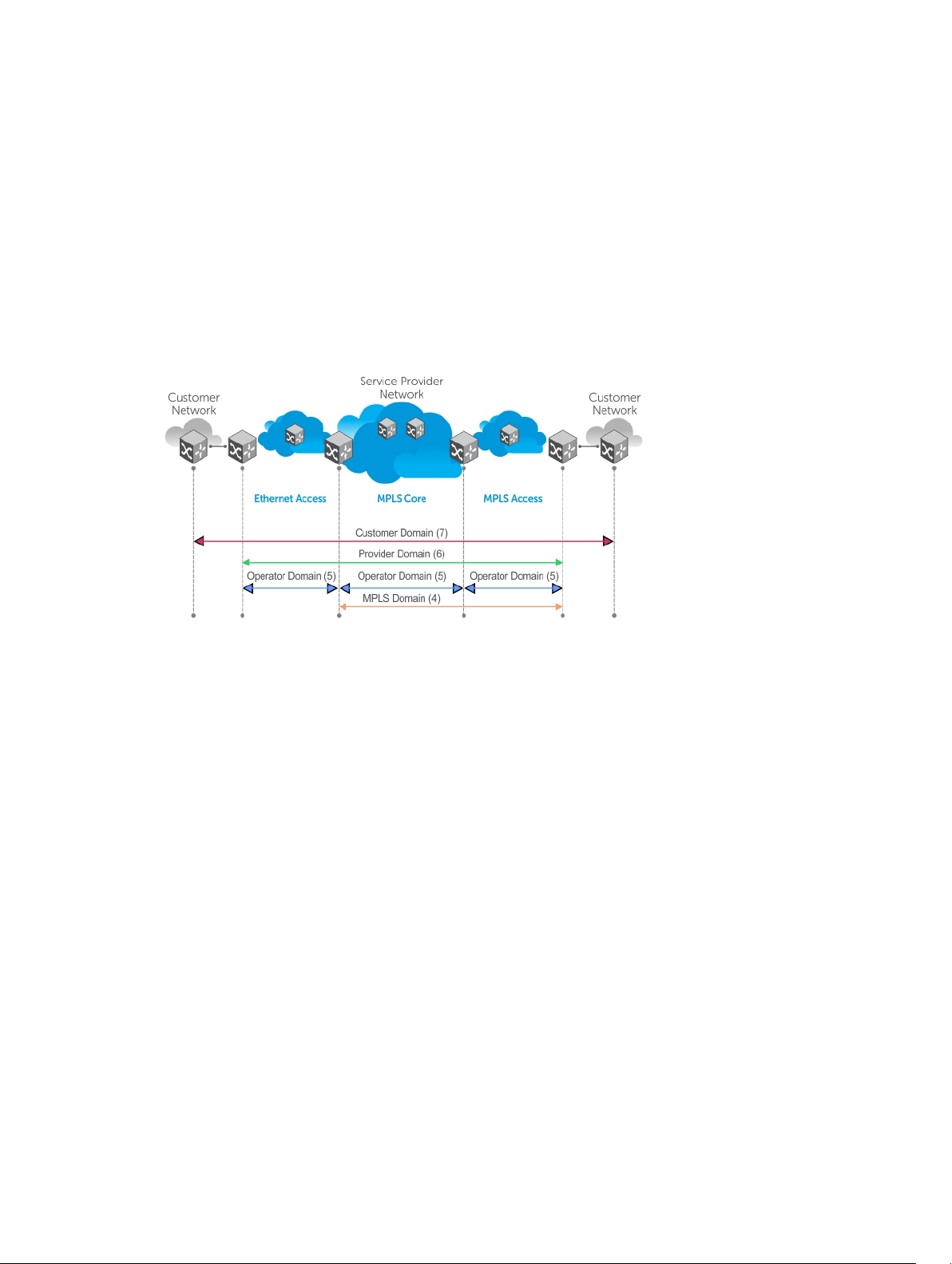
In addition to providing end-to-end OAM in native Layer 2 Ethernet Service Provider/Metro networks, you
can also use CFM to manage and troubleshoot any Layer 2 network including enterprise, datacenter, and
cluster networks.
Maintenance Domains
Connectivity fault management (CFM) divides a network into hierarchical maintenance domains, as
shown in the following illustration.
A CFM maintenance domain is a management space on a network that a single management entity owns
and operates. The network administrator assigns a unique maintenance level (from 0 to 7) to each
domain to define the hierarchical relationship between domains. Domains can touch or nest but cannot
overlap or intersect as that would require management by multiple entities.
Figure 3. OAM Domains
Maintenance Points
Domains are comprised of logical entities called maintenance points.
A maintenance point is an interface demarcation that confines CFM frames to a domain. There are two
types of maintenance points:
• Maintenance end points (MEPs) — a logical entity that marks the end point of a domain.
• Maintenance intermediate points (MIPs) — a logical entity configured at a port of a switch that is an
intermediate point of a maintenance entity (ME). An ME is a point-to-point relationship between two
MEPs within a single domain. MIPs are internal to a domain, not at the boundary, and respond to CFM
only when triggered by linktrace and loopback messages. You can configure MIPs to snoop continuity
check Messages (CCMs) to build a MIP CCM database.
These roles define the relationships between all devices so that each device can monitor the layers under
its responsibility. Maintenance points drop all lower-level frames and forward all higher-level frames.
802.1ag
89
Page 90

Figure 4. Maintenance Points
Maintenance End Points
A maintenance end point (MEP) is a logical entity that marks the end point of a domain.
There are two types of MEPs defined in 802.1ag for an 802.1 bridge:
• Up-MEP — monitors the forwarding path internal to a bridge on the customer or provider edge. On
Dell Networking systems, the internal forwarding path is effectively the switch fabric and forwarding
engine.
• Down-MEP — monitors the forwarding path external another bridge.
Configure Up-MEPs on ingress ports, ports that send traffic towards the bridge relay. Configure DownMEPs on egress ports, ports that send traffic away from the bridge relay.
Figure 5. Maintenance End Points
90
802.1ag
Page 91

Implementation Information
Because the S5000 has a single MAC address for all physical/LAG interfaces, only one MEP is allowed per
MA (per VLAN or per MD level).
Configuring the CFM
To configure the CFM, follow these steps:
1. Configure the ecfmacl CAM region using the cam-acl command. Refer to Configure Ingress ACLs.
2. Enabling Ethernet CFM
3. Creating a Maintenance Domain
4. Creating a Maintenance Association
5. Create Maintenance Points
6. Use CFM tools:
a. Continuity Check Messages
b. Sending Loopback Messages and Responses
c. Sending Linktrace Messages and Responses
Related Configuration Tasks
• Enabling CFM SNMP Traps
• Displaying Ethernet CFM Statistics
Enabling Ethernet CFM
To enable the Ethernet CFM, use the following tasks.
1. Spawn the CFM process. No CFM configuration is allowed until the CFM process is spawned.
CONFIGURATION mode
ethernet cfm
2. Disable Ethernet CFM without stopping the CFM process.
ETHERNET CFM
disable
Creating a Maintenance Domain
Connectivity fault management (CFM) divides a network into hierarchical maintenance domains, as
shown in Maintenance Domains.
1. Create maintenance domain.
ETHERNET CFM mode
domain name md-level number
802.1ag
91
Page 92

The range is from 0 to 7.
2. Display maintenance domain information.
EXEC Privilege mode
show ethernet cfm domain [name | brief]
Example of Viewing Configured Maintenance Domains
Dell# show ethernet cfm domain
Domain Name: customer
Level: 7
Total Service: 1
Services
MA-Name VLAN CC-Int X-CHK Status
My_MA 200 10s enabled
Domain Name: praveen
Level: 6
Total Service: 1
Services
MA-Name VLAN CC-Int X-CHK Status
Your_MA 100 10s enabled
Creating a Maintenance Association
A maintenance association (MA) is a subdivision of an MD that contains all managed entities
corresponding to a single end-to-end service, typically a virtual area network (VLAN).
An MA is associated with a VLAN ID.
• Create maintenance association.
ECFM DOMAIN mode
service name vlan vlan-id
Create Maintenance Points
Domains are comprised of logical entities called maintenance points. A maintenance point is an interface
demarcation that confines CFM frames to a domain.
There are two types of maintenance points:
• Maintenance End Points (MEPs) — a logical entity that marks the end point of a domain.
• Maintenance Intermediate Points (MIPs) — a logical entity configured at a port of a switch that
constitutes intermediate points of a Maintenance Entity (ME). An ME is a point-to-point relationship
between two MEPs within a single domain.
These roles define the relationships between all devices so that each device can monitor the layers under
its responsibility.
Creating a Maintenance End Point
A maintenance endpoint (MEP) is a logical entity that marks the endpoint of a domain.
There are two types of MEPs defined in 802.1ag for an 802.1 bridge:
92
802.1ag
Page 93

• Up-MEP — monitors the forwarding path internal to a bridge on the customer or provider edge. On
Dell Networking systems, the internal forwarding path is effectively the switch fabric and forwarding
engine.
• Down-MEP — monitors the forwarding path external another bridge.
Configure Up-MEPs on ingress ports, ports that send traffic towards the bridge relay. Configure DownMEPs on egress ports, ports that send traffic away from the bridge relay.
1. Create an MEP.
INTERFACE mode
ethernet cfm mep {up-mep | down-mep} domain {name | level } ma-name name
mepid mep-id
The range is from 1 to 8191.
2. Display configured MEPs and MIPs.
EXEC Privilege mode
show ethernet cfm maintenance-points local [mep | mip]
Dell#show ethernet cfm maintenance-points local mep
---------------------------------------------------------------
MPID Domain Name Level Type Port CCM-Status
MA Name VLAN Dir MAC
----------------------------------------------------------------
100 cfm0 7 MEP Te 4/10 Enabled
test0 10 DOWN 00:01:e8:59:23:45
200 cfm1 6 MEP Te 4/10 Enabled
test1 20 DOWN 00:01:e8:59:23:45
300 cfm2 5 MEP Te 4/10 Enabled
test2 30 DOWN 00:01:e8:59:23:45
Creating a Maintenance Intermediate Point
Maintenance intermediate point (MIP) is a logical entity configured at a port of a switch that constitutes
intermediate points of a maintenance entity (ME).
An ME is a point-to-point relationship between two MEPs within a single domain. An MIP is not
associated with any MA or service instance, and it belongs to the entire MD.
1. Create a MIP.
INTERFACE mode
ethernet cfm mip domain {name | level } ma-name name
2. Display configured MEPs and MIPs.
EXEC Privilege mode
show ethernet cfm maintenance-points local [mep | mip]
Example of Viewing Configured MIPs
Dell#show ethernet cfm maintenance-points local mip
--------------------------------------------------------------------
MPID Domain Name Level Type Port CCM-Status
MA Name VLAN Dir MAC
---------------------------------------------------------------------
0 service1 4 MIP Te 0/5 Disabled
My_MA 3333 DOWN 00:01:e8:0b:c6:36
802.1ag
93
Page 94

0 service1 4 MIP Te 0/5 Disabled
Your_MA 3333 UP 00:01:e8:0b:c6:36
Displaying the MP Databases
CFM maintains two MP databases:
• MEP Database (MEP-DB) — Every MEP must maintain a database of all other MEPs in the MA that have
announced their presence via CCM.
• MIP Database (MIP-DB) — Every MIP must maintain a database of all other MEPs in the MA that have
announced their presence via CCM.
To display the MEP and MIP databases, use the following commands.
• Display the MEP Database.
EXEC Privilege mode
show ethernet cfm maintenance-points remote detail [active | domain {level |
name} | expired | waiting]
• Display the MIP Database.
EXEC Privilege mode
show ethernet cfm mipdb
Example of Displaying the MEP Database
Dell#show ethernet cfm maintenance-points remote detail
MAC Address: 00:01:e8:58:68:78
Domain Name: cfm0
MA Name: test0
Level: 7
VLAN: 10
MP ID: 900
Sender Chassis ID: Dell
MEP Interface status: Up
MEP Port status: Forwarding
Receive RDI: FALSE
MP Status: Active
Setting the MP Database Persistence
To set the database persistence, use the following command.
• Set the amount of time that data from a missing MEP is kept in the continuity check database.
ECFM DOMAIN mode
database hold-time minutes
The default is 100 minutes.
The range is from 100 to 65535 minutes.
94
802.1ag
Page 95

Continuity Check Messages
Continuity check messages (CCM) are periodic hellos.
Continuity check messages:
• discover MEPs and MIPs within a maintenance domain
• detect loss of connectivity between MEPs
• detect misconfiguration, such as VLAN ID mismatch between MEPs
• to detect unauthorized MEPs in a maintenance domain
CCMs are multicast Ethernet frames sent at regular intervals from each MEP. They have a destination
address based on the MD level (01:80:C2:00:00:3X where X is the MD level of the transmitting MEP from
0 to 7). All MEPs must listen to these multicast MAC addresses and process these messages. MIPs may
optionally process the CCM messages the MEPs originate and construct a MIP CCM database.
MEPs and MIPs filter CCMs from higher and lower domain levels as described in the following table.
Table 6. Continuity Check Message Processing
Frames at Frames from UP-MEP Action Down-MEP Action MIP Action
Less than my level Bridge-relay side or
Wire side
My level Bridge-relay side Consume Drop Add to MIP-DB and
My level Wire side Drop Consume Add to MIP-DB and
Greater than my
level
All the remote MEPs in the maintenance domain are defined on each MEP. Each MEP then expects a
periodic CCM from the configured list of MEPs. A connectivity failure is then defined as:
• Loss of three consecutive CCMs from any of the remote MEP, which indicates a network failure.
• Reception of a CCM with an incorrect CCM transmission interval, which indicates a configuration
error.
• Reception of a CCM with an incorrect MEP ID or MAID, which indicates a configuration or crossconnect error. This error could happen when different VLANs are cross-connected due to a
configuration error.
• Reception of a CCM with an MD level lower than the receiving MEP, which indicates a configuration
or cross-connect error.
• Reception of a CCM containing a port status/interface status TLV, which indicates a failed bridge or
aggregated port.
The continuity check protocol sends fault notifications (Syslogs, and SNMP traps, if enabled) whenever
you encounter any of these errors.
Bridge-relay side or
Wire side
Drop Drop Drop
forward
forward
Forward Forward Forward
802.1ag
95
Page 96

Enabling CCM
To enable CCM, use the following commands.
1. Enable CCM.
ECFM DOMAIN mode
no ccm disable
The default is Disabled.
2. Configure the transmit interval (mandatory). The interval specified applies to all MEPs in the domain.
ECFM DOMAIN mode
ccm transmit-interval seconds
The default is 10 seconds.
Enabling Cross-Checking
To enable cross-checking, use the following commands.
1. Enable cross-checking.
ETHERNET CFM mode
mep cross-check enable
The default is Disabled.
2. Start the cross-check operation for an MEP
ETHERNET CFM mode
mep cross-check mep-id
3. Configure the amount of time the system waits for a remote MEP to come up before the cross-
check operation is started.
ETHERNET CFM mode
mep cross-check start-delay number
Sending Loopback Messages and Responses
Loopback message and response (LBM, LBR), also called Layer 2 Ping, is an administrative echo
transmitted by MEPs to verify reachability to another MEP or MIP within the maintenance domain. LBM
and LBR are unicast frames.
• Send a Loopback message
EXEC Privilege mode
ping ethernet domain name ma-name ma-name remote {mep-id | mac-addr macaddress} source {mep-id | port interface}
96
802.1ag
Page 97

Sending Linktrace Messages and Responses
Linktrace message and response (LTM, LTR), also called Layer 2 Traceroute, is an administratively sent
multicast frame transmitted by MEPs to track, hop-by-hop, the path to another MEP or MIP within the
maintenance domain.
All MEPs and MIPs in the same domain respond to an LTM with a unicast LTR. Intermediate MIPs forward
the LTM toward the target MEP.
Figure 6. MPLS Core
Link trace messages carry a unicast target address (the MAC address of an MIP or MEP) inside a multicast
frame. The destination group address is based on the MD level of the transmitting MEP
(01:80:C2:00:00:3[8 to F]). The MPs on the path to the target MAC address reply to the LTM with an LTR,
and relays the LTM towards the target MAC until the target MAC is reached or TTL equals 0.
• Send a Linktrace message. Because the LTM is a Multicast message sent to the entire ME, there is no
need to specify a destination.
EXEC Privilege
traceroute ethernet domain
Caching Link Trace
After you execute a Link Trace command, the trace information can be cached so that you can view it
later without retracing.
To enable, set, display, and delete link trace caching, use the following commands.
• Enable Link Trace caching.
CONFIGURATION mode
traceroute cache
802.1ag
97
Page 98

• Set the amount of time a trace result is cached.
ETHERNET CFM mode
traceroute cache hold-time minutes
The default is 100 minutes.
The range is from 10 to 65535 minutes.
• Set the size of the Link Trace Cache.
ETHERNET CFM mode
traceroute cache size entries
The default is 100.
The range is from 1 to 4095 entries.
• Display the Link Trace Cache.
EXEC Privilege mode
show ethernet cfm traceroute-cache
• Delete all Link Trace Cache entries.
EXEC Privilege mode
clear ethernet cfm traceroute-cache
Example of Viewing the Link Trace Cache
Dell#show ethernet cfm traceroute-cache
Traceroute to 00:01:e8:52:4a:f8 on Domain Customer2, Level 7, MA name Test2
with VLAN 2
------------------------------------------------------------------------------
Hops Host IngressMAC Ingr Action Relay Action
Next Host Egress MAC Egress Action FWD Status
------------------------------------------------------------------------------
4 00:00:00:01:e8:53:4a:f8 00:01:e8:52:4a:f8 IngOK RlyHit
00:00:00:01:e8:52:4a:f8 Terminal MEP
Enabling CFM SNMP Traps
An SNMP trap is sent only when one of the five highest priority defects occur.
Table 7. Five Highest Priority Defects
Priority Defects Trap Message
Cross-connect defect
Error-CCM defect
%ECFM-5-ECFM_XCON_ALARM: Cross connect
fault detected by MEP 1 in Domain
customer1 at Level 7 VLAN 1000
%ECFM-5-ECFM_ERROR_ALARM: Error CCM
Defect detected by MEP 1 in Domain
customer1 at Level 7 VLAN 1000
98
802.1ag
Page 99

Priority Defects Trap Message
MAC Status defect
%ECFM-5-ECFM_MAC_STATUS_ALARM: MAC
Status Defect detected by MEP 1 in
Domain provider at Level 4 VLAN 3000
Remote CCM defect
%ECFM-5-ECFM_REMOTE_ALARM: Remote CCM
Defect detected by MEP 3 in Domain
customer1 at Level 7 VLAN 1000
RDI defect
%ECFM-5-ECFM_RDI_ALARM: RDI Defect
detected by MEP 3 in Domain customer1
at Level 7 VLAN 1000
Three values are given within the trap messages: MD Index, MA Index, and MPID. You can reference these
values against the output of the show ethernet cfm domain and show ethernet cfm
maintenance-points local mep commands
To enable CFM SNMP traps, use the following command.
• Enable SNMP trap messages for Ethernet CFM.
CONFIGURATION mode
snmp-server enable traps ecfm
Example of Viewing CFM SNMP Trap Information
Dell#show ethernet cfm maintenance-points local mep
--------------------------------------------------------------------
MPID Domain Name Level Type Port CCM-Status
MA Name VLAN Dir MAC
---------------------------------------------------------------------
100 cfm0 7 MEP Gi 4/10 Enabled
test0 10 DOWN 00:01:e8:59:23:45
Dell(conf-if-gi-0/6)#do show ethernet cfm domain
Domain Name: My_Name
MD Index: 1
Level: 0
Total Service: 1
Services
MA-Index MA-Name VLAN CC-Int X-CHK Status
1 test 0 1s enabled
Domain Name: Your_Name
MD Index: 2
Level: 2
Total Service: 1
Services
MA-Index MA-Name VLAN CC-Int X-CHK Status
1 test 100 1s enabled
802.1ag
99
Page 100

Displaying Ethernet CFM Statistics
To display Ethernet CFM statistics, use the following commands.
• Display MEP CCM statistics.
EXEC Privilege mode
show ethernet cfm statistics [domain {name | level} vlan-id vlan-id mpid mpid
• Display CFM statistics by port.
EXEC Privilege mode
show ethernet cfm port-statistics [interface]
Example of Viewing CFM Statistics
Example of Viewing CFM Statistics by Port
Dell# show ethernet cfm statistics
Domain Name: Customer
Domain Level: 7
MA Name: My_MA
MPID: 300
CCMs:
Transmitted: 1503 RcvdSeqErrors: 0
LTRs:
Unexpected Rcvd: 0
LBRs:
Received: 0 Rcvd Out Of Order: 0
Received Bad MSDU: 0
Transmitted: 0
Dell#show ethernet cfm port-statistics interface tengigabitethernet 0/5
Port statistics for port: Te 0/5
==================================
RX Statistics
=============
Total CFM Pkts 75394 CCM Pkts 75394
LBM Pkts 0 LTM Pkts 0
LBR Pkts 0 LTR Pkts 0
Bad CFM Pkts 0 CFM Pkts Discarded 0
CFM Pkts forwarded 102417
TX Statistics
=============
Total CFM Pkts 10303 CCM Pkts 0
LBM Pkts 0 LTM Pkts 3
LBR Pkts 0 LTR Pkts 0
100
802.1ag
 Loading...