


Dell Networking S5000
Getting Started Guide
Handbuch zum Einstieg
Guía de introducción
Guide de mise en route
ךירדמ תליחת הדובע
Руководство по началу работы
Başlangıç Kılavuzu
Dell Networking S5000
Getting Started Guide
Notes, Cautions, and Warnings
NOTE: A NOTE indicates important information that helps you make better use of your
computer.
CAUTION: A CAUTION indicates either potential damage to hardware or loss of data and
tells you how to avoid the problem.
WARNING: A WARNING indicates a potential for property damage, personal injury, or
death.
© 2013 Dell Inc.
Trademarks used in this text:
Dell
™
, the Dell logo,
Dell Boomi
™
,
Dell Precision
™
,
OptiPlex
™
,
Latitude
™
,
PowerEdge
™
,
PowerVault
™
,
PowerConnect
™
,
OpenManage
™
,
EqualLogic
™
,
Compellent
™
,
KACE
™
,
FlexAddress
™
,
Force10
™
and
Vostro
™
are trademarks of Dell Inc.
Intel
®
,
Pentium
®
,
Xeon
®
,
Core
®
and
Celeron
®
are registered trademarks of Intel Corporation in the U.S. and other countries.
AMD
®
is a
registered trademark and
AMD Opteron
™
,
AMD Phenom
™
and
AMD Sempron
™
are trademarks of
Advanced Micro Devices, Inc.
Microsoft
®
,
Windows
®
,
Windows Server
®
,
Internet Explorer
®
,
MS-DOS
®
,
Windows Vista
®
and
Active Directory
®
are either trademarks or registered trademarks of Microsoft
Corporation in the United States and/or other countries. Red Hat® and Red Hat® Enterprise Linux® are
registered trademarks of Red Hat, Inc. in the United States and/or other countries. Novell® and SUSE® are
registered trademarks of Novell Inc. in the United States and other countries. Oracle® is a registered
trademark of Oracle Corporation and/or its affiliates. Citrix®, Xen®, XenServer® and XenMotion® are either
registered trademarks or trademarks of Citrix Systems, Inc. in the United States and/or other countries.
VMware®, Virtual SMP®, vMotion®, vCenter® and vSphere® are registered trademarks or trademarks of
VMware, Inc. in the United States or other countries. IBM® is a registered trademark of International
Business Machines Corporation.
2013 - 03
Rev. A00
Getting Started Guide
This document is intended as a Getting Started Guide to get new systems up and running
and ready for configuration. For complete installation and configuration information,
refer to the documents listed below:
Table 1. S5000 Documents
Information Documentation
Hardware installation and power-up
instructions
Installing the S5000 Switch
Software configuration
FTOS Configuration Guide for the S5000
Switch
Command line interface
FTOS Command Line Reference Guide for
the S5000 Switch
Latest updates
FTOS Release Notes for the S5000 Switch
Introduction
This document provides basic information about the S5000 switch, including how to
install the switch and perform the initial configuration.
For information about how to configure and monitor switch features, refer to the
FTOS
Configuration Guide for the S5000 Switch
, which is available on the Dell Support website
at
http://www.dell.com/support/manuals
.
Product Description
The S5000 is part of Dell Networking's S-Series switches for Data Center Top of Rack
(ToR) switches.
The S5000 is purpose-built to provide architectural flexibility for unified and virtualized
environments. It is a 10G ToR solution that enables converged local area networks (LAN)
and storage area networks (SAN) in the same box. The S5000 delivers Fibre Channel over
Ethernet (FCoE) and Fibre Channel (FC) capability in a one rack unit (RU) ToR switch form
factor.
The S5000 supports Data Center Bridging (ETS/PFC/DCBX), FCoE Transit (FIP Snooping),
NPIV Proxy Gateway (NPG), and Internet small computer system interface (iSCSI)
storage traffic. The S5000 also provides aggregation and convergence functionality using
pluggable modules for flexible configuration.
3
Unpacking the Switch
The S5000 and its accessories are shipped in multiple boxes. Before unpacking the
switch, inspect the container and immediately report any evidence of damage. Verify
that you have received your ordered items. For example, if you order one S5000 switch,
the following items are included.
WARNING: If any item is missing or damaged, contact your Dell Networking
representative or reseller for instructions.
WARNING: Electrostatic discharge (ESD) damage can occur if components are
mishandled. Always wear an ESD-preventive wrist or heel ground strap when
handling the S5000 and its components.
• One S5000 switch
• Two Fans
• Two Power Supplies (either AC or DC)
• One rail kit (#1 and #2 Phillips screwdrivers required)
• Screws for rack installation
• Two to Four I/O Modules (according to order)
• Two Blanks
• One RJ-45 to DB-9 female cable
• Two AC or DC power cords for AC or DC units (country/region specific)
•
Getting Started Guide
•
Safety and Regulatory Information
•
Warranty and Support Information
•
Software License Agreement
1. Place the container on a clean, flat surface and cut all straps securing the
container.
2. Open the container or remove the container top.
3. Carefully remove all components from the container and place it on a secure and
clean surface.
4. Remove all packing material.
5. Inspect the switch and accessories for damage.
Important Points Before You Continue
• Identify the I/O and Utility panel on the chassis. The I/O panel has four fixed
40GbE ports on the right side of the panel, refer to Figure 1. The Utility panel has
4
the power supply slots, LEDs, and USB slots on the left side of the panel, refer to
Figure 3.
• Identify slots 0, 1, 2, and 3 on the I/O panel, refer to Figure 2. You can insert a
Fibre Channel module only in slot 0. You can install the Ethernet modules in slots
0, 1, 2, and 3.
• Identify slots 0, 1, 2, and 3 on the Utility panel, refer to Figure 3. You can insert
Power supply units (PSUs) only in slots 0 and 3. You can insert the Fan modules
in any of the slots.
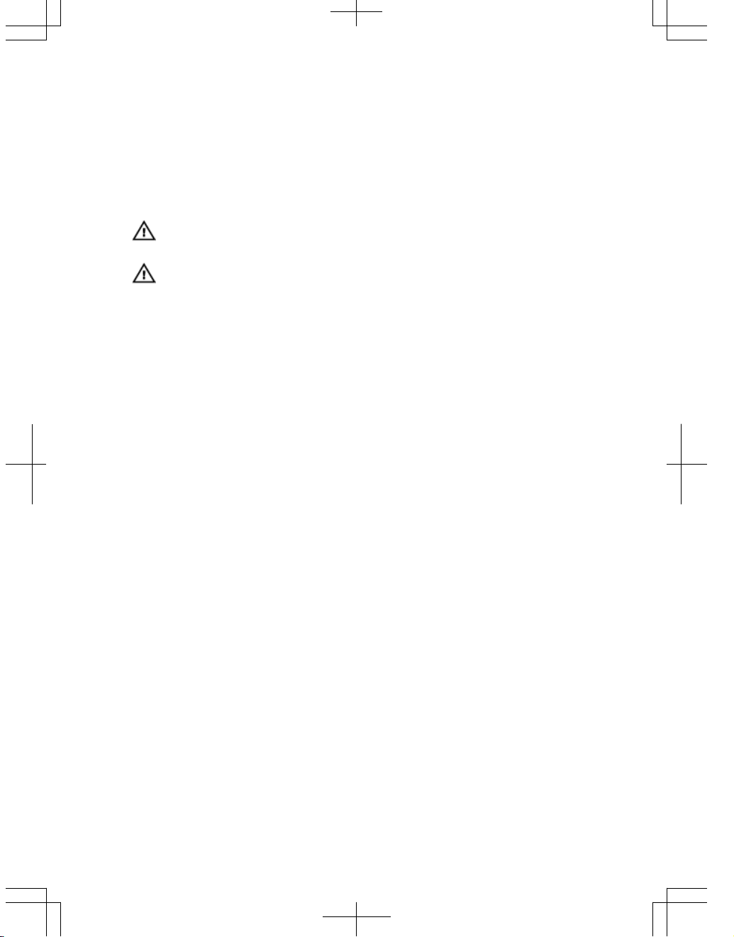
Figure 1. S5000 I/O and Utility Panels
1. I/O panel
2. Utility panel
3. Four 40GbE QSFP+ ports (each port ALSO supports 4 × 10GbE mode)
Hardware Installation Overview
To install the S5000, follow these steps:
1. Attach the mounting brackets.
2. Install the S5000 chassis into a 4–post rack or cabinet.
3. Ground the rack.
4. Install the Ethernet and/or Fibre Channel modules (Fibre Channel module must be
installed only in slot 0).
5
5. Install the power supplies.
6. Secure the power cables.
7. Install the fan modules.
8. Install the SFP+ and QSFP+ optics.
9. Supply power and power up the system.
Hardware Overview
This section contains information about device characteristics and modular hardware
configurations for the S5000.
The S5000 has the following physical dimensions:
• Height: 1.71 inches (43.5 mm)
• Width: 17.4 inches (441.9 mm)
• Depth: 28 inches (711.2 mm)
The S5000 has a chassis design with 640Gbps switching bandwidth.
The system also provides one DB9 RS-232 console port with YOST RJ-45 pinout and a
dedicated Ethernet service port for out-of-band (OOB) management functions.
I/O Panel
All fixed data ports (4 × 40GbE quad small form-factor pluggable plus [QSFP+] ports) and
the four slots for pluggable modules are on the I/O panel.
The I/O panel includes:
• Pluggable Modules
– 12-Port Ethernet Module (1G/10G speeds)
– 12-Port Fibre Channel Module (2G/4G/8G speeds)
• 4 × 40GbE QSFP+ Ports and light emitting diodes (LEDs)
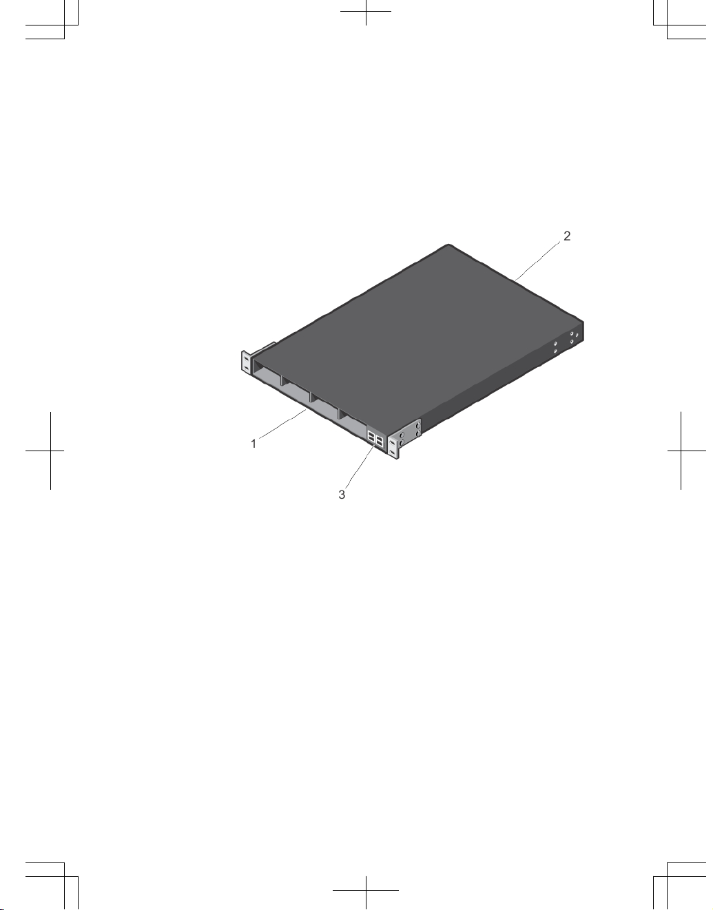
Figure 2. S5000 I/O Panel
6
1. Slot 0 (supports Ethernet and Fibre
Channel modules)
2. Slot 1 (supports only Ethernet
modules)
3. Slot 2 (supports only Ethernet
modules)
4. Slot 3 (supports only Ethernet
modules)
5. Four 40GbE QSFP+ ports (each port
ALSO supports 4 × 10GbE mode)
NOTE: The LED displays for the system status are on both sides of the chassis. The
fan and power status LEDs are on the Utility panel.
Utility Panel
The Utility panel side of the platform contains the fan and power modules.
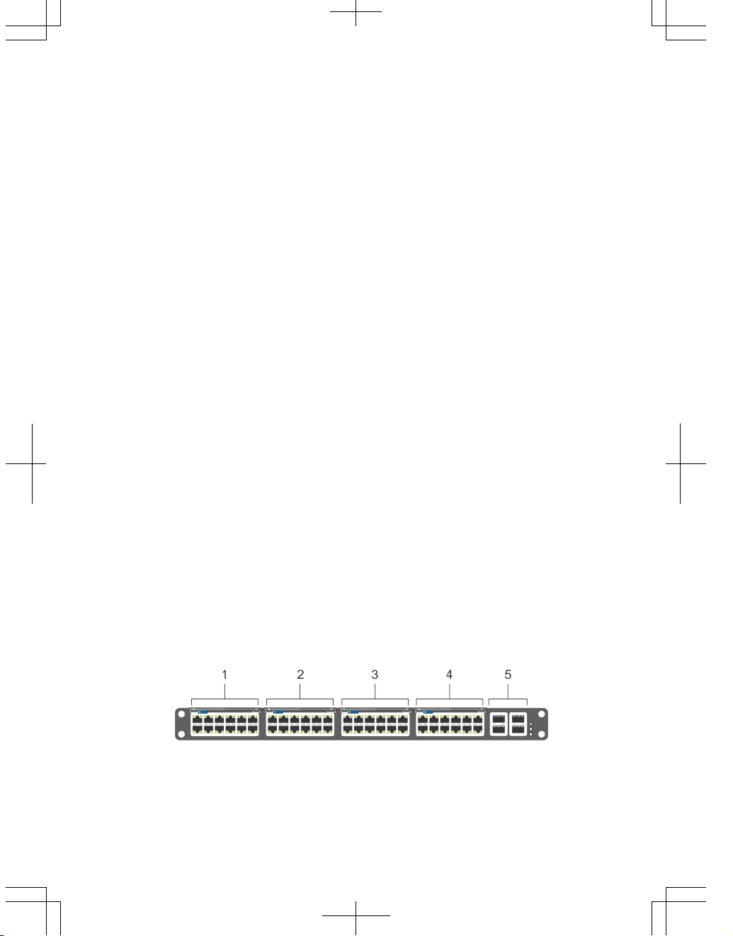
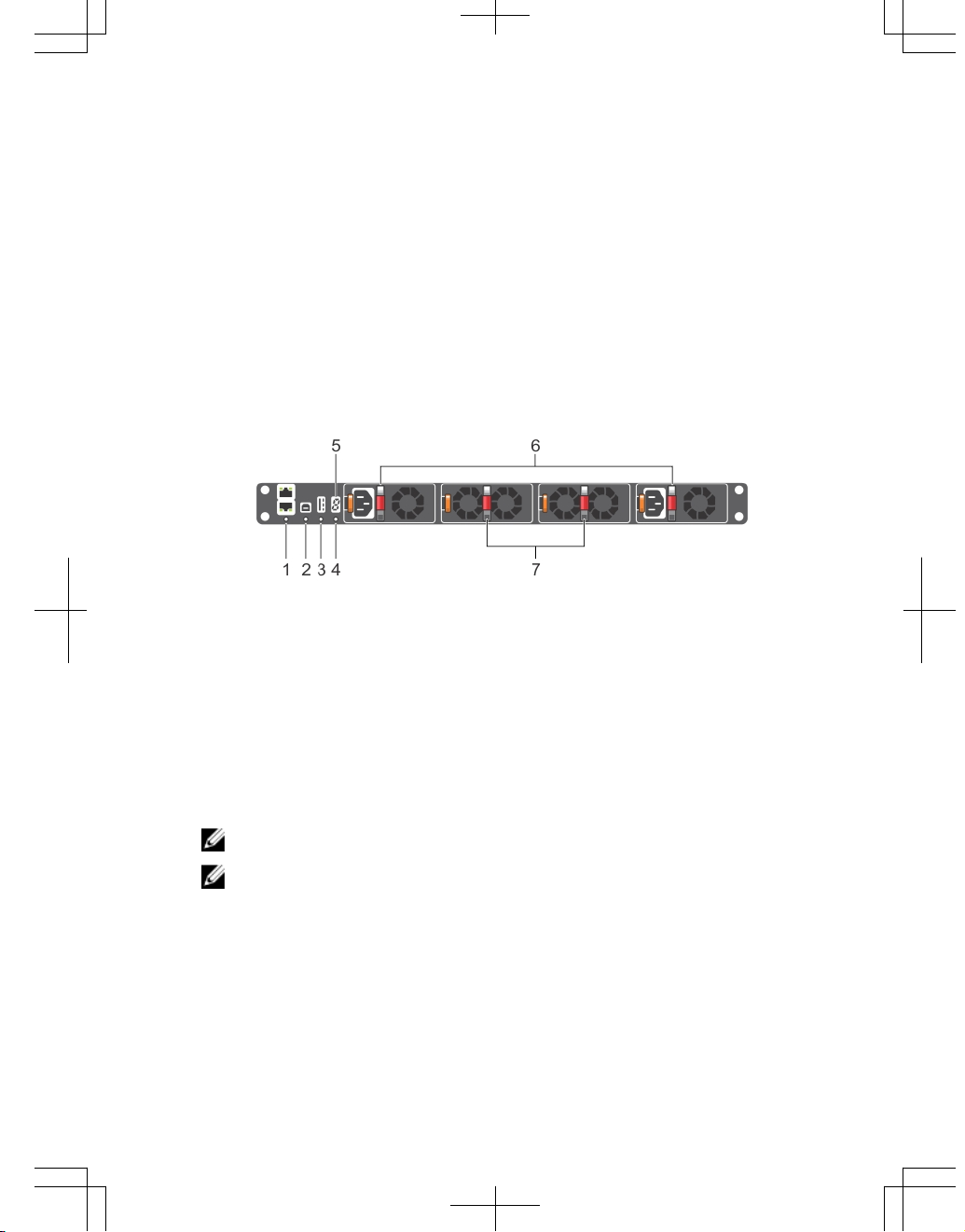
Figure 3. S5000 Power Supplies and Fan Modules
1. Slot 0 (for PSU 0)
2. Slot 1 (for Fan Module 0)
3. Slot 2 (for Fan Module 1)
4. Slot 3 (for PSU 1)
5. Grab Handles
Power Supplies
The S5000 supports two hot-swappable PSUs.
NOTE: The PSUs must be installed at the customer site.
The S5000 has SKUs that support the following configurations:
• AC PSU with fan airflow from I/O to Utility
• AC-R PSU with fan airflow from Utility to I/O
• DC PSU with fan airflow from I/O to Utility
• DC-R PSU with fan airflow from Utility to I/O
PSUs are field replaceable. To ensure power redundancy and adequate cooling, install
two power supplies in the switch. When running with full redundancy (two PSUs
7
installed and running), you can remove and replace one PSU while the other PSU is
running without disrupting traffic.
Fans
The S5000 supports two fan trays with airflow directions from I/O to Utility or Utility to I/O.
Do not mix I/O to Utility and Utility to I/O airflows in a single S5000 chassis. All fans and
PSUs in a configuration must be in the same airflow direction. If you create a mixed
airflow configuration, the software notifies you of the invalid configuration.
The fans must be installed at the customer site.
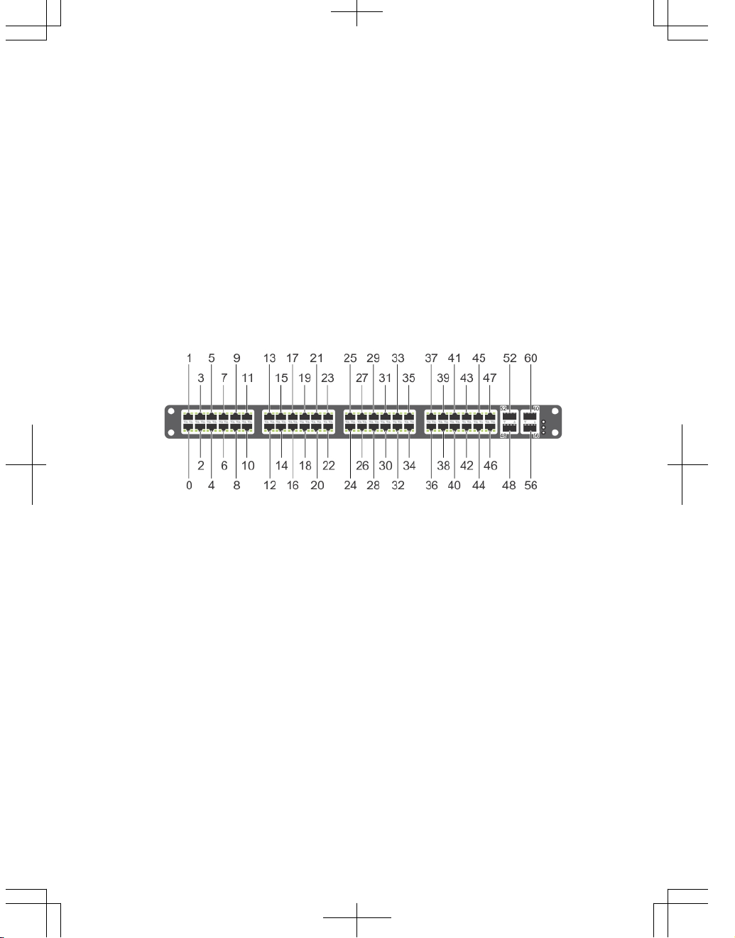
Port Numbering Convention
Even-numbered ports are at the bottom of the I/O panel and for modules odd-numbered
ports are at the top of the I/O panel.
Figure 4. Port Numbering
The previous figure shows the fixed four 40GbE data ports (ports 48, 52, 56, and 60) and
the four slots for pluggable modules on the S5000 I/ O panel. You can also use the 40GbE
ports in 4 × 10GbE mode.
The S5000 supports the following possible modules:
• 12-Port Ethernet Module (1G/10G speeds) (slot 0, 1, 2, or 3)
• 12-Port Fibre Channel Module (2G/4G/8G speeds) (slot 0)
The valid slot numbers are stack-unit numbers (from 0 to 11). The valid port numbers for
each interface type are:
• 1GbE: Ports 0 to 47
• 10GbE: Ports 0 to 63
• 40GbE: Ports 48, 52, 56, and 60
• Fibre Channel: Ports 0 to 11
8
• Management: Port 0
System Status
You can view S5000 status information in several ways, including LEDs and through the
CLI
show commands and with simple network management protocol (SNMP).
For more information about these options, refer to the
FTOS Command Line Reference
Guide
and
FTOS Configuration Guide for the S5000 Switch
.
As shown in the following figure, the S5000 includes LED displays on the I/O and Utility
side of the chassis. When the S5000 powers up or reloads, the status LED on the power
supplies are solid green.
The following table lists the LED definitions for the S5000 system.
Figure 5. System LEDs (Utility Panel) (AC Power Supplies installed)
1. Locator beacon LED
2. Alarm LED
3. System status LED
4. Master LED
5. Seven–segment display to identify
Stack ID
6. PSU status LED
7. Fan status LED
NOTE: For AC PSUs, an illuminated translucent handle indicates the power status.
NOTE: For DC PSUs, the power status LED is on the upper-left corner.
9
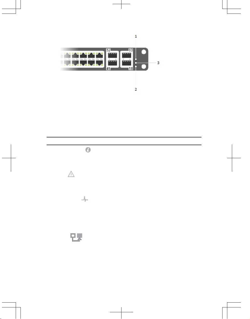
Figure 6. System LEDs (I/O Panel)
1. Locator beacon LED
2. Alarm LED
3. System status LED
Table 2. System LED Displays (Utility and I/O Panel)
Label LED Color/Display Description
Locator beacon LED
• Off
• Blue
• No activity
• System beacon/
locator
Alarm LED
• Off
• Amber solid
• Red solid
• No alarm
• Minor alarm
• Critical alarm
System status LED
• Off
• Green solid
• Green blinking
• Amber solid
• No power
• Normal operation
• System is booting
• System in card
problem state
Master LED
• Green solid
• Green blinking
• Off
• Switch in Stacking
Master mode OR
Switch in
Standalone mode
• Switch in Stacking
Standby mode
10
Label LED Color/Display Description
• Switch in Stacking
Member mode
PSU status LED
• Green solid
• Off
• Normal operation
• Power not present
Fan status LED
• Green solid
• Off
• Normal operation
• Power not present
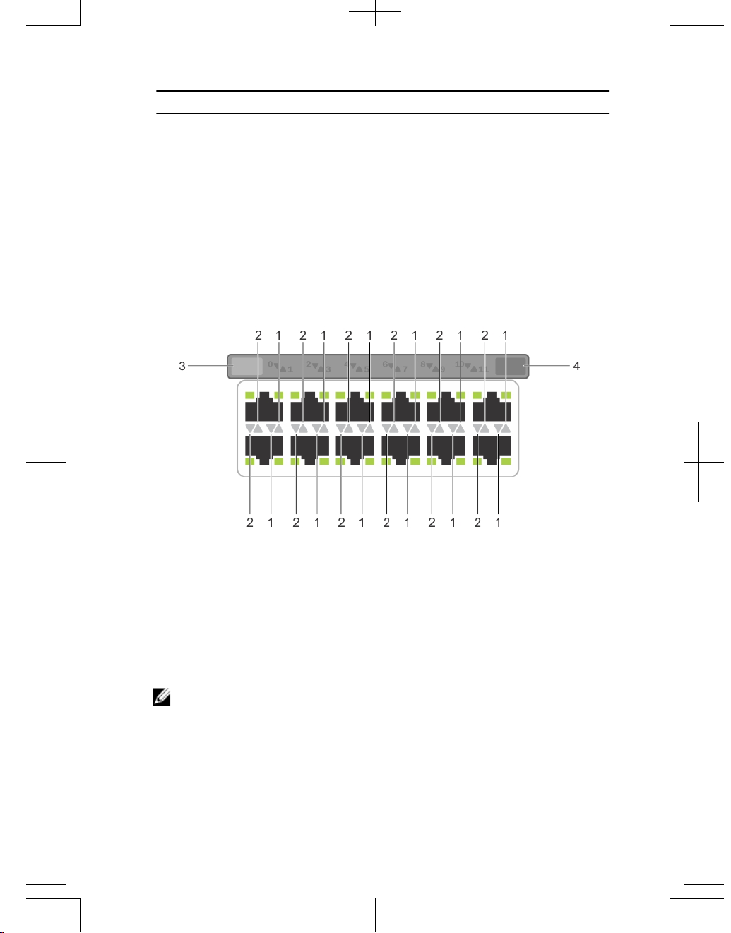
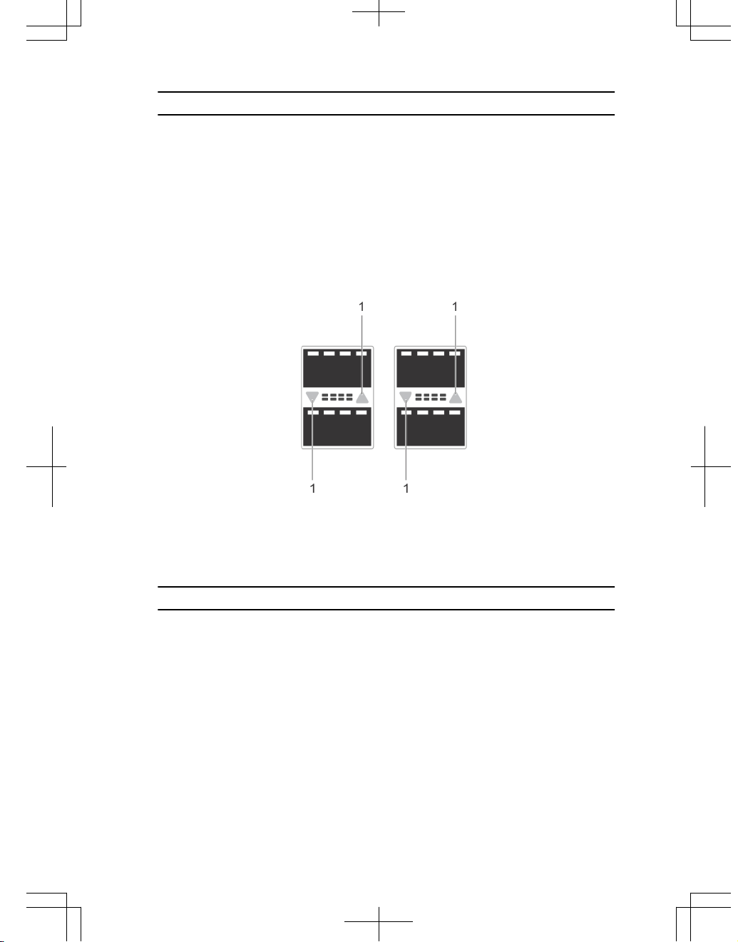
Figure 7. Module LEDs
1. Port locator beacon LED
2. Port link/activity LED
3. Module locator beacon LED
4. Module status LED
NOTE: The downward and upward pointing triangles denote the lower and upper
port LEDs respectively.
11
Table 3. Ethernet Port/Module LEDs
Label LED Color/Display Description
Port locator beacon LED
• Off
• Blue
• No activity
• Port beacon/
locator
Port link/activity LED
• Off
• Green solid
• Green blinking
• No link or interface
disabled
• Link present and
interface enabled
(Ethernet module)
• Port has activity
Module locator beacon LED
• Off
• Blue
• No activity
• Module beacon/
locator
Module status LED
• Off
• Green solid
• Yellow
• Module is not
powered up
• Module is powered
up
• Problem detected
with module
Table 4. Fibre Channel Port/Module LEDs
Label LED Color/Display Description
Port locator beacon LED
• Off
• Blue
• Green
• No activity
• Port beacon/
locator
• Fibre Channel mode
enabled
Port link/activity LED
• Off
• Green solid
• Green blinking
• No link or interface
disabled
• Link present and
interface enabled
• Port has activity
Module locator beacon LED
• Off • No activity
12
Label LED Color/Display Description
• Green
• Module beacon/
locator
Module status LED
• Off
• Green solid
• Yellow
• Module is not
powered up
• Module is powered
up
• Problem detected
with module
Figure 8. QSFP+ Port LEDs
1. Port link/activity LED
Table 5. 40GbE Port/Module LEDs
Label LED Color/Display Description
Port link/activity LED
• Off
• Green solid
• Green blinking
• No link or interface
disabled
• Link present and
interface enabled
• Port has activity
Installation
Before installing the switch, verify that you meet these guidelines:
13
• Enough clearance to the front of the switch so you can read the LEDs.
• AC/DC power cord reaches from the power outlet to the Utility-panel connector.
• Switch is rack-mounted before you install the power supply modules.
• Cabling is away from sources of electrical noise, such as radios, power lines,
and fluorescent lighting. Make sure that the cabling is safely away from other
devices that might damage the cables. If needed, allow one RU space between
devices to provide room for cabling.
• Airflow around the switch and through the vents is unrestricted.
• Temperature around the unit does not exceed 104°F (40°C). If the switch is in a
closed or multirack assembly, the temperature might be higher than normal room
temperature.
• Humidity around the switch does not exceed 85 percent.
• Altitude at the installation site is below 6600 feet.
• Switch is installed in an environment as free as possible from dust and foreign
conductive material (such as metal flakes from construction activities). Cooling
mechanisms, such as fans and blowers in the switch, can draw dust and other
particles causing contaminant buildup inside the chassis, which can result in
system malfunction.
Install the S5000 Chassis in a Rack or Cabinet
To install the S5000 system, Dell Networking recommends completing the
installation procedures in the order presented here.
NOTE: Always handle the system and its components with care. Avoid dropping the
S5000 chassis or its field replaceable units.
NOTE: For proper ventilation, position the S5000 chassis in an equipment rack (or
cabinet) with a minimum of 5 inches (12.7 cm) of clearance around exhaust vents.
The acceptable ambient temperature ranges are listed in the
Environmental
Parameters
section.
CAUTION: Always wear an ESD-preventive wrist or heel ground strap when
handling the S5000 and its components. As with all electrical devices of this type,
take all necessary safety precautions to prevent injury when installing this system.
ESD damage can occur if components are mishandled.
14
Attaching the Mounting Brackets
The S5000 is shipped with mounting brackets (rack ears) and the required screws (eight
screws) for rack or cabinet installation. The brackets are enclosed in a package with the
chassis.
1. Take the brackets and screws out of their packaging.
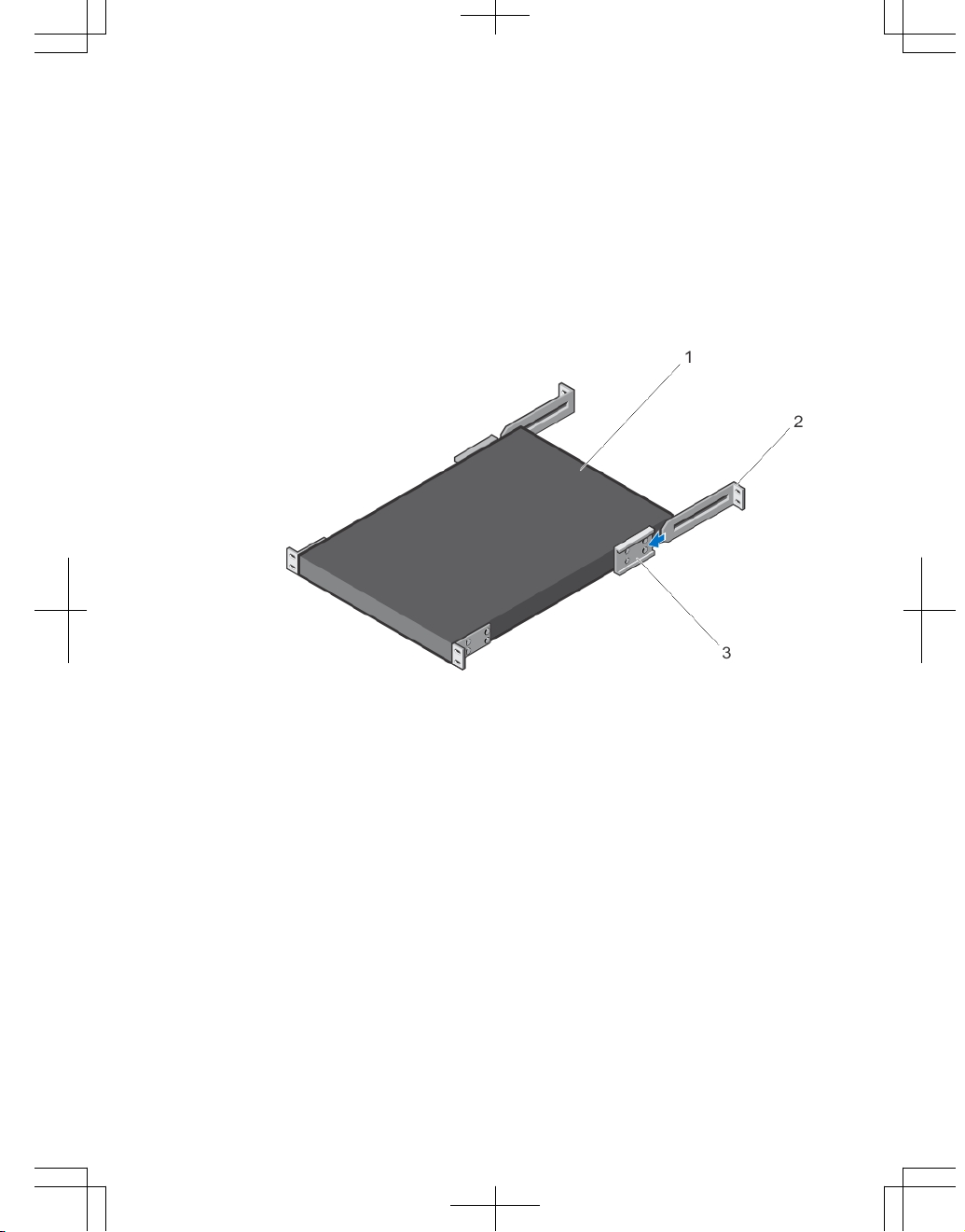
2. Slide the mounting brackets, as shown in the following figure.
Figure 9. Slide the mounting brackets
1. Utility side of the chassis
2. Mounting Bracket
3. Holding Bracket (factory installed)
Rack Mounting Safety Considerations
You may either place the switch on the rack shelf or mount the switch directly into a 19"
wide, EIA-310-E- compliant rack.
• Rack loading — Overloading or uneven loading of racks may result in shelf or
rack failure, which may damage equipment and cause possible personal injury.
Stabilize racks in a permanent location before loading begins. Mount the
components beginning at the bottom of the rack, then work to the top. Do not
exceed your rack load rating.
15
• Power considerations — Connect only to the power source specified on the unit.
When multiple electrical components are installed in a rack, ensure that the total
component power ratings do not exceed the circuit capabilities. Overloaded
power sources and extension cords present fire and shock hazards.
• Elevated ambient temperature — If installed in a closed rack assembly, the
operating temperature of the rack environment may be greater than the room
ambient temperature. Use care not to exceed the 40°C maximum ambient
temperature of the switch.
• Reduced air flow — Install the equipment in the rack so that the amount of
airflow required for safe operation of the equipment is not compromised.
• Reverse air flow — Necessary clearance is required to ensure cool air intake
and to avoid hot air blow out from I/O panel.
• Reliable earthing — Maintain reliable earthing of rack-mounted equipment. Pay
particular attention to the supply connections other than the direct connections
to the branch circuit; for example, use of power strips.
• Do not mount the equipment with the Utility panel facing in the downward
position.
WARNING: These instructions are a condensed reference. Read the safety
instructions in your Safety, Environmental, and Regulatory information booklet
before you begin.
NOTE: The illustrations in this document are not intended to represent a specific
switch.
Installing the S5000 Chassis into a 4-Post Rack or Cabinet
NOTE: Dell Networking recommends that one person hold the S5000 chassis in
place while a second person attaches the brackets to the posts.
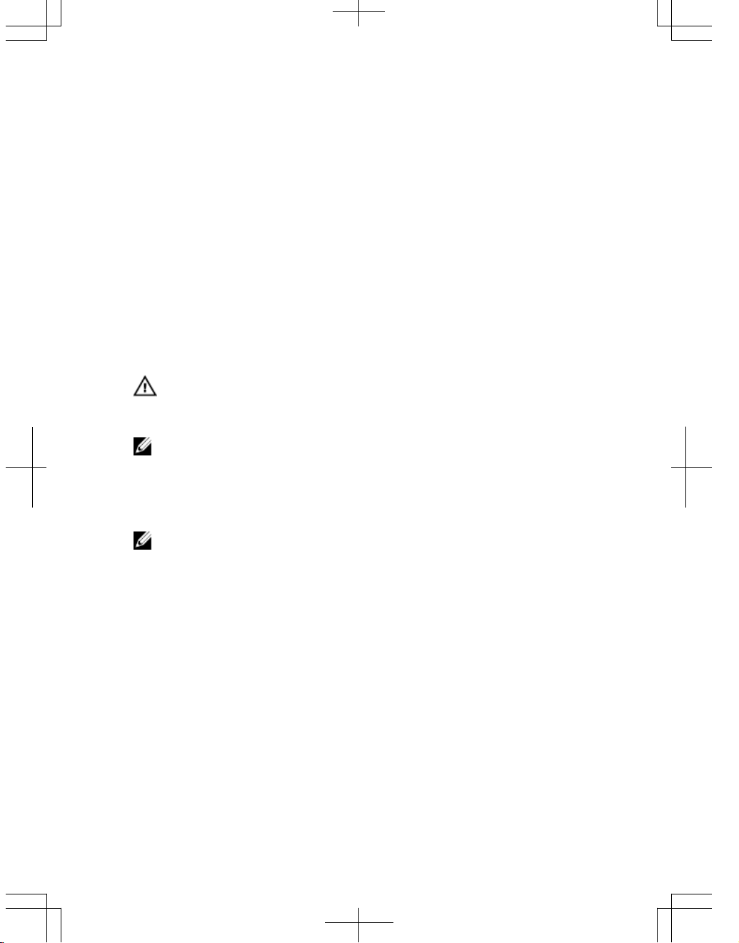
Attach the bracket "ears" to the rack or cabinet posts, using two screws for each
bracket. Ensure the screws are tightened firmly.
16
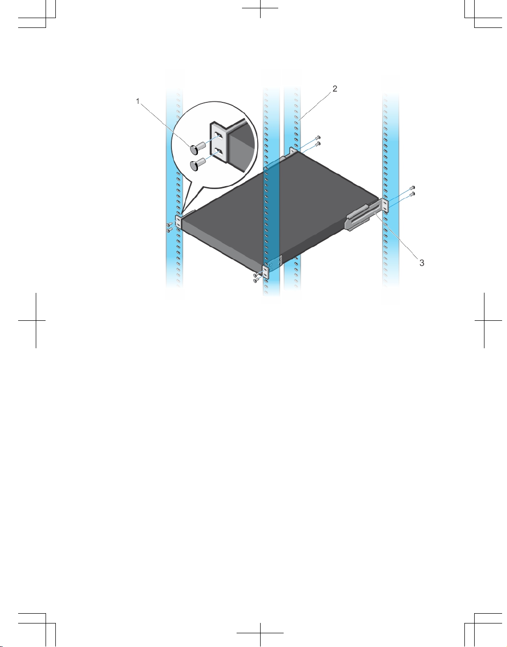
Figure 10. Front Rack Installation
1. Screws
2. 4–Post Rack or Cabinet
3. Mounting Bracket
Rack Grounding
When you prepare your equipment rack, ensure that the rack is earth ground. You must
ground the equipment rack to the same ground point the power service uses in your
area. The ground path must be permanent.
Important Points to Remember for Installing an Ethernet Module
• Installing and swapping of Ethernet modules must be done BEFORE power up. If
you need to install or replace a module, power down the system before you
install or replace it. If you install or replace a module when the system is
powered up, the system does not recognize the module. Online insertion of
modules can result in a catastrophic failure.
17
WARNING: Electrostatic discharge (ESD) damage can occur if components are
mishandled. Always wear an ESD-preventive wrist or heel ground strap when
handling the S5000 and its components.
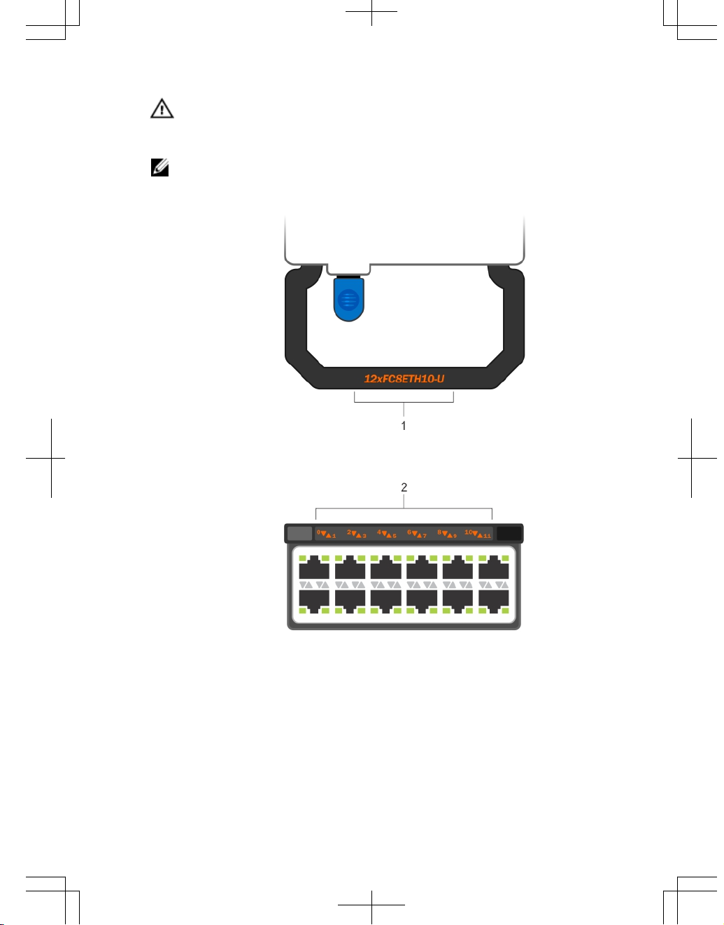
NOTE: For the Ethernet module, the part name and port number are inscribed on the
handle, as shown in the following figure:
18
NOTE: A blue color release latch indicates that the Ethernet module does not
support hot swapping during switch operations. Instead, you must power down the
switch before removing and replacing an Ethernet module. A red color release
latch indicates that the Ethernet module supports hot swapping during switch
operations.
Figure 11. Part name and Port number on the Ethernet Module Handle
1. Part Name
2. Port Number
19
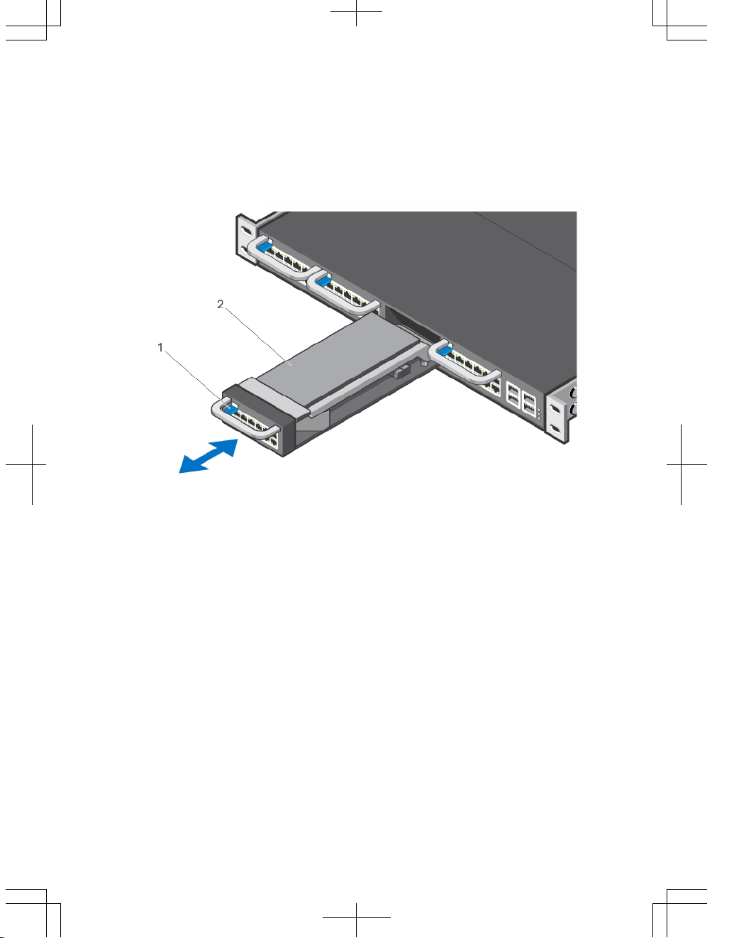
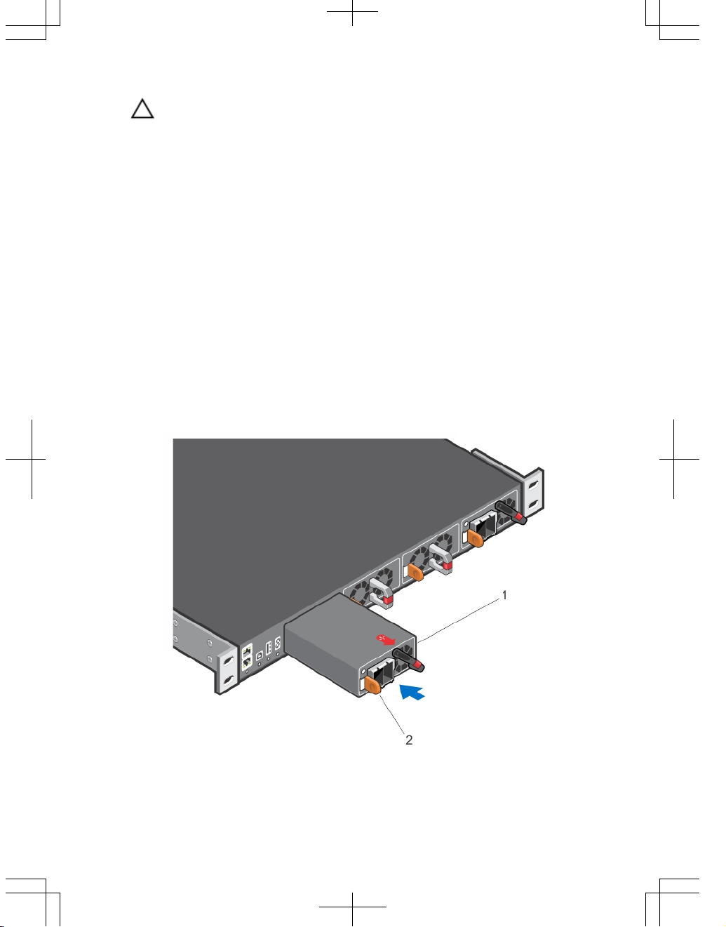
Installing an Ethernet Module
1. Use the grab handle on the Ethernet module to slide it into the switch module slot.
2. Connect any network interface cables to the attached module.
Figure 12. Installing an Ethernet Module
1. Release latch
2. Ethernet Module
Important Points to Remember for Installing a Fibre Channel
Module
• You must insert the Fibre Channel module only in slot 0.
• Installing and swapping of Fibre Channel modules must be done BEFORE power
up. If you need to install or replace a module, power down the system before you
install or replace it. If you install or replace a module when the system is
powered up, the system does not recognize the module. Online insertion of
modules can result in a catastrophic failure.
• The S5000 does not support the hot swapping of a Fibre Channel pluggable
module during switch operations. Instead, you must power down the switch
before removing and replacing a Fibre Channel module.
20
WARNING: Electrostatic discharge (ESD) damage can occur if components are
mishandled. Always wear an ESD-preventive wrist or heel ground strap when
handling the S5000 and its components.
NOTE: The part name and port number of a Fibre Channel module are inscribed on
the handle as shown below.
Figure 13. Part name and Port number on the Fibre Channel Module Handle
1. Part Name
2. Port Number
21
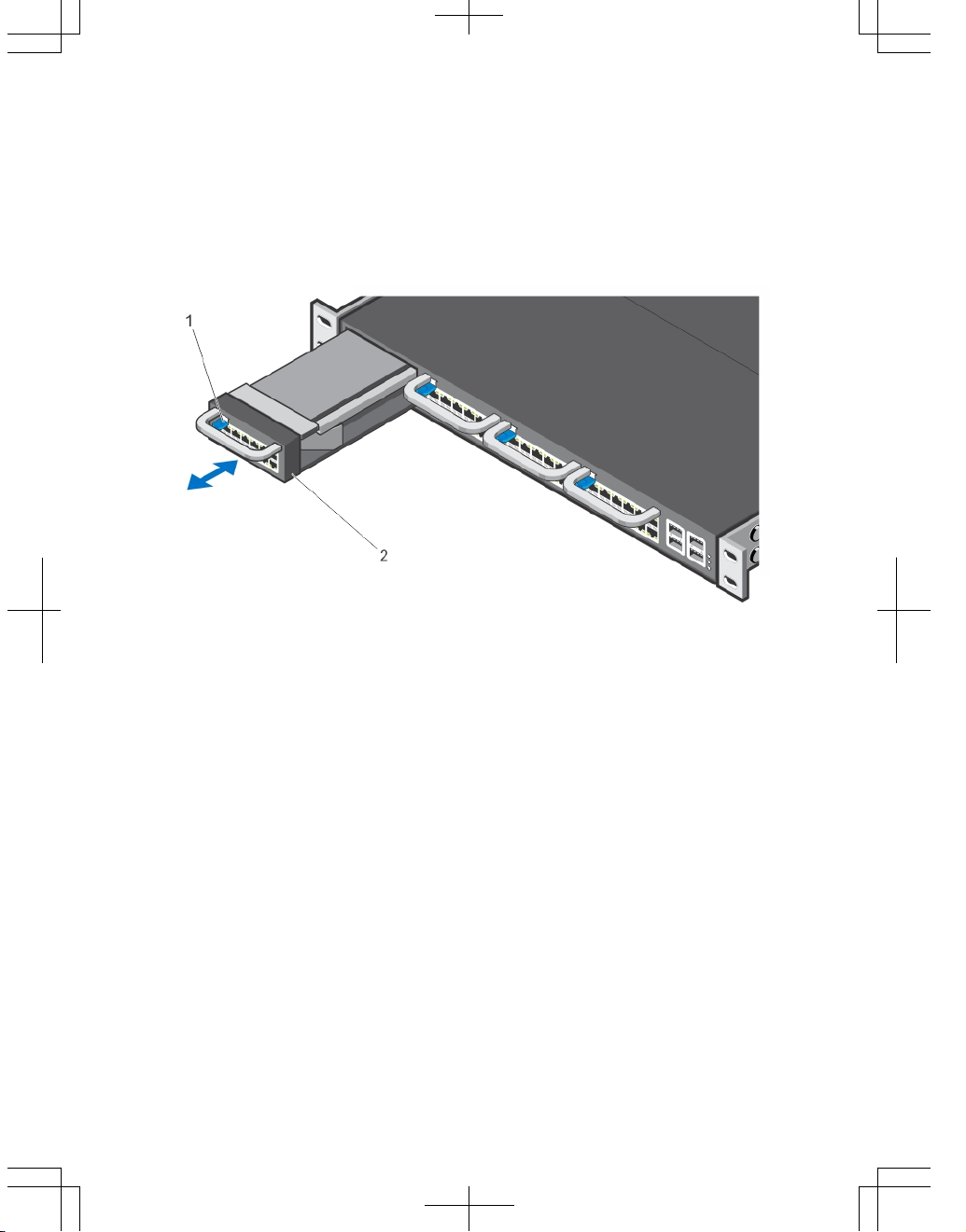
Installing a Fibre Channel Module
1. Use the grab handle on the Fibre Channel module to slide it into the switch module
slot.
2. Connect any network interface cables to the attached module.
Figure 14. Installing a Fibre Channel Module
1. Release latch
2. Fibre Channel Module
Important Points to Remember for Installing an AC Power Supply
• The PSU slides into the slot smoothly. Do not force a PSU into a slot as this
action may damage the PSU or the S5000 chassis.
• The S5000 supports AC and DC power supplies with two air-flow directions (I/O
to Utility and Utility to I/O). The S5000 does not support mixing PSU types, that is,
you cannot replace an AC PSU with a DC PSU and an AC-R PSU with a DC-R
PSU. The fan airflow direction for both the PSUs must be the same.
• For AC PSUs, an illuminated translucent handle indicates the power status.
• To view the log messages, use the show logging command. For more
information, refer to the System Logs chapters of the
FTOS Command Line
22
Reference Guide for the S5000 Switch
and
FTOS Configuration Guide for the
S5000 Switch
.
WARNING: Although the switch can run on one PSU, Dell Networking highly
recommends using two PSUs for full redundancy and proper cooling. If the switch
needs to run with only one PSU for a time, be sure to cover the second PSU slot
opening with a blank plate to avoid overheating.
WARNING: The Utility panel consists of four slots numbered from 0 to 3. Insert
PSUs in slots 0 and 3.
WARNING: The PCB edge connector is at the bottom. Avoid installing the switch
upside down.
WARNING: Electrostatic discharge (ESD) damage can occur if components are
mishandled. Always wear an ESD-preventive wrist or heel ground strap when
handling the S5000 and its components.
CAUTION: DO NOT mix airflow directions. The airflow directions are color coded. A
red label indicates that hot air is expelled from the PSU and a blue label indicates
that hot air is expelled from the I/O. Both power supplies must use the same airflow
direction (I/O to Utility or Utility to I/O). The power supplies and fans must have the
same color strap. If you mismatch the airflows, the following error message
appears and the system shuts down:
00:02:19: %S5000:0 %CHMGR-2-PSU_TYPE_AIRFLOW_MISMATCH:
Mismatching PSU airflow detected. Unit 0 shall get
shutdown in next 60 seconds if mismatch not rectified.
00:02:19: %STKUNIT0-M:CP %CHMGR-1PSU_AIRFLOW_COMBO_MISMATCH: Major alarm: Mismatching
PSU airflow detected in unit 0
Installing an AC Power Supply
1. Remove the PSU from the electro-static bag.
2. Use the grab handle to slide the PSU into the switch PSU slot (install the PSUexposed PCB edge connector first). The PSU slot is keyed so that the PSU can be
fully inserted in only one way. When you install the PSU correctly, it snaps into
place and is flush with the back of the switch.
23
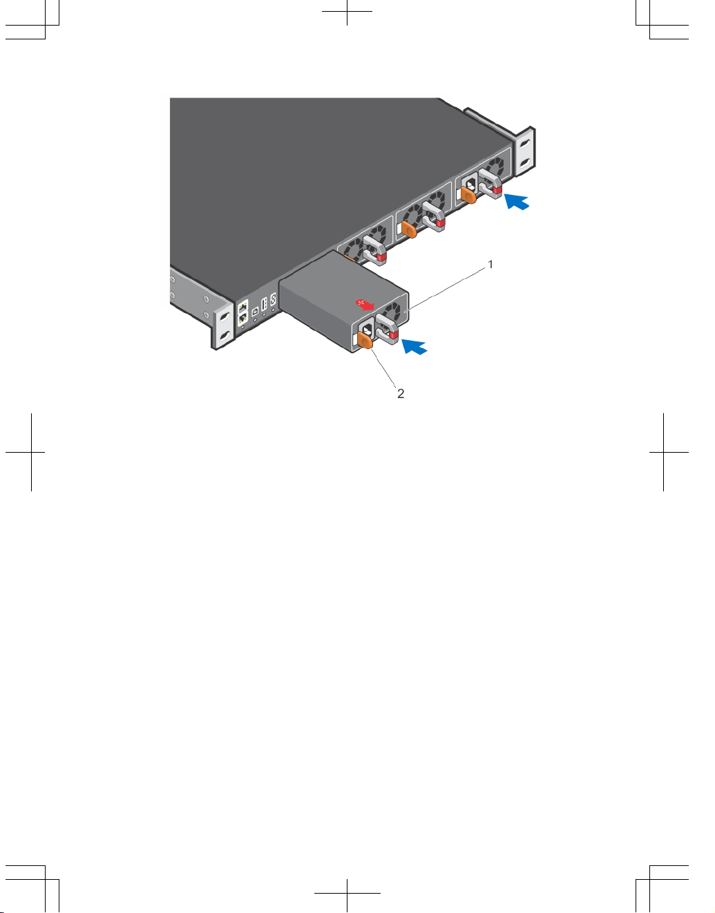
Figure 15. Installing an AC Power Supply
1. Slot 0 (for AC PSU 0)
2. Release latch
3. Plug in the AC3 prong cord from the switch PSU to the external power source (the
AC wall outlet).
24
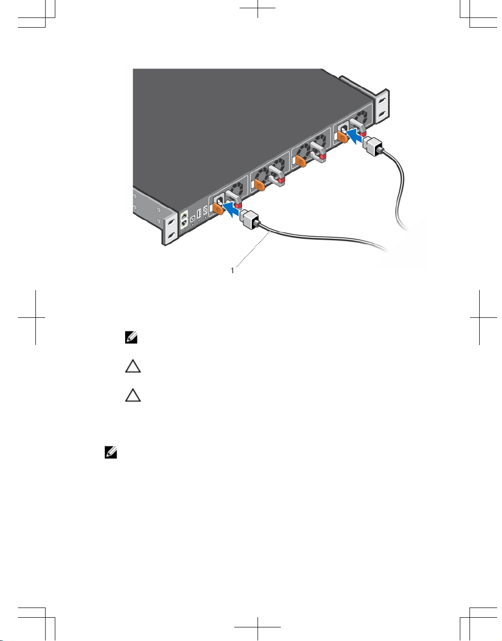
Figure 16. Connecting AC Power Supply Cords
1. AC3 Prong
NOTE: The system is powered-up as soon as you connect the power cord
between the system and the power source.
CAUTION: Always disconnect the power cable before you service the power
supply slots.
CAUTION: Use the power supply cord as the main disconnect device on the
AC system. Ensure that the socket-outlet is located/installed near the
equipment and is easily accessible.
4. Repeat steps 1 through 3 above using the second PSU.
NOTE: Ensure that the PSU is correctly installed. When you correctly install the
PSU, the power connector is on the left side of the PSU.
25
Assembling and Connecting the Safety Ground Wire for DC Power
Supply
WARNING: For equipment using –(48–60) V DC power supplies, a qualified
electrician must perform all connections to DC power and to safety grounds. Do not
attempt connecting to DC power or installing grounds yourself. All electrical wiring
must comply with applicable local or national codes and practices. Damage due to
servicing that Dell Networking did not authorize is not covered by your warranty.
1. Strip the insulation from the end of the green/yellow wire, exposing approximately
4.5 mm (0.175 inch) of copper wire.
2. Using a hand-crimping tool (Tyco Electronics, 58433-3 or equivalent), crimp the ringtongue terminal (Jeeson Terminals Inc., R5-4SA or equivalent) to the green/yellow
wire (safety ground wire).
3. Connect the safety ground wire to the grounding post on the back of the system
using a #6–32 nut equipped with a locking washer.
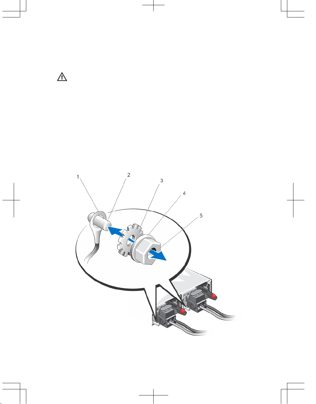
Figure 17. Assembling and Connecting the Safety Ground Wire For DC Power Supply
26
1. Safety ground wire
2. Grounding post
3. Locking washer
4. Spring washer
5. #6–32 nut
Important Points to Remember for Installing a DC Power Supply
• When using DC power supply, peel off the DC electrical label and place it on the
main regulatory label found on the bottom of the S5000 chassis. Position this
label over the AC electrical ratings within the dashed outline.
• The PSU slides into the slot smoothly. Do not force a PSU into a slot as this
action may damage the PSU or the S5000 chassis.
• The S5000 supports AC and DC power supplies with two air-flow directions (I/O
to Utility and Utility to I/O). The S5000 does not support mixing PSU types, that is,
you cannot replace an AC PSU with a DC PSU and an AC-R PSU with a DC-R
PSU. The fan airflow direction for both the PSUs must be the same.
• For DC PSUs, the power status LED is on the upper-left corner.
• A DC PSU must be properly grounded. The system does not work when plugged
into the wrong power source polarity.
• To view the log messages, use the show logging command. For more
information, refer to the System Logs chapters of the
FTOS Command Line
Reference Guide for the S5000 Switch
and
FTOS Configuration Guide for the
S5000 Switch
.
WARNING: Although the switch can run on one PSU, Dell Networking highly
recommends using two PSUs for full redundancy and proper cooling. If the switch
needs to run with only one PSU for a time, be sure to cover the second PSU slot
opening with a blank plate to avoid overheating.
WARNING: The Utility panel consists of four slots numbered from 0 to 3. Insert
PSUs in slots 0 and 3.
WARNING: The PCB edge connector is at the bottom of the switch. Avoid installing
the switch upside down.
WARNING: Electrostatic discharge (ESD) damage can occur if components are
mishandled. Always wear an ESD-preventive wrist or heel ground strap when
handling the S5000 and its components.
27
CAUTION: DO NOT mix airflow directions. The airflow directions are color coded. A
red label indicates that hot air is expelled from the PSU and a blue label indicates
that hot air is expelled from the I/O. Both fans must use the same airflow direction
(I/O to Utility or Utility to I/O). The power supplies and fans must have the same
color strap. If you mismatch the airflows, the following error message appears and
the system shuts down:
00:02:19: %S5000:0 %CHMGR-2-PSU_TYPE_AIRFLOW_MISMATCH:
Mismatching PSU airflow detected. Unit 0 shall get
shutdown in next 60 seconds if mismatch not rectified.
00:02:19: %STKUNIT0-M:CP %CHMGR-1PSU_AIRFLOW_COMBO_MISMATCH: Major alarm: Mismatching
PSU airflow detected in unit 0
Installing a DC Power Supply
1. Remove the PSU from the electro-static bag.
2. Use the grab handle to slide the PSU into the switch PSU slot (install the PSUexposed PCB edge connector first). The PSU slot is keyed so that the PSU can be
fully inserted in only one way. When you correctly install the PSU, it snaps into
place and is flush with the back of the switch.
Figure 18. Installing a DC Power Supply
1. Slot 0 (for DC PSU 0)
28

2. Release latch
3. Strip the insulation from the ends of the DC power wires, exposing approximately 13
mm (0.5 inch) of copper wire.
WARNING: Reversing polarity when connecting DC power wires can
permanently damage the power supply or the system.
4. Insert the copper ends into the mating connectors and tighten the captive screws at
the top of the mating connector using a #2 Phillips screwdriver.
WARNING: To protect the power supply from electrostatic discharge, you
must cover the captive screws with the rubber cap before inserting the mating
connector into the power supply.
5. Rotate the rubber cap clockwise to fix it over the captive screws.
6. Insert the mating connector into the power supply.
Figure 19. Assembling the DC Input Power Wires
1. DC power socket
2. Rubber cap
3. Captive screws (2)
4. DC power connector
5. Wire (-48V)
6. Wire RTN
7. Grounding Wire
29

NOTE: The system is powered-up as soon as the power cord is connected
between the system and the power source.
CAUTION: Always disconnect the power cable before you service the power
supply slots.
CAUTION: Use the power supply cord as the main disconnect device on the
AC or DC system. Ensure that the socket-outlet is located/installed near the
equipment and is easily accessible.
7. Repeat steps 1 through 6 using the second PSU.
NOTE: Ensure that the PSU is correctly installed. When you correctly install the
PSU, the power connector is on the left side of the PSU.
Installing the Ferrite Bead for DC Power and Return Cables
Add a ferrite bead to the DC power and return cables of the master module. Install the
bead with a single loop.
1. Open ferrite bead with the depressions facing up.
2. Wrap the DC power and return cables around the ferrite bead twice if two turns of
the cable fit inside the ferrite, otherwise simply clamp the ferrite onto both cables.
Figure 20. Installing the Ferrite Bead for DC Power and Return Cables
1. Ferrite Bead
2. DC Power and Return Cables
30

3. Leave approximately 4 to 5 inches of the DC power and return cables end protruding
from the ferrite.
4. Snap the ferrite bead shut.
Securing Power Cables
1. Bend the system power cables, as shown in the following illustration, and attach to
the cable clasp.
Figure 21. Securing Power Cables
2. Plug the other end of the power cables into a grounded electrical outlet or a
separate power source such as an uninterruptible power supply (UPS) or a power
distribution unit (PDU).
NOTE: For better performance, ensure that the system is connected to a standalone power source with stable power supply.
Important Points to Remember for Installing a Fan Module
• The Utility panel consists of four slots numbered from 0 to 3. Insert the fan
modules in slots 1 and 2.
• If a fan module fails, the system continues to operate without a significant
degradation in cooling capacity for a six-hour duration.
• The cooling system is designed such that, during normal operation, the fans
typically run at somewhere between 50 and 75 percent of their maximum speed
31

at 26°C ambient temperature. This feature results in lower noise and higher
average fan life. The switch increases the fan speed to maximum if the facility air
condition fails or if a fan fails.
• The fan speed increases and decreases automatically based on the internal
temperature. The switch never intentionally turns off the fans.
• For proper ventilation, position the S5000 in an equipment rack (or cabinet) with a
minimum of 5 inches (12.7 cm) of clearance around the exhaust vents. When you
install two S5000 systems near each other, position the two chassis at least 5
inches (12.7 cm) apart to permit proper airflow. The acceptable ambient
temperature ranges are listed in
Technical Specifications
.
• To view the log messages, use the show logging command. For more
information, refer to the System Logs chapters of the
FTOS Command Line
Reference Guide for the S5000 Switch
and
FTOS Configuration Guide for the
S5000 Switch
.
CAUTION: DO NOT mix airflow directions. The airflow directions are color coded. A
red label indicates that hot air is expelled from the PSU and a blue label indicates
that hot air is expelled from the I/O. Both fans must use the same airflow direction
(I/O to Utility or Utility to I/O). The power supplies and fans must have the same
color strap. If you mismatch the airflows, the following error message appears and
the system shuts down:
00:00:53: %S5000:3 %CHMGR-2-PSU_TYPE_AIRFLOW_MISMATCH:
Mismatching PSU and FAN airflow detected. Unit 0 shall
get shutdown in next 60 seconds if mismatch not
rectified.
00:00:53: %STKUNIT3-M:CP %CHMGR-1PSU_AIRFLOW_COMBO_MISMATCH: Major alarm: Mismatching
PSU and FAN airflow detected in unit 0
The fan modules are field replaceable. Module slot 1 is on the left side of the chassis;
module slot 2 is on the right side of the chassis.
Installing a Fan Module
1. Take the fan module out of the shipping box.
2. Use the grab handle to slide the fan module into the switch fan slot, as shown
below.
32

Figure 22. Installing a Fan Module
1. Fan module 0/Slot 1
2. Release latch
Installing the SFP+ and QSFP+ Optics
The S5000 has 48 small form-factor pluggable plus (SFP+) optical ports and four QSFP+
optical ports.
For a list of supported optics, refer to the S5000 data sheet:
http://www.dell.com/us/
enterprise/p/force10-s-series/pd
.
CAUTION: ESD damage can occur if the components are mishandled. Always wear
an ESD-preventive wrist or heel ground strap when handling the S5000 and its
components.
33

WARNING: When working with optical fibres, follow all the warning labels and
always wear eye protection. Never look directly into the end of a terminated or
unterminated fibre or connector as it may cause eye damage.
1. Position the optic so it is in the correct position. The optic has a key that prevents it
from being inserted incorrectly.
2. Insert the optic into the port until it gently snaps into place.
NOTE: Both rows of QSFP+ ports require that you install the 40GbE optics with the
tabs facing up.
NOTE: When you cable the ports, be sure not to interfere with the airflow from the
small vent holes above and below the ports.
Splitting QSFP+ Ports to SFP+ Ports
The S5000 supports splitting a single 40GbE QSFP+ port into four 10GbE SFP+ ports using
one of the supported breakout cables.
For a list of supported optics, refer to the S5000 data sheet:
http://www.dell.com/us/
enterprise/p/force10-s-series/pd
.
• Configure the system to recognize the port mode change.
CONFIGURATION mode
stack-unit unit-number port number portmode quad
–
stack-unit<unit-number> -
Enter the stack member unit identifier of the
stack member to reset. The range is 0 to 11. The default is 0.
–
port <number>-
Enter the port number of the 40GbE port to be split. The
range is 48 to 60.
–
portmode quad -
Configure a 40GbE port to operate in 4x10GbE mode.
Example of splitting a QSFP+ port to SFP+ ports
stack-unit 0 port 52 portmode quad
Important Points to Remember
• You cannot use split ports as a stack-link to stack an S5000 unit.
• The quad port must be in a default configuration before you can split it into four
10GbE SFP+ ports. When you split the port, the 40GbE port is lost in the running
configuration. Be sure that the port is also removed from other L2/L3 feature
configurations.
• For the split-port change to take effect, you must reload the system after issuing
the CLI change commands.
34

Supplying Power and Powering Up the System
Supply power to the S5000 system after the chassis is mounted in a rack or cabinet.
WARNING: Installing and swapping of Fibre Channel or Ethernet modules must be
done BEFORE power up. If you need to replace a module, power down the system
before you replace it. If you replace a module when the system is powered up, the
system does not recognize the module. Online insertion of modules can result in a
catastrophic failure.
Dell Networking recommends reinspecting your system prior to powering up. Verify that:
• The equipment is properly secured to the rack.
• The equipment rack is properly mounted and grounded.
• The ambient temperature around the unit (which may be higher than the room
temperature) is within the limits specified for the S5000.
• There is sufficient airflow around the chassis.
• The input circuits are correctly sized for the loads and that you use sufficient
overcurrent protection devices.
NOTE: For powering up an AC PSU, an AC power cable is included in the shipping
container. You must order all other power cables separately.
CAUTION: ESD damage can occur if the components are mishandled. Always wear
an ESD-preventive wrist or heel ground strap when handling the S5000 and its
components.
When the system powers up, the fans come on at high speed. The fan speed slows as
the system boots up. The power status LED blinks until the boot-up sequence is
complete. When the boot up is complete, the power status LED is steadily lit.
AC Power
CAUTION: Ensure that the PSU is installed correctly. The AC power connector must
be on the left side of the PSU and the status LED at the top of the PSU.
Connect the plug to each AC power connector. Make sure that the power cord is secure.
As soon as the cable is connected between the S5000 and the power source, the chassis
is powered-up; there is no on/off switch.
DC Power
Connect the plug to each DC receptacle. Make sure that the power cord is secure and
the polarity is correct.
As soon as the cable is connected between the S5000 and the power source, the chassis
is powered-up; there is no on/off switch.
35

Performing the Initial Configuration
The S5000 has two management ports available for system access — a console port and
a universal serial bus (USB)-B port. The USB-B port acts the same as the console port.
The terminal settings are the same for both access ports.
The S5000 supports bare metal provisioning (BMP). For information about how to
configure BMP, refer to
FTOS Configuration Guide for the S5000 Switch
.
Software Configuration Overview
To configure the S5000, follow these steps:
1. Access the RJ-45/RS-232 console port.
2. Enter the initial configuration information.
3. Configure the enable password.
4. Configure a host name.
5. Configure layer 2 (data Link) mode.
6. Configure the management port IP address.
7. Configure a management route.
8. Configure a username and password.
9. Create a port-based VLAN.
10. Assign interfaces to a VLAN.
11. Assign an IP address to a VLAN.
12. Connect the S5000 to the network.
Accessing the RJ-45/RS-232 Console Port
NOTE: Before starting this procedure, be sure that you have a terminal emulation
program already installed on your PC.
The DB9 RS-232/RJ-45 console port is labeled on the lower left-hand side of the S5000 as
you face the Utility side of the chassis.
1. Install an RJ-45 copper cable into the console port. Use a rollover cable to connect
the S5000 console port to a terminal server.
2. Connect the other end of the cable to the DTE terminal server.
3. Set the default terminal settings as follows:
a) 9600 baud rate
36

b) No parity
c) 8 data bits
d) 1 stop bit
e) No flow control
Figure 23. RS-232/RJ-45 Console Port
Accessing the RJ-45 Console Port with a DB-9 Adapter
You can connect to the console using an RJ-45 to RJ-45 rollover cable and an RJ-45 to
DB-9 female DTE adapter to a terminal server (for example, a PC).
The pin assignments between the console and a DTE terminal server are as follows:
Table 6. Pin Assignments Between the Console and a DTE Terminal Server
S5000 Console
Port
RJ-45 to RJ-45
Rollover Cable
RJ-45 to RJ-45
Rollover Cable
RJ-45 to DB-9
Adapter
Terminal Server
Device
Signal RJ-45 Pinout RJ-45 Pinout DB-9 Pin Signal
RTS 1 8 8 CTS
NC 2 7 6 DSR
TxD 3 6 2 RxD
GND 4 5 5 GND
GND 5 4 5 GND
RxD 6 3 3 TxD
NC 7 2 4 DTR
37

S5000 Console
Port
RJ-45 to RJ-45
Rollover Cable
RJ-45 to RJ-45
Rollover Cable
RJ-45 to DB-9
Adapter
Terminal Server
Device
Signal RJ-45 Pinout RJ-45 Pinout DB-9 Pin Signal
CTS 8 1 7 RTS
Accessing the USB-B Console Port
The terminal settings are the same for the USB-B port and the console port:
• 9600 baud rate
• No parity
• 8 data bits
• 1 stop bit
• No flow control
When you connect the USB-B port, it becomes the primary connection and, when the
system is connected, it sends all messages to the USB-B drive.
Figure 24. USB-B Console Port Connector
1. Power on the PC.
2. Install the necessary USB device drivers (you will need an Internet connection). For
assistance, contact Dell Networking Technical Support.
3. Connect the USB-A end of cable into an available USB port on the PC.
4. Connect the USB-B end of cable into the USB-B console port on the S5000.
5. Power on the S5000.
6. Open your terminal software emulation program to access the S5000.
7. Set the terminal connection settings. Use these settings.
38

– 9600 baud rate
– No parity
– 8 data bits
– 1 stop bit
– No flow control
The CLI prompt appears (FTOS>_) when you are connected to the S5000.
NOTE: Only one of the console ports can be active at a time; the USB console takes
priority over the RJ-45 console by default. When a USB Host (PC) is plugged into the
USB console port, the hardware automatically switches over to use the USB
console. When you remove the USB cable or the PC deactivates the USB
connection, the hardware automatically switches to the RJ-45 console interface.
Enter the Initial Configuration Information
To set up the switch, assign an IP address and other configuration information
necessary for the switch to communicate with the local routers and the Internet. The
minimal configuration provided here does not cover most of the features; it simply allows
you to perform other configuration tasks using a Telnet connection from your
management network. To configure other features and interfaces, refer to the
FTOS
Configuration Guide for the S5000 Switch
.
IP Settings
You will need the following information from your network administrator:
• Switch IP address
• Subnet mask (IP netmask)
• Default gateway (router)
• Enable secret password
• Enable password
• Telnet password
Configuring the Enable Password
To access EXEC Privilege mode, use the enable command. EXEC Privilege mode is
unrestricted by default. Configure a password as a basic security measure.
There are two types of enable passwords:
• enable password — stores the password in the running/startup
configuration using a data encryption standard (DES) encryption method.
39

• enable secret — is stored in the running/startup configuration in a
stronger, MD5 encryption method.
NOTE: Dell Networking recommends using the enable secret password.
• Create a password to access EXEC Privilege mode.
CONFIGURATION MODE
enable [password | secret] [level level] [encryptiontype]
level is the privilege level and is not required. The default is 15.
encryption-type: specifies how you are inputting the password and is not
required. The default is
0.
– 0 is for inputting the password in clear text.
– 7 is for inputting a password that is already encrypted using a DES hash.
Obtain the encrypted password from the configuration file of another
Dell Networking system.
– 5 is for inputting a password that is already encrypted using an MD5
hash. Obtain the encrypted password from the configuration file of
another Dell Networking system.
Configuring a Host Name
The host name appears in the prompt. The default host name is FTOS. Host names must
start with a letter, end with a letter or digit, and must have characters, letters, digits, and
hyphens in the string.
• Create a host name.
CONFIGURATION mode
hostname name
40

Navigate CLI modes
The FTOS prompt changes to indicate the CLI mode. You must move linearly through the
command modes, except for the end command which takes you directly to EXEC
Privilege mode and the exit command which moves you up one command mode level.
Default Configuration
A version of FTOS is preloaded onto the S5000; however, the system is not configured
when you power up for the first time (except for the default host name, which is FTOS).
You must configure the system using the CLI.
Configuring Layer 2 (Data Link) Mode
To enable Layer 2 data transmissions through an individual interface, use the
switchport command in INTERFACE mode. You cannot configure switching or Layer
2 protocols, such as spanning tree protocol (STP), on an interface unless the interface
has been set to Layer 2 mode.
1. Enable the interface.
INTERFACE mode
no shutdown
2. Place the interface in Layer 2 (switching) mode
INTERFACE mode
switchport
To view the interfaces in Layer 2 mode, use the show interfaces switchport
command in EXEC mode.
Accessing the System Remotely
You can configure the system to access it remotely by Telnet.
The system has a dedicated management port and a management routing table that is
separate from the IP routing table.
1. Configure an IP address for the management port (refer to
Configuring the
Management Port IP Address
).
2. Configure a management route with a default gateway (refer to
Configuring a
Management Route
).
41

3. Configure a username and password (refer to
Configuring a Username and
Password
).
Configuring the Management Port IP Address
To access the system remotely, assign IP addresses to the management ports.
NOTE: Assign different IP addresses to each stack-unit’s management port.
1. Enter INTERFACE mode for the Management port.
CONFIGURATION mode
interface ManagementEthernet slot/port
– slot range: 0
– port range: 0
2. Assign an IP address to the interface.
INTERFACE mode
ip address ip-address/mask
– ip-address: an address in dotted-decimal format (A.B.C.D).
– mask: a subnet mask in /prefix-length format (/ xx).
3. Enable the interface.
INTERFACE mode
no shutdown
Configuring a Management Route
Define a path from the system to the network from which you are accessing the system
remotely. Management routes are separate from IP routes and are only used to manage
the system through the management port.
• Configure a management route to the network from which you are accessing the
system.
CONFIGURATION mode
management route ip-address/mask gateway
– ip-address: the network address in dotted-decimal format (A.B.C.D).
– mask: a subnet mask in /prefix-length format (/ xx).
– gateway: the next hop for network traffic originating from the
management port.
42

Configuring a Username and Password
• Configure a username and password to access the system remotely.
CONFIGURATION mode
username username password [encryption-type]
encryption-type specifies how you are inputting the password, is 0 by
default, and is not required.
– 0 is for inputting the password in clear text.
– 7 is for inputting a password that is already encrypted using a Type 7
hash. Obtaining the encrypted password from the configuration of
another Dell Networking system.
Creating a Port-based VLAN
The default virtual local area network (VLAN) (VLAN 1) is part of the system startup
configuration and does not require configuration.
To configure a port-based VLAN, create the VLAN and then add physical interfaces or
port channel (LAG) interfaces to the VLAN.
• Configure a port-based VLAN (if the VLAN-ID is different from the Default VLAN
ID) and enter INTERFACE VLAN mode.
CONFIGURATION mode
interface vlan vlan-id
After you create a VLAN, you must assign interfaces in Layer 2 mode to the
VLAN to activate the VLAN.
To view the configured VLANs, use the show vlan command in EXEC Privilege mode.
Assigning Interfaces to a VLAN
You can only assign interfaces in Layer 2 mode to a VLAN using the tagged and
untagged commands. To place an interface in Layer 2 mode, use the switchport
command.
You can designate Layer 2 interfaces as tagged or untagged. When you place an
interface in Layer 2 mode using the switchport command, the interface is
automatically designated untagged and placed in the Default VLAN.
To view which interfaces are tagged or untagged and to view which VLAN the interfaces
belong, use the show vlan command.
43

To view just the interfaces that are in Layer 2 mode, use the show interfaces
switchport command in EXEC Privilege mode or EXEC mode.
To tag frames leaving an interface in Layer 2 mode, you must assign that interface to a
port-based VLAN to tag it with that VLAN ID.
1. Access the INTERFACE VLAN mode of the VLAN to which you want to assign the
interface.
CONFIGURATION mode
interface vlan vlan-id
2. Enable an interface to include the IEEE 802.1Q tag header.
INTERFACE mode
tagged interface
To move untagged interfaces from the Default VLAN to another VLAN, use the
untagged command.
3. Access the INTERFACE VLAN mode of the VLAN to which you want to assign the
interface.
CONFIGURATION mode
interface vlan vlan-id
4. Configure an interface as untagged. This command is available only in VLAN
interfaces.
INTERFACE mode
untagged interface
Assigning an IP Address to a VLAN
VLANs are a Layer 2 feature. For two physical interfaces on different VLANs to
communicate, you must assign an IP address to the VLANs to route traffic between the
two interfaces. The shutdown command in INTERFACE mode does not affect Layer 2
traffic on the interface.
NOTE: You cannot assign an IP address to the Default VLAN, which, by default, is
VLAN 1. To assign another VLAN ID to the Default VLAN, use the default vlan-id
vlan-id command.
• Configure an IP address and mask on the interface.
INTERFACE mode
ip address ip-address mask [secondary]
44

Connecting the S5000 to the Network
After you have completed the hardware installation and software configuration for the
S5000 system, you can connect to your company network by following your company’s
cabling requirements.
Figure 25. RJ-45 Network/Management Port
Technical Specifications
NOTE: Operate the product at an ambient temperature not higher than 40°C.
CAUTION: Lithium Battery Caution: There is a danger of explosion if the battery is
incorrectly replaced.
NOTE: Replace the battery only with same or equivalent type. Dispose of the
batteries according to the manufacturer's instructions.
Table 7. Chassis Physical Design
Parameter Specifications
Height 1.71 inches (43.5 mm)
Width 17.4 inches (441 mm)
Depth 28 inches (711 mm)
Chassis weight with factory-installed
components
34 pounds (approx.) (15.42 kg)
Rack clearance required
• Front: 5 inches (12.7 cm)
45

Parameter Specifications
• Rear: 5 inches (12.7 cm)
Table 8. Environmental Parameters
Parameter Specifications
Operating temperature 32° to 104°F (0° to 40°C)
Operating humidity 10 to 85 percent (RH), noncondensing
Storage temperature –40° to 158°F (–40° to 70°C)
Storage humidity 5 to 95 percent (RH), noncondensing
Relative humidity 10 to 85 percent, noncondensing
Maximum thermal output 2388 BTU/hr
Maximum Altitude No performance degradation to 6600 ft
Shock Meets Bellcore Zone 4 earthquake
requirements
Table 9. Power Requirements
Parameter Specifications
AC Power supply 100 VAC ~ 240 VAC 50/60 Hz
DC Power supply –48V ~ –60V VDC
Maximum current draw per system
7 A @ 100 VAC
3.5 A @ 200 VAC
Maximum power consumption 700 Watts
46

Dell Networking S5000
Handbuch zum Einstieg

Anmerkungen, Vorsichtshinweise und
Warnungen
ANMERKUNG: Eine ANMERKUNG liefert wichtige Informationen, mit denen Sie den
Computer besser einsetzen können.
VORSICHT: Ein VORSICHTSHINWEIS macht darauf aufmerksam, dass bei Nichtbefolgung
von Anweisungen eine Beschädigung der Hardware oder ein Verlust von Daten droht, und
zeigt auf, wie derartige Probleme vermieden werden können.
WARNUNG: Durch eine WARNUNG werden Sie auf Gefahrenquellen hingewiesen, die
materielle Schäden, Verletzungen oder sogar den Tod von Personen zur Folge haben
können.
© 2013 Dell Inc.
In diesem Text verwendete Marken: Dell™, das Dell Logo, Dell Boomi™, Dell Precision™, OptiPlex™,
Latitude™, PowerEdge™, PowerVault™, PowerConnect™, OpenManage™, EqualLogic™, Compellent,
™
KACE
™
,
FlexAddress
™
,
Force10
™
und
Vostro
™
sind Marken von Dell Inc.
Intel
®
,
Pentium
®
,
Xeon
®
,
Core
®
und
Celeron
®
sind eingetragene Marken der Intel Corporation in den USA und anderen Ländern.
AMD
®
ist
eine eingetragene Marke und AMD Opteron
™
,
AMD Phenom
™
und
AMD Sempron
™
sind Marken von
Advanced Micro Devices, Inc. Microsoft
®
,
Windows
®
,
Windows Server
®
,
Internet Explorer
®
,
MS-DOS
®
,
Windows Vista
®
und
Active Directory
®
sind Marken oder eingetragene Marken der Microsoft Corporation
in den USA und/oder anderen Ländern. Red Hat
®
und
Red Hat
®
Enterprise Linux
®
sind eingetragene
Marken von Red Hat, Inc. in den USA und/oder anderen Ländern. Novell
®
und
SUSE
®
sind eingetragene
Marken von Novell Inc. in den USA und anderen Ländern. Oracle
®
ist eine eingetragene Marke von Oracle
Corporation und/oder ihren Tochterunternehmen. Citrix
®
,
Xen
®
,
XenServer
®
und
XenMotion
®
sind
eingetragene Marken oder Marken von Citrix Systems, Inc. in den USA und/oder anderen Ländern.
VMware
®
,
Virtual SMP
®
,
vMotion
®
,
vCenter
®
und
vSphere
®
sind eingetragene Marken oder Marken von
VMWare, Inc. in den USA oder anderen Ländern. IBM
®
ist eine eingetragene Marke von International
Business Machines Corporation.
2013 - 03
Rev. A00

Handbuch zum Einstieg
Dieses Dokument ist als Handbuch zum Einstieg bestimmt, um neue Systeme in Betrieb
zu setzen, zu betreiben und zu konfigurieren. Vollständige Informationen zur Installation
und Konfiguration finden Sie in den unten aufgeführten Informationen:
Tabelle 10. S5000-Dokumente
Informationen Dokumentation
Anleitungen zur Hardware-Installation und
Inbetriebnahme
Installieren des S5000-Switch
Softwarekonfiguration
FTOS-Konfigurationshandbuch für den
S5000-Switch
Befehlszeilenschnittstelle
FTOS Command Line Reference Guide
(FTOS-Befehlszeilenreferenzhandbuch) für
den S5000-Switch
Neueste Aktualisierungen
FTOS-Versionshinweise für den S5000Switch
Einführung
Dieses Dokument enthält grundlegende Informationen zum S5000-Switch sowie
Anweisungen zum Installieren des Switch und zur Erstkonfiguration.
Weitere Informationen zur Konfiguration und zu Switch-Funktionen finden Sie im
FTOS
Configuration Guide for the S5000 Switch
(Konfigurationshandbuch für den S5000-
Switch), das Sie auf der Dell Supportwebsite unter
http://www.dell.com/support/manuals
herunterladen können.
Produktbeschreibung
Der S5000 gehört zu den Switches der Dell Networking S-Series für Data Center Top of
Rack (ToR)-Switches.
Der S5000 wurde speziell dafür entwickelt, Flexibilität in IT-Infrastrukturen und
virtualisierten Umgebungen zu gewährleisten. Es handelt sich um eine 10G ToR-Lösung,
die konvergierte lokale Netzwerke (LAN, Local Area Network) und
Speicherbereichsnetzwerke (SAN, Storage Area Network) im gleichen Gehäuse
ermöglicht. Der S5000 stellt Fibre Channel over Ethernet (FCoE)- und Fibre Channel (FC)Leistung in einer ToR-Switch-Variante mit einer Höheneinheit bereit.
3

Der S5000 unterstützt Data Center Bridging (ETS/PFC/DCBX), FCoE Transit (FIP
Snooping), NPIV Proxy Gateway (NPG), und iSCSI-Speicherdatenverkehr (iSCSI, Internet
Small Computer System Interface). Darüber hinaus bietet der S5000 Funktionen für
Aggregation und Konvergenz durch Steckmodule für die flexible Konfiguration.
Auspacken des Switch
Der S5000 und das Zubehör werden in mehreren Einzellieferungen versandt. Überprüfen
Sie die Verpackung, bevor Sie den Switch auspacken, und melden Sie umgehend alle
Anzeichen von Schäden. Überprüfen Sie, ob Sie alle bestellten Artikel erhalten haben.
Wenn Sie einen Switch S5000 bestellen, sind zum Beispiel die folgenden Artikel
enthalten.
WARNUNG: Sollte ein Artikel fehlen oder beschädigt sein, wenden Sie sich an
Ihren Dell Networking Vertreter oder Vertriebspartner.
WARNUNG: Wenn die Komponenten falsch gehandhabt werden, können Schäden
durch elektrostatische Entladung (ESD) entstehen. Tragen Sie zur ESD-Vorbeugung
immer ein Armband oder Absatzriemen zur Erdung beim Umgang mit dem S5000
und den dazugehörigen Komponenten.
• Ein Switch S5000
• Zwei Lüfter
• Zwei Netzteile (entweder Wechselstrom oder Gleichstrom)
• Ein Schienen-Kit (Kreuzschlitzschraubenzieher der Größe 1 und 2 erforderlich)
• Schrauben für das Installieren des Racks
• Zwei bis vier E/A-Module (entsprechend der Reihenfolge)
• Zwei Blindplatten
• Ein Kabel vom Typ RJ-45-an-DB-9 (Buchse)
• Zwei Gleichstrom- oder Wechselstromkabel für Gleichstrom- oder
Wechselstromeinheiten (länder-/regionsspezifisch)
•
Handbuch zum Einstieg
•
Sicherheits- und Betriebsbestimmungen
•
Garantie- und Supportinformationen
•
Softwarelizenzvereinbarung
1. Stellen Sie das Paket auf eine saubere, ebene Fläche und durchtrennen Sie alle
Befestigungsbänder.
2. Öffnen Sie die Verpackung oder entfernen Sie die obere Abdeckung.
3. Nehmen Sie alle Komponenten vorsichtig aus der Verpackung und stellen Sie sie
auf eine stabile, saubere Fläche.
4

4. Entfernen Sie das gesamte Verpackungsmaterial.
5. Untersuchen Sie den Switch und das Zubehör auf Schäden.
Wichtige Informationen bevor Sie fortfahren
• Machen Sie sich mit dem E/A- und dem Einschubbereich am Gehäuse vertraut.
Der E/A-Bereich hat vier Ports mit 40 GbE auf der rechten Seite des Bereichs,
siehe Abbildung 1. Der Einschubbereich hat die vier festen Steckplätze für die
Stromversorgung, Leuchtdioden und USB-Steckplätze auf der linken Seite des
Bereichs, siehe Abbildung 3.
• Machen Sie die Steckplätze 0, 1, 2 und 3 im E/A-Bereich ausfindig, siehe
Abbildung 2. Sie können in Steckplatz 0 ein Fibre Channel-Modul einfügen. Sie
können die Ethernet-Module in Steckplatz 0, 1, 2 und 3 installieren.
• Machen Sie die Steckplätze 0, 1, 2 und 3 im Einschubbereich ausfindig, siehe
Abbildung 3. Netzteile können nur in Steckplätze 0 und 3 eingesetzt werden. Die
Lüftermodule können in einen beliebigen Steckplatz eingesetzt werden.
Abbildung 1. S5000 E/A- und Einschubbereiche
1. E/A-Platine
2. Einschubbereich
3. Vier 40 GbE QSFP+-Ports (jeder Port unterstützt AUSSERDEM den 4 × 10
GbE-Modus)
5

Übersicht über die Hardware-Installation
Führen Sie zur Installation des S5000 die folgenden Schritte aus:
1. Bringen Sie die Montagehalterungen an.
2. Installieren Sie das S5000-Gehäuse in einem 4-Pfosten-Rack oder -Gehäuse.
3. Erden Sie das Rack.
4. Installieren Sie die Ethernet- und/oder Fibre Channel-Module (ein Fibre ChannelModul darf nur in Steckplatz 0 installiert werden).
5. Installieren Sie die Netzteile.
6. Sichern Sie die Stromversorgungskabel.
7. Installieren Sie die Lüftermodule.
8. Installieren Sie die SFP+- und QSFP+-LWL-Module.
9. Verbinden Sie das Gerät mit der Stromversorgung und fahren Sie das System hoch.
Hardware-Übersicht
Dieser Abschnitt enthält Informationen über Geräteeigenschaften und modulare
Hardwarekonfigurationen für den S5000.
Der S5000 weist die folgenden Abmessungen auf:
• Höhe: 1,71 Zoll (4,4 cm)
• Breite: 17,4 Zoll (44,2 cm)
• Tiefe: 28 Zoll (71,1 cm)
Der Gehäuseaufbau des S5000 ist für Switchbandbreiten von 640 Gbps ausgelegt.
Das System bietet auch einen DB9 RS-232-Konsolen-Port mit YOST RJ-45-Pinbelegung
und einem dedizierten Ethernet-Serviceanschluss für Out-of-Band (OOB)Managementfunktionen.
E/A-Leiste
Alle festen Daten-Ports (4 x 40 GbE-Quad Small Form-Factor Pluggable Plus [QSFP+]Ports) und die vier Steckplätze für einsteckbare Module befinden sich im E/A-Bereich.
Der E/A-Bereich beinhaltet:
• Einsteckbare Module
– 12-Port-Ethernet-Module (1 G/10 G Datendurchsatz)
6

– 12-Port-Fibre Channel-Module (2 G/4 G/8G Datendurchsatz)
• 4 × 40 GbE QSFP+-Ports und LEDs
Abbildung 2. E/A-Bereich des S5000
1. Steckplatz 0 (unterstützt Ethernetund Fibre Channel-Module)
2. Steckplatz 1 (unterstützt nur
Ethernet-Module)
3. Steckplatz 2 (unterstützt nur
Ethernet-Module)
4. Steckplatz 3 (unterstützt nur
Ethernet-Module)
5. Vier 40 GbE QSFP+-Ports (jeder Port
unterstützt AUSSERDEM den 4 × 10
GbE-Modus)
ANMERKUNG: Die LED-Anzeigen für den Systemstatus befinden sich auf beiden
Seiten des Gehäuses. Die Lüfter- und Energiestatus-LEDs befinden sich auf im
Einschubbereich.
Einschubbereich
Die Seite des Einschubbereichs der Plattform enthält die Lüfter- und
Stromversorgungsmodule.
Abbildung 3. Stromversorgungen und Lüftermodule des S5000
7

1. Steckplatz 0 (für
Stromversorgungseinheit 0)
2. Steckplatz 1 (für Lüftermodul 0)
3. Steckplatz 2 (für Lüftermodul 1)
4. Steckplatz 3 (für
Stromversorgungseinheit 1)
5. Griffe
Netzteile
Der S5000 unterstützt zwei bei laufendem Betrieb austauschbare
Stromversorgungseinheiten.
ANMERKUNG: Die Stromversorgungseinheit muss vor Ort installiert werden.
Der S5000 hat SKU, die die folgenden Konfigurationen unterstützen:
• Wechselstrom-Netzteil mit Luftstrom vom E/A- zum Einschubbereich
• Wechselstrom-Netzteil mit Luftstrom vom Einschub- zum E/A-Bereich
• Gleichstrom-Netzteil mit Luftstrom vom E/A- zum Einschubbereich
• Gleichstrom-R-Netzteil mit Luftstrom vom Einschub- zum E/A-Bereich
Netzteile sind vor Ort austauschbar. Um die Energieredundanz und eine angemessene
Kühlung sicherzustellen, installieren Sie zwei Stromversorgungen in den Switch. Bei
Betrieb mit voller Redundanz (zwei Netzteile installiert und in Betrieb) können Sie ein
Netzteil entfernen und ersetzen, während das andere Netzteil ohne Unterbrechung des
Datenverkehrs betrieben wird.
Lüfter
Der S5000 unterstützt zwei Lüftereinsätze mit Luftstromrichtungen vom E/A- zum
Einschubbereich oder vom Einschub- zum E/A-Bereich.
Vermischen Sie nicht die Luftströme vom E/A- zum Einschubbereich und vom Einschubzum E/A-Bereich in einem S5000-Gehäuse. Alle Lüfter und Netzteile derselben
Konfiguration müssen sich in derselben Luftstromrichtung befinden. Wenn Sie eine
Konfiguration mit gemischtem Luftstrom erstellen, macht Sie die Software auf die
unzulässige Konfiguration aufmerksam.
Die Lüfter müssen am Kundenstandort installiert werden.
8

Konventionen für die Portnummerierung
Geradzahlig nummerierte Ports befinden sich am unteren Rand der E/A-Platine und für
Module ungeradzahlige Ports befinden sich am oberen Rand der E/A-Platine.
Abbildung 4. Portnummerierung
Die vorherige Abbildung zeigt die vier festen 40GbE-Datenports (Ports 48, 52, 56, und 60)
und die vier Steckplätze für einsteckbare Module im E/A-Bereich des S5000. Sie können
auch die 40GbE-Ports im 4 × 10GbE-Modus verwenden.
Der S5000 unterstützt die folgenden Module:
• 12-Port-Ethernet-Modul (1G/10G Datendurchsatz) (Steckplatz 0, 1, 2, oder 3)
• 12-Port-Fibre Channel-Modul (2G/4G/8G Datendurchsatz) (Steckplatz 0)
Die zulässigen Steckplatznummern sind Stack-Einheit-Nummern (von 0 bis 11). Die
gültigen Portnummern für jede Schnittstelle sind:
• 1GbE: Ports 0 bis 47
• 10GbE: Ports 0 bis 63
• 40GbE: Ports 48, 52, 56, und 60
• Fibre Channel: Ports 0 bis 11
• Verwaltung: Port 0
Systemstatus
Sie können Statusinformationen des S5000 auf verschiedene Arten ablesen; dazu
gehören die Leuchtdioden und die CLI-Befehle vom Typ show sowie die Anwendung
eines einfachen Netzwerk-Verwaltungsprotokolls (SNMP).
Weitere Informationen zu diesen Optionen finden Sie im
FTOS Command Line Reference
Guide
(FTOS-Befehlszeilen-Referenzhandbuch) und im
FTOS Configuration Guide for the
S5000 Switch
(FTOS-Konfigurationshandbuch für den S5000-Switch).
9

Wie in der folgenden Abbildung gezeigt, weist der S5000 LEDs an der E/A- und
Einschubseite des Gehäuses auf. Wenn der S5000 hochfährt oder eingeschaltet wird,
leuchtet die Status-LED an den Stromversorgungen ununterbrochen grün auf.
Die folgende Tabelle enthält eine Liste der LED-Definitionen für das S5000-System.
Abbildung 5. System-LEDs (Einschubbereich) (Wechselstromversorgungen installiert)
1. Positionssignal-LED
2. Alarm-LED
3. Systemstatus-LED
4. Master-LED
5. Siebensegmentanzeige zum
Identifizieren der Stack-IDs
6. Status-LED der
Stromversorgungseinheit
7. Lüfterstatus-LED
ANMERKUNG: Für Wechselstromversorgungseinheiten zeigt ein beleuchteter,
transparenter Griff den Energiestatus an.
ANMERKUNG: Bei Gleichstromnetzteilen befindet sich die LED, die den
Energiestatus anzeigt, in der oberen linken Ecke.
Abbildung 6. System-LEDs (E/A-Bereich)
10

1. Positionssignal-LED
2. Alarm-LED
3. Systemstatus-LED
Tabelle 11. System-LEDs (Einschub- und E/A-Bereich)
Label LED-Farbe/-Anzeige Beschreibung
Positionssignal-LED
• Aus
• Blau
• Keine Aktivität
• Systemblinklicht/positionsgeber
Alarm-LED
• Aus
• Durchgängig gelb
• Durchgängig rot
• Kein Alarm
• Nicht kritischer
Alarm
• Kritischer Alarm
Systemstatus-LED
• Aus
• Durchgängig grün
• Grün, blinkend
• Durchgängig gelb
• Keine
Stromversorgung
• Normaler Betrieb
• System fährt hoch
• Problem mit
Systemplatine
Master-LED
• Durchgängig grün
• Grün, blinkend
• Aus
• Switch im Stacking
Master- ODER
Switch im
Standalone-Modus
• Switch im Stacking
Standby-Modus
• Switch im Stacking
Member-Modus
Status-LED der
Stromversorgungseinheit
• Durchgängig grün
• Aus
• Normaler Betrieb
• Strom nicht
vorhanden
Lüfterstatus-LED
• Durchgängig grün
• Aus
• Normaler Betrieb
• Strom nicht
vorhanden
11

Abbildung 7. Modul-LEDs
1. Port-Positionssignal-LED
2. Portlink/Vorgangs-LED
3. Modul-Positionssignal-LED
4. Modulstatus-LED
ANMERKUNG: Die nach unten und nach oben zeigenden Dreiecke zeigen jeweils
die unteren und oberen LEDs an.
Tabelle 12. Ethernet-Port/Modul-LEDs
Label LED-Farbe/-Anzeige Beschreibung
Port-Positionssignal-LED
• Aus
• Blau
• Keine Aktivität
• Portblinklicht/Positionsgeber
Portlink/Vorgangs-LED
• Aus
• Durchgängig grün
• Grün, blinkend
• Kein Link oder
Schnittstelle
deaktiviert
• Link vorhanden und
Schnittstelle
aktiviert (EthernetModul)
• Port ist aktiv
12

Label LED-Farbe/-Anzeige Beschreibung
Modul-Positionssignal-LED
• Aus
• Blau
• Keine Aktivität
• Modulblinklicht/Positionsgeber
Modulstatus-LED
• Aus
• Durchgängig grün
• Gelb
• Modul ist nicht
hochgefahren
• Modul ist
hochgefahren
• Problem mit Modul
erkannt
Tabelle 13. Fibre Channel Port/Modul-LEDs
Label LED-Farbe/-Anzeige Beschreibung
Port-Positionssignal-LED
• Aus
• Blau
• Grün
• Keine Aktivität
• Portblinklicht/Positionsgeber
• Fibre ChannelModus aktiviert
Portlink/Vorgangs-LED
• Aus
• Durchgängig grün
• Grün, blinkend
• Kein Link oder
Schnittstelle
deaktiviert
• Link vorhanden und
Schnittstelle
aktiviert
• Port ist aktiv
Modul-Positionssignal-LED
• Aus
• Grün
• Keine Aktivität
• Modulblinklicht/Positionsgeber
Modulstatus-LED
• Aus
• Durchgängig grün
• Gelb
• Modul ist nicht
hochgefahren
• Modul ist
hochgefahren
• Problem mit Modul
erkannt
13

Abbildung 8. LEDs für QSFP+-Port
1. Portlink/Vorgangs-LED
Tabelle 14. 40 GbE-Port/Modul-LEDs
Label LED-Farbe/-Anzeige Beschreibung
Portlink/Vorgangs-LED
• Aus
• Durchgängig grün
• Grün, blinkend
• Kein Link oder
Schnittstelle
deaktiviert
• Link vorhanden und
Schnittstelle
aktiviert
• Port ist aktiv
Installation
Überprüfen Sie vor der Installation des Switch die Einhaltung der folgenden Richtlinien:
• Ausreichend Freiraum vor dem Switch, sodass Sie die Leuchtdioden ablesen
können.
• Wechsel-/Gleichstromkabel reicht von der Steckdose bis zum Stecker des
Einschubbereichs.
• Der Switch muss zuerst im Rack montiert werden, bevor Sie die Netzteilmodule
installieren.
• Die Verkabelung befindet sich in ausreichender Entfernung von elektrischen
Interferenzen, wie Radios, Stromkabel und Leuchtstoffröhren. Stellen Sie sicher,
dass sich die Verkabelung in sicherer Entfernung zu anderen Geräten befindet,
die die Kabel beschädigen könnten. Falls nötig, lassen Sie eine Höheneinheit
zwischen einzelnen Geräten frei, um Raum für die Verkabelung zu schaffen.
14

• Der Luftstrom um den Switch herum und durch die Lüftungen ist ungehindert.
• Die Temperatur um die Einheit liegt bei höchstens 104 °F (40 °C). Wenn sich der
Switch in einer geschlossenen oder Multirack-Konfiguration befindet, ist die
Temperatur möglicherweise höher als die normale Raumtemperatur.
• Die Luftfeuchtigkeit im Bereich des Switch liegt bei höchstens 85 Prozent.
• Der Installationsstandort befindet sich auf einer Höhe von höchstens 6600 Fuß
(2011,7 m).
• Der Switch sollte in einer Umgebung installiert werden, die möglichst frei von
Staub und leitfähigem Fremdmaterial (z. B. Metallspäne aus
Konstruktionsprozessen) ist. Kühlungsmechanismen, z. B. Lüfter und Gebläse im
Switch, können Staub und andere Partikel ansaugen, die zu einer Anhäufung von
Verschmutzungen führen kann, was wiederum eine Fehlfunktion des Systems
bedingen kann.
Installieren des S5000-Gehäuses in einem Rack oder Schrank
Für die Installation des S5000-Systems empfiehlt Dell Networking das Ausführen
der Installationsvorgänge in der hier dargestellten Reihenfolge.
ANMERKUNG: Gehen Sie immer vorsichtig mit dem System und seinen
Komponenten um. Vermeiden Sie das Herunterfallen des S5000-Gehäuses oder der
vor Ort austauschbaren Einheiten.
ANMERKUNG: Um für eine optimale Belüftung zu sorgen, platzieren Sie das S5000Gehäuse in einem Rack (oder Schrank) sodass im Bereich der Lüftungsöffnungen
ein Freiraum von mindestens 5 Zoll (12,7 cm) gegeben ist. Die zulässigen
Umgebungstemperaturbereiche sind im Abschnitt
Umweltparameter
aufgeführt.
VORSICHT: Tragen Sie zur ESD-Vorbeugung immer ein Armband oder Absatzriemen
zur Erdung beim Umgang mit dem S5000 und den dazugehörigen Komponenten. Wie
bei allen elektrischen Geräten dieser Art ergreifen Sie alle notwendigen
Vorsichtsmaßnahmen, um Verletzungen bei der Installation des Systems zu
vermeiden. Schaden am ESD können durch eine falsche Handhabung der
Komponenten entstehen.
Anbringen der Montagehalterungen
Der S5000 wird mit zwei Montagehalterungen (Rack-Haltewinkel) und den erforderlichen
Schrauben (acht Schrauben) für eine Rack- oder Gehäuseinstallation geliefert. Die
Halterungen sind dem Paket mit dem Gehäuse beigefügt.
1. Nehmen Sie die Halterungen und Schrauben aus der Verpackung.
2. Schieben Sie die Montagehalterungen wie in der folgenden Abbildung gezeigt ein.
15

Abbildung 9. Schieben Sie die Montagehalterungen ein.
1. Einschubseite des Gehäuses
2. Montagehalterung
3. Halterung (vom Hersteller installiert)
Sicherheitshinweise zur Rack-Montage
Sie können den Switch entweder in das Rack-Fach stellen oder den Switch direkt in ein
19 Zoll breites, EIA-310-E-konformes Rack einschieben.
• Lastverteilung im Rack – Das Überladen bzw. ungleichmäßige Beladen des
Racks kann zu Schäden am Gestell oder Rack führen, was wiederum zu
Störungen an den Geräten oder Verletzungen beim Personal führen kann.
Stabilisieren Sie Racks in einer dauerhaften Position, bevor Sie mit dem Beladen
beginnen. Beginnen Sie mit dem Beladen von unten und arbeiten Sie sich dann
nach oben vor. Überschreiten Sie die Maximallast nicht.
• Hinweise zur Energieversorgung – Verwenden Sie nur die Stromquelle, die an
der Einheit angegeben ist. Wenn mehrere elektrische Komponenten im Rack
montiert sind, stellen Sie sicher, dass die Nennleistung der Komponenten die
Kapazität des Schaltkreises nicht übersteigt. Überlastete Stromquellen und
Verlängerungskabel können das Feuer- und Stromschlagrisiko erhöhen.
• Erhöhte Raumtemperatur – Bei der Installation in einem geschlossenen Rack ist
die Temperatur im Rack selbst höher als die Raumtemperatur. Stellen Sie sicher,
dass die Maximaltemperatur von 40 °C für den Switch nicht überschritten wird.
16

• Eingeschränkter Luftstrom – Installieren Sie das System so im Rack, dass der für
einen ordnungsgemäßen Betrieb erforderliche Luftstrom nicht beeinträchtigt
wird.
• Gegenluftströmung – Es ist ausreichend Freiraum erforderlich, um
sicherzustellen, dass kühle Luft einströmt und heiße Luft nicht aus dem E/ABereich ausströmt.
• Verlässliche Erdung – Die Erdung der Geräte, die auf dem Rack montiert sind,
muss stabil sein. Achten Sie besonders auf die Versorgungsanschlüsse, die
nicht direkt mit dem Endstromkreis verbunden sind, z. B. Mehrfachsteckdosen.
• Montieren Sie das System so, dass der Einschubbereich nach unten zeigt.
WARNUNG: Diese Anweisungen sind nur eine Zusammenfassung. Lesen Sie die
Anweisungen in der Broschüre „Sicherheits-, Umwelt- und
Zulassungsbestimmungen“, bevor Sie mit der Montage beginnen.
ANMERKUNG: Die Abbildungen in diesem Dokument gelten nicht für einen
spezifischen Switch.
Installieren des S5000-Gehäuses in einem 4-Pfosten-Rack oder Gehäuse
ANMERKUNG: Dell Networking empfiehlt, dass eine Person das S5000-Gehäuse in
Position hält, während eine zweite Person die Haltebügel an den Pfosten befestigt.
Befestigen Sie die Haltebügel mit zwei Schrauben je Bügel am Rack oder
Gehäusepfosten. Stellen Sie sicher, dass die Schrauben fest angezogen sind.
17

Abbildung 10. Installation des vorderen Racks
1. Schrauben
2. 4–Pfosten-Rack oder -Gehäuse
3. Montagehalterung
Rack-Erdung
Wenn Sie das Geräte-Rack vorbereiten, stellen Sie sicher, dass das Rack geerdet ist.
Das Geräte-Rack muss an dem Erdungspunkt geerdet sein, der auch für die
Stromversorgung in diesem Bereich verwendet wird. Die Erdungsleitung muss
permanent sein.
Wichtige Informationen für die Installation eines Ethernet-Moduls
• Installieren oder ersetzen Sie Ethernet-Module VOR dem Einschalten. Wenn Sie
ein Modul installieren oder ersetzen müssen, schalten Sie das System vor dem
Ersetzen oder der Installation aus. Wenn Sie ein Modul ersetzen oder
installieren, während das System eingeschaltet ist, erkennt das System dieses
Modul nicht. Das Ersetzen von Modulen bei eingeschaltetem System kann
schwerer Störungen zur Folge haben.
18

WARNUNG: Wenn die Komponenten falsch gehandhabt werden, können Schäden
durch elektrostatische Entladung (ESD) entstehen. Tragen Sie zur ESD-Vorbeugung
immer ein Armband oder Absatzriemen zur Erdung beim Umgang mit dem S5000
und den dazugehörigen Komponenten.
ANMERKUNG: Der Teilename und die Portnummer sind auf dem Griff des EthernetModuls vermerkt, siehe folgende Abbildung:
19

ANMERKUNG: Eine blaue Freigabevorrichtung zeigt an, dass das Ethernet-Modul
einen Austausch bei laufendem Switch-Betrieb nicht unterstützt. Bei einem
Austausch muss der Switch heruntergefahren werden, bevor das Ethernet-Modul
entfernt und ersetzt werden kann. Eine rote Freigabevorrichtung zeigt an, dass das
Ethernet-Modul bei laufendem Switch-Betrieb ausgetauscht werden kann.
Abbildung 11. Teilename und Portnummer auf dem Griff des Ethernet-Moduls
1. Teilename
2. Schnittstellennummer
20

Installieren eines Ethernet-Moduls
1. Verwenden Sie den Haltegriff am Ethernet-Modul, um es in den Modulsteckplatz
des Switch einzuschieben.
2. Verbinden Sie alle Netzwerkschnittstellenkabel mit dem eingeschobenen Modul.
Abbildung 12. Installieren eines Ethernet-Moduls
1. Freigabevorrichtung
2. Ethernet-Modul
Wichtige Informationen für die Installation eines Fibre ChannelModuls
• Das Fibre Channel-Modul darf nur in Steckplatz 0 eingesteckt werden.
• Das Installieren oder Ersetzen von Fibre Channel- oder Ethernet-Modulen muss
VOR dem Einschalten erfolgen. Wenn Sie ein Modul installieren oder ersetzen
müssen, schalten Sie das System vor dem Ersetzen oder der Installation aus.
Wenn Sie ein Modul ersetzen oder installieren, während das System
eingeschaltet ist, erkennt das System dieses Modul nicht. Das Ersetzen von
Modulen bei eingeschaltetem System kann schwere Störungen zur Folge haben.
21

• Der S5000 unterstützt den Austausch eines einsteckbaren Fibre Channel-Moduls
bei laufendem Switch-Betrieb nicht. Der Switch muss vor dem Entfernen und
Ersetzen eines Fibre Channel-Moduls heruntergefahren werden.
WARNUNG: Wenn die Komponenten falsch gehandhabt werden, können Schäden
durch elektrostatische Entladung (ESD) entstehen. Tragen Sie zur ESD-Vorbeugung
immer ein Armband oder Absatzriemen zur Erdung beim Umgang mit dem S5000
und den dazugehörigen Komponenten.
22

ANMERKUNG: Der Teilename und die Portnummer eines Fibre Channel-Moduls
sind wie unten beschrieben auf dem Griff vermerkt.
Abbildung 13. Teilename und Portnummer auf dem Griff des Fibre Channel-Moduls
1. Teilename
2. Schnittstellennummer
Installieren eines Fibre Channel-Moduls
1. Verwenden Sie den Haltegriff am Fibre Channel-Modul, um es in den Einschub des
Switch-Moduls einzuschieben.
2. Verbinden Sie alle Netzwerkschnittstellenkabel mit dem eingeschobenen Modul.
23

Abbildung 14. Installieren eines Fibre Channel-Moduls
1. Freigabevorrichtung
2. Fibre Channel-Modul
Wichtige Informationen für das Installieren eines
Wechselstromnetzteils
• Das Netzteil gleitet sanft in den Steckplatz. Führen Sie ein Netzteil nicht mit
Gewalt in einen Steckplatz ein, da dies das Netzteil oder das S5000-Gehäuse
beschädigen kann.
• Der S5000 kann mit Wechselstrom-/Gleichstromnetzteilen mit zwei
Luftstomrichtungen (E/A- zu Einschubbereich und Einschub- zu E/A-Bereich)
betrieben werden. Der S5000 unterstützt keine Mischtypen von Netzteilen, d. h.
Sie können kein Wechselstromnetzteil durch ein Gleichstromnetzteil, und kein
Wechselstrom-R-Netzteil durch ein Gleichstrom-R-Netzteil ersetzen. Die
Luftstromrichtung des Lüfters muss für beide Netzteile gleich sein.
• Für Wechselstromnetzteile zeigt ein beleuchteter, transparenter Griff den
Energiestatus an.
• Verwenden Sie den Befehl show logging (Protokollierung anzeigen), um die
Protokollmeldungen anzuzeigen. Weitere Informationen finden Sie in den
Kapiteln über Systemprotokolle im
FTOS Command Line Reference Guide for the
S5000 Switch
(FTOS Befehlszeilenreferenzhandbuch für den S5000-Switch) und
im
FTOS Configuration Guide for the S5000 Switch
(FTOS
Konfigurationshandbuch für den S5000-Switch).
24

WARNUNG: Obwohl der Switch mit einem einzigen Netzteil betrieben werden kann,
empfiehlt Dell Networking den Einsatz von zwei Netzteilen, um eine vollständige
Redundanz und ordnungsgemäße Kühlung zu gewährleisten. Wenn der Switch eine
Zeit lang mit nur einem Netzteil betrieben werden muss, bedecken Sie die
Einschuböffnung des zweiten Netzteils mit einer leeren Blindplatte, um eine
Überhitzung zu vermeiden.
WARNUNG: Der Einschubbereich umfasst vier Steckplätze, die von 0 bis 3
nummeriert sind. Setzen Sie die Netzteile in die Steckplätze 0 und 3 ein.
WARNUNG: Der PCB-Platinenstecker ist unten. Vermeiden Sie es, den Switch
umgedreht zu installieren.
WARNUNG: Wenn die Komponenten falsch gehandhabt werden, können Schäden
durch elektrostatische Entladung (ESD) entstehen. Tragen Sie zur ESD-Vorbeugung
immer ein Armband oder Absatzriemen zur Erdung beim Umgang mit dem S5000
und den dazugehörigen Komponenten.
VORSICHT: Mischen Sie die Luftstromrichtung nicht. Die Luftstromrichtungen sind
farblich gekennzeichnet. Eine rote Markierung zeigt an, dass heiße Luft aus dem
Netzteil ausgestoßen wird und eine blaue Markierung zeigt an, dass heiße Luft aus
dem E/A-Bereich ausgestoßen wird. Beide Stromversorgungen müssen die gleiche
Luftstromrichtung verwenden (E/A- zu Einschubbereich oder Einschub- zu E/ABereich). Die Stromversorgungen und die Lüfter müssen die gleiche Farbe haben.
Wenn Sie die Luftstromrichtungen falsch zuordnen, erscheint die folgende
Fehlermeldung und das System schaltet sich ab:
00:02:19: %S5000:0 %CHMGR-2-PSU_TYPE_AIRFLOW_MISMATCH:
Mismatching PSU airflow detected. Unit 0 shall get
shutdown in next 60 seconds if mismatch not rectified.
(Falsch angepasster Luftstrom der Netzteile erkannt.
Einheit 0 wird in den nächsten 60 Sekunden
heruntergefahren, wenn die Fehlanpassung nicht
berichtigt wird.) 00:02:19: %STKUNIT0-M:CP %CHMGR-1PSU_AIRFLOW_COMBO_MISMATCH: Major alarm: Mismatching
PSU airflow detected in unit 0. (Warnung: Falsch
angepasster Luftstrom des Netzteils in Einheit 0
erkannt.)
Installieren eines Wechselstrom-Netzteils
1. Nehmen Sie das Netzteil aus der elektrostatischen Tasche.
2. Verwenden Sie den Haltegriff, um das Netzteil in den Steckplatz der SwitchStromversorgungseinheit einzuschieben (installieren Sie zunächst den PCBPlatinenstecker, der zum Netzteil weist). Der Steckplatz des Netzteils weist
entsprechende Führungsschienen auf, sodass das Netzteil nur in eine Richtung
25

eingeschoben werden kann. Wenn Sie das Netzteil ordnungsgemäß installieren,
rastet es ein und ist bündig mit der Rückseite des Switch.
Abbildung 15. Installieren eines Wechselstrom-Netzteils
1. Steckplatz 0 (für Wechselstrom-Netzteil 0)
2. Freigabevorrichtung
3. Verbinden Sie das AC3-Steckerkabel des Switch-Netzteils mit der externen
Energiequelle (Wechselstrom-Steckdose).
26

Abbildung 16. Verbinden der Wechselstrom-Netzteilkabel
1. AC3-Stecker
ANMERKUNG: Das System wird hochgefahren, sobald Sie das Stromkabel
zwischen System und Energiequelle verbinden.
VORSICHT: Trennen Sie immer das Netzteilkabel, bevor Sie die
Stromversorgungssteckplätze warten.
VORSICHT: Verwenden Sie das Netzteilkabel, um die Stromzufuhr zum Gerät
zu trennen. Stellen Sie sicher, dass sich die Steckdose in der Nähe der Geräte
befindet/installiert ist und einfach zugänglich ist.
4. Wiederholen Sie die oben aufgeführten Schritte 1 bis 3, und verwenden Sie das
zweite Netzteil.
ANMERKUNG: Vergewissern Sie sich, dass das Netzteil ordnungsgemäß installiert
ist. Wenn Sie das Netzteil ordnungsgemäß installieren, befindet sich der
Stromversorgungsanschluss auf der linken Seite des Netzteils.
27

Zusammenbauen und Verbinden des Schutzerdungskabels für das
Gleichstrom-Netzteil
WARNUNG: Bei Geräten, die -(48-60) V-Gleichstrom-Netzteile verwenden, müssen
alle Verbindungen zur Gleichstromversorgung und zur Sicherheitserdung von einem
Elektriker hergestellt werden. Versuchen Sie nicht, die Verbindung zum Gleichstrom
und zur Sicherheitserdung selbst herzustellen. Alle elektrischen Verkabelungen
müssen den zutreffenden lokalen oder nationalen Regeln und Verfahren
entsprechen. Schäden durch nicht von Dell genehmigte Wartungsversuche werden
nicht durch die Garantie abgedeckt.
1. Entfernen Sie die Isolierung an den Enden der grünen/gelben Kupferkabel auf einer
Länge von ca. 0,5 cm.
2. Verwenden Sie eine Handcrimpzange (Tyco Electronics, 58433-3 oder ähnlich) und
crimpen Sie den Ringzungenanschluss (Jeeson Terminals Inc., R5-4SA oder
ähnlich) an das grün/gelbe Kabel (Schutzerdungsleiter).
3. Verbinden Sie das Schutzerdungskabel mit dem Erdungspfosten auf der Rückseite
des Systems und verwenden Sie dabei eine #6–32-Mutter mit Unterlegscheibe.
28

Abbildung 17. Zusammenbauen und Verbinden des Schutzerdungskabels für das
Gleichstrom-Netzteil
1. Schutzerdungsleiter
2. Erdungspfosten
3. Unterlegscheibe
4. Federunterlegscheibe
5. #6–32-Mutter
Wichtige Informationen für das Installieren eines GleichstromNetzteils
• Entfernen Sie bei Verwendung eines Gleichstrom-Netzteils den
Gleichstromaufkleber und bringen Sie ihn auf dem Hauptkontrollaufkleber am
unteren Teil des S5000-Gehäuses an. Bringen Sie diesen Aufkleber über den
elektrischen Angaben für Wechselstrom innerhalb der gestrichelten Außenlinie
an.
• Das Netzteil gleitet sanft in den Steckplatz. Führen Sie ein Netzteil nicht mit
Gewalt in einen Steckplatz ein, da dies die Stromversorgungseinheit oder das
S5000-Gehäuse beschädigen kann.
29

• Der S5000 kann mit Wechselstrom-/Gleichstromnetzteilen mit zwei
Luftstomrichtungen (E/A- zu Einschubbereich und Einschub- zu E/A-Bereich)
betrieben werden. Der S5000 unterstützt keine Mischtypen von Netzteilen, d. h.
Sie können kein Wechselstromnetzteil durch ein Gleichstromnetzteil, und kein
Wechselstrom-R-Netzteil durch ein Gleichstrom-R-Netzteil ersetzen. Die
Luftstromrichtung des Lüfters muss für beide Netzteile gleich sein.
• Bei Gleichstromnetzteilen befindet sich die LED, die den Energiestatus anzeigt, in
der oberen linken Ecke.
• Ein Gleichstromnetzteil muss ordnungsgemäß geerdet sein. Das System
funktioniert nicht, wenn es hinsichtlich der Stromquelle falsch gepolt ist.
• Verwenden Sie den Befehl show logging (Protokollierung anzeigen), um die
Protokollmeldungen anzuzeigen. Weitere Informationen finden Sie in den
Kapiteln über Systemprotokolle im
FTOS Command Line Reference Guide for the
S5000 Switch
(FTOS Befehlszeilenreferenzhandbuch für den S5000-Switch) und
FTOS Configuration Guide for the S5000 Switch
(FTOS Konfigurationshandbuch
für den S5000-Switch).
WARNUNG: Obwohl der Switch mit einem einzigen Netzteil betrieben werden kann,
empfiehlt Dell Networking den Einsatz von zwei Stromversorgungseinheiten, um
eine vollständige Redundanz und ordnungsgemäße Kühlung zu gewährleisten.
Wenn der Switch eine Zeit lang mit nur einem Netzteil betrieben werden muss,
bedecken Sie die Einschuböffnung des zweiten Netzteils mit einer Blindplatte, um
eine Überhitzung zu vermeiden.
WARNUNG: Der Einschubbereich umfasst vier Steckplätze, die von 0 bis 3
nummeriert sind. Setzen Sie die Netzteile in die Steckplätze 0 und 3 ein.
WARNUNG: Der PCB-Platinenstecker befindet sich unten am Switch. Vermeiden
Sie es, den Switch umgedreht zu installieren.
WARNUNG: Wenn die Komponenten falsch gehandhabt werden, können Schäden
durch elektrostatische Entladung (ESD) entstehen. Tragen Sie zur ESD-Vorbeugung
immer ein Armband oder Absatzriemen zur Erdung beim Umgang mit dem S5000
und den dazugehörigen Komponenten.
30

VORSICHT: Mischen Sie die Luftstromrichtungen NICHT. Die Luftstromrichtungen
sind farblich gekennzeichnet. Eine rote Markierung zeigt an, dass heiße Luft aus
dem Netzteil ausgestoßen wird und eine blaue Markierung zeigt an, dass heiße Luft
aus dem E/A-Bereich ausgestoßen wird. Beide Lüfter müssen die gleiche
Luftstromrichtung verwenden (E/A- zu Einschubbereich oder Einschub- zu E/ABereich). Die Stromversorgungen und die Lüfter müssen die gleiche Farbe haben.
Wenn Sie die Luftstromrichtungen falsch zuordnen, erscheint die folgende
Fehlermeldung und das System schaltet sich ab:
00:02:19: %S5000:0 %CHMGR-2-PSU_TYPE_AIRFLOW_MISMATCH:
Mismatching PSU airflow detected. Unit 0 shall get
shutdown in next 60 seconds if mismatch not rectified.
(Falsch angepasster Luftstrom der Netzteile erkannt.
Einheit 0 wird in den nächsten 60 Sekunden
heruntergefahren, wenn die Fehlanpassung nicht
berichtigt wird.) 00:02:19: %STKUNIT0-M:CP %CHMGR-1PSU_AIRFLOW_COMBO_MISMATCH: Major alarm: Mismatching
PSU airflow detected in unit 0. (Warnung: Falsch
angepasster Luftstrom des Netzteils in Einheit 0
erkannt.)
Installieren eines Gleichstrom-Netzteils
1. Nehmen Sie das Netzteil aus der elektrostatischen Tasche.
2. Verwenden Sie den Haltegriff, um das Netzteil in den Steckplatz der SwitchStromversorgungseinheit einzuschieben (installieren Sie zunächst den PCBPlatinenstecker, der zum Netzteil weist). Der Steckplatz des Netzteils weist
entsprechende Führungsschienen auf, sodass das Netzteil nur in eine Richtung
eingeschoben werden kann. Wenn Sie das Netzteil ordnungsgemäß installieren,
rastet es ein und ist bündig mit der Rückseite des Switch.
31

Abbildung 18. Installieren eines Gleichstrom-Netzteils
1. Steckplatz 0 (für Wechselstrom-Netzteil 0)
2. Freigabevorrichtung
3. Entfernen Sie die Isolierung der Kupfer-Gleichstromkabel und legen Sie ca. 13 mm
(0,5 Zoll) frei.
WARNUNG: Durch das Vertauschen der Polung beim Anschluss der
Gleichstromkabel kann das Netzteil oder das System dauerhaft beschädigt
werden.
4. Führen Sie die Kupferenden in die Gegenstecker ein und ziehen Sie die
unverlierbaren Schrauben oben auf dem Gegenstecker mit einem
Kreuzschlitzschraubendreher der Größe 2 an.
WARNUNG: Um das Netzteil vor elektrostatischen Entladungen zu schützen,
müssen Sie die unverlierbaren Schrauben mit Gummiabdeckungen abdecken,
bevor der Gegenstecker in das Netzteil eingesetzt wird.
5. Drehen Sie die Gummiabdeckungen im Uhrzeigersinn, um sie über den
unverlierbaren Schrauben zu befestigen.
6. Fügen Sie den Gegenstecker in das Stromversorgungsmodul ein.
32

Abbildung 19. Eingangs-Gleichstromkabel montieren
1. Gleichstrom-Steckdose
2. Gummiabdeckung
3. Unverlierbare Schrauben (2)
4. GleichstromAnschlussstecker
5. Kabel (-48V)
6. Kabel RTN
7. Erdungskabel
ANMERKUNG: Das System wird hochgefahren, sobald das Stromkabel
zwischen System und Stromquelle verbunden wird.
VORSICHT: Trennen Sie immer das Stromversorgungskabel, bevor Sie die
Stromversorgungssteckplätze warten.
VORSICHT: Verwenden Sie das Stromversorgungskabel als
Stromtrennvorrichtung im Wechsel- oder Gleichstromversorgungssystem.
Stellen Sie sicher, dass sich die Sockelsteckdose nahe der Geräte befindet/
installiert ist und einfach zugänglich ist.
7. Wiederholen Sie die Schritte 1 bis 6, und verwenden Sie das zweite Netzteil.
ANMERKUNG: Vergewissern Sie sich, dass das Netzteil ordnungsgemäß installiert
ist. Wenn Sie das Netzteil ordnungsgemäß installieren, befindet sich der
Stromversorgungsanschluss auf der linken Seite des Netzteils.
33

Installieren des Ferritkerns für Gleichstrom- und
Stromrückleitungskabel
Fügen Sie dem Gleichstrom- und Stromrückleitungskabel des Mastermoduls einen
Ferritkern hinzu. Installieren Sie den Kern mit einer einfachen Wicklung.
1. Öffnen Sie den Ferritkern mit den Vertiefungen nach oben.
2. Wickeln Sie die Gleichstrom- und Stromrückleitungskabel zweimal um den
Ferritkern, wenn zwei Kabelwicklungen in den Ferritkern passen. Andernfalls
klemmen Sie den Ferritkern einfach an beide Kabel.
Abbildung 20. Installieren des Ferritkerns für Gleichstrom- und Stromrückleitungskabel
1. Ferritkern
2. Gleichstrom- und Stromrückleitungskabel
3. Lassen Sie etwa 4 bis 5 Zoll ( 10,2 - 12,7 cm) der Gleichstrom- und
Stromrückleitungskabelenden aus dem Ferritkern herausragen.
4. Lassen Sie den Schnappverschluss des Ferritkerns einrasten.
Befestigen der Stromversorgungskabel
1. Biegen Sie die Systemstromkabel wie in der folgenden Abbildung und befestigen
Sie diese an der Kabelklemme.
34

Abbildung 21. Befestigen der Stromversorgungskabel
2. Verbinden Sie die anderen Enden der Netzstromkabel jeweils mit einer geerdeten
Steckdose oder einer separaten Stromquelle wie z. B. einer unterbrechungsfreien
Stromversorgung (USV) oder einem Stromverteiler (PDU).
ANMERKUNG: Stellen Sie sicher, dass das System an eine eigenständige
Stromquelle mit stabiler Stromversorgung angeschlossen ist, um eine optimale
Leistung zu gewährleisten.
Wichtige Informationen für die Installation eines Lüftermoduls
• Der Einschubbereich besteht aus vier Steckplätzen, die von 0 bis 3 nummeriert
sind. Setzen Sie die Lüftermodule in die Steckplätze 1 und 2 ein.
• Wenn ein Lüftermodul ausfällt, funktioniert das System noch weitere sechs
Stunden ohne bedeutenden Verlust der Kühlleistung.
• Das Kühlsystem ist so ausgelegt, dass die Lüfter bei Normalbetrieb und 26 °C
Umgebungstemperatur normalerweise etwa zwischen 50 und 75 Prozent ihrer
Höchstdrehzahl erreichen. Dadurch werden Betriebsgeräusche verringert und
die durchschnittliche Lebensdauer der Lüfter verlängert. Der Switch steigert die
Lüfterdrehzahl auf die höchste Stufe, wenn die Klimaanlage im Gebäude oder ein
Lüfter ausfällt.
• Die Lüfterdrehzahl wird abhängig von der Innentemperatur automatisch
gesteigert oder verringert. Der Switch schaltet die Lüfter niemals absichtlich
aus.
• Um für eine optimale Belüftung zu sorgen, platzieren Sie den S5000 in einem
Geräte-Rack (oder Gehäuse), sodass im Bereich der Lüftungsöffnungen ein
35

Freiraum von mindestens 5 Zoll (12,7 cm) gegeben ist. Wenn Sie zwei S5000Systeme in geringem Abstand zueinander installieren, platzieren Sie die beiden
Gehäuse in einem Abstand von mindestens 5 Zoll (12,7 cm), um einen
ordnungsgemäßen Luftstrom zu gewährleisten. Die zulässigen
Umgebungstemperaturbereiche sind in
Technische Daten
aufgeführt.
• Verwenden Sie den Befehl show logging (Protokollierung anzeigen), um die
Protokollmeldungen anzuzeigen. Weitere Informationen finden Sie in den
Kapiteln über Systemprotokolle im
FTOS Command Line Reference Guide for the
S5000 Switch
(FTOS Befehlszeilenreferenzhandbuch für den S5000-Switch) und
im
FTOS Configuration Guide for the S5000 Switch
(FTOS
Konfigurationshandbuch für den S5000-Switch).
VORSICHT: Mischen Sie die Luftstromrichtungen NICHT. Die Luftstromrichtungen
sind farblich gekennzeichnet. Eine rote Markierung zeigt an, dass heiße Luft aus
dem Netzteil ausgestoßen wird und eine blaue Markierung zeigt an, dass heiße Luft
aus dem E/A-Bereich ausgestoßen wird. Beide Lüfter müssen die gleiche
Luftstromrichtung verwenden (E/A- zu Einschubbereich oder Einschub- zu E/ABereich). Die Stromversorgungen und die Lüfter müssen die gleiche Farbe haben.
Wenn Sie die Luftstromrichtungen falsch zuordnen, erscheint die folgende
Fehlermeldung und das System schaltet sich ab:
00:00:53: %S5000:3 %CHMGR-2-PSU_TYPE_AIRFLOW_MISMATCH:
Mismatching PSU and FAN airflow detected. Unit 0 shall
get shutdown in next 60 seconds if mismatch not
rectified. (Falsch zugeordnetes Netzteil und
Lüfterluftstrom erkannt. Einheit 0 schaltet sich
innerhalb der nächsten 60 Sekunden ab, wenn der Fehler
nicht behoben wird) 00:00:53: %STKUNIT3-M:CP %CHMGR-1PSU_AIRFLOW_COMBO_MISMATCH: Major alarm: Mismatching
PSU and FAN airflow detected in unit 0 (Warnung:
Falsch zugeordnetes Netzteil und Lüfterluftstrom in
Einheit 0 erkannt)
Die Lüftermodule sind vor Ort austauschbar. Der Modulsteckplatz 1 ist auf der linken
Seite des Gehäuses; der Modulsteckplatz 2 ist auf der rechten Seite des Gehäuses.
Installieren eines Lüftermoduls
1. Nehmen Sie das Lüftermodul aus der Verpackung.
2. Verwenden Sie den Haltegriff, um das Lüftermodul, wie unten abgebildet, in den
dafür vorgesehenen Steckplatz des Switch einzuschieben.
36

Abbildung 22. Installieren eines Lüftermoduls
1. Lüftermodul 0/Steckplatz 1
2. Freigabevorrichtung
Installieren der SFP+- und QSFP+-Optik
Der S5000 verfügt über 48 SFP+ Small Form-Factor Pluggable Plus (SFP+) und vier QSFP+
optische Ports.
Eine Liste der unterstützten Optik finden Sie auf dem S5000-Datenblatt:
http://
www.dell.com/us/enterprise/p/force10-s-series/pd
.
VORSICHT: Wenn die Komponenten falsch gehandhabt werden, können Schäden
durch elektrostatische Entladung (ESD) entstehen. Tragen Sie zur ESD-Vorbeugung
immer ein Armband oder einen Absatzriemen zur Erdung beim Umgang mit dem
S5000 und den dazugehörigen Komponenten.
37

WARNUNG: Beachten Sie alle Warnhinweise und tragen Sie immer eine
Schutzbrille, wenn Sie Glasfaserkabel handhaben. Schauen Sie niemals direkt in
das Ende einer geschlossenen oder nicht geschlossenen Glasfaser oder eines
Steckers, da es so zu Augenschäden kommen kann.
1. Bringen Sie die Optik in die richtige Position. Die Optikl verfügt über eine
Markierung, um zu verhindern, dass sie falsch eingesteckt wird.
2. Stecken Sie die Optik in den Port ein, bis sie sanft einrastet.
ANMERKUNG: Die 40 GbE-Optik muss für beide Reihen der QSFP+-Ports mit nach
oben weisenden Laschen installiert werden.
ANMERKUNG: Stellen Sie sicher, dass der Luftstrom aus den kleinen
Lüftungsöffnungen ober- und unterhalb der Ports nicht beeinträchtigt wird, wenn
Sie die Ports verkabeln.
Aufteilen der QSFP+-Ports in SFP+-Ports
Der S5000 ermöglicht Ihnen, mit einer der unterstützen Kabelpeitschen, einen einzigen
40GbE QSFP+-Port in vier 10GbE SFP+-Ports aufzuteilen.
Eine Liste der unterstützten Optik finden Sie auf dem S5000-Datenblatt:
http://
www.dell.com/us/enterprise/p/force10-s-series/pd.
• Konfigurieren Sie das Gerät, sodass es die Änderung des Port-Modus erkennt.
Modus CONFIGURATION (Konfiguration)
stack-unit unit-number port number portmode quad
–
stack-unit<unit-number> -
Geben Sie die Stapelmitgliedgerätekennung
des Stapelmitglieds ein, um eine Zurücksetzung durchzuführen. Die
Nummern reichen von 0 bis 11. Die Standardeinstellung ist 0.
–
port <number>-
Geben Sie die Port-Nummer des 40GbE-Ports ein, der
aufgeteilt werden soll. Die Nummern reichen von 48 bis 60.
–
portmode quad -
Konfigurieren Sie einen 40GbE-Port, sodass er im
4x10GbE-Modus arbeitet.
Beispiel für das Aufteilen eines QSFP+-Port in SFP+-Ports
stack-unit 0 port 52 portmode quad
Wichtige Informationen
• Split-Ports können nicht als Stack-Verbindung verwendet werden, um eine
S5000-Einheit zusammenzustellen.
• Der Quad-Port muss sich in der Standardkonfiguration befinden, bevor Sie ihn in
vier 10GbE SFP+-Ports aufteilen können. Wenn Sie den Port aufteilen, ist ein
38

Zugriff auf den 40GbE-Port während der Konfiguration nicht möglich. Stellen Sie
sicher, dass der Port auch aus anderen L2/L3-Funktionskonfigurationen entfernt
wurde.
• Damit die Split-Port-Änderung wirksam wird, müssen Sie das System nach der
Eingabe der Änderungsbefehle in die CLI (Befehlszeilenschnittstelle) neu starten.
Stromversorgung und Einschalten des Systems
Schließen Sie den S5000 nach der Montage des Gehäuses in einem Rack oder Schrank
an die Stromversorgung an.
WARNUNG: Das Installieren oder Ersetzen von Fibre Channel- oder EthernetModulen muss VOR dem Einschalten erfolgen. Wenn Sie ein Modul ersetzen
müssen, schalten Sie das System vor dem Ersetzen aus. Wenn Sie ein Modul
ersetzen, während das System eingeschaltet ist, erkennt das System dieses Modul
nicht. Das Ersetzen von Modulen bei eingeschaltetem System kann zu
schwerwiegenden Störungen führen.
Dell Networking empfiehlt Ihnen, Ihr System immer vor dem Einschalten zu überprüfen.
Überprüfen Sie Folgendes:
• Das Gerät ist ordnungsgemäß am Rack befestigt.
• Das Geräte-Rack wurde ordnungsgemäß montiert und geerdet.
• Die Umgebungstemperatur des Geräts (die höher als die Raumtemperatur sein
kann) befindet sich innerhalb der für den S5000 spezifizierten Grenzwerte.
• Es ist ein ausreichender Luftstrom um das Gerät herum vorhanden.
• Die Eingangsschaltkreise sind für die Belastung ausgelegt und es wird eine
ausreichende Anzahl von Überstromschutzgeräten verwendet.
ANMERKUNG: Zum Einschalten eines Wechselstromnetzteils ist dem Paket ein
Wechselstromnetzkabel beigefügt. Alle anderen Netzkabel müssen gesondert
bestellt werden.
VORSICHT: Wenn die Komponenten falsch gehandhabt werden, können Schäden
durch elektrostatische Entladung (ESD) entstehen. Tragen Sie zur ESD-Vorbeugung
immer ein Armband oder einen Absatzriemen zur Erdung beim Umgang mit dem
S5000 und den dazugehörigen Komponenten.
Wenn das System eingeschaltet wird, laufen die Lüfter mit sehr hoher Drehzahl. Die
Lüfterdrehzahl verringert sich, während das System hochfährt. Die LED, die den
Energiestatus anzeigt, blinkt, bis das System vollständig hochgefahren ist. Wenn das
System vollständig hochgefahren ist, leuchtet die LED, die den Energiestatus anzeigt,
ununterbrochen.
39

Netzstromversorgung
VORSICHT: Stellen Sie sicher, dass das Netzteil richtig installiert wurde. Die
Netzsteckdose muss sich links vom Netzteil befinden und die LED-Statusleuchte
oben auf dem Netzteil.
Schließen Sie den Stecker an die jeweilige Netzsteckdose an. Stellen Sie sicher, dass
das Netzkabel gesichert ist.
Sobald der S5000 durch das Kabel mit der Stromquelle verbunden wird, schaltet sich das
Gehäuse ein; ein Ein-/Ausschalter ist nicht vorhanden.
Gleichstromversorgung
Schließen Sie den Stecker an den jeweiligen Gleichstromanschluss an. Stellen Sie
sicher, dass das Netzkabel gesichert ist und die Polung stimmt.
Sobald der S5000 durch das Kabel mit der Stromquelle verbunden wird, schaltet sich das
Gehäuse ein; ein Ein-/Ausschalter ist nicht vorhanden.
Durchführen der Erstkonfiguration
Der S5000 verfügt über zwei Verwaltungs-Ports, die für den Zugang zum System
verfügbar sind – ein Konsolen-Port und ein USB-B-Port. Der USB-B-Port funktioniert
genau wie der Konsolen-Port. Die Terminaleinstellungen sind bei beiden Zugangs-Ports
gleich.
Der S5000 unterstützt BMP (Bare Metal Provisioning). Informationen zur Konfiguration
von BMP finden Sie im
FTOS Configuration Guide for the S5000 Switch
(FTOS-
Konfigurationshandbuch für den Switch S5000).
Übersicht zur Softwarekonfiguration
Führen Sie zur Konfiguration des S5000 die folgenden Schritte aus:
1. Greifen Sie auf den RJ-45/RS-232-Konsolen-Port zu.
2. Geben Sie die Informationen für die Erstkonfiguration ein.
3. Konfigurieren Sie das Aktivierungskennwort.
4. Konfigurieren Sie einen Host-Namen.
5. Konfigurieren Sie den Layer 2 (Data Link)-Modus.
6. Konfigurieren Sie die Verwaltungsport-IP-Adresse.
7. Konfigurieren Sie eine Management-Route.
8. Konfigurieren Sie einen Benutzernamen und ein Kennwort.
9. Erstellen Sie ein portbasiertes VLAN.
10. Weisen Sie einem VLAN Schnittstellen zu.
40

11. Weisen Sie einem VLAN eine IP-Adresse zu.
12. Verbinden Sie den S5000 mit dem Netzwerk.
Zugriff auf den RJ-45/RS-232-Konsolenport
ANMERKUNG: Stellen Sie vor dem Start dieses Vorgangs sicher, dass ein TerminalEmulationsprogramm auf Ihrem PC-System installiert ist.
Der DB9 RS-232/RJ-45-Konsolen-Port befindet sich unten links am S5000, wenn Sie auf
den Einschubbereich des Gehäuses blicken.
1. Installieren Sie ein RJ-45-Kupferkabel am Konsolen-Port. Verwenden Sie ein
Rollover-Kabel, um den Konsolen-Port des S5000 mit einem Terminalserver zu
verbinden.
2. Verbinden Sie das andere Ende des Kabels mit dem DTE-Terminalserver.
3. Legen Sie die Standard-Terminaleinstellungen wie folgt fest:
a) 9600 Baud
b) keine Parität
c) 8 Datenbits
d) 1 Stoppbit
e) keine Flusskontrolle
Abbildung 23. RS-232/RJ-45-Konsolen-Port
41

Zugriff auf den RJ-45-Konsolenport mit einem DB-9-Adapter
Sie können eine Verbindung zu der Konsole aufbauen, indem Sie ein RJ-45-auf-RJ-45
Rollover-Kabel und einen RJ-45-auf-DB-9 DTE-Adapterstecker mit einem Terminalserver
(z. B. einem PC) verbinden.
Die Pin-Belegungen zwischen der Konsole und einem DTE-Terminalserver sind wie folgt:
Tabelle 15. Pin-Belegungen zwischen der Konsole und einem DTE-Terminalserver
S5000Konsolen- Port
RJ-45-aufRJ-45-RolloverKabel
RJ-45-aufRJ-45-RolloverKabel
RJ-45-aufDB-9-Adapter
TerminalserverGerät
Signal RJ-45-
Pinbelegung
RJ-45Pinbelegung
DB-9-Pin Signal
RTS 1 8 8 CTS
NC 2 7 6 DSR
TxD 3 6 2 RxD
GND 4 5 5 GND
GND 5 4 5 GND
RxD 6 3 3 TxD
NC 7 2 4 DTR
CTS 8 1 7 RTS
Zugriff auf den USB-B-Konsolenport
Die Terminaleinstellungen sind beim USB-B-Port und beim Konsolen-Port gleich:
• 9600 Baud
• keine Parität
• 8 Datenbits
• 1 Stoppbit
• keine Flusskontrolle
Wenn Sie den USB-B-Port anschließen, wird dieser zur primären Verbindung, und wenn
das System angeschlossen wird, sendet es alle Meldungen an den USB-B-Stick.
42

Abbildung 24. USB-B-Konsolen-Port-Stecker
1. Schalten Sie den PC ein.
2. Installieren Sie die notwendigen USB-Gerätetreiber (dazu benötigen Sie eine
Internetverbindung). Wenn sie Hilfe benötigen, kontaktieren Sie den Dell
Networking Technical Support.
3. Verbinden Sie das USB-A-Ende des Kabels mit einem freien USB-Port des PCs.
4. Verbinden Sie das USB-B-Ende des Kabels mit dem USB-B-Konsolen-Port des
S5000.
5. Stromversorgung am S5000.
6. Öffnen Sie das Terminal-Emulationssoftwareprogramm, um auf den S5000
zuzugreifen.
7. Legen Sie die Terminalverbindungseinstellungen fest. Verwenden Sie folgende
Einstellungen:
– 9600 Baud
– keine Parität
– 8 Datenbits
– 1 Stoppbit
– keine Flusskontrolle
Die Eingabeaufforderung (FTOS>_) der Befehlszeilenschnittstelle (CLI) erscheint, wenn
die Verbindung zum S5000 hergestellt ist.
ANMERKUNG: Es kann immer nur einer der Konsolen-Ports aktiviert sein; die USBKonsole hat standardmäßig Priorität gegenüber der RJ-45-Konsole. Wenn ein USBHost (PC) an den USB-Konsolen-Port angeschlossen wird, wechselt die Hardware
automatisch zur Verwendung der USB-Konsole. Wenn Sie das USB-Kabel
entfernen oder der PC die USB-Verbindung deaktiviert, wechselt die Hardware
automatisch zur RJ-45-Konsolen-Schnittstelle.
43

Geben Sie die ursprünglichen Konfigurationsinformationen ein
Um den Switch einzurichten, weisen Sie ihm eine IP-Adresse und andere
Konfigurationsinformationen zu, die der Switch benötigt, um mit den lokalen Routern und
dem Internet zu kommunizieren. Die hier aufgeführte Minimalkonfiguration deckt die
meisten Funktionen nicht ab; sie ermöglicht Ihnen lediglich andere
Konfigurationsaufgaben mit einer Telnet-Verbindung Ihres Verwaltungsnetzwerks
durchzuführen. Informationen zur Konfiguration anderer Funktionen und Schnittstellen
finden Sie im
FTOS Configuration Guide for the S5000 Switch
(FTOS
Konfigurationshandbuch für den Switch S5000).
IP-Einstellungen
Sie benötigen die folgenden Informationen von Ihrem Netzwerkadministrator:
• Switch-IP-Adresse
• Subnetzmaske (IP-Netzmaske)
• Standard-Gateway (Router)
• geheimes Kennwort aktivieren
• Kennwort aktivieren
• Telnet-Kennwort
Konfigurieren des Aktivierungskennworts
Verwenden Sie den Befehl enable (aktivieren), um auf den EXEC-Berechtigungsmodus
zuzugreifen. Der EXEC-Berechtigungsmodus ist standardmäßig nicht eingeschränkt.
Konfigurieren Sie ein Kennwort als grundlegende Sicherheitsmaßnahme.
Es gibt zwei Arten von Aktivierungskennworten:
• enable password (Kennwort aktivieren) – speichert das Kennwort in der
laufenden/Startkonfiguration mithilfe einer Verschlüsselungsmethode vom Typ
Data Encryption Standard (DES).
• enable secret (Geheimschlüssel aktivieren) – speichert das Kennwort in
der laufenden/Startkonfiguration mithilfe einer wirksameren MD5Verschlüsselungsmethode.
ANMERKUNG: Dell Networking empfiehlt die Verwendung eines Kennworts vom
Typ enable secret (Geheimschlüssel aktivieren).
• Erstellen Sie ein Kennwort für den Zugriff auf den EXEC-Berechtigungsmodus.
Modus CONFIGURATION (Konfiguration)
enable [password | secret] [level level] [encryptiontype]
44

level (Stufe) ist die Berechtigungsstufe und ist nicht erforderlich. Die
Standardeinstellung ist 15.
encryption-type (Verschlüsselungstyp): legt fest, wie das Kennwort
eingegeben wird und ist nicht erforderlich. Die Standardeinstellung ist 0.
– 0 bedeutet, dass Sie das Kennwort unverschlüsselt eingeben.
– 7 bedeutet, dass Sie ein bereits durch einen DES-Hash verschlüsseltes
Kennwort eingeben. Das verschlüsselte Kennwort finden Sie in der
Konfigurationsdatei eines anderen Dell Networking Systems.
– 5 bedeutet, dass Sie ein bereits durch einen MD5-Hash verschlüsseltes
Kennwort eingeben. Das verschlüsselte Kennwort finden Sie in der
Konfigurationsdatei eines anderen Dell Networking Systems.
Konfigurieren eines Host-Namens
Der Host-Name erscheint in der Eingabeaufforderung. Der Standard-Host-Name ist
FTOS. Host-Namen müssen mit einem Buchstaben beginnen, mit einem Buchstaben
oder einer Zahl enden, und die Zeichenkette muss Zeichen, Buchstaben, Zahlen und
Bindestriche enthalten.
• Erstellen eines Host-Namens.
Modus CONFIGURATION (Konfiguration)
Host-Name name
Umschalten zwischen CLI-Modi
Die FTOS-Eingabeaufforderung ändert sich, um den CLI-Modus anzuzeigen. Sie müssen
sich linear durch die Befehlsmodi bewegen, mit Ausnahme des end-Befehls, der Sie
direkt in den EXEC-Berechtigungsmodus bringt, und des exit-Befehls, der Sie eine
Befehlsmodusebene nach oben bringt.
Standardkonfiguration
Eine Version des FTOS ist bereits auf dem S5000 vorhanden; das System ist aber noch
nicht konfiguriert, wenn Sie es das erste Mal einschalten (mit Ausnahme des StandardHost-Namens, der FTOS lautet). Sie müssen das System mithilfe der
Befehlszeilenschnittstelle (CLI) konfigurieren.
Konfigurieren des Layer 2 (Data Link)-Modus
Verwenden sie den Switchport-Befehl im Modus INTERFACE, um die Layer 2Datenübertragung über eine individuelle Schnittstelle zu aktivieren. Sie können
45

Switching- oder Layer 2-Protokolle einer Schnittstelle, wie das Spanning-Tree-Protokoll
(STP), nur konfigurieren, wenn die Schnittstelle im Layer 2-Modus ist.
1. Aktivieren Sie die Schnittstelle.
Modus INTERFACE (Schnittstelle)
no shutdown
2. Versetzen Sie die Schnittstelle in den Layer 2 (Switching-)Modus.
Modus INTERFACE (Schnittstelle)
switchport
Verwenden Sie zur Anzeige der Schnittstellen im Layer 2-Modus den Befehl show
interfaces switchport im EXEC-Modus.
Fernzugriff auf das System
Sie können das System für den Remote-Zugriff über Telnet konfigurieren.
Das System ist mit einem dedizierten Verwaltungs-Port und einer Verwaltungs-Routing-
Tabelle ausgestattet, die von der IP-Routing-Tabelle unabhängig ist.
1. Konfigurieren einer IP-Adresse für den Verwaltungs-Port (siehe
Konfigurieren der
Verwaltungsport-IP-Adresse
).
2. Konfigurieren einer Management-Route mit einem Standard-Gateway (siehe
Konfigurieren einer Management-Route
).
3. Konfigurieren eines Benutzernamens und eines Kennworts (siehe
Konfigurieren
eines Benutzernamens und Kennworts
).
Konfigurieren der Verwaltungsport-IP-Adresse
Weisen Sie den Verwaltungs-Ports IP-Adressen zu, um den Remote-Zugriff auf das
System zu ermöglichen.
ANMERKUNG: Weisen Sie dem Verwaltungs-Port jeder Stack-Einheit
unterschiedliche IP-Adressen zu.
1. Rufen Sie den Modus INTERFACE (Schnittstelle) für den Verwaltungs-Port auf.
Modus CONFIGURATION (Konfiguration)
Schnittstellen-ManagementEthernet Steckplatz/Port
– slot range (Steckplatzbereich): 0
– port range(Portbereich): 0
2. Weisen Sie der Schnittstelle eine IP-Adresse zu.
46

Modus INTERFACE (Schnittstelle)
ip address IP-Adresse/Maske
– ip-address (IP-Adresse): Adresse im Dezimalformat mit Punkten
getrennt (A.B.C.D).
– mask (Maske): Subnetzmaske im Format /Präfix-Länge (/ xx).
3. Aktivieren Sie die Schnittstelle.
Modus INTERFACE (Schnittstelle)
no shutdown
Konfigurieren einer Management-Route
Definieren Sie einen Pfad vom System zum Netzwerk, von dem aus Sie mittels RemoteZugriff auf das System zugreifen. Management-Routen sind von IP-Routen getrennt und
werden nur verwendet, um das System mithilfe des Verwaltungs-Ports zu verwalten.
• Konfigurieren Sie eine Verwaltungs-Route zum Netzwerk, von dem Sie auf das
System zugreifen.
Modus CONFIGURATION (Konfiguration)
Management-Route ip-address/mask gateway
– ip-address: Netzwerkadresse im Dezimalformat mit Punkten
getrennt (A.B.C.D).
– mask (Maske): Subnetzmaske im Format /Präfix-Länge (/ xx).
– gateway: Der nächste Hop für den Netzwerkverkehr, der aus dem
Verwaltungs-Port stammt.
Konfigurieren eines Benutzernamens und eines Kennworts
• Konfigurieren Sie einen Benutzernamen und ein Kennwort, um mittels
Remotezugriff auf das System zuzugreifen.
Modus CONFIGURATION (Konfiguration)
username username password [Verschlüsselungstyp]
encryption-type legt fest, wie das Kennwort eingegeben wird, 0 ist der
Standardwert und ist nicht erforderlich.
– 0 bedeutet, dass Sie das Kennwort unverschlüsselt eingeben.
– 7 bedeutet, dass Sie ein bereits durch einen Typ-7-Hash verschlüsseltes
Kennwort eingeben. Das verschlüsselte Kennwort finden Sie in der
Konfigurationsdatei eines anderen Dell Networking Systems.
47

Erstellen eines portbasierten VLANs
Das standardmäßige Virtual Local Area Network (VLAN) (VLAN 1) ist Teil der
Systemstartkonfiguration und erfordert keine Konfiguration.
Um ein portbasiertes VLAN zu konfigurieren, erstellen Sie das VLAN und fügen Sie dem
VLAN anschließend physische Schnittstellen oder Port-Kanal (LAG-)Schnittstellen hinzu.
• Konfigurieren Sie ein portbasiertes VLAN (wenn sich die VLAN-ID von der
Standard-VLAN-ID unterscheidet) und rufen Sie den INTERFACE VLAN-Modus
auf.
Modus CONFIGURATION (Konfiguration)
interface vlan vlan-id
Nach dem Erstellen eines VLAN müssen Sie dem VLAN Schnittstellen im Layer 2Modus zuweisen, um das VLAN zu aktivieren.
Verwenden Sie zum Anzeigen der konfigurierten VLANs den Befehl show vlan im
EXEC-Berechtigungsmodus.
Zuweisen von Schnittstellen zu einem VLAN
Sie können einem VLAN nur im Modus Layer 2 Schnittstellen mithilfe der Befehle
tagged und untagged zuweisen. Um eine Schnittstelle in den Modus Layer 2 zu
schalten, verwenden Sie den Befehl switchport.
Sie können Layer 2-Schnittstellen mit oder ohne Kennung markieren. Wenn Sie eine
Schnittstelle im Layer 2-Modus mit dem Befehl switchport schalten, wird die
Schnittstelle automatisch ohne Kennung markiert und als Standard-VLAN geschaltet.
Um anzuzeigen, welche Schnittstellen markiert und nicht markiert sind, und um
anzuzeigen, zu welchen Schnittstellen das VLAN gehört, verwenden Sie den Befehl
show vlan.
Um nur diejenigen Schnittstellen anzuzeigen, die sich im Layer 2-Modus befinden,
verwenden Sie im EXEC-Berechtigungsmodus oder im EXEC-Modus den Befehl show
interfaces switchport
.
Um Tags zu Frames hinzuzufügen, die eine Schnittstelle im Layer 2-Modus verlassen,
müssen Sie diese Schnittstelle einem portbasierten VLAN zuweisen, um es mit einem
Tag mit dieser VLAN-ID zu versehen.
1. Greifen Sie auf den INTERFACE VLAN-Modus des VLANs zu, dem Sie die
Schnittstelle zuweisen wollen.
Modus CONFIGURATION (Konfiguration)
48

interface vlan vlan-id
2. Aktivieren Sie eine Schnittstelle, die den IEEE 802.1Q Tag-Header enthalten soll.
Modus INTERFACE (Schnittstelle)
tagged Schnittstelle
Um nicht markierte Schnittstellen vom Standard-VLAN auf ein anderes VLAN zu
verschieben, verwenden Sie den Befehl untagged.
3. Greifen Sie auf den INTERFACE VLAN-Modus des VLANs zu, dem Sie die
Schnittstelle zuweisen wollen.
Modus CONFIGURATION (Konfiguration)
interface vlan vlan-id
4. Konfigurieren Sie eine Schnittstelle ohne Kennung. Dieser Befehl ist nur bei VLANSchnittstellen verfügbar.
Modus INTERFACE (Schnittstelle)
untagged Schnittstelle
Zuweisen einer IP-Adresse zu einem VLAN
VLAN-Netzwerke sind eine Layer 2-Funktion. Damit zwei physische Schnittstellen in
verschiedenen VLAN-Netzwerken miteinander kommunizieren können, müssen den
VLANs IP-Adressen zugewiesen werden, um den Datenverkehr zwischen den zwei
Schnittstellen zu steuern. Der Befehl
shutdown im Modus INTERFACE beeinflusst den
Datenverkehr in Layer 2 nicht.
ANMERKUNG: Dem Standard-VLAN kann keine IP-Adresse zugewiesen werden, da
das Standard-VLAN vom Typ VLAN 1 ist. Um dem Standard-VLAN eine andere
VLAN-ID zuzuweisen, verwenden Sie den Befehl vlan-id vlan-id.
• Konfigurieren Sie auf der Schnittstelle eine IP-Adresse und Maske.
Modus INTERFACE (Schnittstelle)
ip address ip-address mask [secondary]
49

Verbinden des S5000 mit dem Netzwerk
Sobald Sie die Hardwareinstallation und Softwarekonfiguration für das S5000-System
abgeschlossen haben, können Sie eine Verbindung mit Ihrem Firmennetzwerk herstellen,
indem Sie die Verkabelungsrichtlinien Ihres Unternehmens befolgen.
Abbildung 25. RJ-45-Netzwerk-/Verwaltungs-Port
Technische Daten
ANMERKUNG: Achten Sie darauf, dass das Produkt nicht bei einer
Umgebungstemperatur von mehr als 40 °C betrieben wird.
VORSICHT: Vorsichtshinweis zu Lithium-Akkus: Es besteht Explosionsgefahr, wenn
der Akku falsch ersetzt wird.
ANMERKUNG: Ersetzen Sie den Akku nur durch einen Akku desselben Typs.
Entsorgen Sie die Akkus gemäß den Herstelleranweisungen.
Tabelle 16. Gehäuse - Physikalischer Aufbau
Parameter Technische Daten
Höhe 1,71 Zoll (4,35 cm)
Breite 17,4 Zoll (441 mm)
Tiefe 28 Zoll (71,1 cm)
Gehäusegewicht mit werkseitig
installierten Komponenten
34 lbs (ca.) (15,42 kg)
Erforderlicher Rack-Freiraum
• Vorderseite: 5 Zoll (12,7 cm)
50

Parameter Technische Daten
• Rückseite: 5 Zoll (12,7 cm)
Tabelle 17. Umgebungsparameter
Parameter Technische Daten
Betriebstemperatur 32 bis 104 °F (0 bis 40 °C)
Luftfeuchtigkeit bei Betrieb 10 bis 85 Prozent (RH), nicht
kondensierend
Lagerungstemperatur –40 bis 158 °F (–40 bis 70 °C)
Luftfeuchtigkeit bei Lagerung 5 bis 95 Prozent (RH), nicht kondensierend
Relative Luftfeuchtigkeit 10 bis 85 Prozent (RH), nicht
kondensierend
Maximale Wärmeabgabe 2388 BTU/hr
Maximale Höhe Bis 6600 Fuß (2012,5 m) keine
Leistungseinschränkung
Stoßeinwirkung Erfüllt die Anforderungen an Bellcore Zone
4
Tabelle 18. Anforderungen an die Stromversorgung
Parameter Technische Daten
Wechselstrom-Netzanschluss 100 VAC ~ 240 VAC 50/60 Hz
Gleichstrom-Netzanschluss –48 V ~ –60 V VDC
Maximale Stromaufnahme pro System
7 A bei 100 VAC
3,5 A bei 200 VAC
Maximaler Stromverbrauch 700 Watt
51

52
 Loading...