


H18391
Technical White Paper
Dell EMC PowerFlex: Introduction to Replication
Overview and basic configuration of PowerFlex replication
Abstract
Dell EMC™ PowerFlex™ software-defined storage (formerly VxFlex OS) version
3.5 adds native asynchronous replication. This paper provides an overview of
PowerFlex replication technology along with deployment and configuration
details as well as design considerations for replicating PowerFlex clusters.
June 2020

Revisions
2 Dell EMC PowerFlex: Introduction to Replication | H18391
Revisions
Date
Description
June 2020
Initial release
Acknowledgments
Author: Neil Gerren, Senior Principal Engineer, Storage Technical Marketing
Support: Brian Dean, Senior Principal Engineer, Storage Technical Marketing
Other: Matt Hobbs, Advisory Systems Engineer, APJ Presales
The information in this publication is provided “as is.” Dell Inc. makes no representations or warranties of any kind with respect to the information in this
publication, and specifically disclaims implied warranties of merchantability or fitness for a particular purpose.
Use, copying, and distribution of any software described in this publication requires an applicable software license.
Copyright © 2020 Dell Inc. or its subsidiaries. All Rights Reserved. Dell Technologies, Dell, EMC, Dell EMC and other trademarks are trademarks of Dell
Inc. or its subsidiaries. Other trademarks may be trademarks of their respective owners. [7/8/2020] [Technical White Paper] [H18391]

Table of contents
3 Dell EMC PowerFlex: Introduction to Replication | H18391
Table of contents
Revisions............................................................................................................................................................................. 2
Acknowledgments ............................................................................................................................................................... 2
Table of contents ................................................................................................................................................................ 3
Executive summary ............................................................................................................................................................. 5
1 Introduction ................................................................................................................................................................... 6
2 PowerFlex 3.5 new features ......................................................................................................................................... 7
2.1 Native asynchronous replication ......................................................................................................................... 7
2.2 Protected Maintenance Mode ............................................................................................................................. 7
2.3 SDC authentication ............................................................................................................................................. 7
2.4 New WebUI ......................................................................................................................................................... 8
2.5 Secure snapshots ............................................................................................................................................... 8
2.6 Core improvements ............................................................................................................................................ 9
3 PowerFlex asynchronous replication architecture ...................................................................................................... 10
3.1 Journaling and snapshotting ............................................................................................................................. 11
3.2 Journaling space reservations .......................................................................................................................... 11
3.3 Journal management ........................................................................................................................................ 12
4 Deploying and configuring PowerFlex clusters for replication ................................................................................... 14
4.1 Deployment and configuration .......................................................................................................................... 14
4.1.1 The exchange of storage cluster Certificate Authority root certificates ............................................................ 14
4.1.2 Peering storage clusters ................................................................................................................................... 14
4.2 Replication Consistency Groups ...................................................................................................................... 16
5 Replication monitoring and configuration ................................................................................................................... 20
5.1 The replication dashboard ................................................................................................................................ 20
5.2 The Replication Consistency Group tab ........................................................................................................... 20
5.3 Volume access ................................................................................................................................................. 22
5.3.1 Access mode for mapping the target volume ................................................................................................... 22
5.3.2 Test failover behavior ....................................................................................................................................... 23
5.3.3 Failover behavior .............................................................................................................................................. 23
5.3.4 Create snapshots behavior ............................................................................................................................... 24
5.3.5 Monitoring journal capacity and health ............................................................................................................. 24
6 PowerFlex 3.5 networking considerations .................................................................................................................. 26
6.1 TCP/IP port considerations ............................................................................................................................... 26
6.2 Network bandwidth considerations ................................................................................................................... 26
6.3 Native PowerFlex 3.5 IP load balancing ........................................................................................................... 27

Table of contents
4 Dell EMC PowerFlex: Introduction to Replication | H18391
6.4 Remote replication networking ......................................................................................................................... 27
6.4.1 Routing and firewall considerations for remote replication ............................................................................... 28
7 System component, network, and process failure ..................................................................................................... 30
7.1 SDR failure scenarios ....................................................................................................................................... 30
7.2 SDS failure scenarios ....................................................................................................................................... 31
7.3 Network link failure scenarios ........................................................................................................................... 32
8 Conclusion .................................................................................................................................................................. 33
A Technical support and resources ............................................................................................................................... 34

Executive summary
5 Dell EMC PowerFlex: Introduction to Replication | H18391
Executive summary
As PowerFlex continues to evolve, the 3.5 release adds a variety of core features including asynchronous
replication. Customers require disaster recovery and replication features to meet business and compliance
requirements. Replication can be leveraged for other use cases such as offloading demanding workloads like
analytics, isolating them from mission-critical workloads such as ERP, MRP, or other business-critical
systems. Another requirement is the need for more than two copies of certain data sets. This paper covers:
• Key features of PowerFlex Release 3.5
• The core design principles of PowerFlex replication
• Configuration requirements for pairing storage clusters
• Configuration requirements of Replication Consistency Groups
• Networking Considerations
• Replication use cases
Images of the PowerFlex replication architecture will be shared along with screenshots of the new Web User
Interface (WebUI) to assist in clearly communicating all the essential elements of replication.
Introduction
6 Dell EMC PowerFlex: Introduction to Replication | H18391
1 Introduction
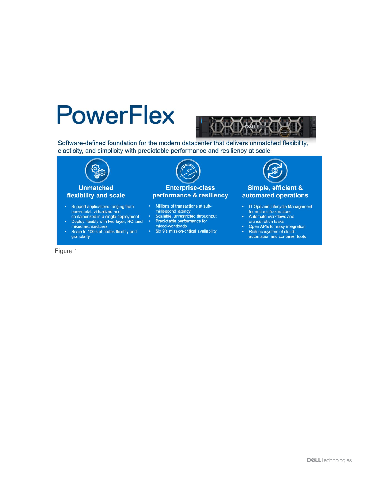
PowerFlex is a software-defined storage platform designed to significantly reduce operational and
infrastructure complexity empowering organizations to move faster by delivering flexibility, elasticity, and
simplicity with predictable performance and resiliency at scale. The PowerFlex family provides a foundation
that combines compute as well as high performance storage resources in a managed unified fabric. Flexibility
is offered as it comes in multiple hardware deployment options such as integrated rack, appliance or ready
nodes, all of which provide Server SAN, HCI and storage only architectures.
PowerFlex overview
PowerFlex provides the flexibility and scale demanded by a range of application deployments, whether they
are on bare metal, virtualized, or containerized.
It provides the performance and resiliency required by the most demanding enterprises, demonstrating six 9s
or greater of mission-critical availability with stable and predictable latency.
Easily providing millions of IOPs at sub-millisecond latency, PowerFlex is ideal for both high performance
applications and for private clouds that desire a flexible foundation with synergies into public and hybrid cloud.
It is also great for organizations consolidating heterogeneous assets into a single system with a flexible,
scalable architecture that provides the automation to manage both storage and compute infrastructure.
PowerFlex 3.5 new features
7 Dell EMC PowerFlex: Introduction to Replication | H18391
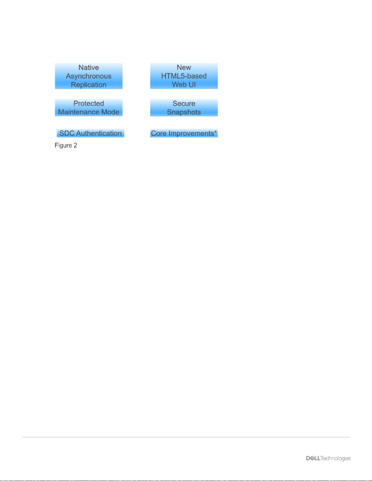
2 PowerFlex 3.5 new features
There is much more than replication in this release, so it is worth mentioning some additional features.
New features
2.1 Native asynchronous replication
This much anticipated feature is the key subject of this paper and will be covered in detail.
2.2 Protected Maintenance Mode
Protected Maintenance Mode, or PMM, offers better data protection over Instant Maintenance Mode. While
Instant Maintenance Mode, or IMM, offered the ability to perform node maintenance very quickly, there was
some exposure to potential data unavailability or loss should an additional device or node experience failure.
PMM creates a temporary third copy of the node’s data throughout the system spare capacity during the
maintenance period. When maintenance is complete, the deltas are synced back to the maintained node.
While it takes longer to perform than IMM, it preserves full data protection throughout the maintenance period
and vastly reduces concern for data loss and availability.
2.3 SDC authentication
Authentication of SDCs is better secured with CHAP, or Challenge-Handshake Authentication Protocol. It
allows the MDM to validate the authenticity of each SDC when it is first attached and to establish secrets
between the SDCs and SDSs to regulate access to volumes. The MDM regularly refreshes the secrets,
forcing the SDCs and SDSs to re-authenticate on a regular basis.
PowerFlex 3.5 new features
8 Dell EMC PowerFlex: Introduction to Replication | H18391
2.4 New WebUI
The PowerFlex 3.5 release offers a new, streamlined HTML5-based user interface which is consistent with
other Dell Technologies™ product solutions.
This primary dashboard view displays the majority of system activity at a single glance while also
preserving the ability to drill into all PowerFlex elements to view or manage them.
2.5 Secure snapshots
Secure snapshots were added to meet customer business and statutory requirements for data retention.
Secure snapshot with 1 year expiration time.

PowerFlex 3.5 new features
9 Dell EMC PowerFlex: Introduction to Replication | H18391
Once a snapshot is created with the secure option, it cannot be deleted until the assigned expiration time is
reached. For cases where secure snapshots are created by mistake, or must be removed for other reasons,
there is a formal process integrated with Dell support that must be followed to delete them. Note also that in
3.5, snapshots now can be created with read-only access, whether they are secure or not.
2.6 Core improvements
There are several core improvements in 3.5, but a few merit special mentions. Release 3.5 adds a Fine
Granularity Metadata cache which eliminates the two-step metadata lookup required for FG volume read I/Os.
Up to 32GB of FG pool metadata can be cached per SDS. The cache is not persistent and resides in DRAM.
It is updated either on new reads after an SDS reboots or upon a cache-miss. This dramatically improves FG
read performance for recent and frequently read IOs.
Data resiliency has been improved with two new features. Persistent checksum is now available for data
residing on Medium Granularity storage pools, and this is enabled by default on volumes created after the
upgrade to 3.5. Additionally, new Partial Disk Error handling prevents immediate media ejections and rebuild
of entire drives when only a few sectors fail. This provides a longer useful life of your storage media.
For more information on the PowerFlex 3.5 release, refer to the Getting to Know document in the product
documentation bundle found on the Dell EMC support site.
PowerFlex asynchronous replication architecture
10 Dell EMC PowerFlex: Introduction to Replication | H18391
3 PowerFlex asynchronous replication architecture
To understand how replication works, we must first consider the basic architecture of PowerFlex itself.
PowerFlex basic architecture diagram
Servers contributing media to a storage cluster run the Storage Data Server (SDS) software element which
allows PowerFlex to aggregate the media while sharing these resources as one or more unified pools on
which logical volumes are created.
Servers consuming storage run the Storage Data Client (SDC) which provides access to the logical volumes
via the host SCSI layer. Note that iSCSI is not used, but instead, a resilient load-managing, load-balancing
network service which runs on TCP/IP storage networks.
The Metadata Manager (MDM) controls the flow of data through the system but is not in the data path.
Instead, it creates and maintains information about volume distribution across the SDS cluster and distributes
the mapping to the SDC informing it where to place and retrieve data for each part of the address space.
These three base elements comprise the fundamental parts of best software-defined storage solution today,
one that scales linearly to hundreds of SDS nodes.
When considering architectural options for replication, maintaining the scalability and resiliency of PowerFlex
was critical. The replication architecture in PowerFlex is a natural extension of the fundamentals just
described.
PowerFlex asynchronous replication architecture
11 Dell EMC PowerFlex: Introduction to Replication | H18391
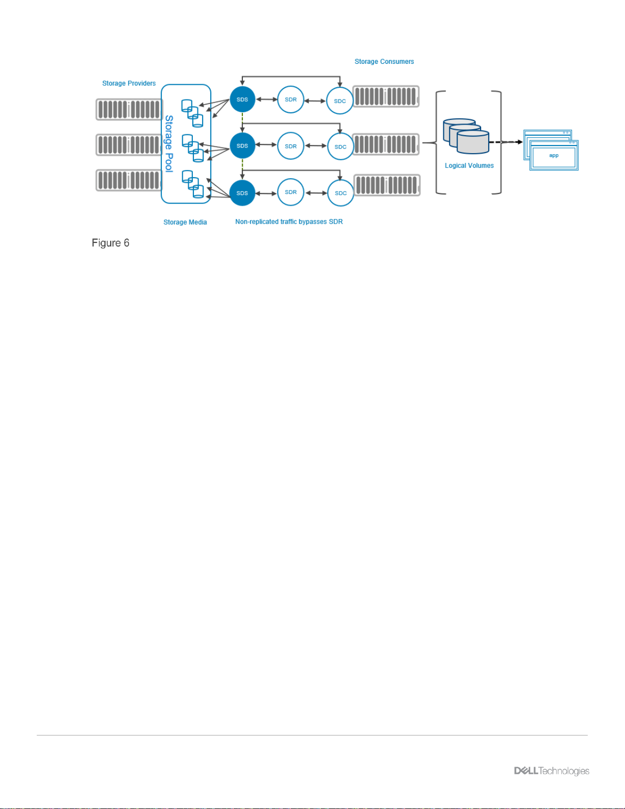
PowerFlex basic replication architecture
PowerFlex 3.5 introduces a new storage software component called the Storage Data Replicator. Figure 6
depicts where it fits into the overall PowerFlex architecture. Its role is to proxy the I/O of replicated volumes
between the SDC and the SDSs where data is ultimately stored. It splits write I/Os sending one copy on to the
SDSs and another to a replication journal volume. As it sits between the SDS and SDC, from the point-of-view
of the SDS, the SDR appears as, and behaves as, an SDC sending writes. Conversely, to the SDC, the SDR
appears as, and behaves as, an SDS to which writes can be sent.
The SDR only mediates the flow of traffic for replicated volumes, and as always, the MDM instructs each of
these elements where to read and write data. Writes related to non-replicated volumes passes directly from
the SDC to the SDSs, as always. This is facilitated by the volume mapping presented to the SDC by the
MDM, determining which volume’s data is sent directly to the SDSs, and which volume’s data is routed
through the SDR and then to the SDS.
3.1 Journaling and snapshotting
There are two schools of thought concerning how replication is implemented. Many storage solutions
leverage a snapshot approach. With snapshots, it is easy to identify the block change delta between two
points in time. However, as Recovery Point Objectives get smaller, the number of snapshots increase
dramatically, which places hard limits on how small RPOs can be. Instead, PowerFlex uses a journalingbased approach.
Journaling provides the possibility of very small RPOs, and, importantly, it is not constrained by the maximum
number of available snapshots in the system, or on a given volume.
Checkpoints are maintained in journals, and those journals live as volumes in a storage pool. The journal
volumes resize dynamically as writes ebb and flow, so the overall size of the journal buffer will vary over time.
3.2 Journaling space reservations
The reservation size of the journal volume is set by the user and is measured as a percentage of the storage
pool in which it is contained. For cluster installations that do not require replication, no journal space
reservations are made. This brings up our first system design consideration concerning replication. We need
space in one or more storage SSD or NVMe pools to provide a home for journal files. To determine how
much space, account for all the write I/O of your replicated volumes including the aggregated write size and
rate. Add a margin of safety of 15% for the volume overhead, journal write timestamps, and the journal-

PowerFlex asynchronous replication architecture
12 Dell EMC PowerFlex: Introduction to Replication | H18391
related handshaking. Consider also that you should always maintain enough free space reserves to sustain a
complete SDS node ejection. These additional node ejection reserves should be proportionate to the
percentage of storage space contributed by a single node, or multiple nodes for cases where Protected
Maintenance Mode may be used simultaneously on multiple nodes. Consider snapshots as well. If writes
have been issued to writable snapshots, that should be accounted for in your free space reservations.
When sizing the journal volume reservation, also consider the possibility of a communications failure to the
remote site. If the journals are unable to transmit, the journals will fill the buffer, potentially filling it altogether.
So, you must consider the maximum cumulative writes that might occur in that time. If the journal buffer space
fills completely, the replica-pair volumes will require re-initialization.
For an example, we determine that an application generates 890MB/s of writes. Adding 15% overhead (plus
an allowance for node ejection), we have 890MB/s x 1.15, which is 1.0235GB/s. Next, we have decided we
wish to balance availability with storage conservation and allow a maximum of two hours of network failure
between the two storage clusters. This translates to 1.0235GB/s * 7200 seconds which is 7.3693TB of data.
Since the journaling reservation is expressed as a percentage, we divide our 7.3692TB of buffer space by the
size of our storage pool which is 204TB. The space reservation for this app is then 3.6%. Repeat this for each
application being replicated. If this is the only application being replicated, round the figure to 4%.
3.3 Journal management
Each cluster can be both a replication source and a target. This allows customers to split applications
between clusters while protecting application availability for both.
PowerFlex simplified replication I/O flow
The volume mapping on the source SDC sends writes for replicated data to the SDR, which duplicates the
write and forwards it. The local SDSs process those writes normally, while the SDR assembles the journal
files which contain checkpoints to preserve write order.

PowerFlex asynchronous replication architecture
13 Dell EMC PowerFlex: Introduction to Replication | H18391
Journals are batched in the journal buffer on the source system. As they near the head of the queue they are
scanned, and duplicate block writes are consolidated (folded) to minimize the volume of data being sent over
the wire.
The journals are sent to the remote target journal buffer by the SDR over dedicated subnets on local or
external networks assigned to replication and, once acknowledged, are removed.
On the target system, the journals are processed by the SDR, passing the writes on to the relevant SDSs.
Remember, the SDS thinks the I/O is coming from an SDC, so the SDS manages the primary and secondary
copy writes as usual. This addresses a commonly asked question: How is compression affected? Because
the SDR is a mediator between the SDC and the SDS, it plays no role in compression. Compression occurs in
the same way it did with the release of PowerFlex 3.0, with the SDS handling all aspects of compression. This
means that data sent over the wire is not compressed.
Once the target SDR receives acknowledgment from the target SDS, it proceeds to the next write contained
in the journal interval being processed. When the last write in a journal interval is processed and
acknowledged, the interval space in the journal is made available for reuse.
There are a variety of other SDR processes working together to protect the integrity of your data, but this
description covers all the fundamentals.
There is one limitation worthy of mention related to volume migration. It is not possible to migrate replicated
volumes from one Protection Domain to another. This is due to the fact that the replication journals to not
span Protection Domains.

Deploying and configuring PowerFlex clusters for replication
14 Dell EMC PowerFlex: Introduction to Replication | H18391
4 Deploying and configuring PowerFlex clusters for replication
Proper system and storage sizing must be performed before deploying any new PowerFlex clusters.
Replication adds additional sizing concerns. Your Dell Technologies technical sales resources have access to
a system sizing utility which not only requires that your workload information is collected, profiled, and
characterized, but also your replication footprint, and network design and infrastructure are accounted for.
There are additional cluster setup requirements to consider when adding asynchronous replication. We need
• A way for the clusters participating in replication to communicate securely.
• To group volume pairs together into consistency groups.
• Methods of testing failure, or even distributing workload without impacting the primary application.
• Configuring the physical WAN network for replicating externally when the target cluster is in another
data center
• Additional IP addresses for replication activity
We will cover all these topics in this chapter.
4.1 Deployment and configuration
When deploying cluster pairs to be used with replication, there are a few required configuration steps.
4.1.1 The exchange of storage cluster Certificate Authority root certificates
CA root certificates must be exchanged between replicating clusters to protect from possible security attacks.
Since this is a security-sensitive issue, this step is performed using the PowerFlex command line interface.
On each system, a certificate is created and sent to the other host in the replicated pair. The command:
scli –extract_root_ca –certificate_file /tmp/sys0.cert
extracts the certificate from the cluster. The certificate is then manually copied to the partner cluster.
To import the certificate, on the partner system, we use a command of the following form:
scli –add_trusted_ca –certificate_file /tmp/sys0.cert –comment Acme_HQ
Once the certificates are generated, exchanged, and imported on both systems, the certificate step is
complete.
4.1.2 Peering storage clusters
The next step required before configuring replicated volume pairs is Peering. Peering establishes the data
paths between the systems. This can be done using the new PowerFlex HTML5-based WebUI, but there is
one piece of critical information we will need first. We will use the PowerFlex CLI to capture the MDM System
IDs for both storage clusters by logging into the PowerFlex CLI. The act of authenticating to the cluster will
reveal the required cluster IDs. You will need the IDs from both the source and the target systems.
Capturing a PowerFlex system ID

Deploying and configuring PowerFlex clusters for replication
15 Dell EMC PowerFlex: Introduction to Replication | H18391
To begin peering, navigate to the REPLICATION tab in the PowerFlex WebUI and expand it by clicking on it.
From there, select the Peer Systems tab.

Deploying and configuring PowerFlex clusters for replication
16 Dell EMC PowerFlex: Introduction to Replication | H18391
• To add the system peer, click the ADD button.
Add peer
• And lastly, complete the form by clicking Add Peer.
Add peer system
• Once you add the peer, repeat the process on the target storage cluster using the same steps,
entering the remote system ID of the primary cluster. Once that is complete, the systems are peered
in both directions, and you are ready to start pairing your replicated volumes.
4.2 Replication Consistency Groups
Replication Consistency Groups, or RCGs, establish the attributes and behavior of the replication of one or
more volume pairs. One such attribute is the target replication storage cluster. While a given RCG can
replicate to only one target cluster, in principle other RCGs may replicate to other clusters provided they have
exchanged certificates and have been peered. In the initial release of PowerFlex native asynchronous
replication, however, a source site may only be peered with one other site. Future releases will permit
additional replication topologies.
Before creating RCGs, our replication volumes must exist on both the source and target systems, and they
must be of the same size. But are not required to reside in a storage pool of the same type (MG vs. FG.), nor
must they have the same properties (thick vs. thin, compressed vs. non-compressed). If there comes a time
when a volume needs to be resized, the target volume should be expanded first. Expanding the volumes in
this manner prevents any disruptions in replication. This means it is mandatory to know what volumes are
being replicated, so that this practice is followed when data outgrows the volume.

Deploying and configuring PowerFlex clusters for replication
17 Dell EMC PowerFlex: Introduction to Replication | H18391
RCGs are very flexible. For some use cases, you might assign all volumes associated with an application to a
single RCG. For larger applications, you might create multiple RCGs based on data retention, data type, or
related application quiescing procedures to enable read-consistent snapshots when needed. In general,
RCGs are crash-consistent. Snapshots can be made read-consistent if application quiescing rules were
followed when they were created. This places no special requirements on the storage platform, but generally
requires scripting with the application.
Concerning Recovery Point Objectives specified in the RCG configuration, you will see in Figure 13 below,
that they can be set between 30 seconds and 60 minutes. PowerFlex release 3.5, offers the smallest RPO of
30 seconds. Over time, this lower limit will be reduced as lower RPOs are validated for production use.
To create an RCG, log into the new WebUI and navigate to REPLICATION->RCGs->ADD.
This first step in creating an RCG involves providing:
• A name for the RCG
• The desired RPO
• The source Protection Domain
• The target system
• The target Protection Domain
Add RCG > set RPO

Deploying and configuring PowerFlex clusters for replication
18 Dell EMC PowerFlex: Introduction to Replication | H18391
To complete the operation, we will first match up the source and target volumes.
Add RCG > match source and target volumes
• Unpaired volumes appear in the source and target lists in dark text. When a source volume is
selected, un-paired target volumes are highlighted provided they have the same capacity as the
selected volume. Once the two volumes have been selected, the ADD PAIR button is selected,
moving the volume pair into the list appearing on the right. Once all volumes have been added,
proceed by clicking the NEXT button.
• A summary is then displayed where you can select pairs and remove them if needed.
Add RCG > review pairs

Deploying and configuring PowerFlex clusters for replication
19 Dell EMC PowerFlex: Introduction to Replication | H18391
• The final mouse click gives us the option of creating the RCG and initiating the volume
synchronization immediately or deferring the synchronization when there might be concern of
workload interference in production environments during periods of peak load.
• You do have the ability to add or remove volumes from an RCG at any time. Out of concern for
excessive I/O and based on the size of the volumes you may elect to add only single volume pairs at
a time to the RCG when it is first created, but this is usually not necessary.

Replication monitoring and configuration
20 Dell EMC PowerFlex: Introduction to Replication | H18391
5 Replication monitoring and configuration
5.1 The replication dashboard
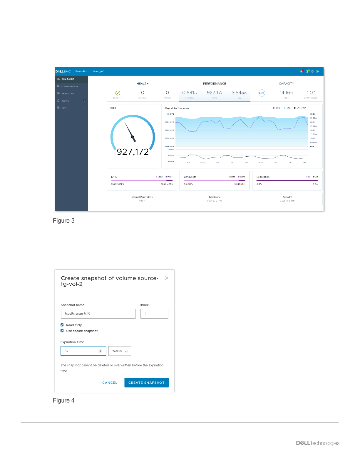
The REPLICATION > Overview tab gives us a dashboard to determine the overall health of replication.
Replication overview
5.2 The Replication Consistency Group tab
• The REPLICATION > RCGs tab in the WebUI allows us to monitor the health and status of the
individual Replication Consistency groups or add new ones.
RCG overview
You can select any RCG by clicking on its checkbox, and once you do, there are management commands
available to you.

Replication monitoring and configuration
21 Dell EMC PowerFlex: Introduction to Replication | H18391
RCG management options
Pause: Pauses replication of writes. This prevents journals from being shipped to the target cluster until
replication is resumed again.
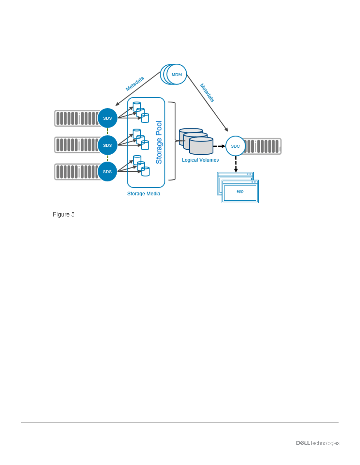
Create Snapshots: Generates snapshots of each volume in the RCG on the target system. This can be
useful for remotely testing an application or DR activity. There is no facility to delete the snapshots, so they
will have to be unmapped and deleted manually on the target system.
Failover: Forces a failover event, passing primary ownership of the volumes within the RCG to the target
system. Once this is done, for planned failovers, you can also select the Reverse command to keep the
original source volumes in sync.
Test Failover: This automatically creates a snapshot on the target system and replaces the original target
volume mapping with a mapping to the snapshot. Using this command, you can perform write testing to the
volume while preventing the source volume from being corrupted by the test activity.

Replication monitoring and configuration
22 Dell EMC PowerFlex: Introduction to Replication | H18391
5.3 Volume access
There are some replication-related commands that can be performed in both the WebUI and the CLI, and in
fact, most of them can be performed in the WebUI. These include
• Creating Volumes
• Mapping volumes for read-write access
• Creating Replication Consistency Groups
Other commands must be performed using the CLI or REST API, including
• Performing the Certificate Authority certificate exchange
• Mapping volumes for read-only
• Setting the target volume access mode for the RCG
Due to security concerns, the default behavior of a newly created Replication Consistency Group prevents the
target system from reading the target volume. The access modes are defined as:
• no_access (default behavior)
• read_only
For RCGs created with the WebUI, one can grant target read_only volume access with the following
command after logging into the PowerFlex CLI on the source system:
Once this command is issued, we can access all volumes included in the RCG on the target storage cluster.
5.3.1 Access mode for mapping the target volume
We are already familiar with mapping volumes and by default, volumes are mapped with read_write access.
This creates a conflict with the mapping of target volumes. Since we have set the remote access mode of the
Replication Consistency Group point-of-view to read_only, this is incompatible with the default mapping
access mode of read_write volume mapping offered by the WebUI. Therefore, we must log onto the target
system and manually map all volumes in the RCG to the target system using this command:
Once this is done, you will be able to proceed with failover-related replication commands.

Replication monitoring and configuration
23 Dell EMC PowerFlex: Introduction to Replication | H18391
5.3.2 Test failover behavior
In Section 3.2, we discussed the Test Failover command which is found in the RCG command menu. Once
the remote volume access and secondary cluster volume mapping tasks are completed, we can test the RCG
failover, and attach our volumes to our application or filesystem. The act of issuing the Test Failover
command will:
• Create a snapshot on the target system for all volumes attached to the RCG
• Replace the pointer used by the volume mapping for each volume with a pointer to its snapshot
• Change the access mode of the volume mapping of each volume on the target system to read_write
These steps all happen in milliseconds, making the volumes immediately write-accessible to the Storage
Data Client. This means that you can do whatever you wish with the volumes, whether it is using them for
opening a database, an application, or mounting a filesystem. Since they are snapshots, you can freely test
your application, and if the storage pool is of the same type as the source system, your application will
perform equally well. In some cases, you might use compression with fine granularity volumes on the primary,
while your target volume might reside on medium granularity volumes. In this case, the application may
perform better than in the production environment. This feature provides a few additional benefits:
• Enables you to perform resource-intensive operations on secondary storage without impacting
production
• Test application upgrades on the target system without production impact
• Ability to attach different, and higher-performing compute systems or media in the target environment
• Ability to attach systems with different hardware attributes such as GPUs in the target domain
• Ability to run analytics on the data without impeding your operational systems
• Perform what-if actions on the data because that data will not be written back to prod
• Eliminates many manual storage tasks because the test is fully automated along with the snapshots
In summary, replication testing can be leveraged to reduce impact and risk.
5.3.3 Failover behavior
When the RCG Failover command is issued, the access mode of the original source volumes switches to
read_only. This means that in the case of planned fail-over, you are required to shut your applications down.
The access mode of the target volumes switches to read_write. There is nothing else to do, and the behavior
is the same if the failover is issued from the command line interface or REST API. If the failover is of a
planned nature such compute node maintenance, but the original storage cluster continues functioning, you
have the option of initiating the RCG command to reverse replication. This keeps the volume pairs in sync. If
you will be shutting down the primary system for a prolonged period, you will likely have to re-initialize your
volume pairs.
One thing to bear in mind is that each PowerFlex storage system creates unique volume and SCSI IDs, so
they will be different for the source and target systems.

Replication monitoring and configuration
24 Dell EMC PowerFlex: Introduction to Replication | H18391
5.3.4 Create snapshots behavior
This RCG command creates snapshots for all volumes attached to the RCG on the target side, but it does not
manage the snapshots any further. Consuming the snapshots is done separately. From there, to test your
applications, you would need to:
1. Map the volumes to a target SDC compute system(s)
2. Use the volumes as needed
3. Un-map the volumes when they are no longer needed
4. Delete the snapshots
5.3.5 Monitoring journal capacity and health
By logging onto the WebUI and navigating to REPLICATION > Journal Capacity you can track the utilization
of your Journal space reservation(s).
Here, we see that we have reserved 10% or 636GB of Storage Pool sp1 for journaling, and we currently have
4.8GB of journal content in use. If there is concern that the space reservation is too small or large, you can
change it at any time.

Replication monitoring and configuration
25 Dell EMC PowerFlex: Introduction to Replication | H18391
Just click on the storage pool checkbox and click on the Modify command. You can now change the
reservation if you wish.

PowerFlex 3.5 networking considerations
26 Dell EMC PowerFlex: Introduction to Replication | H18391
6 PowerFlex 3.5 networking considerations
All networking topologies, availability, and load balancing options previously recommended remain fully
supported. However, PowerFlex replication adds a possible wrinkle in the network fabric that we need to
account for. There is some network overhead (~15%) associated with replication and related journaling
activity.
6.1 TCP/IP port considerations
PowerFlex port and traffic overview
This diagram above provides us with a representation of all the logical software components of PowerFlex as
well as the TCP/IP ports used by those components. We see the ports which must be associated with firewall
rules on our PowerFlex server hosts. We can also see, the ports related specifically to remote replication
which include:
1. Port 11088 which links the SDC and MDM to the SDR and also links the SDR to the remote SDR.
2. Port 7611 which allows MDM communications between two replicating clusters.
6.2 Network bandwidth considerations
First, there are general considerations for communications between replicating clusters. The volume of
writes cannot exceed the networking bandwidth of the intra-cluster networks. Also factor in 15% for
the overhead of replication processing. Plan that at least one path in the intra-cluster network will fail and
make certain the expected write bandwidth can be sustained with latencies falling within the requirements of

PowerFlex 3.5 networking considerations
27 Dell EMC PowerFlex: Introduction to Replication | H18391
your applications and service levels. Customers with newly deployed 25GbE networks, like those deploying
the PowerFlex rack or appliance with four data networks are likely not effected.
6.3 Native PowerFlex 3.5 IP load balancing
Release 3.5 offers a transformative change. SDC network path failover time prior to this new release was
greater than 15 seconds, causing issues for some highly I/O-sensitive applications. In 3.5, the path failover for
native load balancing has now fallen to three seconds. Those customers who previously chose to deploy
LACP for that reason can now revert to native networking if they choose to do so.
6.4 Remote replication networking
For networking configurations where access to the remote cluster passes through a static routed WAN, or
where the networking baseline latency is greater than 50ms, the greatest concern is latency. For any
configuration, there is a latency limit of 200ms, which is a potential issue for remote clusters. For network
paths exceeding 200ms, it is likely a path approaching from the other side of the Earth will perform better.
This configuration will require at least two subnets connected to the target system, and with the higher
latency, bandwidth can become an issue, so thoroughly test the latency and throughput limits of your links
and keep the replication bandwidth under your known thresholds!
For planning purposes, in addition to the 15% replication overhead, leave a 20% margin of safety for
replication traffic over a WAN.
Cross-site traffic must be considered to greater extent here since the traffic passes over the WAN to the
cluster at the remote site.
Refer to the product Networking Best Practices guide for more information.
In certain cases, when latency is high, you will likely need to increase the RPO of your Replication
Consistency Groups. This can be done in the RCGs tab. Visit REPLICATION > RCGs, select an RCG, and
click the Modify > Modify RPO command to increase the RPO value.

PowerFlex 3.5 networking considerations
28 Dell EMC PowerFlex: Introduction to Replication | H18391
6.4.1 Routing and firewall considerations for remote replication
Section 6.1 emphasized TCP/IP ports for MDM (7611) communications between replicating clusters as well
as SDR (11088) communications used in transporting replication journal logs.
For replication use cases involving distant clusters, we will need interconnectivity for these IP ports provided
over routed networks. The best practice for networking in this situation is to reserve two networks for intracluster SDR and MDM communications. Here is an example of such a configuration.

PowerFlex 3.5 networking considerations
29 Dell EMC PowerFlex: Introduction to Replication | H18391
This configuration contains interconnected WAN switches at both ends. As an example, for Cisco switches
the following command sequences would be in order.
The routes from the primary WAN switch to the gateway:
hostname(config)# route flex-mdm-sdr1 30.30.214.0 255.255.255.0 192.168.1.1
hostname(config)# route flex-mdm-sdr3 32.32.214.0 255.255.255.0 192.168.1.2
The routes from the secondary WAN to the gateway:
hostname(config)# route flex-mdm-sdr2 31.31.214.0 255.255.255.0 192.168.1.1
hostname(config)# route flex-mdm-sdr4 33.33.214.0 255.255.255.0 192.168.1.2

System component, network, and process failure
30 Dell EMC PowerFlex: Introduction to Replication | H18391
7 System component, network, and process failure
For our final considerations related to replication, we must face the reality that servers, processes, and
network links do periodically fail. The following tests account for a few of these types of failures. The tests
were performed on a 6-node R740xd PowerFlex node cluster with three SSDs per storage pool. Replication
was active on both storage pools at the time of the failures.
7.1 SDR failure scenarios
Let us start with a baseline workload. We will go on to fail an SDR, observe the impact, and observe the later
impact of restarting it.
Immediately after failing the SDR,
we see a drop in I/O processing
The I/O resumes slightly lower
After restarting, the I/O is slightly
impacted, but eventually ramps
back up to the baseline.

System component, network, and process failure
31 Dell EMC PowerFlex: Introduction to Replication | H18391
7.2 SDS failure scenarios
We will perform the same test for SDS failure.
Baseline workload
IOPs just after fail the SDS
Five seconds later, it starts
ramping up and within 10
seconds resumes the baseline
workload indicating the system
was more than capable of
handling the workload with five
active SDS systems
And as expected, we see rebalance activity
Next, we restart the failed SDS, and
we see an immediate drop, but not
substantial after restarting the SDS
As the rebalance continues, the I/O
ramps back up to the baseline

System component, network, and process failure
32 Dell EMC PowerFlex: Introduction to Replication | H18391
7.3 Network link failure scenarios
Now, we will fail a network link to demonstrate how the updated native load balancing affects our I/O rate. The
system has a network configuration consisting of four data links between systems.
Again, we establish a baseline
We fail a link and notice a 3second drop in I/O
5 seconds later, the baseline
returns
After reconnecting the failed port, the baseline I/O level resumes within a few seconds with no noticeable dip.
All these failure scenarios demonstrate the resilience of PowerFlex. It also shows that the system is well
tuned, and that rebuild activity does not severely impact our workload.

Conclusion
33 Dell EMC PowerFlex: Introduction to Replication | H18391
8 Conclusion
You should now have a better understanding of PowerFlex 3.5 native asynchronous replication including
configuration and the journaling method selected.
In summary, it is recommended you start small. Follow the recommendations mentioned. Account for the total
replication bandwidth, including all write I/O of all your replicated data. Size your journaling space reserves as
recommended. Include margins of error for network and component failure. Include 15% overhead for the
replication process itself as well, as possible failures of PowerFlex processes including SDS system or other
component failures.

Technical support and resources
34 Dell EMC PowerFlex: Introduction to Replication | H18391
A Technical support and resources
Dell.com/support is focused on meeting customer needs with proven services and support.
Storage technical documents and videos provide expertise that helps to ensure customer success on Dell
EMC storage platforms.
 Loading...